Embed Size (px)
Citation preview
Software Architecture in Industrial Applications
Dilip Soni, Robert L. Nerd, and Christine Hofmeister
{ dsoni, rnord, chofmeister} @scr.siemens.com
Siemens Corporate Research Inc.
755 College Road East, Princeton, NJ 08540
Abstract
To help us identify and focus on pragmatic and concrete
issues related to the role of software architecture in large
systems, we conducted a survey of a variety of software
systems used in industrial applications. Our premise, which
guided the examination of these systems, was that software
architecture is concerned with capturing the structures of a
system and the relationships among the elements both
within and between structures. The structures we found fell
into several broad categories: conceptual architecture,
module interconnection architecture, code architecture, and
execution architecture. These categories address different
engineering concerns. The separation of such concerns,
combined with specialized implementation techniques,
decreased the complexity of implementation, and improved
reuse and reconfiguration.
1. Introduction
Software architectures describe how a system is decom-
posed into components, how these components are inter-
connected, and how they communicate and interact with
each other. When poorly understood, these aspects of
design are major sources of errors.
The research area of software architecture is an emerg-
ing one with little agreement over the definition of architec-
ture. The only consensus seems to be that architecture is
related to the structure of a system and the interactions
among its components [14, 25]. Some of the work focuses
on building theory and models of architecture [2, 31], with
an emphasis on taxonomy, description languages, and veri-
fication of architectural properties. Several efforts have
been made to generate code based on parts of architecture
[13, 27]. In general, the literature relies heavily on informal
examples and anecdotes, and most of this work has notbeen proven to be scalable for large systems. Also missing
from prior work is the focus on the pragmatic role of archi-
tecture in software development activities [1O, 33].
Permission to copy without fee all or part of this material isgranted provided that the copies are not made or distributed fordirect commercial advantage, the ACM copyright notice and thetitle of the publication and its date appear, and notice is giventhat copying is by permission of the Association of ComputingMachinery. To copy otherwise, or to republish, requires a feeand/or specific permission.ICSE ’95, Seattle, Washington USA@ 1995 ACM 0-89791 -708- 1/95/0004 ...$3.50
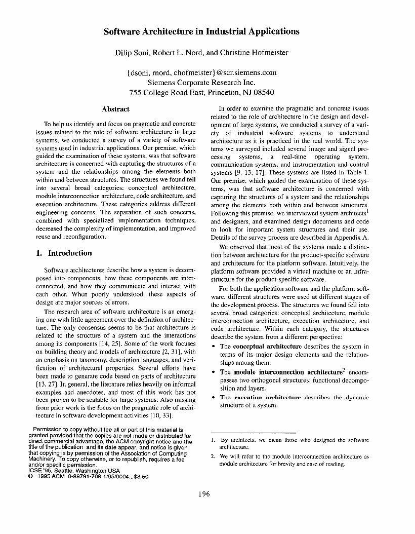
In order to examine the pragmatic and concrete issues
related to the role of architecture in the design and devel-
opment of large systems, we conducted a survey of a vari-
ety of industrial software systems to understand
architecture as it is practiced in the real world. The sys-
tems we surveyed included several image and signal pro-
cessing systems, a real-time operating system,
communication systems, and instrumentation and control
systems [9, 13, 17]. These systems are listed in Table 1.
Our premise, which guided the examination of these sys-
tems, was that software architecture is concerned with
capturing the structures of a system and the relationships
among the elements both within and between structures.
Following this premise, we interviewed system architects’
and designers, and examined design documents and code
to look for important system structures and their use.
Details of the survey process are described in Appendix A.
We observed that most of the systems made a distinc-
tion between architecture for the product-specific software
and architecture for the platform software. Intuitively, the
platform software provided a virtual machine or an infra-
structure for the product-specific software.
For both the application software and the platform soft-
ware, different structures were used at different stages of
the development process. The structures we found fell into
several broad categories: conceptual architecture, module
interconnection architecture, execution architecture, and
code architecture. Within each category, the structures
describe the system from a different perspective:
●
●
●
The conceptual architecture describes the system in
terms of its major design elements and the relation-
ships among them.
The module interconnection architecture encom-
passes two orthogonal structures: functional decompo-
sition and layers.
The execution architecture describes the dynamic
structure of a system.
1
2,
By architects, we mean those who designed the software
architecture,
We will refer to the module interconnection architecture as
module architecture for brevity and ease of reading.
196
System Application Domain Size Important System Characteristics
A user interface small window management
B* signal processing medium monitoring, real-time
c image and signal processing medium high throughput
D* signal processing medium monitoring, real-time, safety-critical
E* image and signal processing very large high throughput
F* computing environment medium management of distributed information
(_&# instrumentation and control large fault tolerance, multi-processing, safety-critical
H instrumentation and control large multi-processing
I operating system large real-time
J communication very large multi-processing
K* communication very large distributed, heterogenous, multi-processing
small: fewer than 100 KLOC; medium: 100-500 KLOC; large: 500-1 MLOC; very large: more than 1 MLOC
* These systems were selected for detailed study.----- “.,. .-‘lable 1: Summary ot the surveyed Systems
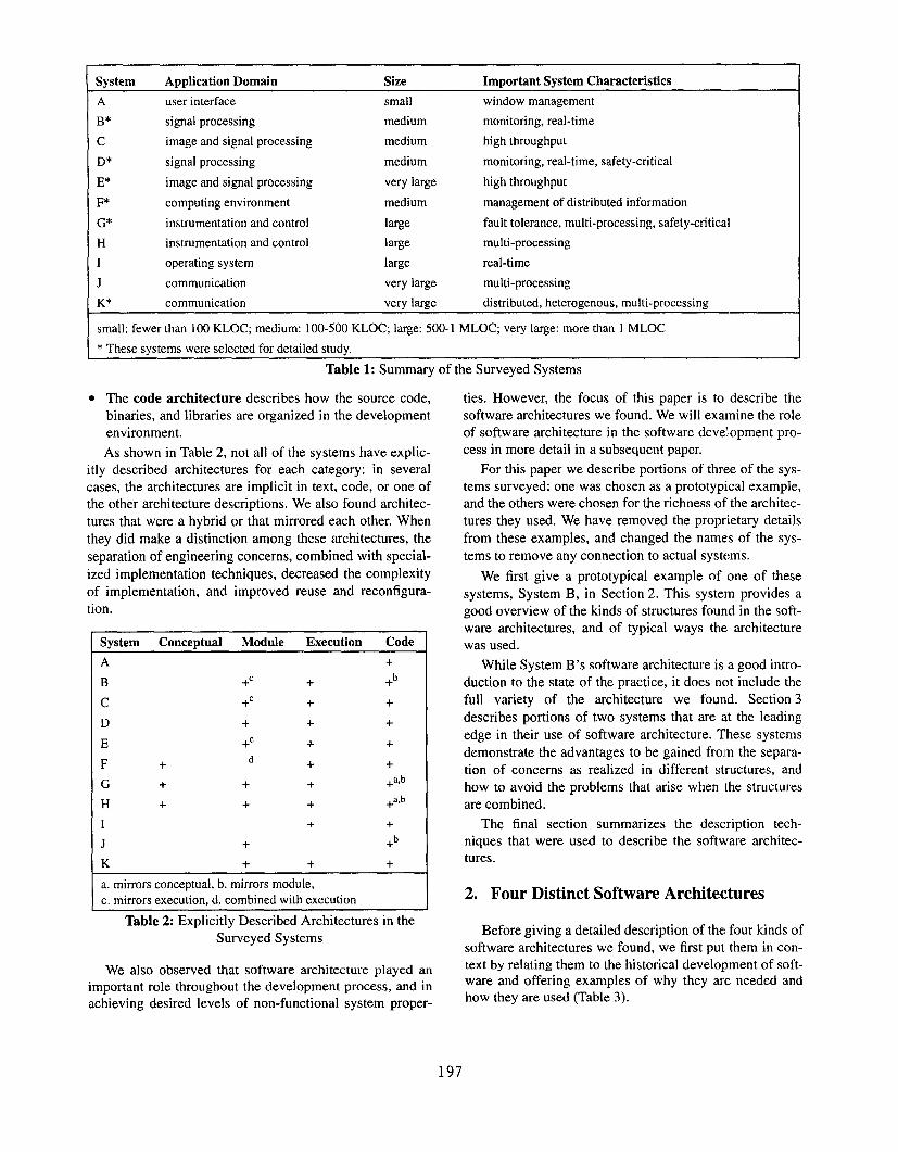
● The code architecture describes how the source code, ties. However, the focus of this paper is to describe the
binaries, and libraries are organized in the development
environment.
As shown in Table 2, not all of the systems have explic-
itl y described architectures for each category: in several
cases, the architectures are implicit in text, code, or one of
the other architecture descriptions. We also found architec-
tures that were a hybrid or that mirrored each other. When
they did make a distinction among these architectures, the
separation of engineering concerns, combined with special-
ized implementation techniques, decreased the complexity
of implementation, and improved reuse and reconfigura-
tion,
System Conceptual Module Execution Code
A +
B +C + +b
c +’ + +
D + + +
E +C + +
F + d + +
G + + + +a,b
H + + + +o,b
1 + +
J + +b
K + + +
a. mirrors conceptual, b. mirrors module,
c. mirrors execution, d. combined with execution
Table 2: Explicitly Described Architectures in the
Surveyed Systems
We also observed that software architecture played an
important role throughout the development process, and in
achieving desired levels of non-functional system proper-
software architectures we found. We will examine the role
of software architecture in the software development pro-
cess in more detail in a subsequent paper.
For this paper we describe portions of three of the sys-
tems surveyed: one was chosen as a prototypical example,
and the others were chosen for the richness of the architec-
tures they used. We have removed the proprietary details
from these examples, and changed the names of the sys-
tems to remove any connection to actual systems.
We first give a prototypical example of one of these
systems, System B, in Section 2. This system provides a
good overview of the kinds of structures found in the soft-
ware architectures, and of typical ways the architecture
was used.
While System B‘s software architecture is a good intro-
duction to the state of the practice, it does not include the
full variety of the architecture we found. Section 3
describes portions of two systems that are ut the leading
edge in their use of software architecture. These systems
demonstrate the advantages to be gained frolm the separa-
tion of concerns as realized in different structures, and
how to avoid the problems that arise when the structures
are combined.
The final section summarizes the description tech-
niques that were used to describe the software architec-
tures.
2. Four Distinct Software Architectures
Before giving a detailed description of the four kinds of
software architectures we found, we first put them in con-
text by relating them to the historical development of soft-ware and offering examples of why they are needed and
how they are used (Table 3).
197
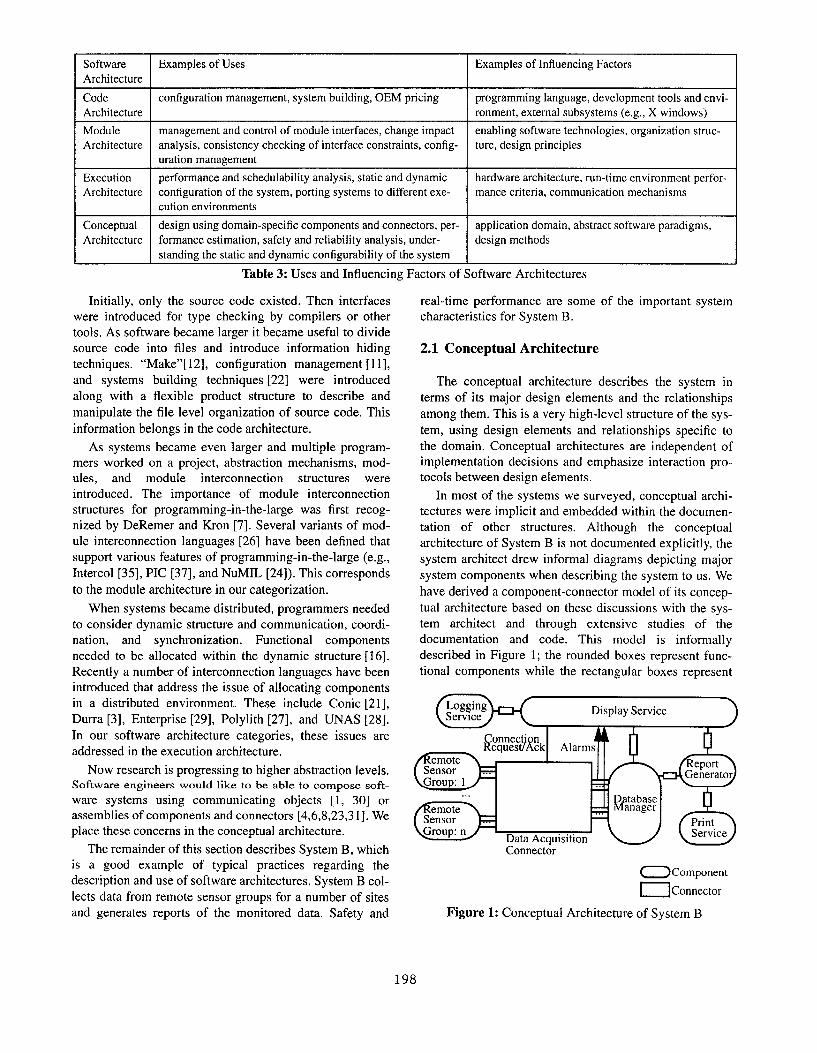
Software IExamples of Uses IExamples of Influencing Factors
Architecture
Code configuration management, system building, OEM pricing programming language, development tools and envi-
Architecture ronment, external subsystems (e.g., X windows)
Module management and control of module interfaces, change impact enabling software technologies, organization struc-
Architecture analysis, consistency checking of interface constraints, config- ure, design principles
uration management
Execution performance and schedtdability analysis, static and dynamic hardware architecture, run-time environment perfor-
Architecture configuration of the system, porting systems to different exe- mance criteria, communication mechanisms
cution environments
Conceptual design using domain-specific components and connectors, per- application domain, abstract software paradigms,
Architecture formance estimation, safety and reliability analysis, under- design methods
standing the static and dynamic configurability of the system
Table 3: Uses and Influencing Factors of Software Architectures
Initially, only the source code existed. Then interfaces
were introduced for type checking by compilers or other
tools, As software became larger it became useful to divide
source code into files and introduce information hiding
techniques. “Make”[ 12], configuration management[11 ],
and systems building techniques [22] were introduced
along with a flexible product structure to describe and
manipulate the file level organization of source code. This
information belongs in the code architecture.
As systems became even larger and multiple program-
mers worked on a project, abstraction mechanisms, mod-
ules, and module interconnection structures were
introduced. The importance of module interconnection
structures for programming-in-the-large was first recog-
nized by DeRemer and Kron [7]. Several variants of mod-
ule interconnection languages [26] have been defined that
support various features of programming-in-the-large (e.g.,
Intercol [35], PIC [37], and NuMIL [24]). This corresponds
to the module architecture in our categorization.
When systems became distributed, programmers needed
to consider dynamic structure and communication, coordi-
nation, and synchronization. Functional components
needed to be allocated within the dynamic structure [16].
Recently a number of interconnection languages have been
introduced that address the issue of allocating components
in a distributed environment. These include Conic [21],
Durra [3], Enterprise [29], Polylith [27], and UNAS [28].
In our software architecture categories, these issues are
addressed in the execution architecture.
Now research is progressing to higher abstraction levels.Software engineers would like to be able to compose soft-
ware systems using communicating objects [1, 30] or
assemblies of components and connectors [4,6,8,23,31]. We
place these concerns in the conceptual architecture.
The remainder of this section describes System B, which
is a good example of typical practices regarding the
description and use of software architectures. System B col-
lects data from remote sensor groups for a number of sites
and generates reports of the monitored data. Safety and
real-time performance are some of the important system
characteristics for System B.
2.1 Conceptual Architecture
The conceptual architecture describes the system in
terms of its major design elements and the relationships
among them. This is a very high-level structure of the sys-
tem, using design elements and relationships specific to
the domain. Conceptual architectures are independent of
implementation decisions and emphasize interaction pro-
tocols between design elements.
In most of the systems we surveyed, conceptual archi-
tectures were implicit and embedded within the documen-
tation of other structures. Although the conceptual
architecture of System B is not documented explicitly, the
system architect drew informal diagrams depicting major
system components when describing the system to us. We
have derived a component-connector model of its concep-
tual architecture based on these discussions with the sys-
tem architect and through extensive studies of the
documentation and code. This model is informally
described in Figure 1; the rounded boxes represent func-
tional components while the rectangular boxes represent
.
Data AcquisitionConnector
OCompone.t
mConnector
Figure 1: Conceptual Architecture of System B
198
ConnectionRequestlAck
1 I
... ...
...
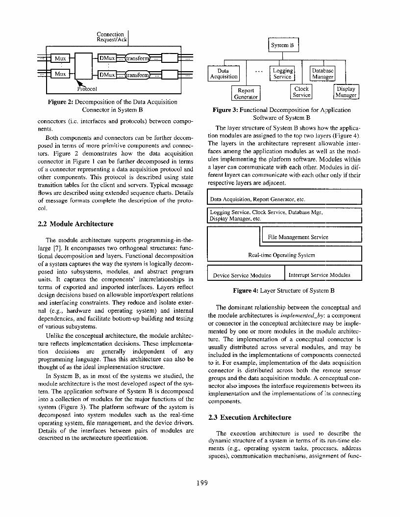
Figure 2: Decomposition of the Data Acquisition
Connector in System B
connectors (i.e. interfaces and protocols) between compo-
nents.
Both components and connectors can be further decom-
posed in terms of more primitive components and connec-
tors. Figure 2 demonstrates how the data acquisition
connector in Figure 1 can be further decomposed in terms
of a connector representing a data acquisition protocol and
other components. This protocol is described using state
transition tables for the client and servers. Typical message
flows are described using extended sequence charts. Details
of message formats complete the description of the proto-
col .
2.2 Module Architecture
The module architecture supports programming-in-the-
large [7]. It encompasses two orthogonal structures: func-
tional decomposition and layers. Functional decomposition
of a system captures the way the system is logically decom-
posed into subsystems, modules, and abstract program
units. It captures the components’ interrelationships in
terms of exported and imported interfaces. Layers reflect
design decisions based on allowable import/export relations
and interfacing constraints. They reduce and isolate exter-
nal (e.g., hardware and operating system) and internal
dependencies, and facilitate bottom-up building and testing
of various subsystems.
Unlike the conceptual architecture, the module architec-
ture reflects implementation decisions. These implementa-
tion decisions are general] y independent of any
programming language. Thus this architecture can also be
thought of as the ideal implementation structure.
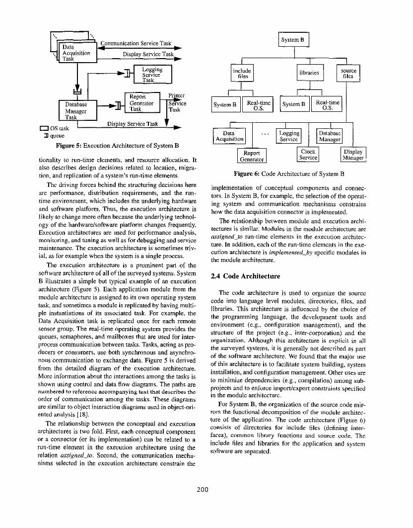
In System B, as in most of the systems we studied, the
module architecture is the most developed aspect of the sys-
tem. The application software of System B is decomposed
into a collection of modules for the major functions of the
system (Figure 3). The platform software of the system is
decomposed into system modules such as the real-time
operating system, file management, and the device drivers.
Details of the interfaces between pairs of modules aredescribed in the architecture specification.
System BI
1
Data . . . Logging
1’ F&
1
DatabaseAcquisition Service Manager
Report Clock Display
Generator Service Manager
Figure 3: Functional Decomposition for Application
Software of System B
The layer structure of System B shows how the applica-
tion modules are assigned to the top two layers (Figure 4).
The layers in the architecture represent allowable inter-
faces among the application modules as well as the mod-
ules implementing the platform software. Modules within
a layer can communicate with each other. Modules in dif-
ferent layers can communicate with each other only if their
respective layers are adjacent.
Data Acquisition, Report Generator, etc.
Logging Service, Clock Service, Database Mgr,Display Manager, etc.
ma
] Device Service Moclules I Interrupt Service Modules I
Figure 4: Layer Structure of System B
The dominant relationship between the conceptual and
the module architectures is implemented_by: a component
or connector in the conceptual architecture may be imple-
mented by one or more modules in the module architec-
ture. The implementation of a conceptual connector is
usually distributed across several modules, and may be
included in the implementations of components connected
to it. For example, implementation of the data acquisition
connector is distributed across both the remote sensor
groups and the data acquisition module. A conceptual con-
nector also imposes the interface requirements between its
implementation and the implementations of its connecting
components.
2.3 Execution Architecture
The execution architecture is used to describe thedynamic structure of a system in terms of its run-time ele-
ments (e.g., operating system tasks, processes, address
spaces), communication mechanisms, assignment of func-
199
ksk====~ ---.-q
Report Printer
Database Generator Service
Manager Task Task
Task
O OS taskDisplay Service Task
3 queue
Figure 5: Execution Architecture of System B
tionality to run-time elements, and resource allocation. It
also describes design decisions related to location, migra-
tion, and replication of a system’s run-time elements.
The driving forces behind the structuring decisions here
are performance, distribution requirements, and the run-
time environment, which includes the under] ying hardware
and software platform. Thus, the execution architecture is
likely to change more often because the underlying technol-
ogy of the hardwarelsoftware platform changes frequently.
Execution architectures are used for performance analysis,
monitoring, and tuning as well as for debugging and service
maintenance. The execution architecture is sometimes triv-
ial, as for example when the system is a single process.
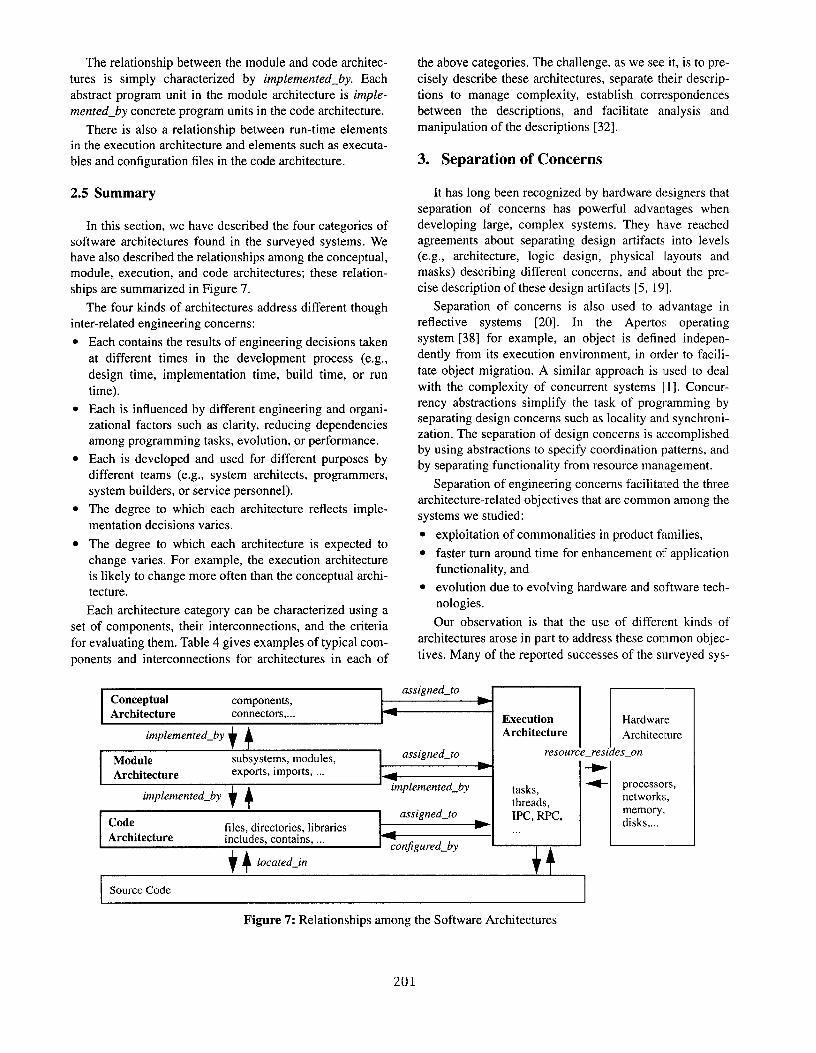
The execution architecture is a prominent part of the
software architecture of all of the surveyed systems. System
B illustrates a simple but typical example of an execution
architecture (Figure 5). Each application module from the
module architecture is assigned to its own operating system
task, and sometimes a module is replicated by having mttlti-
ple instantiation of its associated task. For example, the
Data Acquisition task is replicated once for each remote
sensor group. The real-time operating system provides the
queues, semaphores, and mailboxes that are used for inter-
process communication between tasks. Tasks, acting as pro-
ducers or consumers, use both synchronous and asynchro-
nous communication to exchange data. Figure 5 is derived
from the detailed diagram of the execution architecture.
More information about the interactions among the tasks is
shown using control and data flow diagrams. The paths arenumbered to reference accompanying text that describes the
order of communication among the tasks. These diagrams
are similar to object interaction diagrams used in object-ori-
ented analysis [18].
The relationship between the conceptual and execution
architectures is two fold. Fh-st, each conceptual component
or a connector (or its implementation) can be related to a
run-time element in the execution architecture using the
relation as~igned_to, Second, the communication mecha-
nisms selected in the execution architecture constrain the
vSystem B
!2includefiles
Rm
@@
E!iiYi!m
Figure 6: Code Architecture of System B
implementation of conceptual components and connec-
tors. In System B, for example, the selection of the operat-
ing system and communication mechanisms constrains
how the data acquisition connector is implemented.
The relationship between module and execution archi-
tectures is similar. Modules in the module architecture are
assigned_to run-time elements in the execution architec-
ture. In addition, each of the run-time elements in the exe-
cution architecture is implemented_by specific modules in
the module architecture.
2.4 Code Architecture
The code architecture is used to organize the source
code into language level modules, directories, files, and
libraries. This architecture is influenced by the choice of
the programming language, the development tools and
environment (e.g., configuration management), and the
structure of the project (e.g., inter-corporation) and the
organization. Although this architecture is explicit in all
the surveyed systems, it is generally not described as part
of the software architecture. We found that the major use
of this architecture is to facilitate system building, system
installation, and configuration management. Other uses are
to minimize dependencies (e.g., compilation) among sub-
projects and to enforce import/export constraints specifiedin the module architecture.
For System B, the organization of the source code mir-
rors the functional decomposition of the module architec-
ture of the application. The code architecture (Figure 6)
consists of directories for include files (defining inter-
faces), common library functions and source code. The
include files and libraries for the application and system
soft ware are separated.
200
The relationship between the module and code architec-
tures is simply characterized by implemented_by. Each
abstract program unit in the module architecture is imple-
mented_by concrete program units in the code architecture.
There is also a relationship between run-time elements
in the execution architecture and elements such as executa-
ble and configuration files in the code architecture.
2.5 Summary
In this section, we have described the four categories of
software architectures found in the surveyed systems. We
have also described the relationships among the conceptual,
module, execution, and code architectures; these relation-
ships are summarized in Figure 7.
The four kinds of architectures address different though
inter-related engineering concerns:
●
●
●
●
●
Each contains the results of engineering decisions taken
at different times in the development process (e.g.,
design time, implementation time, build time, or run
time).
Each is influenced by different engineering and organi-
zational factors such as clarity, reducing dependencies
among programming tasks, evolution, or performance.
Each is developed and used for different purposes by
different teams (e.g., system architects, programmers,
system builders, or service personnel).
The degree to which each architecture reflects imple-
mentation decisions varies.
The degree to which each architecture is expected to
change varies. For example, the execution architecture
is likely to change more often than the conceptual archi-
tecture.
Each architecture category can be characterized using a
set of components, their interconnections, and the criteria
for evaluating them. Table 4 gives examples of typical com-
ponents and interconnections for architectures in each of
, 4
the above categories. The challenge, as we see it, is to pre-
cisely describe these architectures, separate their descrip-
tions to manage complexity, establish correspondences
between the descriptions, and facilitate analysis and
manipulation of the descriptions [32].
3. Separation of Concerns
It has long been recognized by hardware designers that
separation of concerns has powerful advantages when
developing large, complex systems. They have reached
agreements about separating design artifacts into levels
(e.g., architecture, logic design, physical layouts and
masks) describing different concerns, and about the pre-
cise description of these design artifacts [5, 19].
Separation of concerns is also used to advantage in
reflective systems [20]. In the Apertos operating
system [38] for example, an object is defined indepen-
dently from its execution environment, in orcler to facili-
tate object migration. A similar approach is used to deal
with the complexity of concurrent systems [ 1]. Concur-
rency abstractions simplify the task of programming by
separating design concerns such as locality and synchroni-
zation. The separation of design concerns is accomplished
by using abstractions to specify coordination patterns, and
by separating functionality from resource management.
Separation of engineering concerns facilitated the three
architecture-related objectives that are common among the
systems we studied:
exploitation of commonalities in product families,
faster turn around time for enhancement of application
●
functionality, and
evolution due to evolving hardware and software tech-
nologies.
Our observation is that the use of different kinds of
architectures arose in part to address these common objec-
tives, Many of the reported successes of the surveyed sys-
I Conceptual I.—
components, w IIExecution Hardware
implemented_by+4 ,
Architecture Architecture
Module subsystems, modules, assigned_to resourc e_resides_on
*Architecture exports, imports, ...
~
implemented_by tasks,
+
,, ‘L-+processors,implemented_by
threads,networks,
Codeassigned_to IPC, RPC,
memory,,
files, directories, libraries disks,...Architecture includes, contains, ...
.,.
conjigured_by
Hlocated_in
Source Code
Figure 7: Relationships among the Software Architectures
201
Software Components Interconnections Engineering Criteria
Architecture
Conceptual domain-specific domain-specific constraints on cycles, requirements on throughput
Architecture components interconnections
Module systems, subsystems, component_of, import_from, functional decomposition methods, criteria such as
Architecture modules, layers export_to information hiding and abstraction, when to use muki-
ple interfaces, constraints imposed by layering strategy
Execution processes, tasks, threads, inter-process communication, criteria for priority assignment, constraints imposed by
Architecture clients, servers, buffers, remote procedure call run-time environment
message queues
Code files, directories, linker member_of, includes, contains, compilation and build time, criteria related to project
Architecture libraries, packages, linked_with, compiled_into, management and configuration management tools and
program libraries with clause, use clause the development environment
Table 4: Characterizations of the Software Architectures
terns resulted from allowing the different architectures to
develop independently while maintaining the relationship
between them. Similarly, some of the problems they
reported were a direct result of merging or intermingling
these architectures.
In Section 2, we described the typical software architec-
tures found in the surveyed systems. Next we describe
some of the more elegant examples of software architec-
tures, and the advantages of separating them.
3.1 Conceptual and Execution Architecturesin System G
The architecture of System G has an explicit conceptual
architecture. One of the design goals for this system is to
have a formal (i.e., complete and unambiguous) representa-
tion that both serves as documentation for the users, and
allows verification by engineers of various disciplines.
Such verification may include verification against the sys-
tem requirements, checking syntactic consistency, and vali-
dation with a system simulator.
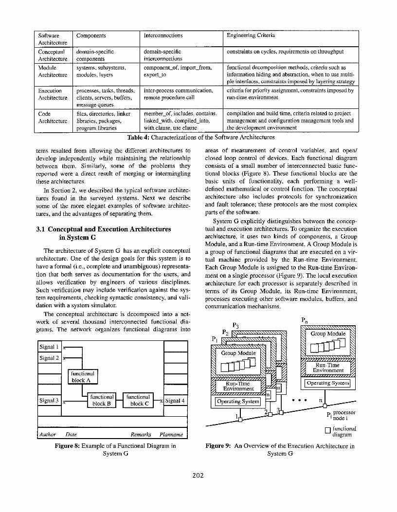
The conceptual architecture is decomposed into a net-
work of several thousand interconnected functional dia-
grams. The network organizes functional diagrams into
Author Date Remarks Planname
Figure 8: Example of a Functional Diagram in
System G
areas of measurement of control variables, and open/
closed loop control of devices. Each functional diagram
consists of a small number of interconnected basic func-
tional blocks (Figure 8). These functional blocks are the
basic units of functionality, each performing a well-
defined mathematical or control function. The conceptual
architecture also includes protocols for synchronization
and fault tolerance; these protocols are the most complex
parts of the software.
System G explicitly distinguishes between the concep-
tual and execution architectures. To organize the execution
architecture, it uses two kinds of components, a Group
Module, and a Run-time Environment. A Group Module is
a group of functional diagrams that are executed on a vir-
tual machine provided by the Run-time Environment.
Each Group Module is assigned to the Run-time Environ-
ment on a single processor (Figure 9). The local execution
architecture for each processor is separately described in
terms of its Group Module, its Run-time Environment,
processes executing other software modules, buffers, and
communication mechanisms.
Figure 9: An Overview of the Execution Architecture in
System G
202
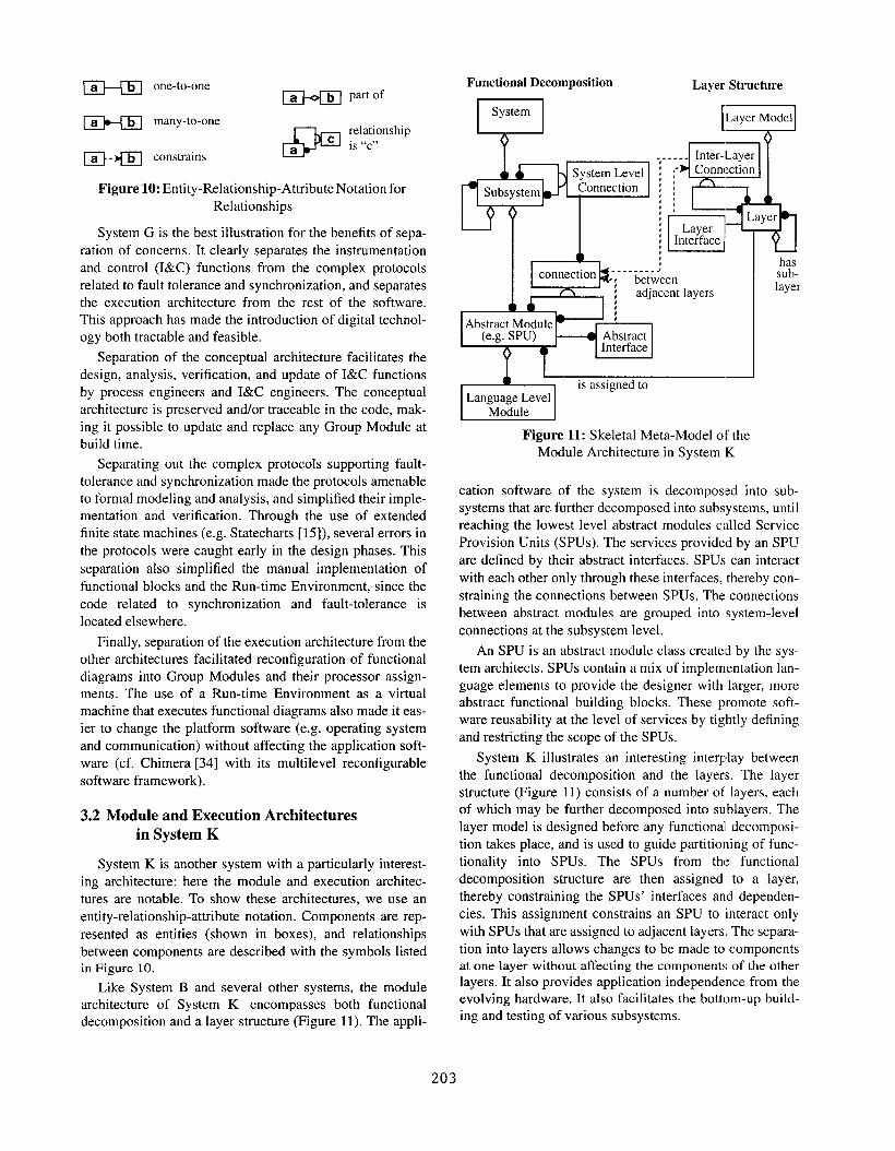
~ one-to-one~ part of
~ many-to-one
*
relationshipc is ‘<c,,
~-~ constrainsa
Figure 10: Entity -Relationship-Attribute Notation for
Relationships
System G is the best illustration for the benefits of sepa-
ration of concerns. It clearly separates the instrumentation
and control (I&C) functions from the complex protocols
related to fault tolerance and synchronization, and separates
the execution architecture from the rest of the software.
This approach has made the introduction of digital technol-
ogy both tractable and feasible.
Separation of the conceptual architecture facilitates the
design, analysis, verification, and update of I&C functions
by process engineers and I&C engineers. The conceptual
architecture is preserved and/or traceable in the code, mak-
ing it possible to update and replace any Group Module at
build time.
Separating out the complex protocols supporting fault-
tolerance and synchronization made the protocols amenable
to formal modeling and analysis, and simplified their imple-
mentation and verification. Through the use of extended
finite state machines (e.g. Statecharts [15]), several errors in
the protocols were caught early in the design phases. This
separation also simplified the manual implementation of
functional blocks and the Run-time Environment, since the
code related to synchronization and fault-tolerance is
located elsewhere.
Finally, separation of the execution architecture from the
other architectures facilitated reconfiguration of functional
diagrams into Group Modules and their processor assign-
ments. The use of a Run-time Environment as a virtual
machine that executes functional diagrams also made it eas-
ier to change the platform software (e.g. operating system
and communication) without affecting the application soft-
ware (cf. Chimera [34] with its multilevel reconfigurable
software framework).
3.2 Module and Execution Architectures
in System K
System K is another system with a particularly interest-
ing architecture: here the module and execution architec-
tures are notable. To show these architectures, we use an
entity -relationship-attribute notation. Components are rep-
resented as entities (shown in boxes), and relationships
between components are described with the symbols listedin Figure 10.
Like System B and several other systems, the module
architecture of System K encompasses both functional
decomposition and a layer structure (Figure 11). The appli-
Functional Decomposition Layer Structure
uSystemlLayer~ll
——
-
~Jis assigned to
Language LevelModule
Figure 11: Skeletal Mets-Model of the
Module Architecture in System K
cation software of the system is decomposed into sub-
systems that are further decomposed into subsystems, until
reaching the lowest level abstract modules called Service
Provision Units (SPUS). The services provided by an SPU
are defined by their abstract interfaces. SPUS can interact
with each other only through these interfaces, thereby con-
straining the connections between SPUS. The connections
between abstract modules are grouped into system-level
connections at the subsystem level.
An SPU is an abstract module class created by the sys-
tem architects. SPUS contain a mix of implementation lan-
guage elements to provide the designer with larger, more
abstract functional building blocks. These promote soft-
ware reusability at the level of services by tightly defining
and restricting the scope of the SPUS.
System K illustrates an interesting interplay between
the functional decomposition and the layers. The layer
structure (Figure 11) consists of a number of layers, each
of which may be further decomposed into sublayers. The
layer model is designed before any functional decomposi-
tion takes place, and is used to guide partitioning of func-
tionality into SPUS. The SPUS from the functional
decomposition structure are then assigned to a layer,
thereby constraining the SPUS’ interfaces and dependen-
cies. This assignment constrains an SPU to interact only
with SPUS that are assigned to adjacent layers. The separa-
tion into layers allows changes to be made to componentsat one layer without affecting the components of the other
layers. It also provides application independence from the
evolving hardware. It also facilitates the bottom-up build-
ing and testing of various subsystems.
203
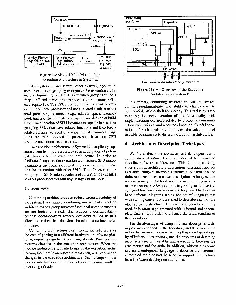
I IrActive Element Data Element Other
‘“h
Module(e.g. OS process (e.g. buffer, Resources Instance
or task) disk storage) (e.g. SPUinstance)
Figure 12: Skeletal Mets-Model of the
Execution Architecture in System K
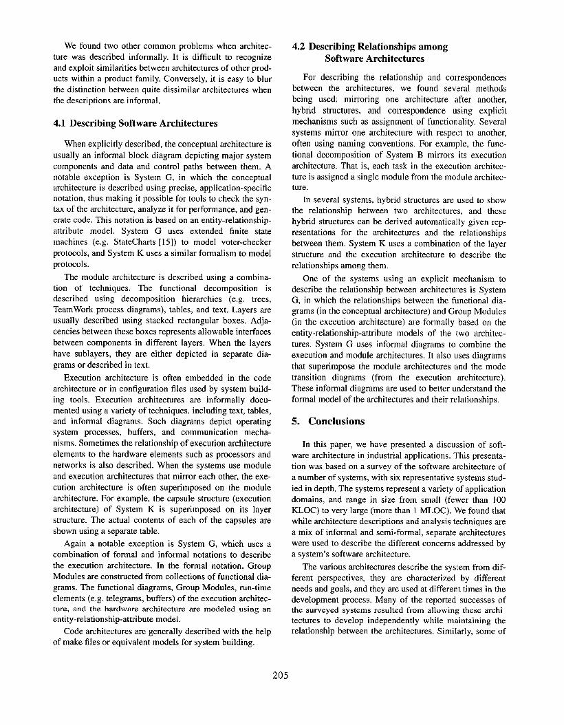
Like System G and several other systems, System K
uses an execution grouping to organize the execution archi-
tecture (Figure 12). System Ks execution group is called a
“capsule,” and it contains instances of one or more SPUS
(see Figure 13). The SPUS that comprise the capsule exe-
cute on the same processor and are allocated a subset of the
total processing resources (e.g., address space, memory
pool, timers). The contents of a capsule are defined at build
time. The allocation of SPU instances to capsule is based on
grouping SPUS that have related functions and therefore a
related cumulative need of computational resources. Cap-
sules are then assigned to processors based on CPU
resource and timing requirements.
The execution architecture of System K is explicitly sep-
arated from its module architecture in anticipation of poten-
tial changes to the execution architecture. In order to
facilitate changes to the execution architecture, SPU imple-
mentations use loosely-coupled inter-process communica-
tion for interaction with other SPUS. This allows alternate
grouping of SPUS into capsules and migration of capsules
to other processors without any changes to the code.
3.3 Summary
Combining architectures can reduce understandability of
the system. For example, combining module and execution
architectures can group together functional components that
are not logically related. This reduces understandability
because decomposition reflects decisions related to task
allocation rather than decisions based on functional rela-
tionships.
Combining architectures can also significantly increase
the cost of porting to a different hardware or software plat-form, requiring significant rewriting of code. Porting often
requires changes in the execution architecture. When the
module architecture is made to mirror the execution archi-
tecture, the module architecture must change in response to
changes in the execution architecture. Such changes in the
module interfaces and the process boundaries may result in
reworking of code.
Processingplatform Capsule i
I Capsule 1 Ai.rh
I . SPU m III ISPU1 nil.
B’ L II
I OS kernel !
Communication; with’ oth;r system units
Figure 13: An Overview of the Execution
Architecture in System K
In summary, combining architectures can limit evolv-
ability, reconfigurability, and ability to change over to
commercial, off-the-shelf technology. This is due to inter-
mingling the implementation of the functionality with
implementation decisions related to protocols, communi-
cation mechanisms, and resource allocation. Careful sepa-
ration of such decisions facilitates the adaptation of
reusable components to different execution architectures.
4. Architecture Description Techniques
We found that most architects and developers use a
combination of informal and semi-formal techniques to
describe software architectures. This is not surprising
since rigorous architecture description techniques are not
available. Entity -relationship-attribute (ERA) notation and
finite state machines are two description techniques that
were extremely useful for describing and modeling aspects
of architecture. CASE tools are beginning to be used to
construct functional decomposition diagrams. On the other
hand, informal diagrams, tables, and natural language text
with naming conventions are used to describe many of the
other software structures. Even when a formal notation is
used, it is often supplemented with informal and incom-
plete diagrams, in order to enhance the understanding of
the formal model.
The disadvantages of using informal description tech-niques are described in the literature, and this was borne
out in the surveyed systems. Among these are the ambigu-
ity of informal descriptions, and the problems of detecting
inconsistencies and establishing traceability between the
architecture and the code. In addition, without a rigorous
and an unambiguous language to describe architectures,
automated tools cannot be used to support architecture-
based software development activities.
204
We found two other common problems when architec-
ture was described informally. It is difficult to recognize
and exploit similarities between architectures of other prod-
ucts within a product family. Conversely, it is easy to blur
the distinction between quite dissimilar architectures when
the descriptions are informal.
4.1 Describing Software Architectures
When explicitly described, the conceptual architecture is
usually an informal block diagram depicting major system
components and data and control paths between them. A
notable exception is System G, in which the conceptualarchitecture is described using precise, application-specific
notation, thus making it possible for tools to check the syn-
tax of the architecture, analyze it for performance, and gen-
erate code. This notation is based on an entity-relationship-
attribute model. System G uses extended finite state
machines (e.g. StateCharts [15]) to model voter-checker
protocols, and System K uses a similar formalism to model
protocols.
The module architecture is described using a combina-
tion of techniques. The functional decomposition is
described using decomposition hierarchies (e.g. trees,
TeamWork process diagrams), tables, and text. Layers are
usually described using stacked rectangular boxes. Adja-
cencies between these boxes represents allowable interfaces
between components in different layers. When the layers
have sublayers, they are either depicted in separate dia-
grams or described in text.
Execution architecture is often embedded in the code
architecture or in configuration files used by system build-
ing tools. Execution architectures are informally docu-
mented using a variety of techniques, including text, tables,
and informal diagrams. Such diagrams depict operating
system processes, buffers, and communication mecha-
nisms. Sometimes the relationship of execution architecture
elements to the hardware elements such as processors and
networks is also described. When the systems use module
and execution architectures that mirror each other, the exe-
cution architecture is often superimposed on the module
architecture. For example, the capsule structure (execution
architecture) of System K is superimposed on its layer
structure. The actual contents of each of the capsules are
shown using a separate table.
Again a notable exception is System G, which uses a
combination of formal and informal notations to describe
the execution architecture. In the formal notation, Group
Modules are constructed from collections of functional dia-
grams. The functional diagrams, Group Modules, run-time
elements (e.g. telegrams, buffers) of the execution architec-ture, and the hardware architecture are modeled using an
entity-relation ship-attribute model.
Code architectures are generally described with the help
of make files or equivalent models for system building.
4.2 Describing Relationships among
Software Architectures
For describing the relationship and correspondences
between the architectures, we found several methods
being used: mirroring one architecture after another,
hybrid structures, and correspondence using explicit
mechanisms such as assignment of functionality. Several
systems mirror one architecture with respect to another,
often using naming conventions. For example, the func-
tional decomposition of System B mirrors its execution
architecture. That is, each task in the execution architec-
ture is assigned a single module from the module architec-ture.
In several systems, hybrid structures are used to show
the relationship between two architectures, and these
hybrid structures can be derived automatically given rep-
resentations for the architectures and the relationships
between them. System K uses a combination of the layer
structure and the execution architecture to describe the
relationships among them.
One of the systems using an explicit mechanism to
describe the relationship between architectures is System
G, in which the relationships between the functional dia-
grams (in the conceptual architecture) and Group Modules
(in the execution architecture) are formally based on the
entity-relationship-attribute models of the two architec-
tures. System G uses informal diagrams to combine the
execution and module architectures. It also uses diagrams
that superimpose the module architectures and the mode
transition diagrams (from the execution architecture).
These informal diagrams are used to better understand the
formal model of the architectures and their relationships.
5. Conclusions
In this paper, we have presented a discussion of soft-
ware architecture in industrial applications. This presenta-
tion was based on a survey of the software architecture of
a number of systems, with six representative systems stud-
ied in depth. The systems represent a variety of application
domains, and range in size from small (fewer than 100
KLOC) to very large (more than 1 MLOC). We found that
while architecture descriptions and analysis techniques are
a mix of informal and semi-formal, separate architectures
were used to describe the different concerns addressed by
a system’s software architecture.
The various architectures describe the system from dif-
ferent perspectives, they are characterized by different
needs and goals, and they are used at different times in the
development process. Many of the reported successes ofthe surveyed systems resulted from allowing these archi-
tectures to develop independently while maintaining the
relationship between the architectures. Similarly, some of
205
the problems they reported were a direct result of merging
or intermingling these architectures.
In examining the components and interconnections in
the systems, we found that the structures used to describe
architecture fall into four broad categories. The conceptual
architecture describes the structure of a system in terms of
its functional components and interface connectors, the
module architecture describes the ideal implementation
structure of the system, the execution architecture describes
the dynamic structure of a system in terms of its run-time
elements, and the code architecture describes how the
source code of the system is organized.
While these categories are not the final answer to the
definition of software architecture, we believe that separat-
ing structures into more than one perspective is crucial.
This separation accurately reflects the practice in develop-
ment of real software systems, and the reasons for the sepa-
ration become clear upon studying these systems.
We believe this separation of software architectures will
facilitate the use of formal approaches (such as formal
description and analysis) that are powerful, but have not
readily produced scalable, practical results. Meanwhile, rig-
orous techniques need to be developed to describe these
software architectures, so that they can be analyzed to pre-
dict and assure non-functional system properties. It then
becomes possible to design, implement, test, and re-engi-
neer a software system based on the rigorous description of
its architecture. Finally, all of these architecture-based
activities need to be incorporated in existing development
processes for maximum effectiveness.
Acknowledgments
We thank all of the architects and developers of the sys-
tems we surveyed for their time and patience. We also thank
Amitava Datta, Paul Drongowski, Igor Gordon, and L1ang
Hsu for valuable suggestions.
References
[1]
[2]
[3]
[4]
[5]
G. Agha, P. Wegner, and A. Yonezawa (eds.). Research
Directions in Concurrent Object-Oriented Programming,
The MIT Press, 1993.
R. Allen and D. Garlan. A formal approach to software
architectures, Algorithms, Software, Architecture, J. vanLeeuwen (editor), Information Processing 92, Volume 1,
Elsevier Science Publishers B.V. (North-Holland), 1992.
M.R. Barbacci, C.B. Weinstock, and J.M. Wing. Program-
ming at the processor-memory-switch level. In Proceedings
of the 10th International Conference on Software Engineer-
ing, IEEE Computer Society Press, pages 19-28, April 1988.
B.W. Beach. Connecting software components with declara-
tive glue, In Proceedings of the Fourteenth International
Conference on Software Engineering, 1992.
C.G. Bell and A. Newell. Computer Structures: Readings
and Examples, McGraw-Hill, 1971.
[6]
[7]
[8]
[9]
[10]
[11]
[12]
[13]
N. Delisle and D. Garlan. A formal specification of an
oscilloscope, IEEE Software, pages 29-36, September
1990.
F. DeRemer and H. Kron. Programming-in-the-large ver-
sus programming-in-the-small. IEEE Transactions orr Soft-
ware Engineering, SE-2 (2): 80-86, June 1976.
R. D’Ippolito and K. Lee. Modeling Software Systems by
Domains, AAAI-92 Workshop on Automating Sof~are
Design, July 1992.
P.J. Drongowski. Software architectures in real-time sys-
tems. In Proceedings of the First Workshop on Real-Time
Applications, IEEE Computer Society, May 1993.
M.S. Feather and A. van Lamsweerde. Succeeding of the
Seventh International Workshop on Software Specification
and Design. Software Engineering Notes, 19 (3): 18-22,
July 1994.
P. Feiler. Configuration management models in commercial
environments. Technical Report CMWSEI-91 -TR-7, Carn-
egie Mellon University, 1991.
S.1. Feldman. Make - a program for maintaining computer
programs. Soflware - Practice and Experience, 9:255-265,
November 1979.
H.D. Fischer. Special features of a computer-based German
reactor protection system, in Proceedings of Fault-Tolerant
Computing Systems, Springer-Verlag, Nurnberg, pp. 266-
287, September 1991.
[14] D. Garlan and M. Shaw. An introduction to software archi-
tecture, in Advances in Software Engineering and KnowG-
edge Engineering, V. Ambriola and G. Tortora (editors),
Vohrme 1, World Scientific Publishing Company, New Jer-
sey, 1993.
[15] D. Hare]. Statecharts: A visual formalism for complex sys-
tems, Science of Computer Programming, Volume 8, pages
231-274, 1987.
[16] D.J. Hatley and I.A. Pirbhai. Strategies for Real-Time Sys-
tem Specification, Dorset House Publishing, New York,
1988.
[17] C.H. Hoogendoorn and A.T. Maher. Enhanced software
architecture for an ATM universal communication node,
Proceedings of the 14th International Switching Sympo-
sium, Yokohama, Japan, October 1992.
[18] I. Jacobsen et al. Object-Oriented Software Engineering -
A Use Case Driven Approach, Addison-Wesley, 1992.
[19] R.H. Katz, Information Management for Engineering
Design, Springer-Verlag, 1985.
[20] G. Kiczales, J. des Rivieres, and D.G. Bobrow. The Art of
the Metaobject Protocol, The MIT Press, 1991.
[21] J. Kramer. Configuration programming - a framework for
the development of distributable systems, In Proceedings
of the IEEE International Conference on Computer Sys-
tems and Soflware Engineering, Israel, IEEE, May 1990.
[22] R. Lange, R.W. Schwanke. Software architecture analysis:
A case study. In Proceedings of the Third International
Workshop on Soflware Configuration Management, Trond-
heim, Norway, ACM Press, June 1991.
[23] E. Mettala and M.H. Graham. The domain-specific soft-
ware architecture program, Technical Report, CMU/SEI-
206
[24]
[25]
[26]
[27]
[28]
[29]
[30]
[31]
[32]
[33]
[34]
[35]
[36]
[37]
[38]
92-SR-9, Carnegie Mellon University, Software Engineer-
ing Institute, June 1992.
K. Narayanaswamy and W. Scacchi. Maintaining configura-
tions of evolving software systems. IEEE Transactions on
.Software Engineering, SE-13(3), March 1987.
D.E. Perry and A.L. Wolf. Foundations for the study of soft-
ware architecture, ACM SIGSOFT Software Engineering
Notes, Volume 17, Number 4, pages 40-52, October 1992.
R. Prieto-Diaz and J.M. Neighbors. Module interconnection
languages. The Journal of Systems and Software, 6(4):307-
334, November 1986.
J.M. Purtilo. The polylith software bus. To appear, ACM
Transactions on Programming Languages and Systems, Jan-
uary 1994. Also available as Technical Report UMIACS-
TR-90-65, University of Maryland, May 1990.
W. Royce. TRW’s Ada process model for incremental devel-
opment of large software systems. In Proceedings oj the
12th International Conference on Software Engineering,
IEEE Computer Society Press, pages 2-11, March 1990.
J. Schaeffer, D. Szafron, G. Lobe, I. Parsons. The Enterprise
model for developing distributed applications, Dept. of
Computing, University of Alberta, 1993.
B. Selic, G. Gullekson, J, McGee, and I. Engelberg. ROOM:
an object-oriented methodology for developing real-time
systems, In Proceedings of the CASE’92 Ft~th International
Workshop on Computer-Aided Software Engineering, Mont-
real, Canada, July 1992.
M. Shaw. Larger scale systems require higher level abstrac-
tions, in Proceedings of the Ftfth International Workshop on
Software Specification and Design, IEEE Computer Society,
pages 143-146, May 1989.
D. Soni, R.L. Nerd, L. Hsu, 1? Drongowski. Many faces of
software architectures, In Proceedings of the Workshop on
Studies of Soflware Design, Baltimore, May 1993 (to appear
in LNCS).
D. Soni, R.L. Nerd, L. Hsu. An empirical approach to soft-
ware architectures, in Proceedings of the Seventh Interna-
tional Workshop on Software Specification and Design,
IEEE Computer Society, December 1993.
D.B. Stewart, R.A. Volpe, and P.K. Khosla. Integration of
software modules for reconfigurable sensor-based controlsystems, In Proceedings of 1992 IEEE/RSJ International
Conference on Intelligent Robots and Systems (IROS ‘92),
Raleigh, North Carolina, July 1992.
W. Tlchy. Software development control based on module
interconnection. In Proceedings of the Third International
Conference on So@ware Engineering, pages 29-41, IEEEComputer Society Press, May 1979.
M. Weiser. Source Code, IEEE Computer, pages 66-73,
November 1987.
A. Wolf. Language and tool support for precise interface
control. Technical Report COINS-TR-85-23, University of
Massachusetts, 1985.
Y. Yokote. The Apertos reflective operating system: the con-
cept and its implementation, In Proceedings of 00PSLA ’92,
pages 414-434, October 1992.
A Process forthe Study
The software systems we studied were all developed
for industrial applications. Although the designers and
developers of the various systems may disagree on exactly
what the software architecture consists of, they all recog-
nize its importance, and some are at the lealding edge in
their use of software architecture in industry, As a part of
the study, we talked to architects and engineers, read
design documents, and, in some cases, read parts of the
source code. The sequence of steps we undertook is as fol-
lows:
1.
2.
3.
4.
5.
6.
7.
8.
We started with an initial list of questions to guide our
study. The questions were related to how architecture
was described and used in the development of a sys-
tem. We developed a questionnaire based on these
questions and sent it to the organizations we intended
to visit. This questionnaire appears in Appendix B.
We visited the organizations to present our premise
and the objectives of our study.
We collected and read design documents and, in some
cases, code for the systems,
We held extended discussions with the architects and
designers of these systems. In some cases, these dis-
cussions lasted several days over several visits. We
used the questionnaire during these interviews to struc-
ture the initial discussion and to gather information.
We also held a workshop on software architectures
where the architects described and discussed the archi-
tecture of their systems.
We selected six of the systems for more detailed study,
and carefully studied the available artifacts for these
systems. These six, annotated with asterisks in Table 1,
represent a wide variety of application domains, and
they are among the systems for which we Ihad the most
information.
We distilled the information from these six systems
using a structured template. This template appears in
Appendix C.
We analyzed the distilled information to m-rive at our
findings. Based on this analysis, we restructured the
description of the systems to improve understanding,
and prepared the internal technical report.
We then sent the technical report to the designers and
architects of the systems for their comments, and mod-
ified it based on these comments. The internal report
provides the basis for this paper.
207