Embed Size (px)
Citation preview

Software ArchitecturePerspectives on an Emerging Discipline
CS 532 Software DesignChapter Three
Learning Objective...to validate the Software Architectural Styles given in the prior chapter.
Seven examples illustrate how we can use architectural principles.Lets (1) consider how solutions to the same problems provide different
benefits; (2) get experience developing a domain specific style for afamily of industrial products; (3) find out how to apply a process-
control style to system design; and (4) see examples of heterogeneousarchitectures to understand why they were architected in such a way.
Frederick T Sheldon
Assistant Professor of Computer Science University of Colorado at Colorado Springs

© F.T. Sheldon
Univ. of Colorado at Colorado Springs
2
Chapter ThreeCase Studies in Architectural Design⊗ Criteria for decomposing a system into modules
(components or sub-units)⊕ Functional with shared access to data (representations)
⊕ Hiding design decisions
⊗ PREMISE: Different problem decomposition strategies vary greatly in theirability to withstand design changes É changes in the
⊕ Algorithm,⊕ Data representation,⊕ Enhancements to system functions,⊕ Performance (time and space) and⊕ Reuse
© F.T. Sheldon
Univ. of Colorado at Colorado Springs
3
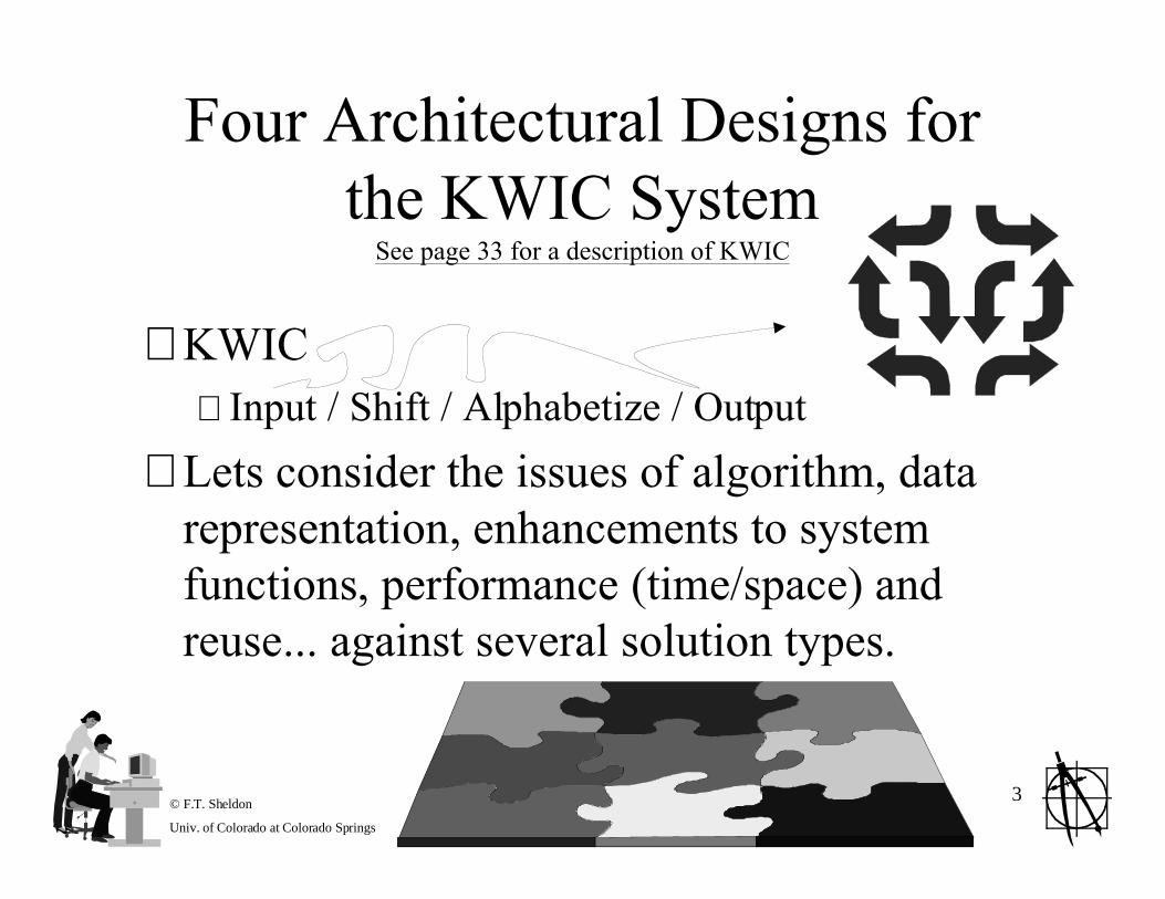
Four Architectural Designs forthe KWIC System
See page 33 for a description of KWIC
⊗ KWIC⊕ Input / Shift / Alphabetize / Output
⊗ Lets consider the issues of algorithm, datarepresentation, enhancements to systemfunctions, performance (time/space) andreuse... against several solution types.
© F.T. Sheldon
Univ. of Colorado at Colorado Springs
4
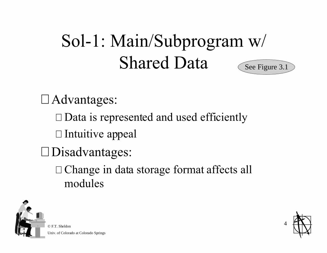
Sol-1: Main/Subprogram w/Shared Data
⊗ Advantages:⊕ Data is represented and used efficiently
⊕ Intuitive appeal
⊗ Disadvantages:⊕ Change in data storage format affects all
modules
See Figure 3.1
© F.T. Sheldon
Univ. of Colorado at Colorado Springs
5
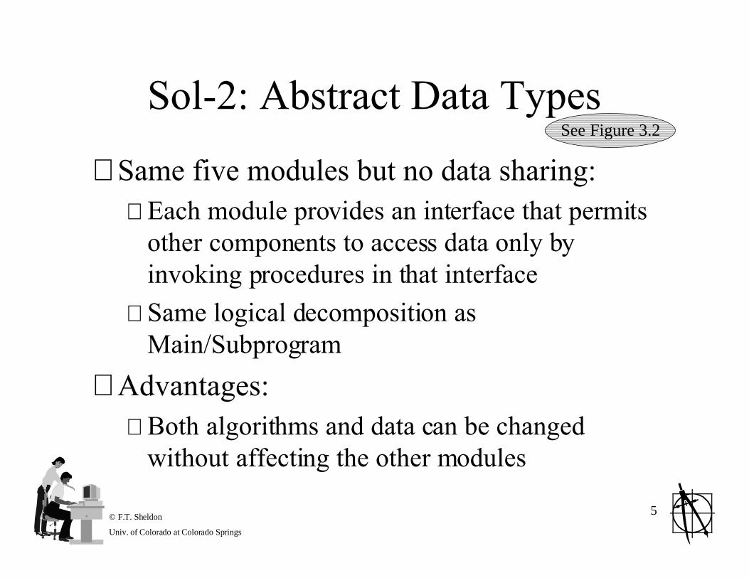
Sol-2: Abstract Data Types
⊗ Same five modules but no data sharing:⊕ Each module provides an interface that permits
other components to access data only byinvoking procedures in that interface
⊕ Same logical decomposition asMain/Subprogram
⊗ Advantages:⊕ Both algorithms and data can be changed
without affecting the other modules
See Figure 3.2

© F.T. Sheldon
Univ. of Colorado at Colorado Springs
6
Sol-2: Abstract Data Types
⊗ Advantages (continued)⊕ Reuse is supported:
¥ Modules make fewer assumptions about the others
⊗ Disadvantages⊕ Not well suited for certain kinds of functional
enhancements¥ Modifying existing modules may compromise their
simplicity or
¥ Adding new modules may lead to performance penalties
Continued
© F.T. Sheldon
Univ. of Colorado at Colorado Springs
7
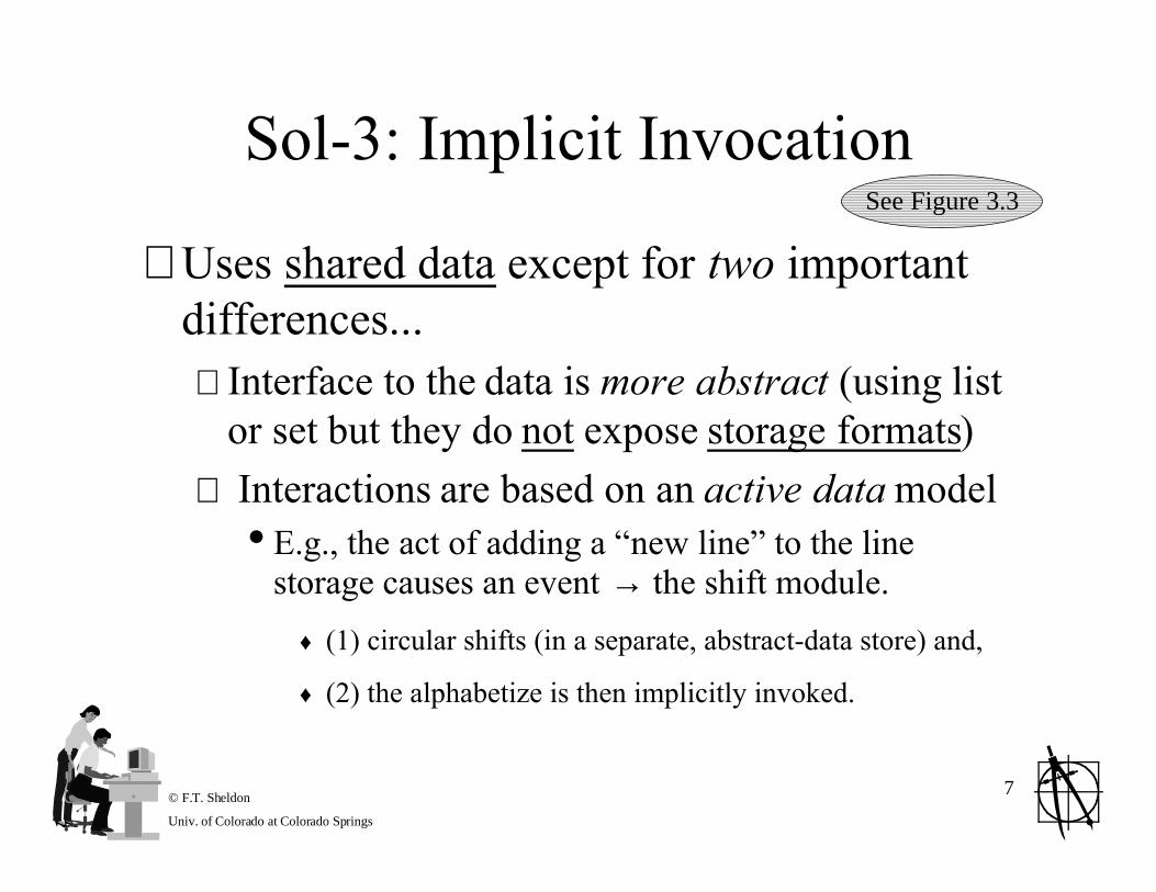
Sol-3: Implicit Invocation
⊗ Uses shared data except for two importantdifferences...⊕ Interface to the data is more abstract (using list
or set but they do not expose storage formats)
⊕ Interactions are based on an active data model¥ E.g., the act of adding a Ònew lineÓ to the line
storage causes an event → the shift module.
♦ (1) circular shifts (in a separate, abstract-data store) and,
♦ (2) the alphabetize is then implicitly invoked.
See Figure 3.3

© F.T. Sheldon
Univ. of Colorado at Colorado Springs
8
Sol-3: Implicit Invocation
⊗ Advantages⊕ Supports functional enhancement...
¥ Additional modules can be registered so that they willbe invoked by data changing events.
⊕ Insulates computations (data is accessedabstractly) from changes in data representation
⊕ Supports reuse¥ Implicitly invoked modules rely only on the existence
of certain externally triggered events → de-couplesmodules from each other!
Continued

© F.T. Sheldon
Univ. of Colorado at Colorado Springs
9
Sol-3: Implicit Invocation
⊗ Disadvantages⊕ Invocations are data driven and therefore:
¥ Difficult to control the processing order
¥ Most natural implementations of this kind tend touse more space!
Continued
© F.T. Sheldon
Univ. of Colorado at Colorado Springs
10
Sol-4: Pipes and Filters
⊗ Uses four filters working in a sequence
⊗ Control is distributed⊕ Filters run when input data is available
⊕ No data sharing except the piped data stream
⊗ Desirable properties (advantages)⊕ Maintains the intuitive flow of processing
⊕ Supports reuse¥ Each filter can function in isolation
¥ New functions easily added by inserting filters at theappropriate points in the processing sequence
See Figure 3.4

© F.T. Sheldon
Univ. of Colorado at Colorado Springs
11
Sol-4: Pipes and Filters
⊗ Disadvantages⊕ Virtually impossible to modify the design to
support interactive system
⊕ Deleting a line would some persistent sharedstorage¥ Violates a basic tenet of this approach
⊕ Uses space inefficiently¥ Filters copy all the to its input port
Continued

© F.T. Sheldon
Univ. of Colorado at Colorado Springs
12
Comparisons⊗ Shared data supports
⊕ Change in function and performance
⊗ ADTs supports⊕ Change in data representation, performance and
reuse
⊗ Implicit invocation supports⊕ Change in algorithm and function
⊗ Pipe and filter supports⊕ Reuse and change in function + algorithm
© F.T. Sheldon
Univ. of Colorado at Colorado Springs
13
Comparisons Must be Cognizant ofCertain Design Considerations
⊗ Intended use⊕ Batch versus interactive
⊕ Update intensive versus query-intensive
⊕ For example: Pipes and filter solution¥ Easily allows insertion of new filters (supports
changes in algorithm, function and reuse) but the datarepresentation is wired into assumptions about thekind of data that is transmitted along the pipes!
¥ Additional overhead may also involve the parsing andun-parsing of the data into pipes
© F.T. Sheldon
Univ. of Colorado at Colorado Springs
14
Instrumentation SoftwareCase Study
⊗ Purpose: develop a reusable systemarchitecture for oscilloscopes⊕ Functionality and features
¥ Performs dozens of measurements
¥ Megabytes of internal storage
¥ Interface to a network of workstations & instruments
¥ Sophisticated user interface:♦ Touch panel screen
♦ Built-in help facilities
♦ Color displays
© F.T. Sheldon
Univ. of Colorado at Colorado Springs
15
The Problems⊗ Legacy of heterogeneous conventions and
programming languages across the company
⊗ Rapidly changing market demands
⊗ Need to meet the demands of specialized markets⊕ General purpose → patient monitoring → automotive
diagnostics
⊗ Performance was suffering because⊕ Different operational modes were satisfied by loading
different software which was getting larger and larger

© F.T. Sheldon
Univ. of Colorado at Colorado Springs
16
The Goals and Results⊗ Develop and architectural framework that
would address these problems
⊗ Results:⊕ Domain specific SW architecture as a basis for
the next generation of oscilloscopes
⊕ The framework has been extended and adaptedto accommodate a broader class of systems
⊕ Also, refined to better suit the needs of theinstrumentation software!
© F.T. Sheldon
Univ. of Colorado at Colorado Springs
17
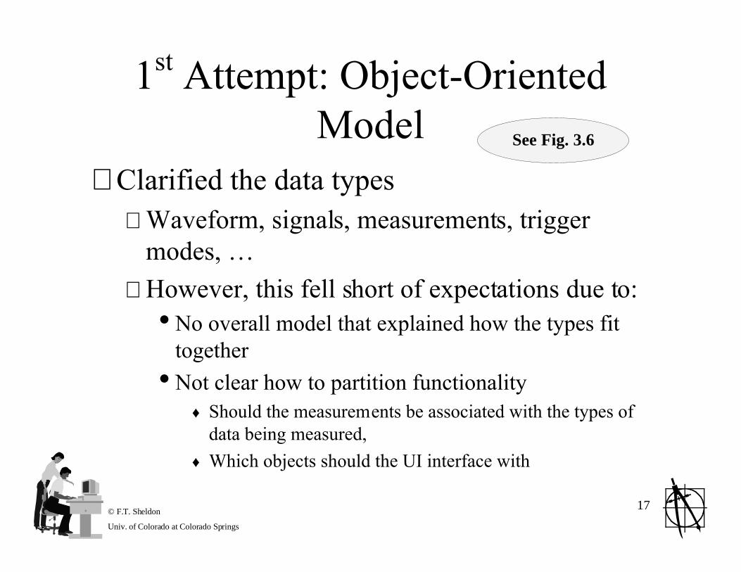
1st Attempt: Object-OrientedModel
⊗ Clarified the data types⊕ Waveform, signals, measurements, trigger
modes, É
⊕ However, this fell short of expectations due to:¥ No overall model that explained how the types fit
together
¥ Not clear how to partition functionality♦ Should the measurements be associated with the types of
data being measured,
♦ Which objects should the UI interface with
See Fig. 3.6
© F.T. Sheldon
Univ. of Colorado at Colorado Springs
18
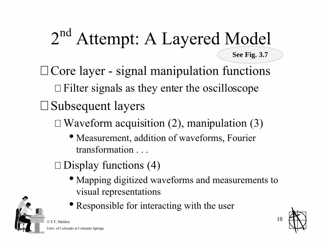
2nd Attempt: A Layered Model
⊗ Core layer - signal manipulation functions⊕ Filter signals as they enter the oscilloscope
⊗ Subsequent layers⊕ Waveform acquisition (2), manipulation (3)
¥ Measurement, addition of waveforms, Fouriertransformation . . .
⊕ Display functions (4)¥ Mapping digitized waveforms and measurements to
visual representations
¥ Responsible for interacting with the user
See Fig. 3.7
© F.T. Sheldon
Univ. of Colorado at Colorado Springs
19
2nd Attempt: A Layered Model→Debacle!
⊗ Layered models was intuitively appealing
⊗ Unfortunately. . .⊕ Wrong model for the application domain!
¥ The boundaries of abstraction enforced by layers conflictedwith the needs for interaction among various functions!
¥ Model suggested that all interactions with the user shouldbe with the visual representationÉbut,
¥ Real users need to directly affect the functions at all layers♦ E.g., setting attenuation at the signal manipulation layer, choosing
acquisition mode and parameters at the acquisition layer, etc.)

© F.T. Sheldon
Univ. of Colorado at Colorado Springs
20
3rd Attempt:Pipe and FilterModel
⊗ Functions viewed as incrementaltransformers of data⊕ Signal transformers used to condition external
signals
⊕ Acquisition transformers derive digitizedwaveforms from these signals
⊕ Display transformers convert these waveformsinto visual data
See Fig. 3.8
© F.T. Sheldon
Univ. of Colorado at Colorado Springs
21
Significant Improvement, Except...⊗ Functions were not isolated in separate partitions
⊕ Nothing prevents signal data from feeding directlyinto display filters
⊕ Model was intuitive wrt the engineers view of signalprocessing¥ Allowed clean intermingling and substitution of HW and
SW components within a system design!
⊕ However, one main problem was¥ Unclear how the user would interact with it!!!¥ User put simply at visual end → worse than layered model!
© F.T. Sheldon
Univ. of Colorado at Colorado Springs
22
4th Attempt:Modified Pipe andFilter Model
⊗ Accounts for the user inputs by associatingwith each filter a control interface⊕ Setting the sample rate, configuration
parameters
⊕ The filters were modeled as higher order (HO)functions
⊕ The HO functions determine what datatransformation the filter will perform
See Fig. 3.9

© F.T. Sheldon
Univ. of Colorado at Colorado Springs
23
Solved the UI Problem
⊗ ððProvided a collection of settings todynamically modify aspects of theoscilloscope characteristics⊕ Decoupled certain functions from the UI (as
was needed for the signal processing functions)
⊕ UI can treat the signal processing functionssolely in terms of the control parameters¥ Changes in the implementation SW/HW are possible
with out affecting the implementation of the UI

© F.T. Sheldon
Univ. of Colorado at Colorado Springs
24
Further Specialization Yet⊗ Still, performance was poor
⊕ Each time a filter needs to process a wave-formit copies a significantly large chunk of internalstorage!
⊕ Further, different filters run at radically differentspeeds! É A significant bottleneck
⊗ Solution was to introduce colors of pipes⊕ Some allowed processing w/o copying
⊕ Some allowed incoming data to be ignored
⊕ In all, tailoring of pipe/filter computations

© F.T. Sheldon
Univ. of Colorado at Colorado Springs
25
What Have We Learned
⊗ Seen some real issues
⊗ Emphasized the trade-offs
⊗ See that typical industrial SW must beadapted to the specific domains
⊗ The final result depended greatly on theproperties of the pipe and filter architectures
© F.T. Sheldon
Univ. of Colorado at Colorado Springs
26
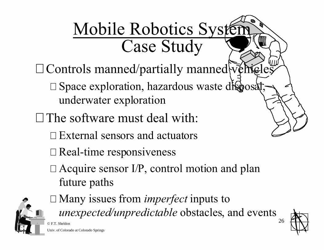
Mobile Robotics SystemCase Study
⊗ Controls manned/partially manned vehicles⊕ Space exploration, hazardous waste disposal,
underwater exploration
⊗ The software must deal with:⊕ External sensors and actuators
⊕ Real-time responsiveness
⊕ Acquire sensor I/P, control motion and planfuture paths
⊕ Many issues from imperfect inputs tounexpected/unpredictable obstacles, and events
© F.T. Sheldon
Univ. of Colorado at Colorado Springs
27
Design Considerations:Mobile Robots
⊗ Four basic requirements:⊕ Accommodate deliberate and reactive behavior
¥ Coordinate actions it must undertake to achieve its designatedobjective (collect rock sample, avoid obstacle)
⊕ Allow for uncertainty¥ Framework for actions even when faced with incomplete or
unreliable information (contradictory sensor readings)
⊕ Account for dangers¥ Must be fault tolerant, safe and with high performance (e.g., cope
with reduced power, dangerous vapors, etc.)
⊕ Give design flexibility¥ Development requires frequent experimentation and reconfiguration
© F.T. Sheldon
Univ. of Colorado at Colorado Springs
28
Lets Examine Four ArchitecturalDesigns
⊗ LozanoÕs Control Loops
⊗ ElfesÕs Layered Organization
⊗ SimmonsÕs Task Control Architecture
⊗ ShaferÕs Application of Blackboards
© F.T. Sheldon
Univ. of Colorado at Colorado Springs
29
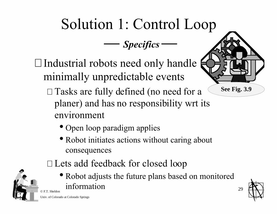
Solution 1: Control Loop Ñ Specifics Ñ
⊗ Industrial robots need only handleminimally unpredictable events⊕ Tasks are fully defined (no need for a
planer) and has no responsibility wrt itsenvironment¥ Open loop paradigm applies
¥ Robot initiates actions without caring aboutconsequences
⊕ Lets add feedback for closed loop¥ Robot adjusts the future plans based on monitored
information
See Fig. 3.9
© F.T. Sheldon
Univ. of Colorado at Colorado Springs
30
Solution 1: Control LoopRequirements Trade-Off Analysis
⊗ Req1Ð Advantage: simplicity⊕ Simplicity is a drawback in more unpredictable environments
⊕ Robots mostly confronted with disparate discrete events thatrequire them to switch between very different behavior modes
⊕ For complex tasks, gives no leverage for decomposition intocooperating components
⊗ Req2Ð Advantage: reducing unknowns through iteration⊕ Is biased toward one method (only).
⊕ Trial and error process of action-reaction to eliminate possibilitiesare each turn.
⊕ No framework for integrating these with the basic loop or fordelegating them to separate entities.

© F.T. Sheldon
Univ. of Colorado at Colorado Springs
31
Solution 1: Control LoopRequirements Trade-Off Analysis Continued
⊗ Req3Ð Advantage: supports fault tolerance and safety⊕ Simplicity makes duplication easy
⊕ Reduces the chance of errors creeping into the system
⊗ Req4 Ð Advantage: clearly partition-able into supervisor,sensors and motors that are independent and replaceable⊕ More refined tuning is however not really supported (inside the
modules)
⊗ Conclusion: Most appropriate for simple robotic systems
© F.T. Sheldon
Univ. of Colorado at Colorado Springs
32
Solution 2: Layered ArchitectureÑ Specifics Ñ

© F.T. Sheldon
Univ. of Colorado at Colorado Springs
33
© F.T. Sheldon
Univ. of Colorado at Colorado Springs
34
Solution 2: Layered ArchitectureRequirements Trade-Off Analysis
⊗ Req1⊕
⊗ Req2
⊗ Req3
⊗ Req4
© F.T. Sheldon
Univ. of Colorado at Colorado Springs
35
Solution 3: Implicit InvocationBasis and Specifics

© F.T. Sheldon
Univ. of Colorado at Colorado Springs
36

© F.T. Sheldon
Univ. of Colorado at Colorado Springs
37
Solution 3: Implicit InvocationRequirements Trade-Off Analysis
⊗ Req1⊕
⊗ Req2
⊗ Req3
⊗ Req4

© F.T. Sheldon
Univ. of Colorado at Colorado Springs
38
Solution 4: Blackboard Arch.Basis and Specifics

© F.T. Sheldon
Univ. of Colorado at Colorado Springs
39
© F.T. Sheldon
Univ. of Colorado at Colorado Springs
40
Solution 4: Blackboard Arch.Requirements Trade-Off Analysis
⊗ Req1⊕
⊗ Req2
⊗ Req3
⊗ Req4
© F.T. Sheldon
Univ. of Colorado at Colorado Springs
41
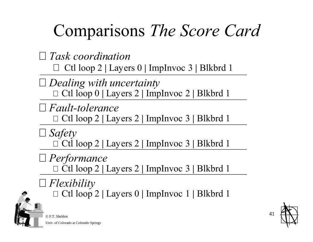
Comparisons The Score Card⊗ Task coordination
⊕ Ctl loop 2 | Layers 0 | ImpInvoc 3 | Blkbrd 1
⊗ Dealing with uncertainty⊕ Ctl loop 0 | Layers 2 | ImpInvoc 2 | Blkbrd 1
⊗ Fault-tolerance⊕ Ctl loop 2 | Layers 2 | ImpInvoc 3 | Blkbrd 1
⊗ Safety⊕ Ctl loop 2 | Layers 2 | ImpInvoc 3 | Blkbrd 1
⊗ Performance⊕ Ctl loop 2 | Layers 2 | ImpInvoc 3 | Blkbrd 1
⊗ Flexibility⊕ Ctl loop 2 | Layers 0 | ImpInvoc 1 | Blkbrd 1

© F.T. Sheldon
Univ. of Colorado at Colorado Springs
42

© F.T. Sheldon
Univ. of Colorado at Colorado Springs
43

© F.T. Sheldon
Univ. of Colorado at Colorado Springs
44
Cruise Control CaseStudy

© F.T. Sheldon
Univ. of Colorado at Colorado Springs
45
Three Vignettesin Mixed Style

© F.T. Sheldon
Univ. of Colorado at Colorado Springs
46

© F.T. Sheldon
Univ. of Colorado at Colorado Springs
47

© F.T. Sheldon
Univ. of Colorado at Colorado Springs
48

© F.T. Sheldon
Univ. of Colorado at Colorado Springs
49

© F.T. Sheldon
Univ. of Colorado at Colorado Springs
50

© F.T. Sheldon
Univ. of Colorado at Colorado Springs
51