Embed Size (px)
Citation preview
Software Architectures for Real-time Systems
Anders WallDepartment of Computer EngineeringMälardalen Real-Time research Center
Mälardalen UniversitySweden
[email protected] Technical Report 00/20, May 2000.
ABSTRACT
The solution to the complex nature of developing software is software engineering.Software engineering provides techniques for structured design, formal- and informalanalysis, and software metrics. The part of software engineering concerned with high-level design and analysis is called software architectures. The objective ofarchitectural analysis is to verify quality requirements on software. It can be appliedon any level in the design but it focuses on the structure of the software. While thearchitecture provides a high-level abstraction of the software, divergences betweenthe designed system and the requirements can be detected early in the design phase.However, the structure of the software alone does not always provide enoughinformation in order to analyze all requirements put upon a software system.Additional information about the software construction is provided by differentarchitectural views. The number of views, and their contents varies depending on thesystem domain and the required quality properties to analyze.
In this report, the state of the art in the field of software architectures is described.The survey is focused on software architectures for real-time systems but many of thedescribed techniques can be applied to general software systems.

2
3
Contents
1 Introduction ......................................................................................................................5
1.1 Towards a definition......................................................................................................6
1.2 Open research areas .....................................................................................................6
1.3 Outline ..........................................................................................................................7
2 Architecture description languages.................................................................................9
2.1 Desired properties of an architecture description language .......................................9
2.2 Semantics of an ADL ..................................................................................................10
2.3 Examples of existing architectural description languages.........................................11
3 Architectural views.........................................................................................................13
3.1 Discussions .................................................................................................................18
4 Architectural analysis ....................................................................................................19
4.1 Methods for architectural analysis .............................................................................19
4.2 Functional analysis ......................................................................................................21
4.3 Nonfunctional analysis ................................................................................................26
5 Architectural design .......................................................................................................31
5.1 An example .................................................................................................................32
6 Conclusions.....................................................................................................................35
7 References .......................................................................................................................37
Appendix A - Terminology ......................................................................................................41

4
5
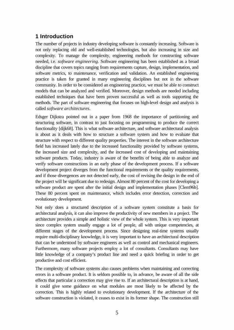
1 IntroductionThe number of projects in industry developing software is constantly increasing. Software isnot only replacing old and well-established technologies, but also increasing in size andcomplexity. To manage the complexity, engineering methods for constructing softwareneeded, i.e. software engineering. Software engineering has been established as a broaddiscipline that covers topics ranging from requirements capture, design, implementation, andsoftware metrics, to maintenance, verification and validation. An established engineeringpractice is taken for granted in many engineering disciplines but not in the softwarecommunity. In order to be considered an engineering practice, we must be able to constructmodels that can be analyzed and verified. Moreover, design methods are needed includingestablished techniques that have been proven successful as well as tools supporting themethods. The part of software engineering that focuses on high-level design and analysis iscalled software architectures.
Edsger Dijkstra pointed out in a paper from 1968 the importance of partitioning andstructuring software, in contrast to just focusing on programming to produce the correctfunctionality [dijk68]. This is what software architecture, and software architectural analysisis about as it deals with how to structure a software system and how to evaluate thatstructure with respect to different quality properties. The interest in the software architecturefield has increased lately due to the increased functionality provided by software systems,the increased size and complexity, and the increased cost of developing and maintainingsoftware products. Today, industry is aware of the benefits of being able to analyze andverify software constructions in an early phase of the development process. If a softwaredevelopment project diverges from the functional requirements or the quality requirements,and if those divergences are not detected early, the cost of revising the design in the end ofthe project will be significant due to redesign. Almost 80 percent of the cost for developing asoftware product are spent after the initial design and implementation phases [Clem96b].These 80 percent spent on maintenance, which includes error detection, correction andevolutionary development.
Not only does a structured description of a software system constitute a basis forarchitectural analysis, it can also improve the productivity of new members in a project. Thearchitecture provides a simple and holistic view of the whole system. This is very importantsince complex system usually engage a lot of people, all with unique competencies, atdifferent stages of the development process. Since designing real-time systems usuallyrequire multi-disciplinary knowledge, it is very important to have an architectural descriptionthat can be understood by software engineers as well as control and mechanical engineers.Furthermore, many software projects employ a lot of consultants. Consultants may havelittle knowledge of a company’s product line and need a quick briefing in order to getproductive and cost efficient.
The complexity of software systems also causes problems when maintaining and correctingerrors in a software product. It is seldom possible to, in advance, be aware of all the sideeffects that particular a correction may give rise to. If an architectural description is at hand,it could give some guidance on what modules are most likely to be affected by thecorrection. This is highly related to evolutionary development. If the architecture of thesoftware construction is violated, it ceases to exist in its former shape. The construction still
6
has an architecture, but as long as the architecture is not explicitly, and correctly described,it is of no use. Consequently, the architectural description may, and should, evolve as theconstruction that it describes evolves.
1.1 Towards a definition
There are almost as many definitions of software architecture in the literature as there aresoftware architects and designers. We mention a few examples:
The software architecture of a program or computing system is the structure orstructures of the system, which compromise software components, the external visibleproperties of those components, and the relationships among them [BCK98].
In [Paul94] the following definition is given:
Software architecture not only reflects how the functional requirements are met, butaddresses:
1. non-functional requirements
2. design rationale
3. architecture style
Yet another definition is provided in [Clem96a]:
A view of a system that includes the system’s major components, the behavior ofthose components as visible to the rest of the system, and the ways in which thecomponents interact and coordinate to achieve the system’s mission.
One property that seems to be common among almost every proposed definition is that thesoftware architecture describes a system by a composition of its software components andtheir interrelationships. In addition, software architectures should provide a high leveldescription, i.e. a more abstract level than the level that algorithms and data structureprovides. However, defining a software architecture only as a syntactical representations ofcomponents and their interconnections in the software systems is not sufficient. To be useful,additional information must be present in the description, in particular the semantics ofcomponents and connections. Different domains of software systems have differentsemantics of their software architectural description. A domain defines the class ofapplication to which a product belongs, e.g. desktop applications and industrial controlapplications. As a consequence, there will be variations in the definitions of softwarearchitectures depending on the domain. Furthermore, the definition also depends on the aimof the architectural description, e.g. support for architectural analysis, representation ordescription of the designed system. It is probably impossible to unify software designers inone single definition as it depends on the aim of the architecture and the domain in which it isused. What we can state is that software architecture is a description of the softwarestructure and methods to evaluate and compare design solutions.
1.2 Open research areas
As software architecture is an immature research area, a lot of open questions still exist.Most of the ongoing research in the field of software architectures is focused on descriptionlanguages and analysis of architectures for non-real-time systems. The analysis methods are
7
still informal in their nature. As the analysis methods are informal they provide rough metricsand estimations. We believe that formality can be added to architectural models. Thus, themodels can provide means for formal verification of some of the quality properties that arelisted in this survey.
Most of the material on software architectural analysis found in the literature ignores thetemporal aspects. By adding the temporal dimension on software, completely new problemarises. As an example, components developed for real-time systems, i.e. system for whichcorrectness depend on both the functionality and the temporal correctness, can not bereused in new environments unless at least the temporal constraints are still fulfilled. Qualityproperties such as flexibility, i.e. the ability of a software system to adopt new, or removeold functionality, are also important. As real-time systems are restricted to resources such asprocessors, communication busses, etc., a lot of additionally parameters must be taken intoaccount in such an analysis.
The tool support for architectural design and analysis is poor. Tools that support thecomplete process of developing an architecture are needed. Today, architectural tools forreal-time systems almost exclusively focus on schedulability analysis. As indicated in thisreport, there are a lot of other important properties of real-time systems software. However,implementing such tools is non-trivial. One approach is to use existing tools for automaticverification. This can be done if the problem of analyzing a specific quality property can betransformed into a property that can be verified using that tool. Examples of existing tools forformal verification are UPPAAL and KRONOS [LPY97][DaYo95].
1.3 Outline
Chapter 2 discusses architectural description languages and desired properties of such. InChapter 3, the architectural view necessary for an architectural analysis of real-time softwarearchitectures is discussed. Architectural analysis is dealt with in Chapter 4. Finally, Chapter5 concludes the report. Terminology used in the paper is explained as it is used. Appendix Aprovides, however, a complete list of the vocabulary together with a short explanation.

8
9
2 Architecture description languagesCommunication among software engineers is crucial. Without means for communication,important information into- and from the design phase might accidentally get lost, resulting inmisinterpretations. Moreover, a system designer must be able to communicate withcustomers, other project members and management in an unambiguous way. Anunambiguous architectural description is also a necessary condition for performingarchitectural analysis. A parable is the building trade, where building architects transform thecustomer requirements into a design. This design must be described in a way the buildingconstructor understands in order to do mechanical strength calculus and for building workersto use as a blueprint. When developing software, a software engineer formalizes thecustomer requirements. Based on the requirements, a high-level design is described in alanguage that is commonly understood by customers and designers. The common languageis a necessity in order to communicate and discuss design solutions. As output from the high-level design phase, one or several candidate architectural solutions are produced.
To verify that the quality requirements of the system are met by the architectural solutions,the architecture has to be analyzed. Hence, the description language used in the high-leveldesign must support the analysis methods. Once a software architecture is constructed thatfulfils the requirements, the architectural description is used as a ”blueprint” whenimplementing the system. In addition, an architectural description makes maintenance easiersince it facilitates the understanding how parts of software systems cooperate. Thus, theparts of a software system, i.e. components and sub-systems, affected by a correction aredetected in advance.
2.1 Desired properties of an architecture description language
Languages for architectural description are called Architecture Description Languages(ADL). There is an abundance of ADL:s, each of them with its own specific syntax,semantics, expressiveness and purposes[EHLS94][LKAV93][Vest94]. An ideal ADLshould however, provide six classes of properties: composition, abstraction, reusability,configuration, heterogeneity and analysis [SHGA96]. By composition is meant that asoftware system should be described as a composition of components and connections.Furthermore, components and connections must also be described in a way that clearly andexplicitly describes the exact role of each element, i.e. modeled on an appropriate level ofabstraction.
As components are reused in different applications that are described using differentdescription languages, the architectural description must be able to adopt to reuse. That is, itshould be possible to reuse components, connectors describing the interconnection betweencomponents and architectural patterns in different architectural descriptions. Related toreusability is heterogeneity. Heterogeneity is the possibility of combining differentheterogeneous architectural descriptions.
Configuration means that the architectural structure among components in the systemshould be separated from the structure in the components. The language should also supportdynamic reconfiguration. As will be discussed in Chapter 3, the structural view describes all
10
components and connections, whereas the module view unveils the structure of eachcomponent.
Finally, as high-level design analysis is one of the primer justifications for using softwarearchitectural techniques, the architectural description must support different kinds ofanalyses.
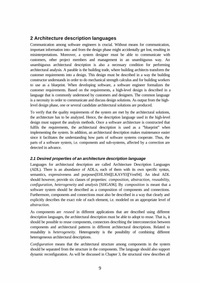
Considering the desired properties of an architectural description above, how can asoftware architecture be described? One possibility is a plain textural description in a naturallanguage. However, natural languages tend to be ambiguous, making them really hard tointerpret in a consistent manner. By using a formal language an unambiguous description isobtained. With formal languages it is possible to use mathematics when modeling andverifying the architecture. The disadvantage of using formal languages as architecturaldescriptions are that most of them requires a lot of experience and mathematical skill.Consequently, such a description may be sufficient and useful at some stage in the designprocess but not for communication with partners in a project without a computer sciencebackground. By relaxing the formality, a semi-formal, graphical representation may beobtained. Even inexperienced people can get a feeling for how a system is constructed byinterpreting a graphical representation. The semi-formal description also permits analysesand quality predictions to be made as described later in this report. The graphical approachhas been adopted by many of the available ADL, where the software design is constructed
using components and their interconnections in a 4th generation language manner asillustrated in Figure 1.
2.2 Semantics of an ADL
The architectural description in Figure 1 provides only the information that there are treecomponents in the system, which are connected to each other. The connections couldindicate a class hierarchy or a network communication link over a distributed hardwarearchitecture. As stressed by Clements and Northrop [Clem96b], it must be known exactlywhat the components are, what the connections mean and what the position of thecomponents imply, i.e. a well-defined semantics. If the semantics is not clear thearchitectural description is quite useless.
Component A
Component B Component C
Figure 1. A graphical software architecturedescription.
11
One single architectural description language can not fit the desired level of abstraction forevery different software domain and application. There is for example a big differencebetween designing a real-time system with hard- and soft temporal requirements comparedto designing an administrative application with database management and transactions.Consequently, we need a unique description language for every application domain.
Even though there must be differences in the architectural description depending on theapplication domain, there might exist a least common denominator. Such a least commondenominator could, for instance, consist of components and connections. But thesignificance of a connection or a component could be domain specific.
If the ADL has an unambiguous semantics, design tools for architectural analyses can bedeveloped [ERGUSA97] [LPY97]. However, analysis of quality properties usually requiresmore information than just the architectural structure. This additional information is providedby the architectural views and is discussed in Chapter 3.
2.3 Examples of existing architectural description languages
There exist several architectural description languages for real-time systems. Typically theydiffer in their expressiveness and formality. As an example of a formal modeling languagethat can be used for describing architectures for real-time systems we use timed automata[ALDI92]. Architectures are described in timed automata as a network of finite statemachines, where a process or a component is one state machine. Synchronization channelsconnect processes in timed automata to each other. A synchronization channel defines thename of the signal used for synchronization. Thus, architectural interconnections aredescribed using synchronization. Below is a more rigorous description of timed automata.
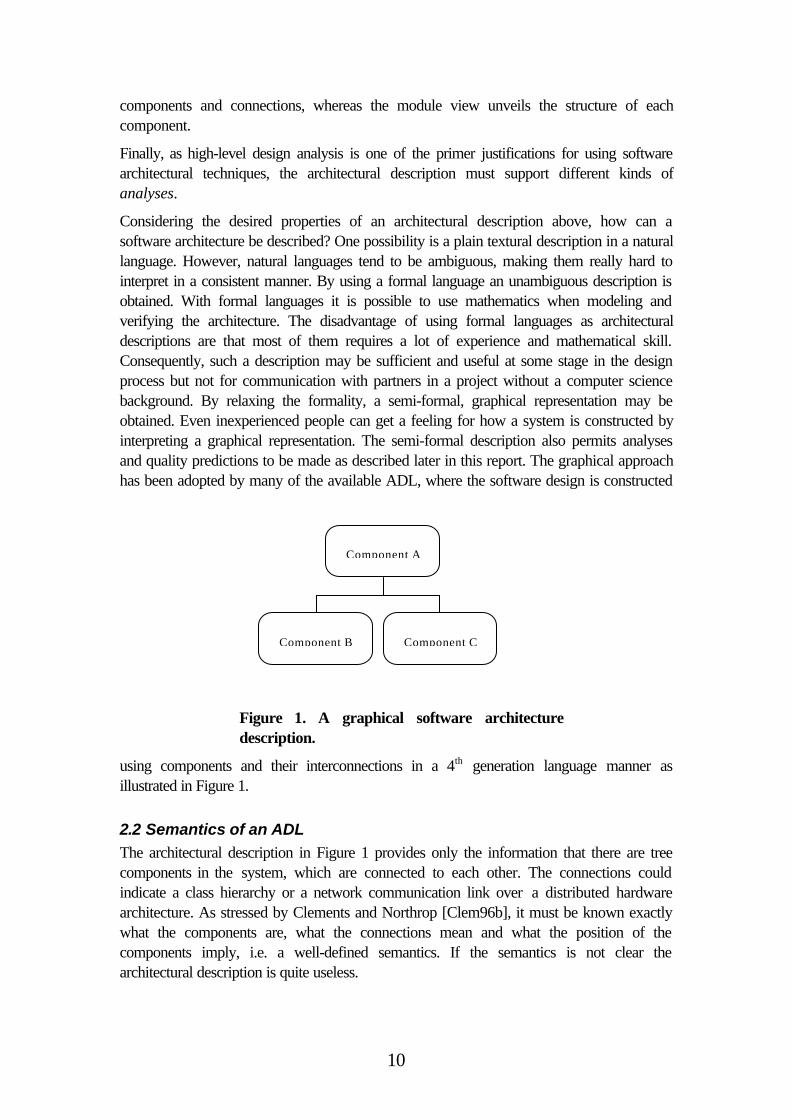
A timed automaton is a finite state machine extended with real-valued clocks that increasesuniformly. Moreover, transitions in a timed automaton are decorated with guards andactions. Guards are clock constraints that enables or disables a transition, i.e. if the guard istrue then the transition can be taken. In Figure 2, the transition from S1 to S2 can be taken ifthe clock x has a value greater than 10 time units.
S2
x>10
S1
Figure 2. A simple timed automaton
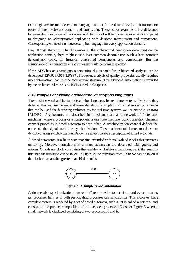
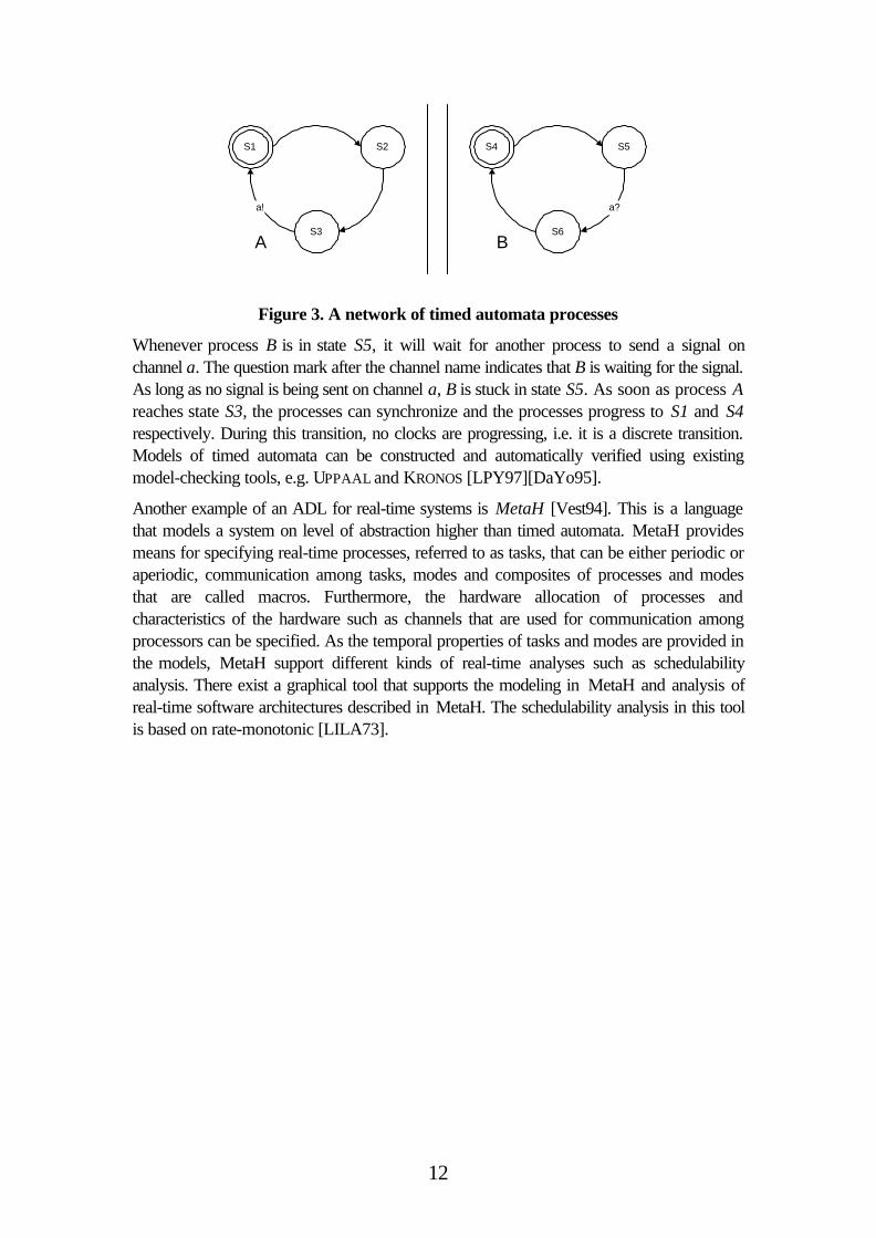
Actions enable synchronization between different timed automata in a rendezvous manner,i.e. processes halts until both participating processes can synchronize. This indicates that acomplete system is modeled by a set of timed automata, such a set is called a network andconsists of the parallel composition of the included processes. Consider Figure 3 where asmall network is displayed consisting of two processes, A and B.
12
S1 S2
S3
a!
S4 S5
S6
a?
A B
Figure 3. A network of timed automata processes
Whenever process B is in state S5, it will wait for another process to send a signal onchannel a. The question mark after the channel name indicates that B is waiting for the signal.As long as no signal is being sent on channel a, B is stuck in state S5. As soon as process Areaches state S3, the processes can synchronize and the processes progress to S1 and S4respectively. During this transition, no clocks are progressing, i.e. it is a discrete transition.Models of timed automata can be constructed and automatically verified using existingmodel-checking tools, e.g. UPPAAL and KRONOS [LPY97][DaYo95].
Another example of an ADL for real-time systems is MetaH [Vest94]. This is a languagethat models a system on level of abstraction higher than timed automata. MetaH providesmeans for specifying real-time processes, referred to as tasks, that can be either periodic oraperiodic, communication among tasks, modes and composites of processes and modesthat are called macros. Furthermore, the hardware allocation of processes andcharacteristics of the hardware such as channels that are used for communication amongprocessors can be specified. As the temporal properties of tasks and modes are provided inthe models, MetaH support different kinds of real-time analyses such as schedulabilityanalysis. There exist a graphical tool that supports the modeling in MetaH and analysis ofreal-time software architectures described in MetaH. The schedulability analysis in this toolis based on rate-monotonic [LILA73].
13
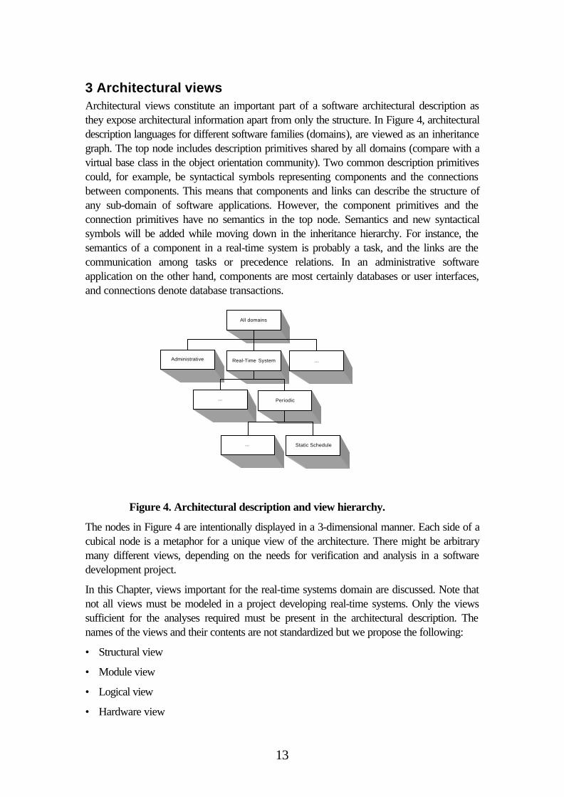
3 Architectural viewsArchitectural views constitute an important part of a software architectural description asthey expose architectural information apart from only the structure. In Figure 4, architecturaldescription languages for different software families (domains), are viewed as an inheritancegraph. The top node includes description primitives shared by all domains (compare with avirtual base class in the object orientation community). Two common description primitivescould, for example, be syntactical symbols representing components and the connectionsbetween components. This means that components and links can describe the structure ofany sub-domain of software applications. However, the component primitives and theconnection primitives have no semantics in the top node. Semantics and new syntacticalsymbols will be added while moving down in the inheritance hierarchy. For instance, thesemantics of a component in a real-time system is probably a task, and the links are thecommunication among tasks or precedence relations. In an administrative softwareapplication on the other hand, components are most certainly databases or user interfaces,and connections denote database transactions.
The nodes in Figure 4 are intentionally displayed in a 3-dimensional manner. Each side of acubical node is a metaphor for a unique view of the architecture. There might be arbitrarymany different views, depending on the needs for verification and analysis in a softwaredevelopment project.
In this Chapter, views important for the real-time systems domain are discussed. Note thatnot all views must be modeled in a project developing real-time systems. Only the viewssufficient for the analyses required must be present in the architectural description. Thenames of the views and their contents are not standardized but we propose the following:
• Structural view
• Module view
• Logical view
• Hardware view
All domains
Administrative Real-Time System ...
... Periodic
... Static Schedule
Figure 4. Architectural description and view hierarchy.
14
• Temporal view
• Communication view
• Synchronization view
Structural view
The structural view describes the overall architectural design and style, providing the highestlevel of abstraction. This is the natural starting point for an architect designing a softwaresystem. The structural view consists of software modules and their interconnections, i.e. theinterfaces between them. The syntactical representation of modules and connections isoptional but should be uniform within the development project for the sake ofcommunication among engineers.
As design on this level is rather rapid, it is possible to design several competing architecturesfor evaluation and comparison. Once a software architecture satisfying the qualityrequirements is selected, it is settled. Depending on the required analyses, more views mighthave to be modeled in order to make a correct decision. For instance one or more of theviews proposed in this chapter could be considered.
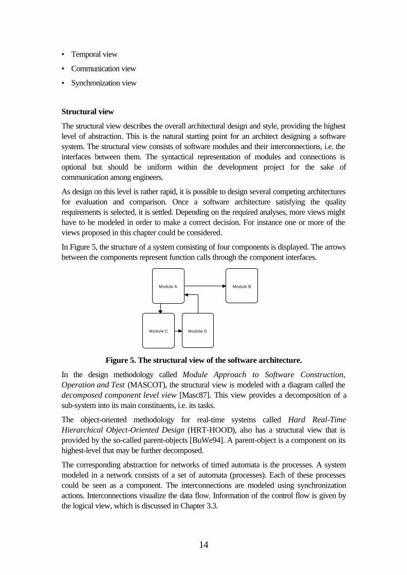
In Figure 5, the structure of a system consisting of four components is displayed. The arrowsbetween the components represent function calls through the component interfaces.
Module A
Module DModule C
Module B
Figure 5. The structural view of the software architecture.
In the design methodology called Module Approach to Software Construction,Operation and Test (MASCOT), the structural view is modeled with a diagram called thedecomposed component level view [Masc87]. This view provides a decomposition of asub-system into its main constituents, i.e. its tasks.
The object-oriented methodology for real-time systems called Hard Real-TimeHierarchical Object-Oriented Design (HRT-HOOD), also has a structural view that isprovided by the so-called parent-objects [BuWe94]. A parent-object is a component on itshighest-level that may be further decomposed.
The corresponding abstraction for networks of timed automata is the processes. A systemmodeled in a network consists of a set of automata (processes). Each of these processescould be seen as a component. The interconnections are modeled using synchronizationactions. Interconnections visualize the data flow. Information of the control flow is given bythe logical view, which is discussed in Chapter 3.3.
15
Module view
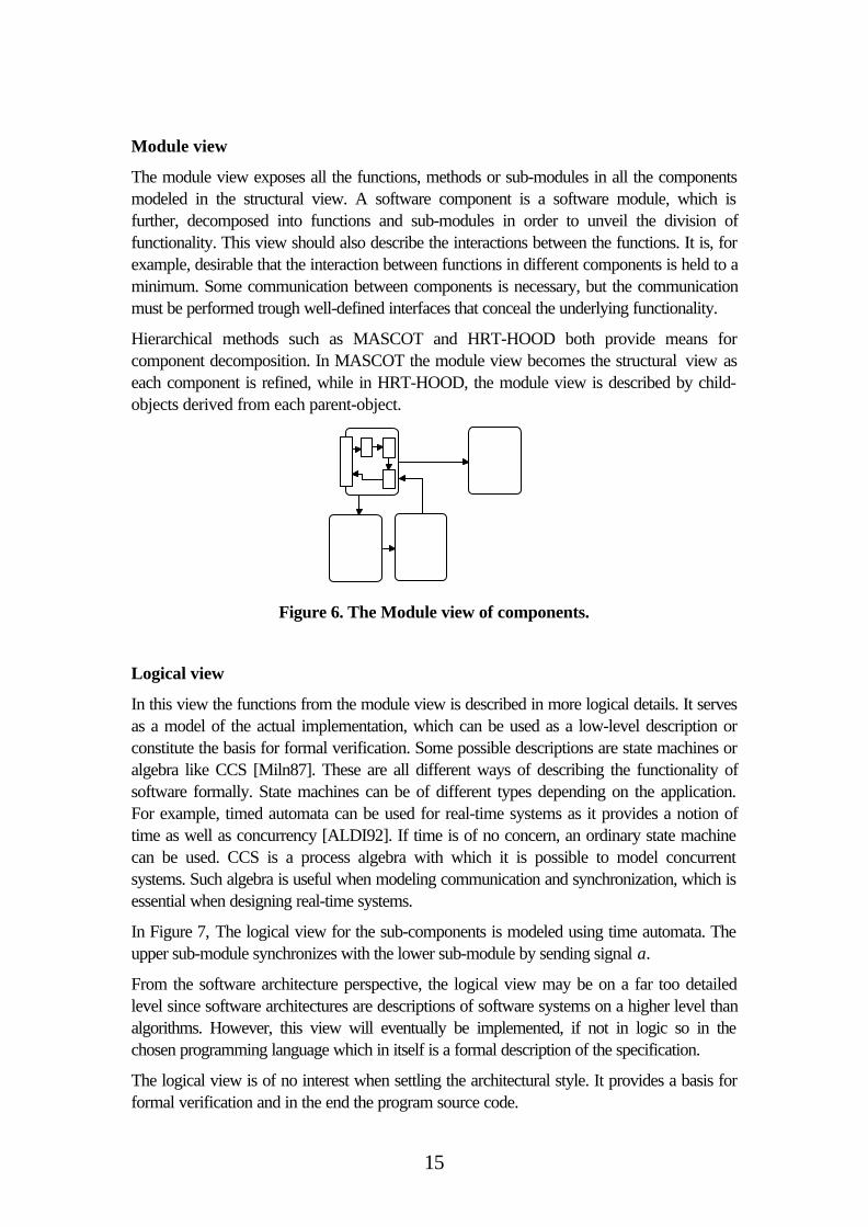
The module view exposes all the functions, methods or sub-modules in all the componentsmodeled in the structural view. A software component is a software module, which isfurther, decomposed into functions and sub-modules in order to unveil the division offunctionality. This view should also describe the interactions between the functions. It is, forexample, desirable that the interaction between functions in different components is held to aminimum. Some communication between components is necessary, but the communicationmust be performed trough well-defined interfaces that conceal the underlying functionality.
Hierarchical methods such as MASCOT and HRT-HOOD both provide means forcomponent decomposition. In MASCOT the module view becomes the structural view aseach component is refined, while in HRT-HOOD, the module view is described by child-objects derived from each parent-object.
Figure 6. The Module view of components.
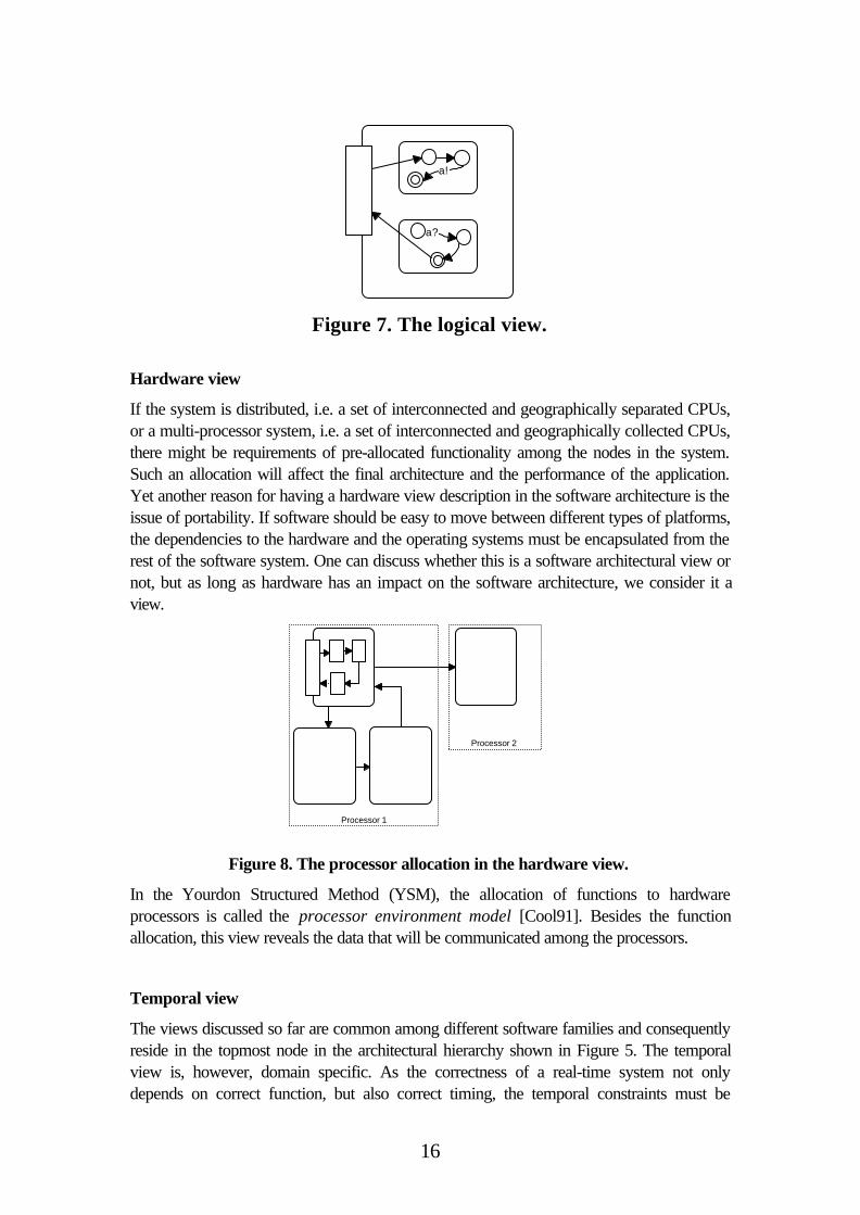
Logical view
In this view the functions from the module view is described in more logical details. It servesas a model of the actual implementation, which can be used as a low-level description orconstitute the basis for formal verification. Some possible descriptions are state machines oralgebra like CCS [Miln87]. These are all different ways of describing the functionality ofsoftware formally. State machines can be of different types depending on the application.For example, timed automata can be used for real-time systems as it provides a notion oftime as well as concurrency [ALDI92]. If time is of no concern, an ordinary state machinecan be used. CCS is a process algebra with which it is possible to model concurrentsystems. Such algebra is useful when modeling communication and synchronization, which isessential when designing real-time systems.
In Figure 7, The logical view for the sub-components is modeled using time automata. Theupper sub-module synchronizes with the lower sub-module by sending signal a.
From the software architecture perspective, the logical view may be on a far too detailedlevel since software architectures are descriptions of software systems on a higher level thanalgorithms. However, this view will eventually be implemented, if not in logic so in thechosen programming language which in itself is a formal description of the specification.
The logical view is of no interest when settling the architectural style. It provides a basis forformal verification and in the end the program source code.
16
a!
a?
Figure 7. The logical view.
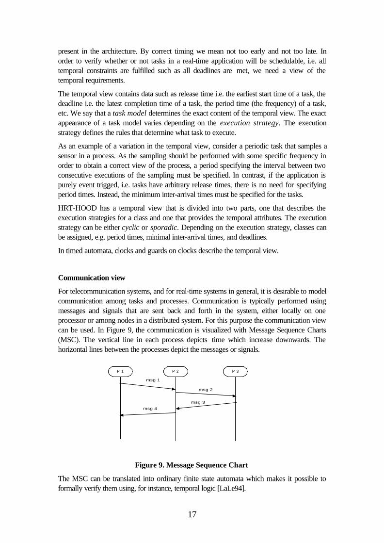
Hardware view
If the system is distributed, i.e. a set of interconnected and geographically separated CPUs,or a multi-processor system, i.e. a set of interconnected and geographically collected CPUs,there might be requirements of pre-allocated functionality among the nodes in the system.Such an allocation will affect the final architecture and the performance of the application.Yet another reason for having a hardware view description in the software architecture is theissue of portability. If software should be easy to move between different types of platforms,the dependencies to the hardware and the operating systems must be encapsulated from therest of the software system. One can discuss whether this is a software architectural view ornot, but as long as hardware has an impact on the software architecture, we consider it aview.
Processor 1
Processor 2
Figure 8. The processor allocation in the hardware view.
In the Yourdon Structured Method (YSM), the allocation of functions to hardwareprocessors is called the processor environment model [Cool91]. Besides the functionallocation, this view reveals the data that will be communicated among the processors.
Temporal view
The views discussed so far are common among different software families and consequentlyreside in the topmost node in the architectural hierarchy shown in Figure 5. The temporalview is, however, domain specific. As the correctness of a real-time system not onlydepends on correct function, but also correct timing, the temporal constraints must be
17
present in the architecture. By correct timing we mean not too early and not too late. Inorder to verify whether or not tasks in a real-time application will be schedulable, i.e. alltemporal constraints are fulfilled such as all deadlines are met, we need a view of thetemporal requirements.
The temporal view contains data such as release time i.e. the earliest start time of a task, thedeadline i.e. the latest completion time of a task, the period time (the frequency) of a task,etc. We say that a task model determines the exact content of the temporal view. The exactappearance of a task model varies depending on the execution strategy. The executionstrategy defines the rules that determine what task to execute.
As an example of a variation in the temporal view, consider a periodic task that samples asensor in a process. As the sampling should be performed with some specific frequency inorder to obtain a correct view of the process, a period specifying the interval between twoconsecutive executions of the sampling must be specified. In contrast, if the application ispurely event trigged, i.e. tasks have arbitrary release times, there is no need for specifyingperiod times. Instead, the minimum inter-arrival times must be specified for the tasks.
HRT-HOOD has a temporal view that is divided into two parts, one that describes theexecution strategies for a class and one that provides the temporal attributes. The executionstrategy can be either cyclic or sporadic. Depending on the execution strategy, classes canbe assigned, e.g. period times, minimal inter-arrival times, and deadlines.
In timed automata, clocks and guards on clocks describe the temporal view.
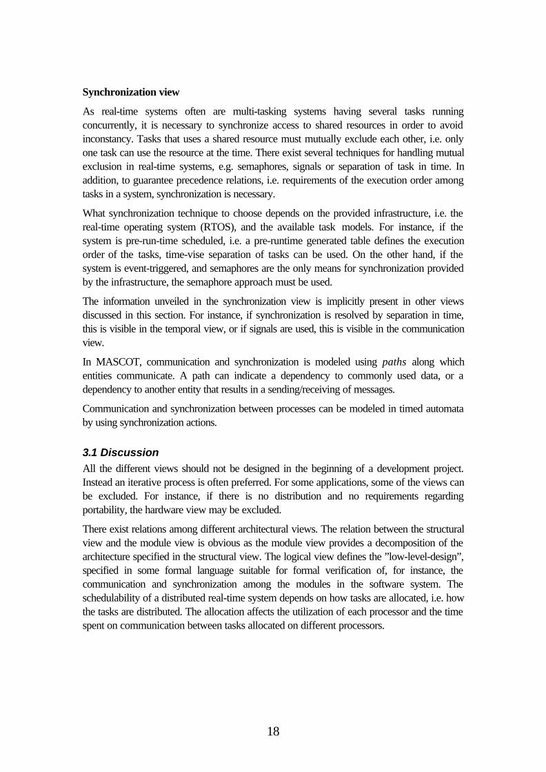
Communication view
For telecommunication systems, and for real-time systems in general, it is desirable to modelcommunication among tasks and processes. Communication is typically performed usingmessages and signals that are sent back and forth in the system, either locally on oneprocessor or among nodes in a distributed system. For this purpose the communication viewcan be used. In Figure 9, the communication is visualized with Message Sequence Charts(MSC). The vertical line in each process depicts time which increase downwards. Thehorizontal lines between the processes depict the messages or signals.
P 1 P 3P 2
msg 1
msg 2
msg 3msg 4
Figure 9. Message Sequence Chart
The MSC can be translated into ordinary finite state automata which makes it possible toformally verify them using, for instance, temporal logic [LaLe94].
18
Synchronization view
As real-time systems often are multi-tasking systems having several tasks runningconcurrently, it is necessary to synchronize access to shared resources in order to avoidinconstancy. Tasks that uses a shared resource must mutually exclude each other, i.e. onlyone task can use the resource at the time. There exist several techniques for handling mutualexclusion in real-time systems, e.g. semaphores, signals or separation of task in time. Inaddition, to guarantee precedence relations, i.e. requirements of the execution order amongtasks in a system, synchronization is necessary.
What synchronization technique to choose depends on the provided infrastructure, i.e. thereal-time operating system (RTOS), and the available task models. For instance, if thesystem is pre-run-time scheduled, i.e. a pre-runtime generated table defines the executionorder of the tasks, time-vise separation of tasks can be used. On the other hand, if thesystem is event-triggered, and semaphores are the only means for synchronization providedby the infrastructure, the semaphore approach must be used.
The information unveiled in the synchronization view is implicitly present in other viewsdiscussed in this section. For instance, if synchronization is resolved by separation in time,this is visible in the temporal view, or if signals are used, this is visible in the communicationview.
In MASCOT, communication and synchronization is modeled using paths along whichentities communicate. A path can indicate a dependency to commonly used data, or adependency to another entity that results in a sending/receiving of messages.
Communication and synchronization between processes can be modeled in timed automataby using synchronization actions.
3.1 Discussion
All the different views should not be designed in the beginning of a development project.Instead an iterative process is often preferred. For some applications, some of the views canbe excluded. For instance, if there is no distribution and no requirements regardingportability, the hardware view may be excluded.
There exist relations among different architectural views. The relation between the structuralview and the module view is obvious as the module view provides a decomposition of thearchitecture specified in the structural view. The logical view defines the ”low-level-design”,specified in some formal language suitable for formal verification of, for instance, thecommunication and synchronization among the modules in the software system. Theschedulability of a distributed real-time system depends on how tasks are allocated, i.e. howthe tasks are distributed. The allocation affects the utilization of each processor and the timespent on communication between tasks allocated on different processors.
19
4 Architectural analysisThe main incitement for using software architecture notation when designing a softwaresystem is the ability to analyze and verify the design in an early stage of the developmentprocess. By comparing different candidate architectures, confidence in early designdecisions is achieved. Such a comparison is done by listing pros and cons for eacharchitectural solution according to the quality requirements put on the system. Furthermore,architectural analysis enables the possibility to get software metrics based on the high-leveldesign, e.g. the level of coupling and cohesion within and between the different modules thatconstitute the software system [Fenton96].
In this report, the software system quality properties are divided into two different classes,functional and nonfunctional. Functional quality properties are those concerned with theruntime behavior of the software, e.g. performance or reliability, whereas nonfunctionalquality properties are concerned with the quality of the software itself, e.g. maintainability orreusability. Most of these software quality properties are qualitative rather than quantitative,thus being practicable only for comparison between different architectures.
4.1 Methods for architectural analysis
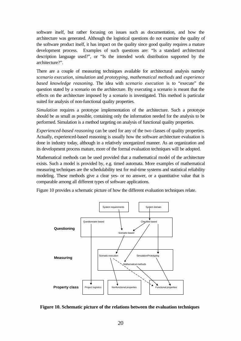
An architectural analysis process is divided into two stages, questioning and measuring.The questioning phase generates questions that are answered by the measuring phase. LenBass et. al. [BCK98], have categorized the questioning stage in architectural review andevaluation into three different classes namely Scenario-based, checklist-based andquestionnaire-based.
Scenarios are a set of cases where the software architect asks a lot of ”what if” questionsthat reflect the requirements. It is however not a trivial task to construct the right questionsand to know when to stop generating scenarios. This requires a lot of experience andknowledge, which can be achieved by being involved in many design projects. A scenario isalways system specific, i.e. tailor-made for a particular application in a domain, whereasquestions that are valid for all architectures in a particular domain resides in a checklist. Theitems in the checklist can either generate scenarios or be verified in the measuring stagedirectly. As an example, consider the domain of safety-critical real-time systems. Thechecklist contains the following items:
1. Is the system schedulable?
2. Is there error recovery code in the system to clean up after error detection?
The first item is verified directly by performing a mathematical schedulability analysis. Thesecond item is too general and therefore it must be formalized into a set of scenarios beforeit can be answered. As scenarios are system specific, they can stress different types oferrors in specific modules residing in the system. One possible scenario is: “What happenwhen division by zero occurs in the control task”. The scenarios can than be verified by,for instance, simulation or scenario execution, both described later in this chapter.
The questionnaire-based questioning typically stresses general logistical softwarearchitecture questions. These questions have usually very little to do with the quality of the
20
software itself, but rather focusing on issues such as documentation, and how thearchitecture was generated. Although the logistical questions do not examine the quality ofthe software product itself, it has impact on the quality since good quality requires a maturedevelopment process. Examples of such questions are: “Is a standard architecturaldescription language used?”, or “Is the intended work distribution supported by thearchitecture?”.
There are a couple of measuring techniques available for architectural analysis namelyscenario execution, simulation and prototyping, mathematical methods and experiencebased knowledge reasoning. The idea with scenario execution is to “execute” thequestion stated by a scenario on the architecture. By executing a scenario is meant that theeffects on the architecture imposed by a scenario is investigated. This method is particularsuited for analysis of non-functional quality properties.
Simulation requires a prototype implementation of the architecture. Such a prototypeshould be as small as possible, containing only the information needed for the analysis to beperformed. Simulation is a method targeting on analysis of functional quality properties.
Experienced-based reasoning can be used for any of the two classes of quality properties.Actually, experienced-based reasoning is usually how the software architecture evaluation isdone in industry today, although in a relatively unorganized manner. As an organization andits development process mature, more of the formal evaluation techniques will be adopted.
Mathematical methods can be used provided that a mathematical model of the architectureexists. Such a model is provided by, e.g. timed automata. More examples of mathematicalmeasuring techniques are the schedulability test for real-time systems and statistical reliabilitymodeling. These methods give a clear yes- or no answer, or a quantitative value that iscomparable among all different types of software applications.
Figure 10 provides a schematic picture of how the different evaluation techniques relate.
Questionnaire based Checklist based
Scenario based
Nonfunctional properties Functional properties
Scenario execution Simulation/Prototyping
Mathematical methods
Project logistics
Questioning
Measuring
Property class
System requirements System domain
Figure 10. Schematic picture of the relations between the evaluation techniques
21
Although measuring techniques might give quantitative values, these values must be treatedcarefully. The quantitative values should be used as relative values when comparingcompeting software architectures. Moreover, if scenarios or experienced reasoning wasused to obtain the values, the exact same set of scenarios and reasoning must be used whenevaluating the competing or refined architecture. Otherwise, the measures are notcomparable. Consequently, it is impossible to compare measured quality of a softwarearchitecture across the application domain i.e. within the same class of products but indifferent environments or applications.
4.2 Functional analysis
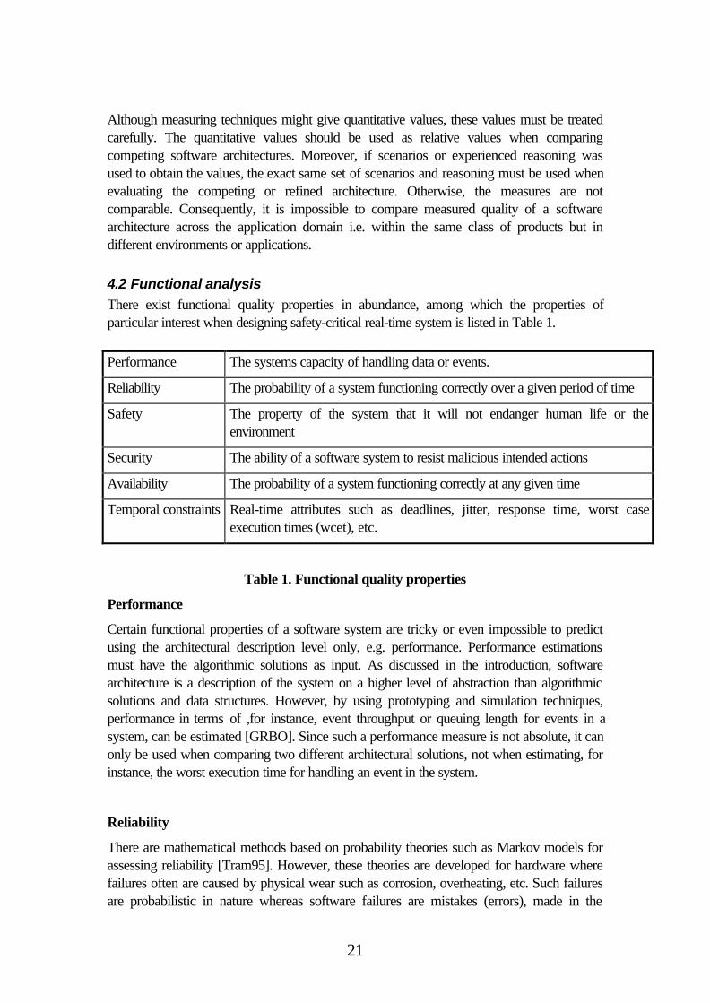
There exist functional quality properties in abundance, among which the properties ofparticular interest when designing safety-critical real-time system is listed in Table 1.
Performance The systems capacity of handling data or events.
Reliability The probability of a system functioning correctly over a given period of time
Safety The property of the system that it will not endanger human life or theenvironment
Security The ability of a software system to resist malicious intended actions
Availability The probability of a system functioning correctly at any given time
Temporal constraints Real-time attributes such as deadlines, jitter, response time, worst caseexecution times (wcet), etc.
Table 1. Functional quality properties
Performance
Certain functional properties of a software system are tricky or even impossible to predictusing the architectural description level only, e.g. performance. Performance estimationsmust have the algorithmic solutions as input. As discussed in the introduction, softwarearchitecture is a description of the system on a higher level of abstraction than algorithmicsolutions and data structures. However, by using prototyping and simulation techniques,performance in terms of ,for instance, event throughput or queuing length for events in asystem, can be estimated [GRBO]. Since such a performance measure is not absolute, it canonly be used when comparing two different architectural solutions, not when estimating, forinstance, the worst execution time for handling an event in the system.
Reliability
There are mathematical methods based on probability theories such as Markov models forassessing reliability [Tram95]. However, these theories are developed for hardware wherefailures often are caused by physical wear such as corrosion, overheating, etc. Such failuresare probabilistic in nature whereas software failures are mistakes (errors), made in the
22
specification, the design or in the implementation. These types of failures are certainly notprobabilistic according to some distribution over time. Furthermore, software can never beworn out. Attempts have been made to apply the methods from the hardware community tosoftware. In software, the statistics are the numbers of errors in the program or thelikelihood of a failure in a point of time based upon the error distribution in the past[Fenton96]. To get such failure estimations, there must be an implementation of theapplication or at least a prototype. Anyhow, a description of the application on a lower levelthan the architecture is needed. With some heuristics from similar applications developedearlier experienced engineers can estimate the expected number of errors in thecomponents. Such estimations are very complex, giving rough metrics. An alternative todirectly measure the reliability of the architecture is to measure the testability. The testabilityis a function of the effort required in order to assure the required level of reliability oravailability.
There are three different approaches to handle faults in order to achieve a reliable system[Lapr92]:
• Fault avoidance
• Fault removal
• Fault tolerance
Fault avoidance is about designing error free systems. This implies the use of structureddesign methodologies such as formal methods or semi-formal methods. Formal methods arebased on mathematical models of the software system and the requirement specification.These models form the basis when proving correctness of the model with respect to thesystem specification. There exists a wide area of formal methods and formal modelinglanguages, each supporting different system domains. Semi-formal methods are, as the namesuggests, less formal, i.e. they do not support techniques to exhaustively prove correctnessof the models. Instead, they offer a structured way of reasoning, both when designingmodels of the system and when analyzing the models. The methods are usually based onsome “formal” notation, e.g. Unified Modeling Language (UML)[BRJ98], ADLs, etc.,representing the system model. Examples of such methods are object-oriented analysisand design (OOA/OOD), and software architecture techniques in general.
No matter how accurate the models are analyzed, there may still be errors in theimplementation. These errors usually originate from the specification and from the mismatchwhen mapping the models to the source code. In order to improve reliability in the program,fault removal techniques can be applied. Fault removal is basically the task of finding theerrors by testing and removal of them by error correction. Under the assumption that nonew errors are introduced, the reliability will grow as errors are corrected. This assumptionis, unfortunately, seldom true, implying that the whole system has to be re-tested after eachincrement. The results from testing and re-testing can be used for statistically forecasting ofthe failure rate (and consequently the reliability), of a software system. Such a method is thereliability growth model, first proposed for software by Jelinsky et. al. [JEMO72]. Thereexist an abundance of different approaches to model reliability growth; they are all based ondata collected during testing, but differ in the way the statistical model is made.
23
Some faults are impossible to avoid regardless of how accurate the design and the tests areperformed. If it is particularly important that a certain module in the system does not fail,fault-tolerance can be introduced. Fault-tolerance is a technique which can be interpretedin two different ways: it could be the ability of a software system to tolerate faults from itsenvironment, e.g. the operator, hardware errors, etc., or it could mean that the systemshould be tolerant against design faults in the software itself. The two different fault-toleranceapproaches are, naturally, solved using different techniques. For instance, to be fault-tolerantagainst hardware errors such as electromagnetic distortion, redundant hardware can beused, each with equivalent software running on them. This solution will however not toleratesoftware faults. Different approaches to be tolerant against software faults are recoveryblocks and N-version programming [Storey96][CA78].
Recovery blocks are based on acceptant tests of the calculated values. If the processedvalue is not accepted the program tracks back to a recovery point where it is safe tocontinue the execution after having restored the system’s state.
N-version programming is achieved by developing N different versions of the software;each developed by different and isolated design teams. All N different versions run in parallelat runtime and their respective results are voted upon. This technique has, however, beenproven not so successful since all different versions of the software start out from the samespecification, and since most design errors originate from the specification, they will containcommon errors.
Even if the source code is absolutely correct, the compiler may still produce erroneousbinaries. Faults introduced by the compiler can be tolerated by using the N-versionapproach. Each version has exactly the same code, but they are all compiled using differentcompilers.
It is important to note that the different techniques discussed above can be applied at anystage in the development process. For instance fault removal can be used when verifying thedesigned architecture against the system specification. Fault-tolerance is also a matter ofarchitectural design. The techniques for fault-tolerance discussed above are all achievedusing different architectural solutions.
Safety
Safety seems, at a first glance, very similar to reliability. There is however a clear distinctionas safety is only concerned with failures that endangers human life and the environment, i.e.hazards, whereas reliability deals with all failures regardless of their consequences.However, before any safety analysis of the architecture can be performed, the hazards mustbe identified. This is done in a hazard analysis that is a reasoning based method for findingall hazards in the system that is going to be designed [Leve95].
There exist several techniques for assessing safety properties in software designs. Most ofthem are scenario based and work either backward or forward. If the method worksbackwards, the analysis starts with the hazard as a scenario, trying to trace down theresponsible component. On the contrary, if the method works forward, the effects of anerror in a component is investigated.
24
Some of the most well known forward methods are Failure Mode and Effects Analysis(FMEA) and Hazard and Operability studies (HAZOP). Both methods analyze theconsequences of failures in the components. One commonly used backward technique iscalled Fault Tree Analysis (FTA)[Storey96]. FTA starts with a hazard, trying to determineits origin among the components. This kind of analyses give an understanding of where in thearchitecture fault-tolerance techniques should be introduced, or if already introduced,verifying whether the intended fault-tolerance is achieved or not.
Depending on the results from the safety analysis, changes in the design may have to beperformed. Different design approaches to avoid catastrophic failures can be applied basedon the severity of an accident caused by the hazard. The different approaches are [Leve95]:
• Hazard elimination
• Hazard reduction
• Hazard control
• Damage minimization
The severity is a quantified value that makes it possible to compare and rank hazards.Typically, the severity is given in terms of the cost or, lost lives, for the stakeholder if theaccident occurs.
Substitution, decoupling, and simplifications achieve hazard elimination. By substitute adangerous design possibility by a functionally equivalent, but not dangerous solution, thehazard itself is eliminated. For instance, if the system involves a very toxic chemical liquid,substituting the liquid with a non-toxic one eliminates the hazard. Moreover, by decouplingsafety-critical parts of the software from non-critical software, the risk for an error in thenon-critical part to propagate into the safety-critical parts is eliminated. There exist someknown architectural solutions based on decoupling, e.g. safety kernels, firewalls, hierarchicalarchitectures [Storey96].
Hazard reduction reduces the likelihood of the occurrence of a hazard. It might not befeasible or even possible, to eliminate the hazards. Then the designer has to design thesystem in such a way that the hazard is not very likely to occur. An example of hazardreduction is to erect a fence around an industrial robot, preventing humans to come closeenough in order to get hurt.
Hazard control is applied in order to reduce the likelihood of an accident if a hazard arises.This can be achieved using fail-safe design, i.e. the system should be designed to detect thehazard and then transfer it into a safe state if such exists. There are, however systems whereno safe state exists. A typically example of such a system is airplanes. These systems mustkeep operating even if something goes wrong. This is achieved using fault-tolerance such asredundancy. It is essential that an airplane keeps flying even if one engine breaks down byusing the second engine. The performance will of course be reduced, but the airplane canstill be maneuvered to its safe state on the ground.
Yet, if an accident still occurs, the consequences and losses must be reduced. This isachieved with damage minimization that strives to minimize the exposure of the accident tothe environment or human beings.
25
Availability
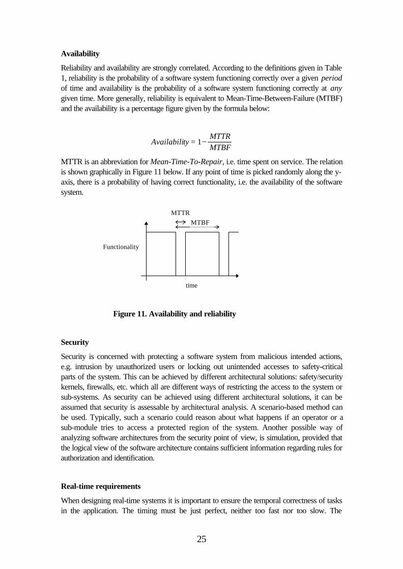
Reliability and availability are strongly correlated. According to the definitions given in Table1, reliability is the probability of a software system functioning correctly over a given periodof time and availability is the probability of a software system functioning correctly at anygiven time. More generally, reliability is equivalent to Mean-Time-Between-Failure (MTBF)and the availability is a percentage figure given by the formula below:
AvailabilityMTTRMTBF
= −1
MTTR is an abbreviation for Mean-Time-To-Repair, i.e. time spent on service. The relationis shown graphically in Figure 11 below. If any point of time is picked randomly along the y-axis, there is a probability of having correct functionality, i.e. the availability of the softwaresystem.
Security
Security is concerned with protecting a software system from malicious intended actions,e.g. intrusion by unauthorized users or locking out unintended accesses to safety-criticalparts of the system. This can be achieved by different architectural solutions: safety/securitykernels, firewalls, etc. which all are different ways of restricting the access to the system orsub-systems. As security can be achieved using different architectural solutions, it can beassumed that security is assessable by architectural analysis. A scenario-based method canbe used. Typically, such a scenario could reason about what happens if an operator or asub-module tries to access a protected region of the system. Another possible way ofanalyzing software architectures from the security point of view, is simulation, provided thatthe logical view of the software architecture contains sufficient information regarding rules forauthorization and identification.
Real-time requirements
When designing real-time systems it is important to ensure the temporal correctness of tasksin the application. The timing must be just perfect, neither too fast nor too slow. The
time
Functionality
MTBF
MTTR
Figure 11. Availability and reliability
26
information necessary for the verification of temporal constraints is provided by the temporalview of the architecture. A typical example of such an analysis are schedulability test, i.e.analyzing whether the task set is schedulable or not given the resources and temporalconstraints given as release times, deadlines, worst case execution times (wcet), jitter, etc.The resources taken into account when analyzing the schedulability of a system are typicallyCPUs, communication busses, actuators, etc.
There exist a lot of mathematical methods for verifying the temporal behavior of a real-timesystem, all having different assumptions on the scheduling strategy and the task model[LILA73][ABDTW95]. A task model defines the temporal requirements put upon a task,i.e. priorities, period times, etc. The task model and the scheduling strategy is stronglycoupled since the task model provide the input to the schedulability analysis.
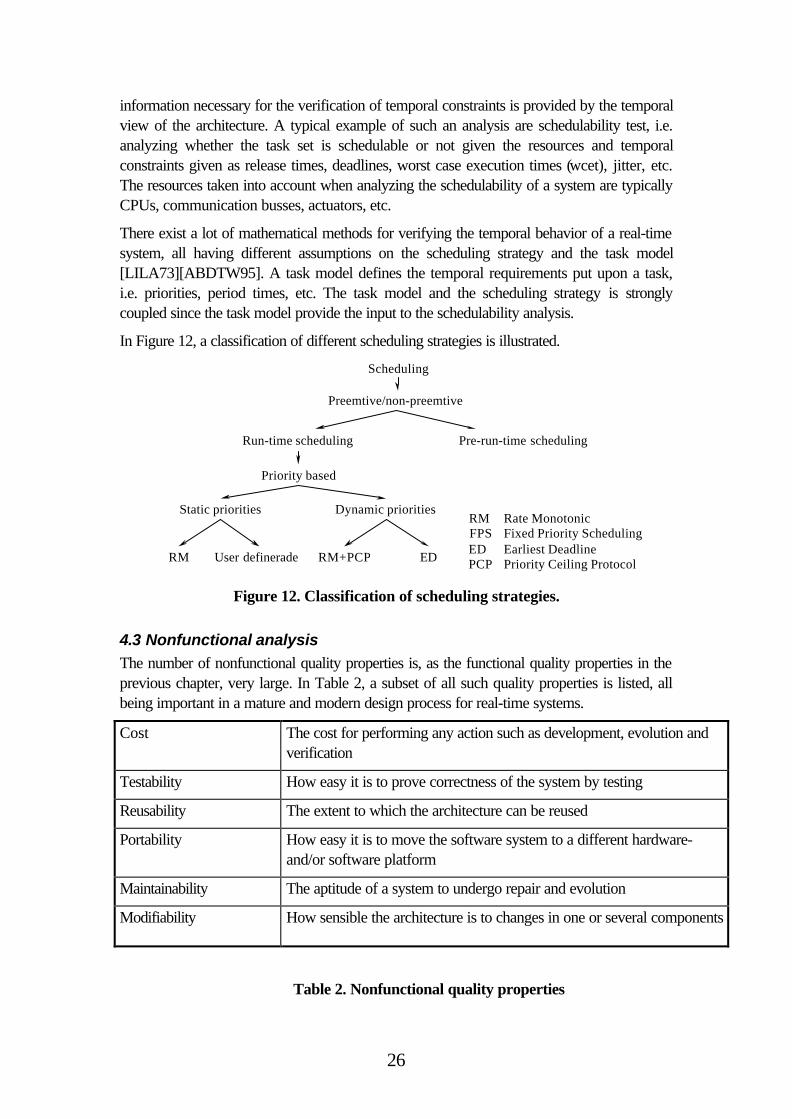
In Figure 12, a classification of different scheduling strategies is illustrated.
Run-time scheduling
Priority based
Static priorities Dynamic priorities
User defineradeRM RM+PCP ED
RM Rate Monotonic FPS Fixed Priority Scheduling ED Earliest Deadline PCP Priority Ceiling Protocol
Pre-run-time scheduling
Preemtive/non-preemtive
Scheduling
Figure 12. Classification of scheduling strategies.
4.3 Nonfunctional analysis
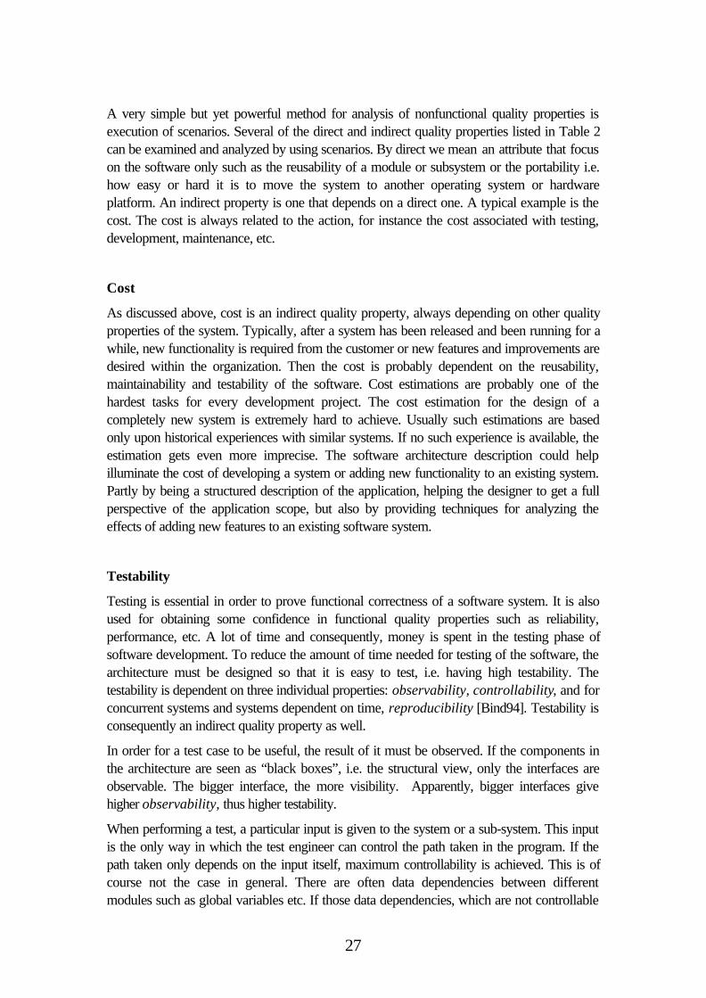
The number of nonfunctional quality properties is, as the functional quality properties in theprevious chapter, very large. In Table 2, a subset of all such quality properties is listed, allbeing important in a mature and modern design process for real-time systems.
Cost The cost for performing any action such as development, evolution andverification
Testability How easy it is to prove correctness of the system by testing
Reusability The extent to which the architecture can be reused
Portability How easy it is to move the software system to a different hardware-and/or software platform
Maintainability The aptitude of a system to undergo repair and evolution
Modifiability How sensible the architecture is to changes in one or several components
Table 2. Nonfunctional quality properties
27
A very simple but yet powerful method for analysis of nonfunctional quality properties isexecution of scenarios. Several of the direct and indirect quality properties listed in Table 2can be examined and analyzed by using scenarios. By direct we mean an attribute that focuson the software only such as the reusability of a module or subsystem or the portability i.e.how easy or hard it is to move the system to another operating system or hardwareplatform. An indirect property is one that depends on a direct one. A typical example is thecost. The cost is always related to the action, for instance the cost associated with testing,development, maintenance, etc.
Cost
As discussed above, cost is an indirect quality property, always depending on other qualityproperties of the system. Typically, after a system has been released and been running for awhile, new functionality is required from the customer or new features and improvements aredesired within the organization. Then the cost is probably dependent on the reusability,maintainability and testability of the software. Cost estimations are probably one of thehardest tasks for every development project. The cost estimation for the design of acompletely new system is extremely hard to achieve. Usually such estimations are basedonly upon historical experiences with similar systems. If no such experience is available, theestimation gets even more imprecise. The software architecture description could helpilluminate the cost of developing a system or adding new functionality to an existing system.Partly by being a structured description of the application, helping the designer to get a fullperspective of the application scope, but also by providing techniques for analyzing theeffects of adding new features to an existing software system.
Testability
Testing is essential in order to prove functional correctness of a software system. It is alsoused for obtaining some confidence in functional quality properties such as reliability,performance, etc. A lot of time and consequently, money is spent in the testing phase ofsoftware development. To reduce the amount of time needed for testing of the software, thearchitecture must be designed so that it is easy to test, i.e. having high testability. Thetestability is dependent on three individual properties: observability, controllability, and forconcurrent systems and systems dependent on time, reproducibility [Bind94]. Testability isconsequently an indirect quality property as well.
In order for a test case to be useful, the result of it must be observed. If the components inthe architecture are seen as “black boxes”, i.e. the structural view, only the interfaces areobservable. The bigger interface, the more visibility. Apparently, bigger interfaces givehigher observability, thus higher testability.
When performing a test, a particular input is given to the system or a sub-system. This inputis the only way in which the test engineer can control the path taken in the program. If thepath taken only depends on the input itself, maximum controllability is achieved. This is ofcourse not the case in general. There are often data dependencies between differentmodules such as global variables etc. If those data dependencies, which are not controllable
28
by the test input data, affect the control flow, the controllability is decreased, giving lowertestability.
Finally, when testing concurrent system or real-time systems in general, the order in whichdifferent processes in the system are executed will influence the observed result from a test.For instance, in a system controlling the water level in a tank, there is one process samplingthe actual water level and one process calculating how to adjust the water level based on themeasured value and some set value. If the control process executes twice without anyintermediate execution of the sampling process, the result of the control decision will bedifferent in the second invocation than if the water level was re-sampled in between. To gethigh testability, the order in which processes execute must be controllable or deterministic,i.e. high reproducibility [ThHa99].
Reusability
Reusing a software component to its full extent, without any modifications, is extremelydifficult if not the domain in which the reuse is intended is the exact domain of the componentorigin. When a component or architecture is reused in the same application domain we call ita domain-dependent reuse. When containers are reused, i.e. lists, arrays, sets, etc., they canbe reused across different application domains. An example of such reuse is the StandardTemplate Library (STL) for the object-oriented language C++. Reuse, which is possibleacross the application domains, is consequently called domain-independent reuse.
When analyzing the level of reusability of a component or a part of the architecture, onemust consider not only the original application domain, but also how isolated andindependent it is from rest of the system. The less dependencies, the more reusable, and viceversa.
The focus on reuse, in industry, has been intensified due to the potential cuts of cost. Thetime spent on implementation decreases when reusing components. Furthermore,components can be bought from third-party developers. Such components are calledCommercial-Off-The-Shelf components (COTS).
Portability
To be able to analyze software architectures with respect to portability, the platform onwhich the system is going to run on has to be modeled as well. This to unveil thedependencies between the software components in the system and the platform. Asplatform we consider the hardware, e.g. processors, A/D converters, as well as thesoftware providing the infrastructure e.g. operating systems. If the amount of directdependencies, i.e. the number of components having a direct connection to the platform, islow, then the architecture as whole is quite insensible to a change of platform. Thus, having ahigh degree of portability.
Maintainability
29
Kazman et. al. [KAC96], have proposed a methodology for visualizing the amount ofchanges required in the modules or in the architecture when adding or changing functionalityin the system. The amount of changes in the software architecture enforced by adding newfunctionality or error corrections, are referred to as maintainability. By using scenariosdeveloped from the requirements of the new function, the existing architecture is analyzed.
The concept, direct scenarios, were introduced meaning scenarios that are directlysupported by the existing architecture i.e. no major architectural changes are required. Inopposite, an indirect scenario exposes the need for architectural changes, which is moredifficult and costly to achieve. Remember that there is a difference between a direct orindirect scenario and the direct and indirect quality properties introduced earlier in thischapter. After having mapped the scenarios on the architectural structure and determined ifthe scenario is direct or indirect, scenario interaction should be revealed. Two or moreindirect scenarios are said to interact if they affect the same module.
To make the potential architectural violations and changes in the system visible, graphicalrepresentation of modules were scaled in the ADL according to the amount of indirectscenario interactions.

30
31
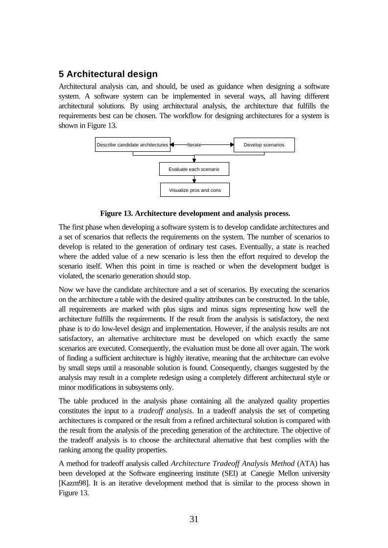
5 Architectural designArchitectural analysis can, and should, be used as guidance when designing a softwaresystem. A software system can be implemented in several ways, all having differentarchitectural solutions. By using architectural analysis, the architecture that fulfills therequirements best can be chosen. The workflow for designing architectures for a system isshown in Figure 13.
The first phase when developing a software system is to develop candidate architectures anda set of scenarios that reflects the requirements on the system. The number of scenarios todevelop is related to the generation of ordinary test cases. Eventually, a state is reachedwhere the added value of a new scenario is less then the effort required to develop thescenario itself. When this point in time is reached or when the development budget isviolated, the scenario generation should stop.
Now we have the candidate architecture and a set of scenarios. By executing the scenarioson the architecture a table with the desired quality attributes can be constructed. In the table,all requirements are marked with plus signs and minus signs representing how well thearchitecture fulfills the requirements. If the result from the analysis is satisfactory, the nextphase is to do low-level design and implementation. However, if the analysis results are notsatisfactory, an alternative architecture must be developed on which exactly the samescenarios are executed. Consequently, the evaluation must be done all over again. The workof finding a sufficient architecture is highly iterative, meaning that the architecture can evolveby small steps until a reasonable solution is found. Consequently, changes suggested by theanalysis may result in a complete redesign using a completely different architectural style orminor modifications in subsystems only.
The table produced in the analysis phase containing all the analyzed quality propertiesconstitutes the input to a tradeoff analysis. In a tradeoff analysis the set of competingarchitectures is compared or the result from a refined architectural solution is compared withthe result from the analysis of the preceding generation of the architecture. The objective ofthe tradeoff analysis is to choose the architectural alternative that best complies with theranking among the quality properties.
A method for tradeoff analysis called Architecture Tradeoff Analysis Method (ATA) hasbeen developed at the Software engineering institute (SEI) at Canegie Mellon university[Kazm98]. It is an iterative development method that is similar to the process shown inFigure 13.
Describe candidate architectures Develop scenarios
Evaluate each scenario
Visualize pros and cons
Iterate
Figure 13. Architecture development and analysis process.
32
A method called Software Architecture Analysis Method (SAAM) is also developed atSEI. The purpose of SAAM is to analyze software quality attributes by examiningcompeting architectures [KBAW94]. To do so, they partitioning the functionality in thearchitecture i.e. identifies were in the different architectures the functionality of the system isallocated. The functional partitioning is system domain specific. Some domains already havea well-defined functional partitioning; a typical example of such a domain is compilers.Compilers are built with a front-end, a parser, a code generator etc. However, nothing isassumed about how functions are organized and structured, i.e. the architecture of thecompiler. This partitioning gives a common description and common modules, each with thesame functionality but organized in different ways. The communal description is an absolutecondition for the comparison, which aims to unveil how well a certain quality attribute, isadopted by the architecture. Again, the analysis is based on scenarios, constructing input fora tradeoff analysis.
5.1 An example
As an example of how an architecture is constructed, analyzed and transformed in order tobetter comply with the requirements consider a real-time system that controls the waterlevel in a tank. The system samples a water level sensor, takes a decision whether to letwater out, or pour water into the tank. The system actuates a pump or a valve if the levelhas to be adjusted. As it is a real-time system, the temporal constraints on the system mustbe fulfilled, i.e. there is a functional quality requirement on timing. Moreover, the systemshould easily be modified to run on different platforms (real-time operating system andhardware), i.e. portability.
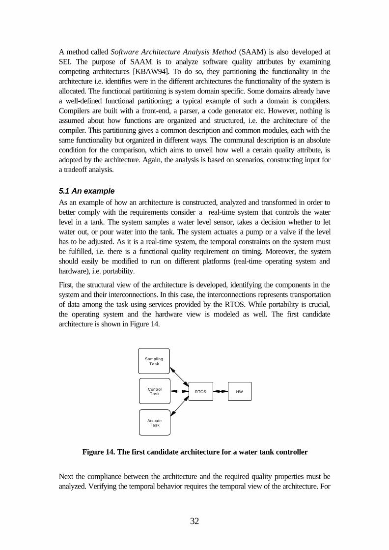
First, the structural view of the architecture is developed, identifying the components in thesystem and their interconnections. In this case, the interconnections represents transportationof data among the task using services provided by the RTOS. While portability is crucial,the operating system and the hardware view is modeled as well. The first candidatearchitecture is shown in Figure 14.
SamplingTask
ControlTask
ActuateTask
RTOS HW
Figure 14. The first candidate architecture for a water tank controller
Next the compliance between the architecture and the required quality properties must beanalyzed. Verifying the temporal behavior requires the temporal view of the architecture. For
33
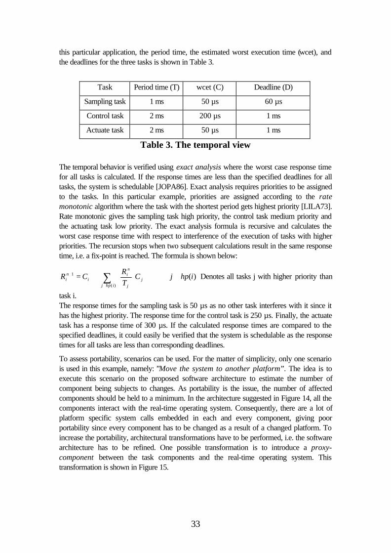
this particular application, the period time, the estimated worst execution time (wcet), andthe deadlines for the three tasks is shown in Table 3.
Task Period time (T) wcet (C) Deadline (D)
Sampling task 1 ms 50 µs 60 µs
Control task 2 ms 200 µs 1 ms
Actuate task 2 ms 50 µs 1 ms
Table 3. The temporal view
The temporal behavior is verified using exact analysis where the worst case response timefor all tasks is calculated. If the response times are less than the specified deadlines for alltasks, the system is schedulable [JOPA86]. Exact analysis requires priorities to be assignedto the tasks. In this particular example, priorities are assigned according to the ratemonotonic algorithm where the task with the shortest period gets highest priority [LILA73].Rate monotonic gives the sampling task high priority, the control task medium priority andthe actuating task low priority. The exact analysis formula is recursive and calculates theworst case response time with respect to interference of the execution of tasks with higherpriorities. The recursion stops when two subsequent calculations result in the same responsetime, i.e. a fix-point is reached. The formula is shown below:
∑∈∀
+
+=
)(
1
ihpjj
j
ni
ini C
TR
CR ∀ ∈j hp i( ) Denotes all tasks j with higher priority than
task i.The response times for the sampling task is 50 µs as no other task interferes with it since ithas the highest priority. The response time for the control task is 250 µs. Finally, the actuatetask has a response time of 300 µs. If the calculated response times are compared to thespecified deadlines, it could easily be verified that the system is schedulable as the responsetimes for all tasks are less than corresponding deadlines.
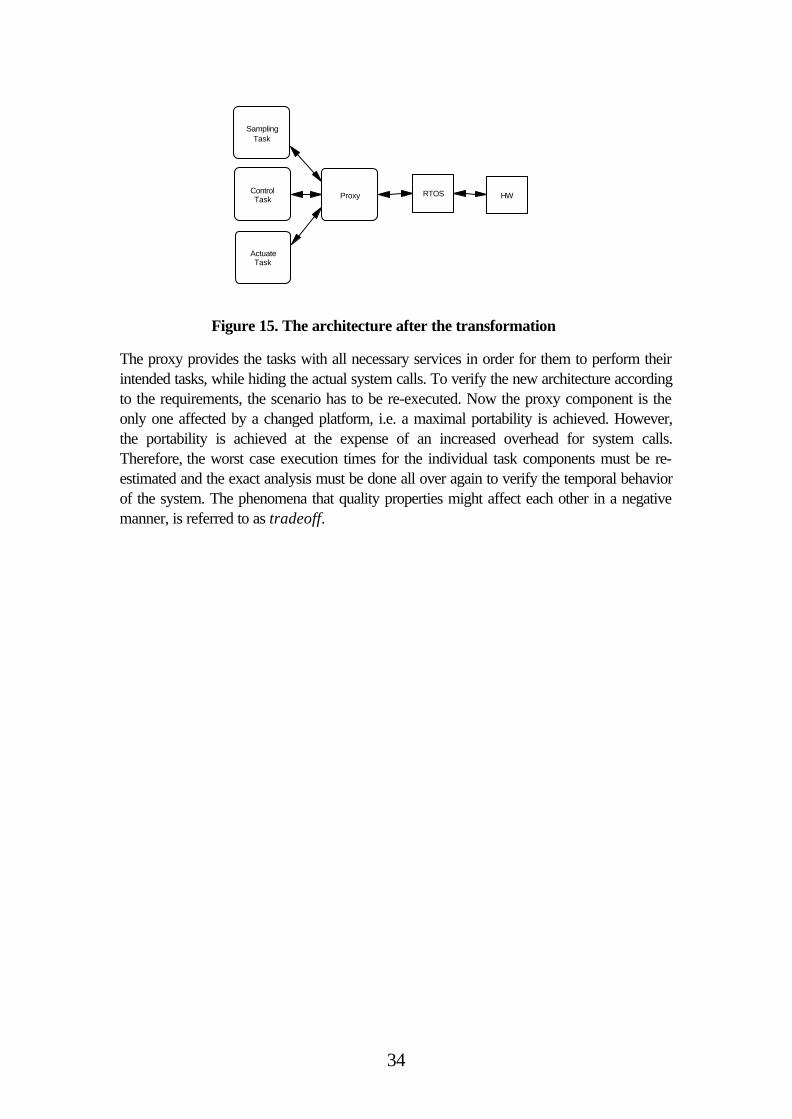
To assess portability, scenarios can be used. For the matter of simplicity, only one scenariois used in this example, namely: ”Move the system to another platform”. The idea is toexecute this scenario on the proposed software architecture to estimate the number ofcomponent being subjects to changes. As portability is the issue, the number of affectedcomponents should be held to a minimum. In the architecture suggested in Figure 14, all thecomponents interact with the real-time operating system. Consequently, there are a lot ofplatform specific system calls embedded in each and every component, giving poorportability since every component has to be changed as a result of a changed platform. Toincrease the portability, architectural transformations have to be performed, i.e. the softwarearchitecture has to be refined. One possible transformation is to introduce a proxy-component between the task components and the real-time operating system. Thistransformation is shown in Figure 15.
34
The proxy provides the tasks with all necessary services in order for them to perform theirintended tasks, while hiding the actual system calls. To verify the new architecture accordingto the requirements, the scenario has to be re-executed. Now the proxy component is theonly one affected by a changed platform, i.e. a maximal portability is achieved. However,the portability is achieved at the expense of an increased overhead for system calls.Therefore, the worst case execution times for the individual task components must be re-estimated and the exact analysis must be done all over again to verify the temporal behaviorof the system. The phenomena that quality properties might affect each other in a negativemanner, is referred to as tradeoff.
SamplingTask
ControlTask
ActuateTask
RTOS HWProxy
Figure 15. The architecture after the transformation
35
6 ConclusionsSoftware architecture is part of what generally is referred to as software engineering.Software engineering also includes a lot of other techniques like software metrics, formalmethods, test methodologies, etc. Thus, software engineering is an umbrella for alltechniques and methods needed to establish a ”science of engineering” practice in thesoftware community. Software architectures are an important part of software engineeringsince it deals with high-level modeling and evaluation. The software architecture communityis still very young, but the recent interests from the industry have launched a lot of researchactivities in academia. Especially relevant are the software architecture analysis methods asthe analysis provides the information for early design decisions.
To make architectural analysis possible, the architecture must be described in a languagewith well-defined semantics. A language that describes software architectures is calledArchitectural Description Language (ADL). There exists a lot of different ADL:s, but few ofthem have received any particular attention since it is very difficult to design a language withsyntax and semantics powerful enough to cover all possible application domains and that canbe interpreted by all stakeholders in a project. As a consequence, software developers usetheir own description languages. An important property of an ADL is the architectural views,providing detailed information needed for the analysis. The number of views and thecontents of each view will vary between different application domains and the requiredanalyses. Finally, a description language with a well-defined semantics is also a necessarycondition for developing tools that support architectural development and evaluation.
This report has described existing techniques for describing and evaluating software designsbased on information mainly provided by the high level description, i.e. the softwarearchitecture. The ability to evaluate early design decisions is very important since earlydesign decisions are crucial for the final result, both regarding correct functionality and cost.The earlier design mistakes are detected, the less time has to be spent on redesign. Theproperties analyzed using software architectures are called quality properties. In this survey,the quality properties are divided into two separate classes, functional and nonfunctional.Functional quality properties are concerned with the run-time behavior of the softwaresystem, for instance performance and reliability. In contrast, nonfunctional quality propertiesare concerned with the quality of the software itself. Examples of nonfunctional propertiesare reusability, maintainability, and testability.
Tool support for architectural development and evaluation is poor. It is possible to formalizeknowledge in frameworks, guiding the designer in both architectural transformations and inthe tradeoff analysis. There exist tools for some of the analyses, for instance tools forverifying the temporal behavior in a real-time system [ERGUSA97], but these tools are stillislands in the ocean called software engineering. We need to discover, or build new islandsand connect them to each other in order to get complete suits of tools, supporting thecomplete software development- and maintenance process. In mature engineeringdisciplines, such tool support is taken for granted. Software engineering tools will probablyappear as the software community gets more mature, it is still very young, at least whencompared to other traditional engineering disciplines.

36
37
7 References[ABDTW95] N. C. Audsley, A. Burns, R. I. Davis, K. Tindell, and A. J. Wellings, FixedPriority Pre-emptive Sceduling: An Historical Perspective, Real-Time Systems 8(2-3):173-198, 1995
[ALDI92] R. Alur, and D. L. Dill, A theory of timed automata, 1992
[BCK98] L. Bass, P. Clements, and R. Kazman, Software Architecture in Practice,Addison Wesley 1998
[Beng97] PO. Bengtsson, and J. Bosch, Scenario-based Software ArchitectureReengineering, University of Karlskrona/Ronneby 1998
[Bind94] R. V. Binder, Design for Testability in Object-Oriented Systems,Communications of the ACM, Volume 37, No 9, pp. 87-101, 1994
[BRJ98] G. Booch, J. Rumbaugh, and I. Jacobson, The Unified Modeling Language UserGuide, Addison Wesley ISBN 0-201-57168-4, 1998
[BuWe94] A. Burns, and A. Wellings, HRT-HOOD, a Structured Design Method for HardReal-Time Systems, 1994
[CA78] L. Chen, and A. Avizienis, N-version programming: a Fault Tolerant Approach toReliability of Software Operation, In proceedings of 8th Annual International Conference onFault Tolerant Computing, pp. 3-9, 1978
[Clem96b] P. C. Clements, and L. M. Northrop, Software Architecture: An ExecutiveOverview, Technical report CMU/SEI-96-TR-003 1996
[Clem96a] P. C. Clements, Coming Attractions in Software Architecture, Technical reportCMU/SEI-96-TR-003 1996
[DaYo95] C. Daws, and S. Yovine, Two examples of verification of multirate timedautomata with KRONOS, In proceedings of 16th IEEE Real-Time Systems Symposium, PP66-77, 1995
[dijk68] E. W. Dijkstra, The Structure of ”THE”-Multiprogramming System, ACM onOperating System Principles 1967
[EHLS94] S. Edwards, W Heym, T. Long, M. Sitarman, and B. Weide, SpecifyingComponents in RESOLVE, Software Engineering Notes, vol. 19, no. 4, 194
[ERGUSA97] K. Sandström, C. Eriksson, and M. Gustafsson, RealTimeTalk - a DesignFramework for Real Time Systems - a Case Study, SNART 1997
[Fenton96] N.E. Fenton, and S. Lawrence Pfleeger, Software Metrics, InternationalThomson Computer Press 1996
[Garl93] D. Garlan, and M. Shaw, An Introduction to Software Architecture, Advances inSoftware Engineeri Vol 1 World Scientific Publishing Company 1993
[GHJV94] E. Gamma, R. Helm, R. Johanson, and J. Vlissides, Design Patterns - Elementsof Reusable Object-Oriented Software, Addison-Wesley 1994
38
[GRBO] H. Grahn, and J. Bosch, A Simulation Approach to Predict and Evaluate thePerformance of Software Architectures, University of Karlskrona/Ronneby 1998
[JEMO72] Z. Jelinsky, and B.P. Moranda, Software Reliability Research, StatisticalComputer Performance Evaluation, pp 465-484, New York , SA, Academic Press, 1972
[JOPA86] M. Joseph, and P. Pandya, Finding Response Times in a Real-Time System,The Computer Journal, Volume 29, No. 5, pp. 390-395, 1986
[KAC96] R. Kazman, G. Abowd, L. Bass, and P. Clements, Scenario-Based Analysis ofSoftware Architecture, IEEE Software 1996
[KBAW94] R. Kazman, L. Bass, G. Abowd, and M. Webb, SAAM: A Method forAnalyzing the Properties of Software Engineering, Int. Conf. On Software Engineering IEEEComputer Science Press pp. 81-90, 1994
[Kazm98] R. Kazman, M. Klein, M. Barbacci, T. Longstaff, H. Lipson, and J. Carriere,The Architecture Tradeoff Analysis Method, Submitted to the 1998 InternationalConference on Software Engineering
[LaLe94] P. B. Ladkin, and S. Leue, What Do Message Sequence Charts Mean?, IFIP-Transactions-C:-Communication-Systems.n C-22, pp 301-316, 1994
[Lapr92] J.C. Laprie, Dependability: Basic Concepts and Associated Terminology,Dependable Computing and Fault-Tolerant Systems, vol. 5, Springer Verlag, 1992
[Leve95] N.G. Leveson, Safeware, System Safety and Computers, Addison Wesley 1995
[LILA73] C. L. Liu, and J. W. Layland, Scheduling Algorithms for Multiprogramming in aHard Real-Time Environment, Journal of ACM, Volume 20, Nr. 1, pp. 46-61, 1973
[LKAV93] D. Luckham, J. Kenney, L. Augustin, J. Vera, D. Bryan, and W. Mann,Specification and Analysis of System Architecture Using Rapide, Stanford Universitytechnical report, 1993
[LPY97] K. G. Larsen, P. Pettersson, and W. Yi, Uppaal in a Nutshell, In SpringerInternational Journal of Software Tools for Technology Transfer 1(1+2), 1997
[Masc87] The official handbook og MASCOT, Version 3.1, Issue 1, 1987
[Miln87] R. Milner, Communication and Concurrency, Prentice Hall 1989
[Paul94] F. Paulisch, Software Architecture and Reuse – An Inherent Conflict?,Proceedings of 3 rd International Conference on Software Reuse, pp 214, 1994
[SHGA96] M. Shaw, and D. Garlan, Software Architecture - Perspective on anemerging Disipline, Prentice Hall 1996
[Storey96] Neil Storey, Safety-Critical Computer Systems, Addison-Wesley 1996
[ThHa99] H. Thane, and H. Hansson, Towards Systematic Testing of Distributed Real-Time Systems, In proceedings of the 20th IEEE Real-Time Systems Symposium, 1999
[Tram95] C. Trammell, Quantifying the reliability of software: statistical testing based on ausage model, In 'Experience and Practice', Proceedings., Second International IEEESoftware Engineering Standards Symposium,. , pp. 208 –218, 1995
39
[Vest94] S. Vestal, Mode Changes in a Real-Time Architecture Description Language,Proceedings of 2nd International Workshop on Configurable Distributed Systems, 1994,Page(s):136-146

40
41
Appendix A - Terminology
ADL - Architectural Description Language, Language for describing software architectures
Architectural style - Standard types of architectures identified with names and patterns
Architectural view - Provide the architecture description with information needed whenanalyzing it. The components and their interconnections are shown in the structural view.
Architectural transformation – Changing the architecture in order to obtain requiredfunctionality and quality
Availability - The probability of a system functioning correctly at any given time
Checklist based questions – Domain specific questions used when evaluating a softwarearchitecture
Cost - The cost for performing any action such as development , evolution and verification
COTS - Commercial Off The Shelf components
Design patterns - Named object oriented solutions in the object oriented community
Design space - A N-dimensional space where every axis represents a design parameter,scaled with the different design options possible for that particular parameter
Direct scenario - A scenario that is directly supported by the architecture
Fault-tolerance - The ability of software to detect and tolerate errors in the design and/orfrom its environment
Framework - An architectural pattern for a particular domain, widely used in the objectoriented community.
Functional quality property – Quality properties concerned with the run-time behavior ofthe software system
Indirect scenario – A scenario that requires an architectural transformation to besupported by the architecture
Maintainability - The aptitude of a system to undergo repair and evolution
Modifiability - How sensible the architecture is to changes in one or several components
MTBF – Mean-Time-Between-Failure
MTTR – Mean-Time-To-Repair
Nonfunctional quality property - Quality properties concerned with the software itself
Performance - How fast or slow the system performs its functions measured in time or thesystems capacity measured in event-throughput
Portability - How easy it is to move the software system to a different hardware- and/orsoftware platform
42
Reference style - Architectural styles widely used in particular application domains, e.g.the pipe-and-filter Architecture used in compilers.
Reliability - The probability of a system functioning correctly over a given period of time
Reusability - The extent to which the architecture can be reused
Safety - The property of the system that it will not endanger human life or the environment
Scenario based questions – Application specific questions used when evaluating asoftware architecture
Scenario execution - Method for analyzing an architecture by asking “what if” questions
Security - The ability of a software system to resist malicious intended actions
Temporal constraints - Real-time attributes such as deadlines, jitter, response time, worstcase execution times (wcet), etc
Testability - How easy it is to prove correctness of the system by testing
Tradeoff - A relation between two or more quality attributes where an increased level of onproperty results in a decrease of another property.
Questionnaire based evaluation – Questions used when evaluating project logisticproperties of software architectures


![Distributed Systems [Fall 2013]du/ds/assets/lectures/lecture3.pdf · Example Use Cases • Web architectures (last time) – Simple architectures and real-world architectures •](https://img.pdfslide.net/doc/110x75/5acfd07d7f8b9a6c6c8d959f/distributed-systems-fall-2013-dudsassetslectureslecture3pdfexample-use-cases.jpg)