Embed Size (px)
Citation preview

SOFTWARE ENGINEERING
BIT-8
APRIL, 16,2008
Introduction to UML

Agenda
Part 1: Why modeling? Introduction to Unified Modeling Language. Uses of UML Mapping Diagrams.
Part 2: Use-Case Diagrams Actors/Use-cases
Part 3: Lab-Task: Case Study

Modeling
A model is a simplified representation of a complex reality.
Complex systems and software cannot be understood without properly modeling them.
Today, software are getting complex and consequently we need to understand them through modeling.

Modeling
In simple words, we need simpler representations for In simple words, we need simpler representations for complex models and modeling is a mean for dealing complex models and modeling is a mean for dealing
with complexity.with complexity.
A modeling method comprises a language and also a procedure for using the language to construct models.
Modeling is the only way to visualize your design and check it against requirements before you start to code.

Unified Modeling Language (UML)
UML is a notational system which is principally graphical and aims at modeling system using object oriented concepts.
UML is termed as a “Visual Modeling Language’. Generally UML is used for modeling software systems. UML consists of :
Views: shows different faces of the system and links with the process Diagrams: are basically the graphs that explain the contents of view. Model Elements: are contained within the diagrams.

Unified Modeling Language
UML is a complete language for capturing knowledge about a subject and then expressing that knowledge i.e. gathering requirements and then modeling those requirements.
Such modeling includes two phases : Analysis Design

Unified Modeling Language
UMLUML
Analysis Phase:
•System is described by a set of requirements.
•USE-CASE DIAGRAM
Analysis Phase:
•System is described by a set of requirements.
•USE-CASE DIAGRAM
Design Phase:•It is tightly connected to the analysis phase, as it starts from the identification of requirements and continues up till the detailed specification of those requirements.
•Class Diagrams•Interaction Diagrams•State Chart Diagrams•Deployment Diagrams
Design Phase:•It is tightly connected to the analysis phase, as it starts from the identification of requirements and continues up till the detailed specification of those requirements.
•Class Diagrams•Interaction Diagrams•State Chart Diagrams•Deployment Diagrams

SOFTWARE ENGINEERING BIT-8
USE-CASE DIAGRAMS

Use-Case Diagram
Use Case Diagram is used to describe the functionalities provided by a system and the users associated with that system.
The Use case diagram is used to identify the primary elements and processes that form the system.
The primary elements are termed as "actors" and the processes are called "use cases."
The Use case diagram shows which actors interact with each use case.

Use-Case Diagram
The main purpose of the use-case diagram is:
to help development teams visualize the functional requirements of a system
To help identify relationship of "actors" (human beings who will interact with the system) with essential processes
and understand the relationships among different use cases

Elements of a use-case diagram
Use-case diagrams contain the following elements:
• Actors, which represent users of a system, including human users and other systems.
• Use Cases, which represent functionality or services provided by a system to users.

Actor
Definition: The outside entity which communicates with the system:
A Person (user) An external system Physical Environment
An Actor has a unique name and an optional descriptionSymbol:
UML notation used to represent an actor
UML notation used to represent an actor

Actor (Example)
Consider the following scenario related to a “University Management System” : In a university management system, a Student can
submit the assignments, the instructor marks those assignments and then uploads the result. The Student is allowed to view the Results.
Now, by recalling the definition of actor, can you identify the actors in this System?
Student Instructor

StudentStudent InstructorInstructor
Actor (Example/2)
Student Instructor
Student is an external entity which interacts with the system. Student is a user of this system, as some services are used by it.
Instructor is another external entity which interacts with the university management system.
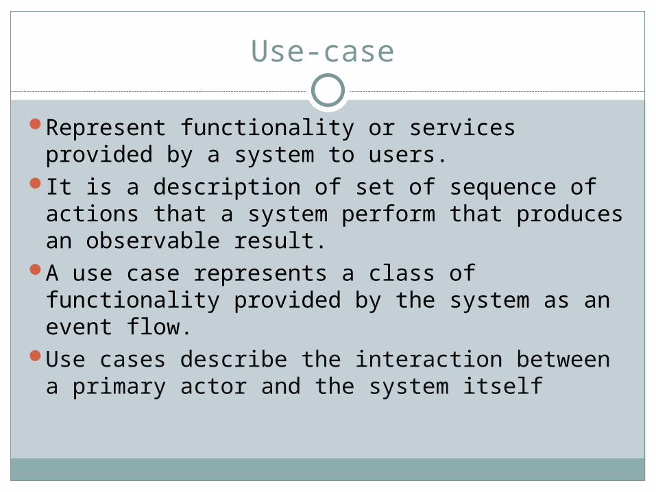
Use-case
Represent functionality or services provided by a system to users.
It is a description of set of sequence of actions that a system perform that produces an observable result.
A use case represents a class of functionality provided by the system as an event flow.
Use cases describe the interaction between a primary actor and the system itself

Use-case
The use case technique is used in software and systems engineering to capture the functional requirements of a system.
Each use case describes how the actor will interact with the system to achieve a specific goal.
One or more scenarios may be generated from each use case, corresponding to the detail of each possible way of achieving that goal.
Symbol : UML notation used to represent a
use-caseUML notation used to represent a
use-case

Use-case (Example)
Consider the same example again: In a university management system, a Student can submit the
assignments, the instructor marks those assignments and then uploads the result. The Student is allowed to view the Results.
Now, by recalling the definition of use-case, can you identify the use-cases in this System?
Submit AssignmentsMark AssignmentsUpload ResultsView Results

Use-case (Example/2)
The use-cases are linked with the functional requirements of this system. In this example : Student submit the assignments. Instructor marks the assignments. Instructor upload the marks. Student can view the marks.
It is now clear that how actors are interacting with different use-cases of this system.
Now, lets combine actors and use-cases in one diagram? Easy ?

Symbols in Use-Case Diagrams
ACTOR
USE-CASE
INTERACTION: denotes set of messages exchanged among objects
NOTES/COMMENTS

Use-Case Diagram (University Management System)
Student
Instructor
Submit Assignments
Mark Assignments
Upload Results
View Results
SYSTEM BOUNDARY
Package: University Management System

SOFTWARE ENGINEERINGBIT-8
Extending Use-Case Diagram

1 HOUR EXERCISE
Lab-Exercise (Extracting Use-cases)
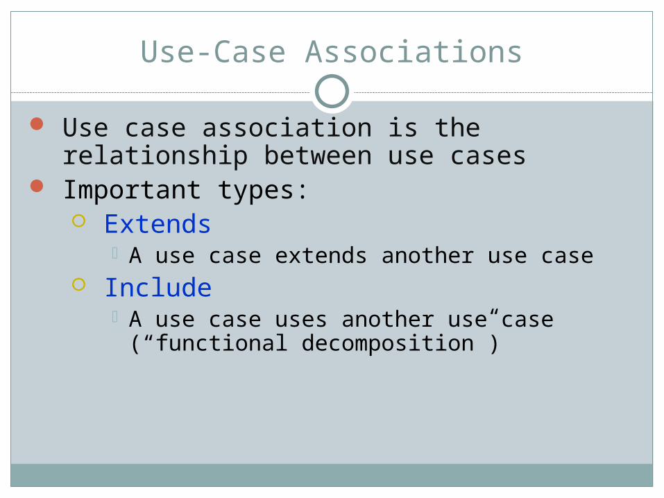
Use-Case Associations
Use case association is the relationship between use cases
Important types: Extends
A use case extends another use case Include
A use case uses another use case (“functional decomposition”)

<<Include>>: Functional Decomposition
A function in the original problem statement is too complex to be solved immediately.
What’s the Solution?Describe the function as the aggregation of a set of simpler functions The associated use case is decomposed into smaller use cases

<<include>> Example
The include association from Use Case A to Use Case B indicates that an instance of A performs all the behavior described in B
In <<include>> association, the base case cannot exist alone. It is always called with the supplier use case
<<include>> Base (A) Supplier (B)

<<Extend>> Association for Use Cases
Problem: The functionality in the original problem statement needs to
be extended.Solution:
An extend association from Use Case B to Use Case A indicates that B is an extension of A.
A B<<extend>>

Example
Example: The use case “ReportEmergency” is complete by itself
, but can be extended by the use case “Help” for a specific scenario in which the user requires help
Note: In an extend association, the base use case can be executed without the use case extension
Field Officer
ReportEmergency
<<extend>>
Help

Lab-Exercise
Read the following case :
Identify the actors Identify (extract ) the use cases Construct a proper use-case diagram (with proper symbols &
notations)
Case-Study
Consider the Library Management System of SEECS. A Student is allowed to issue books for a period of two weeks. Student can read newspapers/magazines in the library and can even access the databases for e-books. The Library Staff is responsible for maintaining the records of students and along with the issued books. The Staff marks an entry in the register whenever a student issue or return a book. A fine is charged on a student if he/she fail to return the book on time. The Librarian is there to manage the staff, check the records and prepare reports for DG/DEAN.


![[UML] UML, Metodologias e Ferramentas CASE us](https://img.pdfslide.net/doc/110x75/5571f34149795947648dbd59/uml-uml-metodologias-e-ferramentas-case-us.jpg)