Embed Size (px)
Citation preview

Software EngineeringProf. Rajib Mall
Department of Computer Science and EngineeringIndian Institute of Technology, Kharagpur
Lecture – 19Design Fundamentals
Welcome to this lecture. In the last lecture, we had towards the end we are discussing
about representing complex processing logic. If we write the complex processing logic in
the form of a text description, then it becomes difficult for the developers to understand,
for the testers to develop test cases. And also it is very likely that in a text base
description of a processing logic; certain combinations of combinations or variables and
their corresponding action might get missed.
And therefore, it is a good idea that during requirement specification, if we find that
logic is likely complex; then we have to represent it in the form of a decision tree and
table. We had seen that these are very simple semiformal techniques and we can very
easily develop the decision tree and decision table for any problem. Let us take an
exercise.
(Refer Slide Time: 01:53)
We want to develop decision table and decision tree for the following problem. Then see
here that the problem statement is very simple; but still the developers and testers might
find it bit confusion. If the flight is more than half-full and the ticket cost in the flight is
more than 3000 rupees, then free meals are served. But in domestic flight this rule does
not apply and all meals are charged on all domestic flights.
So, if you can see here the conditions here that one is that whether the flight is the one of
the conditions here is that whether the flight is a domestic flight. So, let me just write
here the flight is a domestic yes or no and then another condition is that ticket cost; ticket
cost greater than 3000 or not and then, we have to check whether the flight is half-full
occupancy greater than 50 percent; occupancy greater than 50 percent.
If it is a domestic flight, then free meal these are the actions free meal or charge meal. If
it is a domestic flight, then these are does not matter. We will have to charge the meal;
but the flight is not domestic and the ticket cost is let us say less than 3000, then these
will not matter. It will be charged meal. If the flight is not a domestic flight and the ticket
cost is more than 3000 and occupancy rate is less than 50 percent, then again we charge
the meal.
But if is not a domestic flight and the ticket cost is more than 3000 and the occupancy is
also more than 50 percent; then we give free meal. So, as you can see here that this gives
a very conceptually meaningful representation of this conditions.
But then, remember that this is still a whether simple condition that we are trying to
represent here as an example; but the conditions can become much more complex and
therefore, the true use the decision table can come out. Elevate to you as exercise to
develop the decision tree representation for the same problem. Now let us conclude our
discussion on requirement specification and let us see proceed to look at software design
aspects.
Because typically in the life cycle after requirements design tasks are taken out will start
with some very basic issues in software design and then, we look at the procedural and
object oriented design principles. We will look at now software design and we will start
with some very basic issues in software design. The designed activities are under taken
once the requirement is complete, SRS document is written in the traditional models.
(Refer Slide Time: 07:00)
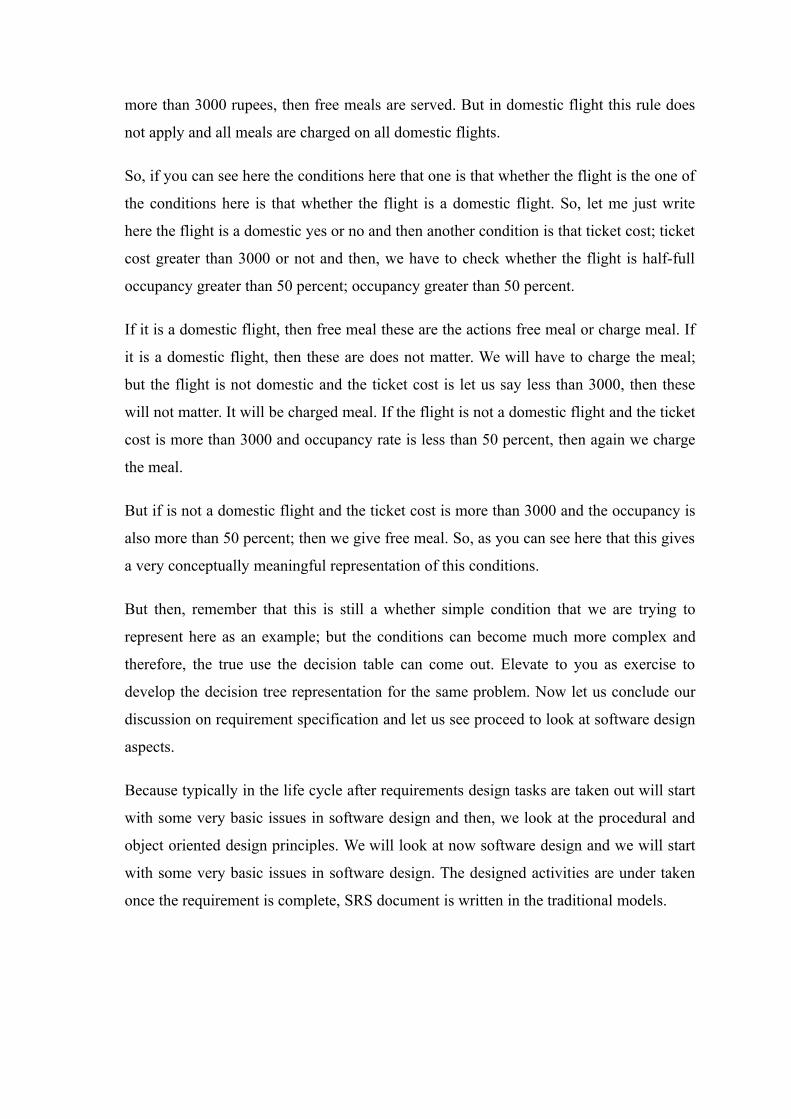
During the design phase, we have the SRS documents as the input and then do some
activities during the design and then, we will come up with the design document at the
end of the design phase. The design document can be taken up and coding can start and
our design document is good; if the coders can just take it, the programmers can take it
and can start writing the code easily. This is just a graphic representation that during the
design phase.
So, this is the design phase, design phase and the input is the SRS document with
performs some designer activities and then, at the end of the phase we have the design
document. Now let us see at the end of the phase what are the documents we should have
inhouse? What we should prepare during the design phase and then will address the
question how to prepare those?
(Refer Slide Time: 08:43)
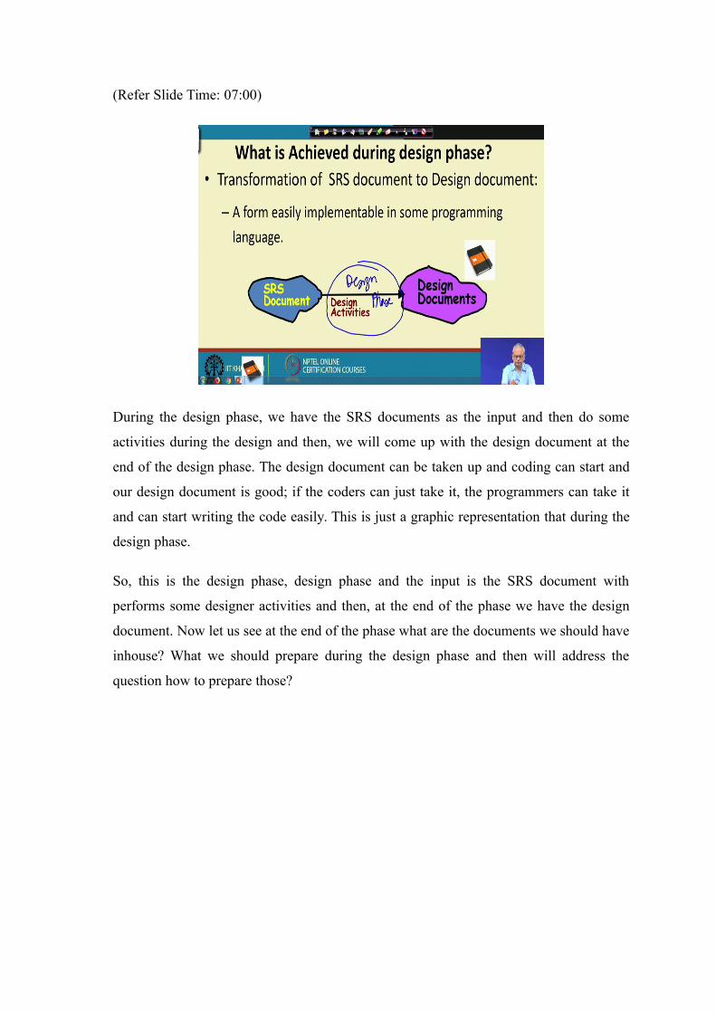
Typically, we have the module structure in a procedural design or the class structure in a
object oriental design. The control relationship among the modules, this in a procedural
designs and similarly in a object oriental design, we have in location sequences among
different classes.
So, this is the call relationship or invocation relationship between the modules and the
classes. The interface that is what that exactly is a given as a parameter when there is a
call functional call or a method call that we call the interface among the modules. So,
this is basically the data items that are exchanged between the modules. And also we
need to design the data structure of the individual modules and also the algorithms that
would be used.
So, these are all the different items that must be designed during the design phase that is
the module structure, the call relationship among the module in a object oriented way we
will see it little later that this is a class structure, the invocation relationship among the
classes. And then, the interface among the modules that is what parameters, they pass or
the data items that are exchanged and the different modules. The data structures of the
individual modules and then the algorithms for the individual modules.
(Refer Slide Time: 10:53)
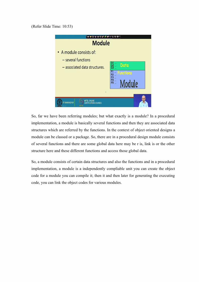
So, far we have been referring modules; but what exactly is a module? In a procedural
implementation, a module is basically several functions and then they are associated data
structures which are referred by the functions. In the context of object oriented designs a
module can be classed or a package. So, there are in a procedural design module consists
of several functions and there are some global data here may be r is, link is or the other
structure here and these different functions and access those global data.
So, a module consists of certain data structures and also the functions and in a procedural
implementation, a module is a independently compliable unit you can create the object
code for a module you can compile it; then it and then later for generating the executing
code, you can link the object codes for various modules.
(Refer Slide Time: 12:16)
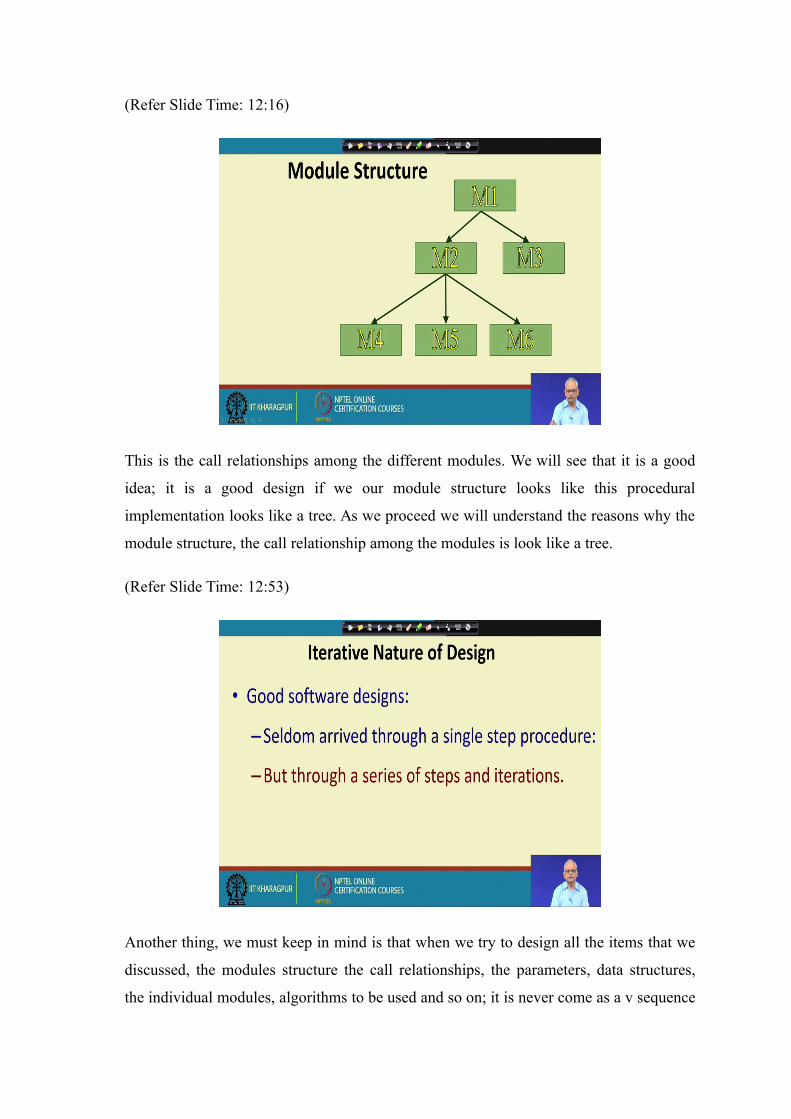
This is the call relationships among the different modules. We will see that it is a good
idea; it is a good design if we our module structure looks like this procedural
implementation looks like a tree. As we proceed we will understand the reasons why the
module structure, the call relationship among the modules is look like a tree.
(Refer Slide Time: 12:53)
Another thing, we must keep in mind is that when we try to design all the items that we
discussed, the modules structure the call relationships, the parameters, data structures,
the individual modules, algorithms to be used and so on; it is never come as a v sequence

single sequence sub steps. Design is a very intellectually stimulating work and need to do
several iterations.
(Refer Slide Time: 13:30)
So as we look at the procedural and object oriented design, we will see that we will have
to iterate our several steps. Look at evaluate designs alternatives and then we will come
up with a good design. Now let us look at what are the stages in the design? There are
main 2 stages in the design phase; one is called as the high-level or the preliminary
design and the other is called as the detailed design.
The high-level design is also called as architectural design and then we have the design
detailed design. So it is a preliminary or high-level design or a architectural design and
then, we have the detailed design. Next we will see that there is a significant difference
in the steps, in the procedural and object oriented design and the meaning and scope of
these two, very quietly widely between procedural and object oriented design, the
architectural design and the detailed design.
Even in the procedural design, there are several methodologies. We look at one of the
methodology; but there exists dozens of methodologies. Even among the methodologies,
there is quite a variation in what exactly should be done the architectural design and what
exactly to be done in the detailed design. We will look those issues little later.
(Refer Slide Time: 15:36)
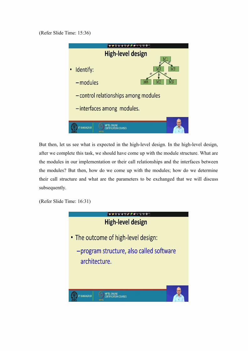
But then, let us see what is expected in the high-level design. In the high-level design,
after we complete this task, we should have come up with the module structure. What are
the modules in our implementation or their call relationships and the interfaces between
the modules? But then, how do we come up with the modules; how do we determine
their call structure and what are the parameters to be exchanged that we will discuss
subsequently.
(Refer Slide Time: 16:31)
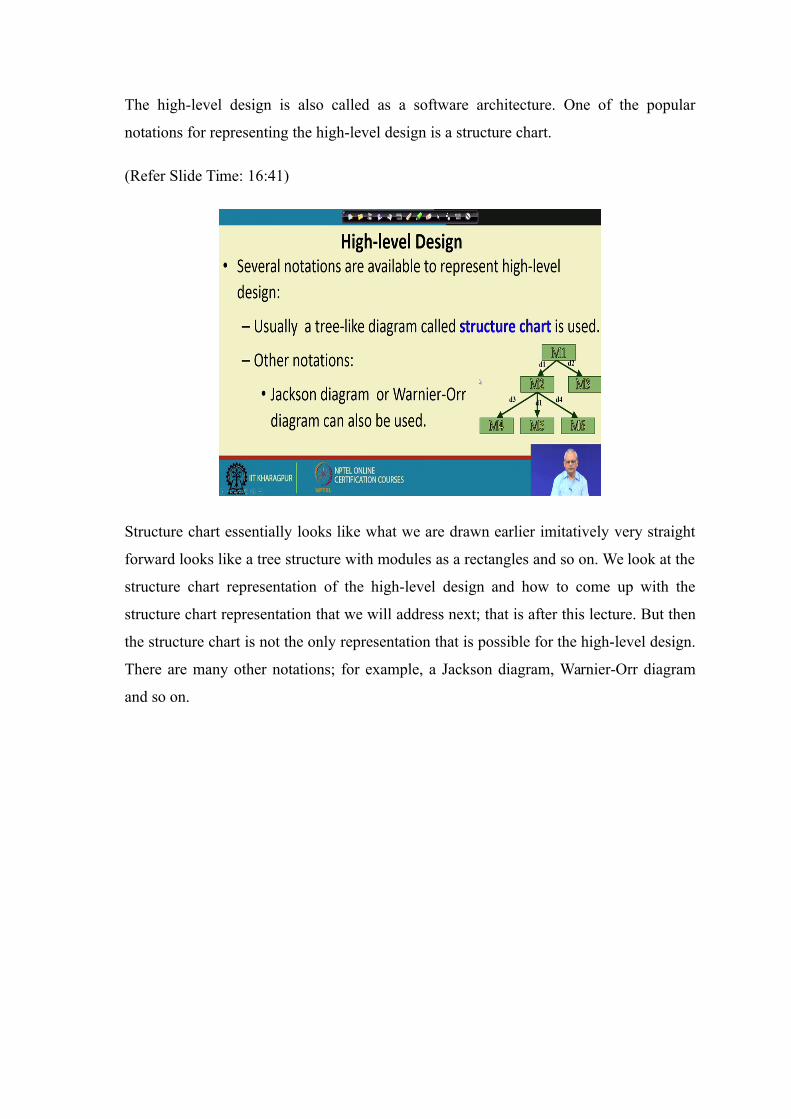
The high-level design is also called as a software architecture. One of the popular
notations for representing the high-level design is a structure chart.
(Refer Slide Time: 16:41)
Structure chart essentially looks like what we are drawn earlier imitatively very straight
forward looks like a tree structure with modules as a rectangles and so on. We look at the
structure chart representation of the high-level design and how to come up with the
structure chart representation that we will address next; that is after this lecture. But then
the structure chart is not the only representation that is possible for the high-level design.
There are many other notations; for example, a Jackson diagram, Warnier-Orr diagram
and so on.
(Refer Slide Time: 17:39)
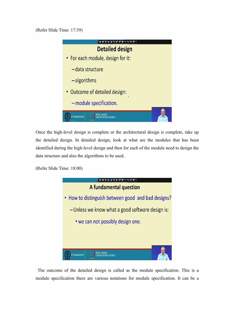
Once the high-level design is complete or the architectural design is complete, take up
the detailed design. In detailed design, look at what are the modules that has been
identified during the high-level design and then for each of the module need to design the
data structure and also the algorithms to be used.
(Refer Slide Time: 18:00)
The outcome of the detailed design is called as the module specification. This is a
module specification there are various notations for module specification. It can be a
simple text based notation in formal notation. It can be slightly semi formal notations
where represent the data structures and the algorithms.
But, so far you just looked at some simple concepts that during design, we need to have
the high-level or the architectural design that is the first step and once the architectural
design is complete. We have the module structure calling location, call structure, the
invocation among the different modules and the interfaces among modules that is the
data exchange between different modules. And we represent that in a tree like diagram a
structure chart or something and after that take up the detailed design where we design
the data structure of the individual modules and also the algorithms.
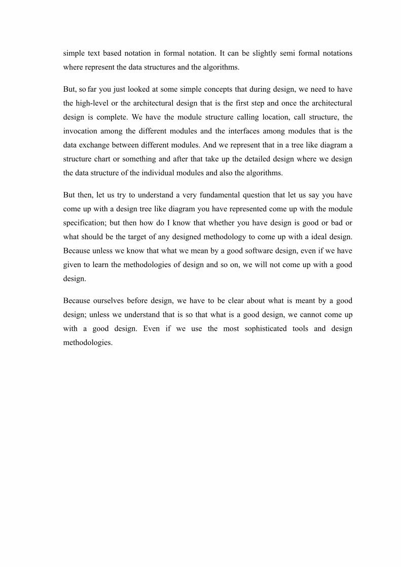
But then, let us try to understand a very fundamental question that let us say you have
come up with a design tree like diagram you have represented come up with the module
specification; but then how do I know that whether you have design is good or bad or
what should be the target of any designed methodology to come up with a ideal design.
Because unless we know that what we mean by a good software design, even if we have
given to learn the methodologies of design and so on, we will not come up with a good
design.
Because ourselves before design, we have to be clear about what is meant by a good
design; unless we understand that is so that what is a good design, we cannot come up
with a good design. Even if we use the most sophisticated tools and design
methodologies.
(Refer Slide Time: 20:32)
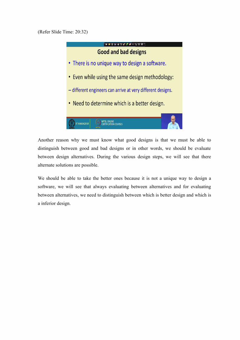
Another reason why we must know what good designs is that we must be able to
distinguish between good and bad designs or in other words, we should be evaluate
between design alternatives. During the various design steps, we will see that there
alternate solutions are possible.
We should be able to take the better ones because it is not a unique way to design a
software, we will see that always evaluating between alternatives and for evaluating
between alternatives, we need to distinguish between which is better design and which is
a inferior design.
(Refer Slide Time: 21:30)
The first thing is that another reason is that different developers. By using the same
methodology they can come with very different designs in the end. We should know, we
should able to tell how good is the design or we can select the better design if we have
different designers come up with different designs.
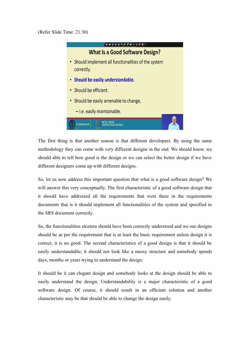
So, let us now address this important question that what is a good software design? We
will answer this very conceptually. The first characteristic of a good software design that
it should have addressed all the requirements that were there in the requirements
documents that is it should implement all functionalities of the system and specified in
the SRS document correctly.
So, the functionalities etcetera should have been correctly understood and we our designs
should be as per the requirement that is at least the basic requirement unless design it is
correct, it is no good. The second characteristics of a good design is that it should be
easily understandable; it should not look like a messy structure and somebody spends
days, months or years trying to understand the design.
It should be it can elegant design and somebody looks at the design should be able to
easily understand the design. Understandability is a major characteristic of a good
software design. Of course, it should result in an efficient solution and another
characteristic may be that should be able to change the design easily.
Because during development lot of changes happen, requirement change and based on
the design change and even after the development the software continues to change and
therefore, our design should be such that we would be able to change any part of the
software and that helps in maintaining the software. But we have highlighted one aspect
here is that the design should be easily understandable and it turns out that this is one of
the most important characteristics of a good software design that it should be easily
understandable.
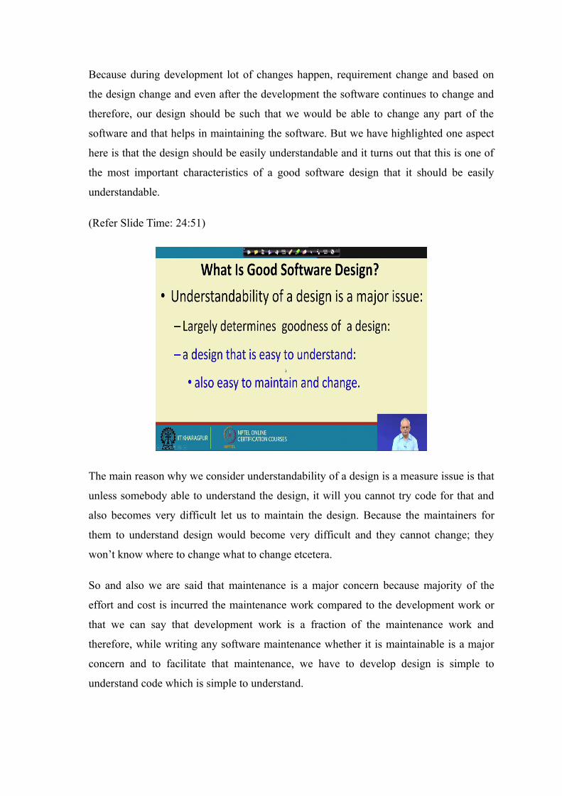
(Refer Slide Time: 24:51)
The main reason why we consider understandability of a design is a measure issue is that
unless somebody able to understand the design, it will you cannot try code for that and
also becomes very difficult let us to maintain the design. Because the maintainers for
them to understand design would become very difficult and they cannot change; they
won’t know where to change what to change etcetera.
So and also we are said that maintenance is a major concern because majority of the
effort and cost is incurred the maintenance work compared to the development work or
that we can say that development work is a fraction of the maintenance work and
therefore, while writing any software maintenance whether it is maintainable is a major
concern and to facilitate that maintenance, we have to develop design is simple to
understand code which is simple to understand.
Understandability of the design is a major issue require significant attention by the
developers sorry the designers and also every design methodology helps to come up with
good design which is easily understandable.
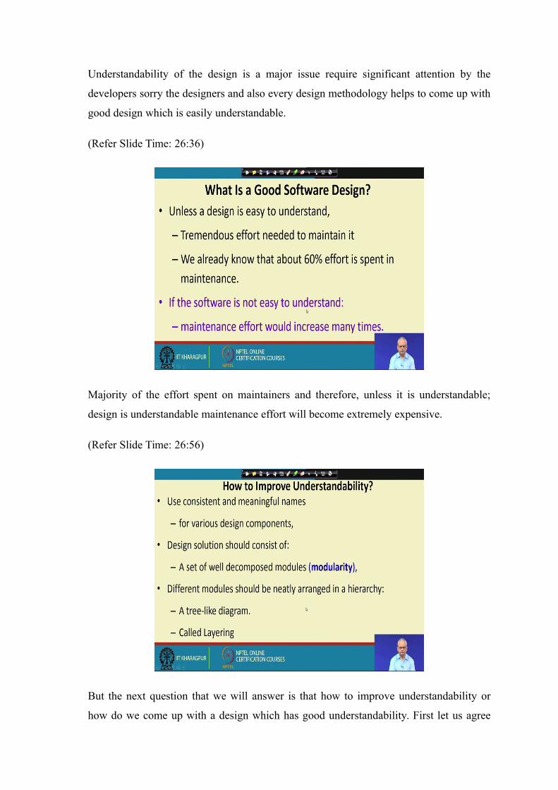
(Refer Slide Time: 26:36)
Majority of the effort spent on maintainers and therefore, unless it is understandable;
design is understandable maintenance effort will become extremely expensive.
(Refer Slide Time: 26:56)
But the next question that we will answer is that how to improve understandability or
how do we come up with a design which has good understandability. First let us agree

that one of the most desirable characteristic of any design solution is that it should be
very easy to understand and then, we will have to address the question that how do we
come up with a design that has good understandability?
This is a issue which has some details that we must understand and in the next lecture,
we will address this very basic issue that how does one come up with a design that will
have good understandability.
We will stop here and continue in the next lecture.