Embed Size (px)
Citation preview

Faculty of Engineering – University of Porto
Software for a Gasoline Internal Combustion Engine
João Filipe Matos Silva
PROVISORY VERSION
Dissertation / Project of
Integrated Master in Electronic and Computer Engineering
Major Automation
Supervisor: Prof. Dr. Armando Luis Sousa Araújo
Company Supervisor: Rob J. Barnes

ii
June, 2010

iii

iv
© João Silva, 2010

v
Abstract
Internal combustion engines are still the most common and reliable power source
forpower-propelled vehicles. The easiness of re fuelling and its inherent autonomy makes it
hard to find a replacement. The alternatives, such as electric vehicles are becoming a more
and more serious point of investigation,but are still finding barriers in autonomy vs.
performance when compared with the internal combustion.
Nevertheless, the efficiency of the internal combustion engine is still far from great when
compared with electric motor for example, it’s estimated that an internal combustion engine
has efficiency of about 40 to 50%, while the electric motor reaches easily 95% and more.
The way to try to make the use of internal combustion engines less harmful to the
environment until a definitive and concrete solution is achieved to completely replace this
type enginelies inthe advancesregarding the engine management systems. These systems
intend to increase efficiency at its maximum while reducing fossil fuel consumptions to a
minimum.
The following document describes the project of creating software for an Electronic
Control Unit to provide Engine Management to a 4 cylinder normally aspirated gasoline
internal combustion engine.
General overviews about theory of operation of a spark ignition (SI) engine are described
as well as the function of main components relevant for this project.
The automotive industry and its development departments are among the high-end in the
research and demands for new technologies and breakthroughs. Several tools to help in
development of control software for the automotive industry are presented.
This project tries to give an insight on the basic foundations of creating software for the
automotive industry and its requirements.

vi

vii
Acknowledgments
I would like to take this space to thank the several people who in one way or another
helped me reach here, the final stage of my academic life.
I like to thank to my supervisor, Prof Dr. Armando Araújo, for the help and time to answer
my questions, and giving valuable inputs on the way to follow to reach this point.
I thank to people from Vocis Driveline Controls the possibility of this internship, accepting
me here and allow me to learn and grow in so many ways.
A special word to my company supervisor Rob J. Barnes, without whom I wouldn’t be
here, the enormous amount of time dedicated to help and tutoring me was invaluable.
I would like to thank to all my family to make possible the fact I am graduating in the
degree I want, and the fact they helped me bare the time abroad.
Last but not least I would like to thank to all my friends the support, the patience and the
jokes with all those days and nights of work and fun, luckily for me it would be too long to
name it all, but you know who you are.

viii
ix
Table of Contents
Abstract ........................................................................................ v
Acknowledgments ...........................................................................vii
Table of Contents............................................................................ ix
List of Figures ................................................................................ xi
List of Tables ................................................................................ xiv
Abbreviations and Symbols ............................................................... xvi
Chapter 1....................................................................................... 1
Introduction ................................................................................... 1
1.1 Project Context ..................................................................................... 1
1.2 The Company........................................................................................ 2
1.3 An overview on the studied subjects ............................................................ 3
1.3.1 Internal combustion Engines ................................................................. 3
1.3.2 FUEL management system .................................................................... 7
1.3.3 Ignition management system................................................................. 8
1.3.4 Electronic control unit, ECU................................................................ 11
1.4 Structure of Report............................................................................... 13
Chapter 2......................................................................................17
Hardware and Set Up .......................................................................17
2.1 Engine Management System, EMS-12........................................................... 17
2.2 Wiring Connections ............................................................................... 19
2.2 Test Rig ............................................................................................ 22
2.3 Test Car ............................................................................................ 28

x
2.4 Set up ............................................................................................... 29
Chapter 3......................................................................................33
Software Development Tools..............................................................33
3.1 Lauterbach Debugger ............................................................................. 33
3.2 ETAS ASCET......................................................................................... 34
3.3 VECTOR CANape ................................................................................... 36
Chapter 4......................................................................................39
Microprocessor and Automotive Function Set .........................................39
4.1 Microprocessor ..................................................................................... 39
4.2 ETPU Engine........................................................................................ 39
4.3 eTPU Position (CRANK and CAM) functions .................................................... 41
4.5 ETPU FUEL function ............................................................................... 43
4.6 ETPU SPARK function ............................................................................. 45
Chapter 5......................................................................................49
Implementation ..............................................................................49
5.1 Software Requirements........................................................................... 49
5.2 Fuel Pump Module................................................................................. 51
5.3 IOP Module ......................................................................................... 53
5.4 SPK Module ......................................................................................... 54
5.5 Throttle ............................................................................................. 57
5.6 Fuel Control ........................................................................................ 60
Chapter 6......................................................................................67
Tests ...........................................................................................67
Chapter 7......................................................................................69
Results .........................................................................................69
Future Work ..................................................................................73
Conclusions ...................................................................................75
References....................................................................................77

xi
List of Figures
Figure 1.1 - Engine cut view .............................................................................. 4
Figure 1.2 - Time belt and alternator belt.............................................................. 5
Figure 1.3 - Clutch Diagram............................................................................... 6
Figure 1.4 - Typical carburetor........................................................................... 7
Figure 1.5 - Ignition on combustion chamber .......................................................... 8
Figure 1.6 - Distributor Schematic ....................................................................... 9
Figure 1.7 - Emissions and efficiency variation with spark timing..................................10
Figure 1.8 - DCI vs. EDIS ignition system ...............................................................11
Figure 1.9 - Major ECU components ....................................................................12
Figure 2.1 - EMS-12 Overview............................................................................17
Figure 2.2 - IGBT for ignition coil drive ................................................................18
Figure 2.3 - HE sensor signal conditioning .............................................................18
Figure 2.4 - VR signal conditioning......................................................................18
Figure 2.5 - Wire Harness with original controller....................................................19
Figure 2.6 - Connections from original controller to EMS-12........................................21
Figure 2.7 - List of connection of new connector created with 18 pin ............................21
Figure 2.8 - Test Rig Overview ..........................................................................22
Figure 2.9 - Crank signal from VR sensor (red) and Cam signal (yellow) ..........................23
Figure 2.10 - Crank Signal (red) and Cam signal (yellow)............................................23

xii
Figure 2.11 - Fire Events on a wasted spark ignition system ....................................... 25
Figure 2.12 - Test Rig Ignition system.................................................................. 25
Figure 2.13 - Fuel Trigger(red) and Cam signal (yellow) ............................................ 26
Figure 2.14 - Test Rig Connection Box ................................................................. 27
Figure 2.15 - Test Car .................................................................................... 28
Figure 2.16 - Engine Overview .......................................................................... 29
Figure 2.17 - Coil Pack added with distributor in background...................................... 30
Figure 2.18 - O2 Sensor and main specifications ..................................................... 31
Figure 2.19 Crank Attempt .............................................................................. 32
Figure 3.1 - Lauterbach .................................................................................. 34
Figure 3.2 - Ascet project layers........................................................................ 35
Figure 3.3 - Ascet overview of project components and OS process .............................. 36
Figure 3.4 - CANape set up to understand what is happening ...................................... 37
Figure 4.1 - CRANK position wheel 36-1 configuration .............................................. 42
Figure 4.2- Time diagram of a simple injection pulse ............................................... 44
Figure 4.3 - Complex fuel injection pulse ............................................................. 44
Figure 4.4– Spark Event .................................................................................. 46
Figure 5.1 – Formula edit in ASCET ..................................................................... 51
Figure 5.2 - Fuel Pump State Diagram ................................................................. 52
Figure 5.3 - Fuel Pump Relay Control .................................................................. 53
Figure 5.4 – Throttle position sensor transfer function. ............................................. 54
Figure 5.5 - IOP Software ................................................................................ 54
Figure 5.6 - Spark Base Map ............................................................................. 55
Figure 5.7 - SPK Angle Calculation...................................................................... 56
Figure 5.8 - SPK Spark software control ............................................................... 56
Figure 5.9 - Spark angles load into SPARK function .................................................. 57
Figure 5.10 - Throttle Duty Cycle control ............................................................. 58
Figure 5.11 – Dither filter ................................................................................ 59
Figure 5.12 – Throttle control for idle speed.......................................................... 60

xiii
Figure 5.13 - FUEL Total Time Calculation ............................................................60
Figure 5.14 - Fuel Pulse width calculation.............................................................61
Figure 5.15 - Fuel base map .............................................................................61
Figure 5.16 - Fuel..........................................................................................62
Figure 5.17 - Open Loop fuel rules......................................................................63
Figure 5.18 - Fuel Overrun ...............................................................................63
Figure 5.19 - Fuel time output ..........................................................................64
Figure 5.20 - Fuel limiting rpm ..........................................................................64
Figure 5.21 - Fuel flood clear............................................................................64
Figure 7.1 - Engine Position Status......................................................................70
Figure 7.2 – Fuel injection variable with load.........................................................70
Figure 7.3 – Spark Angles in CANape....................................................................70
Figure 7.4 - Visible Sparks in Test Rig ..................................................................71
Figure 7.5 – Fuel O2 Sensor and Fuel Inject Time ....................................................71

xiv
List of Tables
Table2.1— KL Designation. .............................................................................. 20

xv
xvi
Abbreviations and Symbols
ADC Analogue to Digital Converter
A/F Air Fuel Ratio
CT Coolant Temperature
BDC Bottom Dead Centre
ECU Electronic Control Unit
EMS Engine Management System
ETPU Enhanced Timer Processor Unit
GDI Gasoline Direct Injection
IAT Inlet Air Temperature
ICE Internal Combustion Engine
IGBT Insulated Gate Bipolar Transistor
MAF Mass Air Flow
O2 Oxygen Sensor
SI Spark Ignition
TDC Top Dead Centre
TPS Throttle Position Sensor
VVT Variable Valve Timing

xvii

xviii

Chapter 1
Introduction
This chapter presents the project and its goals, the company where it was developed and a
generic overview about the studied subjects. At the end of this chapter an overview of the
report is presented.
1.1 Project Context
This project took place at Vocis Driveline Controls[1]in order to fulfil the requirements to
obtain the degree of Masters in Electronics and computer Engineer at Faculty of Engineering –
University of Porto. The exchange occurred by the Erasmus Placement program.
The following description summarizes the motivation of the company and the main
proposed goals for the final application.
Vocis have designed an engine management electronic control unit (ECU), based on the
Freescale ‘Black Oak’ MPC555 [2] and Freescale ‘Copperhead’ MPC5554 [3]microprocessors, for
a 12 cylinders, spark ignited, internal combustion engine (ICE). This ECU is designated ‘EMS-12’.
Vocis have the need to createa first engine control application for the ECU, and have chosen a
4 cylinder, spark ignited, Volkswagen Golf as the target for this purpose. To assist in
creatingthe control software, Vocis have also created a bench testing rig consisting of most of
the sensors and actuators present on the target engine. Summarizing the target application
should be capable of:
• Interpretation and failure checking of analogue and digital inputs.
• Synchronization of a Time Processor Unit (TPU) with an internal combustion engine
using crankshaft and camshaft position sensors.

2 Introduction
• Control of fuel injectors to inject fuel at a desired crankshaft angle for a specified
time period.
• Control of ‘wasted spark’ ignition coils to fire cylinders at specified angles.
• Closed loop fuelling control using an exhaust gas oxygen sensor.
• Control of an electronic throttle unit.
The main areas of study and application can be described as:
• Knowledge and understanding of microprocessor based systems for study and
identification of the MPC555/MPC5554 architecture.
• Implementation of a custom Time Processor Unit ,TPU/eTPU, software for the
processors.
• Synthesis and proposal of a low level ‘C’ code program for the processors.
• Application of the ETAS ASCET-SD programming and modelling language, and the
generation of fixed point ‘C’ code.
• Application of the Vector CANape tool, and the Controller Area Network (CAN)
vehicle network system.
• Integration of all developed subsystems in the design of a complete control system
for the 4 cylinder, spark ignited, ICE.
1.2 The Company
Vocis was formed in September 2006 by five highly-experienced automotive engineers with
a proven track-record of project delivery in the field of transmission and driveline systems for
all types of passenger cars and trucks. The aim was to provide an alternative source of
expertise for vehicle OEM and tier one company to tap into.
Shortly after it's formation, Vocis was approached by GrazianoTransmissioni, member of the
Oerlikon group [4].After negotiations a majority shareholding is owned by OerlikonGraziano
Drive Systems. However Vocis has authority to work with anyone in the marketplace.
Within five months after formation, Vocis created a demonstrator vehicle (based on a wet-
clutch dual clutch transmission) to showcase their control system expertise. Vocis designed
their own controller hardware capable of running sophisticated control methods. Vocis
developed a complete suite of dual clutch transmission control software (Driving Strategy, Shift
Sequencing, Clutch Control, Synchronizer Control, Engine Interface and Diagnostics) from

An Overview on Studied Subjects3
scratch. Vocis have continued development of control methods since the first demonstrations in
March 2007, taking on board comments from those who have driven the car.
In addition to its own demonstrator car, Vocis has delivered a number of projects for
external clients.
Vocis Driveline Controls clients are some of the best-known OEM and tier one organizations
in the automotive industry - Vocis work for them in the following areas:
• Production-intent programmes for controllers and/or software.
• Designs for transmissions and driveline mechanical and hydraulic systems.
• Specification of electronic hardware and system components.
• Concept studies for future transmissions and drivelines.
• Specification of software for safety-critical driveline systems.
For test purposes the company holds a workshop in MIRA[9]proving ground.
This project took place in these facilities. The workshop is equipped with all the necessary
tools and equipment to help on any kind of work in a car. It’s here where the company makes
the tests with/to all their projects. The proving ground is a big complex with several different
tracks for different tests. The confidentiality is taken very seriously as cameras of any kind
(including cell phones) are not allowed in the proving ground. This proving ground is a test base
for several of the most known manufactures in the world.
1.3 An overview on the studied subjects
1.3.1 Internal combustion Engines
Internal combustion engines (ICE) are so deeply rooted in our everyday lives, that many
don't even wonder what’s under the hood of their car.
Due to its popularity, the ICE knew an unimaginable growth in research and development
which lead to better and more efficient engines.
The list of innovations and performance improvements isextremely vast and therefore
beyond the scope of this document.

4 Introduction
Although the peripherals of the ICE may have been changed, the materials used improved,
and the management systems turned more accurate, the functional description of the four
strokes internal combustion engine remains the same.
Figure 1.1 - Engine cut view
It is named four strokes after Otto [5] named the four stages of a petrol engine. In order to
produce power, these four strokes occur in every cylinder of the engine. They are named:
• Admission.
• Compression.
• Explosion (or ignition).
• Exhaust.
In admission stage the intake valve opensso that the air fuel mixture inserted into the
cylinder chamber (via electronic injection or carburetor into the intake manifold or directly in
the cylinder).Once this happens the intake valve is closed.

An Overview on Studied Subjects5
On compression, the piston is moving upwards to top dead centre (TDC), with both cylinder
valves closed, this reduces the volume of the cylinder chamber and the air fuel mixture
becomes compressed.
The explosion stage is where the mixture is ignited (via the spark plugs) and creates force
into the piston to go down faster (explosion). There are a lot of parameters that influence
directly or indirectly the timing and the method for calculating the spark occurrence. There are
systems with multi sparks and techniques for changing the timing. The difference systems can
be mechanical distributors or even complex microprocessor computations, that makes
thousands of calculations, to give spark advance. It’s in this stage, of engine cycle, that torque
is generated by the force pushing the piston down.
On the last stage, of engine cycle, the exhaust valves open and the gases from the
combustion are expelled into the exhaust manifold.
Figure 1.2 - Time belt and alternator belt
Each engine has its own timing, that corresponds to the moment of opening and closing of
each valve (for each cylinder) and that’s why the timing belt is so important. If a piston is on
TDC with any of the valves open this will bend the valve and completely destroy the engine.
The valves are opened by “bumps” in the camshaft, which are connected to the crankshaft
by the time belt, some manufactures started to create systems with dual camshafts that opens
the intake and the exhaust valves separately, and this allows larger range of control.
There are systems to change the timing of the valveswith some manufactures choosing
different techniques (Toyota BWM Nissan, Honda). At high engine speeds, an engine requires
large amounts of air. However, the intake valves may close before all the air has been given a

6 Introduction
chance to flow in, reducing performance. On the other hand, if the cam keeps the valves open
for longer periods of time, as with a racing cam, problems start to occur at the lower engine
speeds. This will cause unburned fuel to exit the engine since the valves are still open. This
leads to lower engine performance and increased emissions. For this reason, pure racing
engines cannot idle at the low speeds (around 800 rpm) expected of a road car, and idle speeds
of 2,000 rpm are not unusual.
Pressure to meet environmental goals and fuel efficiency standards is forcing car
manufacturers to turn to variable valve timing (VVT) as a solution. Most simple VVT systems
advance or retard the timing of the intake or exhaust valves. Others (like Honda's VTEC) switch
between two sets of cam lobes at a certain engine RPM. Furthermore Honda's i-VTEC can alter
intake valve timing continuously.
The torque and power are passed to the outside of the engine by the crankshaft (which is
solider with the pistons). In a standard car this shaft is the input to the transmission and
gearbox systems that will transfer power to the wheels; the clutch that the normal everyday
driver actuates by pressing a pedal is no more than the connection between these two systems.
Figure 1.3 - Clutch Diagram
The most common type of clutch is no more than a disc (or several), made from similar
material as brake pads, and with a frictional force that attaches the gearbox to the crankshaft.
Some springs and release bearings allow the smooth connection or interruption of this system as
shown in Figure 1.3.
Since early days in engine building and control, the aim to make cars more efficient and
powerful was a need and a passion. The amount of progress achieved in engine management
systems(EMS), is mind blowing. So, the aim of this part is to provide the reader a description of

An Overview on Studied Subjects7
what’s involved in EMS, how and why the evolutions took place and to present a standard
approach to the techniques able to make an EMS.
Putting it in simple words, a management system will consist in something that controls
(therefore manages) the system in question. In this case the first things that were controlled, in
a regular petrol engine, were injection and ignition systems.
As explained before the engine always had these two systems, in order to be able to
function correctly, but independently they were targets of enormous changes along the
decades having evolved from purely mechanical to fully electronic systems.
1.3.2 FUEL management system
Air/fuel ratio (A/F), or the amount of injected fuel into the cylinder chamber, was for many
years, made by the purely mechanical system known as the carburetor[6]. This device
externally blends air and fuel and inserts the mixture into the intake manifold.
Figure 1.4 - Typical carburetor
This device proved to be reliable and lasted many years as the predominant mechanism for
this job. The ability to tune it manually by mechanical means still attracts many enthusiasts
that use them on old cars. The carburetor was refined over the years, but reached a point
where emission control and fuel cuts demands were too strict for it. Its performance limits lead
to the search for new alternative systems for air/fuel mixture control.

8 Introduction
With electronics breakthroughs and the constant demanding from the automotive industry
to present better, more reliable and efficient products electronic injection systems appeared
naturally.
There are several possible configurations in injection systems.The most common used is
called single point injection. This system consists in a single system (carburetor or injector)
that allows the fuel passage to the intake manifold.Following this the opening of the intake
valves makes the admission of fuel into combustion chamber possible.
Another system is the multi-point injection. This time there are several injectors or
carburetors (normally one per cylinder) and their individual control allows the injection of fuel
into the intake of each cylinder separately.
These two systems may be configured in groups, where several injectors work
simultaneously, this happens normally in engines with a high number of cylinders.
The latest innovation for multi-point injection is the gasoline direct injection (GDI), where
the injector is placed inside the combustion chamber. There is a wide range of control
possibilities for these systems.The timing and amount of fuel can be much more efficient
controlled since the injector is localized close the spark system.
1.3.3 Ignition management system
Ignition systems are responsible for delivering a spark in order to ignite the mixture inside a
compressed volume, namely the cylinder. Making combustion of A/F mixture forces it to expand
and increase its volume; this will push the piston down and produce torque.
Figure 1.5 - Ignition on combustion chamber

An Overview on Studied Subjects9
Again, as the fuel system, ignition started to be almost purely mechanical so the first
systems consisted on the so called distributor, Figure 1.6 .
Figure 1.6 - Distributor Schematic
This system consists ofa rotor (rotates with camshaft), provided with shaped contacts and a
mechanical circuit breaker that opens and closes an electrical circuit withan autotransformer,
known as the ignition coil. Current in the ignition coil is provided by a battery and this current
is interrupted, at calculated angular positions, to give the spark. These calculations are purely
mechanical.
The corrections consist in moving the spark time relatively to TDC. With engine rpm
increasing and the combustion time being almost the same, it’s easily understandable that the
spark needs to occur early (in degrees scale means more degrees before TDC) in order the
combustion occurs at an optimal time to push the piston down.In purely mechanical systems
this is accomplished with centrifugal mechanisms that adjust the contactswith shaft speed.
Vacuum mechanisms are used to change timing with load, which in this case can be seen as
function of the amount of air (or pressure) in the intake manifold, the spark will be closer to
TDC with a load increase.
The ignition system knew a lot of progresses during the time. The exact time to provide a
mixture with a spark is crucial to the best performance, efficiency and durability of an engine.
10 Introduction
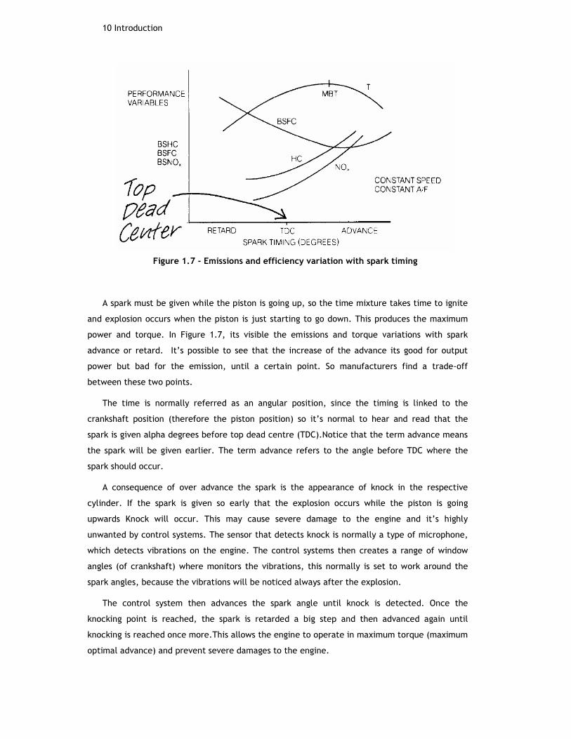
Figure 1.7 - Emissions and efficiency variation with spark timing
A spark must be given while the piston is going up, so the time mixture takes time to ignite
and explosion occurs when the piston is just starting to go down. This produces the maximum
power and torque. In Figure 1.7, its visible the emissions and torque variations with spark
advance or retard. It’s possible to see that the increase of the advance its good for output
power but bad for the emission, until a certain point. So manufacturers find a trade-off
between these two points.
The time is normally referred as an angular position, since the timing is linked to the
crankshaft position (therefore the piston position) so it’s normal to hear and read that the
spark is given alpha degrees before top dead centre (TDC).Notice that the term advance means
the spark will be given earlier. The term advance refers to the angle before TDC where the
spark should occur.
A consequence of over advance the spark is the appearance of knock in the respective
cylinder. If the spark is given so early that the explosion occurs while the piston is going
upwards Knock will occur. This may cause severe damage to the engine and it’s highly
unwanted by control systems. The sensor that detects knock is normally a type of microphone,
which detects vibrations on the engine. The control systems then creates a range of window
angles (of crankshaft) where monitors the vibrations, this normally is set to work around the
spark angles, because the vibrations will be noticed always after the explosion.
The control system then advances the spark angle until knock is detected. Once the
knocking point is reached, the spark is retarded a big step and then advanced again until
knocking is reached once more.This allows the engine to operate in maximum torque (maximum
optimal advance) and prevent severe damages to the engine.

An Overview on Studied Subjects11
The naturally development from the ignition system was to eliminate the mechanical parts
of their own system. Gaps and time aging of contacts cause several problems in ignition system
as inaccurate timing and misfires. So, the new systems can miss the distributor if they can read
correctly the cam and crankshaft position, knowing at each time what the piston position is.
The first systems started to remove the mechanical contacts byelectronically controlled
transistors; this reduces maintenance and timing inaccuracy and contributes to better ignition
of poor mixtures (during engine start).
After, the distributor was removed, and the ignition systems are called DIS (distributorless
ignition system). There are several types of DIS systems; the one present on the test car is an
EDIS with coil packs.
One other type of ignition system is the CDI (Capacitor Discharge Ignition), this system
works with the discharge of an external capacitor into the coil primary winding when required.
The rate of discharge is much higher than with inductive systems, which will cause a quicker
variation of the voltage of the secondary winding. This leads to more powerfull sparks. CDI
systems can operate either with or without a distributor.
Figure 1.8 - DCI vs. EDIS ignition system
1.3.4 Electronic control unit, ECU

12 Introduction
Figure 1.9 - Major ECU components
Engine control, in the vast majority of engines, means regulating fuel and air intake, as
well as spark timing, to achieve desired performance in the form of torque or power output.
Until the late 1960s, control of the engine output torque and RPMs was accomplished through
some combination of mechanical, pneumatic, or hydraulic systems[10]. Then, in the 1970s,
electronic control systems were introduced.
Due to the growing need of more efficient and powerful cars the need of a system capable
of handling every system in one and to be able to deal with greater and greater information
was a major concern. Since all the information is directly linked and dependent for different
subsystems, it’s natural that a central “brain” is maintained to supervise and control car
behaviour.
The most basic systems can control only the ignition or the electronic fuel injection.
There are a lot of do it yourself kits with new ignition systems to replace the distributor and
some control module to make it work; this can be seen as a very basic ECU system.
On the current time things are a lot different, the amount of information and
computational data are indescribable.
Nowadays there are several EMS, almost all proprietary of the manufacturers, which
spend an enormous amount of money in research and development. So, it’s understandable
that information about these systems is almost inexistent. Nevertheless it’s always more
productive and accurate if development is done together with the engine manufacturer and
the project management defining the goals of each EMS.
Many specialized companies have solutions with tens of years of development, and in
many cases they just need to make software and calibration changes until they meet the new
requirements. The most known company doing this type of products is perhaps BOSCH
automotive, which was a pioneer in many software and hardware design for the whole range
of electronics presented in the car, since sensors, actuators network configurations,
communication protocols and so on[11].

An Overview on Studied Subjects13
Their systems have a proven record with the automotive industry and it’s not by chance
that many of the cars nowadays in the street have a BOSCH ECU.
Some companies present fairly competitive solutions, like Siemens for instance. Other
manufactures have their own department to produce ECUs.
As an alternative to huge prices and the lack of customizations possible in proprietary
ECUs, some cheaper, basic and modifiable solutions started to appear in the market. Some
systems may not be considered ECU, as they are just part of the engine management system,
but they insert electronic controlled components, such as electronic injection and ignition.
A low price completely tuneable ECU solution is provided by MegaSquirt project. This
project, created by former Automotive Engineers, delivers a budget solution for an ECU. The
software is available online, and there isa lot of discussion, tips and instructions on how to
set-up, modify and test this system. This is of particular interest to people with fairly old cars
that don’t have an ECU. Reminding that changing the specs of your car can be illegal, and
therefore forbidden, depending on country legislation about the matter; this is used for
recreational purposes mainly[12].
1.4 Structure of Report
The first chapter tries to give an overview about the main goals and subjects studied
along this project. The company is presented and the functional description of then SI engine
is described. Major groups of the ECU are related within some historical evolution.
On Chapter 2 is intended to specify and give a detailed insight on the materials used and
created for the conclusion of the project, the test rig, and the car where the tests took place
are describes as well as the changes made to those systems.
Chapter 3 presents the software tools used to create and monitor all the software of the
project, some general guidelines of their use and how they can be useful to the project.
The microprocessor, its capabilities and the reasons why it’s so widely used in the
automotive industry is presented on Chapter 5. Some explanation on how the main functions
related to the project are set up and their functional description is presented.

14 Introduction
Chapter 5 demonstrate and explain the algorithms created for this project. The control
techniques used in each module, and how it is implemented with the software described in
Chapter 3.
Chapters 6 and 7 tries to give a fair resume on the tests and results achieved showing the
software working and the main goals achieved.

An Overview on Studied Subjects15


Chapter 2
Hardware and Set Up
This chapter presents and describes the hardware tools used during the development of
this project. Test tools used as well as the car where the project was implemented are also
presented.
2.1 Engine Management System, EMS-12
Figure 2.1 - EMS-12 Overview

18 Hardware and Set Up
The EMS-12 board got its name for being the Engine Management System for control an
engine up to 12 cylinders. This board was designed on the early days of the company, and this
project serves as proof of its capability, not to its full extent, but as a concept.
The board has all data acquisition and signal condition circuits necessary for almost every
automotive sensor used on Engine Management Systems:
There are 12 IGBT transistorsused forspark plugsignition coils driving, the coil pack is
connected directly into the board through the signal O_D_COILA2_A_TPU3 as shown in
theFigure 2.2.
IMAGE REMOVED DUE TO COPYRIGHT
Figure 2.2 - IGBT for ignition coil drive
The board has every speed input condition signals, the ability to choose between, variable
reluctance (VR), and Hall-Effect (HE), sensor types for either CAM or CRANK positioning or
speed sensing. In theFigure 2.3 it is possible to see the CAM input as an HE sensor and in
theFigure 2.4 it is shown the acquisition signal of a variable reluctance sensor for CRANK
signal (used in the test-rig).
IMAGE REMOVED DUE TO COPYRIGHT
Figure 2.3 - HE sensor signal conditioning
IMAGE REMOVED DUE TO COPYRIGHT
Figure 2.4 - VR signal conditioning
Main relays and fuel pump relay are monitored and controlled; these relays are normally
low side drives.
There are three injector drives each one with four channels (one cylinder per channel
gives up to 12 cylinders) and an H-bridge PWM output for controlling DC motor (used in this
project for controlling the idle speed motor of throttle body).
The base-board has the ability to interchange with different top boards, which contain
the microprocessors. Top board (called MPC5556 because of the used microprocessor) also
includes a monitor processor, running a watchdog, that checks for correct working of the
main processor and has the ability to shut the board down in case of a serious flaw.
Analogue inputs have pull-up/down resistors, (initially both for each channel are fitted,
and the user needs to remove the correct one for their application and sensor used). If the

Wiring Connections19
user wants a resistive sensor to be variable between 0-5Vor 5-0V should choose the resistor to
use, although many times this can be solved in the software. There are two classes of
analogue inputs, slow and fast ones. These are determined by the analogue to digital
converters (ADC) frequency, and the fast ones are related with safety critical measurements.
For example the throttle position sensor, TPS, must be connected to a fast analogue input
while the coolant temperature, CT, is connected to a slow one. It is easily understood that is
necessary to monitor TPS much quicker than the temperature, the CT sensor has a time
constant considerable (the engine’s temperature doesn’t have the ability to change
drastically in few milliseconds) while TPS needs to be measured as fast as possible, in order
to get the correct reading and provide fast actuation to prevent damages.
2.2 Wiring Connections
A new wire harness was built from scratch in order to provide the interchange ability
between the original controller from the car and the EMS-12. The wires coming out from the
original ECU were interrupted and numbered, after a connector with 80 pins supported all the
original wires. The similar was made to the other part of the wires, this time with a female
connector. This way a point of disruption is created in the wires from sensors and actuators to
the original controller.
Figure 2.5 - Wire Harness with original controller
The next step consisted in producing the new harness to connect the EMS-12. On one end
the connector is identically to the original ECU, allowing interchanging with all the wires
existent in the car. On the other end of the harness all the wires had to match to the specific
pint in the EMS-12 and therefore match the right application (speed inputs must be connected
to the speed inputs pin). The next figures demonstrate the relation between the existent
ECU pins and the match in the EMS-12; notice that not all connectionsare used, since EMS-12

20 Hardware and Set Up
doesn’t work with ABS system for example. A list of the new connector created is also shown,
this connector was created mainly because the use of the new ignition system, which is non-
existent on the original ECU, and with free space it was useful to connect the new lambda
wideband sensor (O2) and some ground connections.
Some terms appear as simple KL15 KL30 KL87 or KL31, these terms refer to relays
connection on the relay box and are widely used within the automotive industry, although
some manufacturers may change the designation, in this case these terms should read as in
Table2.1:
Table2.1— KL Designation.
Name Designation
KL30 12V Battery direct connection
KL87 12V main relay feed (from relay
box)
KL15 12V igniton switch
KL31 Ground connection (Battery)

Wiring Connections21
ECU Pin
No.
New
connecto
r Pin No.
Wire colourApprox.
Wire SizeConected to ? On vehicle
EMS-12
Pin No.Designation
1 1 Brown 1 Ground - Lambda sensor (White/Red pin1), Multiplug (Red pin17), Coil (pin1) B1-18 ground
2 2 Grey 0,75 Injector Cyl.1 A1-3 Injector 4ms @iddle
7 4 Green/Red 0,5 Coil (pin2) x NA
8 3 Black/Red 0,5 Ign. ON 11.4v A2-24 Low Side Drive Main Relay
9 5 (Black 3 Core) - Black 0,5 Knock Sensor (pin3) ground
10 6 Purple/White 0,5 Ign. OFF 9.7v NA
11 7 Blue/White 0,5 Ign. OFF 11.4v KL15
12 8 Blue 0,5 Coolant temp sensor (pin3) B1-25 CT Reading Sense
14 9 Red/Green 0,5 MAF Sensor (pin1) B1-24 MAF Reading Sense 10V
16 10 Brown/Blue 0,5 Flywheel speed (Pin3) A2-10 Flywheel Ground
17 11 (Grey 3 Core) - White 0,5 Lambda Sensor (pin4) B2-17 Reading Sense
18 12 Grey/Yellow 0,5 TPS (pin3) B2-19 Iddle Switch 12V (Not Fitted)
19 13 Green/Black 0,5 Ign. OFF 9.7v 10v when cranking
20 14 Brown 0,75 Lambda Sensor (Pin2) Splice to B1-27 Sensor Supply
21 15 (Grey 3 Core) - Black 0,5 NOT CONNECTED Cut off at Lambda sensor connector
23 16 Black/Yellow 1 MAF Sensor (pin3) B1-27 MAIN RELAY 87
25 17 White 0,75 TPS (pin2) A2-19 TPS MOTOR
26 18 Brown/Grey 0,5 MAF Sensor (pin2) A2-8 Ground
28 19 Red/Grey 0,5 TPS (pin8) x Full Open Switch
29 20 Brown/Blue 0,5 Inlet air temp sensor B2-2 Analogue Ground
30 21 Black 0,75 TPS (pin1) A2-13 TPS MOTOR
31 22 Yellow Blue 0,5 Ign. ON 12.2v A2-5 Fuel Pump relay Drive
32 23 Red/Green 0,5 NOT CONNECTED Main fuse box under drivers dash - Relay 167 (pin1) NA
33 24 Green/Yellow 0,5 Purge valve (Inner wing) KL15
34 25 (Black 3 Core) - Blue 0,5 Knock Sensor (pin2) NA
35 26 Brown/Blue 0,75 Distributor sensor (pin1), TPS (pin7), Coolant temp sensor (pin1) A1-24 Ground
36 27 (Black 3 Core) - Grey 0,5 Knock Sensor (pin1) NA
37 28 White/Yellow 0,5 Inlet air temp sensor B2-16 Inlet Temp Sense
38 29 Black/White 0,5
Ign. On 12.2v, Reverse switch on T/M (Black/Red pin1), Speed sensor on T/M
(Black pin1),
Air Inlet temp sensor (White/yellow), Emmissions valve (inner wing,
Black/White)
X KL15
40 30 Red/Blue 0,5 TPS (pin5) B2-18 4.2 Throttle and 0.8v Full Throttle
41 31 Red/White 0,5 TPS (pin4) B2-20 TPS Sensor Supply
42 32 (Grey 3 Core) - Yellow 0,5 Lambda Sensor (pin3) B1-19 Ground
43 33 Grey/White 0,5 ABS Module ABS ??
44 34 Green/White 0,5 Distributor sensor (pin2) A1-29 CAM sensor
45 35 Red/Black 0,5 Distributor sensor (pin3) Splice to B1-27 Cam Sensor Supply
46 36 Grey/Green 0,75 Injector Cyl.2 A1-12 Injector 4ms @iddle
47 37 Grey/Red 0,75 Injector Cyl.3 A1-19 Injector 4ms @iddle
48 38 Grey/Blue 0,75 Injector Cyl.4 A1-13 Injector 4ms @iddle
67 39 Green/Black 0,5 Flywheel speed (Pin2) A1-30 Flywheel Sensor
68 40 Red/Yellow 0,5 Flywheel speed (Pin1) Splice to B1-27 Flywheel Supply
Figure 2.6 - Connections from original controller to EMS-12
NEW CONNECTOR 18PIN EMS-12
Pin No. Pin No.
1 Crank Sensor (-) A1.31
2 Crank Sensor(+) A1.22
3 Coil 12v Splice to B1-27
4 Coil 1-4 A1.33
5 Coil 3-2 A1-17
6 KL30 B1-26
7 KL15 B1-29
8 Batt Ground B1-17
Figure 2.7 - List of connection of new connector created with 18 pin

22 Hardware and Set Up
2.2 Test Rig
Figure 2.8 - Test Rig Overview
Figure 2.8shows one of the most valuable pieces of hardware to the development of this
project, the test rig. The company provided it,sincethe very beginning of the project.
This test rig replicates a flywheel (that spins with engine’s crankshaft), a time belt, and a
camshaft and includes four spark plugs and four injectors. The flywheel and crankshaft are
connected through a time belt again replicating the real car (Crankshaft has twice the
frequency than Camshaft).
This allows that a great part of the structural software to be tested in a safe
environment. Absence of other engine parts, real fuel, oilor compression makes it that every
software error can be spotted without harming any valuable part of the real engine.
The test rig uses two speed sensors; these read the flywheel position and the camshaft
pip (the position indicator). These sensors are magnetic; the flywheel one is a VR sensor that
generates a voltage across its terminals proportional to the magnetic field created in front of

Test Car23
it. The voltage across the terminals of a VR sensor will be directly proportional to the speed
of the flywheel, due to toothed configuration of the flywheel the sensor will have
discontinuities in its magnetic field, and this will create a sine wave form where the
frequency corresponds to the speed of the flywheel, Figure 2.10.
Figure 2.9 - Crank signal from VR sensor (red) and Cam signal (yellow)
The signal is then processed through on board hardware that shapes a square wave with
same frequency of the sine wave but 0-5v so it can be acquired by the microprocessor; this is
visible in the Figure 2.10.
Figure 2.10 - Crank Signal (red) and Cam signal (yellow)

24 Hardware and Set Up
This type of sensor must use a shielded cable and the threshold voltages that determine
the 0 and 5V of the output has to be defined, otherwise large variations with speed (and even
with synchronization reads) may occur.
The camshaft and crankshaft are connected through the time-belt. By the functional
description of a four cylinder engine, where the piston reaches TDC twice every cycle (every
four strokes) it’s understandable that crankshaft rotates twice for each camshaft revolution.
That’s why an engine works in 720º cycles, each 360º corresponds to a crankshaft revolution
and its reset by the camshaft. The software by “seeing” the camshaft knows if a piston is
going up to compress the mixture or if it’s going up to make the exhaust of the burned fuel.
This is important for synchronization of the injectors and spark events. The sensor used on
this shaft is a HE sensor. This sensor produces an impulse every time the metal part crosses
the sensor. This type of sensors is widely used in a very large range of industries.
The other parts of the rig are the actuators or outputs that generate the required
movement.
The motor that provides the movement of the parts to the test-rig and allows simulating
the rotation of a crankshaft is a standard DC motor OEM (no specifications indicator). The
speed is variable with the applied voltage across the terminals, and the torque is negligible
since the components on test-rig produce low amount of load. The motor speed together with
the power supply maximum voltage (15V) is capable of producing circa 8000rpm, which is
enough for the required tests.
The rig is provided with an EDIS spark system, which uses a wasted spark setup with two
coils for 4cylinders. Each coil is “fired” twice in each revolution, and every time it fires,
provides a spark for two cylinders at the same time. This happens in cylinder 1-4, for one
coil, and 2-3 for the other coil.InFigure 2.11, one can identify 2 spark events before the cam
lobe is detected, and two gaps in the crank reading (VR in this case) indicating that the
crankshaft spins twice for every revolution of the camshaft.
Test Car25
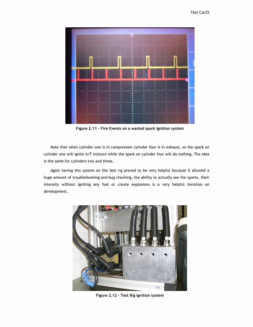
Figure 2.11 - Fire Events on a wasted spark ignition system
Note that when cylinder one is in compression cylinder four is in exhaust, so the spark on
cylinder one will ignite A/F mixture while the spark on cylinder four will do nothing. The idea
is the same for cylinders two and three.
Again having this system on the test rig proved to be very helpful because it allowed a
huge amount of troubleshooting and bug checking, the ability to actually see the sparks, their
intensity without igniting any fuel or create explosions is a very helpful iteration on
development.
Figure 2.12 - Test Rig Ignition system

26 Hardware and Set Up
The rig has four injectors similar to the ones in the car; the injectors are electro-
magnetic valves. It helps for the project to put the figure all together and check the
microprocessor outputs once the real parts have connected. It serves as a debug tool as the
injectors shall only be actuated when synchronization is achieved, so it serves as signal of lost
synchronization. In Figure 2.13 it’s visible the pulses to injector drives, one can see that there
is one impulse for each cam pipe that appears, again its shown that CAM signal is required to
know what stage the correspondent cylinder is in. Without CAM signal the controller wouldn’t
know if that position was the explosion or intake (both times piston is going down).The power
supply for the injectors is simulated by the fuel pump relay, which is non-existent in the test-
rig. In order to make the connection of all parts to and from the microprocessor there is a
connection box that replicates all the EMS-12 board numbered and a Control Area Network,
CAN, connection lead.
Figure 2.13 - Fuel Trigger(red) and Cam signal (yellow)

Test Car27
Figure 2.14 - Test Rig Connection Box
The first process was to write a piece of software that could read the sensors and indicate
FULL_SYNC as position status, this would indicate that the microprocessor is reading the
sensors correctly and the functions set-ups are correct. This process proved to be largely time
consuming.
The EMS12 base-board was designed on the early days of the company and wasn’t object
of new revisions creating some implications with the new MPC5566 top boards. So, the
company has documentation in order to make correspondence tables between MPC555 and
5566.

28 Hardware and Set Up
2.3 Test Car
Figure 2.15 - Test Car
For this project the company acquired a Volkswagen Golf GTI 2.0 with a petrol engine,
Figure 2.15.
Everything used is stock besides the ignition system. The car has electronic multi point
injection system with four injectors (one for each cylinder) injecting fuel once at every
engine revolution.
Throttle body system with a DC motor to idle speed control as well as Mass Air Flow
sensor, (MAF). MAF is a sensor of type “Hot-wire” it has an in-built heater that creates
current flow through a thin wire, and with the passage of air this wire will cool down,
changing the current across its terminals, this type of sensor is highly nonlinear, and without
the help of the manufacturer datasheet is virtually impossible to know exactly how to read
the data output. Coolant temperature sensor, CT and Air Inlet Temperature, AIT, are variable
resistors with temperature, their function is relatively straightforward, they work as a
potentiometer, or a voltage divider, from a voltage reference from microcontroller (5V), by
changing their electrical resistance with temperature the voltage drop across its terminals
will vary, and a temperature dependent on voltage may be extracted. VR/HF speed/position
sensors of the type used in the test rig, these are magnetic sensors that works by sensing
electromagnetic forces across the sensor, the magnetic field originates a current flow in the
sensor.
Test Car29
2.4 Set up
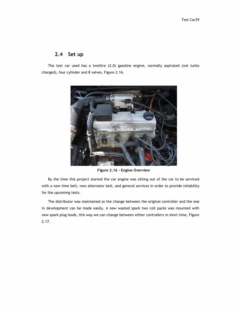
The test car used has a twolitre (2.0) gasoline engine, normally aspirated (not turbo
charged), four cylinder and 8 valves, Figure 2.16.
Figure 2.16 - Engine Overview
By the time this project started the car engine was sitting out of the car to be serviced
with a new time belt, new alternator belt, and general services in order to provide reliability
for the upcoming tests.
The distributor was maintained so the change between the original controller and the one
in development can be made easily. A new wasted spark two coil packs was mounted with
new spark plug leads, this way we can change between either controllers in short time, Figure
2.17.

30 Hardware and Set Up
Figure 2.17 - Coil Pack added with distributor in background
The only difference for the test rig, is the use the flywheel sensor as crank signal, this is
mounted on a 60-2 (50 physical teeth and 2 missing teeth)configuration and uses a HE sensor
type. The flywheel is mounted inside the engine case and it has a Hall Effect sensor as
position/speed measurement. First it was being used an external crank wheel with a VR
sensor, this toothed wheel is a 36-1 configuration, after some tests and problems identified
the decision was to use the Volkswagen standard flywheel (mounted inside engine case) which
proved reliable. The software is easily interchanged between the two configurations (36-1 or
60-2).
The process to start the car tests begun with the task to assemble the engine back into
the car, and make all the old connections so the car would run in it's normal state.This was
very helpful because after this process we can conclude that any problems that could appear
had to do with the newly introduced hardware/software.
After this verification was completed, the new task was to identify every wire from the
old controller, this turns into a complicated task since many wires in a car electrical scheme
are common or end up connected to ground (as the car chassis for instance).
A new harness was created that allows the interchange between the old and new
controller by just plug in/out as the wires were kept by the same order, Figure 2.5.
A multimeter and an oscilloscope were used to identify some of sensor signals and check
the continuity of thenew connections. This was a tedious job that required a lot of attentions,
since problems occurring from bad wirings are common but their source incredibly hard to
identify after everything is in place.
Several new wires had to be added, for the new ignition system, for example, so a
separate wire harness was created to keep the interchange ability between the two systems.

Set up31
This new harness now contains some power feeds direct from car’s battery ground
connections and the connections for the new O2 sensor lately bought. Figure 2.18, shows the
main specifications of the wideband 02 controller, this controller allows the output of a linear
0-5V output signal configurable, so the user can change the transfer function to allow
different performances or to fool the ECU (making the Original controller think it’s running
lean leading to an increase of fuel injected and more performance).
Figure 2.18 - O2 Sensor and main specifications
As we didn’t have sensor’s datasheets it was hard to know what throttle position matches
a certain voltage. So tests were made in order to map sensors transfer functions. Scope and
multimeterhelped to extract valuable data. This was done for TPS, MAF and all other sensors.
To map CT and AIT, an external thermometer was used with the help of boiling and
freezing water. This proved to be accurate enough for this experience.
Figure 2.19showsa cranking at a start attempt. We can see engine speed versus time. The
little “jumps” corresponds to compression of the cylinders that makes the starting motor slow
down. When the engine finally starts speed immediately rises. This was one of the first tests
made, and is why the crank time to the car start takes so long. The cranking speed is around
200-300rpm and after 1minute it increases to 800rpm (engine firing and running).

32 Hardware and Set Up
Figure 2.19 Crank Attempt

Chapter 3
Software Development Tools
This chapter describes the tools used for debugging and creation of the project's software.
Many of the programs listed here are widely common within the automotive industry. Some
other tools are suited for the same purpose, but these ones were available and fit the
purpose.
3.1 Lauterbach Debugger
Another important tool provided for the first problems trace in software was the
Lauterbach debugger.
With this debugger the user had the ability to check and change in real time the values of
configuration registers on the microprocessor, and therefore do a quick debug of the
software. In the first software versions that were built this was particularly useful as
configuration errors would cause the microprocessor to enter in restart mode, and it is
impossible to detect problems without running step by step and analysing the important
memory segments for flaws.
Some configurations of port bits and function assignments can be viewed using this
debugger.
34 Software Development Tools
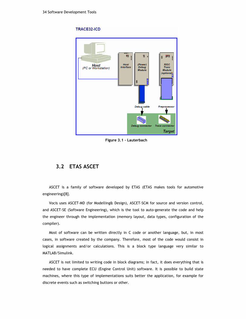
Figure 3.1 - Lauterbach
3.2 ETAS ASCET
ASCET is a family of software developed by ETAS (ETAS makes tools for automotive
engineering)[8].
Vocis uses ASCET-MD (for Modelling& Design), ASCET-SCM for source and version control,
and ASCET-SE (Software Engineering), which is the tool to auto-generate the code and help
the engineer through the implementation (memory layout, data types, configuration of the
compiler).
Most of software can be written directly in C code or another language, but, in most
cases, in software created by the company. Therefore, most of the code would consist in
logical assignments and/or calculations. This is a block type language very similar to
MATLAB/Simulink.
ASCET is not limited to writing code in block diagrams; in fact, it does everything that is
needed to have complete ECU (Engine Control Unit) software. It is possible to build state
machines, where this type of implementations suits better the application, for example for
discrete events such as switching buttons or other.
ETAS ASCET35
A real example would be the buttons to select what kind of traction mode you need
(Normal, winter, Sport, Track). ASCET also includes an experimental environment where code
can be tested in real time. Also known as a Software-in-the-Loop system (SiL).
The biggest feature of ASCET is the auto generation of the code. When writing software
for some automotive project, we have a lot of standards to respect. Those standards have
been established because of safety critical aspect of everything that is done on a car. Any
problem could cause a lot of trouble; even lead to the death of the driver. Anyone can
understand the importance of reliable software while doing 70 mph on the highway. Those
standards are called MISRA:C or MISRA:C++ (MISRA - Motor Industry Software Reliability
Association[13]).MIRSA was established in 1998 and updated in 2004 by a committee
composed of leading actors in the automotive industry.
When generating code with ASCET, you don't have to worry about all those standards as
they are automatically implemented and checked, and the programmer will know that the
standards are being respected.
One last important thing about ASCET is that when code is built, it provides an a2l file.
This file is the database of every variable, every constant, every signal present in the
software, with its address in memory and type of data. It is very important because it is
thanks to this file that we can easily communicate with the unit.
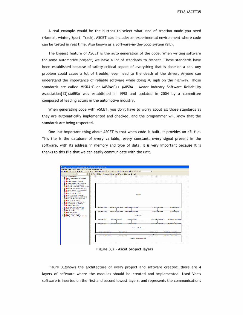
Figure 3.2 - Ascet project layers
Figure 3.2shows the architecture of every project and software created; there are 4
layers of software where the modules should be created and implemented. Used Vocis
software is inserted on the first and second lowest layers, and represents the communications

36 Software Development Tools
and raw data received through the sensor inputs and passed to digital values with the ADCs
converters.
The software created for this project consists mainly on the “interface layer” and
“algorithms layer”. The algorithms are the highest level layer and that’s where the control
methods and computational work is done.
Figure 3.3 - Ascet overview of project components and OS process
3.3 VECTOR CANape
CANape is software developed by Vector Informatik [6] a company created by three of the
people who create CAN protocol back at Bosch. When developing an ECU, or any other type of
controller, it is essential to be able to communicate with the unit. Even when the controller
is placed in the car, it has to communicate with other controllers, send messages to the
instrument board or with the on-board diagnostics computer. Together with the CAN protocol,
the XCP (CAN extended Calibration Protocol) is used to access all the calibration data of the
ECU. With this protocol, one can have access to every signal that is used in the software.
Basically, that is what the software CANape is doing. The signals to monitor are specified
in a list, then CANape is looking up this signal on the database to know at which address in
memory it needs to look, and then display the data to the user in a graphic or numeric form.

VECTOR CANape37
It’s a complete calibration and diagnostics tool.
On next figure it is visible a standard configuration page of what can be done with Vector
CANape. From the left hand side, it is visible the raw data read by the microprocessor, with
the centre correspondence to physical variables, after being calculated through transfers
functions within the software. On the right side there is some status variables with strings
which are called enumerations, this allows to pass numerical codes to words easily
identifiable by the user for instance one can read CRK_ENGPOSSEEK which states that engine
position is unknown to the microprocessor instead of the status code “0”.
Figure 3.4 - CANape set up to understand what is happening


Chapter 4
Microprocessor and Automotive Function Set
This chapter contains information related to microprocessors used on automotive industry
and their main characteristic. A brief description on some available functions for basics
commands in engine control is presented.
4.1 Microprocessor
Freescale semiconductors are a benchmark for the automotive industry, their
microprocessors are widely used in every branch of the industry and their reliability makes
the very demanding business sector trustworthy.The microprocessor, which on the actual days
is a true brain for the car used within this project, is the MPC5556 [2].
Freescale provides some function sets of preconfigured functions for use in automotive
industry (other sets are available for brushless DC motors for example). The various
application notes provided by Freescale were a precious help in understanding the function
set, and how to use it for this application.
4.2 ETPU Engine
The MPC5566 has several cores that deal with specific computational work, the main host
is what keeps everything alive, but for this type of application the most important core is the
enhanced Time Processor Unit (eTPU). Freescale provides a C-array compiled code that is
copied into the main host processor. Each function has a number that identifies it and the
channel assigned to each function will have the correspondent function number.

40 Microprocessor and Automotive Function Set
As described below, from the MPC566, these are the key features of an eTPU.
• Execute programs independently from the host core
• Detect and precisely record the timing of input events
• Generate complex output waveforms
• Enhances the CPU with time processing without requiring real-time host processing
The host core setup and service times for each input and output event are greatly
minimized. The eTPU improves the performance of the device by providing high-resolution
timing:
• eTPU dedicated channels include two match and two capture registers (TPUs had
one).
• eTPU engines are optimized to service channel hardware
• Fast instruction execution rate of the eTPU engine reduces service time
Because the response to hardware service requests is primarily done by the eTPU engine,
the host is free to handle higher level operations.
The eTPU is a real-time microprocessor subsystem. Therefore, it runs micro engine code
from instruction memory to handle specific events and accesses data memory (SDM) for
parameters, work data, and application state information. Events can originate from I/O
channels (due to pin transitions and/or time base matches), device core requests, or inter-
channel requests. Events that call for local eTPU processingactivate the micro engine by
issuing a service request. The service request microcode can send an interrupt to the device
core, but cannot directly interrupt the core using I/O channel events.
Each channel has a function that consists of a set of micro engine routines, called threads
that service eTPU requests, which define the channel’s behaviour. Function routines, which
reside in the SCM, are also used to configure the channel. A function can be assigned to
several channels, but a channel can only processes one function at a given moment. The eTPU
can change the function assigned to a channel if it is reconfigured by thedevice core.
The device core configures the function to channel assignments. The following eTPU
hardware supplies resource sharing features that support concurrency:

ETPU Position functions41
• A hardware scheduler dispatches the service request micro engine routines
based on a set of priorities defined by the device’s core. Each channel has its own unique
priority assignment that primarily depends on CPU assignment. The channel’s number is
an inherent property also used to determine priority.
• A service request routine cannot be interrupted by another service request
until it ends, that is, until an end instruction is executed. This sequence of uninterrupted
instruction execution is called a thread. The core can terminate the thread by writing 1 to
the FEND bit in the ETPU_ECR register.
• Channel-specific contexts (registers and flags) are automatically switched
between the end of a thread and the beginning of the next one.
• SDM arbitration, a dual-parameter coherency controller, and semaphores can
be used to ensure coherent access to eTPU data shared by both eTPU engines and the
device core.
4.3 eTPU Position (CRANK and CAM) functions
The position of a piston in an internal combustion engine is determined as an angular
position relative to Top Dead Centre (TDC). All the calculation regarding engine control to a
specific cylinder are made knowing its angular position. A piston moves in a linear straight
line, so it may cause some confusion the fact its position being measured in degrees.
This happens because the only way to know the actual position of a piston is to read the
movement of the crankshaft, which presents rotational movement therefore angular
variations, the crankshaft has a solid connection with the piston therefore have a direct
correspondence with the linear movement of a piston.
Each engine has a specific construction value, which relates the TDC of the cylinder
number 1 to a specific angular position of the crankshaft. This position will match another
well-known and specific position of the camshaft.
The microprocessor, and the automotive function set available from Freescale, have two
functions that work together in order to acquire and maintain a read of the engine position at
all time. CRANK function is responsible to read every tooth from the rotational crank
flywheel, and the CAM function detects and stores the angular position where the CAM pipe
appears.
CRANK function starts detecting the teeth and when a gap is recognized, it changes the
position of motor to HALF_SYNC, this means that crank position is known, engine control can

42 Microprocessor and Automotive Function Set
be made without major danger, but it is not advised since one can’t know if the engine is in
its first or second 360º turn.
Once CAM function detects camshaft position and informs CRANK function of its position,
the engine position changes to FULL_SYNC, from this moment on, the complete position and
cycle of every piston is known. For example, cylinder 1 is at explosion and escape at TDC, and
only with full synchronism between the two functions one can tell which time is which.
The both functions belong to the available function set at Freescale, and their result and
can be accessed by the function fs_etpu_eng_pos_get_engine_position_status().
In any moment if the synchronization is lost by any reason the status changes and the
software should be constantly reading this function to act accordingly if sync is lost.
This function (CRANK) supports two different crankshaft wheels, 36-1 or 60-2 which
indicates that the toothed wheel will have 35 or 58 physical teeth and one or two missing;
there are special layouts of some manufacturers that allow different control techniques for re
synchronization and other extra things that may be required.
Figure 4.1 - CRANK position wheel 36-1 configuration
The functionhas the ability to make gap tests in order to verify the position and
synchronization. There are a lot of initialization parameters to be careful with. This function
dictates the good behaviour of every other function used in this project. The function uses
previous tooth period and defined ratios to assure the gap has been found. These ratios are
very important and it was one of the initial problems to solve between the test rig and the
car.
On cranking, the engine speed changes every quarter of a revolution due to cylinder
compression. So, starting motor slows down and this can create problems if the compression
corresponds to the gap. To bypass these problems ratios must be specified. Ratios allow the

ETPU FUEL function43
software to distinguish from gaps between normal teeth, the gap and the first teeth and
tooth after the gap. They are used together with previous periods of detecting teeth, and
guarantees correct behaviour in accelerations and decelerations.
Figure 4.2 - Gap test
4.5 ETPU FUEL function
The application describes this as follows. The FUEL eTPU function generates one or more
fuel injection pulses and thus controls the amount of fuel in the intake manifold. Fuel
injection pulses start at a calculated engine cycle angle (0–720 degrees) based on a specified
end angle and the amount of fuel required. Multiple additional injection pulses are allowed.
Injection time for the last engine cycle (per cylinder) as well as the total injection time
over all cylinders is stored. The eTPU synchronization functions, CAM and CRANK, provide
angular information to the FUEL function.
Figure 4.2shows the behaviour of the fuel functionand the main parameters used to the
execution of an event for fuel injection into the intake manifold. This is the simpler form of
an injection pulse, and this is the form used through the application created.

44 Microprocessor and Automotive Function Set
Figure 4.2- Time diagram of a simple injection pulse
It’s possible to create more complex events for fuel injection. Thesemethods are used in
complex control systems for direct injection and air/fuel mixture stratification processes.
The FUEL function guarantees that no fuel is injected after the drop dead angle, which
corresponds to the angular position of closing the intake valves specified for that cylinder,
even if it’s requested more fuel. So while this angle is not met, the user can configure and
change injection times for different types of requests, for example for fuel economy and
efficiency.Figure 4.3 shows a direct injection event, with one pulse serving the wet wall stage
and multi pulses cause mixture stratification. Stratification occurs when the gasoline and air
are not completely mixed. This means that there are layers of air and layers of fuel. This
allows a better fuel efficiency since it allows for the combustion and explosion in poorer
mixtures producing the same torque.
Some systems even work to create geometry of fuel and air favourable to combustion
inside the cylinder chamber. The opening of intake valves and the direct fuel injection works
so the air flow creates space so the fuel sits closer to spark in order to make the ignition and
combustion easier.
Figure 4.3 - Complex fuel injection pulse

ETPU FUEL function45
The eTPU channelsassigned with this function are linked to the CRANK function by the
CRANK_LINK parameter; this allows the channels to be disabled in case an engine stall occurs.
This is important for safety reasons. This function is time based opposite to the Spark
function, which is angle based, please refer to the application note AN3770 for further detail
on how to use this function. There is the possibility to change in real time the specification
of each fuel event, but many of the parameters arefor initialization only and they must be
correctly specified such as cylinders offset angles and crank channel for position recognition.
4.6 ETPU SPARK function
The eTPU SPARK functioninitializes and controls the generation of spark pulses
synchronized to specific angular positions of a rotating engine, thus controlling ignition timing
of the engine. The function outputs one or more spark pulses during each complete engine
cycle without CPU intervention. The properties of these pulses are programmable, and update
functions allows for the pulse properties to be changed during runtime.
The SPARK function supports the generation of either one or two main spark pulses per
720° engine cycle, as well as optional multi spark pulse generation for ignition algorithms
that use spark multi-strike. Minimum and maximum dwell time enforcement, selectable
output polarity, and asynchronous updates are also provided.
Many parameters are crucial in order this function produces the desired results. For more
detail please check the application not AN3771 from Freescale for a full explanation on each
and every one of these parameters. The most important and easy to understand are explained
on the following figures. The min and max dwell times, guarantees that the coil charging
times are never smaller or greater and these values, in any case the programmer requests an
event outside these boundaries the time will be truncated to meet the limits.
The Recalculation offset angle is a derived parameter, this is because this function works
in angle based, so it has to calculate the angle when start charging the coil to give an event
at a specified angle, it has to use engine speed for this, and every event requires that the
start angle is derived accordingly to the engine speed and end angle. The control software
has no control on the position where the coils charge starts, it only specifies the dwell time
and spark angle, the eTPU SPARK function is responsible to every engine cycle determine the
exact position of start angle in order to guarantee the parameters specified.

46 Microprocessor and Automotive Function Set
Figure 4.4– Spark Event
The link with CRANK link provides the information about acceleration and deceleration by
means of a counter set to a high frequency and records counts per tooth, the changes in this
variable indicates if the speed increases or decreases.

ETPU SPARK function 47


Chapter 5
Implementation
The process of software creation is dealt with in this chapter. The constraints concerning
software development for safety critical applications are explained. All the algorithms
created specifically for this application are described.
5.1 Software Requirements
The first software for the controller was written in C-code and served to test the
operation of eTPU functions. Most part of initial steps consisted in understanding and being
able to correctly operate the eTPU function set from Freescale for automotive applications.
Vocis created a large part of the initial software needed to use on this project:
configuration of microcontroller base registers, input/output ports, ADC sampling and
conversion rates and values where configured from previous projects and are property of
Vocis, Ltd.
This is possible due to the database type of content used in ASCETModules are created
separately so they can be exported and reused. The company owns a MKS server to keep
records and history version of all software created inside the company. For security and
confidentiality reasons students can’t access to this server, so it’s impossible to change any of
the software created by employees, but every module needed was provided in an offline
environment.
The EMS-12 was design to use a top board with the MPC555 microprocessor, but with the
migration to the MPC5566, some problems arise. Main connections had to be kept in place but
some ports and channels are interchanged with this microprocessor. For that an excel file
containing corresponding channels from the 555 to the 5566was provided. With this it was
possible to start configuring the channels needed to correctly configure the MPC5566.

50 Implementation
From the initial configuration some changes had to be done in the SIU configuration. This
part of microprocessor is responsible for defining the task for every pin. The
Lauterbachdebugger was a precious help on this matter since we can see bits value at register
levels, so it’s easy to spot errors and miss configurations.
In order for the company to comply with standards for software creation for automotive
industry, many rules were to be learnt by persistent failures. For an inexperienced software
writer many of the rules seem dull and meaningless, but as the same inexperienced software
developer may learn they were very useful in the future.
As described the software is written in modules, so it can be easily understood and
complex programs easily read. There is an imposition that every variable created within a
module has a three letters prefix stating the module where it was created. For example
IOP_EngineLoad,is created on the module IOP and although is used in many parts of the
software this indicates that if anyone wants to see anything related to this variable should go
to that block.
There are several types of data in a program; the most common in this software are
variables and parameters. Another important rule is the naming of these two different types
of data. Every variable has the prefix and then is written as a normal word or set of words
together (IOP_EngineLoad), while the parameters are compulsory written in capital letters
like THR_THROTTLEIGAIN. This is very important in large and complex programs, since in the
development chain there are people writing software and other people doing the calibration
(controller gains, maps, transfer functions) so to avoid mistakes a code name is used so
anyone can easily identify what type of data is dealing with.
Other thing is the implementation definition. ASCET works with physical values, and all
the values represented are physical measures (for example time, temperature and so on). In
order to have enough resolution normally an implementation is created where the writer
gives the order to ASCET to use values greater than the physical ones so the computational
work is done with more resolution. Is another mandatory rule for developed software that
every single variable, parameter and table is implemented with meaningful values and an
acceptable resolution.
In many cases the compiler accepts and warns that the resolution will be changed to fin in
variable range.The software writer should pay attention to this and make modifications and
accordingly.
There are a lot of rules to which to comply.The listed above are just a small idea of the
kind of things that may seem pointless but are very important in safety critical applications
Figure 5.1 shows a formula-editing that will be used to give resolution to the
InjectTimeRatio variable. This allows the time of the last injection to be presented in

Fuel Pump Module51
milliseconds with microsecond resolution. CPU frequency is 16MHz so you need to multiply it
by 16000 to have milliseconds. In the background some other formulas used within the
project are visible.
Figure 5.1–Formula edit in ASCET
5.2 Fuel Pump Module
The fuel pump is responsible for providing fuel rail pressure, so when the injectors open
fuel is injected into intake manifold. The fuel pump should not be ON permanently for
obvious reasons, such as overheating, battery consumptions, and safety reasons with fuel
pressure.
The normal procedure in this case is to turn the fuel pump ON only when it’s needed, and
turn it off 2seconds after it stops being needed. This allows that for a really quick stop in fuel
demanding the fuel pump is not off; the state diagram of the fuel pump is described in Figure
5.2.
Figure 5.3represents the module created in ASCET to make this control.If engine speed is
greater than 0 or if the engine position status is different than POSITION_SEEK (which has the
code 0) then the fuel is ON.

52 Implementation
Figure 5.2 - Fuel Pump State Diagram
The message FUL_FuelPump is the output and is a logical variable. Whenever
FUL_PumpRelayTime is greater than 0, the fuel is ON.
If those two conditions are not verified, the timer will be decremented until 0; otherwise
it keeps being fed with a static value, which will maintain the pump ON.
The output will drive the fuel pump relay in the relay box of the car; this relay is a low
side drive. Notice the sequence calls, the output is the last task done in this process (you can
see on bottom of the left hand pane the processes names) and this process is added to the
10ms task in the microprocessor’s operating system.
Notice the variable names and parameters follow the rules imposed inside the company
for software writing, all variables as a prefix that corresponds to the module they belong to
and the parameters (that can be changed in real time by CANape) are always capital letters.

IOP Module53
Figure 5.3 - Fuel Pump Relay Control
5.3 IOP Module
IOP module represents the input output processing module. In this module raw data is
acquired in terms of voltage and the data treatment takes place in order to give a meaning to
those values. The software in ASCET and within the company (and generally in the automotive
industry) is processed in physical values. For example, a variable resistance measuring the
coolant temperature gives an output of 0-5V but in the software that has to correspond to -45
to 130 degrees.
In this module values from analogue to digital converters (ADC) are treated and passed to
meaningful physical values. So, software from this point on makes more sense and it’s easy to
follow.
Analogue inputs received from ADCs modules (which turn the voltage into digital values)
passes through a specific transfer function so the output is a physical variable.
For example Analogueinput13 turns into Throttle Position percentage due to the transfer
function created. As explained before this represents physical meanings, in which case is
throttle percentage. The implementation gives a resolution of 0.01%. The example of this
transfer function is shown on figure X.XX. All analogue variables are processed similarly.
The voltage values between are calculated through linear interpolation, this is the easiest
way and most understandable one of calculation intermediate points.
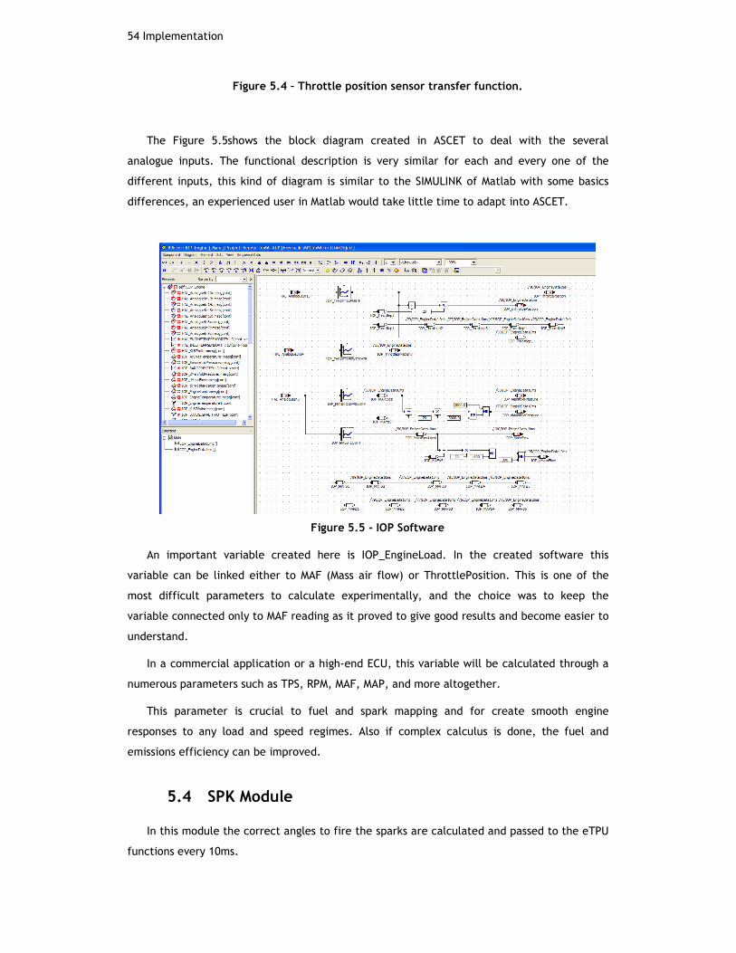
54 Implementation
Figure 5.4 – Throttle position sensor transfer function.
The Figure 5.5shows the block diagram created in ASCET to deal with the several
analogue inputs. The functional description is very similar for each and every one of the
different inputs, this kind of diagram is similar to the SIMULINK of Matlab with some basics
differences, an experienced user in Matlab would take little time to adapt into ASCET.
Figure 5.5 - IOP Software
An important variable created here is IOP_EngineLoad. In the created software this
variable can be linked either to MAF (Mass air flow) or ThrottlePosition. This is one of the
most difficult parameters to calculate experimentally, and the choice was to keep the
variable connected only to MAF reading as it proved to give good results and become easier to
understand.
In a commercial application or a high-end ECU, this variable will be calculated through a
numerous parameters such as TPS, RPM, MAF, MAP, and more altogether.
This parameter is crucial to fuel and spark mapping and for create smooth engine
responses to any load and speed regimes. Also if complex calculus is done, the fuel and
emissions efficiency can be improved.
5.4 SPK Module
In this module the correct angles to fire the sparks are calculated and passed to the eTPU
functions every 10ms.
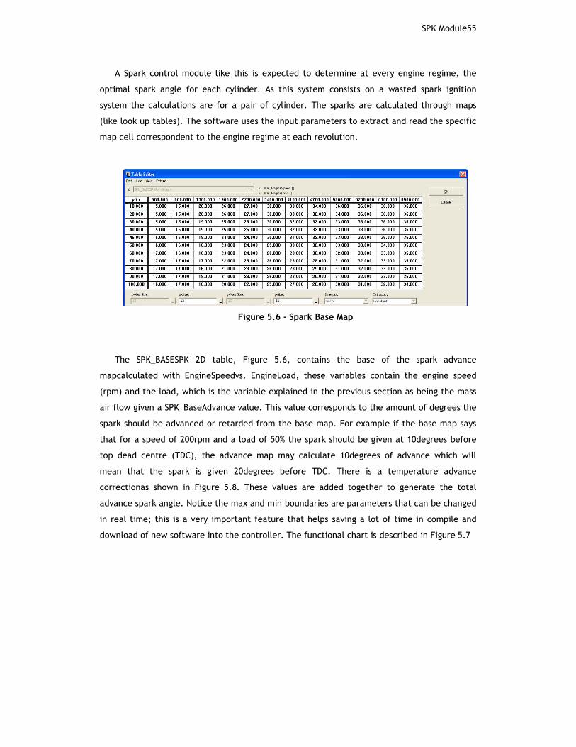
SPK Module55
A Spark control module like this is expected to determine at every engine regime, the
optimal spark angle for each cylinder. As this system consists on a wasted spark ignition
system the calculations are for a pair of cylinder. The sparks are calculated through maps
(like look up tables). The software uses the input parameters to extract and read the specific
map cell correspondent to the engine regime at each revolution.
Figure 5.6 - Spark Base Map
The SPK_BASESPK 2D table, Figure 5.6, contains the base of the spark advance
mapcalculated with EngineSpeedvs. EngineLoad, these variables contain the engine speed
(rpm) and the load, which is the variable explained in the previous section as being the mass
air flow given a SPK_BaseAdvance value. This value corresponds to the amount of degrees the
spark should be advanced or retarded from the base map. For example if the base map says
that for a speed of 200rpm and a load of 50% the spark should be given at 10degrees before
top dead centre (TDC), the advance map may calculate 10degrees of advance which will
mean that the spark is given 20degrees before TDC. There is a temperature advance
correctionas shown in Figure 5.8. These values are added together to generate the total
advance spark angle. Notice the max and min boundaries are parameters that can be changed
in real time; this is a very important feature that helps saving a lot of time in compile and
download of new software into the controller. The functional chart is described in Figure 5.7
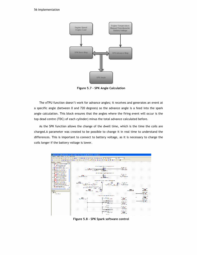
56 Implementation
Figure 5.7 - SPK Angle Calculation
The eTPU function doesn’t work for advance angles; it receives and generates an event at
a specific angle (between 0 and 720 degrees) so the advance angle is a feed into the spark
angle calculation. This block ensures that the angles where the firing event will occur is the
top dead centre (TDC) of each cylinder) minus the total advance calculated before.
As the SPK function allows the change of the dwell time, which is the time the coils are
charged.A parameter was created to be possible to change it in real time to understand the
differences. This is important to connect to battery voltage, as it is necessary to charge the
coils longer if the battery voltage is lower.
Figure 5.8 - SPK Spark software control

SPK Module57
The values are passed to the C-function module to update the values into the eTPU as its
shown in the next figure, SPARK1_SPARK4 and SPARK2_SPARK3 are the corresponding eTPU
channels for cylinders pairs, the code guarantees that cylinder 1 receives an angle lower than
cylinder 4.
Figure 5.9 - Spark angles load into SPARK function
5.5 Throttle
This module was created to control the idle speed by moving the throttle blade. The
throttle body has a small DC motor that has the availability to open slightly the air blade
allowing air into the intake manifold and therefore control the engine speed. This motor is
controlled by an H-Bridge included in the EMS12 board, the microprocessor has to define the
PWM frequency and H-bridge direction and then update the duty cycle wanted to keep the
blade at a certain point.

58 Implementation
Figure 5.10 - Throttle Duty Cycle control
The strategy consists in the creation of two loop or stages PI controllers running at
different speeds.
The inner loop is responsible for providing position control, and its output is the direct
duty cycle for the H-Bridge.The error for this PI controller is then the difference between the
actual position measured and the position that we want the throttle.
By the following figure we can see that a feed forward stage was added to the PI
controller. This allows a certain amount of prediction as the feedforward indicates what the
duty cycle should be for that request. This is calibrated by experimental data and test and
error tries.
One of the differences you may spot from the diagram to the traditionally PI schematics is
the inclusion of some “funny blocks” in the controller. These blocks create a Dither Filter,
very used in dynamic of moving objects.
The main goal of this filter is to guarantee vibration at a certain frequency even when the
throttle is stopped. This allowsfor rapid position demands occurences with less overshoot.If a
mechanical part is stopped you need to create a force just to oppose its inertia to put it in
motion.
This filter tries to reduce that amount so when you apply a force is just to position the
blade not overshooting position, which may be dangerous in vehicle operation.
On Figure 5.11its visible the creation of the modulated wave, THR_DithCtr will be
incremented until reaches THR_DITHMAX (again this is full capital letters indicating that is a

Throttle59
parameter) and then reset. The counter increments one unit every 1ms so with the parameter
we can easily change the frequency of the modulated wave
Figure 5.11 – Dither filter
This block, after some parameters tuning proved to be very accurate and the inclusion of
the anti-windup blocks helped to the rapid response of the controller.
On the first tests made only this block was implemented in the car and it allowed us to
hold the throttle at a specified position without having to press the foot against the pedal.
This block is linked to the process, which is included in 1ms task, so the update for the
PWM will occur every 1ms.
The outer loop for this controller consists on a speed based PI controller.This stage is
responsible for maintain a speed reference as idle speed demand, and create position demand
for the inner loop. The error for this will be the difference between the speed demand and
the engine speed measured.
Once again a feed forward stage was included to provide some kind of prediction on what
is the best position for a certain speed demand.
The following figure demonstrate the outer loop created, its visible the P term I term and
FEEDFORWARD term being added together, the output limited is a requirement for software
writing and ASCET and there is a possibility to turn this off for test purposes. The I term is
cramped with anti-windup terms that states that at any time its value is greater than the
inverse of the P term.

60 Implementation
Figure 5.12– Throttle control for idle speed
5.6 Fuel Control
This module was subject most time consuming and the focus of most. In the beginning
there were only the blocks to determine the pulse without any type of variability or changes.
With the software evolution and system comprehension, more control techniques were
sequentially added until the fuel map became fully automated with base maps and
enrichment strategies.
Figure 5.13 - FUEL Total Time Calculation
To explain this module it's better to divide it into parts. There is the base map, the
enrichments calculations and the O2 control. Monitoring all this there is the shutdown
controllers and some overrun fuel cut off.

Fuel Control61
The base fuel map was created mapping the Engine Speed against engine load. This is
usually common in all applications; the difference sits in how to calculate the engine load
variable. Next to the engine base map, it’s multiplied the FUL_GammaEnrich which is a
percentage variable that’s multiplied to the base fuel map and will increase the total amount
of fuel injected this variable contains the sum of the FUL_AccelEnrich ,FUL_AfterStartEnrich
and FUL_TempEnrich. These enrichments are correspondent to acceleration, after cranking
and temperature enrichment. After this we have an addition of fuel that refers as
FUL_CrankEnrich, this is the cranking enrichments (when the car is starting with help of the
start motor) and is added in milliseconds that’s the reason why is not contained in gamma
enrichments.
Next figure shows the complete code created to calculate fuel injected from base map
plus enrichments. Notice that it is possible to turn the enrichments off (less the CrankEnrich)
using the parameter FUL_ENRICHMENTSONOFF.
Figure 5.14 - Fuel Pulse width calculation
Figure 5.15 - Fuel base map
On the following figure is showed the blocks created to make the enrichments, one extra
thing is the enrichments created by IOP_PotGamaEnrich this was a late addition and basically

62 Implementation
a potentiometer was inserted into the car’s central console so the driver can add or remove
fuel for test purposes, this is clamped to more or less 50% fuel at any time, and a gain is
optional to reduce that amount.
The variable FUL_TimeSinceCrank was also created and is a timer that starts to count
every time that engine speed is different from zero. In order to turn the crank enrichments
off, the speed is compared to a parameter defined Crank speed and once it’s over the crank
enrichment is zero
Figure 5.16 - Fuel
The are some extra rules created for fuel module, one thing that is normally done, is to
do an open loop fuel injection (when using closed loop with lambda sensor) when the car is
accelerating and requires more fuel, this normally makes the car actuate outside the
recommended AFR region so having the sensor close loop would stop this to happen.

Fuel Control63
Figure 5.17 - Open Loop fuel rules
Another rule is the fuel cut off with overrun. Overrun is achieved when the driver isn’t
pressing the pedal but the car is still with high rpm, in this case the fuel map will continue to
order injection of fuel when not need, so an over run cut off is implemented in order to stop
the fuel injection.
Figure 5.18 - Fuel Overrun
All these rules come together to calculate the final injection time passed to the eTPU
function. One can see on next figure that the rules explained before turn the total injection
time in zero.

64 Implementation
Figure 5.19 - Fuel time output
One last fuel rule created was the rev limiter, this piece of code limits the rpm by cutting
fuel after a user defined rpm limit, and there’s a hysteresis window created so the fuel will
be re activated after the rpm drops to the defined speed.
Figure 5.20 - Fuel limiting rpm
With the amount of tests made with fuel eventually the exhaust and spark plugs gets with
too much fuel, so a part of software was created to clean it ordering the engine to fire sparks
and getting air into the exhaust by shutting the fuel off. This was called FUL_FloodClear and
as it is presented on next figure, if the engine speed if lower than 550rpm and the driver is
with is foot on the pedal over 70% then it will created a condition to put the injection time to
0 and cut the fuel.
Figure 5.21 - Fuel flood clear

Fuel Control65
A techedge 2J1 wideband lambda sensor was acquired to make a closed loop fuel control
process. The wideband lambda sensor allows the user to read all the scale of the AFR while a
narrow band sensor usually just indicates if the mixture is rich or lean.
The close loop is used to try to maintain the mixture at 14.7, which represents lambda 1.

66 Implementation

Chapter 6
Tests
“The 0 errors 0 warning the compiler gives don’t mean the software is right. It is right
only when it does what you want.”
Along the project, as stated in previous chapters the software created was constantly
validated by tests either in the real car or on the test rig. All the rules for create software
that company uses were followed so the safety of the application is maintained. The company
is certified for writing software for the automotive industry, this states the quality level and
the commitment they put into their applications. It proves reliability,which is demanded by
company’s clients.
The tests made include the validation of software by the ASCET compiler, the
implementation errors and warnings must be corrected, as it’s not allowed to download
software with any type of fault into the controller.
The correct behaviour of the software was checked and verified on the test rig when
possible and after checked on the real car. On the early stages the results were considerably
different on two systems mainly due to wiring faults.
The most time consuming and that can frustrate anyone doing such a job is to write
software, test it on the rig and not working on the car, this many times conducts to nearly
despaired states. It is very recommended that people take their time to make up the wiring
and wire “guessing” as this proved to be very painful in future stages.
The car tests consisted mainly in idle the car on the car park, this was done to prove all
the functions were working accordingly to expected, the synchronism wasn’t lost and the
firing events were occurring at correct times, some problems with floating grounds and
misfires where found during this process. The wire used to bring the signal from the VR sensor

68 Tests
to the EMS-12 was unshielded and their proximity to the spark plug leads (where high current
flows) the sensor signal was simply suppressed by the noise created. This was solved by using
the HE sensor in the engine flywheel, which has a much higher signal to noise rejection
allowing the correct reading from the controller.
After this being achieved, the fuel maps started to be the focus of the tests. First the
start enrichments were the problem since every morning with the cold car the car struggled a
lot to start the first time. Some experiments dictated the amount of enrichment in order the
car started fairly quick, once this was accomplished, it was time for a few runs around the
compound to check load variations and fuel injection, first attempts conducted to very
wobbling rides around the car park, but with the CANape help and changing in real time the
fuel amount it got smoother.
Finally the car went into the track for more demanding tests, and for more fuel mapping,
after a while the tuning was allowing good performance in almost every region of the map
(Load vs. rpm) and it achieved a top speed of nearly 200 Km/h on track.

Chapter 7
Results
With this chapter I will try to present the obtained results with the implemented software
explained on the implementation chapter.
A small video was created to show the test rig working. In this video it’s possible to
hear the injectors working and sparks are visible in the spark box of the test rig. As the
project ended prematurely it wasn’t possible to book the track for video footage with the car
running with EMS-12 controller, but the principles are the same as the test rig. To view the
video please visit http://www.flickr.com/photos/whynot_uk/4668762704/ .
The list of results presented tries to prove the project works and does what is supposed
to. Many oscillograms and figures could be added but these ones are intended to resume the
project in a fair way.
The prohibition on cameras usage within MIRA’s proving ground makes the process more
difficult.
The results obtained where very satisfactory and proved all the implementation and
software. The test rig oscilloscope reading showed the correct behaviour of every parameter
important for the project.
WithFigure 7.1, it is possible to see the variables of synchronism and shows that the
software is working, reading and presenting all the values needed to know the position and
speed of the engine.

70 Results
Figure 7.1 - Engine Position Status
With the following figure, it is possible to see the variation of the fuel injection time
coming for the base fuel map (without enrichments or corrections) with the engine load. With
help of CANape software, it is easily visible that the software is changing the amount of fuel
accordingly to the load at every moment; this allows understanding and debugging this part of
software showing that the engine load is being read and calculated and it’s correctly linked to
the fuel map.
Figure 7.2 – Fuel injection variable with load
The next figure intends to show the configuration in CANape where it’s visible the spark
angles; one can see that cylinders 1&3 and 2&4 have the same absolute angle. This is because
the system used is wasted spark, so each cylinder receives two sparks in each engine cycle.
To make the debug easily, the variable speed and load are also visible in the same page.
Figure 7.3– Spark Angles in CANape

71
Figure 7.4 - Visible Sparks in Test Rig
WithFigure 7.5, it’s visible the control of the fuel map by the O2 sensor feedback, in the
pink line its visible the reading from the O2 sensor and the white line is the injection time of
the injectors. The PI controller is not calibrated, butone can see that when the pink line
rises, meaning a lean (lack of fuel or too much air) mixture, the amount of fuel (yellow line)
increases.
This tries to follow a reference of an A/F equal to14.7, which is the stoichiometry for
gasoline engines.
Figure 7.5 – Fuel O2 Sensor and Fuel Inject Time

72 Results

Future Work
As stated in the early chapters of the document, the possibilities are almost endless, and
nowadays the amount of work and complexity of an ECU is extremely high. This document
presents the low level configuration and early staged of software development for the
creation of a working ECU.
The following work would consist in inserting a wideband O2 sensor, which probably would
require the change of the complete exhaust system since the actual one is much damaged.
With this it would be possible to tune the car for stoicometric mixture, which would leadto
better performance and lower emissions for the car.
The use of knock sensor would be something to look into very soon since the maximum
advance of the spark timing produces more power and torque from the engine. And constant
knock of the engine may produce irreparable damages to it.
Th inclusion of a full electronic throttle body system into the car was discussed.This part
is stock in many cars and belongs to the drive by wire parts.With this part a better idle speed
control and a torque demand with the throttle pedal could be achieved.
Nowadays the level of computer calculations is so demanding that the workforce is
distributed among several small ECU, for example the abs systems, ESP and differential
control (when car is provided with electronic active differentials) have their own dedicated
control modules. Ultimately the main ECU can control these separate modules and provide a
safety check and act in emergency scenarios.
This type of car only has abs system asthe listed above and it could be one next step to
take into account
The tuning of fuel and spark maps can go indefinitely, and several set-ups for
different applications can be created.For example the ECU may have the possibility to change
between sport and economic configurations that totally change the fuel and spark maps.

74 Future Work
As described before the EMS12 is prepared for an engine with up to 12cylinders and this
project used just a part of its capabilities, so one of future works could be the creation of
generalized software for different type of engines. The configurations set-ups can be easily
interchanged in boot definitions.
These are just a few ideas on where to go next, since there are a lot that can be
achieved. The current status of the project is a good starting point for the application of any
of the future projects.

Conclusions
As referred along this document, the product presented doesn’t have the time of
development of the systems on the market; at this point it doesn’t constitute a valid
alternative. But instead, it shows the potential to become a very valid and serious product in
this sector. The hardware is very high standard, and the software needs moredevelopment to
reach the actual standards.
Analysing the actual state of the project, one can say that the main goals were achieved,
many other things could have been done as stated in previous section, but due to the early
ending of the project it is fair to consider that the project is more than satisfactory.
Initially the idea was to spend 8 months developing an ECU so it would be a competitive
product among the rivals, but with company’s business strategy and negotiation it has been
decided that this product establishes the basis for the build of an ECU and the algorithms and
high level software should be left to possible clients of this product.
The subjects presented in this project were of particular interest and some previous
knowledge of the electronics and mechanical automotive was present, completed with the
class Automotive Electronics at faculty.
This project tests a wide range of knowledge simultaneously; many areas of the degree
are tested, such as electronic knowledge in measuring, connecting, and acquisition signals
from sensor. Soldering and PCB design interpretation were part of the project. The
microprocessor coding and functioning are an extent to the subjects learnt in faculty.
The company is pleased with the actual status of the product, and they already studied
some modifications to do on the board if they release a new version of it.
In my perspective I couldn’t ask for a more motivating final project to finish my studies,
I’ve always loved the automotive industry so for me this is quite an achievement to be able to
work with such experienced people in the business. The company’s atmosphere is very
friendly, mainly because it is a small company where everybody knows each other and great
inter help spirit and atmosphere is installed.


References
[1] Vocis Driveline Controls http://www.vocis.co.uk/
[2] Freescale MPC555 Reference Page
http://www.freescale.com/webapp/sps/site/prod_summary.jsp?code=MPC555
[3] FreescaleMPC554Reference
Pagehttp://www.freescale.com/webapp/sps/site/prod_summary.jsp?code=MPC5554
[4] Oerlikon Group homepage http://www.oerlikon.com/
[5] Nikolaus Otto http://www.yourdictionary.com/biography/nikolaus-otto
[6] Karl Benz http://www.britannica.com/EBchecked/topic/61255/Karl-Benz
[7] VECTOR CANape softwarehttp://www.vector.com/vi_canape_en.html
[8] ETAS ASCET http://www.etas.com/en/products/ascet_software_products.php
[9] http://www.mira.co.uk
[10] Understanding Automotive Electronics - William B. Ribbens, Ph.D]
[11] http://www.boschmotorsport.de/content/language2/html/2953.htm].
[12] http://www.megamanual.com/index.html
[13] MISRA organization homepage http://www.misra.org.uk/
[14] Ebook with automotive electronics information
http://www.tpub.com/content/construction/14273/index.htm