Embed Size (px)
Citation preview

Unit 5S , Lanvale Estate, St. Columb Major Ind. Est, CORNWALL, TR9 6SF Telephone: 01637 881520
http://www.ukcnc.net
Software Manual for the
Coil Winding Arm
Controller MKII Software. Version 1.1 31st October 2020.
This documentation applies for use of the software on the following machines:
• CNC 200mm Coil Winder MK4 fitted with ARM Controller MKII
• CNC 200mm Coil Winder MK5 fitted with ARM Controller MKII
• Mini Coil Winder MK4 fitted with ARM Controller MKII
• Quad Winder MK1 fitted with ARM Controller MKII
• Custom Coil Winders fitted with ARM Controller MKII

2 | P a g e http://www.ukcnc.net
Running more than one machine
This feature has been Implemented in CNC ARM Controller MKII Software Version 2.4 and
above.
Over the years we have been asked if it is possible to run more than one Coil Winding
Machine on a single computer.
The answer has always been NO, but after a bit of playing around we have released a new
Test version for anyone that has more than one machine and would like to try.
As stated this is a TEST and we do not guarantee performance like you would get with a
dedicated computer for each machine.
The Coil Winding Machines we supply all have the same USB VID/PID identification and this
will need to be changed on the extra machines that you want to run. This can be done by
programming up a different version of the firmware for each machine and also installing a
version of the software that will launch multiple sessions.
Here is a list showing which machine should have which firmware programmed into it.
Machine 1
ARM-CW-Firmware-MKII-2-0-M1.hex
Machine 2
ARM-CW-Firmware-MKII-2-0-M2.hex
Machine 3
ARM-CW-Firmware-MKII-2-0-M3.hex
You will need to use the JTAG programmer that was supplied with the machine to update
your Coil Winding machines and the instructions can be download below
Mini Coil Winder instructions:
http://www.ukcnc.net/CNC-mini-coil-winder-upgrade-firmwareV1-0.pdf
200mm Coil Winder instructions:
http://www.ukcnc.net/CNC-200mm-coil-winder-upgrade-firmwareV1-0.pdf

3 | P a g e http://www.ukcnc.net
When the software is first launched it will come up with the menu below:
So if we chose to launch three machines then it would launch 3 instances of the software
and show on each screen which machine it is connected to.

5 | P a g e http://www.ukcnc.net
Another change we have made is to disable the auto detect of the machine when it is first
plugged in and now you will be presented with another menu asking what machine you are
using:
If you have fitted a limit switch on the Mini Coil Winder or the 200mm Coil Winder MK4
then you can tick the checkbox for this option, rather than using the Custom Coil Winder
configuration.
If you select the Remember selection checkbox then this menu will not be shown again on
startup, but can be accessed within the software under the Settings/Diagnostics tab.

6 | P a g e http://www.ukcnc.net
Table of Contents
Automated Coil Winding - Tab. ........................................................................................... 7
Standard Script Engine – Tab ............................................................................................ 30
Absolute Scripting Mode – Tab ......................................................................................... 47
Manual Winding Mode – Tab ............................................................................................ 54
Settings/Diagnostics – Tab ................................................................................................ 56
Keyboard Mapping – Tab .................................................................................................. 62
Upgrading the Firmware. .................................................................................................. 63

7 | P a g e http://www.ukcnc.net
Automated Coil Winding - Tab. This tab shows a simple wizard which only needs a few basic settings to be made and you
will be up and winding your coil in the quickest time.
For a quick start you only have to set four parameters in the Automated Coil Winding tab
to wind a coil.
Set the Bobbin Width, Set the Total Windings, Set the Wire Size and Set the Desired Speed.
Then simply click the Start Button.
The software will then Wind the coil back and forth until the coil is complete.
Below we will go through each option panel and detail what they are.

8 | P a g e http://www.ukcnc.net
The Convert awg>mm will take the value entered in the box and convert from awg to
millimetres. This is a handy tool for people used to dealing with awg wire sizes.
In the example above it has converted 22awg, which calculates to be 0.6438mm.
The Switch to Pickups button changes the screen from normal bobbins to the Guitar Pickup
screen. This will be covered later on in the manual.
The TPL Calculator button will bring up a calculator panel on the screen. This will be
covered later on in the manual.
The Tension Calculator button will bring up a calculator panel on the screen. This will be
covered later on in the manual.
Next, with three simple steps you can setup the software to wind your desired coil.
1.) Enter the width of your bobbin is the actual length of the bobbin you wish to wind
wire across.
2.) Enter Total Windings for the coil you wish to make.
3.) Enter the wire Size you wish to wind but also allow for the coating. Typically, this can
be 10%-15% of the size of the wire.
After you have set these parameters, then the software will auto calculate the nearest
settings that are suitable for the machine you have connected and will display them in
the Status and Calculations panel.

9 | P a g e http://www.ukcnc.net
Based on the parameters entered in the Bobbin Dimensions panel, the actual working
values that get sent to the Coil Winding Machine are displayed in the Status and
Calculations panel. These calculations take into consideration the machine that is
connected to your computer and also the resolution settings applied.
In the example above, it has taken the parameters and calculated that the 16 winds will be
wound each layer and based on the width of wire, this would make the actual winding area
of wire cover 10.32mm and not the 10mm specified.
On the back of these calculations, it has also calculated that 31.25 layers will be wound
onto the bobbin. This is 16 winds to the right for the first layer and then 16 winds to the left
for the second layer and so on until the total windings are complete.
Now if your bobbin width is 10mm maximum then you will need to reduce the bobbin size
to reduce the windings per layer. The simple fact is that 10mm will not divide by the width
of your wire 10mm/0.6438=15.53 unless you are going to chop your wire in half at the end
of each layer, which is not possible!
In the screenshot below, you can see by reducing the Bobbin Width to 9.99mm it has
reduced the layers to 15 and also the bobbin width to 9.675mm. Not ideal as you may get
spacing created between each winding, which leads to uneven windings as your layers build
up.
The ideal bobbin would be the correct width to allow the exact number of windings you
require using the wire you need to use. But this is not always possible.

10 | P a g e http://www.ukcnc.net
We also have some status display objects in this panel.
Reply is the answer coming back from the Coil Winding Machine after each command is
sent.
Hardware Status shows of the Coil Winding Machine is connected or not connected to the
computer.
Bobbin Name Loaded is the name of the bobbin that has been chosen from the drop-down
box in the Load/Save Bobbin panel below.
As you can see all of the objects in this panel are for information purposes only and cannot
be set by the person using the software.

11 | P a g e http://www.ukcnc.net
The Load/Save Bobbin panel not only allows you to save and remove bobbin parameters,
but also lets you set other parameters that will affect the coil you are winding. These
settings, along with other settings from other panels get saved to the computer’s registry,
which can be backed up and reloaded in the future. This is usually due to either moving the
software to a new machine and wanting to bring your saved bobbins across to it, or in case
of a failure.
Starting from the top of the panel and working downwards we first have the drop-down
box. This will allow you to choose previously saved bobbin configurations.
When clicking the Save button it will ask for a name that you wish to call the bobbin and
save all the parameters set for that bobbin to the registry. If you wish to remove the saved
bobbin from the registry, then click the Remove button and it will delete that bobbin.
The yellow box below the drop-down box is for any notes you wish to save against that
bobbin. These notes will be saved along with other parameters and recalled when a bobbin
is selected.

12 | P a g e http://www.ukcnc.net
Wire Direction group box.
Sets the direction for the feeder arm when winding starts.
Bobbin Direction group box.
Sets the direction for the bobbin when winding starts.
Ramping Configuration group box.
We use stepper motors on our machines then to get them to higher speeds we need to
ramp up the motor speed gradually.
You have two variables you can set to get the desired curve as such.
The Steps variable is the divider of the target frequency that we want the bobbin motor to
run at. So, if the software calculated that the bobbin motor should run at 1000kHz and the
steps box is set to 100 then we can see that the steps would be 1000/100 = 10 Hz
increments.
The Pause variable is the time between each increment.
Ramping each layer checkbox.
If this box is left unchecked then the machine will ramp up at the beginning of the winding
routine and at the end only. When the feeder gets to the end of the layer it will simply
change direction. If the box is checked then the bobbin motor and feeder motor will ramp
up at the start of each later and ramp down at the end of each layer.
Pause at the end each Layer checkbox.
Checking this box will pause the machine after each layer has been wound. This option can
only be used if Ramping each layer is also checked.
Manual Speed Override checkbox.
If checked then when the Start button is clicked the software will pass control over to the
manual speed controller on your controller box.
The manual controller dial needs to be fully turned to the left before it will start to wind
and the speed of the bobbin motor and feeder arm will increase or decrease depending on
the position of the dial.
Bobbin Speed group box.
Desired speed is the variable that will tell the machine what speed you want the bobbin
motor to run at.
As the bobbin motor and feeder motor are interpolated, then most of the time the speed of
the bobbin motor will be divided down to set the speed of the feeder arm motor to suit and
keep that interpolation correct. But if you require the wire size or movement pitch to be a

13 | P a g e http://www.ukcnc.net
large number that requires the feeder arm motor to run faster than the bobbin motor, then
the bobbin motor will automatically drop and the calculated speed will be displayed below.
Disable Hover Help Tips checkbox.
You can move the mouse over any object within the software and if left over that object for
a certain amount of time a Hover Tip will appear giving you information on that object.
By checking this box then it will stop these hover tips appearing.
Return to Zero checkbox.
If this is checked then when the machine has finished its winding routine the feeder arm
will automatically move back to the zero position.
The Status panel has the following objects.
Padlock Icon
Clicking on this will ask you for a password and is used by the developers for diagnostics
and troubleshooting if needed. You should never have to go into this area.
Winds Completed display.
Displays the amount of winding that have been wound.
Feeder Position display.
Displays the position of the feeder arm on the machine.
RPM display.
Displays the speed that the bobbin motor is running at.
Guide Position display.
Displays the position of the Wire Guide on 3-Axis the machines only.

14 | P a g e http://www.ukcnc.net
Reset button.
Pressing this button will reset the feeder position to zero.
Goto Zero button.
Pressing this button will tell the feeder arm to return to its zero position.
Move Wire Guide Back Each Layer checkbox.
For machines with a 3rd-Axis and when checked this will move the Wire Guide away from
the bobbin each layer. The distance is the wire size and rounded up to suit the resolution of
the Wire Guide motor.
Increment Counter When Jog Buttons Clicked Checkbox.
When checked this will update the counters when the jog buttons are clicked.
The Controls panel has the following objects.
Disengage Motors button.
When clicked this will disengage the motors so they can be turned by hand.
The motors will automatically re-engage when start or jog buttons are clicked.
You will not be able to disengage the motors when paused, but if you need to move the
motors at this point, then simply turn the power off to the motors via the switch. Do the
adjustments and then turn the power back on before pressing resume in the software.
Start button.
Clicking this button starts the winding routine.
Stop button.
Clicking this button stops the winding routine.

15 | P a g e http://www.ukcnc.net
Pause/Resume button.
While winding is in progress and you wanted to pause the machine, then click this button. It
will then turn to a flashing Resume status and clicking it again will allow the machine to
carry on from where it was paused.
While paused you can cancel the winding routine by pressing the stop button.
Also while paused the Left and Right button can be used to jog the feeder arm to a new
position. This will not increment the feeder position and can be used for adjustments
needed without having to restart the whole winding routine from the beginning.
Home Feeder button.
This can only be used if there are limit/homing switches installed on the machine. Based on
the variable set in the Feeder Homing Offset will determine the distance that the feeder
arm will travel away from the limit switch once it has been triggered.
Feeder Homing Offset.
Sets the offset distance that the feeder arm will move away from the limit switch when the
Home Feeder button is clicked.
For example, if it is set to 10mm then when the Home Feeder button is clicked the feeder
arm will move to the left until it gets to the limit switch on the machine. It will then move to
the right 10mm.
This option is only available for machines with the homing/limit switches installed.
Reverse button.
This is a manual jog for the bobbin motor and when clicked the bobbin motor will move in
the reverse direction.
Forward button.
This is a manual jog for the bobbin motor and when clicked the bobbin motor will move in
the forward direction.
Left button.
This is a manual jog for the feeder arm and when clicked the feeder arm will move to the
left.
Right button.
This is a manual jog for the feeder arm and when clicked the feeder arm will move to the
right.

16 | P a g e http://www.ukcnc.net
Back button.
This is a manual jog for the Wire Guide and when clicked the wire guide will move to the
Back. Only available on 3-Axis machines.
Forward button.
This is a manual jog for the Wire Guide and when clicked the wire guide will move to the
Back. Only available on 3-Axis machines.
Feeder Travel per click variable.
Sets the travel in millimetres that the feeder arm will move if either the Left or Right
buttons are clicked.
Bobbin Travel per click variable.
Sets the amount of revolutions that the bobbin motor will move if either the Forward or
Reverse buttons are clicked.
Wire Guide Travel per click variable.
Sets the travel in millimetres that the wire guide will move if either the Back or Forward
buttons are clicked. Only available on 3-Axis machines.
Home Wire Guide button.
This can only be used if there is a 3rd-Axis installed on the machine. Based on the variable
set in the Guide Homing Offset will determine the distance that the wire guide will travel
away from the limit switch once it has been triggered.
Wire Guide Homing Offset.
Sets the offset distance that the feeder arm will move away from the limit switch when the
Home Wire Guide button is clicked.
For example, if it is set to 1mm then when the Home Wire Guide button is clicked the Wire
Guide will move to the back until it gets to the limit switch on the machine. It will then
move forward 1mm.
This option is only available for 3-Axis Machines.
17 | P a g e http://www.ukcnc.net
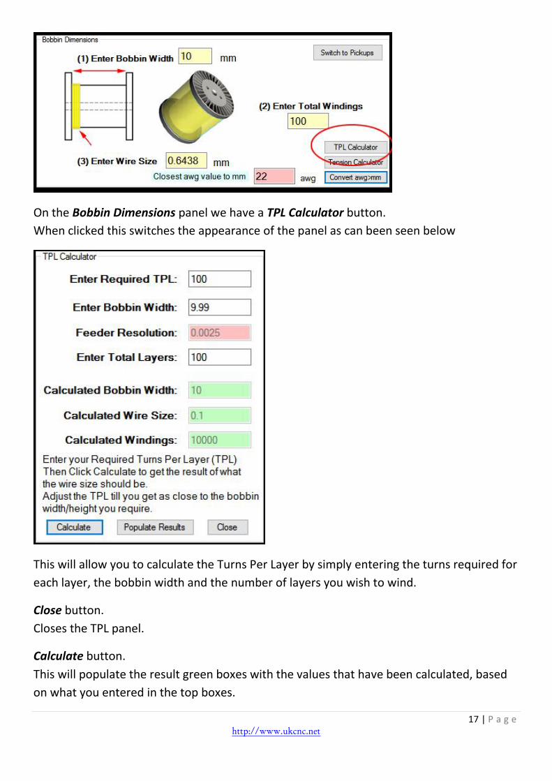
On the Bobbin Dimensions panel we have a TPL Calculator button.
When clicked this switches the appearance of the panel as can been seen below
This will allow you to calculate the Turns Per Layer by simply entering the turns required for
each layer, the bobbin width and the number of layers you wish to wind.
Close button.
Closes the TPL panel.
Calculate button.
This will populate the result green boxes with the values that have been calculated, based
on what you entered in the top boxes.

18 | P a g e http://www.ukcnc.net
Populate Results button.
This will take the values that have just been calculated and populate the main bobbin
dimensions screen.
Above after clicking the Populate Results button.

19 | P a g e http://www.ukcnc.net
On the Bobbin Dimensions panel, we have a Tension Calculator button.
When clicked this switches the appearance of the panel as can been seen below
Close button.
Closes the Tensioner panel.
Calculate button.
This will take the wire size entered in the top box and give the results in the green boxes.

20 | P a g e http://www.ukcnc.net
On the Bobbin Dimensions panel we have a Switch to Pickups button.
When clicked this switches the appearance of the panel as can been seen below
We now have a guitar pickup picture displayed and also a few more options.

21 | P a g e http://www.ukcnc.net
The main thing that has changed is that we now have extra variables that can be set and
saved against the bobbin.
These are shown in green and are for information only. They do not affect the way the
pickup is wound.
Also, you will notice that we now have a Populate Default Pickups button.
When you first run the software you will see that nothing has been saved yet.
But by click the Populate Default Pickups button it will populate the database with a set of
common guitar pickups.
Any of these once loaded can be changed and saved back to suit your custom needs.

22 | P a g e http://www.ukcnc.net
A new feature is the Mixed TPL Mode button.
A lot of our customers that are winding Guitar Pickups are now using the Scripting Engine
for creating some Mixed Turns Per Layer(TPL) to build up their coil shapes into various
shapes and also to try and get close to a Scatter Wind effect.
We do have a Beta Scatter Winding tab in the software, but it is based on a different
position per revolution, rather than allowing for mixed TPL setups, that can then be merged
together.
A quick couple of paragraphs on Scatter Winding first.
What is scatter winding?
When wire is wound into coils on a pickup, the most basic definition of scatter-wound
means “non-uniform.”
Imagine a spool of thread that doesn’t have thread on it yet that you’re going to wrap
thread around.
If you were to wrap that thread in a uniform way, you would start the wrap on one side,
with each consecutive wrap following the other until you reach the other side, then start
wrapping in the other direction and crisscross until you were finished.
If you were to wrap the same thread in a non-uniform way where you wrap a few times on
one side, then go straight to the other side and get a few wraps there, then to the middle
and “fill” the spool in a non-uniform way, that’s a scatter-wind.

23 | P a g e http://www.ukcnc.net
Does scatter winding have a “standard?”
No. Scatter-winding is particular to manufacturer. Seymour Duncan will scatter-wind
differently than Lindy Fralin and differently than other pickup makers and so on. In addition,
there are also pickup makers who scatter-wind by hand, and still others who will use a
machine. There is no single “right way” to scatter-wind.
What pickup makers do is experiment with different scatter-wind techniques until they find
one they think works well, and go with that.
One of the down sides of using the scripting is that for higher speeds, each command will
need to be ramped up and ramped down. If not then the motors will just stall.
Just like any CNC machine out there, that is using Stepper motors, they need to be ramped.
Now the big question or observation I get is that in the Automated Tab, you can setup all
the parameters of the pickup you wish to wind, click on the start button and away the
machine will go, without it having to ramp up and down each layer.
The main reason we can do this is because the feeder (with small wire) is never running
faster than the bobbin motor and the speed it is running at 99% of the time means we can
change direction of the feeder without ramping.
So we calculate total windings, along with the turns per layer and send this as one
command to the firmware. You will still get a ramp at the beginning and also a ramp at the
end of the winding. But no ramping in-between layers as the firmware simply changes
direction of the feeder when it hits it desired TPL.
With the scripting we send one command for each layer.
So now to try and make winding a little bit smoother, we have added a new button on the
Automated tab Pickup Screen. This is called Mixed TPL mode and allows you to save
different combinations of winding sets and to execute them one after the other.
You will still need to ramp up and down for each set, but depending on how many windings
are in a set and how many total winds you need to do, it will reduce the ramping per layer a
lot.
Main rules to stick to are to make sure each winding set you create has at least two layers
and that total layers are a whole number (Integer).
The reason for this is so you do not lose your zero point in-between the winding sets. If you
try to send say 10 windings at a 1.0mm pitch for the first layer and then send 5 windings at

24 | P a g e http://www.ukcnc.net
1.0mm for the next layer, then obviously the starting point for the next command is not at
zero point and it would actually be 5.0mm.
In the scripting engine you could send a movement command to bring it back to zero, but
for this feature under the Mixed TPL Mode, that will not be possible.
So a little bit of a trade off, but it should suit most people’s needs.
Here are some screenshots with instructions on how it works.
GUI layout may look a little different as screenshots are from V1.8 software.

30 | P a g e http://www.ukcnc.net
Standard Script Engine – Tab This tab allows us to have more control over the coil winding process by allowing us to
create a series of commands to control bobbin windings and feeder movement.
These commands can be built up and saved as a script for later use.
Creating the commands is very simple by using the GUI interface to choose the options you
want for each new command and press the Add Command button.

31 | P a g e http://www.ukcnc.net
Below we will go through each option panel and detail what they are.
The objects for the other options on the panel are as follows:
Ramping Configuration group box.
We use stepper motors on our machines then to get them to higher speeds we need to
ramp up the motor speed gradually.
You have two variables you can set to get the desired curve as such.
The Steps variable is the divider of the target frequency that we want the bobbin motor to
run at. So if the software calculated that the bobbin motor should run at 1000kHz and the
steps box is set to 100 then we can see that the steps would be 1000/100 = 10 Hz
increments.
The Pause variable is the time between each increment.
Homing Configuration group box.
Feeder Homing Offset.
Sets the offset distance that the feeder arm will move away from the limit switch when the
Home Feeder button is clicked.
For example, if it is set to 10mm then when the Home Feeder button is clicked the feeder
arm will move to the left until it gets to the limit switch on the machine. It will then move to
the right 10mm.
This option is only available for machines with the homing/limit switches installed.
Wire Guide Homing Offset.
Sets the offset distance that the feeder arm will move away from the limit switch when the
Home Wire Guide button is clicked.
For example, if it is set to 1mm then when the Home Wire Guide button is clicked the Wire
Guide will move to the back until it gets to the limit switch on the machine. It will then
move forward 1mm.
This option is only available for 3-Axis Machines.

32 | P a g e http://www.ukcnc.net
Reply is the answer coming back from the Coil Winding Machine after each command is
sent.
Hardware Status shows of the Coil Winding Machine is connected or not connected to the
computer.
The Load/Save Settings group box.
Allows you to save and remove scripting parameters.
When clicking the Save button it will ask for a name that you wish to call the set and save
all the parameters to the registry. If you wish to remove the saved set from the registry,
then click the Remove button and it will delete it.
The Status panel has the following objects
Winds Completed display.
Displays the amount of winding that have been wound.
Feeder Position display.
Displays the position of the feeder arm on the machine.
RPM display.
Displays the speed that the bobbin motor is running at.
Commands Processed display.
Displays the amount of commands that have been processed.
Guide Position display.
Displays the position of the wire guide on the machine. Only for 3-Axis machines.
Reset button.
Pressing this button will reset the feeder position to zero.

33 | P a g e http://www.ukcnc.net
Manual Speed Override checkbox.
If checked then when the Start button is clicked the software will pass control over to the
manual speed controller on the controller box.
The manual controller dial needs to be fully turned to the left before it will start to wind
and the speed of the bobbin motor and feeder arm will increase or decrease depending on
the position of the dial.
Ramping will be disabled for this mode as not needed and it will be down to control of the
user to make sure the speed is controlled so no jamming of the motors will occur.
The Controls panel has the following objects
Start button.
Clicking this button starts the winding routine starting with the first command in the script
window.
Stop button.
Clicking this button stops the winding routine.
Pause/Resume button.
While winding is in progress and you wanted to pause the machine then click this button. It
will then turn to a flashing Resume status and clicking it again will allow the machine to
carry on from where it was paused.
While pause you can cancel the winding routine by pressing the stop button.
Also while paused the Left and Right button can be used to jog the feeder arm to a new
position. This will not increment the feeder position and can be used for adjustments
needed without having to restart the whole winding routine from the beginning.
Home Feeder button.
This can only be used if there are limit/homing switches installed on the machine. Based on
the variable set in the Feeder Homing Offset will determine the distance that the feeder
arm will travel away from the limit switch once it has been triggered.
Disengage Motors button.
When clicked this will disengage the motors so they can be turned by hand.
The motors will automatically re-engage when start or jog buttons are clicked.

34 | P a g e http://www.ukcnc.net
You will not be able to disengage the motors when paused, but if you need to move the
motors at this point, then simply turn the power off to the motors via the switch. Do the
adjustments and then turn the power back on before pressing resume in the software.
Goto Zero button.
Pressing this button will tell the feeder arm to return to its zero position.
Return to Zero checkbox.
If this is checked then when the machine has finished its winding routine the feeder arm
will automatically move back to the zero position.
Home Wire Guide button.
This can only be used if there is a 3rd-Axis installed on the machine. Based on the variable
set in the Guide Homing Offset will determine the distance that the wire guide will travel
away from the limit switch once it has been triggered.
Reverse button.
This is a manual jog for the bobbin motor and when clicked the bobbin motor will move in
the reverse direction.
Forward button.
This is a manual jog for the bobbin motor and when clicked the bobbin motor will move in
the forward direction.
Left button.
This is a manual jog for the feeder arm and when clicked the feeder arm will move to the
left.
Right button.
This is a manual jog for the feeder arm and when clicked the feeder arm will move to the
right.
Back button.
This is a manual jog for the Wire Guide and when clicked the wire guide will move to the
Back. Only available on 3-Axis machines.
Forward button.
This is a manual jog for the Wire Guide and when clicked the wire guide will move to the
Back. Only available on 3-Axis machines.

35 | P a g e http://www.ukcnc.net
Feeder Travel per click variable.
Sets the travel in millimetres that the feeder arm will move if either the Left or Right
buttons are clicked.
Bobbin Travel per click variable.
Sets the amount of revolutions that the bobbin motor will move if either the Forward or
Reverse buttons are clicked.
Wire Guide Travel per click variable.
Sets the travel in millimetres that the wire guide will move if either the Back or Forward
buttons are clicked. Only available on 3-Axis machines.
Increment Counter When Jog Buttons Clicked Checkbox.
When checked this will update the counters when the jog buttons are clicked.
The Script Window panel has the following objects
The Script window itself is where each command is appended to and built up.
The command structure is very simple to understand and a quick breakdown is.
G1 – This lets the software know it is a Standard command.
SR1 – Sets the Start Ramp to on.
WS000.1000 – Sets the Wire Size or pitch to 0.1mm to move per wind.
WI000050 – Sets the amount of winds to be completed.
BD1- Sets the Bobbin Direction to forward
WD1 – Sets the Wire Direction to move to the right.
PA0 – Tells the software not to pause for each layer.

36 | P a g e http://www.ukcnc.net
SP1000 – Sets the speed to 1000 RPM
FR1 – Sets the Finish Ramp to on.
This will again interpolate the bobbin and feeder motors so that they start and stop at the
exact time across each wind.
If you just wanted the feeder arm to move and not the bobbin motor then simply set the
windings to zero (WI000000). When this command is then executed it would move the
feeder arm 0.1mm.
The same if you just wanted the bobbin motor to do 50 turns without the feeder moving.
Set the wire size to zero (WS000.0000).
There are also another set of commands that can be added to your script.
*comment - Anything with a * in front of it will be treated as a comment.
M1–message -Pauses the script and allows a message to be displayed.
M2-Start Loop10 – Start of loop command. Any commands inserted between the M2 and
M3 commands will be repeated. In this example 10 times.
M3-End Loop – End of loop command.
M4-Zero Windings Counter – Zero the Total Windings counter
M5-Zero Feeder Position – Zero the Feeder Position.
M6-Pause100 – Pause between commands
M7-Move Feeder To Zero – Move Feeder to zero position.
Rather than manually adding commands, we would recommend using the GUI Add
Command buttons to build the script as each command has to be in this exact format as
shown above.
Clear Window button.
Clears the current window and deletes your script. If it has not been saved beforehand then
you will not be able to recover it.
Load Script button.
Loads a script from the computers file system into the script window.

37 | P a g e http://www.ukcnc.net
Save Script button.
Saves the script in the Script Windows to the computers file system and allows you to
choose where to save it and what filename to call it.
Analyse Script button.
This runs through your script and then opens up a separate window with the result of your
script.
As you can see, our command1 of:
G1-SR1-WS000.1000-WI000050-BD1-WD1-PA0-SP1000-FR1
Instructs the machine to do 50 windings, with the feeder moving 0.1mm per wind.
Below we will look at the GUI interface for adding these commands.

38 | P a g e http://www.ukcnc.net
The Information panel has the following objects
Disable Hover Help Tips checkbox.
You can move the mouse over any object within the software and if left over that object for
a certain amount of time a Hover Tip will appear giving you information on that object.
By checking this box then it will stop these hover tips appearing.
On the Information group you have two options that will open up different windows.
Add Winding or Movement Commands button.
Clicking on this option brings up the panel below:

39 | P a g e http://www.ukcnc.net
The Standard and Advanced Commands panel is shown above.
40 | P a g e http://www.ukcnc.net
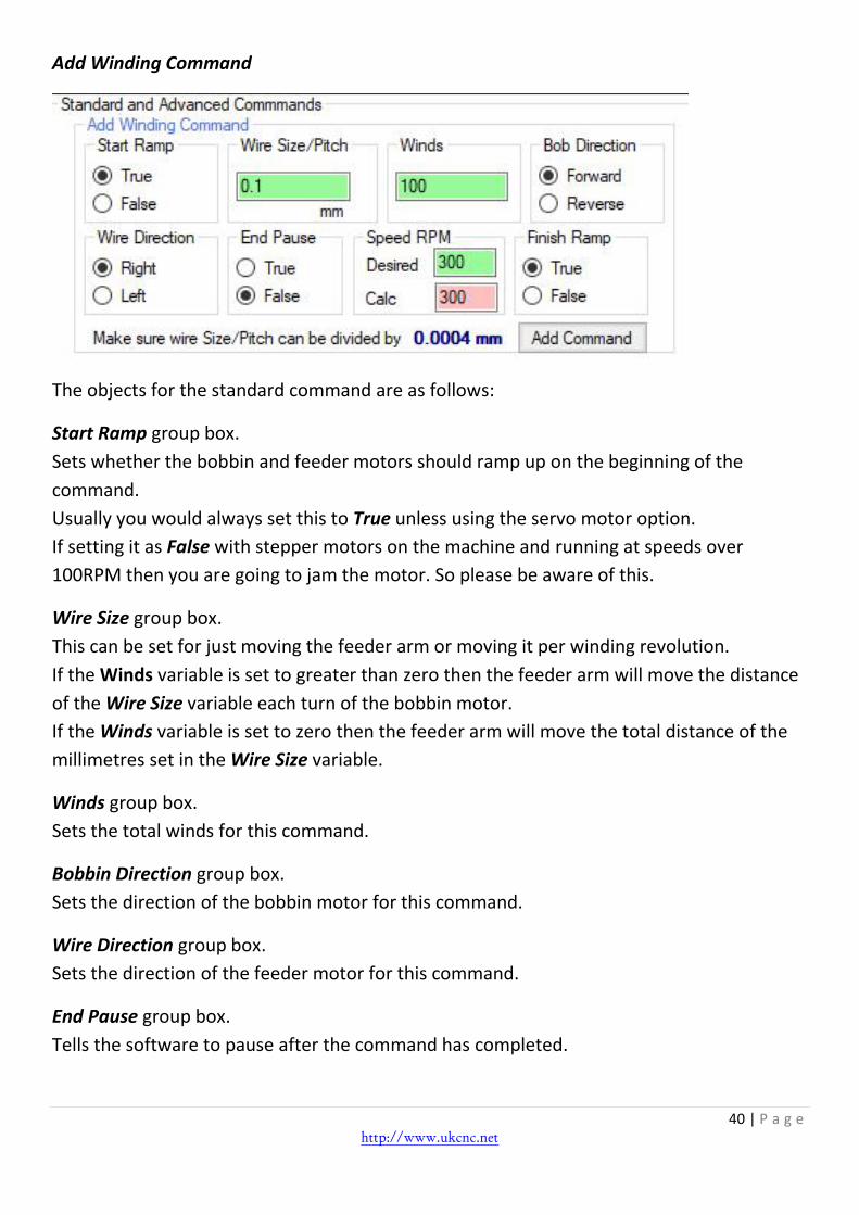
Add Winding Command
The objects for the standard command are as follows:
Start Ramp group box.
Sets whether the bobbin and feeder motors should ramp up on the beginning of the
command.
Usually you would always set this to True unless using the servo motor option.
If setting it as False with stepper motors on the machine and running at speeds over
100RPM then you are going to jam the motor. So please be aware of this.
Wire Size group box.
This can be set for just moving the feeder arm or moving it per winding revolution.
If the Winds variable is set to greater than zero then the feeder arm will move the distance
of the Wire Size variable each turn of the bobbin motor.
If the Winds variable is set to zero then the feeder arm will move the total distance of the
millimetres set in the Wire Size variable.
Winds group box.
Sets the total winds for this command.
Bobbin Direction group box.
Sets the direction of the bobbin motor for this command.
Wire Direction group box.
Sets the direction of the feeder motor for this command.
End Pause group box.
Tells the software to pause after the command has completed.

41 | P a g e http://www.ukcnc.net
The Pause button will change to Resume and will needed to be clicked before the next
command is executed.
Speed RPM group box.
Desired speed is the variable that will tell the machine what speed you want the bobbin
motor to run at.
As the bobbin motor and feeder motor are interpolated, then most of the time the speed of
the bobbin motor will be divided down to set the speed of the feeder arm motor to suit and
keep that interpolation correct. But if you require the wire size or movement pitch to be a
large number that requires the feeder arm motor to run faster than the bobbin motor, then
the bobbin motor will automatically drop and the calculated speed will be displayed below.
Finish Ramp group box.
Sets whether the bobbin and feeder motors should ramp down at the end of the command.
Usually you would always set this to True unless using the servo motor option.
Add Command button.
After setting all the other options above this button, you simply click this button to add the
command to the script window.
Add Degree Winding Command
The objects for the advanced command are as follows:
Start Ramp group box.
Sets whether the bobbin and feeder motors should ramp up on the beginning of the
command.

42 | P a g e http://www.ukcnc.net
Wire Size group box.
This is the distance that the feeder arm will move per degree movement of the bobbin
motor.
Bobbin Degrees group box.
Sets the movement in degrees of the bobbin motor for this command.
Bobbin Direction group box.
Sets the direction of the bobbin motor for this command.
Wire Direction group box.
Sets the direction of the feeder motor for this command.
End Pause group box.
Tells the software to pause after the command has completed.
The Pause button will change to Resume and will needed to be clicked before the next
command is executed.
Speed group box.
This variable that will tell the machine what speed you want the bobbin motor to run at.
Finish Ramp group box.
Sets whether the bobbin and feeder motors should ramp down at the end of the command.
Add Command button.
After setting all the other options above this button, you simply click this button to add the
command to the script window.

43 | P a g e http://www.ukcnc.net
Add Wire Guide Movement Command
Guide Movement group box.
This is the distance that the wire guide will move.
Wire Guide Direction group box.
Sets the direction of the Wire Guide for this command.
End Pause group box.
Tells the software to pause after the command has completed.
The Pause button will change to Resume and will needed to be clicked before the next
command is executed.
Speed group box.
This variable that will tell the machine what speed you want the wire guide motor to run at.
Add Command button.
After setting all the other options above this button, you simply click this button to add the
command to the script window.

44 | P a g e http://www.ukcnc.net
Add Winding or Movement Commands button.
Clicking on this option brings up the panel below:

45 | P a g e http://www.ukcnc.net
*comment - Anything with a * in front of it will be treated as a comment.
M1–message -Pauses the script and allows a message to be displayed.
M2-Start Loop with Count – Start of loop command. Any commands inserted between the
M2 and M3 commands will be repeated. In this example 10 times.
M3-Finish Loop – End of loop command.
M4-Zero Windings Counter – Zero the Total Windings counter
M5-Zero Feeder Position – Zero the Feeder Position.
M6-Pause100 – Pause between commands
M7-Move Feeder To Zero – Move Feeder to zero position.
Add Command button.
After setting all the other options above this button, you simply click this button to add the
command/commands to the script window.

46 | P a g e http://www.ukcnc.net
The Standard Scripting engine also allows saved bobbins from the Automated Tab section
to be added as a Scripting command.
This is mainly for customers using the Scripting engine of the 200mm coil winder that need
to place movement command when winding sections over the length of the coil.
They could have done this before, but using the Scripting Winding commands meant that
they had to ramp up and ramp down for each layer.
So now they can wind a section of their coil with a saved bobbin and then move to the next
section and wind that area with the same bobbin or a different one and no ramping
between layers.
This also may be useful for people with the Mini Coil Winder that are using the Mixed TPL
mode.
Instead of using Mixed TPL mode they could use the Scripting Engine and not have to worry
about their layers being an integer as it has a Move Feeder to Zero option or if you know
your finish position then you could enter a movement command to move the feeder to the
next start position.
Ideal for winding different sections where you need to wind a area

47 | P a g e http://www.ukcnc.net
with a set amount of winds and then move to the next section and start another set winding. Choose the Bobbin from the drop-down list and click ADD.
Absolute Scripting Mode – Tab With the new ARM Controller MKII, we have now on-board Flash memory that can be used
for buffering loads of small commands. This removes any small delays that can be caused
by the USB communications latency.
Unlike the Standard Scripting Engine which is Incremental positioning for each command,
this is absolute positioning on each command.
For example if you set the bobbin position to be 10.00 and feeder position to be 5.00 in a
command (10.00,5.00,100,) then it will rotate the bobbin 10 times and move the feeder by
5mm. If you then send a command (11.00,6.00,100,) it will move the bobbin by 1 turn and
the feeder by 1mm, at a speed of 100 RPM.

48 | P a g e http://www.ukcnc.net
The scripts can be created in Excel spreadsheet and saved as a CSV file. This can then be
loaded into the script window. The format for each command is:
Bobbin position, Feeder position, Speed, Comment
If the bobbin, feeder and speed are set to zero (0,0,0,Paused) then the script will pause and
display the comment.
You will need to create your own ramping if required as shown in the example.

49 | P a g e http://www.ukcnc.net
The Absolute Scripting panel has the following objects.
Script Line display.
Displays which line of the script is being executed out of the total number of lines loaded.
Clear Script button.
Clears the current window and deletes your script. If it has not been saved beforehand then
you will not be able to recover it.
Load Script button.
Loads a CSV script from the computers file system into the script window.
Save Script button.
Saves the script in the Script Windows to the computers file system and allows you to
choose where to save it and what filename to call it.
Enumerate Script button.
After manually editing the script in the window, you will need to enumerate it by clicking
this button.
The check for invalid characters should not now be needed and was there while we were
testing. But handy to check if your script file has any hidden characters in there.

50 | P a g e http://www.ukcnc.net
The Status panel has the following objects.
Bobbin Position display.
Displays the position of the bobbin on the machine.
Feeder Position display.
Displays the position of the feeder arm on the machine.
Completed Windings display.
Displays the amount of winding that have been wound.
RPM display.
Displays the speed that the bobbin motor is running at.
Reset button.
Pressing this button will reset the bobbin and feeder position to zero.
Reverse button.
This is a manual jog for the bobbin motor and when clicked the bobbin motor will move in
the reverse direction.

51 | P a g e http://www.ukcnc.net
Forward button.
This is a manual jog for the bobbin motor and when clicked the bobbin motor will move in
the forward direction.
Left button.
This is a manual jog for the feeder arm and when clicked the feeder arm will move to the
left.
Right button.
This is a manual jog for the feeder arm and when clicked the feeder arm will move to the
right.
Feeder Travel per click variable.
Sets the travel in millimetres that the feeder arm will move if either the Left or Right
buttons are clicked.
Bobbin Travel per click variable.
Sets the amount of revolutions that the bobbin motor will move if either the Forward or
Reverse buttons are clicked.
The Control panel has the following objects
Start button.
Clicking this button starts the buffering routine first and once all the commands are
buffered to the controller, then it will start winding.
Stop button.
Clicking this button stops the winding routine.

52 | P a g e http://www.ukcnc.net
Pause/Resume button.
While winding is in progress and you wanted to pause the machine then click this button. It
will then turn to a flashing Resume status and clicking it again will allow the machine to
carry on from where it was paused.
Because of the nature of the absolute scripting, it is not possible to use ramping. So again
this should only be used at low speeds.
Home button.
This can only be used if there are limit/homing switches installed on the machine. Based on
the variable set in the Homing Configuration will determine the distance that the feeder
arm will travel away from the limit switch once it has been triggered.
Speed Override checkbox.
If checked then the speed is ignored in the script and it will use the value set. You have no
ramping when this is selected, so only suitable for low speeds.
Reply Frequency box.
Due to the speed and small movements, it can sometimes not be possible to receive replies
back from the controller as quick as they are being executed and you could get some
stalling or lockups. We recommend keeping this set to 2 or above.
Buffer Delay box.
It seems that Microsoft changed it’s USB routines/drivers since releasing Windows 10 build
1803 and this has caused some issues with Absolute Scripting and the buffering routine
when writing commands to the Flash Memory of the ARM Controller.
If you find you have issues with the buffering or any weird outcome from your script then
change this buffer delay value to 20 or above.
Homing Configuration group box.
Sets the offset distance that the feeder arm will move away from the limit switch when the
Home button is clicked.
For example, if it is set to 10mm then when the Home button is clicked the feeder arm will
move to the left until it gets to the limit switch on the machine. It will then move to the
right 10mm.
By ticking the Use Homing Offset on Start option will cause the machine to home when the
Start button has been clicked. The machine will then home before the winding starts.
This option is only available for machines with the homing/limit switches installed.

53 | P a g e http://www.ukcnc.net
Disengage Motors button.
When click this will disengage the motors so they can be turned by hand.
The motors will automatically re-engage when start or jog buttons are clicked.
You will not be able to disengage the motors when paused, but if you need to move the
motors at this point, then simply turn the power off to the motors via the switch. Do the
adjustments and then turn the power back on before pressing resume in the software.
ABOUT button.
This will display a short description of the commands, but also allow you to load a sample
script when the button is clicked.
54 | P a g e http://www.ukcnc.net
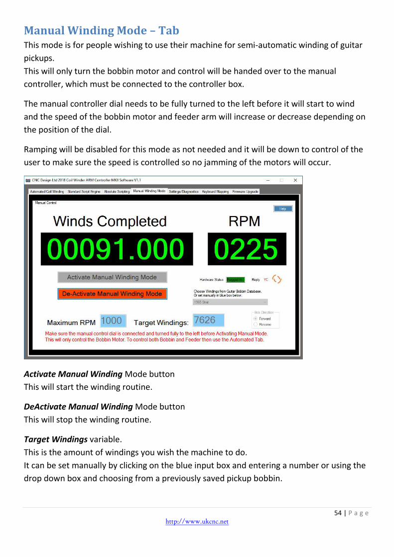
Manual Winding Mode – Tab This mode is for people wishing to use their machine for semi-automatic winding of guitar
pickups.
This will only turn the bobbin motor and control will be handed over to the manual
controller, which must be connected to the controller box.
The manual controller dial needs to be fully turned to the left before it will start to wind
and the speed of the bobbin motor and feeder arm will increase or decrease depending on
the position of the dial.
Ramping will be disabled for this mode as not needed and it will be down to control of the
user to make sure the speed is controlled so no jamming of the motors will occur.
Activate Manual Winding Mode button
This will start the winding routine.
DeActivate Manual Winding Mode button
This will stop the winding routine.
Target Windings variable.
This is the amount of windings you wish the machine to do.
It can be set manually by clicking on the blue input box and entering a number or using the
drop down box and choosing from a previously saved pickup bobbin.

55 | P a g e http://www.ukcnc.net
Bobbin Direction group box.
Sets the direction of the bobbin motor for this command.
Winds Completed display.
Displays the amount of winding that have been wound.
RPM display.
Displays the speed that the bobbin motor is running at.
Reply is the answer coming back from the Coil Winding Machine after each command is
sent.
Hardware Status shows of the Coil Winding Machine is connected or not connected to the
computer.

56 | P a g e http://www.ukcnc.net
Settings/Diagnostics – Tab
This tab has a mixture of settings and also diagnostics displays.
The diagnostic displays you do not have to really worry about and more there for trouble
shooting if needed.
Below we will go through the settings that can be changed to suit your machine and any
add-ons you use.
57 | P a g e http://www.ukcnc.net
Wire Guide PPmm variable.
For machines with a 3rd Axis installed, this will be the Pulses Per 1mm of movement.
Wire Guide Resolution display.
Displays the resolution of the Wire Guide.
Wire Guide Jog Speed variable.
Sets the movement speed of the Wire Guide.
Current Config display.
This displays what configuration has been detected when the machine is plugged into your
computer or displays what has been manually set.
Choose Machine button.
This will launch the startup screen and allow you to change machine type.
Backup button.
This backs up all the bobbins and all the settings for all tabs within the software and allows
you to save as a .REG file.
If you move the software onto a new machine then make sure you use this button to back
up the settings and then copy the .REG file over to your new computer.
Next just double click the .REG file and follow the instructions on the screen.
When you launch the software on the new machine it should pick up all the settings.
Bobbin Motor Frequency display.
This value is automatically calculated on the value of the SPBR variable.
Bobbin Motor SPBR variable.
This variable sets the Steps Per Bobbin Revolution needed to suit the Coil Winding Machine
attached to your computer.
Feeder Resolution display.
Displays the resolution of the feeder arm.
This value is automatically calculated on the value of the SPFR variable and BSP variable.
SPBR variable.
This variable sets the Steps Per Feeder Revolution needed to suit the Coil Winding Machine
attached to your computer.

58 | P a g e http://www.ukcnc.net
BSP variable.
This variable sets the Ballscrew Set Pitch needed to suit the Coil Winding Machine attached
to your computer.
Pause Boundary variable
If the pause button is used near the start of each layer and at the end of each layer then it
can throw either the position read off or not complete the pause.
This is because when the Pause key is clicked when winding and there is not enough travel
left in the winding for a ramp down and then a ramp up after pause.
By the default the Pause boundary is 1.0mm into the wind and the width of bobbin minus
1.0mm.
Set Default Startup variable
Sets which tab should display on start-up of the software.
Enable Timeout Alert checkbox
Enables the command timeout value for communications. If no reply has come back to the
software from the controller in the value entered, then it will cause an alert box to be
displayed. Used for de-bugging any issues and usually left unchecked.
Enable Command Pause checkbox
Enables the pause between commands sent from the Standard Scripting Engine.
This is useful if small commands are sent and you need to slow it down to avoid
communication conflicts.
Limit Switches installed checkbox
If you have installed the limit/homing and emergency stop kit onto your Coil Winder then
you need to check this option to let the software know. It will then enable the homing
features of the software.
Emergency Stop installed checkbox
If you have installed the limit/homing and emergency stop kit onto your Coil Winder then
you need to check this option to let the software know. It will then enable the extra
features of the software.
Reverse Bobbin Motor checkbox
Will reverse the direction of the bobbin motor to suit motor attached to your machine.
Reverse Feeder Motor checkbox
Will reverse the direction of the feeder motor to suit motor attached to your machine.

59 | P a g e http://www.ukcnc.net
Safety Hood checkbox.
For use on machines that have a hood fitted.
3rd Axis Installed checkbox.
For machines that have a 3rd Axis installed such as the wire guid eon the 200mm MK5
machine.
Save button.
Saves the settings that have been set in all the variables above if using a Custom
Configuration.
Bobbin Jog Speed variable.
Sets the speed of the bobbin motor when using the Jog buttons. This is set in RPM.
Feeder Jog Speed variable.
Sets the speed of the feeder arm motor when using the Jog buttons. This is set in
frequency, rather than RPM.
Homing Seek Feed variable.
Sets the speed of the Feeder motor when homing is at the seek stage. This is set in RPM.
When the Homing button is clicked in the software, the feeder will move to the limit switch
and when triggered it will move away from the limit switch and then back again for another
trigger. This is known as the seek stage and is used so that the feeder always ends up in the
same position even though the initial homing speed can vary.

60 | P a g e http://www.ukcnc.net
Homing Seek Offset variable.
Sets the offset distance that the feeder will travel away from the limit switch when in seek
stage.
Limit Trigger Travel variable.
If you accidently trigger a limit switch then the controller will alert the software and move
the feeder away from the limit switch. This is the travel distance that the feeder would
move once triggered.
The only control on the middle section is the Reset Flash button.
This is only to be used when installing a new Flash Chip on the controller board. It then
resets the counters on the controller and initialises the new memory installed.
The other display boxes are for information when diagnosing any issues.
At the bottom of the tab we also have some other settings.
Firmware button.
When clicked it displays the current Firmware of the connected Coil Winding Machine.
Under the Change Colours group box we have:
Background button.
Changes the background colour of each tab.

61 | P a g e http://www.ukcnc.net
Foreground button.
Changes the foreground colour of each tab.
Border button.
Changes the border colour of each tab.
Reset to Default button.
Sets all colours back to the original style.
Info box.
Clicking on URL will take you to product web page.

62 | P a g e http://www.ukcnc.net
Keyboard Mapping – Tab
This tab lets you map keyboard keys to the buttons within the software.
By selecting the drop-down box next to each control, you can map this to a key on the
keyboard. Or by simply clicking on the button image and then pressing a key.
Also these keys can be mapped to inputs on the controller board that have switches
attached.

63 | P a g e http://www.ukcnc.net
Upgrading the Firmware. With the new ARM Controller MKII you can no longer upgrade the firmware via the
software and will need to use a JTAG programmer that is supplied with the machine.
Please check the download area of our website for the full instructions, depending on what
machine you have.
http://www.ukcnc.net/index.php/downloads/