Embed Size (px)
Citation preview
1
Software Oriented Data Monitoring System Phani Nandan K. and Pavan Kumar K.
One area of biomedical instrumentation that is becoming increasingly familiar to the
general public is that of patient monitoring. Here electronic equipment provides a
continuous watch over the vital characteristics and parameters of the critically ill. In the
coronary care and the intensive care units in the hospitals, thousands of lives have been
saved in the recent years because of the careful and accurate monitoring afforded by this
equipment.
Essentially, patients are monitored because they have an unbalance in their body systems.
This can be caused by a heart attack or stroke, which can drastically disturb these
systems. By continual monitoring, the patient problems can be detected as they occur and
remedies taken before these problems get out of hand.
The need for intensive care and patient monitoring has been recognized for centuries.
The 24-hour nurses for the critically ill patient has, over the years, become a familiar
part of the hospital scene. Nurses are still there but roles have changed somewhat, for
they now have powerful tools at their disposal for acquiring and assimilating
information about the patients under their care. They are therefore able to render better
service to a larger number of patients and are better able to react promptly and properly
to an emergency situation. With the capability of providing an immediate alarm in the
event of certain abnormalities in the behavior of the patients‟ critical data, monitoring
equipment makes it possible to summon a physician or nurse in time to administer
emergency aid often before permanent damage may occur.
The 21st century has been the age of computers and information technology. Computers
and processors are used in various automation systems with great accuracy and
reliability.
The field of telecommunications has also seen an enormous advancement with new
technologies being introduced frequently, particularly the mobile phone technology.
Automation, precision and accuracy are a must in the medical field and now-a-days
machines are replacing the less accurate humans.
Patients having critical conditions are admitted in the Intensive Care Unit (ICU) for
monitoring their condition regularly. Different sensors are attached to their bodies and a
dedicated person constantly monitors the data. But by making use of advance mobile
technology, messages containing the real time parameters of the patient placed in ICU
can be monitored and sent to the concerned doctor even if he is busy attending other
patients, thus saving his valuable time. A typical system implementing these features
would look like the figure below.
2
Fig 1.1 Schematic diagram of Real time Patients’ data Monitoring System
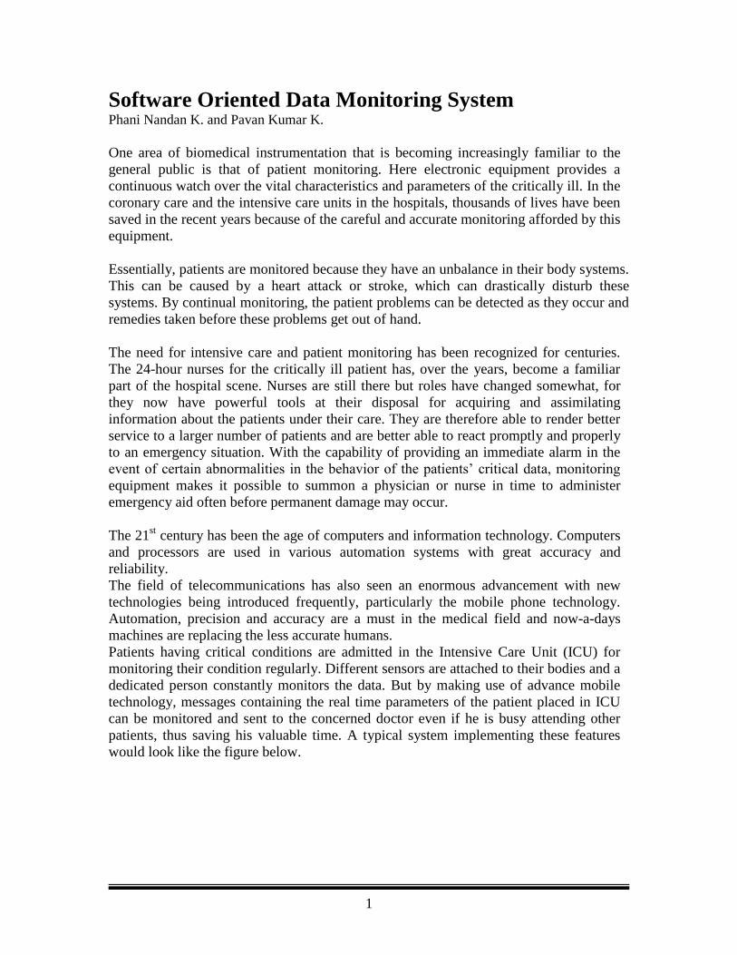
Fig 1.2 Block diagram of Real time Patients’ data Monitoring System The patients‟ temperature and the heart rate measured by the sensors are sent to the
ADC. The ADC consists of 8 input channels. Here the analog inputs i.e. the critical
parameters of the patient are converted into digital form and are sent to the computer
through the parallel port. Since the parallel port of the computer has only 5 input pins a
Multiplexer is used so that a nibble (4 bits) of data is sent at a time. This data in the
computer is sent to the Cell phone using serial port of the computer. This cell phone
sends SMS to the Doctors cell at appropriate intervals.
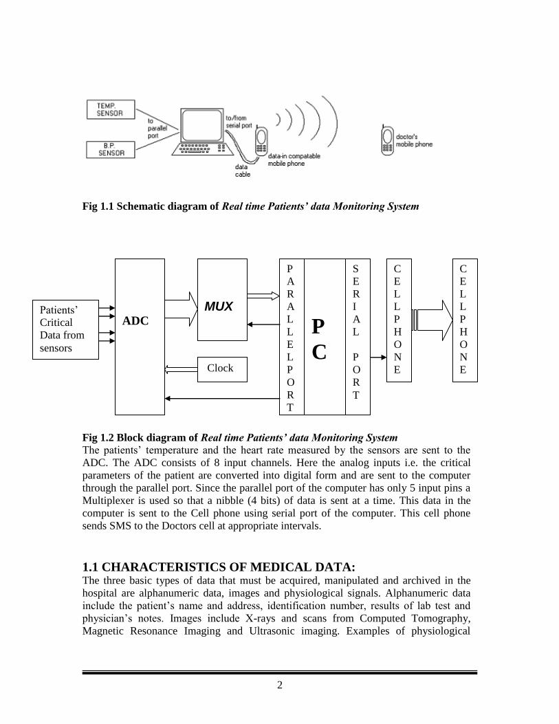
1.1 CHARACTERISTICS OF MEDICAL DATA: The three basic types of data that must be acquired, manipulated and archived in the
hospital are alphanumeric data, images and physiological signals. Alphanumeric data
include the patient‟s name and address, identification number, results of lab test and
physician‟s notes. Images include X-rays and scans from Computed Tomography,
Magnetic Resonance Imaging and Ultrasonic imaging. Examples of physiological
ADC
MUX
Clock
P
A
R
A
L
L
E
L
P
O
R
T
P
C
S
E
R
I
A
L
P
O
R
T
C
E
L
L
P
H
O
N
E
Patients‟
Critical
Data from
sensors
C
E
L
L
P
H
O
N
E
3
signals are the electrocardiogram (ECG), the electroencephalogram (EEG) and BP
tracing.
Fig 1.3 Types of Medical Data
Quite different systems are necessary to manipulate each of these three types of data.
Alphanumeric data are generally managed and organized into a database using a
general-purpose mainframe computer.
Image data are traditionally archived on film. However, we are evolving towards picture
archiving and communication systems (PACS) that will store images in digitized form
on the optical disks and distribute them on demand over a high-speed Local Area
Network (LAN) to very high-resolution graphics display monitors located throughout a
hospital.
On the other hand, physiological signals that are monitored during surgery in the
operating room require real time processing. The clinician must know immediately if
the instrument finds abnormal readings as it analyses the continuous data.
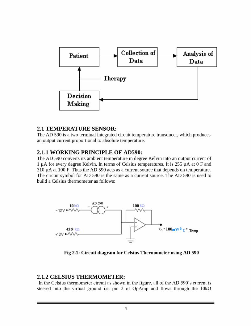
1.2 BASIC ELEMENTS OF A MEDICAL CARE SYSTEM: The block diagram below illustrates the operation of the medical care system. Data
collection is the starting point in the health care. The clinician asks the patient questions
about medical history, records the ECG, and does blood tests and other tests in order to
define the patient‟s problem. Of course medical instruments help in some aspects of this
data collection process and even do some processing of data. Ultimately, the clinician
analyses the data collected and decides what the basis of the patient‟s problem is. This
decision of diagnosis leads the clinician to prescribe a therapy. Once the therapy is
administrated to the patient, the process continues along the closed loop as shown in the
figure with more data collection and analysis until patient‟s problem is rectified.
4
Fig 1.4 Basic elements of a medical care system
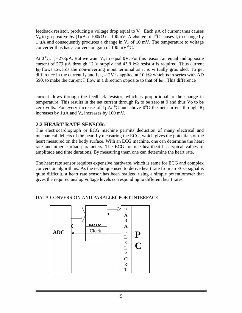
2.1 TEMPERATURE SENSOR: The AD 590 is a two terminal integrated circuit temperature transducer, which produces
an output current proportional to absolute temperature.
2.1.1 WORKING PRINCIPLE OF AD590: The AD 590 converts its ambient temperature in degree Kelvin into an output current of
1 µA for every degree Kelvin. In terms of Celsius temperatures, It is 255 µA at 0 F and
310 µA at 100 F. Thus the AD 590 acts as a current source that depends on temperature.
The circuit symbol for AD 590 is the same as a current source. The AD 590 is used to
build a Celsius thermometer as follows:
Fig 2.1: Circuit diagram for Celsius Thermometer using AD 590
2.1.2 CELSIUS THERMOMETER: In the Celsius thermometer circuit as shown in the figure, all of the AD 590‟s current is
steered into the virtual ground i.e. pin 2 of OpAmp and flows through the 10kΩ
5
feedback resistor, producing a voltage drop equal to Vo. Each µA of current thus causes
Vo to go positive by (1µA x 100kΩ) = 100mV. A change of 1oC causes It to change by
1 µA and consequently produces a change in Vo of 10 mV. The temperature to voltage
converter thus has a conversion gain of 100 mV/oC.
At 0 o
C, It =273µA. But we want Vo to equal 0V. For this reason, an equal and opposite
current of 273 µA through 12 V supply and 43.9 kΩ resistor is required. Thus current
IRf flows towards the non-inverting input terminal as it is virtually grounded. To get
difference in the current IT and IRf , -12V is applied at 10 kΩ which is in series with AD
590, to make the current It flow in a direction opposite to that of IRf . This difference
current flows through the feedback resistor, which is proportional to the change in
temperature. This results in the net current through Rf to be zero at 0 and thus Vo to be
zero volts. For every increase of 1µA/ o
C and above 0oC the net current through Rf
increases by 1µA and Vo increases by 100 mV.
2.2 HEART RATE SENSOR: The electrocardiograph or ECG machine permits deduction of many electrical and
mechanical defects of the heart by measuring the ECG, which gives the potentials of the
heart measured on the body surface. With an ECG machine, one can determine the heart
rate and other cardiac parameters. The ECG for one heartbeat has typical values of
amplitude and time durations. By measuring them one can determine the heart rate.
The heart rate sensor requires expensive hardware, which is same for ECG and complex
conversion algorithms. As the technique used to derive heart rate from an ECG signal is
quite difficult, a heart rate sensor has been realized using a simple potentiometer that
gives the required analog voltage levels corresponding to different heart rates.
DATA CONVERSION AND PARALLEL PORT INTERFACE
ADC
MUX Clock
P
A
R
A
L
L
E
L
P
O
R
T
P
C
6
This chapter summarizes the conversion of analog data obtained from the sensor to
digital form and also deals with the parallel port interface used to feed data to computer
terminal.
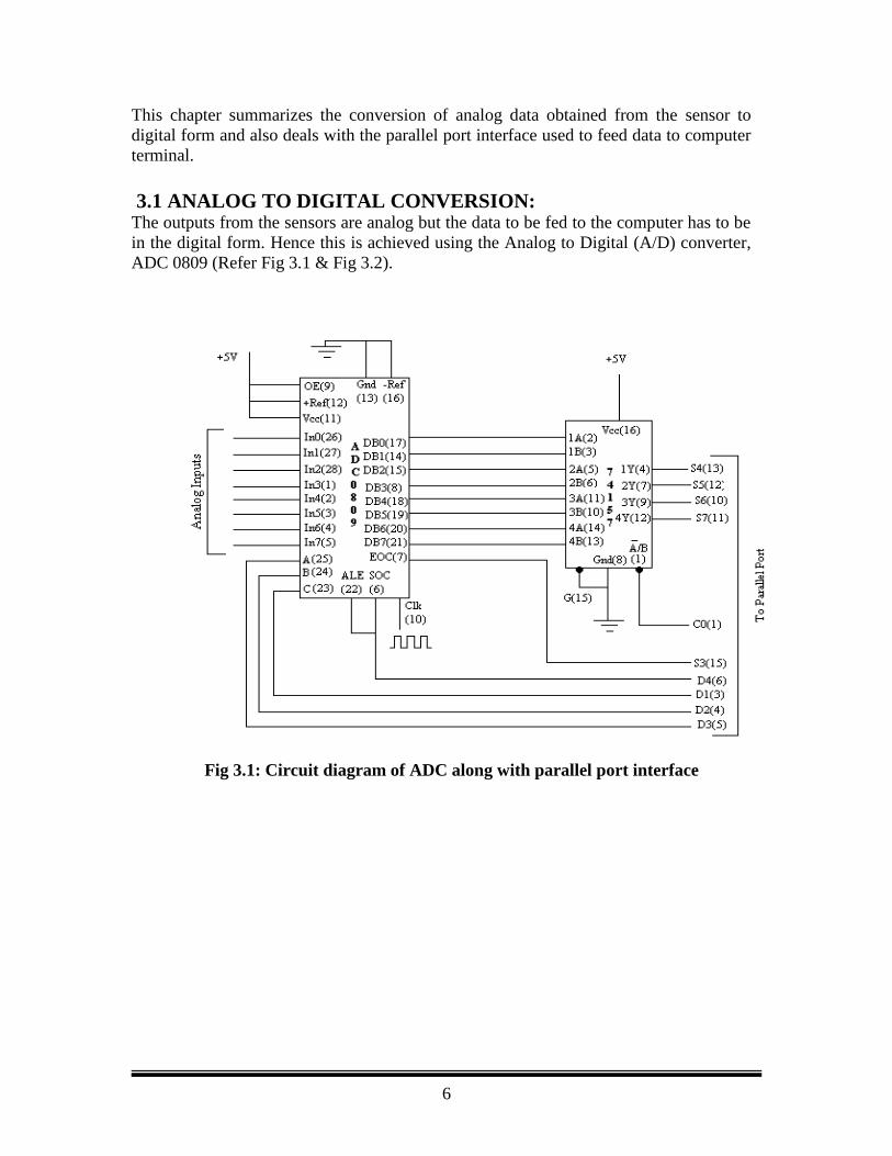
3.1 ANALOG TO DIGITAL CONVERSION: The outputs from the sensors are analog but the data to be fed to the computer has to be
in the digital form. Hence this is achieved using the Analog to Digital (A/D) converter,
ADC 0809 (Refer Fig 3.1 & Fig 3.2).
Fig 3.1: Circuit diagram of ADC along with parallel port interface
7
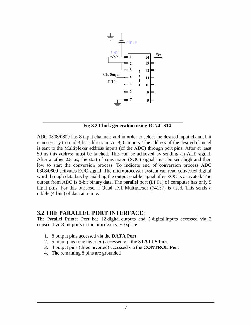
Fig 3.2 Clock generation using IC 74LS14
ADC 0808/0809 has 8 input channels and in order to select the desired input channel, it
is necessary to send 3-bit address on A, B, C inputs. The address of the desired channel
is sent to the Multiplexer address inputs (of the ADC) through port pins. After at least
50 ns this address must be latched. This can be achieved by sending an ALE signal.
After another 2.5 µs, the start of conversion (SOC) signal must be sent high and then
low to start the conversion process. To indicate end of conversion process ADC
0808/0809 activates EOC signal. The microprocessor system can read converted digital
word through data bus by enabling the output enable signal after EOC is activated. The
output from ADC is 8-bit binary data. The parallel port (LPT1) of computer has only 5
input pins. For this purpose, a Quad 2X1 Multiplexer (74157) is used. This sends a
nibble (4-bits) of data at a time.
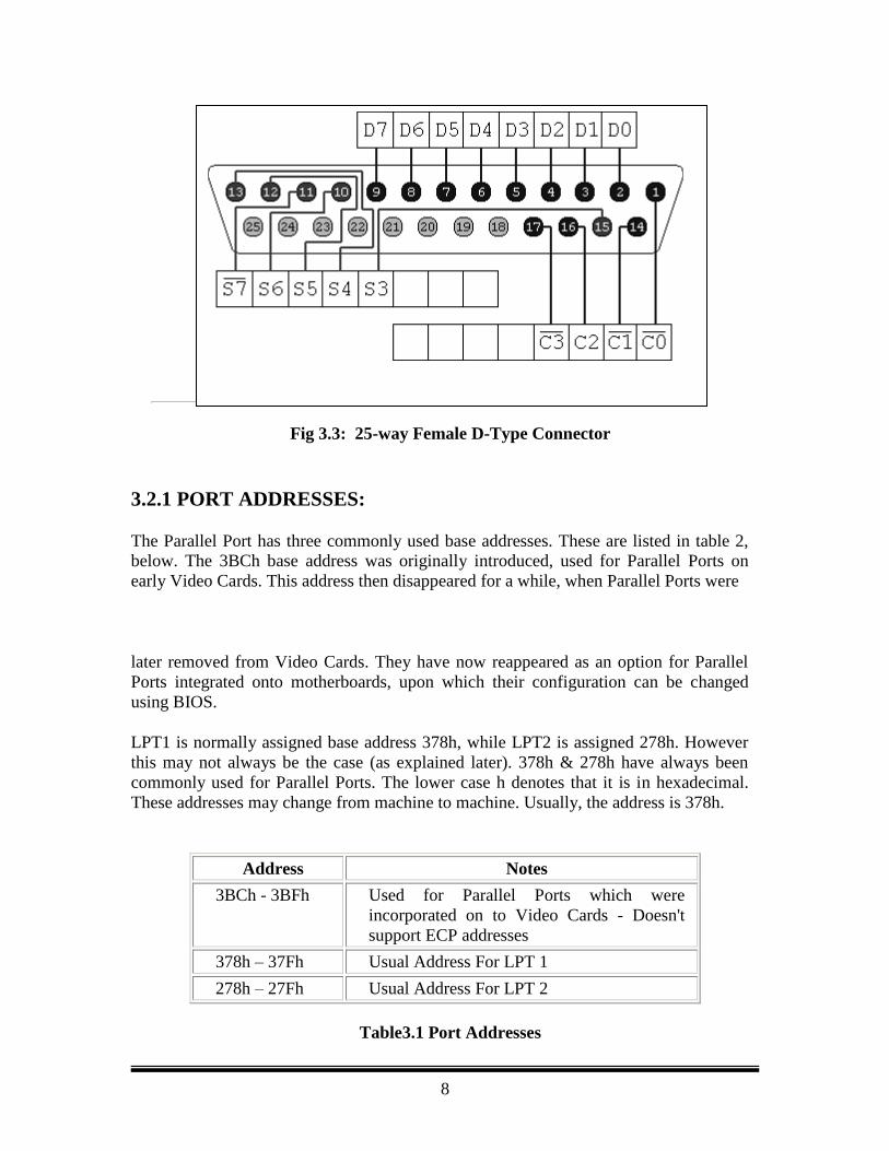
3.2 THE PARALLEL PORT INTERFACE: The Parallel Printer Port has 12 digital outputs and 5 digital inputs accessed via 3
consecutive 8-bit ports in the processor's I/O space.
1. 8 output pins accessed via the DATA Port
2. 5 input pins (one inverted) accessed via the STATUS Port
3. 4 output pins (three inverted) accessed via the CONTROL Port
4. The remaining 8 pins are grounded
8
Fig 3.3: 25-way Female D-Type Connector
3.2.1 PORT ADDRESSES:
The Parallel Port has three commonly used base addresses. These are listed in table 2,
below. The 3BCh base address was originally introduced, used for Parallel Ports on
early Video Cards. This address then disappeared for a while, when Parallel Ports were
later removed from Video Cards. They have now reappeared as an option for Parallel
Ports integrated onto motherboards, upon which their configuration can be changed
using BIOS.
LPT1 is normally assigned base address 378h, while LPT2 is assigned 278h. However
this may not always be the case (as explained later). 378h & 278h have always been
commonly used for Parallel Ports. The lower case h denotes that it is in hexadecimal.
These addresses may change from machine to machine. Usually, the address is 378h.
Address Notes
3BCh - 3BFh Used for Parallel Ports which were
incorporated on to Video Cards - Doesn't
support ECP addresses
378h – 37Fh Usual Address For LPT 1
278h – 27Fh Usual Address For LPT 2
Table3.1 Port Addresses
9
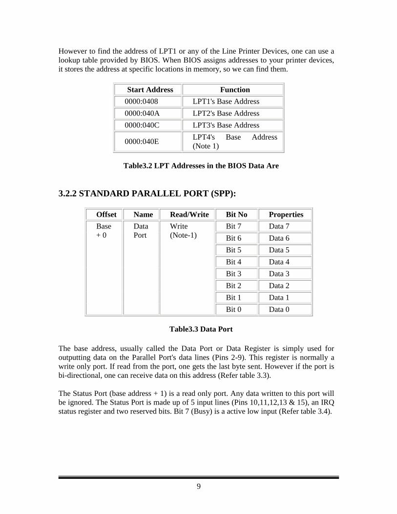
However to find the address of LPT1 or any of the Line Printer Devices, one can use a
lookup table provided by BIOS. When BIOS assigns addresses to your printer devices,
it stores the address at specific locations in memory, so we can find them.
Start Address Function
0000:0408 LPT1's Base Address
0000:040A LPT2's Base Address
0000:040C LPT3's Base Address
0000:040E LPT4's Base Address
(Note 1)
Table3.2 LPT Addresses in the BIOS Data Are
3.2.2 STANDARD PARALLEL PORT (SPP):
Offset Name Read/Write Bit No Properties
Base
+ 0
Data
Port
Write
(Note-1)
Bit 7 Data 7
Bit 6 Data 6
Bit 5 Data 5
Bit 4 Data 4
Bit 3 Data 3
Bit 2 Data 2
Bit 1 Data 1
Bit 0 Data 0
Table3.3 Data Port
The base address, usually called the Data Port or Data Register is simply used for
outputting data on the Parallel Port's data lines (Pins 2-9). This register is normally a
write only port. If read from the port, one gets the last byte sent. However if the port is
bi-directional, one can receive data on this address (Refer table 3.3).
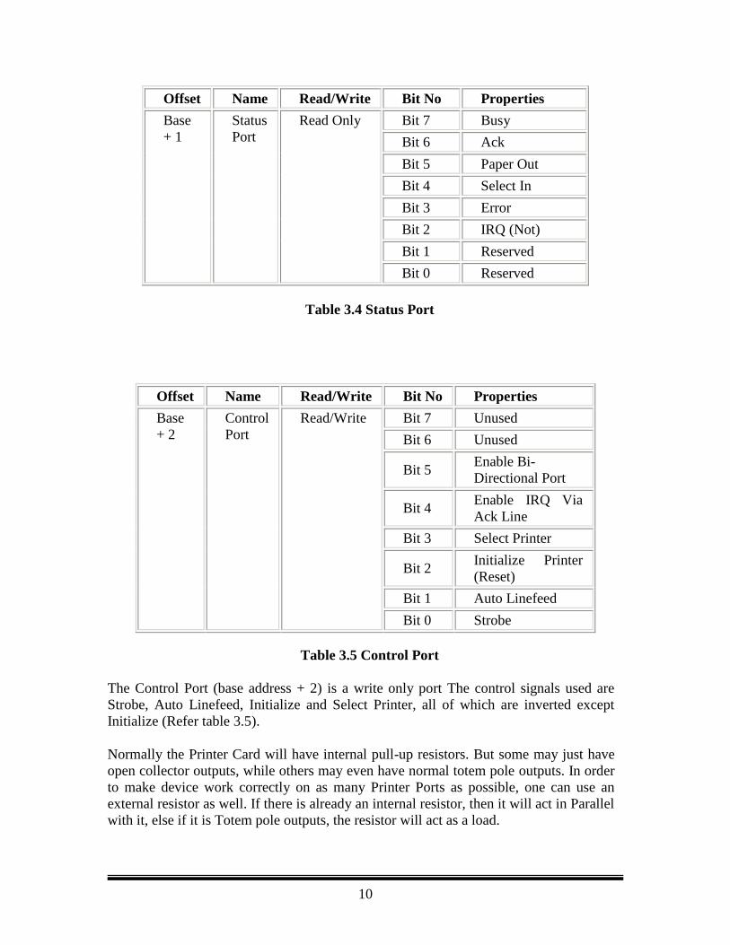
The Status Port (base address + 1) is a read only port. Any data written to this port will
be ignored. The Status Port is made up of 5 input lines (Pins 10,11,12,13 & 15), an IRQ
status register and two reserved bits. Bit 7 (Busy) is a active low input (Refer table 3.4).
10
Offset Name Read/Write Bit No Properties
Base
+ 1
Status
Port
Read Only Bit 7 Busy
Bit 6 Ack
Bit 5 Paper Out
Bit 4 Select In
Bit 3 Error
Bit 2 IRQ (Not)
Bit 1 Reserved
Bit 0 Reserved
Table 3.4 Status Port
Offset Name Read/Write Bit No Properties
Base
+ 2
Control
Port
Read/Write Bit 7 Unused
Bit 6 Unused
Bit 5 Enable Bi-
Directional Port
Bit 4 Enable IRQ Via
Ack Line
Bit 3 Select Printer
Bit 2 Initialize Printer
(Reset)
Bit 1 Auto Linefeed
Bit 0 Strobe
Table 3.5 Control Port
The Control Port (base address + 2) is a write only port The control signals used are
Strobe, Auto Linefeed, Initialize and Select Printer, all of which are inverted except
Initialize (Refer table 3.5).
Normally the Printer Card will have internal pull-up resistors. But some may just have
open collector outputs, while others may even have normal totem pole outputs. In order
to make device work correctly on as many Printer Ports as possible, one can use an
external resistor as well. If there is already an internal resistor, then it will act in Parallel
with it, else if it is Totem pole outputs, the resistor will act as a load.
11
Bits 4 & 5 are internal controls. Bit four will enable the IRQ and Bit 5 will enable the
bi-directional port meaning that one can input 8 bits using (DATA 0-7). This mode is
only possible if the card supports it. Bits 6 & 7 are reserved. Any writes to these two
bits will be ignored.
Some control ports are not open collector, but have totem pole outputs. Therefore, in the
interest of portability it is recommend inputting four bits at a time using Multiplexer,
reading a nibble at a time.
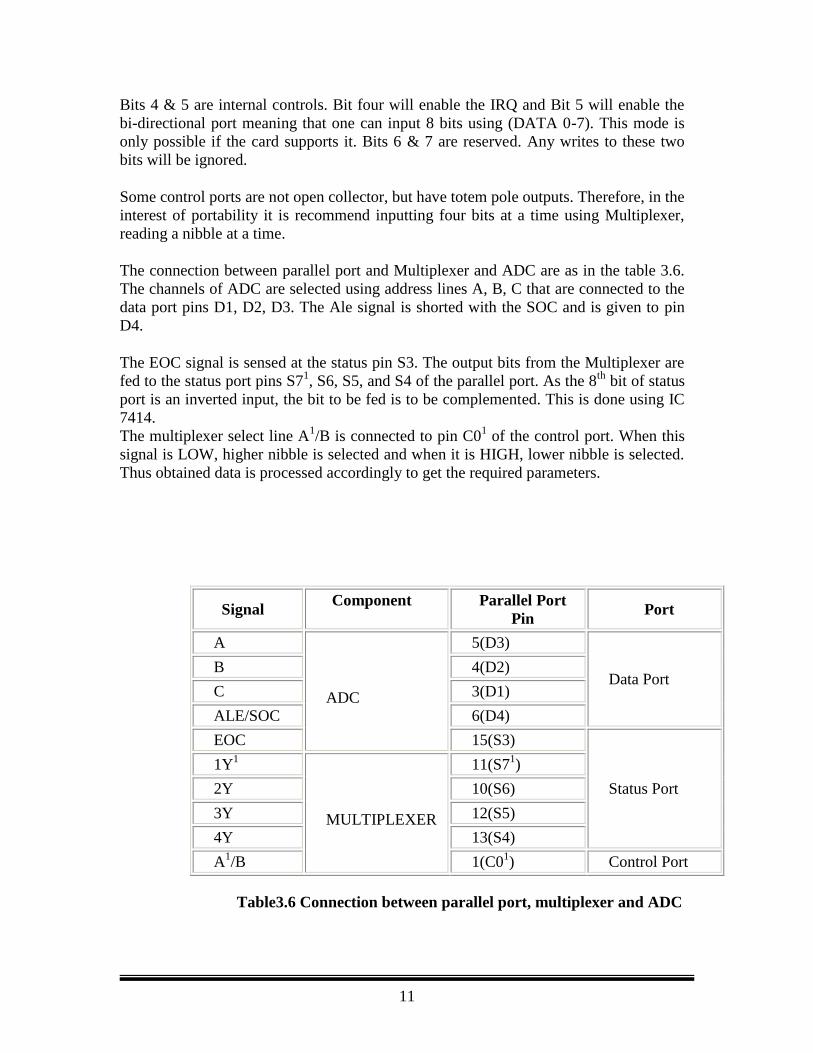
The connection between parallel port and Multiplexer and ADC are as in the table 3.6.
The channels of ADC are selected using address lines A, B, C that are connected to the
data port pins D1, D2, D3. The Ale signal is shorted with the SOC and is given to pin
D4.
The EOC signal is sensed at the status pin S3. The output bits from the Multiplexer are
fed to the status port pins S71, S6, S5, and S4 of the parallel port. As the 8
th bit of status
port is an inverted input, the bit to be fed is to be complemented. This is done using IC
7414.
The multiplexer select line A1/B is connected to pin C0
1 of the control port. When this
signal is LOW, higher nibble is selected and when it is HIGH, lower nibble is selected.
Thus obtained data is processed accordingly to get the required parameters.
Signal Component Parallel Port
Pin Port
A
ADC
5(D3)
Data Port B 4(D2)
C 3(D1)
ALE/SOC 6(D4)
EOC 15(S3)
Status Port
1Y1
MULTIPLEXER
11(S71)
2Y 10(S6)
3Y 12(S5)
4Y 13(S4)
A1/B 1(C0
1) Control Port
Table3.6 Connection between parallel port, multiplexer and ADC
12
3.2.3 PARALLEL PORT PROGRAMMING: The aim of the program is to send proper control signals to the ADC and the
Multiplexer and read the data from Status Port. It should also convert the data into
useful parameters.
As the useful data is in the higher nibble of the status port, to obtain the data the lower
nibble is truncated. The lower nibble from the Multiplexer also arrives at the higher
nibble of the status port. So it has to be right shifted 4 times to get the data in the lower
nibble. Both the nibbles thus obtained are clubbed to get complete 8-bit data. This data
is then converted into required parameter using proper conversion techniques. The
parameters are checked for safety limits. If they cross the specified limits, then an Alert
SMS is sent to the concerned doctor. A Routine SMS is also sent every 15 minutes even
though there is no alert. To send a parameter through SMS, it has to be converted into
proper PDU (Protocol Description Unit) format that is discussed in the following
sections.
4.1 THE GSM TECHNOLOGY:
The acronym GSM stands for Global System for Mobile telecommunications. The
digital nature of GSM allows data, both synchronous and asynchronous, to be
transported as a bearer service to or from an ISDN terminal. Data can use either the
transparent service, which has a fixed delay but no guarantee of data integrity, or a non-
transparent service, which guarantees data integrity through an Automatic Repeat
Request (ARQ) mechanism, but with a variable delay. The data rates supported by
GSM are 300 bps, 600 bps, 1200 bps, 2400 bps, and 9600 bps.
The most basic teleservice supported by GSM is telephony. There is an emergency
service, where the nearest emergency service provider is notified by dialing three
digits. Group 3 fax, an analog method described in ITUT recommendation T.30, is also
supported by use of an appropriate fax adaptor. A unique feature of GSM compared to
older analog systems is the Short Message Service (SMS). SMS is a bi-directional
service for sending short alphanumeric (up to 160 bytes) messages in a store and -
forward fashion. For point-to-point SMS, a message can be sent to another subscriber
to the service, and an acknowledgement of receipt is provided to the sender. SMS can
also be used in a cell broadcast mode, for sending messages such as traffic updates or
news updates. Messages can be stored in the SIM card for later retrieval.
Supplementary services are provided on top of teleservices or bearer services, and
include features such as caller identification, call forwarding, call waiting, multiparty
conversations, and barring of outgoing (international) calls, among others.
4.1.1 ARCHITECTURE OF THE GSM NETWORK:
13
A GSM network is composed of several functional entities, whose functions and
interfaces are defined. The GSM network can be divided into three broad parts. The
subscriber carries The Mobile Station; the Base Station Subsystem controls the
radio link with the Mobile Station. The Network Subsystem, the main part of which is
the Mobile services Switching Center, performs the switching of calls between the
mobile and other fixed or mobile network users, as well as management of mobile
services, such as authentication.
4.1.2 MOBILE STATION:
The mobile station (MS) consists of the physical equipment, such as the radio
transceiver, display and digital signal processors, and a smart card called the Subscriber
Identity Module (SIM).
4.1.3 BASE STATION SUBSYSTEM:
The Base Station Subsystem is composed of two parts, the Base Transceiver Station
(BTS) and the Base Station Controller (BSC). These communicate across the specified
Abis interface, allowing (as in the rest of the system) operation between components
made by different suppliers
4.1.4 NETWORK SUBSYSTEM:
The central component of the Network Subsystem is the Mobile services Switching
Center (MSC). It acts like a normal switching node of the PSTN or ISDN, and in
addition provides all the functionality needed to handle a mobile subscriber, such as
registration, authentication, location updating, handovers, and call routing to a roaming
subscriber. These services are provided in conjunction with several functional entities,
which together form the Network Subsystem. The MSC provides the connection to the
public fixed network (PSTN or ISDN), and signaling between functional entities uses
the ITUT Signaling System Number 7 (SS7), used in ISDN and widely used in current
public networks.
The mobile phones that can be connected to the computer are Siemens c35i, Nokia-
5000 series, Nokia-8000 series etc. The mobile phone used here is Siemens c35i. The
mobile is connected to the serial port (COM1) of computer through a data cable.
The GSM mobile telephone can be controlled using AT commands, where AT+C
commands according to ETSI GSM 07.07 and GSM 07.05 specification as well as
several manufacturer specific AT commands are available.
4.2 SMS AND THE PDU FORMAT:
Short Message Service (SMS) is the ability to send and receive short alphanumeric
messages to and from mobile telephones. SMS can also be used as a transport for binary
payloads and to implement the WAP stack on top of the SMSC bear. SMS was created
as part of the GSM Phase 1 standard. SMS allows users to directly transmit messages to
14
each other without the use of an operator (it is, however, necessary to have the
underlying operator controlled wireless service). The first user can send a message to a
mobile unit, via a direct connect computer. The SMS protocol of messaging is also
"smarter" then standard paging. SMS is a store and forward method therefore, if the end
user is not available, the mobile unit is powered off, or the unit is outside a service area,
when the unit comes back on line the message will appear. A SMS message can also be
sent "certified," where it will notify the message originator of the end user's receipt of
themessage. 4.2.1 THE PDU FORMAT: There are two ways of sending and receiving SMS messages:
1. Text mode
2. PDU (protocol description unit) mode.
The text mode (unavailable on some phones) is just an encoding of the bit stream
represented by the PDU mode. Alphabets may differ and there are several encoding
alternatives when displaying an SMS message. If one reads the message on phone, the
phone will choose a proper encoding. An application capable of reading incoming SMS
messages can thus use text mode or PDU mode. If text mode is used, the application is
bound to (or limited by) the set of preset encoding options. In some cases, that's just not
good enough. If PDU mode is used, any encoding can be implemented. Using Text
mode or PDU mode depends on the mobile on which one works. For e.g. Siemens c35i
works on PDU mode where as Nokia 5000 series works on Text mode. The mode of
operation cannot be changed i.e., text mode operations cannot be performed on a
Siemens set and vice versa.
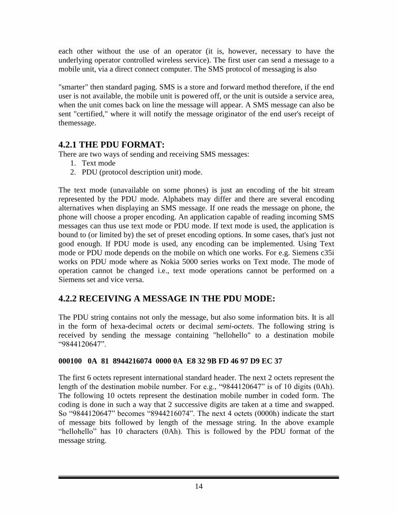
4.2.2 RECEIVING A MESSAGE IN THE PDU MODE:
The PDU string contains not only the message, but also some information bits. It is all
in the form of hexa-decimal octets or decimal semi-octets. The following string is
received by sending the message containing "hellohello" to a destination mobile
“9844120647”.
000100 0A 81 8944216074 0000 0A E8 32 9B FD 46 97 D9 EC 37
The first 6 octets represent international standard header. The next 2 octets represent the
length of the destination mobile number. For e.g., “9844120647” is of 10 digits (0Ah).
The following 10 octets represent the destination mobile number in coded form. The
coding is done in such a way that 2 successive digits are taken at a time and swapped.
So “9844120647” becomes “8944216074”. The next 4 octets (0000h) indicate the start
of message bits followed by length of the message string. In the above example
“hellohello” has 10 characters (0Ah). This is followed by the PDU format of the
message string.
15
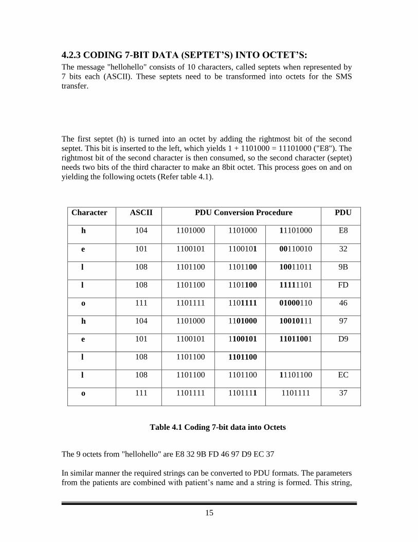
4.2.3 CODING 7-BIT DATA (SEPTET’S) INTO OCTET’S:
The message "hellohello" consists of 10 characters, called septets when represented by
7 bits each (ASCII). These septets need to be transformed into octets for the SMS
transfer.
The first septet (h) is turned into an octet by adding the rightmost bit of the second
septet. This bit is inserted to the left, which yields 1 + 1101000 = 11101000 ("E8"). The
rightmost bit of the second character is then consumed, so the second character (septet)
needs two bits of the third character to make an 8bit octet. This process goes on and on
yielding the following octets (Refer table 4.1).
Character ASCII PDU Conversion Procedure PDU
h 104 1101000 1101000 11101000 E8
e 101 1100101 1100101 00110010 32
l 108 1101100 1101100 10011011 9B
l 108 1101100 1101100 11111101 FD
o 111 1101111 1101111 01000110 46
h 104 1101000 1101000 10010111 97
e 101 1100101 1100101 11011001 D9
l 108 1101100 1101100
l 108 1101100 1101100 11101100 EC
o 111 1101111 1101111 1101111 37
Table 4.1 Coding 7-bit data into Octets
The 9 octets from "hellohello" are E8 32 9B FD 46 97 D9 EC 37
In similar manner the required strings can be converted to PDU formats. The parameters
from the patients are combined with patient‟s name and a string is formed. This string,
16
along with doctor‟s mobile phone number is sent as parameter to a function which does
the PDU format conversion. The converted string is sent through the COM1 port to
mobile phone. To send the PDU format string through the serial port, AT commands are
used. They are as follows:
AT+CMGS=21
> 0001000A81894421607400000AE8329BFD4697D9EC37 <ctrl-Z>+CMGS: 182
OK
AT specifies that the following is an AT command to the processor.
+CMGS is command to send message. This instruction has to be followed with the
length of PDU such that length= (full length – 2)/2. In this example full length is 44.
Therefore length is 21. This instruction has to be sent through the serial port. The
mobile phone then responds with a „>‟ sign. Once the response is received PDU string
has to be inserted. The PDU string has to be followed with a <ctrl-z> character to send
it to mobile phone. If the request is acknowledged and if the message is sent, the mobile
phone responds by sending the address of the memory location (+CMGS: 182) of SIM
where the outgoing message is stored and an “ok” to the computer else an “error” is
sent. The specifications of serial port are discussed in the next section.
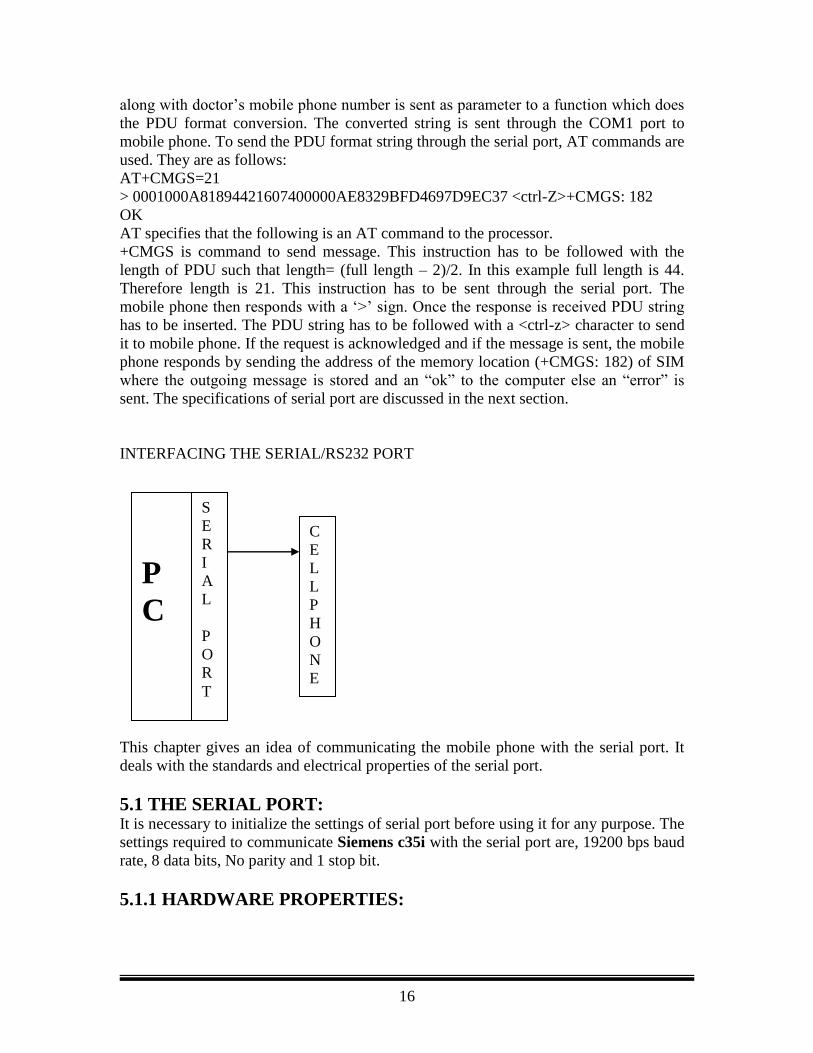
INTERFACING THE SERIAL/RS232 PORT
This chapter gives an idea of communicating the mobile phone with the serial port. It
deals with the standards and electrical properties of the serial port.
5.1 THE SERIAL PORT:
It is necessary to initialize the settings of serial port before using it for any purpose. The
settings required to communicate Siemens c35i with the serial port are, 19200 bps baud
rate, 8 data bits, No parity and 1 stop bit.
5.1.1 HARDWARE PROPERTIES:
P
C
S
E
R
I
A
L
P
O
R
T
C
E
L
L
P
H
O
N
E
17
Devices that use serial cables for their communication are split into two categories. These
are DCE (Data Communications Equipment) and DTE (Data Terminal Equipment.) Data
Communications Equipment are devices such as your modem, TA adapter, plotter etc
while Data Terminal Equipment is your Computer or Terminal.
The electrical specification of the serial port is contained in the EIA (Electronics Industry
Association) RS232C standard. It states many parameters such as -
1.
A "Space" (logic 0) will be between +3 and +25 Volts.
2. A "Mark" (Logic 1) will be between -3 and -25 Volts.
3. The region between +3 and -3 volts is undefined.
4. An open circuit voltage should never exceed 25 volts. (In
Reference to GND)
5. A short circuit current should not exceed 500mA. The driver
should be able to handle this without damage. (Take note of this
one!)
Table 5.1 Electrical Properties of RS232C
Line Capacitance, Maximum Baud Rates etc are also included. It is interesting to note
however, that the RS232C standard specifies a maximum baud rate of 20,000 bps !,
which is rather slow by today's standards.
Serial Ports come in two "sizes", There are the D-Type 25 pin connector and the D-Type
9 pin connector both of which are male on the back of the PC, thus you will require a
female connector on your device. Below is a table of pin connections for the 9 pin and 25
pin D-Type connectors.
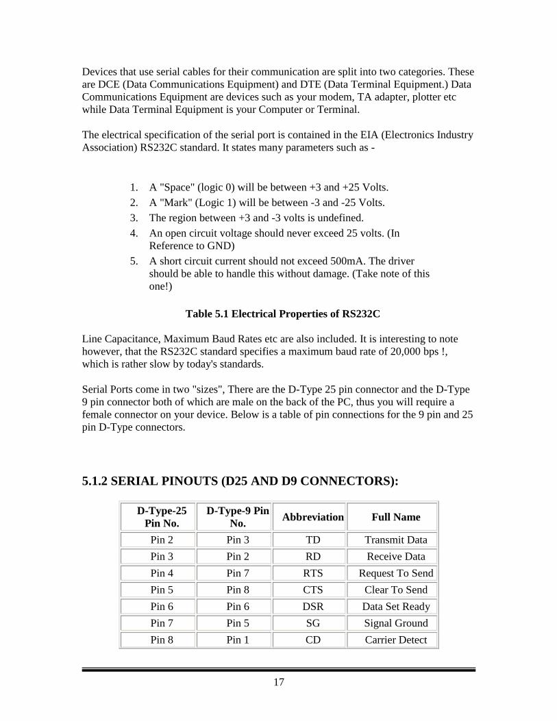
5.1.2 SERIAL PINOUTS (D25 AND D9 CONNECTORS):
D-Type-25
Pin No.
D-Type-9 Pin
No. Abbreviation Full Name
Pin 2 Pin 3 TD Transmit Data
Pin 3 Pin 2 RD Receive Data
Pin 4 Pin 7 RTS Request To Send
Pin 5 Pin 8 CTS Clear To Send
Pin 6 Pin 6 DSR Data Set Ready
Pin 7 Pin 5 SG Signal Ground
Pin 8 Pin 1 CD Carrier Detect
18
Pin 20 Pin 4 DTR Data Terminal
Ready
Pin 22 Pin 9 RI Ring Indicator
Table 5.2 D-Type 9 Pin and D Type 25 Pin Connectors
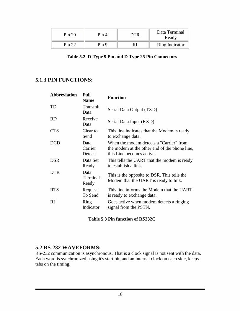
5.1.3 PIN FUNCTIONS:
Table 5.3 Pin function of RS232C
5.2 RS-232 WAVEFORMS: RS-232 communication is asynchronous. That is a clock signal is not sent with the data.
Each word is synchronized using it's start bit, and an internal clock on each side, keeps
tabs on the timing.
Abbreviation Full
Name Function
TD Transmit
Data Serial Data Output (TXD)
RD Receive
Data Serial Data Input (RXD)
CTS Clear to
Send
This line indicates that the Modem is ready
to exchange data.
DCD Data
Carrier
Detect
When the modem detects a "Carrier" from
the modem at the other end of the phone line,
this Line becomes active.
DSR Data Set
Ready
This tells the UART that the modem is ready
to establish a link.
DTR Data
Terminal
Ready
This is the opposite to DSR. This tells the
Modem that the UART is ready to link.
RTS Request
To Send
This line informs the Modem that the UART
is ready to exchange data.
RI Ring
Indicator
Goes active when modem detects a ringing
signal from the PSTN.
19
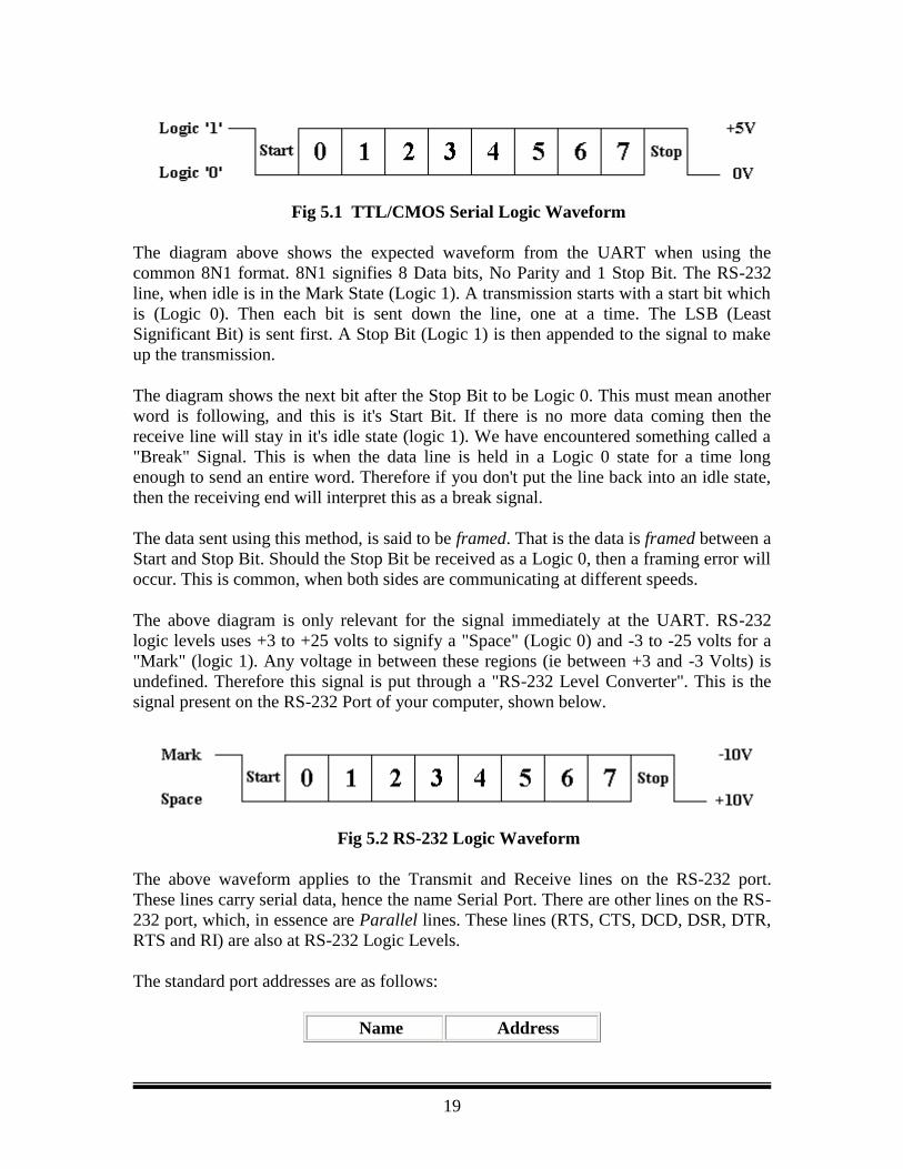
Fig 5.1 TTL/CMOS Serial Logic Waveform
The diagram above shows the expected waveform from the UART when using the
common 8N1 format. 8N1 signifies 8 Data bits, No Parity and 1 Stop Bit. The RS-232
line, when idle is in the Mark State (Logic 1). A transmission starts with a start bit which
is (Logic 0). Then each bit is sent down the line, one at a time. The LSB (Least
Significant Bit) is sent first. A Stop Bit (Logic 1) is then appended to the signal to make
up the transmission.
The diagram shows the next bit after the Stop Bit to be Logic 0. This must mean another
word is following, and this is it's Start Bit. If there is no more data coming then the
receive line will stay in it's idle state (logic 1). We have encountered something called a
"Break" Signal. This is when the data line is held in a Logic 0 state for a time long
enough to send an entire word. Therefore if you don't put the line back into an idle state,
then the receiving end will interpret this as a break signal.
The data sent using this method, is said to be framed. That is the data is framed between a
Start and Stop Bit. Should the Stop Bit be received as a Logic 0, then a framing error will
occur. This is common, when both sides are communicating at different speeds.
The above diagram is only relevant for the signal immediately at the UART. RS-232
logic levels uses +3 to +25 volts to signify a "Space" (Logic 0) and -3 to -25 volts for a
"Mark" (logic 1). Any voltage in between these regions (ie between +3 and -3 Volts) is
undefined. Therefore this signal is put through a "RS-232 Level Converter". This is the
signal present on the RS-232 Port of your computer, shown below.
Fig 5.2 RS-232 Logic Waveform
The above waveform applies to the Transmit and Receive lines on the RS-232 port.
These lines carry serial data, hence the name Serial Port. There are other lines on the RS-
232 port, which, in essence are Parallel lines. These lines (RTS, CTS, DCD, DSR, DTR,
RTS and RI) are also at RS-232 Logic Levels.
The standard port addresses are as follows:
Name Address
20
COM 1 3F8
COM 2 2F8
COM 3 3E8
COM 4 2E8
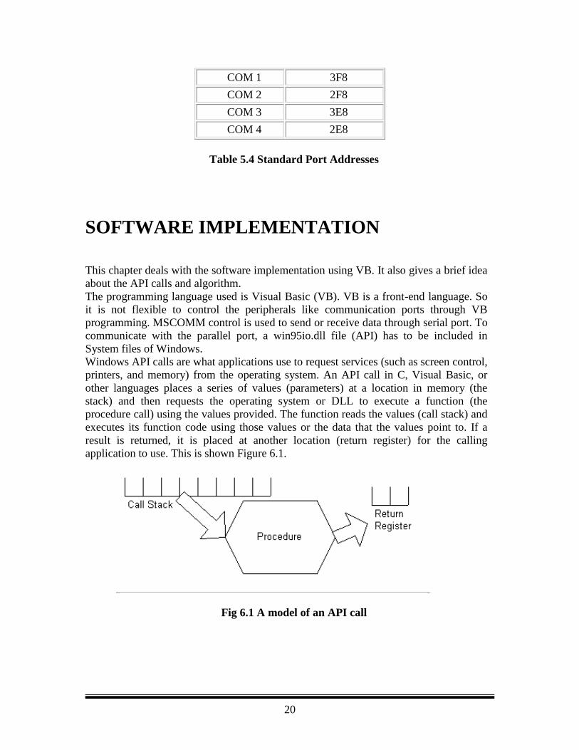
Table 5.4 Standard Port Addresses
SOFTWARE IMPLEMENTATION
This chapter deals with the software implementation using VB. It also gives a brief idea
about the API calls and algorithm.
The programming language used is Visual Basic (VB). VB is a front-end language. So
it is not flexible to control the peripherals like communication ports through VB
programming. MSCOMM control is used to send or receive data through serial port. To
communicate with the parallel port, a win95io.dll file (API) has to be included in
System files of Windows.
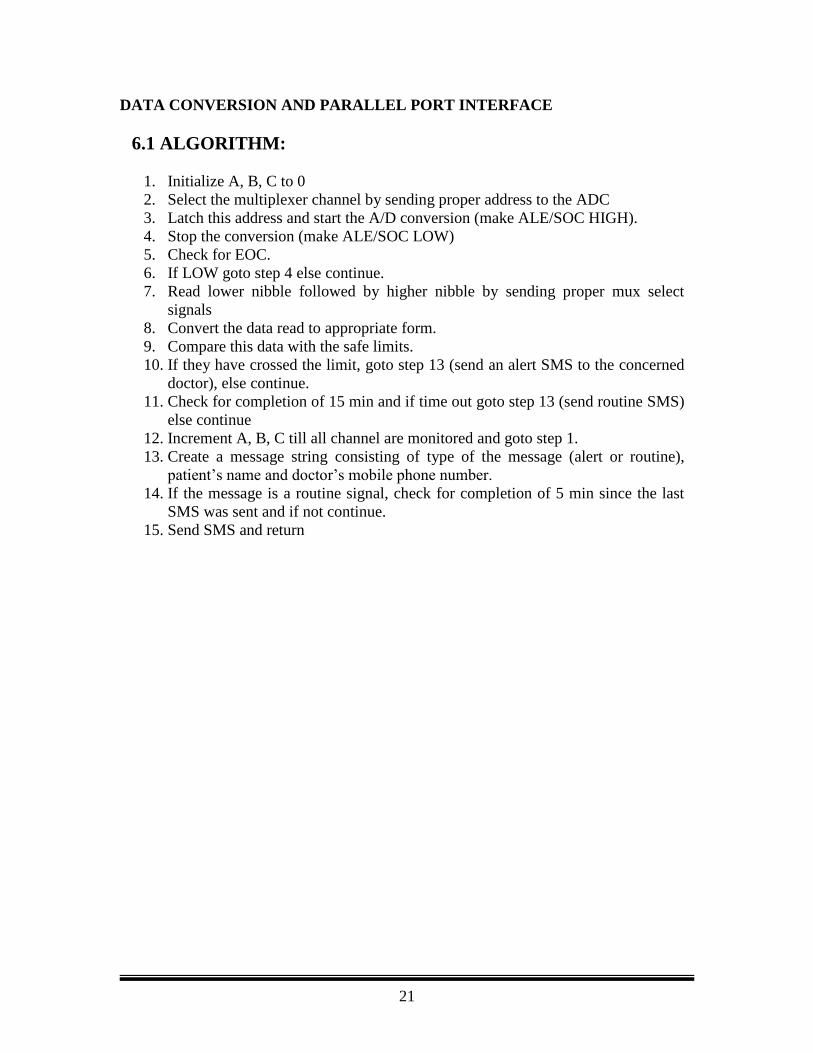
Windows API calls are what applications use to request services (such as screen control,
printers, and memory) from the operating system. An API call in C, Visual Basic, or
other languages places a series of values (parameters) at a location in memory (the
stack) and then requests the operating system or DLL to execute a function (the
procedure call) using the values provided. The function reads the values (call stack) and
executes its function code using those values or the data that the values point to. If a
result is returned, it is placed at another location (return register) for the calling
application to use. This is shown Figure 6.1.
Fig 6.1 A model of an API call
21
DATA CONVERSION AND PARALLEL PORT INTERFACE
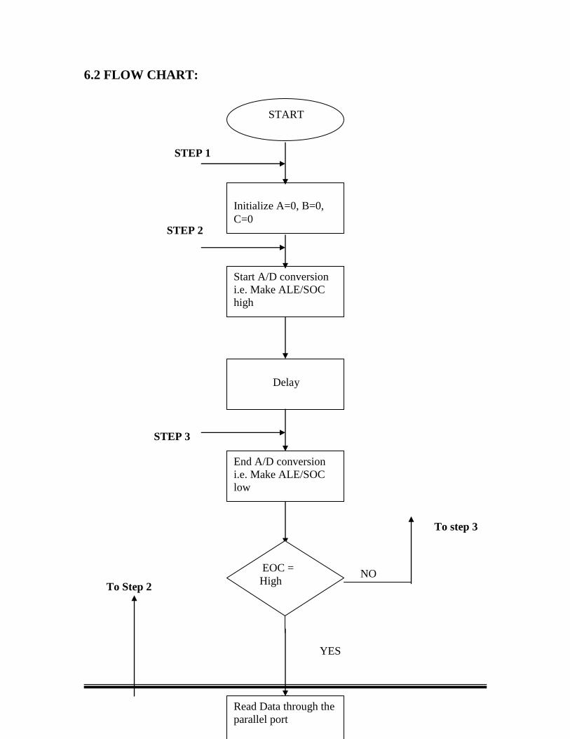
6.1 ALGORITHM:
1. Initialize A, B, C to 0
2. Select the multiplexer channel by sending proper address to the ADC
3. Latch this address and start the A/D conversion (make ALE/SOC HIGH).
4. Stop the conversion (make ALE/SOC LOW)
5. Check for EOC.
6. If LOW goto step 4 else continue.
7. Read lower nibble followed by higher nibble by sending proper mux select
signals
8. Convert the data read to appropriate form.
9. Compare this data with the safe limits.
10. If they have crossed the limit, goto step 13 (send an alert SMS to the concerned
doctor), else continue.
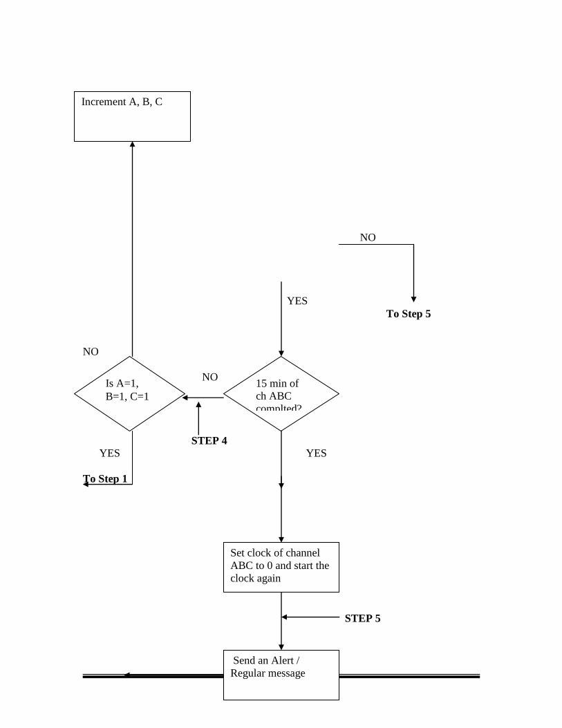
11. Check for completion of 15 min and if time out goto step 13 (send routine SMS)
else continue
12. Increment A, B, C till all channel are monitored and goto step 1.
13. Create a message string consisting of type of the message (alert or routine),
patient‟s name and doctor‟s mobile phone number.
14. If the message is a routine signal, check for completion of 5 min since the last
SMS was sent and if not continue.
15. Send SMS and return
22
6.2 FLOW CHART:
STEP 1
STEP 2
STEP 3
To step 3
NO
To Step 2
YES
START
Initialize A=0, B=0,
C=0
Start A/D conversion
i.e. Make ALE/SOC
high
Delay
End A/D conversion
i.e. Make ALE/SOC
low
Read Data through the
parallel port
EOC =
High
23
NO
YES
To Step 5
NO
NO
STEP 4
YES YES
To Step 1
STEP 5
15 min of
ch ABC
complted?
Is A=1,
B=1, C=1
Increment A, B, C
Set clock of channel
ABC to 0 and start the
clock again
Send an Alert /
Regular message
24
To Step 4
RESULTS AND DISCUSSION
7.1 RESULTS AND CONCLUSION: This system could successfully send Short Messaging Services (SMS) to the concerned
doctor‟s mobile phone as desired. The doctor could set the critical values for body
temperature and Heart rate for individual patients in the monitoring computer terminal.
The program was built to monitor two patients at a time and report the results to
concerned doctors.
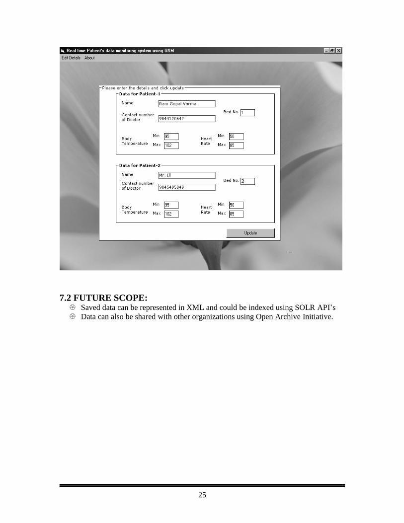
Fig. 7.1 Front end of Real time Patient’s data monitoring system
For the above entries if the temperature and heart rate of the two patients were within
the critical limits, a regular SMS was sent to the concerned doctor after every 15 min.
The SMS sent to doctor1 (9844120647) who is concerned with patient of bed no. 1
reads as: “The patient Ram Gopal Verma of bed no.: 1 has temperature 97.34 deg
Fahrenheit & Heart rate 74”.
If there is any change in temperature or heart rate above or below the critical values,
immediately an alert SMS is sent to the concerned doctor. An alert SMS repeats only
after every minute if the condition persists. It would look like this:
“ALERT, the patient Ram Gopal Verma of bed no.: 1 has temperature 103.69 deg
Fahrenheit & Heart rate 74”
This system is very helpful in large hospitals where the concerned doctor cannot be
with the patient all the time. It saves the doctor‟s valuable time by constantly
monitoring and sending real time parameter values to him at regular intervals of
time.
END
25
7.2 FUTURE SCOPE: Saved data can be represented in XML and could be indexed using SOLR API‟s
Data can also be shared with other organizations using Open Archive Initiative.
26
References
[1] Biomedical Digital Signal Processing by Willis J. Tompkins,1993
[2] Leslie Cromwell, Fred J. Weibell, Erich A. Pfeiffer, Biomedical Instrumentation
and Measurement; 2nd Edition 1980
[3] R S Khandpur. „Handbook of Biomedical Instrumentation.‟ TMH Publishing
Co Ltd, New Delhi.
[4] Ramakanth.A.Gayakawad:Op-amps & linear integrated circuits-PHI
[5] K R Botkar, “Integrated Cicuits”, Khanna Publishing 1994
[6] R. Devarakonda, G. Palanisamy, B.E. Wilson, and J.M. Green, “Mercury:
reusable metadata management data discovery and access system”, Earth Science
Informatics, vol. 3, 1: 87-94, May 2010.
[7] Andrew S. Tanenbaum, "Computer Networks", Tata Mcgraw Hill, 3rd Edition,
2001
[8] Devarakonda R., Palanisamy G., Green J., Wilson, B. E., “Mercury: Reusable
software application for Metadata Management Data Discovery and Access”, Eos
Trans. AGU 90(52), Fall Meet. Suppl.
[9] William C.Y. Lee, Mobile Cellular Telecommunications: Analog and Digital
Systems, 2nd edition, McGraw-Hill Professional, 1995
[10] R. Devarakonda, G. Palanisamy, J.M. Green, B.E. Wilson, “Data sharing and
retrieval using OAI-PMH”, Earth Science Informatics DOI: 10.1007/s12145-010-
0073-0, (2010)