Embed Size (px)
Citation preview
Software Tool for Fast and Optimized Stator Winding Design of Three-Phase Induction Motors
1. Short Description
In order to facilitate the (re)design process of the motor stator windings and to help repairers/rewinders improving the motor efficiency, a software tool was developed in 2004, named BobiSoft®. This software tool is very easy to use and integrates a unique computing algorithm that simplifies the original winding improvement or change process (Fig. 1). It helps the user to quickly, easily and accurately design an optimized motor winding, computing key stator winding parameters such as MMF space harmonics and total distortion, wire length, weight, resistance, conduction losses, magnetic flux, current density, etc.
Fig. 1. Computing algorithm to improve or change the original winding design.
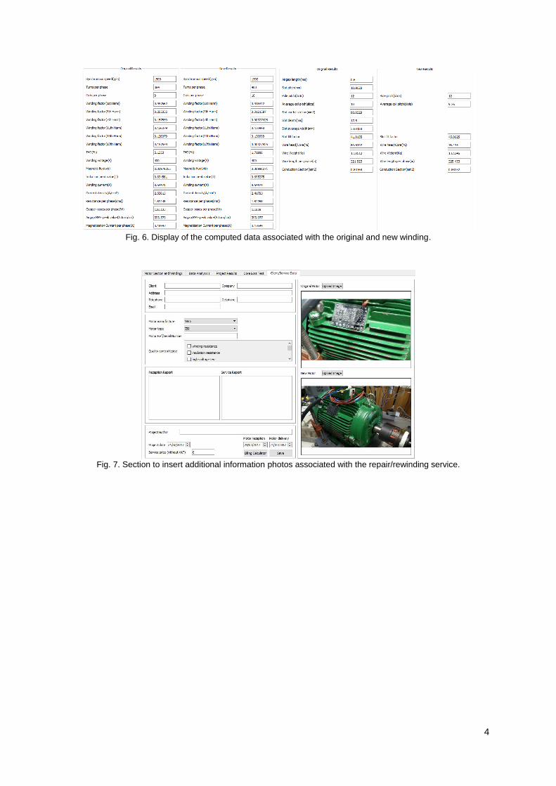
Basically, the user has to fill-up the original mechanical and electrical parameters of the motor (Fig. 2 and 3) and, after that, it will be able to change the original winding and check for the improvements in the Joule losses and spatial harmonic distortion of the air-gap MMF. After concluding the new design, the user can print the graphical (circular and planar) or numerical schemes of the coils (Fig. 4 and 5), which can then be printed out and used to help positioning correctly the coils in the stator. Key electrical and magnetic data is computed and presented immediately for both the original and new windings (Fig. 6). A section for additional information on the rewinding/repair service is also offered, in which some quality control information and photos can be saved (Fig. 7).
Design procedures that take hours can be done within a few minutes. Moreover, there is a section for the core loss test that performs all the required calculations. Each project/design can be saved as a separate file (*.bob; example attached), which can be attached to e-mails, facilitating the stator winding technical information/data exchange and organization/standardization, promoting an easier
2
and error-free data exchange between the professionals dealing with motor repair/rewinding tasks. The automatic reports are an excellent way to show to the clients of repair shops what was actually done in the service and to demonstrate the quality of the provided service.
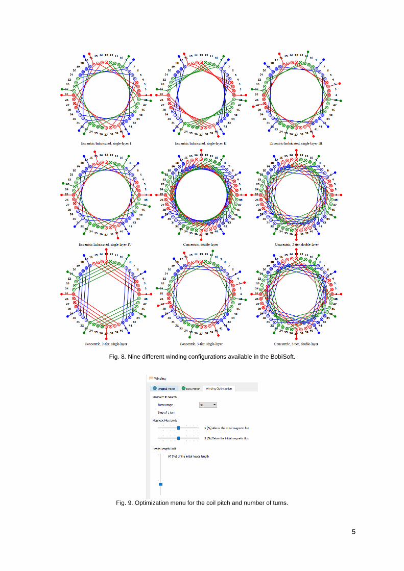
BobiSoft 2.0 (beta version under test) can handle windings for stator cores with up to 180 slots and offers 9 different automatically-generated winding types (Fig. 8), 6 single-layer and 3 double-layer windings, as well as fully-editable single- and double-layer windings, where the user is able to define the sides position and number of turns of each coil in each phase. It also allows to design two-phase windings for single-phase motors, as well as converting three-phase to two-phase windings and vice-versa.
This new version of BobiSoft offers extra and improved functionalities, namely, new and simpler user interface, 2D graphical representation of the stator core section, improved winding schemes (circular scheme has the orientation of the coil and planar scheme has the number of winding parallel groups along with their connection to the motor terminals and the heads are fully represented), improved design of the MMF in the airgap and free winding editor (where the user can customize the winding design, with variable number of turns per coil; fractional windings can also be implemented).
A new important feature of BobiSoft 2.0 is the automatic tool (Fig. 9) to determine the best coil pitch in double-layer windings and the best number of turns of each coil in concentric and eccentric/imbricated windings, maintaining, if desired, the product of the fundamental winding factor by the total phase turns constant (in order to avoid changing the fundamental flux).
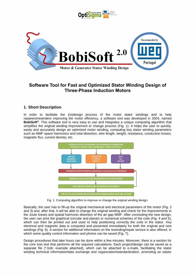
Fig. 2. Section to insert the stator data of the original and new motor/winding.
Fig. 3. Section to insert nameplate and mechanical data of the original and new motor.
3
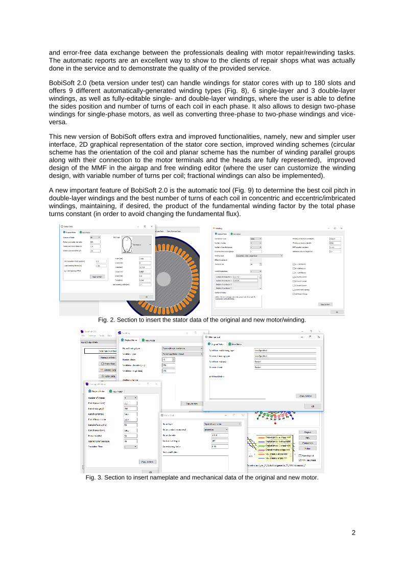
Fig. 4. Circular representation of the windings and of the MMF waveform.
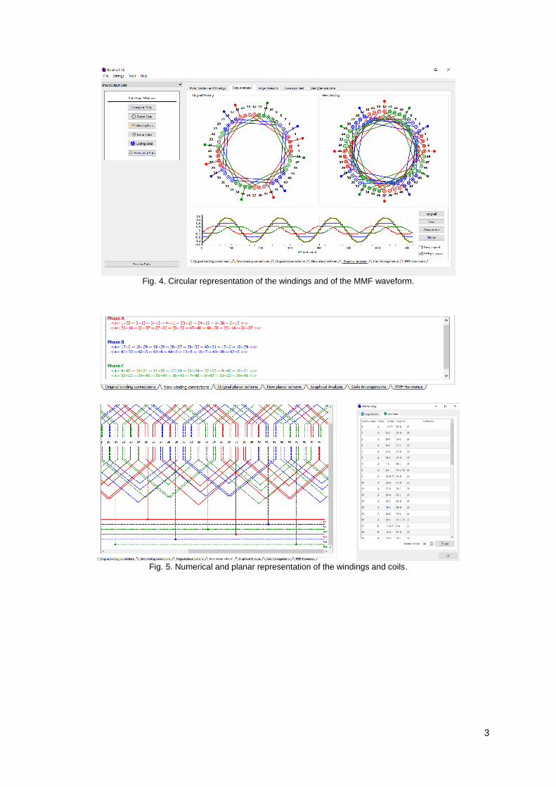
Fig. 5. Numerical and planar representation of the windings and coils.
4
Fig. 6. Display of the computed data associated with the original and new winding.
Fig. 7. Section to insert additional information photos associated with the repair/rewinding service.
5
Fig. 8. Nine different winding configurations available in the BobiSoft.
Fig. 9. Optimization menu for the coil pitch and number of turns.
6
2. Application Examples
In this section, some stator winding optimization examples are presented.
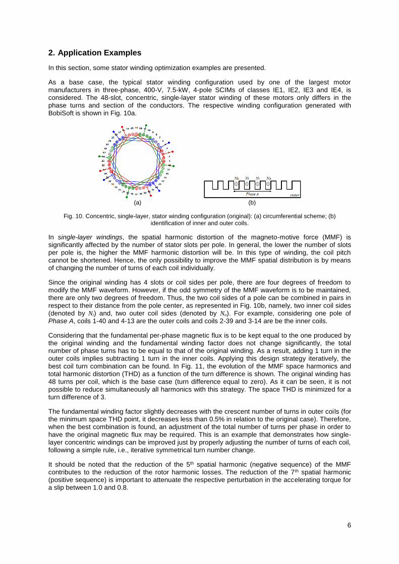
As a base case, the typical stator winding configuration used by one of the largest motor manufacturers in three-phase, 400-V, 7.5-kW, 4-pole SCIMs of classes IE1, IE2, IE3 and IE4, is considered. The 48-slot, concentric, single-layer stator winding of these motors only differs in the phase turns and section of the conductors. The respective winding configuration generated with BobiSoft is shown in Fig. 10a.
(a) (b)
Fig. 10. Concentric, single-layer, stator winding configuration (original): (a) circumferential scheme; (b) identification of inner and outer coils.
In single-layer windings, the spatial harmonic distortion of the magneto-motive force (MMF) is significantly affected by the number of stator slots per pole. In general, the lower the number of slots per pole is, the higher the MMF harmonic distortion will be. In this type of winding, the coil pitch cannot be shortened. Hence, the only possibility to improve the MMF spatial distribution is by means of changing the number of turns of each coil individually.
Since the original winding has 4 slots or coil sides per pole, there are four degrees of freedom to modify the MMF waveform. However, if the odd symmetry of the MMF waveform is to be maintained, there are only two degrees of freedom. Thus, the two coil sides of a pole can be combined in pairs in respect to their distance from the pole center, as represented in Fig. 10b, namely, two inner coil sides (denoted by Ni) and, two outer coil sides (denoted by No). For example, considering one pole of Phase A, coils 1-40 and 4-13 are the outer coils and coils 2-39 and 3-14 are be the inner coils.
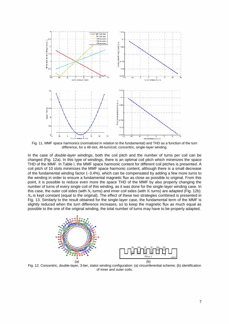
Considering that the fundamental per-phase magnetic flux is to be kept equal to the one produced by the original winding and the fundamental winding factor does not change significantly, the total number of phase turns has to be equal to that of the original winding. As a result, adding 1 turn in the outer coils implies subtracting 1 turn in the inner coils. Applying this design strategy iteratively, the best coil turn combination can be found. In Fig. 11, the evolution of the MMF space harmonics and total harmonic distortion (THD) as a function of the turn difference is shown. The original winding has 48 turns per coil, which is the base case (turn difference equal to zero). As it can be seen, it is not possible to reduce simultaneously all harmonics with this strategy. The space THD is minimized for a turn difference of 3.
The fundamental winding factor slightly decreases with the crescent number of turns in outer coils (for the minimum space THD point, it decreases less than 0.5% in relation to the original case). Therefore, when the best combination is found, an adjustment of the total number of turns per phase in order to have the original magnetic flux may be required. This is an example that demonstrates how single-layer concentric windings can be improved just by properly adjusting the number of turns of each coil, following a simple rule, i.e., iterative symmetrical turn number change.
It should be noted that the reduction of the 5th spatial harmonic (negative sequence) of the MMF contributes to the reduction of the rotor harmonic losses. The reduction of the 7th spatial harmonic (positive sequence) is important to attenuate the respective perturbation in the accelerating torque for a slip between 1.0 and 0.8.
7
Fig. 11. MMF space harmonics (normalized in relation to the fundamental) and THD as a function of the turn
difference, for a 48-slot, 48-turn/coil, concentric, single-layer winding.
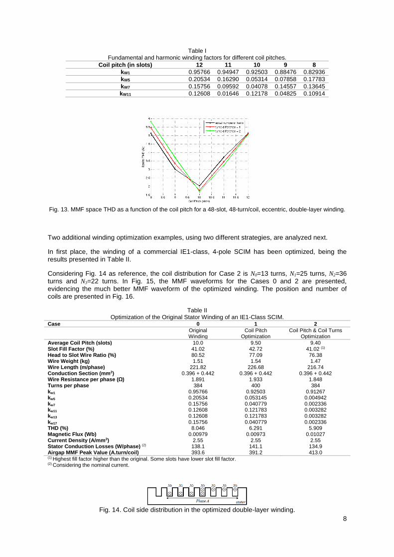
In the case of double-layer windings, both the coil pitch and the number of turns per coil can be changed (Fig. 12a). In this type of windings, there is an optimal coil pitch which minimizes the space THD of the MMF. In Table I, the MMF space harmonic content for different coil pitches is presented. A coil pitch of 10 slots minimizes the MMF space harmonic content, although there is a small decrease
of the fundamental winding factor (3.4%), which can be compensated by adding a few more turns to the winding in order to ensure a fundamental magnetic flux as close as possible to original. From this point, it is possible to reduce even more the space THD of the MMF by also properly changing the number of turns of every single coil of this winding, as it was done for the single-layer winding case. In this case, the outer coil sides (with No turns) and inner coil sides (with Ni turns) are adapted (Fig. 12b). Nm is kept constant (equal to the original). The effect of these two strategies combined is presented in Fig. 13. Similarly to the result obtained for the single-layer case, the fundamental term of the MMF is slightly reduced when the turn difference increases, so to keep the magnetic flux as much equal as possible to the one of the original winding, the total number of turns may have to be properly adapted.
(a) (b)
Fig. 12. Concentric, double-layer, 3-tier, stator winding configuration: (a) circumferential scheme; (b) identification of inner and outer coils.
8
Table I Fundamental and harmonic winding factors for different coil pitches.
Coil pitch (in slots) 12 11 10 9 8
kW1 0.95766 0.94947 0.92503 0.88476 0.82936
kW5 0.20534 0.16290 0.05314 0.07858 0.17783
kW7 0.15756 0.09592 0.04078 0.14557 0.13645
kW11 0.12608 0.01646 0.12178 0.04825 0.10914
Fig. 13. MMF space THD as a function of the coil pitch for a 48-slot, 48-turn/coil, eccentric, double-layer winding.
Two additional winding optimization examples, using two different strategies, are analyzed next.
In first place, the winding of a commercial IE1-class, 4-pole SCIM has been optimized, being the results presented in Table II.
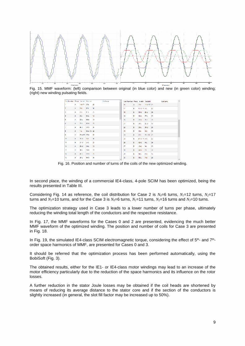
Considering Fig. 14 as reference, the coil distribution for Case 2 is N0=13 turns, N1=25 turns, N2=36 turns and N3=22 turns. In Fig. 15, the MMF waveforms for the Cases 0 and 2 are presented, evidencing the much better MMF waveform of the optimized winding. The position and number of coils are presented in Fig. 16.
Table II Optimization of the Original Stator Winding of an IE1-Class SCIM.
Case 0 1 2
Original Winding
Coil Pitch Optimization
Coil Pitch & Coil Turns Optimization
Average Coil Pitch (slots) 10.0 9.50 9.40 Slot Fill Factor (%) 41.02 42.72 41.02 (1) Head to Slot Wire Ratio (%) 80.52 77.09 76.38 Wire Weight (kg) 1.51 1.54 1.47 Wire Length (m/phase) 221.82 226.68 216.74 Conduction Section (mm2) 0.396 + 0.442 0.396 + 0.442 0.396 + 0.442 Wire Resistance per phase (Ω) 1.891 1.933 1.848 Turns per phase 384 400 384 kw1 0.95766 0.92503 0.91267 kw5 0.20534 0.053145 0.004942 kw7 0.15756 0.040779 0.002336 kw11 0.12608 0.121783 0.003282 kw13 0.12608 0.121783 0.003282 kw17 0.15756 0.040779 0.002336 THD (%) 8.046 6.291 5.909 Magnetic Flux (Wb) 0.00979 0.00973 0.01027 Current Density (A/mm2) 2.55 2.55 2.55 Stator Conduction Losses (W/phase) (2) 138.1 141.1 134.9 Airgap MMF Peak Value (A.turn/coil) 393.6 391.2 413.0 (1) Highest fill factor higher than the original. Some slots have lower slot fill factor. (2) Considering the nominal current.
Fig. 14. Coil side distribution in the optimized double-layer winding.
9
Fig. 15. MMF waveform: (left) comparison between original (in blue color) and new (in green color) winding; (right) new winding pulsating fields.
Fig. 16. Position and number of turns of the coils of the new optimized winding.
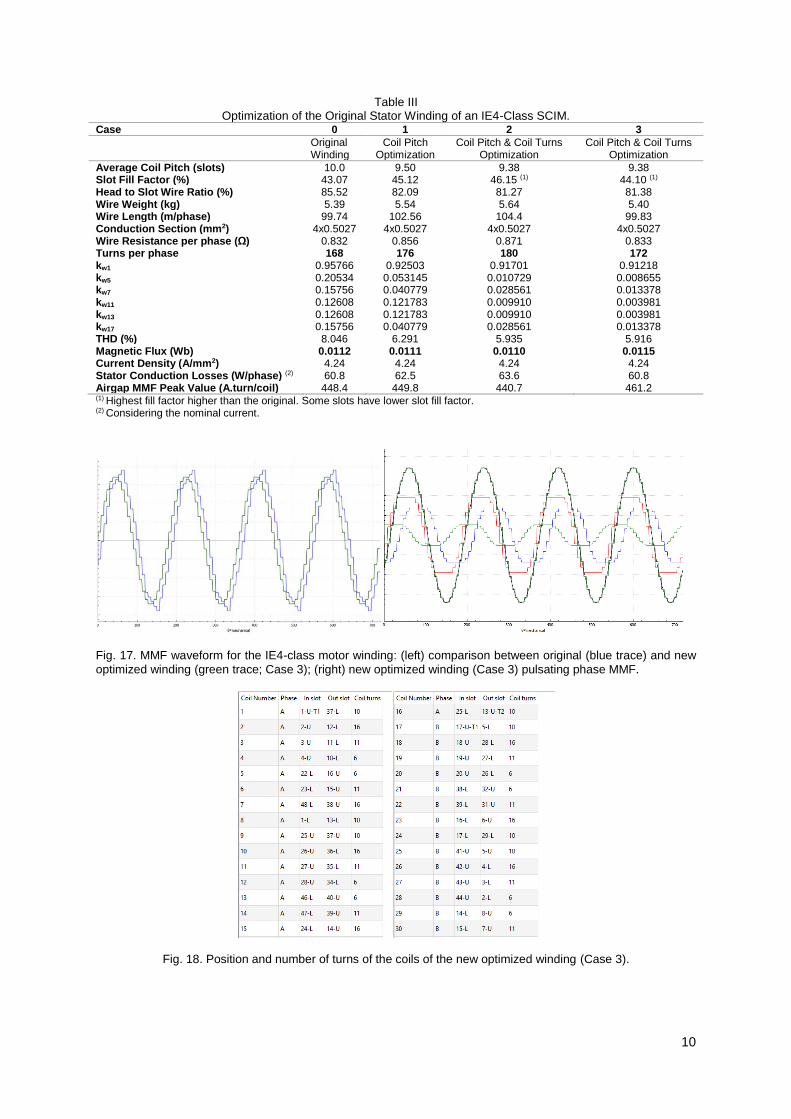
In second place, the winding of a commercial IE4-class, 4-pole SCIM has been optimized, being the results presented in Table III.
Considering Fig. 14 as reference, the coil distribution for Case 2 is N0=6 turns, N1=12 turns, N2=17 turns and N3=10 turns, and for the Case 3 is N0=6 turns, N1=11 turns, N2=16 turns and N3=10 turns.
The optimization strategy used in Case 3 leads to a lower number of turns per phase, ultimately reducing the winding total length of the conductors and the respective resistance.
In Fig. 17, the MMF waveforms for the Cases 0 and 2 are presented, evidencing the much better MMF waveform of the optimized winding. The position and number of coils for Case 3 are presented in Fig. 18.
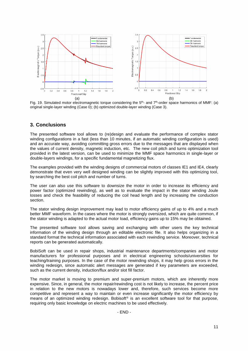
In Fig. 19, the simulated IE4-class SCIM electromagnetic torque, considering the effect of 5th- and 7th-order space harmonics of MMF, are presented for Cases 0 and 3.
It should be referred that the optimization process has been performed automatically, using the BobiSoft (Fig. 3).
The obtained results, either for the IE1- or IE4-class motor windings may lead to an increase of the motor efficiency particularly due to the reduction of the space harmonics and its influence on the rotor losses.
A further reduction in the stator Joule losses may be obtained if the coil heads are shortened by means of reducing its average distance to the stator core and if the section of the conductors is slightly increased (in general, the slot fill factor may be increased up to 50%).
10
Table III Optimization of the Original Stator Winding of an IE4-Class SCIM.
Case 0 1 2 3
Original Winding
Coil Pitch Optimization
Coil Pitch & Coil Turns Optimization
Coil Pitch & Coil Turns Optimization
Average Coil Pitch (slots) 10.0 9.50 9.38 9.38 Slot Fill Factor (%) 43.07 45.12 46.15 (1) 44.10 (1) Head to Slot Wire Ratio (%) 85.52 82.09 81.27 81.38 Wire Weight (kg) 5.39 5.54 5.64 5.40 Wire Length (m/phase) 99.74 102.56 104.4 99.83 Conduction Section (mm2) 4x0.5027 4x0.5027 4x0.5027 4x0.5027 Wire Resistance per phase (Ω) 0.832 0.856 0.871 0.833 Turns per phase 168 176 180 172 kw1 0.95766 0.92503 0.91701 0.91218 kw5 0.20534 0.053145 0.010729 0.008655 kw7 0.15756 0.040779 0.028561 0.013378 kw11 0.12608 0.121783 0.009910 0.003981 kw13 0.12608 0.121783 0.009910 0.003981 kw17 0.15756 0.040779 0.028561 0.013378 THD (%) 8.046 6.291 5.935 5.916 Magnetic Flux (Wb) 0.0112 0.0111 0.0110 0.0115 Current Density (A/mm2) 4.24 4.24 4.24 4.24 Stator Conduction Losses (W/phase) (2) 60.8 62.5 63.6 60.8 Airgap MMF Peak Value (A.turn/coil) 448.4 449.8 440.7 461.2 (1) Highest fill factor higher than the original. Some slots have lower slot fill factor. (2) Considering the nominal current.
Fig. 17. MMF waveform for the IE4-class motor winding: (left) comparison between original (blue trace) and new
optimized winding (green trace; Case 3); (right) new optimized winding (Case 3) pulsating phase MMF.
Fig. 18. Position and number of turns of the coils of the new optimized winding (Case 3).
11
(a) (b) Fig. 19. Simulated motor electromagnetic torque considering the 5th- and 7th-order space harmonics of MMF: (a) original single-layer winding (Case 0); (b) optimized double-layer winding (Case 3).
3. Conclusions
The presented software tool allows to (re)design and evaluate the performance of complex stator winding configurations in a fast (less than 10 minutes, if an automatic winding configuration is used) and an accurate way, avoiding committing gross errors due to the messages that are displayed when the values of current density, magnetic induction, etc. The new coil pitch and turns optimization tool provided in the latest version, can be used to minimize the MMF space harmonics in single-layer or double-layers windings, for a specific fundamental magnetizing flux.
The examples provided with the winding designs of commercial motors of classes IE1 and IE4, clearly demonstrate that even very well designed winding can be slightly improved with this optimizing tool, by searching the best coil pitch and number of turns.
The user can also use this software to downsize the motor in order to increase its efficiency and power factor (optimized rewinding), as well as to evaluate the impact in the stator winding Joule losses and check the feasibility of reducing the coil head length and by increasing the conduction section.
The stator winding design improvement may lead to motor efficiency gains of up to 4% and a much better MMF waveform. In the cases where the motor is strongly oversized, which are quite common, if the stator winding is adapted to the actual motor load, efficiency gains up to 15% may be obtained.
The presented software tool allows saving and exchanging with other users the key technical information of the winding design through an editable electronic file. It also helps organizing in a standard format the technical information associated with each rewinding service. Moreover, technical reports can be generated automatically.
BobiSoft can be used in repair shops, industrial maintenance departments/companies and motor manufacturers for professional purposes and in electrical engineering schools/universities for teaching/training purposes. In the case of the motor rewinding shops, it may help gross errors in the winding redesign, since automatic alert messages are generated if key parameters are exceeded, such as the current density, induction/flux and/or slot fill factor.
The motor market is moving to premium and super-premium motors, which are inherently more expensive. Since, in general, the motor repair/rewinding cost is not likely to increase, the percent price in relation to the new motors is nowadays lower and, therefore, such services become more competitive and represent a way to maintain or even increase significantly the motor efficiency by means of an optimized winding redesign. Bobisoft® is an excellent software tool for that purpose, requiring only basic knowledge on electric machines to be used effectively.
- END -


![Untitled-1 [] · Run Capacitor Stator Winding Relay Rotary Switch Rotor Start capacitor Main or Run Windin Stator Winding Main Winding Start capacitor Rotor](https://img.pdfslide.net/doc/110x75/5fc791720420d159865384b0/untitled-1-run-capacitor-stator-winding-relay-rotary-switch-rotor-start-capacitor.jpg)
![Stator Laminated stator · · 2016-11-16Winding hotspot Average winding Lowest winding Magnet Stator back iron Housing 0 1800 3600 5400 7200 9000 20 40 60 80 100 120 140 Time [secs]]](https://img.pdfslide.net/doc/110x75/5b04e5c37f8b9a6c0b8e6eee/stator-laminated-stator-hotspot-average-winding-lowest-winding-magnet-stator-back.jpg)