Embed Size (px)
Citation preview
GAS FORM-Cbased on the
OCIMF / SIGTTOSHIP INFORMATION QUESTIONNAIRE
forGAS CARRIERS
2nd Edition 1998
Specifications of the vessel and the gas installations are believedto be correct, but not guaranteed.
Gas Form-C Page 0
INDEX
GENERAL INFORMATION PAGE
A1 Principal Ship Particulars 2
A2 Hull Dimensions 4
A3 Immersion 4
A4 Loaded Particulars 4-5
A5 Parallel Mid-Body Dimensions 6
A6 Bunker Specifications and Capacities 6
A7 Fuel Consumption Details 6
A7 Speed/Consumption (Appendix) 7
A8 Main Engine Particulars 7
A9 Auxiliary Plants 7
A10 Power/Speed Information 7
A11 Thrusters 7
A12 Fresh Water 7
A13 Ballast Capacities and Pumps 8
A14 Mooring Equipment 8
A15 Navigational Equipment 10
A16 Communication and Electronics 12
CARGO SYSTEMSB1 Cargo - General Information 12
B2 Cargo Tanks 12
B3 Cargo Tank Capacities 13
B16 Deck Tank Capacities 17
B4 Loading Rates 17
B5 Discharging - General 19
B6 Discharge Performance 19
B7 Unpumpables 19
B8 Vaporising Unpumpables 19
B9 Reliquefaction Plant 20
B10 Section not in use.B11 Cargo Temperature Lowering Capability 20
B12 Inert Gas and Nitrogen 20
B13 Cargo Tank Inerting / De-Inerting 21
B14 Gas Freeing to Fresh Air 21B14 Gas Freeing to Fresh Air 21
B15 Changing Cargo Grades 21
B17 Pre-Loading Cooldown 22
B18 Vaporiser 22
B19 Blower 22
B20 Cargo Re-Heater 23
B21 Hydrate Control 23
B22 Cargo Measurement 23
B23 Cargo Sampling 24
B24 Cargo Manifold 25
B25 Cargo Manifold Reducers 27
B26 Connections to Shore for ESD and Communication Systems 27
B27 Manifold Derrick/Crane 27
B28 Stores Derrick/Crane 27
B29 Sister Vessel(s) 27
Gas Form-C Page 1
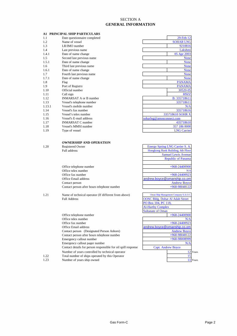
SECTION AGENERAL INFORMATION
A1 PRINCIPAL SHIP PARTICULARS1.1 Date questionnaire completed 29-Feb-121.2 Name of vessel SOHAR LNG1.3 LR/IMO number 92108161.4 Last previous name Lakshmi1.4.1 Date of name change 05 Apr 20031.5 Second last previous name None1.5.1 Date of name change None1.6 Third last previous name None1.6.1 Date of name change None1.7 Fourth last previous name None1.7.1 Date of name change None1.8 Flag PANAMA1.9 Port of Registry PANAMA1.10 Official number 30520-051.11 Call sign H9ZZ1.12 INMARSAT A or B number B: 3357186111.13 Vessel's telephone number 3357186111.13.1 Vessel's mobile number N/A1.14 Vessel's fax number 3357186161.15 Vessel’s telex number 335718610 SOHR X1.16 Vessel's E-mail address [email protected] INMARSAT C number 4357186101.18 Vessel's MMSI number 357 186 00001.19 Type of vessel LNG Carrier
OWNERSHIP AND OPERATION1.20 Registered Owner Energy Spring LNG Carrier S. A.
Full address Hongkong Bank Buliding, 6th Floor
Samuel Lewis AvenueRepublic of Panama
Office telephone number +968-24400900Office telex number N/A
Office fax number +968-24400923Office Email addressContact person Andrew BoyceContact person after hours telephone number +968-98048122
1.21 Name of technical operator (If different from above) Oman Ship Management Company S.A.O.C.
Full Address OOSC Bldg, Dohat Al Adab StreetPO Box 104, PC 118, Al-Harthy ComplexSultanate of Oman
Office telephone number +968-24400900Office telex number N/AOffice fax number +968-24400923Office Email addressContact person (Designated Person Ashore)Contact person after hours telephone numberEmergency callout numberEmergency callout pager number N/AContact details for person responsible for oil spill response
Number of years controlled by technical operator 12 Years
1.22 Total number of ships operated by this Operator 151.23 Number of years ship owned 11 Years
Capt. Andrew Boyce
[email protected] Boyce
+968-98048122+968-98008999
Gas Form-C Page 2
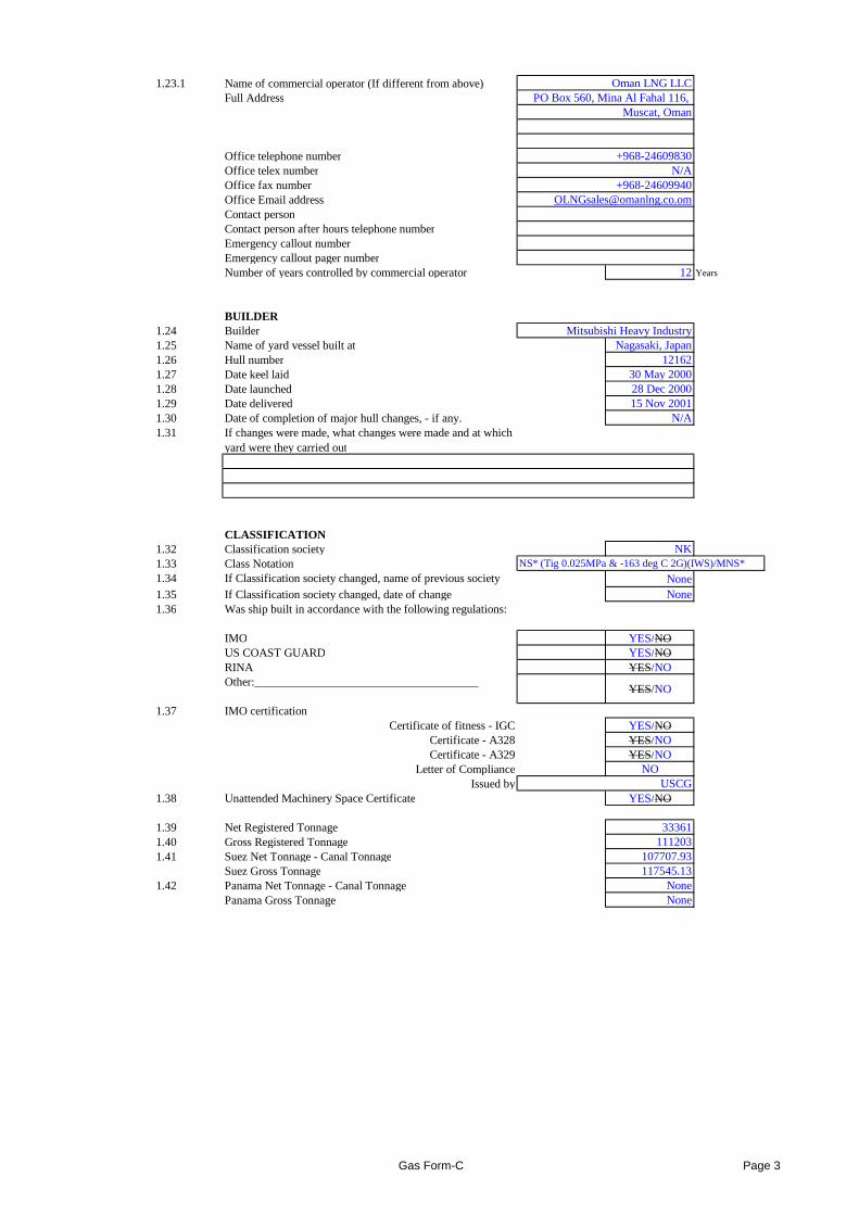
1.23.1 Name of commercial operator (If different from above) Oman LNG LLCFull Address PO Box 560, Mina Al Fahal 116,
Muscat, Oman
Office telephone number +968-24609830Office telex number N/AOffice fax number +968-24609940Office Email address [email protected] personContact person after hours telephone numberEmergency callout numberEmergency callout pager numberNumber of years controlled by commercial operator 12 Years
BUILDER1.24 Builder1.25 Name of yard vessel built at Nagasaki, Japan1.26 Hull number 121621.27 Date keel laid 30 May 20001.28 Date launched 28 Dec 20001.29 Date delivered 15 Nov 20011.30 Date of completion of major hull changes, - if any. N/A1.31 If changes were made, what changes were made and at which
yard were they carried out
CLASSIFICATION1.32 Classification society NK1.33 Class Notation NS* (Tig 0.025MPa & -163 deg C 2G)(IWS)/MNS*
1.34 If Classification society changed, name of previous society None1.35 If Classification society changed, date of change None1.36 Was ship built in accordance with the following regulations:
Mitsubishi Heavy Industry
1.36 Was ship built in accordance with the following regulations:
IMO YES/NOUS COAST GUARD YES/NORINA YES/NOOther:______________________________________
YES/NO
1.37 IMO certificationCertificate of fitness - IGC YES/NO
Certificate - A328 YES/NOCertificate - A329 YES/NO
Letter of Compliance NOIssued by USCG
1.38 Unattended Machinery Space Certificate YES/NO
1.39 Net Registered Tonnage 333611.40 Gross Registered Tonnage 1112031.41 Suez Net Tonnage - Canal Tonnage 107707.93
Suez Gross Tonnage 117545.131.42 Panama Net Tonnage - Canal Tonnage None
Panama Gross Tonnage None
Gas Form-C Page 3
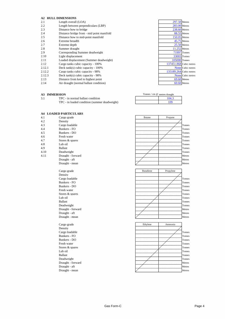
A2 HULL DIMENSIONS2.1 Length overall (LOA) 297.50Metres
2.2 Length between perpendiculars (LBP) 283.00Metres
2.3 Distance bow to bridge 238.60Metres
2.4 Distance bridge front - mid point manifold 88.55Metres
2.5 Distance bow to mid-point manifold 150.05Metres
2.6 Extreme breadth 45.75Metres
2.7 Extreme depth 25.50Metres
2.8 Summer draught 11.252Metres
2.9 Corresponding Summer deadweight 71997Tonnes
2.10 Light displacement 33003Tonnes
2.11 Loaded displacement (Summer deadweight) 105000Tonnes
2.12 Cargo tanks cubic capacity - 100% 137451.868Cubic metres
2.12.1 Deck tank(s) cubic capacity - 100% NoneCubic metres
2.12.2 Cargo tanks cubic capacity - 98% 135189.264Cubic metres
2.12.3 Deck tank(s) cubic capacity - 98% NoneCubic metres
2.13 Distance from keel to highest point 69.60Metres
2.14 Air draught (normal ballast condition) 60.60Metres
A3 IMMERSION Tonnes / cm @metres draught
3.1 TPC - in normal ballast condition 104.3TPC - in loaded condition (summer deadweight) 109
A4 LOADED PARTICULARS4.1 Cargo grade Butane Propane
4.2 Density4.3 Cargo loadable Tonnes
4.4 Bunkers - FO Tonnes
4.5 Bunkers - DO Tonnes
4.6 Fresh water Tonnes
4.7 Stores & spares Tonnes
4.8 Lub oil Tonnes
4.9 Ballast Tonnes
4.10 Deadweight Tonnes
4.11 Draught - forward Metres
Draught - aft MetresDraught - aft Metres
Draught - mean Metres
Cargo grade Butadiene Propylene
DensityCargo loadable Tonnes
Bunkers - FO Tonnes
Bunkers - DO Tonnes
Fresh water Tonnes
Stores & spares Tonnes
Lub oil Tonnes
Ballast Tonnes
Deadweight Tonnes
Draught - forward Metres
Draught - aft Metres
Draught - mean Metres
Cargo grade Ethylene Ammonia
DensityCargo loadable Tonnes
Bunkers - FO Tonnes
Bunkers - DO Tonnes
Fresh water Tonnes
Stores & spares Tonnes
Lub oil Tonnes
Ballast Tonnes
Deadweight Tonnes
Draught - forward Metres
Draught - aft Metres
Draught - mean Metres
Gas Form-C Page 4
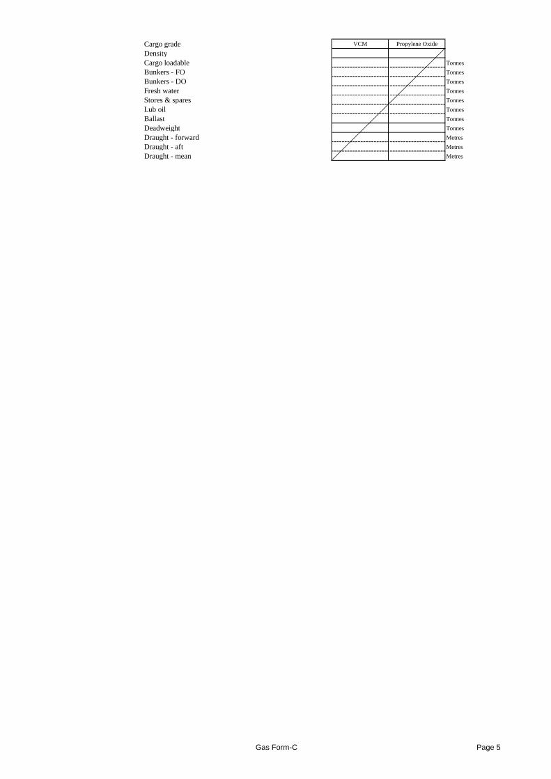
Cargo grade VCM Propylene Oxide
DensityCargo loadable Tonnes
Bunkers - FO Tonnes
Bunkers - DO Tonnes
Fresh water Tonnes
Stores & spares Tonnes
Lub oil Tonnes
Ballast Tonnes
Deadweight Tonnes
Draught - forward Metres
Draught - aft Metres
Draught - mean Metres
Gas Form-C Page 5
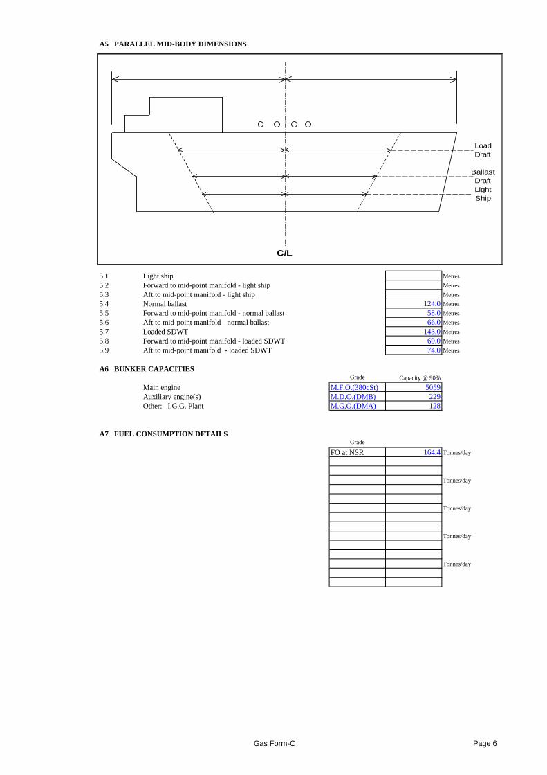
A5 PARALLEL MID-BODY DIMENSIONS
5.1 Light ship Metres
5.2 Forward to mid-point manifold - light ship Metres
5.3 Aft to mid-point manifold - light ship Metres
5.4 Normal ballast 124.0Metres
5.5 Forward to mid-point manifold - normal ballast 58.0 Metres
5.6 Aft to mid-point manifold - normal ballast 66.0 Metres
5.7 Loaded SDWT 143.0Metres
5.8 Forward to mid-point manifold - loaded SDWT 69.0 Metres
5.9 Aft to mid-point manifold - loaded SDWT 74.0 Metres
A6 BUNKER CAPACITIESGrade Capacity @ 90%
Main engine M.F.O.(380cSt) 5059
LoadDraft
BallastDraftLightShip
C/L
Main engine M.F.O.(380cSt) 5059Auxiliary engine(s) M.D.O.(DMB) 229Other: I.G.G. Plant M.G.O.(DMA) 128
A7 FUEL CONSUMPTION DETAILSGrade
FO at NSR 164.4Tonnes/day
Tonnes/day
Tonnes/day
Tonnes/day
Tonnes/day
Gas Form-C Page 6
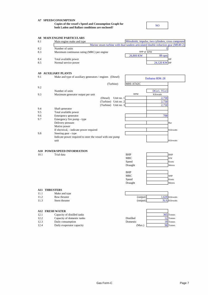
A7 SPEED/CONSUMPTIONCopies of the vessel's Speed and Consumption Graph for both Laden and Ballast conditions are enclosed?
NO
A8 MAIN ENGINE PARTICULARS8.1 Main engine make and type
8.2 Number of units 18.3 Maximum continuous rating (MRC) per engine SHP @RPM
26,800 KW 89 rpm8.4 Total available power HP
8.5 Normal service power 24,120 KWHP
A9 AUXILIARY PLANTS9.1 Make and type of auxiliary generators / engines (Diesel)
(Turbine) MHI-AT42C9.2
Number of units DGx1, TGx39.3 Maximum generator output per unit RPM Kilowatts
(Diesel) Unit no. 1 2,750(Turbine) Unit no. 2 2,750(Turbine) Unit no. 3 2,750
9.4 Shaft generator9.5 Total available power9.6 Emergency generator 7009.7 Emergency fire pump - type
Delivery pressure Bar
Motive powerIf electrical, - indicate power required Kilowatts
9.8 Steering gear - typeIndicate power required to steer the vessel with one pump unit Kilowatts
Mitsubishi, impulse, two cylinders, cross compoundMarine steam turbine with dual tandem articulated double reduction gear (MS40-2)
Daihatsu 8DK-28
A10 POWER/SPEED INFORMATION10.1 Trial data BHP BHP
MRC KW
Speed Knots
Draught Metres
BHPMRC SHP
Speed Knots
Draught Metres
A11 THRUSTERS11.1 Make and type11.2 Bow thruster (output) 1,620Kilowatts
11.3 Stern thruster (output) N/A Kilowatts
A12 FRESH WATER12.1 Capacity of distilled tanks 365 Tonnes
12.2 Capacity of domestic tanks Distilled 12 Tonnes
12.3 Daily consumption Domestic 18 Tonnes
12.4 Daily evaporator capacity (Max.) 90 Tonnes
Gas Form-C Page 7
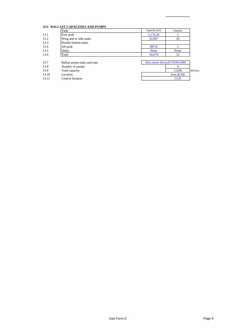
A13 BALLAST CAPACITIES AND PUMPSTank Capacity (m3) Number
13.1 Fore peak 1,174.20 113.2 Wing and or side tanks 52,007 2013.3 Double bottom tanks13.4 Aft peak 897.8 113.5 Other: None None13.6 Total 54,079 22
13.7 Ballast pump make and type13.8 Number of pumps 413.9 Total capacity 11200 M3/hour
13.10 Location Fore & ER13.11 Control location CCR
Elect.motor driven,RVD500-2MH
Gas Form-C Page 8
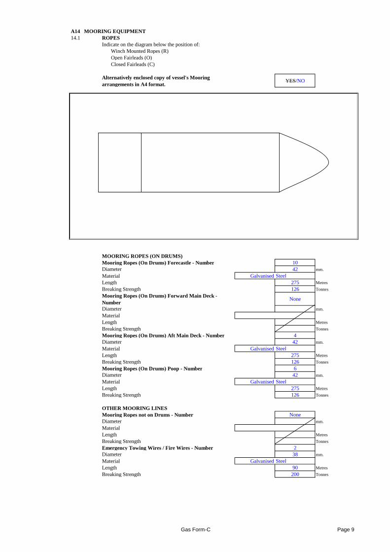
A14 MOORING EQUIPMENT14.1 ROPES
Indicate on the diagram below the position of:Winch Mounted Ropes (R)Open Fairleads (O)Closed Fairleads (C)
Alternatively enclosed copy of vessel's Mooring arrangements in A4 format.
YES/NO
MOORING ROPES (ON DRUMS)Mooring Ropes (On Drums) Forecastle - Number 10Diameter 42 mm.
Material GalvanisedSteelMaterial GalvanisedSteelLength 275 Metres
Breaking Strength 126 Tonnes
Mooring Ropes (On Drums) Forward Main Deck - Number
None
Diameter mm.
MaterialLength Metres
Breaking Strength Tonnes
Mooring Ropes (On Drums) Aft Main Deck - Number 4Diameter 42 mm.
Material GalvanisedSteelLength 275 Metres
Breaking Strength 126 Tonnes
Mooring Ropes (On Drums) Poop - Number 6Diameter 42 mm.
Material GalvanisedSteelLength 275 Metres
Breaking Strength 126 Tonnes
OTHER MOORING LINESMooring Ropes not on Drums - Number NoneDiameter mm.
MaterialLength Metres
Breaking Strength Tonnes
Emergency Towing Wires / Fire Wires - Number 2Diameter 38 mm.
Material GalvanisedSteelLength 90 Metres
Breaking Strength 200 Tonnes
Gas Form-C Page 9
14.2 MOORING WINCHESForecastle - Number 5Single Drum or Double Drums DoubleSplit Drums Y/N YesMotive Power HydraulicHeaving Power 30 Tonnes
Brake Capacity 75 Tonnes
Hauling Speed 15 Metres/Min.
Forward Main Deck - Number NoneSingle Drum or Double DrumsSplit Drums Y/NMotive PowerHeaving Power Tonnes
Brake Capacity Tonnes
Hauling Speed Metres/Min.
Aft Main Deck - Number 2Single Drum or Double Drums DoubleSplit Drums Y/N YesMotive Power HydraulicHeaving Power 30 Tonnes
Brake Capacity 75 Tonnes
Hauling Speed 15 Metres/Min.
Poop - Number 3Single Drum or Double Drums DoubleSplit Drums Y/N YesMotive Power HydraulicHeaving Power 30 Tonnes
Brake Capacity 75 Tonnes
Hauling Speed 15 Metres/Min.
14.3 ANCHORS AND WINDLASSWindlass motive power(e.g. steam, hydraulic) Hydraulic
Hauling power 155 / 63 Tonnes
Brake holding power Tonnes
Anchor typeWeight 21.5 Tonnes
Is spare anchor carried NO
Cast steel, stockless JIS type
Is spare anchor carried NOCable diameter 117 mm.
Number of shackles port cable 14Number of shackles starboard cable 14
14.4 TOWING ARRANGEMENTSIs the vessel fitted with a Towing Bracket Aft? YES
If Yes, state SWL 200 Tonnes
Is Towing chain provided YESDimensions of Towing wire Diameter 85 mm.
Length 80 Metres
14.5 WINDAGEWindage on ballast draught End-on 1633 Squaremetres
Lateral 8091 Squaremetres
Gas Form-C Page 10
A15 NAVIGATIONAL EQUIPMENT15.1 Magnetic compass YES15.2 Off Course Alarm - Magnetic compass YES15.3 Gyro compass YES
Number of Units 215.4 Off Course Alarm - Gyro compass YES15.5 Gyro (Bridge) Repeaters YES
Number of Units 415.6 Radar 3cm YES15.7 Radar 10cm YES15.8 Are radars gyro stabilised? YES15.9 Radar plotting equipment YES15.10 ARPA YES15.11 ECDIS C-MAP15.12 Depth sounder with recorder YES15.13 Depth sounder without recorder YES15.14 Speed/distance indicator YES15.15 Doppler log YES15.16 Docking approach Doppler YES15.17 Rudder angle indicator YES15.18 Rudder angle indicator on Each Bridge Wing YES15.19 RPM indicator YES15.20 RPM indicator on Each Bridge Wing YES15.21 Controllable pitch propeller indicator NONE15.22 Thruster(s) indicator YES15.23 Rate of turn indicator YES15.24 Radio direction finder NO15.25 Navtex receiver YES15.26 GPS YES15.26.1 DGPS YES15.27 Transit SATNAV NO15.28 Decca navigator NO15.29 Omega NO15.30 Loran C NO15.31 Weather fax YES15.32 Sextant(s) YES15.33 Signal lamp ALDIS YES15.34 Anemometer YES15.34 Anemometer YES15.35 Engine order recorder YES15.35.1 VDR (Voyage Data Recorder) YES15.36 Course recorder YES15.37 Are steering motor controls and engine controls fitted on
bridge wings?NO
15.38 Is bridge equipped with a 'Dead-Man' alarm? YES15.39 What chart outfit coverage is provided World-wide NO
Limited YESIf limited, - please indicate area(s) covered
15.40 Formal chart correction system in use YES15.41 Electronic Chart system in use NO
JP, Far E, NW Aus, W Eur, N Am
Gas Form-C Page 11
A16 COMMUNICATIONS AND ELECTRONICS16.2 What GMDSS areas is the vessel classed for? A1 A2 A3 A4
A1,A2 & A3
16.3 Transponder (SART) YES16.4 EPIRB YES16.5 How many VHF radios are fitted on the bridge? 216.6 Is vessel fitted with VHF in the cargo control room (CCR)?
YES
16.7 Is the CCR connected to the vessel's internal communication system?
YES
16.8 How many intrinsically safe walkie talkies are provided for cargo handling?
12
16.9 Is vessel fitted with an INMARSAT satellite communications system?
YES
16.10 Does vessel carry at least three survival craft two-way radio telephones?
YES
16.11 Inmarsat satellite system YESSpecify system type A, B or C B and C & V-SAT
16.12 2182kHz bridge auto alarm YES16.13 Radio telephone distress frequency watch receiver YES16.14 Emergency lifeboat transceiver YES16.15 Can vessel transmit the helicopter homing signal on 410 kHz?
YES
16.16 Full set of Radio List publications YES
Gas Form-C Page 12
SECTION BCARGO SYSTEMS
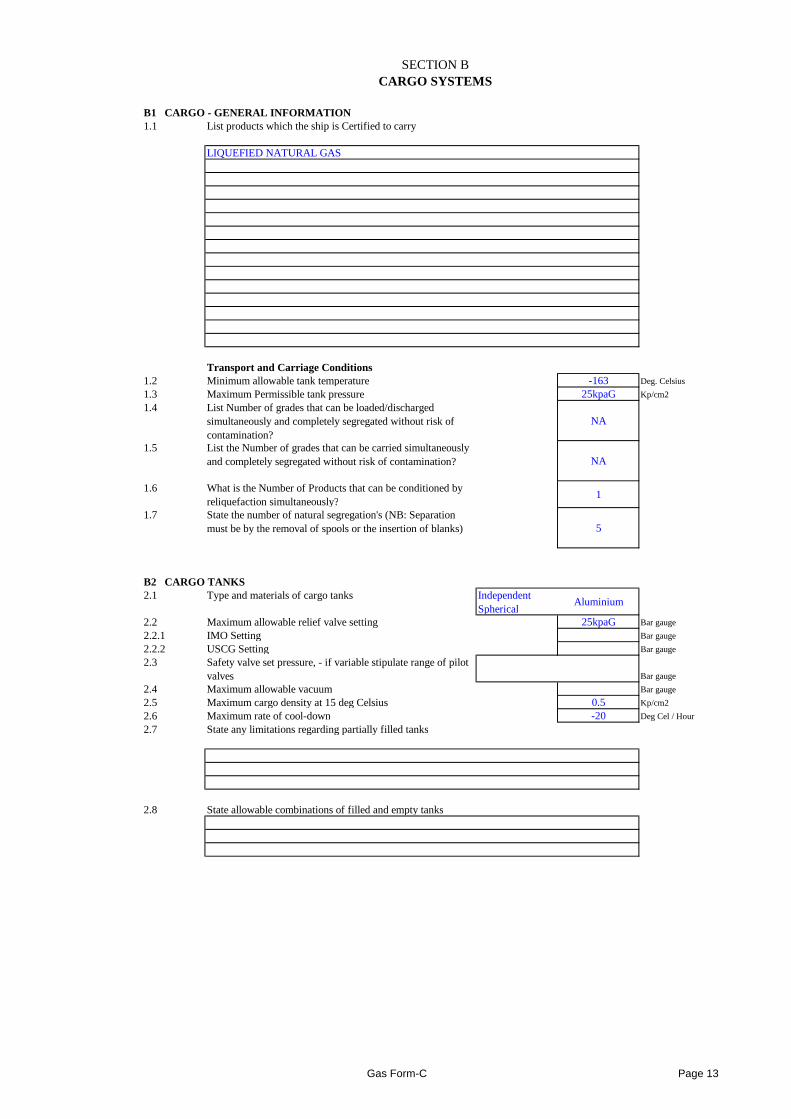
B1 CARGO - GENERAL INFORMATION1.1 List products which the ship is Certified to carry
LIQUEFIED NATURAL GAS
Transport and Carriage Conditions1.2 Minimum allowable tank temperature -163 Deg. Celsius
1.3 Maximum Permissible tank pressure 25kpaG Kp/cm2
1.4 List Number of grades that can be loaded/discharged simultaneously and completely segregated without risk of contamination?
NA
1.5 List the Number of grades that can be carried simultaneously and completely segregated without risk of contamination? NA
1.6 What is the Number of Products that can be conditioned by reliquefaction simultaneously?
1
1.7 State the number of natural segregation's (NB: Separation must be by the removal of spools or the insertion of blanks) 5
B2 CARGO TANKS2.1 Type and materials of cargo tanks Independent
SphericalAluminium
2.2 Maximum allowable relief valve setting 25kpaG Bar gauge
2.2.1 IMO Setting Bar gauge
2.2.2 USCG Setting Bar gauge
2.3 Safety valve set pressure, - if variable stipulate range of pilot valves Bar gauge
2.4 Maximum allowable vacuum Bar gauge
2.5 Maximum cargo density at 15 deg Celsius 0.5 Kp/cm2
2.6 Maximum rate of cool-down -20 Deg Cel / Hour
2.7 State any limitations regarding partially filled tanks
2.8 State allowable combinations of filled and empty tanks
Gas Form-C Page 13
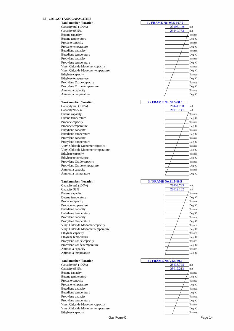
B3 CARGO TANK CAPACITIESTank number / location 1 / FRAME No. 99.5-107.5Capacity m3 (100%) 23493.149 m3
Capacity 98.5% 23140.752 m3
Butane capacity Tonnes
Butane temperature Deg. C
Propane capacity Tonnes
Propane temperature Deg. C
Butadiene capacity Tonnes
Butadiene temperature Deg. C
Propylene capacity Tonnes
Propylene temperature Deg. C
Vinyl Chloride Monomer capacity Tonnes
Vinyl Chloride Monomer temperature Deg. C
Ethylene capacity Tonnes
Ethylene temperature Deg. C
Propylene Oxide capacity Tonnes
Propylene Oxide temperature Deg. C
Ammonia capacity Tonnes
Ammonia temperature Deg. C
Tank number / location 2 / FRAME No. 90.5-98.5Capacity m3 (100%) 28441.768 m3
Capacity 98.5% 28015.141 m3
Butane capacity Tonnes
Butane temperature Deg. C
Propane capacity Tonnes
Propane temperature Deg. C
Butadiene capacity Tonnes
Butadiene temperature Deg. C
Propylene capacity Tonnes
Propylene temperature Deg. C
Vinyl Chloride Monomer capacity Tonnes
Vinyl Chloride Monomer temperature Deg. C
Ethylene capacity Tonnes
Ethylene temperature Deg. C
Propylene Oxide capacity Tonnes
Propylene Oxide temperature Deg. CPropylene Oxide temperature Deg. C
Ammonia capacity Tonnes
Ammonia temperature Deg. C
Tank number / location 3 / FRAME No.81.5-89.5Capacity m3 (100%) 28438.743 m3
Capacity 98% 28012.162 m3
Butane capacity Tonnes
Butane temperature Deg. C
Propane capacity Tonnes
Propane temperature Deg. C
Butadiene capacity Tonnes
Butadiene temperature Deg. C
Propylene capacity Tonnes
Propylene temperature Deg. C
Vinyl Chloride Monomer capacity Tonnes
Vinyl Chloride Monomer temperature Deg. C
Ethylene capacity Tonnes
Ethylene temperature Deg. C
Propylene Oxide capacity Tonnes
Propylene Oxide temperature Deg. C
Ammonia capacity Tonnes
Ammonia temperature Deg. C
Tank number / location 4 / FRAME No. 72.5-80.5Capacity m3 (100%) 28438.795 m3
Capacity 98.5% 28012.213 m3
Butane capacity Tonnes
Butane temperature Deg. C
Propane capacity Tonnes
Propane temperature Deg. C
Butadiene capacity Tonnes
Butadiene temperature Deg. C
Propylene capacity Tonnes
Propylene temperature Deg. C
Vinyl Chloride Monomer capacity Tonnes
Vinyl Chloride Monomer temperature Deg. C
Ethylene capacity Tonnes
Gas Form-C Page 14
Ethylene temperature Deg. C
Propylene Oxide capacity Tonnes
Propylene Oxide temperature Deg. C
Ammonia capacity Tonnes
Ammonia temperature Deg. C
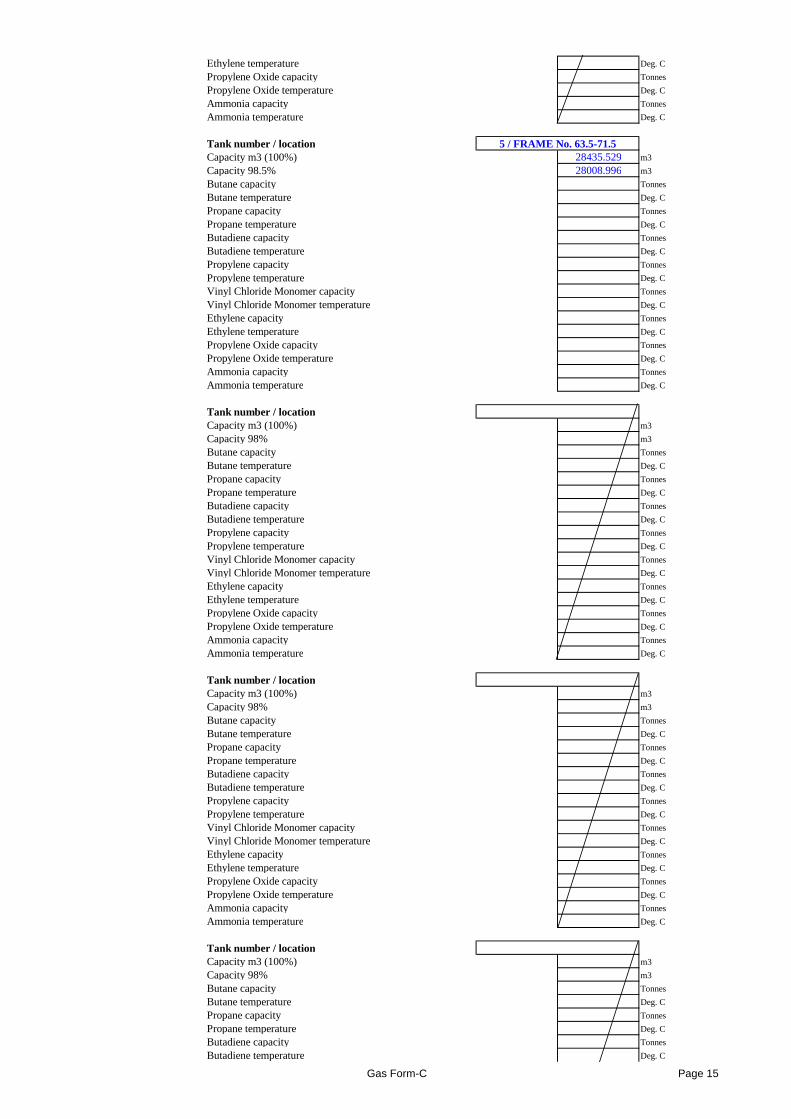
Tank number / location 5 / FRAME No. 63.5-71.5Capacity m3 (100%) 28435.529 m3
Capacity 98.5% 28008.996 m3
Butane capacity Tonnes
Butane temperature Deg. C
Propane capacity Tonnes
Propane temperature Deg. C
Butadiene capacity Tonnes
Butadiene temperature Deg. C
Propylene capacity Tonnes
Propylene temperature Deg. C
Vinyl Chloride Monomer capacity Tonnes
Vinyl Chloride Monomer temperature Deg. C
Ethylene capacity Tonnes
Ethylene temperature Deg. C
Propylene Oxide capacity Tonnes
Propylene Oxide temperature Deg. C
Ammonia capacity Tonnes
Ammonia temperature Deg. C
Tank number / locationCapacity m3 (100%) m3
Capacity 98% m3
Butane capacity Tonnes
Butane temperature Deg. C
Propane capacity Tonnes
Propane temperature Deg. C
Butadiene capacity Tonnes
Butadiene temperature Deg. C
Propylene capacity Tonnes
Propylene temperature Deg. C
Vinyl Chloride Monomer capacity TonnesVinyl Chloride Monomer capacity Tonnes
Vinyl Chloride Monomer temperature Deg. C
Ethylene capacity Tonnes
Ethylene temperature Deg. C
Propylene Oxide capacity Tonnes
Propylene Oxide temperature Deg. C
Ammonia capacity Tonnes
Ammonia temperature Deg. C
Tank number / locationCapacity m3 (100%) m3
Capacity 98% m3
Butane capacity Tonnes
Butane temperature Deg. C
Propane capacity Tonnes
Propane temperature Deg. C
Butadiene capacity Tonnes
Butadiene temperature Deg. C
Propylene capacity Tonnes
Propylene temperature Deg. C
Vinyl Chloride Monomer capacity Tonnes
Vinyl Chloride Monomer temperature Deg. C
Ethylene capacity Tonnes
Ethylene temperature Deg. C
Propylene Oxide capacity Tonnes
Propylene Oxide temperature Deg. C
Ammonia capacity Tonnes
Ammonia temperature Deg. C
Tank number / locationCapacity m3 (100%) m3
Capacity 98% m3
Butane capacity Tonnes
Butane temperature Deg. C
Propane capacity Tonnes
Propane temperature Deg. C
Butadiene capacity Tonnes
Butadiene temperature Deg. C
Gas Form-C Page 15
Propylene capacity Tonnes
Propylene temperature Deg. C
Vinyl Chloride Monomer capacity Tonnes
Vinyl Chloride Monomer temperature Deg. C
Ethylene capacity Tonnes
Ethylene temperature Deg. C
Propylene Oxide capacity Tonnes
Propylene Oxide temperature Deg. C
Ammonia capacity Tonnes
Ammonia temperature Deg. C
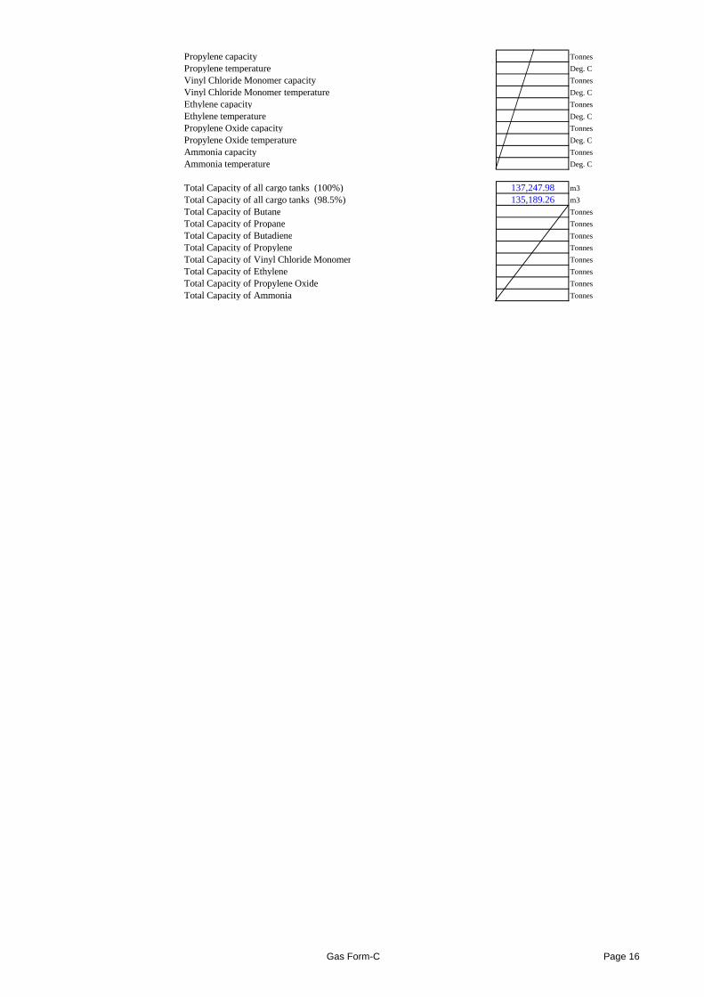
Total Capacity of all cargo tanks (100%) 137,247.98 m3
Total Capacity of all cargo tanks (98.5%) 135,189.26 m3
Total Capacity of Butane Tonnes
Total Capacity of Propane Tonnes
Total Capacity of Butadiene Tonnes
Total Capacity of Propylene Tonnes
Total Capacity of Vinyl Chloride Monomer Tonnes
Total Capacity of Ethylene Tonnes
Total Capacity of Propylene Oxide Tonnes
Total Capacity of Ammonia Tonnes
Gas Form-C Page 16
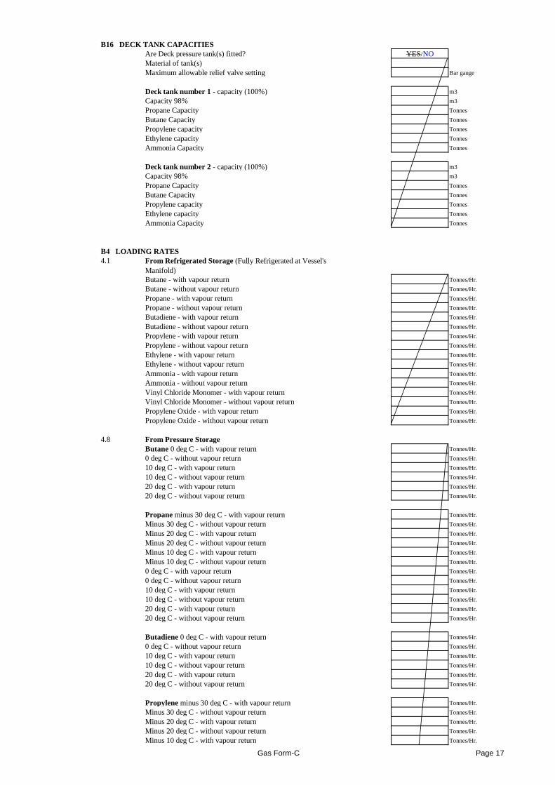
B16 DECK TANK CAPACITIESAre Deck pressure tank(s) fitted? YES/NOMaterial of tank(s)Maximum allowable relief valve setting Bar gauge
Deck tank number 1 - capacity (100%) m3
Capacity 98% m3
Propane Capacity Tonnes
Butane Capacity Tonnes
Propylene capacity Tonnes
Ethylene capacity Tonnes
Ammonia Capacity Tonnes
Deck tank number 2 - capacity (100%) m3
Capacity 98% m3
Propane Capacity Tonnes
Butane Capacity Tonnes
Propylene capacity Tonnes
Ethylene capacity Tonnes
Ammonia Capacity Tonnes
B4 LOADING RATES4.1 From Refrigerated Storage (Fully Refrigerated at Vessel's
Manifold)Butane - with vapour return Tonnes/Hr.
Butane - without vapour return Tonnes/Hr.
Propane - with vapour return Tonnes/Hr.
Propane - without vapour return Tonnes/Hr.
Butadiene - with vapour return Tonnes/Hr.
Butadiene - without vapour return Tonnes/Hr.
Propylene - with vapour return Tonnes/Hr.
Propylene - without vapour return Tonnes/Hr.
Ethylene - with vapour return Tonnes/Hr.
Ethylene - without vapour return Tonnes/Hr.
Ammonia - with vapour return Tonnes/Hr.
Ammonia - without vapour return Tonnes/Hr.
Vinyl Chloride Monomer - with vapour return Tonnes/Hr.Vinyl Chloride Monomer - with vapour return Tonnes/Hr.
Vinyl Chloride Monomer - without vapour return Tonnes/Hr.
Propylene Oxide - with vapour return Tonnes/Hr.
Propylene Oxide - without vapour return Tonnes/Hr.
4.8 From Pressure StorageButane 0 deg C - with vapour return Tonnes/Hr.
0 deg C - without vapour return Tonnes/Hr.
10 deg C - with vapour return Tonnes/Hr.
10 deg C - without vapour return Tonnes/Hr.
20 deg C - with vapour return Tonnes/Hr.
20 deg C - without vapour return Tonnes/Hr.
Propane minus 30 deg C - with vapour return Tonnes/Hr.
Minus 30 deg C - without vapour return Tonnes/Hr.
Minus 20 deg C - with vapour return Tonnes/Hr.
Minus 20 deg C - without vapour return Tonnes/Hr.
Minus 10 deg C - with vapour return Tonnes/Hr.
Minus 10 deg C - without vapour return Tonnes/Hr.
0 deg C - with vapour return Tonnes/Hr.
0 deg C - without vapour return Tonnes/Hr.
10 deg C - with vapour return Tonnes/Hr.
10 deg C - without vapour return Tonnes/Hr.
20 deg C - with vapour return Tonnes/Hr.
20 deg C - without vapour return Tonnes/Hr.
Butadiene 0 deg C - with vapour return Tonnes/Hr.
0 deg C - without vapour return Tonnes/Hr.
10 deg C - with vapour return Tonnes/Hr.
10 deg C - without vapour return Tonnes/Hr.
20 deg C - with vapour return Tonnes/Hr.
20 deg C - without vapour return Tonnes/Hr.
Propylene minus 30 deg C - with vapour return Tonnes/Hr.
Minus 30 deg C - without vapour return Tonnes/Hr.
Minus 20 deg C - with vapour return Tonnes/Hr.
Minus 20 deg C - without vapour return Tonnes/Hr.
Minus 10 deg C - with vapour return Tonnes/Hr.
Gas Form-C Page 17
Minus 10 deg C - without vapour return Tonnes/Hr.
0 deg C - with vapour return Tonnes/Hr.
0 deg C - without vapour return Tonnes/Hr.
10 deg C - with vapour return Tonnes/Hr.
10 deg C - without vapour return Tonnes/Hr.
20 deg C - with vapour return Tonnes/Hr.
20 deg C - without vapour return Tonnes/Hr.
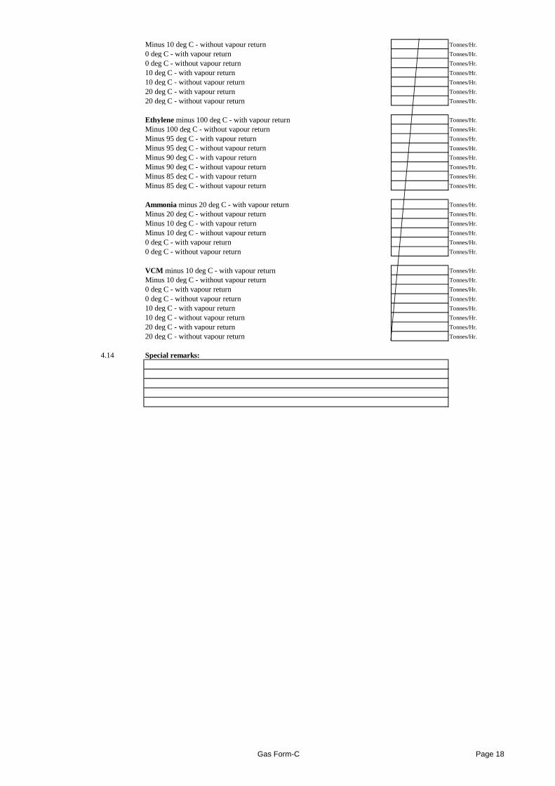
Ethylene minus 100 deg C - with vapour return Tonnes/Hr.
Minus 100 deg C - without vapour return Tonnes/Hr.
Minus 95 deg C - with vapour return Tonnes/Hr.
Minus 95 deg C - without vapour return Tonnes/Hr.
Minus 90 deg C - with vapour return Tonnes/Hr.
Minus 90 deg C - without vapour return Tonnes/Hr.
Minus 85 deg C - with vapour return Tonnes/Hr.
Minus 85 deg C - without vapour return Tonnes/Hr.
Ammonia minus 20 deg C - with vapour return Tonnes/Hr.
Minus 20 deg C - without vapour return Tonnes/Hr.
Minus 10 deg C - with vapour return Tonnes/Hr.
Minus 10 deg C - without vapour return Tonnes/Hr.
0 deg C - with vapour return Tonnes/Hr.
0 deg C - without vapour return Tonnes/Hr.
VCM minus 10 deg C - with vapour return Tonnes/Hr.
Minus 10 deg C - without vapour return Tonnes/Hr.
0 deg C - with vapour return Tonnes/Hr.
0 deg C - without vapour return Tonnes/Hr.
10 deg C - with vapour return Tonnes/Hr.
10 deg C - without vapour return Tonnes/Hr.
20 deg C - with vapour return Tonnes/Hr.
20 deg C - without vapour return Tonnes/Hr.
4.14 Special remarks:
Gas Form-C Page 18
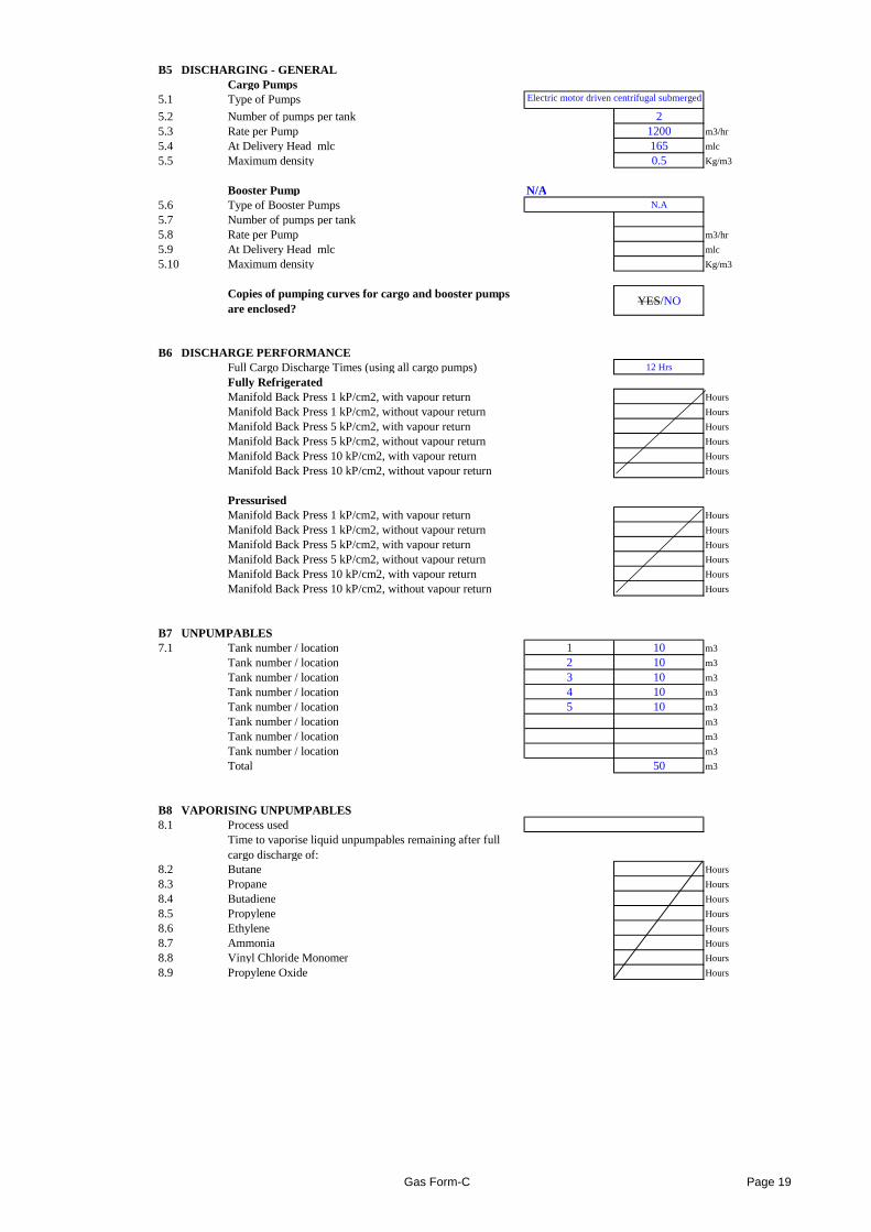
B5 DISCHARGING - GENERALCargo Pumps
5.1 Type of Pumps
5.2 Number of pumps per tank 25.3 Rate per Pump 1200 m3/hr
5.4 At Delivery Head mlc 165 mlc
5.5 Maximum density 0.5 Kg/m3
Booster Pump N/A5.6 Type of Booster Pumps N.A
5.7 Number of pumps per tank5.8 Rate per Pump m3/hr
5.9 At Delivery Head mlc mlc
5.10 Maximum density Kg/m3
Copies of pumping curves for cargo and booster pumps are enclosed?
YES/NO
B6 DISCHARGE PERFORMANCEFull Cargo Discharge Times (using all cargo pumps) 12 Hrs
Fully RefrigeratedManifold Back Press 1 kP/cm2, with vapour return Hours
Manifold Back Press 1 kP/cm2, without vapour return Hours
Manifold Back Press 5 kP/cm2, with vapour return Hours
Manifold Back Press 5 kP/cm2, without vapour return Hours
Manifold Back Press 10 kP/cm2, with vapour return Hours
Manifold Back Press 10 kP/cm2, without vapour return Hours
PressurisedManifold Back Press 1 kP/cm2, with vapour return Hours
Manifold Back Press 1 kP/cm2, without vapour return Hours
Manifold Back Press 5 kP/cm2, with vapour return Hours
Manifold Back Press 5 kP/cm2, without vapour return Hours
Manifold Back Press 10 kP/cm2, with vapour return Hours
Manifold Back Press 10 kP/cm2, without vapour return Hours
Electric motor driven centrifugal submerged
B7 UNPUMPABLES7.1 Tank number / location 1 10 m3
Tank number / location 2 10 m3
Tank number / location 3 10 m3
Tank number / location 4 10 m3
Tank number / location 5 10 m3
Tank number / location m3
Tank number / location m3
Tank number / location m3
Total 50 m3
B8 VAPORISING UNPUMPABLES8.1 Process used
Time to vaporise liquid unpumpables remaining after full cargo discharge of:
8.2 Butane Hours
8.3 Propane Hours
8.4 Butadiene Hours
8.5 Propylene Hours
8.6 Ethylene Hours
8.7 Ammonia Hours
8.8 Vinyl Chloride Monomer Hours
8.9 Propylene Oxide Hours
Gas Form-C Page 19
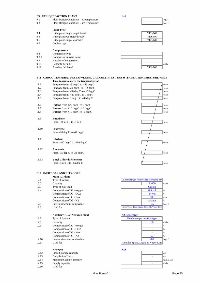
B9 RELIQUEFACTION PLANT N/A9.1 Plant Design Conditions - air temperature Deg. C
9.3 Plant Design Conditions - sea temperature Deg. C
Plant Type9.4 Is the plant single stage/direct? YES/NO9.5 Is the plant two stage/direct? YES/NO9.6 Is the plant simple cascade? YES/NO9.7 Coolant type
Compressors9.8 Compressor type9.8.1 Compressor makers name9.9 Number of compressors9.10 Capacity per unit m3/hr
9.11 Are they Oil Free? YES/NO
B11 CARGO TEMPERATURE LOWERING CAPABILITY (AT SE A WITH SEA TEMPERATURE +15C)Time taken to lower the temperature of:
11.1 Propane from -5 deg C to - 42 deg C Hours
11.2 Propane from -20 deg C to - 42 deg C Hours
11.3 Propane from -38 deg C to - 42deg C Hours
11.4 Propane from +20 deg C to 0 deg C Hours
11.5 Propane from 0 deg C to -20 deg C Hours
11.6 Butane from +20 deg C to 0 deg C Hours
11.7 Butane from +10 deg C to 0 deg C Hours
11.8 Butane from +10 deg C to -5 deg C Hours
11.9 ButadieneFrom +20 deg C to -5 deg C Hours
11.10 PropyleneFrom -20 deg C to -47 deg C Hours
11.11 EthyleneFrom -100 deg C to -104 deg C HoursFrom -100 deg C to -104 deg C Hours
11.12 AmmoniaFrom -15 deg C to -33 deg C Hours
11.13 Vinyl Chloride MonomerFrom -5 deg C to -14 deg C Hours
B12 INERT GAS AND NITROGENMain IG Plant
12.1 Type of system12.2 Capacity 11000 m3/hr
12.3 Type of fuel used Gas oil12.4 Composition of IG - oxygen 0.5 vol %
Composition of IG - CO2 14 vol %
Composition of IG - Nox 100 ppm
Composition of IG - N2 balance %
12.5 Lowest dewpoint achievable -45 Deg. C
12.6 Used for
Auxiliary IG or Nitrogen plant N2 Generator12.7 Type of System
12.8 Capacity 60 m3/hr
12.9 Composition of IG - oxygen - %
Composition of IG - CO2 - %
Composition of IG - Nox - %
Composition of IG - N2 97 %
12.10 Lowest dewpoint achievable -65 Deg. C
12.11 Used for
Nitrogen N/A12.12 Liquid storage capacity - m3
12.13 Daily boil-off loss - m3
12.14 Maximum supply pressure - Kp/Cu. Cm
12.15 Supply capacity - m3/hr
12.16 Used for -
Annuller Space, Liquid & Vapor Line
Oil burning type with cooling and drying unit
Cargo Tank, Hold Space, Liquid & Vapor Line
Membrane permeation type
Gas Form-C Page 20
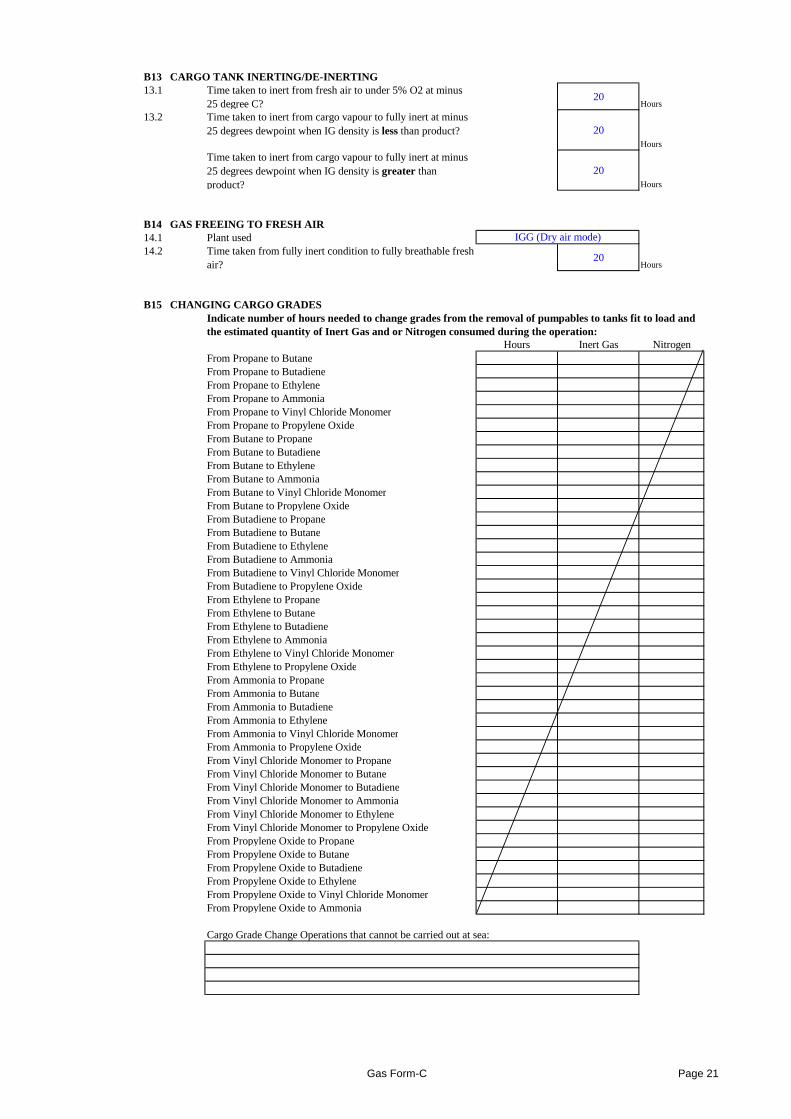
B13 CARGO TANK INERTING/DE-INERTING13.1 Time taken to inert from fresh air to under 5% O2 at minus
25 degree C?20
Hours
13.2 Time taken to inert from cargo vapour to fully inert at minus 25 degrees dewpoint when IG density is less than product? 20
Hours
Time taken to inert from cargo vapour to fully inert at minus 25 degrees dewpoint when IG density is greater than product?
20Hours
B14 GAS FREEING TO FRESH AIR14.1 Plant used14.2 Time taken from fully inert condition to fully breathable fresh
air?20
Hours
B15 CHANGING CARGO GRADESIndicate number of hours needed to change grades from the removal of pumpables to tanks fit to load andthe estimated quantity of Inert Gas and or Nitrogen consumed during the operation:
Hours Inert Gas NitrogenFrom Propane to ButaneFrom Propane to ButadieneFrom Propane to EthyleneFrom Propane to AmmoniaFrom Propane to Vinyl Chloride MonomerFrom Propane to Propylene OxideFrom Butane to PropaneFrom Butane to ButadieneFrom Butane to EthyleneFrom Butane to AmmoniaFrom Butane to Vinyl Chloride MonomerFrom Butane to Propylene OxideFrom Butadiene to PropaneFrom Butadiene to ButaneFrom Butadiene to EthyleneFrom Butadiene to Ammonia
IGG (Dry air mode)
From Butadiene to AmmoniaFrom Butadiene to Vinyl Chloride MonomerFrom Butadiene to Propylene OxideFrom Ethylene to PropaneFrom Ethylene to ButaneFrom Ethylene to ButadieneFrom Ethylene to AmmoniaFrom Ethylene to Vinyl Chloride MonomerFrom Ethylene to Propylene OxideFrom Ammonia to PropaneFrom Ammonia to ButaneFrom Ammonia to ButadieneFrom Ammonia to EthyleneFrom Ammonia to Vinyl Chloride MonomerFrom Ammonia to Propylene OxideFrom Vinyl Chloride Monomer to PropaneFrom Vinyl Chloride Monomer to ButaneFrom Vinyl Chloride Monomer to ButadieneFrom Vinyl Chloride Monomer to AmmoniaFrom Vinyl Chloride Monomer to EthyleneFrom Vinyl Chloride Monomer to Propylene OxideFrom Propylene Oxide to PropaneFrom Propylene Oxide to ButaneFrom Propylene Oxide to ButadieneFrom Propylene Oxide to EthyleneFrom Propylene Oxide to Vinyl Chloride MonomerFrom Propylene Oxide to Ammonia
Cargo Grade Change Operations that cannot be carried out at sea:
Gas Form-C Page 21
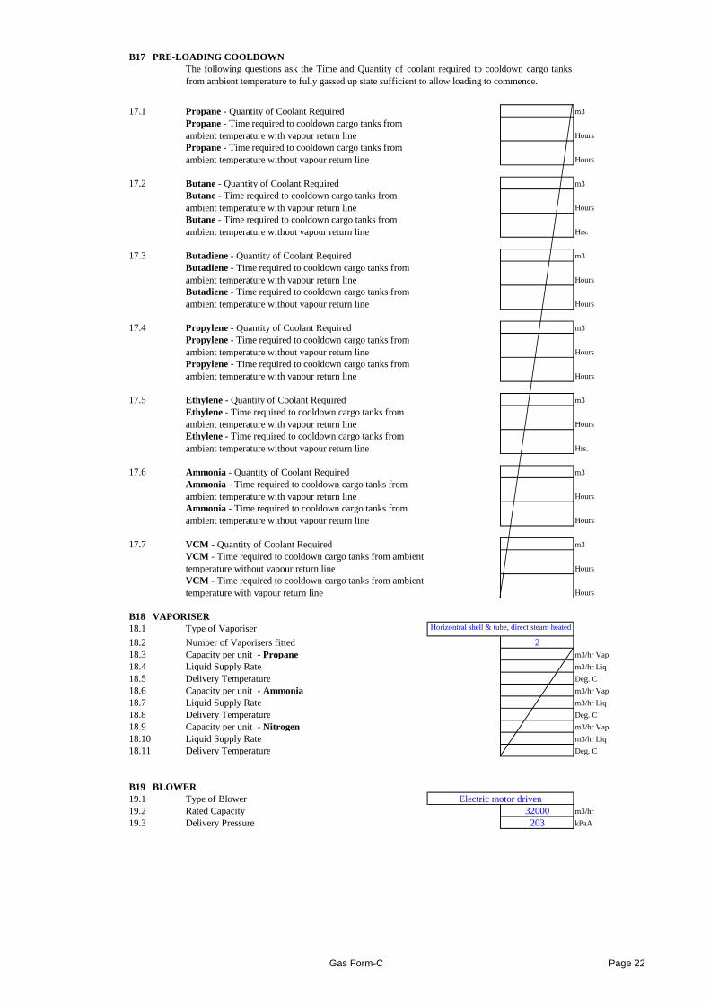
B17 PRE-LOADING COOLDOWN
17.1 Propane - Quantity of Coolant Required m3
Propane - Time required to cooldown cargo tanks from ambient temperature with vapour return line Hours
Propane - Time required to cooldown cargo tanks from ambient temperature without vapour return line Hours
17.2 Butane - Quantity of Coolant Required m3
Butane - Time required to cooldown cargo tanks from ambient temperature with vapour return line Hours
Butane - Time required to cooldown cargo tanks from ambient temperature without vapour return line Hrs.
17.3 Butadiene - Quantity of Coolant Required m3
Butadiene - Time required to cooldown cargo tanks from ambient temperature with vapour return line Hours
Butadiene - Time required to cooldown cargo tanks from ambient temperature without vapour return line Hours
17.4 Propylene - Quantity of Coolant Required m3
Propylene - Time required to cooldown cargo tanks from ambient temperature without vapour return line Hours
Propylene - Time required to cooldown cargo tanks from ambient temperature with vapour return line Hours
17.5 Ethylene - Quantity of Coolant Required m3
Ethylene - Time required to cooldown cargo tanks from ambient temperature with vapour return line Hours
Ethylene - Time required to cooldown cargo tanks from ambient temperature without vapour return line Hrs.
17.6 Ammonia - Quantity of Coolant Required m3
Ammonia - Time required to cooldown cargo tanks from ambient temperature with vapour return line Hours
Ammonia - Time required to cooldown cargo tanks from
The following questions ask the Time and Quantity of coolantrequired to cooldown cargo tanksfrom ambient temperature to fully gassed up state sufficient to allow loading to commence.
Ammonia - Time required to cooldown cargo tanks from ambient temperature without vapour return line Hours
17.7 VCM - Quantity of Coolant Required m3
VCM - Time required to cooldown cargo tanks from ambient temperature without vapour return line Hours
VCM - Time required to cooldown cargo tanks from ambient temperature with vapour return line Hours
B18 VAPORISER18.1 Type of Vaporiser
18.2 Number of Vaporisers fitted 218.3 Capacity per unit - Propane m3/hr Vap
18.4 Liquid Supply Rate m3/hr Liq
18.5 Delivery Temperature Deg. C
18.6 Capacity per unit - Ammonia m3/hr Vap
18.7 Liquid Supply Rate m3/hr Liq
18.8 Delivery Temperature Deg. C
18.9 Capacity per unit - Nitrogen m3/hr Vap
18.10 Liquid Supply Rate m3/hr Liq
18.11 Delivery Temperature Deg. C
B19 BLOWER19.1 Type of Blower19.2 Rated Capacity 32000 m3/hr
19.3 Delivery Pressure 203 kPaA
Electric motor driven
Horizontral shell & tube, direct steam heated
Gas Form-C Page 22
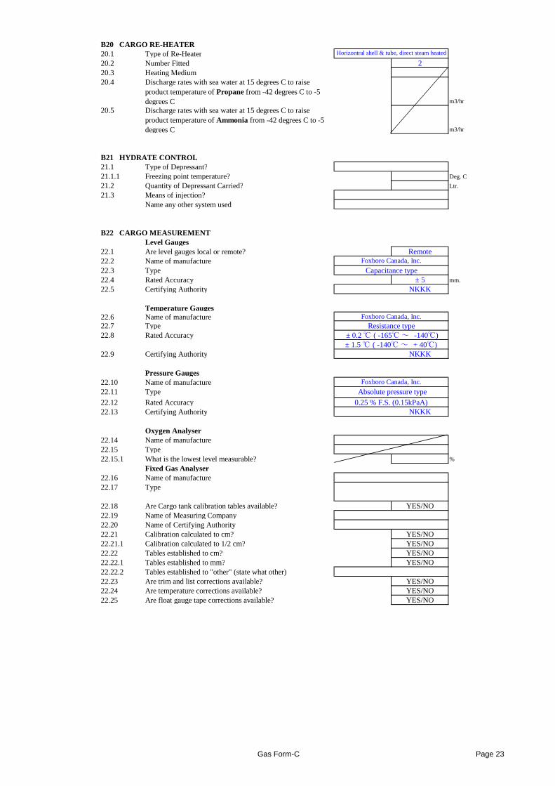
B20 CARGO RE-HEATER20.1 Type of Re-Heater20.2 Number Fitted 220.3 Heating Medium20.4 Discharge rates with sea water at 15 degrees C to raise
product temperature of Propane from -42 degrees C to -5 degrees C m3/hr
20.5 Discharge rates with sea water at 15 degrees C to raise product temperature of Ammonia from -42 degrees C to -5 degrees C m3/hr
B21 HYDRATE CONTROL21.1 Type of Depressant?21.1.1 Freezing point temperature? Deg. C
21.2 Quantity of Depressant Carried? Ltr.
21.3 Means of injection?Name any other system used
B22 CARGO MEASUREMENTLevel Gauges
22.1 Are level gauges local or remote? Remote22.2 Name of manufacture22.3 Type 22.4 Rated Accuracy ± 5 mm.
22.5 Certifying Authority NKKK
Temperature Gauges22.6 Name of manufacture22.7 Type 22.8 Rated Accuracy
22.9 Certifying Authority NKKK
Pressure Gauges22.10 Name of manufacture22.11 Type
Capacitance typeFoxboro Canada, Inc.
Resistance type
Foxboro Canada, Inc.
Absolute pressure type
± 0.2 ℃ ( -165℃ ~ -140℃)± 1.5 ℃ ( -140℃ ~ + 40℃)
Foxboro Canada, Inc.
Horizontral shell & tube, direct steam heated
22.11 Type
22.12 Rated Accuracy
22.13 Certifying Authority NKKK
Oxygen Analyser22.14 Name of manufacture22.15 Type 22.15.1 What is the lowest level measurable? %
Fixed Gas Analyser22.16 Name of manufacture22.17 Type
22.18 Are Cargo tank calibration tables available? YES/NO22.19 Name of Measuring Company22.20 Name of Certifying Authority22.21 Calibration calculated to cm? YES/NO22.21.1 Calibration calculated to 1/2 cm? YES/NO22.22 Tables established to cm? YES/NO22.22.1 Tables established to mm? YES/NO22.22.2 Tables established to "other" (state what other)22.23 Are trim and list corrections available? YES/NO22.24 Are temperature corrections available? YES/NO22.25 Are float gauge tape corrections available? YES/NO
Absolute pressure type
0.25 % F.S. (0.15kPaA)
Gas Form-C Page 23
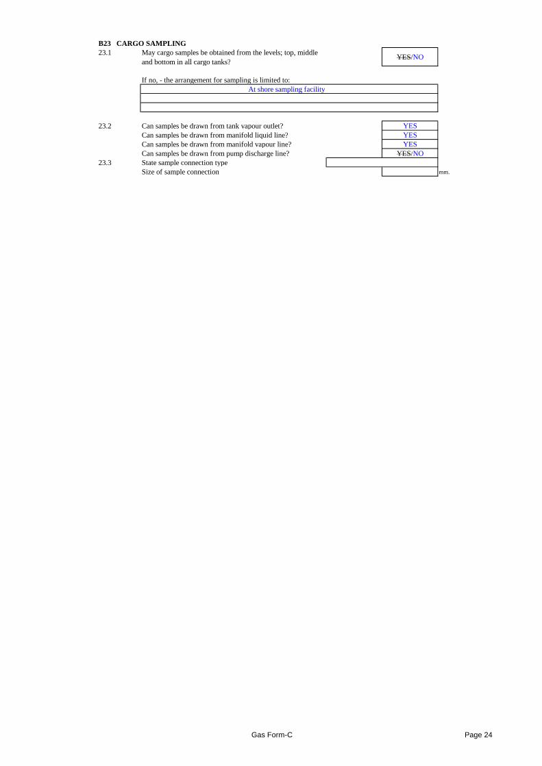
B23 CARGO SAMPLING23.1 May cargo samples be obtained from the levels; top, middle
and bottom in all cargo tanks?YES/NO
If no, - the arrangement for sampling is limited to:At shore sampling facility
23.2 Can samples be drawn from tank vapour outlet? YESCan samples be drawn from manifold liquid line? YESCan samples be drawn from manifold vapour line? YESCan samples be drawn from pump discharge line? YES/NO
23.3 State sample connection type Size of sample connection mm.
Gas Form-C Page 24
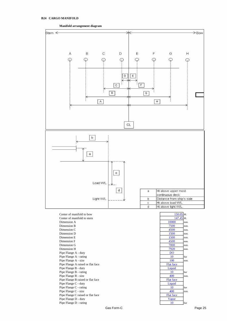
B24 CARGO MANIFOLD
Manifold arrangement diagram
Center of manifold to bow 150.05M.
Center of manifold to stern 147.45M.
Dimension A 10000 mm.
Dimension B 7500 mm.
4500 mm.
Dimension D 1500 mm.
Dimension E 1500 mm.
Dimension F 4500 mm.
Dimension G 7000 mm.
Dimension H 7920 mm.
Pipe Flange A - duty DOPipe Flange A - rating 10 bar
Pipe Flange A - size 100 mm.
Pipe Flange A raised or flat face Flat facePipe Flange B - duty LiquidPipe Flange B - rating 10 bar
Pipe Flange B - size 400 mm.
Pipe Flange B raised or flat face Flat facePipe Flange C - duty LiquidPipe Flange C - rating 10 bar
Pipe Flange C - size 400 mm.
Pipe Flange C raised or flat face Flat facePipe Flange D - duty VaporPipe Flange D - rating 10 bar
Dimension C
Gas Form-C Page 25
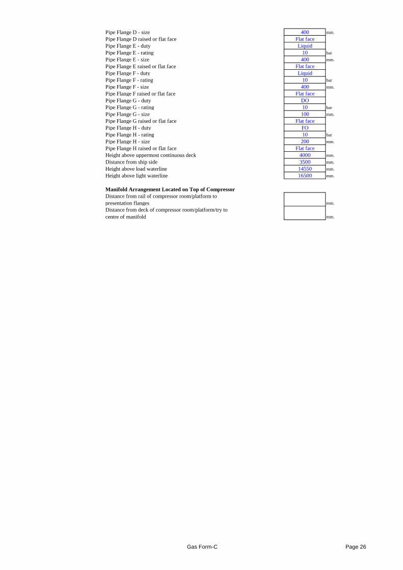
Pipe Flange D - size 400 mm.
Pipe Flange D raised or flat face Flat facePipe Flange E - duty LiquidPipe Flange E - rating 10 bar
Pipe Flange E - size 400 mm.
Pipe Flange E raised or flat face Flat facePipe Flange F - duty LiquidPipe Flange F - rating 10 bar
Pipe Flange F - size 400 mm.
Pipe Flange F raised or flat face Flat facePipe Flange G - duty DOPipe Flange G - rating 10 bar
Pipe Flange G - size 100 mm.
Pipe Flange G raised or flat face Flat facePipe Flange H - duty FOPipe Flange H - rating 10 bar
Pipe Flange H - size 200 mm.
Pipe Flange H raised or flat face Flat faceHeight above uppermost continuous deck 4000 mm.
Distance from ship side 3500 mm.
Height above load waterline 14550 mm.
Height above light waterline 16500 mm.
Manifold Arrangement Located on Top of CompressorDistance from rail of compressor room/platform to presentation flanges mm.
Distance from deck of compressor room/platform/try to centre of manifold mm.
Gas Form-C Page 26
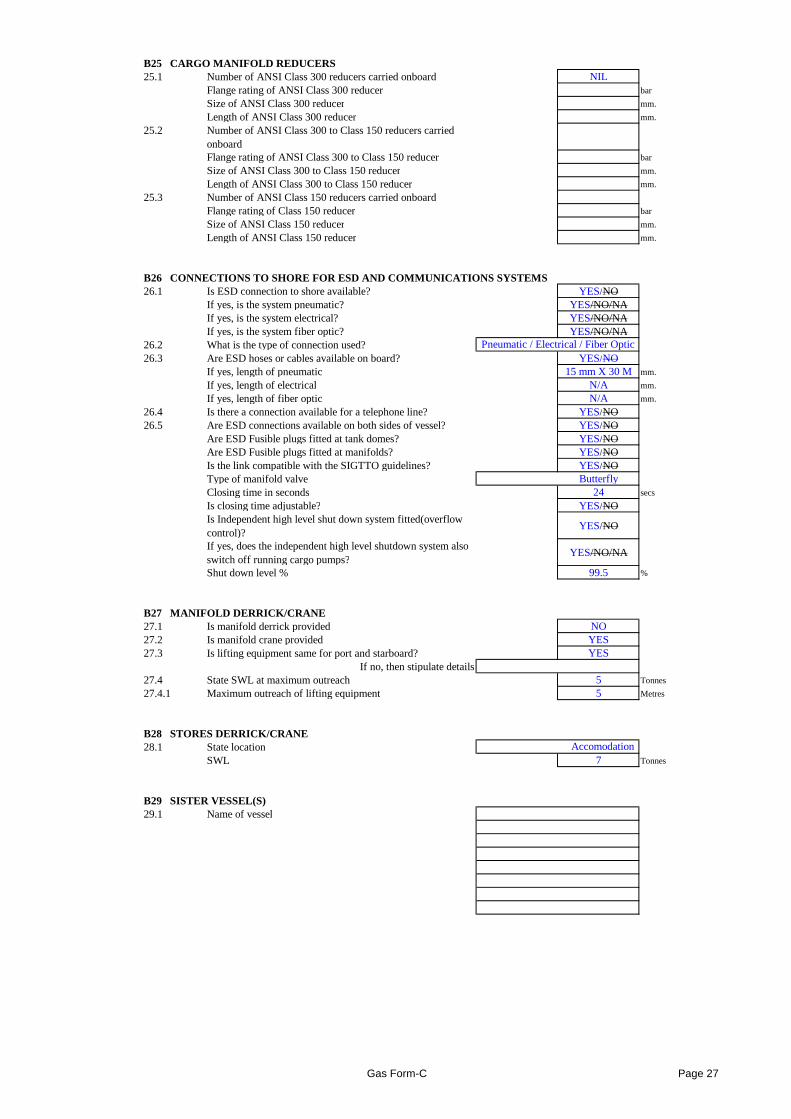
B25 CARGO MANIFOLD REDUCERS25.1 Number of ANSI Class 300 reducers carried onboard NIL
Flange rating of ANSI Class 300 reducer bar
Size of ANSI Class 300 reducer mm.
Length of ANSI Class 300 reducer mm.
25.2 Number of ANSI Class 300 to Class 150 reducers carried onboardFlange rating of ANSI Class 300 to Class 150 reducer bar
Size of ANSI Class 300 to Class 150 reducer mm.
Length of ANSI Class 300 to Class 150 reducer mm.
25.3 Number of ANSI Class 150 reducers carried onboardFlange rating of Class 150 reducer bar
Size of ANSI Class 150 reducer mm.
Length of ANSI Class 150 reducer mm.
B26 CONNECTIONS TO SHORE FOR ESD AND COMMUNICATIO NS SYSTEMS26.1 Is ESD connection to shore available? YES/NO
If yes, is the system pneumatic? YES/NO/NAIf yes, is the system electrical? YES/NO/NAIf yes, is the system fiber optic? YES/NO/NA
26.2 What is the type of connection used?26.3 Are ESD hoses or cables available on board? YES/NO
If yes, length of pneumatic 15 mm X 30 M mm.
If yes, length of electrical N/A mm.
If yes, length of fiber optic N/A mm.
26.4 Is there a connection available for a telephone line? YES/NO26.5 Are ESD connections available on both sides of vessel? YES/NO
Are ESD Fusible plugs fitted at tank domes? YES/NOAre ESD Fusible plugs fitted at manifolds? YES/NOIs the link compatible with the SIGTTO guidelines? YES/NOType of manifold valve ButterflyClosing time in seconds 24 secs
Is closing time adjustable? YES/NOIs Independent high level shut down system fitted(overflow control)?
YES/NO
If yes, does the independent high level shutdown system also switch off running cargo pumps?
YES/NO/NA
Pneumatic / Electrical / Fiber Optic
switch off running cargo pumps?Shut down level % 99.5 %
B27 MANIFOLD DERRICK/CRANE27.1 Is manifold derrick provided NO27.2 Is manifold crane provided YES27.3 Is lifting equipment same for port and starboard? YES
If no, then stipulate details27.4 State SWL at maximum outreach 5 Tonnes
27.4.1 Maximum outreach of lifting equipment 5 Metres
B28 STORES DERRICK/CRANE28.1 State location
SWL 7 Tonnes
B29 SISTER VESSEL(S)29.1 Name of vessel
Accomodation
Gas Form-C Page 27