Embed Size (px)
Citation preview

I
United States Department of Agriculture
Forest Service
Technology amp Development Program
7700mdashTransportation Management September 2000 0077 1801mdashSDTDC
SOIL BIOENGINEERING
An Alternative for Roadside
FOREST SERVICE
DE P A RTMENT OF AGR CULT
U RE Management
A Practical Guide
SOIL BIOENGINEERING
Soil Bioengineering An Alternative
for Roadside Management
A Practical Guide
Lisa Lewis Soil Scientist
National Riparian Service Team USDA Forest Service
September 2000
San Dimas Technology amp Development Center
San Dimas California
Information contained in this document has been developed for the guidance of employees of the Forest Service USDA its contractors and cooperating Federal and state agencies The Department of Agriculture assumes no responsibility for the interpretation or use of this information by other than its own employees The use of trade firm or corporation names is for the information and convenience of the reader Such use does not constitute an official evalution conclusion recommendation endorsement or approval of any product or service to the exclusion of others that may be suitable
The US Department of Agriculture (USDA) prohibits discrimination in all its programs and activities on the basis of race color national origin sex religion age disability political beliefs sexual orientation or marital or family status (Not all prohibited bases apply to all programs) Persons with disabilities who require alternative means for communication of program information(Braille large print audiotape etc) should contact USDArsquos TARGET Center at (202)720-2600 (voice and TDD)
To file a complaint of discrimination write USDA Director Office of Civil Rights Room 326-W Whitten Building 1400 Independence Avenue SW Washington DC 20250-9410 or call (202) 720shy5964(voice and TDD) USDA is and equal opportunity provider and employer
SOIL BIOENGINEERING
CONTENTS INTRODUCTION
Purpose and Scope 1
Objectives 1
Benefits and Limitations 1
History of Soil Bioengineering 2
Basic Soil Bioengineering Concepts 5
Site Evaluation and Design Checklist 6
Project Planning and Implementation Checklist 6
Site Preparation 6
Project Work 7
Plant Materials 7
Plant Movement Guidelines 8
Gene Pool Conservation Guidelines 8
TECHNIQUES FOR PROJECT IMPLEMENTATION
Native Plant Cuttings and Seed Collection 9
Salvaging and Transplanting Native Plants 11
Planting Containerized and Bare Root Plants 12
Distribution of Seed Fertilizer and Certified Noxious Weed-free Straw or Hay 13
Live Staking 14
Installation of Erosion Control Blanket 16
Construction of Live Cribwalls 18
Live Fascine 23
Brushlayering 25
Willow Fencing Modified with Brushlayering 27
28
Live Gully Repair
Branchpacking
30
Vegetated Geotextile 31
Log Terracing 32
Bender Board Fencing 37
REFERENCES CITED 41
iii
SOIL BIOENGINEERING
MAP
Map 1 Seed zones 10
FIGURES Figure 1 Live stake 15
Figure 2 Installation of erosion control blanket 17
Figure 3 Installation of erosion control mat 18
Figure 4 Live cribwall construction 20
Figure 5 Live cribwall construction 20
Figure 6 Live cribwall construction 20
Figure 7 Live cribwall-stepped full half and
toelog construction 22
Figure 8 Live cribwall battered construction 22
Figure 9 Live fascines 24
Figure 10 Brushlayering and brushlayering with log terrace 26
Figure 11 Willow fencing modified with brushlayering 27
Figure 12 Branchpacking 29
Figure 13 Live gully repair 30
Figure 14 Vegetated geotextile 31
Figure 15 Log terrace installation 33
Figure 16 Log terrace construction 33
Figure 17 Anchoring and filling gaps 35
Figure 18 Removal of slope overhang 36
Figure 19 Bender board fencing 38
iv
SOIL BIOENGINEERING
DEDICATION To Clifford Gershom Jordan my grandfather who farmed 150 acres of southwest Georgiarsquos sandy clay loam soils with a team of mules never once using mechanized equipment And to his beloved helpmate my grandmother Rachel Culbreth Jordan also known as Miss Pinky From this land they grew and hand-harvested cotton peanuts and corn From their garden she canned fruits and vegetables creating the most beautiful art gallery I have ever seen her pantry Their spirits circle my every step
Heartfelt thanks to my parents Betty Jordan Phillips and Charles Andrew Phillipswhose loving guidance and support made possible my career as a soil scientist
To Dave Craig silviculturalist district ranger and mentor His artful management of the land and people will never cease to amaze me
And to Marsha Stitt whose support through this arduous task made possible this publication
ACKNOWLEDGEMENTS Special thanks to Larry Ogg and crew members of the Washington Conservation Corpswho provided a technical review and who contributed to the application and evolution of several soil bioengineering stabilization methods listed in this guide Their hard work creativity and enthusiasm led to the stabilization of over a thousand erosion sites on the Olympic Peninsula
The author would also like to acknowledge the following contributions Kevin Finney who provided information on the history of soil bioengineering as well as several photographs for the document Robbin Sotir provided a technical review furnished figures and photographs of several of the described techniques Mark Cullington also provided several of the USDA Forest Service photographs and Susan Clements and George Toyama provided valuable assistance in turning these many pages into a book
The author extends a thank you to the following individuals for the time they offered in review and comment Forrest Berg Dave Craig Mark Cullington Wayne Elmore Ellen Eubanks Kevin Finney Shannon Hagen Chris Hoag Susan Holtzman Steve Leonard Marcus Miller Tom Moore Kyle Noble Larry Ogg Janice Staats Ron Wiley and Janie Ybarra
The content of this publication must be credited to the work of Arthur von Kruedener Charles Kraebel Donald Gray and Robbin Sotirndashall pioneering soil bioengineering practioners
FORWARD Contents of this document are directed primarily to areas that have 30 inches or more annual precipitation However several techniques included in this guide can be used in semi arid and arid environments Work with vegetation and soil specialists to understand what plants you can use in these environments
v
SOIL BIOENGINEERING
INTRODUCTION Purpose and Scope Transportation systems provide tremendous opportunities and if properly located on the landscape with well-designed drainage features can remain stable for years with negligible affects to adjoining areas Roads however are often linked to increased rates of erosion and accumulated adverse environmental impacts to both aquatic and terrestrial resources
Transportation systems provide access and allow utilization of land and resources Development priorities usually emphasize access safety and economics while environmental concerns refer to operational and maintenance problems such as surface condition plugged drainage structures including ditchlines mass failures and surface erosion or reduced access
This is not new information to land managers Road maintenance personnel for example face a substantial task in maintaining roads under their jurisdiction Major storms resulting in significant increases in road related erosion events and impacts to adjoining resources have compounded their challenge
Objectives Considerable funds are expended annually in an effort to improve road conditions and adjoining resources Historically engineers relied primarily on hardconventional solutions or ldquonon-livingrdquo approaches for slope and landslide stabilization The purpose of this publication is to provide viable alternatives known as soil bioengineering This is not to argue one solution is better than the other but to provide additional alternatives and to encourage an integration of these two practices Land managers need all available tools to effectively do their jobs This publication is an effort to meet that need
Specifically this publication provides field personnel with the basic merits of soil bioengineering concepts
and gives examples of several techniques especially effective in stabilizing and revegetating upland roadside enviromentsThe information provided in this document is intended to stimulate additional interest for the reader to seek out and use other bioengineering publications
Benefits and Limitations Soil bioengineering is an excellent tool for stabilizing areas of soil instability These methods should not however be viewed as the sole solution to most erosion problems Soil bioengineering has unique requirements and is not appropriate for all sites and situations On certain surface erosion areas for example distribution of grass and forb seed mixes hydromulching or spreading of a protective layer of weed-free straw may be satisfactory and less costly than more extensive bioengineering treatments On areas of potential or existing mass wasting it may be best to use a geotechnically-engineered system alone or in combination with soil bioengineering Project areas require periodic monitoring On highly erosive sites maintenance of the combined system will be needed until plants have established Established vegetation canbe vulnerable to drought soil nutrient and sunlight deficiencies road maintenance sidecast debris grazing or trampling and may require special management measures to ensure longterm project success
Benefits of soil bioengineering include bull Projects usually require less heavy equipment
excavation As a result there is less cost and less impact In addition limiting hand crews to one entrance and exit route will cause less soil disturbance to the site and adjoining areas
bull Erosion areas often begin small and eventually expand to a size requiring costly traditional engineering solutions Installation of soil bioengineered systems while the site problem is small will provide economic savings and minimize potential impacts to the road and adjoining resources
1
SOIL BIOENGINEERING
bull Use of native plant materials and seed may provide additional savings Costs are limited to labor for harvesting handling and transport to the project site Indigenous plant species are usually readily available and well adapted to local climate and soil conditions
bull Soil bioengineering projects may be installed during the dormant season of late fall winter and early spring This is the best time to install soil bioengineered work and it often coincides timewise when other construction work is slow
bull Soil bioengineering work is often useful on sensitive or steep sites where heavy machinery is not feasible
bull Years of monitoring has demonstrated that soil bioengineering systems are strong initially and grow stronger with time as vegetation becomes established Even if plants die roots and surface organic litter continues playing an important role during reestablishment of other plants
bull Once plants are established root systems reinforce the soil mantel and remove excess moisture from the soil profile This often is the key to long-term soil stability
bull Soil bioengineering provides improved landscape and habitat values
History of Soil Bioengineering The following text is an excerpt from a paper presented by Kevin Finney Landscape Architect at the Eleventh Annual California Salmonid Restoration Federation Conference in Eureka California March 20 1993
Soil bioengineering is the use of live plant materials and flexible engineering techniques to alleviate environmental problems such as destabilized and eroding slopes streambanks and trail systems Unlike
other technologies in which plants are chiefly an aesthetic component of the project in soil bioengineering systems plants are an important structural component
The system of technologies which today we call soil bioengineering can be traced to ancient peoples of Asia and Europe Chinese historians for example recorded use of bioengineering techniques for dike repair as early as 28 BC Early western visitors to China told of riverbanks and dikes stabilized with large baskets woven of willow hemp or bamboo and filled with rocks In Europe Celtic and Illyrian villagers developed techniques of weaving willow branches together to create fences and walls Later Romans used fascines bundles of willow poles for hydroconstruction
China 28 BC Bundling live stems for use in riverbank and dike repair Kevin Finney
By the 16th Century soil bioengineering techniques were being used and codified throughout Europe from the Alps to the Baltic Sea and west to the British Isles One of the earliest surviving written accounts of the use of soil bioengineering techniques a publication by Woltmann from 1791 illustrated use of live stakes for vegetating and stabilizing streambanks (Stiles 1991 pii) About the same time other early soil bioengineers working in Austria were developing live siltation construction techniques planting rows of brushy cuttings in waterways for trapping sediment and reshaping channels
2
SOIL BIOENGINEERING
China Early 1900rsquos Bundling live stems for use in riverbank and dike repair Kevin Finney
Much of the development and documentation of soil bioengineering techniques since the Industrial Revolution has been done in the mountainous areas of Austria and southern Germany Extensive logging of the forests in the region resulted in increased environmental problems much like what we see in the United States today Such problems as extreme slope erosion frequent landslides and avalanches and severe streambank degradation required repair By the turn of the century European soil bioengineers had begun to find new applications for old folk technologies using them to develop methods to deal with the new environmental problems These early soil bioengineers mostly foresters and engineers by training began to study traditional techniques and to publish their work This compiled body of knowledge is where the soil bioengineering profession would develop in the following decades
Europe Early 1900rsquos Cutting and collection of live stems for soil bioengineering Kevin Finney
The biggest boost to development of new soil bioengineering techniques in Europe came as a result of political developments during the 1930rsquos Financial restrictions of pre-war years in Germany and Austria favored use of low cost local materials and traditional construction methods for public works projects Construction of the German Autobahn system during this time involved extensive applications of soil bioengineering technologies Use of indigenous materials and traditional methods was also consistent with spreading nationalist ideology In 1936 Hitler established a research institute in Munich charged
3
SOIL BIOENGINEERING
with developing soil bioengineering techniques for road construction (Stiles 1988 p59) Although this development work was lost a Livonian forester named Arthur von Kruedener the head of the institute continued to work in the field and is known in central Europe as the father of soil bioengineering
At the same time the Germans were establishing their research institute some of the most important early soil bioengineering work in the United States was being done in California Charles Kraebel working for the USDA Forest Service was developing his ldquocontour wattlingrdquo techniques for stabilizing road cuts Kraebel used a combination of bioengineering techniques including live stakes live fascines and vegetative transplants to stabilize degrading slopes in the National Forests of central and southern California His use of the term ldquowattlerdquo to describe his live fascine systems has stuck with us and continues to be used today Kraebelrsquos work was well documented in USDA Circular 380 published in 1936 Two years later the Soil Conservation Service now known as the Natural Resource Conservation Service (NRCS) began a study of bluff stabilization techniques along the shores of Lake Michigan That agencyrsquos work which included use of live fascines brush dams and live stakes was published in 1938 (Gray and Leiser 1982 p188)
USA 1930rsquos Installation of live fascines USDA
Publication
During the post-war period European soil bioengineers returned to studying developing and evaluating new techniques In 1950 a committee of soil bioengineers from Germany Austria and Switzerland was formed to standardize emerging technologies that became part of the German National System of Construction Specifications the DIN (Robbin B Sotir amp Associates Inc nd)
Arthur von Kruedenerrsquos book Ingenieurbiologie (Engineering biology) was published in 1951 and it was the mistranslation of the German title which gave us the English term we use today The use of the term bioengineering has caused some confusion and has proven problematic for researchers who find in this country the term most often refers to an area of medical research NRCS now refers to this work officially as ldquosoil bioengineeringrdquo a term which emphasizes the soil component of the system
German and Austrian soil bioengineers continued to perfect their techniques and to publish their work through the 1950rsquos and 60rsquos This was an important step in launching a more structural approach laying the foundation for development of the professional field of soil bioengineering In the United States two important projects were carried out in the 1970rsquos and 80rsquos These include Trials of Soil Bioengineering Techniques in the Lake Tahoe Basin designed by Leiser and others (1974) and Revegetation Work in Redwood National Park (Reed and Hektner 1981 Weaver et al 1987) Both of these studies have been well documented and provide important information about application of soil bioengineering techniques in the western United States
In 1980 Hugo Schiechtlrsquos Bioengineering for Land Reclamation and Conservation was published in Canada It presents for the first time in English the work of many important European soil bioengineers including Lorenz Hassenteufel Hoffman Courtorier and Schiechtl himself The book made technologies and history of their
4
SOIL BIOENGINEERING
development and applications accessible to the English speaking world In 1997 another Schiechtl book was published Ground Bioengineering Techniques for Slope Protection and Erosion Control To date his writings remain the most important work on soil bioengineering in the English language
Hugo Schiechtlrsquos Bioengineering for Land Reclamation and Conservation Kevin Finney
Subsequent publications including Gray and Leiserrsquos Biotechnical Slope Protection and Erosion Control and Sotir and Grayrsquos Soil Bioengineering for Upland Slope Protection and Erosion Reduction in the United States Gray and Sotirrsquos 1996 Biotechnical and Soil Bioengineering Slope Stabilization and the British Construction Industry Research and Information Associationrsquos Use of Vegetation in Civil Engineering have made bioengineering technologies better known in the engineering profession However there is still resistance to the techniques in many countries
Soil bioengineering approaches most often use locally available materials and a minimum of heavy equipment and can offer local people an inexpensive way to resolve local environmental problems The publicrsquos increased environmental consciousness often makes soil bioengineering solutions more acceptable than traditional ldquohardrdquo engineering approaches
Despite and maybe because of the differences in approach and philosophy between soil
bioengineering and other engineering methods of addressing environmental problems soil bioengineering technologies are especially appropriate today The scale and range of environmental problems require consideration of new technologies even when as illustrated earlier they are in fact centuries old
Basic Soil Bioengineering Concepts By knowing the climate and vegetation of an area it is possible to predict the nature of the soils There are however many exceptions resulting from differences in parent materials drainage slope and the time the soil has been exposed to these environmental conditions
Projects require more than site evaluation and measurement Design should consider the natural history and evolution as well as cultural and social uses of the surrounding landscape An awareness of these factors and how they shape present and potential future landscape is critical for project success Knowledge of current and future land management goals is also important A proposed soil bioengineering project within a forested landscape for example requires an understanding of the arearsquos geologic and glacial history itrsquos propensity for wild land fires wind storms and floods occurrence and trends of natural and management related erosion history of road construction methods and current maintenance practices sequence of vegetation removal and revegetation efforts and fire management history This information provides interesting lore and insight on the project arearsquos potential and capability
In addition to understanding landscape scale patterns it is important to observe trends within erosion sites Whether erosion occurs naturally or through human-induced activities a site begins to heal itself immediately upon ldquofailurerdquo In mountainous terrain for example wood may become embedded in the slope terracing eroding soils Once an angle of repose has been achieved
5
SOIL BIOENGINEERING
between these natural terraces vegetation begins to establish Herbaceous plants usually provide initial vegetative cover on these sites This initial cover also assists in establishment of soil microorganisms Typical succession patterns go from exposed ground through a herbaceous stage to pioneer shrub and tree and finally to a climax tree stage The primary goal is to examine and document these trends Soil bioengineering designs are intended to accelerate site recovery by mimicking or accelerating what is happening naturally
Site Evaluation and Design Checklist There are many soil bioengineering systems Selection of the appropriate technique or techniques is critical to successful restoration At a minimum consider the following
Climatic Conditions bull Precipitation types levels timing and
duration bull Temperatures including extremes
Topography and Aspect bull Slope gradient terrain shape elevation of
project area and direction of sun exposure Climates near the ground can vary considerably within short distances South facing valleys for example receive more direct sun rays causing higher soil temperatures increased evaporation more rapid snowmelt in the spring and generally drier conditions than on the more shaded north facing side This difference will influence erosion rates and the composition and vigor of vegetation
Soils bull Underlying substrate bull Root and water permeability moisture
holding capacity and nutrient availability bull Identify conditions above below or within
your project site which may have an affect on your project and incorporate these considerations into your design
Water bull If applicable stream and fish types affected
by the erosion site bull Location of natural drainage channels and
areas of overland flow from road surface bull Identify areas for safe water diversion bull Note condition of ditch line and culvert inlets
and outlets
Vegetation bull Plant types and amount growing within and
adjacent to the project site This is especially important to identify colonizing species
bull Locations for and preparation of future plant and seed collection
Erosion Process bull Type of mass wasting or surface erosion
features including seepage bull Source of eroding material road fill slope cut
slope landing etc bull Trend of sitendashimproving naturally remaining
uniform or worsening
Project Planning and Implementation Checklist Site Preparation bull Develop and implement a communication
plan to keep all involved interested and informed
bull Establish clear project objectives Have these objectives reviewedfuther developed and approved by participants including the local road manager
bull List all project phases Under each phase catalogue and schedule all work items For each work item list responsible party and the date their tasks must be completed Identify and resolve timing conflicts Build flexibility into the schedule
6
SOIL BIOENGINEERING
bull Sites often require earthwork prior to and during installation of a soil bioengineering system Timing conflicts can occur between scheduling heavy equipment hand labor work plant collection and use
bull Select the right equipment for the job
bull Identify and remove work hazards such as rocks boulders and tree stumps
bull Determine storage and staging areas and access routes for people and machinery to minimize site disturbance and improve efficiency
bull Ensure coordination between heavy equipment operator and handcrew
bull Temporarily divert excess water
bull Stockpile excavated soils for later use and retain or salvage existing vegetation for later use
bull Provide and maintain temporary surface erosion and sediment control measures
Project Work bull Before beginning the project conduct an
on-site field pre-work meeting At a minimum include those with vegetation and soils skills
bull Avoid earthwork in saturated soils Schedule heavy equipment work during periods of low precipitation
bull Collect plant materials during the dormant season Keep them protected from wind and heat Best results are obtained when installation occurs the same day materials are prepared however some believe greater success can be realized if stems are soaked in water five days prior to planting Further research shows that cut stems are still viable after being refrigerated several months prior to planting under the
proper temperature and humidity condition Although opinions differ on length of storage all agree proper storage and use are critical Protecting stems from wind and keeping them cool and moist are essential
bull Inspect project work daily ldquoYou get what you inspect not what you expectrdquo
Plant Materials Living vegetation is the most critical component of a soil bioengineered system Existing vegetation and knowledge of predisturbance and surrounding area plant communities can inform the designer of project limitations opportunities and long term ecological goals Work with local plant experts such as botanists and silviculturalists to select the most appropriate plant species for your project
Which plants to use are affected by the following factors
bull Site characteristics (topography elevation aspect soil moisture and nutrient levels)
bull Existing vegetation bull Intended role of vegetation in the project
such as rooting characteristics bull Growth characteristics and ecological relationships of the plants bull Availability bull Logistical and economic constraints
Plants which can resist mechanical stresses of erosion floods and landslideswhile developinga strongstabilizing root system are best suited for soil bioengineering applications Examples of riparian plants suitable for soil bioengineering work include but are not limited to willows dogwoodscottonwoods big leafmaples spruce cedars aspen and alders
Plants better suited for dryer and poorer soil conditions include bitter brush snowberrywhite pine lodgepole pine vine maple Douglas maple oceanspray red elderberry and salmonberry The best indicator of what plant materials one should consider
7
SOIL BIOENGINEERING
for a soil bioengineering project are the plants growing on or adjacent to the project site Work with local vegetation specialists to understand the limitations and opportunities encountered when stabilizing an erosion site
Most commonlyplant materials are chosen from among those available on the site or nearby Alternatively the soil bioengineer may find an area where the vegetation will be removed or salvaged for future development Logistical concerns are also important in the selection of plant material
A single species may serve the primary structural requirement of the vegetation in a soil bioengineered system However it is preferable to use a mixture of species with varying but complimentary characteristics Benefits of using multiple species include
bull Less susceptible to devastation by disease or pests
bull Offers combinations of deep and shallow rooting species and high and low elevation vegetation
bull Allows the system to respond to changes in site conditions
bull Offers greater diversity and habitat values
Plant Movement Guidelines The reason for setting plant movement guidelines is to increase likelihood of plants surviving growing to maturity and reproducing Chance of success is much greater if locally collected materials are used
Upland plant species Use local seed (collection) zones to identify where best to collect seed cuttings or plants A seed zone is an area having a defined boundary and altitudinal limits within which landform and climate are sufficiently uniform A silviculturalist or botanist will direct you to this source of information Map 1 provides an example of a seed zone map in Washington State
Based on climatic and physiographic information seed zones were developed in 1966 to reduce risk of maladaptating commercial tree species and to provide structure for commercial seed trade Each zone has geographic boundaries and is additionally divided into 500-foot elevation intervals Seed lots are coded by both seed zone and elevation band
When collecting seeds cuttings or plants for smaller projects (perhaps a one-time collection) the elevation band can extend approximately 250 feet above and below the site
Shrubs forbs grasses and riparian species Use watershed boundaries as seed cuttings and plant collection and transplant zones with500-foot elevation intervals Planting seeds cuttings or plants outside the seed zone or watershed should be done only after consultation with a silviculturist or botanist
Gene Pool Conservation Guidelines Just as important as plant movement guidelines are making sure the seed lots cuttings or plant lots are genetically diverse To prevent loss of genes in the population use a minimum of 30 to 50 unrelated donor plants Collecting equal number of seeds cuttings or plants from each donor plant or area will also ensure representation by as many parent plants as possible
Donor plants should also be separated by sufficient distance to reduce risk of relatedness ie originating from the same rhizome or root system or for outcrossing plants having one or both parents in common
8
SOIL BIOENGINEERING
TECHNIQUES FOR PROJECT IMPLEMENTATION
Native Plant Cuttings and Seed Collection Advantage Inexpensive Use of local stock Better adapted to local climate and soil conditions
Disadvantages Can have high mortality if collection and storage not performed correctly Can be expensive
Tools needed Hand pruners hand clippers untreated twine burlap sacks (moistened and lined with wet leaves or mulch) plastic sheeting
For seed collection Paper bags cool dry storage area
Procedure bull Collect from 30 to 50 parent plants in good
condition Never take more than 50 percent of seed or cuttings from a given area
bull Collect an equal number of seeds or cuttings from each plant
bull Use watersheds (and 500 foot elevation intervals) for collection of seeds or cuttings of shrubs forbs grasses and ripariantree speciesThe elevation band can be considered to extend approximately 250 feet above or below the site
bull For plant cuttings use young shoots (1 to 2 years old) Older and larger stems tend to have higher mortality Refer to Plant Materials section for information on preferred plant species
bull Protect cuttings fromwind bycovering with plastic sheeting Protecting stems from wind and keeping them cool and moist are essential
bull Seeds collected should be ripe or mature
Harvesting with loppers Robbin Sotir amp Associates
Harvesting with brushsaw Robbin Sotir amp Associates
Harvesting with chainsaw Robbin Sotir amp Associates
9
SOIL BIOENGINEERING
Note A seed zone is an area having a defined boundary and altitudinal limits within which landform and climate are sufficiently uniform Refer to map 1
Map 1ndashSeed zones
10
SOIL BIOENGINEERING
Salvaging plants USDA Forest Service
Salvaging and Transplanting Native Plants Advantage Inexpensive
Disadvantages Can have high mortality if salvaging and transplanting not performed correctly and timely Soil moisture deficiency and over exposure to air and heat are critical factors in plant mortality
For trees shrubs forbs and riparian species use watershed boundaries as collection zones with 500 foot elevation intervals The elevation band can extend approximately 250 feet above or below the site
Plants should be dormant during salvaging and transplanting
Tools needed A flat-bladed spade metal file (for sharpening the spade) hand clippers (for pruning) burlap sacks (moistened and lined with leaves or mulch) plastic sheeting
Procedure Salvaging bull Locate a small and healthy plant growing by itself
Trees and shrubs growing in clumps connected by underground runners are less likely to survive transplanting
bull Clear area around plant of leaves and twigs Shrubs can be pruned if they have a few long branches (over 4 feet) Have a moist burlap sack nearby lined with wet leaves or mulch
bull Dig in a circle approximately eight inches from the main stem A larger excavated area of one foot may be required if it is a large shrub or seedling (3 to 4 feet high) Gently work the spade under the plantrsquos roots and lift the root ball out on the shovel blade Immediately place the root ball into the moistened burlap sack If you are unable to remove entire root ball collect as much of the root system as possible It is especially critical to protect fine root hairs of the plant It is also important to protect excavated plants from direct air and heat exposure
Transplanting bull Salvaged plants should be planted within two hours
of lifting Keep plants moist and free from air and heat exposure
bull Holes should be dug overly large Recommendation is to dig two times the volume of root ball Larger holes will be required in ldquotighterrdquo soils If available add a small amount of low dose time-release fertilizer and mix into the soil Note For bareroot and container plants do not add fertilizer the first year Planting holes must be deep enough so the downslope side of the rootball is entirely buried
bull Roots should be carefully spread out so none are kinked or circling Protect roots especially fine root hairs on the main root system Add water if availablewhen the plant is half installed to reduce voids and increase root and soil contact If possible water when planting is completed
11
SOIL BIOENGINEERING
Planting vegetation USDA Forest Service
bull On-site soil should be used to backfill the hole Firmly tamp the soil around the plant Be careful not to over compact the soil Once transplanted prune the plant to conserve ldquofuelrdquo for root development Prune to balance tops with roots For example if you cut off roots cut back tops by about12 Use clippings as mulch around the plant
bull Transplanting a microsite Depending on site conditions and project objective it may be preferred to salvage and transplant a small section of ground This ground section usually contains several plants with roots seed soil soil microorganisms and duff materials This technique provides great benefits to the area trying to revegetate For transplanting small sections of ground excavate an area large enough to ldquoplantrdquo the entire piece Lay it in the excavated area and level with adjoining ground Use excavated soil to secure edges of transplanted piece Tap gently in place Whenever possible water the transplant
Planting Containerized and Bare Root Plants Advantages Best application for long term increase in mechanical strength of soils Can be quickly applied to slopes materials are inexpensive creates a rooting zone over time to protect soils from erosion
Disadvantages Can have high mortality if planting not performed correctly Soil moisture deficiency and over exposure to air and heat are critical factors in plant mortality
Containerized and bare root plants must be installed with careful attention to protect their root systems
Tools needed Hoedad or dibble tree planting bag water for root dipping of bare root plants
Procedure bull The planting hole should be dug deep and wide
enough to fully accommodate the natural configuration of the root system
bull The roots should be carefully spread out so none are kinked circling or jammed in the bottom of the planting hole
bull On-site soil should be used to backfill the hole and the plant firmly tamped but not overly compacted into the ground Add water if available to reduce voids that can desiccate roots
12
SOIL BIOENGINEERING
Distribution of seed and fertilizer USDA Forest
Distribution of Seed Fertilizer and Certified Noxious Weed-free Straw or Hay Advantages Can be quickly applied to slopes materials are inexpensive creates shallow fibrous rooting zone in the upper foot or so of the surface profile which binds near-surface soils and protects soil surfaces from surface water runoff wind and freeze-thaw erosive forces
Disadvantages Not adequate alone for mitigating highly eroded surface erosion areas or for landslide stabilization
Seeding should be applied in combination with planting trees and shrubs to provide root reinforceshyment of surface soils Best times to apply include spring and early autumn If project is implemented in autumn it is critical to allow adequate time for good root and leaf development (approximately 4 inches) prior to winter Refer to Natural Resource Conservation Service technical guide for seeding dates available in every US county
Spreading straw mulch USDA Forest Service
Seeding involves application of grass forb and woody plant seed mixes to erosion areas
Tools needed McLeod rake hand seeder protective respiratory mask
Procedure bull Round top edge of slope failure (fig 18) For
project success it is critical to address this ldquoinitiation pointrdquo or chronic source of the erosion A common initiation point for these failures is located at the upper boundary of the site For project success it is critical to remove or round off slope overhang (figure18)
bull Smooth all eroding areas such as rills or gullies In addition prepare a seed bed by slightly roughening area Do this by raking across slope face never downslope Raking downslope can create depressions for channeling water
Slope terracing USDA Forest Service
13
SOIL BIOENGINEERING
bull Create terraces on contour when slopes exceed 35 percent Dig these terraces 10 to 14 inches deep across slope face Spacing usually varies from 4 to 10 feet depending on conditions (fig 2) The objective is to accelerate establishment of plants by reducing slope angle and steepness between each terrace
bull Broadcast seed fertilizer and weed-free straw Make sure your seed is covered with at least 14 inch of soil Seed and fertilize as required by mix directions For example a mix may consist of 1 part seed (annual rye and forb mix) and 3 parts fertilizer (161616) Organic amendments in place of fertilizers also work well Work with local vegetation and soils specialists to determine desirable seed species and soil nutrient needs In addition determine if burying seed is critical for germination
bull Hand spreading of mulch is sufficient However machine application spreads materials more evenly and requires less mulch for full coverage As a result machine application may be more economical than hand distribution
bull In addition to mulching the site it is critical to protect areas from additional surface water flow specifically overland flow from roads Direct water flow away from the project area by constructing crossdrains across the road surface several feet prior to the project area Location and number of crossdrains needed will depend on several factors including road gradient and whether or not the road is outsloped or insloped above project area Crossdrains are cut approximately 6 inches deep across road surface to a vegetated stable point on the fillslope These hand-excavated drains are a temporary measure until heavy equipment is available to dig deeper water diversions An alternative to crossdrains or an additional measure to consider is to install drain rock and allow the water to move through the project area
Live staking Robbin Sotir amp Associates Live Staking Advantages Overtime a living root mat developes soil by reinforcing and binding soil particles together and by extracting excess soil moisture Appropriate technique for repair of small earth slips and slumps that usually have moist soils
Disadvantages Does not solve existing erosion problems (excluding benefits from associated mulch) live staking is not a short-term solution to slope instabilities
Tools needed Hand pruners and clippers untreated twine deadblow or rubber hammer burlap sacks (moistened and lined with wet leaves or mulch)
Procedure Vegetative cuttings are living materials and must be handled properly to avoid excess stress such as drying or exposure to heat They must be installed in moist soil and adequately covered with mulch Soil must be tamped to eliminate or minimize air pockets around buried stems
Installation is best accomplished in late fall at onset of plant dormancy in the winter as long as the ground is not frozen or in early spring before budding growth begins
Live staking involves insertion and tapping of live rootable vegetative cuttings (eg willow cottonwood
14
SOIL BIOENGINEERING
and red-osier dogwood) into the ground If correctly prepared and placed the live stake will root and grow
bull Live cuttings are usually 12 to 1 12 inches in diameter and 18 to 36 inches long Materials must have side branches cleanly removed and bark intact Young shoots 1 to 2 years of age work best Older and larger stems have a higher rate of mortality but can be successful with additional treatment eg bark scoring and rooting hormones
bull Cut basal end at an angle for easy insertion into the soil Cut top square (figure 1)
bull Best results are obtained when installation occurs the same day stakes are prepared however some believe greater success can be realized if stems are soaked in water 5 days prior to planting Further research shows that cut stems are still viable after being refrigerated several months prior to planting Although opinions differ on length of storage all agree proper storage and use are critical Protecting stems from wind and keeping them cool and moist are essential
bull Orient buds up
bull Tap live stake into the ground at right angles to the slope Installation may be started at any point on the slope face
bull Two-thirds to three-quarters of the length of the live stake should be installed into the ground and soil firmly packed around it after installation (figure 1) The more stem exposed to air the more moisture is lost This moisture is critical for root development
bull Install live stakes 2 to 3 feet apart using triangular spacing Density of installation should range from 2 to 4 live stakes per square yard
bull Be careful not to split stakes while tamping them into the ground Covering the stake with a 2 by 4-inch wood section will cushion the blows thus protecting the stake from splitting Trim damaged top area
bull Rebar can be used to make a pilot hole in firm soil Tamp the live stake into the ground with a deadblow (hammer filled with shot or sand) or rubber mallet
Figure 1ndashLive stake
14 to 13 ldquo Flat top
12 to 1-12 ldquo
18 to 36 ldquo
Angle
Bury 23 to
34 of stem
not to scale
15
SOIL BIOENGINEERING
Hand excavated terraces for erosion control blanket USDA Rolling out erosion control blanket USDA Forest Service Forest Service
Installation of Erosion Control Blanket Advantages Excellent for mitigating surface erosion The blanket offers immediate and uniform slope protection from rain and overland water flow if it is installed in full contact with the soil surface
Disadvantages Can be labor intensive and expensive Requires numerous wood stakes or livestems Too much grass within the blanket will lead to over competition for moisture sunlight and nutrients and may result in high tree and shrub mortality
Installation of erosion control blankets involves site preparation trenching application of grass andor forb seed mix and fertilizer and installation of fabric This technique is suitable for treating surface erosion areas especially fillslopes where there is a concentration of surface water runoff (figure 3)
Tools needed McLeod rake hand seeder 6-inch spikes and 2-inch pieces of rubber or fire hose hand prunners and clippers heavy duty scissors deadblow or rubber hammer
Procedure bull Round top edge of slope failure (figure 18) For
project success it is critical to address initiation point or chronic erosion source of the slope failure The common initiation point for these
failures is located at the upper boundary of the site For project success it is critical to remove and or round off slope overhang (figure 18)
bull Smooth all eroding areas such as rills or gullies In addition roughen entire site Do this by raking across and not downslope Raking downslope can lead to channeling water
bull Create a small berm on road edge (figure 2)
bull Excavate terraces 10 to 14 inches deep and 5 feet apart (figure 2)
bull Broadcast seed and fertilizer on treatment area as required by mix directions An example one seed mix may include 1 part annual rye and 3 parts 161616 fertilizer Organic amendments can be used in place of inorganic fertilizers
bull Roll out blanket parallel with road between trenches Fabric edges should lay evenly across bottom and top trenches Begin matting installation at bottom two trenches (figure 2)
bull Follow these directions for remaining rows The upper row of fabric should overlap the lower row Lay edge of top row of fabric into shallow terrace created while excavating the berm at road edge (figure 2)
16
SOIL BIOENGINEERING
bull To secure fabric into road edge nail 60D spikes through a hose piece washer If road surface is not too compacted use dead wood stakes instead of nails Nail or stake every 3 to 4 feet across top row of fabric at road edge (figure 2) Once nailed rake bermed soil back over matting edge Note Check with road manager to ensure maintenance activities will not require blading road edge at fabric site Road blading would lead to tearing out sections of the project If this is a major concern install upper edge of fabric a few 4 to 6 inches below the road edge
bull To secure fabric to slope face install live stakes into fabric across slope and through terraces
Optimum spacing of these stakes ranges from 2 to 3 feet Maximum spacing between stakes should not exceed 4 feet (figure 3)
bull Tamp live stakes in leaving 14 to13 of stem above ground and 34 to 23 below ground (figure 1) Trim stakes if more than 13 is exposed Average length of stake ranges from 18 to 36 inches Stakes should be flatcutontopand diagonalcuton bottom so they will be installed correctly and easily (figure 1) Remove top sections of stakes damaged during installation If you are not working in moist soil eg riparian area the willows will not survive In these cases it would be more cost effective to use wood stakes instead
CutslopeShallow terrace
6rdquo berm
Cutslope
Nail and washer 3rsquo to 4rsquo apart
Roadbed
Overlap matting on terraces
Terrace 10rdquo to 14rdquo deep
5rsquo ft
Matting
5rsquo ft
Roadbed
not to scale
Figure 2ndashInstallation of erosion control blanket
17
SOIL BIOENGINEERING
Roadbed Terraces
Side view
Terrace
Nails or stakes Roadbed
Nails or stakes
Terrace
not to scale
Live cribwall one month after construction USDA Forest Service
Figure 3ndashInstallation of erosion control mat
Construction of Live Cribwalls Advantages Appropriate at base of a cut or fillslope where a low wall or log may be required to stabilize toe of the slope and reduce slope steepness Useful where space is limited and a more vertical structure is required Provides immediate protection from erosion while established vegetation provides long term stability Aesthetically more pleasing and possibly less expensive compared to conventional gabion baskets
Disadvantages Not designed for or intended to resist large lateral earth stresses Depending on soil quality of cutslope may have to use commercial fill material Can be labor intensive and expensive to construct Can have high mortality if willow stems are not collected when dormant not cut and used the same day or mishandled in transfer
A live cribwall consists of a hollow box-like interlocking arrangement of untreated log or timber members The structure is filled with suitable backfill material and
18
SOIL BIOENGINEERING
Live cribwall during construction USDA Forest Service
layers of live branch cuttings such as willow or dogwood which root inside the crib structure and extend into the slope Cribwall should be tilted or battered back if constructed on a smooth evenly sloped surfaceOnce live cuttings root and become established subsequent vegetation gradually takes over the structural functions of wood members (figure 8) Coordinate with road manager prior to construction Often their primaryconcern is the structure will block water flow in the ditch line Make sure the design takes this concern into consideration
Basic design ideas are from Sotir and Gray 1982 and 1992 The following description and guide however includes several changes
Tools needed Chainsaw McLeod rake deadblow or rubber hammer 8 to 12 inch spikes or rebar shovels hand prunners and clippers
Procedure A Starting at lowest point of the slope excavate
loose material until a stable foundation is reached
B Place first course of 4 to 8 inch diameter logs or timbers at front and back of excavated foundation approximately 4 to 5 feet apart and parallel to the slope contour These are your main beams (figure 4)
C Lay 4 to 5 foot long and 4 to 8 inch diameter cross beams (either conifer or hardwood) across
main beams Spike or wire cross beams to main beams front and back (figure 5)
D Fill inside of main frame with soil Note Some gravel and rock can be used however willows will have more vigor if soil conditions are favorable If consequence of project failure is high it is critical to use commercial fill material
E Lay 5 foot long and 12 to 3 inch diameter trimmed live cut branches (3 to 6 inches apart depending on soil moisture) between cross beams and into cutbank On the bottom layer lay the basal ends of live cut branches under back main beam and on top of front main beam (figure 5 and figure 6) Note The purpose is to take full advantage of excess water at slope base If you do not have excess soil moisture conditions you do not have to lay butt ends of branches under back main beam Instead you can lay them directly over this beam
F Following ldquoArdquo and ldquoBrdquo start second layerThe onlydifference is set main beams back the width of bottom main beams and into cutbankThis allows cribwall to lean into cutbank and keeps fill material from falling out of front of cribwall (figure 7)
G Fill frame with soil
H Lay 4 to 5 foot long live cut branches on top of front and back main beams and between cross beams Lay these live branches approximately 3 inches apart (figure 5) Spacing of branches depends on availability of moisture and can range from side-by-side to 6 inches apart
I Continue constructing layers following ldquoErdquoldquoFrdquo and ldquoGrdquo until you reach specified height
J If needed construct wings or flanges to catch soil at structurersquos edges and to key in the structure to the slope face
19
main
ain b
SOIL BIOENGINEERING
K Cribwall should be tilted back if constructed on a smooth evenly sloped surface This can be accomplished by excavating the back of the stable foundation (closest to the slope) slightly deeper than the front to add stability to the structure (figure 8)
L May be constructed in a stair-stepped fashion with each successive layer of timbers set back 6 to 9 inches toward back cut slope face from previously installed course
Half Cribwall bull To insure minimum road width of 14 feet it
may be necessary to construct a half cribwall This is done by cutting cross beams width in half from 4 to 2 feet wide at base of cribwall (figure 7) and gradually increasing cribwall width by layer as desired cribwall height is being achieved (figure 7 and figure 8)
Toe Log Technique bull The toe log technique is a handy tool for very
small cutslope erosion features eg 10 feet high by 15 feet wide Place a 20 to 24 inch diameter log along the base of the erosion site Lay 5 foot long and 12 to 1 inch diameter live cut branches (side-by-side to 6 inches apart depending on soil moisture) on top of the log and into cutbank (figure 7) The purpose is to take full advantage of excess water at slope base Place soil behind the log with soils from the slope face Toe logging is a quick and effective tool in stabilizing base of slopes However it is only effective when sites are small and only slightly over steepened It is very important to use the right size log for existing slope condition
When constructing a live cribwall half cribwall or toe log the initiation point of the slope failure must be addressed The common initiation point or source of chronic erosion for these failures is located at the upper boundary of the site For project success it is critical to remove or round off slope overhang (figure 18)
Rear beam
Front m eam
Cutslope
Edge of cutbank
Road
For half cribwall
Ditch
20
not to scale
4-8 diameter
Figure 4ndashLive cribwall construction
20
SOIL BIOENGINEERING
Rear main beam
Front main beam
Cutslope
Edge of cutbank
Road
3 apart
Ditch
not to scale
4 to 8
20
5 long
8 to 12spike
12 to 3 diameter 5 in length
4-8 diameter
Figure 5ndashLive cribwall construction
Crossbeam
Back mainbeam
Spikes Ditch
Roadbed
Cutslope
Willow on top of front main beam
Willow under rear main beam
Existing roadbed
not to scale
Figure 6ndashLive cribwall construction
21
SOIL BIOENGINEERING
3rsquo to 5rsquo
Constructed into slope
minimum of 6rsquo 8 to 12rdquo
Ditch
Roadbed
Half cribwall
1-12 to 3rdquo 4rsquo diameter
Ditch
Roadbed Ditched
Toe log 20-24rdquo diameter 2rsquo
Figure 7ndashLive cribwall-stepped full half and toelog construction
Evacuated cutslope
New slope
Roots
5rsquo to 6rsquo
Soil
Ditch Roots
Figure 8ndashLive cribwall battered construction
22
SOIL BIOENGINEERING
Live facines illustration Kraebel Live Fascine Advantages Immediately reduces surface erosion or rilling Suited to steep rocky slopes where digging is difficult Capable of trapping and holding soil on the slope face thus reducing a long slope into a series of shorter steps Can also be used to manage mild gully erosion and can serve as slope drains when bundles are angled Best suited for moist soil conditions Note Where soil moisture is not sufficient for supporting live materials fascines can also be constructed of plant stems not intended for rooting The bundle still traps and holds sediments and reduces slope length and steepness between terraces Plant vegetation on andor between the terraces As inall projects living recovery is dependent on successfully establishing the vegetation
Disadvantages On steep or long slope lengths high runoff velocities can undermine live fascines near drainage channels Significant quantity of plant material is required and can dry out if not properly installed Best suited for riparian moist soil conditions Otherwise high plant mortality could occur
Live fascines (Kraebel1936 and Sotir and Gray1982 and 1996) also referred to as contour or willow wattling are long bundles of branch cuttings bound together into sausage like structures (figure 9)
Tools needed Hand pruners and clippers untreated twine (not hemp) pulaski or hazel hoe deadblow or rubber mallet McLeod rake dead plant materials
Procedure bull Excavate 10 to 14 inch deep terraces along slope
contour and the full width of treatment area Spacing of terraces averages between 5 to 7 feet with a goal of 11 slope Terrace placement is a function of slope and should be calculated Terrace excavation and live fascine installation should progress from base of project up to slope crest
bull Bundle willow branches Other species such as red-osier dogwood or snowberry can be used For best results cut and use plant materials same day (See comments in Live Staking about collection and timing of installation) Butt ends and top ends are usually laid alternately until a bundle has been created which looks like an 8 to10 inch wide sausage Plant materials should be about 12 to 5 inches in diameter and about 4 to 8 feet in length (figure 9) Bundles are then tied together using up to 20 percent dead material and bound with untreated lengths of twine Note Use of up to 20 percent dead materials retains structural properties of live fascine and bundle still has enough live material to grow
bull Lay bundle across terrace splice together ends of each (figure 9) and do not overlap Bundles should be 14 to 13 exposed
Live facine installation USDA Forest Service
23
SOIL BIOENGINEERING
Live facine installationndashangled Robbin Sotir amp Associates
bull Next live stake the downslope side of terraces at middle and overlap points to hold live fascines in the terrace Be sure to splice ends of bundles In addition place wood stakes through live facines every two feet Wood stakes should be driven directly through bundle center (figure 9) Live willow and wood stakes should be 1 to 3 inches in diameter and 2 to 3 feet long Stakes should be flat cut on top and diagonally cut on bottom to ensure appropriate and easy installation Remove top section of live stakes damaged during installation
bull Stand in completed terrace and begin excavation of second terrace This process will allow soil from second terrace to cover first row Walk on wattles to compact and to gain good soil fascine contact
bull If available water fascine to work soil into the bundle for increased soil contact and decreased desiccation
bull Move upslope to next terrace alignment and repeat process (figure 9)
1
2
3
Untreated Twine Ties
Stems 12 to 1-12 diameter 8 to 10 diameter
4 to 8 length not to scale
Live facine Wood stake
Live stake
Spacing averages 5rsquo to 7rsquo
face measurement
Figure 9ndashLive fascines
24
SOIL BIOENGINEERING
Brushlayering Advantages Breaks up slope length into a series of shorter slopes separated by rows of brushlayer Reinforces soil as roots develop adding resistance to sliding or shear displacement Reinforces soil with unrooted branch stems Provides slope stability and allows vegetative cover to become established Traps debris on slope Aids infiltration on dry sites Dries excessively wet sites
Disadvantages Recommended on slopes up to 21 in steepness and not to exceed 15 feet in vertical height Labor intensive
Brushlayering (Sotir and Gray 1982 and 1992) consists of placing live branch cuttings in small terraces excavated into the slopeTerraces can range from 2 to 3 feet wide This technique is similar to live fascine systems because both involve cutting and placement of live branch cuttings on slopes The two techniques differ in the orientation of the branches and depth they are placed in the slope In brushlayering cuttings are oriented perpendicular to slope contour (figure 10) This placement is more effective fromthe pointof view of earth reinforcement and mass shallow stability of the slope
Tools needed Hand pruners and clippers untreated twine (not hemp) pulaski or hazel hoe shovel deadblow or rubber hammer McLeod rake
Digging terraces for brushlayer installation Robbin Sotir amp Associates Brushlayer installation Robbin Sotir amp Associates
Procedure bull Begin project at base of treatment area Excavate
terrace so that approximately 14 of average brush length extends beyond slope face Do not over excavate This technique can trigger soil movements during installation It is important therefore to perform installation in phases and to avoid excavating more area than is necessary to install plant materials (figure 10)
bull Lay an appropriate amount (ie 20 to 25 stems per yard) of single or multiple mix of live brush species along trench sidewall Length of stems can vary from 3 to 4 feet and diameter 12 to 3 inches (figure 10)
bull Stand in completed terrace and begin excavation of second terrace This process allows soil from second terrace above to cover first brushlayer row Compact and slightly mound soil behind brushlayers
bull Move upslope to next trench alignment and repeat process (figure 10)
Brushlayers modified with log terracing installing a short small log (figure 10) can modify brushlayers The log provides additional support to the brushlayer reduces slope angle and serves as a small terrace to ldquocatchrdquo rolling rocks rather than allowing them to roll down the slope and damage vegetation
25
Slope
Installation fall line
direction
SOIL BIOENGINEERING
Brushlayering just after installation Robbin Brushlayering 3 months after installation Sotir amp Associates Robbin Sotir amp Associates
Spacing averages 5-7
Stems 1 14 to 2
diameter
2
3
Spacing 4 to 10
Plant shrubs and trees throughout slope face
To reduce slope angle Live branch cuttings
Log (4 to 6 diameter)
Brushlayer
Length = 2 to 6
Stake
Brushlayer with log terrace
not to scale
Figure 10ndashBrushlayering and brushlayering w log terrace
26
SOIL BIOENGINEERING
Willow fencing with brushlayering USDA Forest Service
Willow Fencing Modified with Brushlayering Advantages These structures reduce slope angle providing a stable platform for vegetation to establish Willow fences trap rolling rocks and sliding debris and protects vegetation growing lower on the slope Willow fences provide support for small shallow translational or rotational failures Sites where fine textured soils can provide ample summer moisture or where seepage of groundwater provides moisture are suitable for willowbrushlayering fence installations These structures can also be constructed on dryer sites however expect high willow mortality In these situations the willow shelf is considered a temporary planting platform It is important therefore to establish deeper rooting shrubs and trees within the shelf When the structure begins to decay root systems of other plants will serve as the permanent feature
Disadvantages Significant quantity of plant material is required Moist site conditions are required for the fence to sprout and grow
Willow fencing with brushlayering is essentially a willow fence supported on a short brushlayer Specifically it is a short retaining wall built of living cuttings with a brushlayer base (figure 11) Willow fencing can also be used without base brushlayering (Polster 1998)
Tools needed Hand pruners and clippers pulaski or hazel hoe McLeod rake deadblow or rubber hammer wood stakes or rebar
Procedure Brushlayering bull Begin project at base of treatment area Excavate
16 to 20 inch deep trenches along slope contour and for full width of treatment area Spacing of trenches averages between 5 to 8 feet full measurement depending on site conditions This technique can cause additional erosion during installation therefore it is important to construct project in phases and to avoid excavating more area than is necessary to install plant materials (figure 11)
12 to 2 diameter
Willow fencing
18 to 36 long stakes 2 to 3 diameter
Brushlayer
18 to 36 long cuttings 1 2 to 2 diameter
Figure 11ndashWillow fencing modified with brushlayering
27
SOIL BIOENGINEERING
bull Lay live brush stems along base of trench Length of stems average 16 inches in length and diameter of 12 to 2 inches Approximately 14 of average brush length should extend beyond slope face (figure 10)
Willow fencing bull Install supporting 18 to 36 inch long wood
stakes cuttings or rebar Average diameter of stakes ranges from 2 to 3 inches
bull Place a few shrub cuttings 18 to 36 inch long and 12 to 2-inch diameter cuttings behind these supports
bull Place enough soil behind these supports to hold the shrub cuttings in place
bull Stand in the trench and begin excavation of second row This process will allow soil from second trench to cover first willow fencing brushlayer row
bull Compact and slightly mound soil on brushlayer and behind willow fence
bull As more soil is added add additional cuttings until the final height of the fence is achieved A goal should be to construct a 21 slope or less between the top of the willow fence and the bottom of the one above
bull Move upslope to next trench alignment and repeat process (figure 11)
Branchpacking just after installation Robbin Sotir amp Associates
Branchpacking Advantages As plant tops grow branchpacking system becomes increasingly effective in retarding runoff and reducing surface erosion Trapped sediment refills localized slumps orholeswhile roots spreadthroughout the backfill and surrounding earth to form a unified mass (figure 12)
Disadvantage Not effective in slump areas greater than 4 feet deep or 5 feet wide
Branchpacking (Sotir and Gray 1992) consists of alternating layers of livebranch cuttings and compacted backfill to repair small localized slumps and holes (figure 12)
Tools needed Hand pruners and clippers deadblow or rubber hammer untreated twine McLeod rake shovel wood stakes
Branchpacking just after installation Robbin Sotir amp Associates
28
SOIL BIOENGINEERING
Branchpacking post installation Robbin Sotir amp Associates
Procedure bull Starting at lowest point drive wooden stakes
vertically 3 to 4 feet into the ground Set them 1- to 1 12 -feet apart Wooden stakes should be 5 to 8 feet long and made from 3-to-4 inch diameter poles or 2 by 4 lumber depending upon depth of particular slump or hole
bull Place a layer of live cut branches 4 to 6 inches thick in bottom of hole between vertical stakes and perpendicular to the slope face (figure 12) Crisscross branches with growing tips generally oriented toward slope face Some basal ends of branches should touch the back of the slope
bull Install subsequent layers with basal ends lower than the growing tips of the branches This is to insure developing root systems will be located at water collection points on the slope
bull Each layer of branches must be followed by a layer of compacted soil to ensure soil contact with branch cuttings
bull Final installation should match existing slope Branches should protrude only slightly from the filled face
bull The soil should be moist or moistened to insure live branches do not dry out
1 to 1-12
Live branch cuttings 14 to 2 diameter
Compact fill material
Wooden stakes 5 to 8 long 2 x 4 lumber driven 3 to 4 into undisturbed soil
4 to 6 inch layer of live branch cuttings laid criss cross and
touching back of hole
Live branch cuttings should protrude slightly from
backfill area
Several weeks or months later
spacing not to scale
Figure 12ndashBranchpacking
29
SOIL BIOENGINEERING
3 to 4 inch layer of live branch cuttings laid in crisscross and touching undisturbed soil on gully bed
Several weeks later
Live branch cuttings 1 to 2 in diameter
Compacted fill material 6 to 8 layer
Gully bed
Figure 13ndashLive gully repair
Live Gully Repair Advantages Offers immediate reinforcement to compacted soil reduces velocity of concentrated flow of water and provides a filter barrier to reduce rill and gully erosion
Disadvantages Limited to rills and gullies which are a maximum of 2-feet wide 1-foot deep and 15- feet long
Live gully repair (Sotir and Gray 1992) utilizes alternating layers of live branch cuttings and compacted soil to repair small rills and gullies Similar to branchpacking this method is more appropriate for repair of rills and gullies
Tools needed Hand pruners and clippers shovel McLeod rake untreated twine
Procedure bull Starting at lowest point of the slope place a 3shy
to 4-inch thick layer of live cut branches at lowest end of the rill or gully and perpendicular to the slope (figure 13)
bull Cover with 6-to 8-inch layer of soil
bull Install live cut branches in a crisscross fashion Orient growing tips toward slope face with basal ends lower than growing tips
bull Follow each layer of branches with a layer of compacted soil to ensure soil contact with live branch cuttings
30
SOIL BIOENGINEERING
Figure 14ndashVegetated geotextile
Vegetated Geotextile Advantages Retards rill and gully erosion stabilizes fill banks Is less expensive than other retaining walls such as gabion or Hilfiker baskets
Disadvantage Can be expensive if heavy equipment required
Synthetic or organic geotextile wrapped around lifts of soil with a mix of live branches placed between layers There are numerous opportunites of blending geotechnical-engineered systems with soil bioengineering The following is one example
Tools needed Backhoe geotextile hand pruners and clippers McLeod rake shovel untreated twine
Procedure bull Excavate lower edge of slope break and bench
backcut Compact the soil layer Note Structural integrity is dependent on compacted soil layers Even with mechanized firming soils support live cuttings
bull Lay first layer of geotextile down into the bench
bull Fill lowest lift with gravel fold back and stake securely
bull Fill subsequent layers with soil and layers of live cut branches (figure 10) and alternate with lifts (figure 14) Each layer must be compacted
bull The structure can be built with a vertical face or stair-stepped and sloped back into the hillside
31
SOIL BIOENGINEERING
Installation - cutslope stabilzation with log terracing USDA Forest Service
Log Terracing Advantages Logs create terraces reducing length and steepness of slope provides stable areas for establishment of other vegetation such as trees and shrubs
Disadvantages Labor intensive and with potential safety hazards
Tools needed Chainsaw PV pole blocks and cable power winch shackles and chokers pulaski Mcleod and shovel wood stakes hand pruner and clippers traffic control signs
Procedure bull The technique utilizes alternating terraced logs
to stop surface erosion on eroding slopes Stopping the erosion is critical for successful revegetation efforts Specifically log terracing shortens slope length and gradient between each structure providing stable planting areas throughout most of the slope face (figure 15)
bull Prior to beginning a log terracing project place traffic control signs several hundred feet on both sides of your project area Then climb slope to locate and remove potential safety hazards These hazards include loose tree root wads unstable rocks and boulders This inspection will also provide a different visual
perspective of the site This ldquotop-downrdquo viewpoint is usually the best place to formulate your project design
bull Begin log terracing at the base of the slope and work your way uphill This should prevent undercutting of any terrace or log you place above It also provides a stable and secure footing area for project work
bull Log terracing consists primarily of 3 main steps These steps include moving installing and anchoring logs to specified points on an eroding hillside
Moving bull Try not to cause any additional erosion or
damage log terraces you have already excavated This can be accomplished by setting up a skyline or carefully using a straight dragline with block and cable
Installation bull Use a minimum of 12-inch diameter logs
Sixteen or 20-inch diameter logs work best The most common error in log terracing is using logs that are too small in diameter
bull Use existing slope features such as tree stumps rock outcroppings or natural slope benches to secure one or both ends of the logs These natural features make project work easier safer and work better than stakes or rebar for keeping the log in place on the slope
bull Excavate terraces 13 the width of the log diameter deep and for full length of the log With rope (or cable) blocks and winch place the logs into position (figure 16)
Anchoring bull Depending on site conditions attempt to space
log terraces 10 to 20 feet apart
32
SOIL BIOENGINEERING
bull Anchor logs into the slope using 3-to 5-inch should be inserted into the ground Bend over diameter wood stakes or 34 inch rebar any excess rebar
bull Stake length should be 4 times the diameter of the log A 12-inch diameter log for example would require 48-inch long stakes and a 16shyinch diameter log 64-inch long stakes
bull Once in place drive stakes vertically into slope just below the log Two thirds of the stake should be driven into the ground These stakes should be spaced every 4 feet across the length of the log (figure 17) Another recommended technique is to drill holes through the log and anchor with rebar Two thirds of total length
bull When utilizing tree stumps and rock outcroppings for anchor points gaps may occur between log and soil surface This gap must be filled To do so excavate a trench uphill from the log and place a smaller log flush with the log structure (figure 17)
bull There are many possible patterns for log terracing The following 3 have proved useful for stabilization efforts (figure 15) Whatever pattern utilized it is absolutely critical no gaps exist between the log and soil surface
Erosion site Erosion site Erosion site
Retaining structure Retaining structure Retaining structure
15-20
15-20
Shortened slope distance 50 failure
width
Rock
20
Treestump
Staggered Pattern Ladder Pattern Building Block Pattern
not to scale
Figure 15ndashLog terrace installation
33
SOIL BIOENGINEERING
Staggered Using logs with lengths greater than 50 percent of the width of the erosion site These logs should overlap each other and be anchored into stable soils on either side of the failure site
Ladder Logs extend across full width of erosion site and should be anchored into stable soils on either side of failure site
Building block This method best mimics what happens naturally on an eroding slope Begin the project at the slope base This area is stable and will provide a secure base to build off of as you work your way up slope There is no set pattern Design and log placement pattern will evolve as the project progresses Be creative
bull Once the slope has been stabilized with log terracing it is critical to address the upper portion of the slope failure This area is often referred to as the slope overhang Addressing this area is critical since it is the source of the surface erosion Without removing this erosion source project success is unlikely Cut away the overhang so slope angle will allow seed to germinate and plants to establish Try to angle the slope to blend with the new slope gradient created with log terracing Often this will require a cut 5 to 6 feet upslope This is the most difficult portion of a log terracing project and will often result in removing vegetation This vegetation however can be transplanted to other areas on the slope
34
SOIL BIOENGINEERING
Use of existing slope features
Stump
Rock
Front view trench construction
Trench
Place log 13 of diameter deep
Slope
Place log 13 of diameter deep
Trench construction side view
Stakes
not to scale
Figure 16ndashLog terrace construction
Formula A 12 diameter log needs 48 long stakes
Trench
Stake 13 above
Stake 23 below
Stakes
Front view
Erosion site
Log
Cutslope
Roadbed
Vertical placement
Side view
Erosion site
Stake 13 above ground
Stake 23 below ground
Ground level
Gap
Ground level
Filler log
not to scale
Figure 17ndashAnchoring and filling gaps
35
SOIL BIOENGINEERING
Roadbed Ditch
Cutslope
Fill slope
Slope overhang
Slope overhang
Area to remove
Area to remove
not to scale
Figure 18ndashRemoval of slope overhang
36
SOIL BIOENGINEERING
Bender Board Fencing Advantages These structures reduce slope angle providing a stable platform for vegetation to establish Like willow fencing bender board structures trap rolling rocks and sliding debris and protects vegetation growing lower on the slope Bender board fences provide support for small translational or rotational failures
Dry sites where soils receive very little precipitation this type of structure The bender board shelf is considered a temporary planting platform It is important therefore to establish deeper rooting shrubs and trees within the shelves When the structures begins to decay root systems of other plants will serve as the permanent feature
Disadvantage Significant quantity of plant material is required
Redwood or cedar bender board fencing is essentially a fence supported on a short layer of shrub or tree stems Specifically it is a short retaining wall built of redwood or cedar bender fencing with a stem layered base
Tools needed Hand pruners and clippers pulaski or hazel hoe McLeod rake deadblow or rubber hammer wood stakes
Procedure Stem Layered Base bull Begin project at base of treatment area Excavate a
24-inch deep terrace along slope contour and for full width of treatment area The back of the terrace should be dug with an approximate 70 degree angle To allow ample planting platforms space terraces about 5 feet apart
bull Lay 2 feet 6-inch long stems and 2 feet 6-inch long wood stakes (5050 mix) 2-inches apart and for full length of terrace Diameter can range from 12 to 2-inches Approximatly 6-inches will extend beyond slope face
Bender board Fencing bull Drive supporting 4 foot 6-inch (2 by 2) long stakes
2 to 3 feet into ground spaced 1 foot apart and perpendicular to the slope Rebar may be used instead of wooden stakes
bull Weave 10 foot long bender boards through these stakes until the wall reaches a height of 2 feet Once complete the bender board fence wall should be at a 15 degree angle to the slope Note As shown in photo some bender board are too brittle to weave
bull Once the wall frame is constructed carefully rake enough soil into the terrace to cover the stem layered base
37
SOIL BIOENGINEERING
bull Stand in terrace and begin excavation of second bull Move upslope to next terrace alignment and row This process will allow soil into the terrace repeat process to cover the stem layered base
bull A goal should be to construct a 21 slope or less between the top of the bender board fence wall and the bottom of the one above
10 foot long bender boards 14 thick 3-12 wide
2-6 long stakes spaced 3 apart
2 high seven bender boards
2 wide terraces spaced 5 apart
not to scale
4-6 post buried 2-3
Figure 19ndashBender board fencing
38
SOIL BIOENGINEERING
REFERENCES CITED
Bach David H and MacAskill IA 1984 Vegetation and Landscape Engineering Granada London
Bennett Francis W 1975 Methods of Quickly Vegetating Soils of Low Productivity Construction Activities US Environmental Protection Agency Washington DC
Brosius Myra 1985 ldquoThe Restoration of an Urban Stream Using Geomorphic Relationships and Biotechnical Streambank Stabilizationrdquo Athens GA University of Georgia Thesis
Chandler RJ 1991 Slope Stability Engineering Institution of Civil Engineers Thomas Telford Publishing Company
Chatwin S D Howes and D Swantson 1994 A Guide for Management of Landslide Prone Terrain in the Pacific Northwest Second edition Ministry of Forests Crown Publications Victoria BC
Christensen M and J Jacobovitch 1992 Revegetation Projects Everything You Wanted to Know About Live Staking Unpublished report for King County Dept of Public Works Surface Water Management Div Seattle WA
Coppin NJ and IG Richards 1990 Use of Vegetation in Civil Engineering Butterworths London England
Coppin Nick J and R Stiles 1989 The Use of Vegetation in Slope Stabilization Landscape Design with Plants Second Edition ed by Brian Clouston Boca Raton Florida CRC Press 212-234
Edlin HL 1949 Woodland Crafts in Britain BT London Batsford Ltd London
Finney Kevin P 1993 BioEngineering Solutions A Tool for Education Eugene OR University of Oregon Thesis
Finney K 1993 History of Soil Bioengineering Eugene OR Masters Thesis University of Oregon Thesis
Gray DR and AT Leiser 1982 Biotechnical Slope Protection and Erosion Control New YorkVan Nostrand Reinhold Company New York
Gray DH Leiser T Andrew and C A White 1980 Combined Vegetative Structural Slope Stabilization Civil Engineering 50(1)82-85
Gray D R and Sotir RB 1996 Biotechnical and Soil Bioengineering Slope Stabilization John Wiley and Sons Inc
Greenway DR 1987 Vegetation and Slope Stability In Slope Stability John Wiley and Sons Ltd Chapter 6
41
SOIL BIOENGINEERING
Johnson AW and JM Stypula eds 1993 Guidelines for Bank Stabilization Projects In the Rivetine Environments of King County County Department of Public Works Surface Water Management Division Seattle WA
Kraebel CJ 1936 Erosion Control on Mountain Roads USDA Circular No 380 Washington DC USDA
Kraebel CJ 1933 Willow Cuttings for Erosion Control Technical Note No 1 Berkely California USDA California Forest Experiment Station
Larson FE and WE Guse 1981 Propagating Deciduous and Evergreen Shrubs Trees and Vines with Stem Cuttings Pacific Northwest Coop Ext Pub PNW152
Leiser Andrew T J J Nussbaum Kay Burgess Paul Jack and W Thornhill 1974 Revegetation of Disturbed Soils in the Tahoe Basin California Department of Transportation Sacramento California
Lewis EA and LW Ogg 1993 Soil Bioengineering Project Descriptions Unpublished report for Olympic National Forest Hood Canal Hanger District
Leys Emil 1978 Wilhelm Hassenteufel 80 Years Old Garten und Landschaft in China Vol 4 Part 3 Cambridge The University Press
Maleike R and RL Hummel 1988 Planting Landscape Plants Wash State Univ Coop Ext Pub EB1505
Polster Environmental Services 1998 Soil Bioengineering for Forest Land Reclamation and Stabilization British Columbia Ministry of Forests
Robbin B Sotir amp Associates A Brief History of Soil Bioengineering Unpublished and undated manuscript
Schiechtl Hugo 1980 Bioengineering For Land Reclamation and Conservation Edmonton Canada The University of Alberta Press
Schiechtl H M and R Stern 1997 Ground Bioengineering Techniques for Slope Protection and Erosion Control Blackwell Science Publications ISBN 0-632-04061-0
Sotir RB and DH Gray 1992 Soil Bioengineering for Upland Slope Protection and Erosion Reduction Engineering Field Handbook Soil Conservation Service Chapter 18
Stiles Richard (172) 57-61 1988 Engineering with Vegetation Landscape Design (172) 57-61
Stiles Richard1991 Re-inventing the Wheel Landscape Design (203)
42
SOIL BIOENGINEERING
Weaver WE and MA Madej 1981 Erosion Control Techniques Used in Redwood National Park In Davies TRH and AJ Pearce eds Erosion and Sediment Transport in Pacific Rim Steeplands Washington DC Intrsquol Assoc Hydrological Sciences 640-654 IAHS-AISH Pub 132
Westmacott Richard 1985 The Rediscovered Arts of Twilling and Wattling Landscape Architecture 75(4)95-98
White Charles A and AL Frank S 1978 Demonstration of Erosion and Sediment Control Technology Lake Tahoe Region of California EPA-6002-78-208 Municipal Environmental Research Laboratory Office of Research and Development US Environmental Protection Agency Cincinnati Ohio
Ziemer RR 1981 Roots and the Stability of Forested Slopes In Davies TRH and AJ Pearce eds Erosion and Sediment Transport in Pacific Rim Steeplands
43
SOIL BIOENGINEERING
About the Authorhellip
Lisa Lewis graduated in 1987 from Fort Valley State University Fort Valley Georgia with a Bachelor of Science degree in Soil and Plant Sciences Lisa began her career with the Forest Service in August 1987 on the Hood Canal Ranger District She continued her career in the Pacific Northwest and since 1998 she has been a soil scientist with the National Riparian Service Team (NRST) As a member of the NRST Lisa provides training and technology transfer consulting and advisory services and program review for riparian restoration nationwide She specializes in road management issues and soil bioengineering techniques
Library Card
Lewis Lisa 2000 Soil bioengineeringmdashan alternative to roadside managementmdasha practical guide Technical Report 0077-1801-SDTDC San Dimas CA US Department of Agriculture Forest Service San Dimas Technology and Development Center 44 p
This publication provides field personnel with the basic merits of soil bioengineering concepts and gives examples of several techniques especially effective in stabilizing and revegetating upland roadside environments The information provided in this document is intended to stimulate additional interest for the reader to seek out and use these and other soil bioengineering applications
Soil bioengineering is the use of live plant materials and flexible engineering techniques to alleviate environmental problems such as destabilized and eroding slopes Unlike other technologies in which plants are chiefly an aesthetic component of the project in soil bioengineering systems plants are an important structural component
Keywords Soil bioengineering road management road maintenance restoration erosion native plant materials revegetation
Additional single copies of this document may be ordered from
USDA Forest Service San Dimas Technology and Development Center
ATTN Richard Martinez 444 E Bonita Avenue San Dimas CA 91773
Phone (909) 599-1267 x201 Fax (909) 592-2309
E-Mail rmartinezwo_sdtdcfsfedus FSNotes Richard MartinezWOUSDAFS
For additional technical information contact Lisa Lewis at the following address
USDA Forest Service National Riparian Service Team
3050 NE 3rd Street PO Box 550
Prineville OR 98854 Phone (541) 416-6788
E-Mail l3Lewisorblmgov
An electronic copy of this document is available on the Forest Servicersquos FSWeb
Intranet at httpfswebsdtdcwofsfedus

SOIL BIOENGINEERING
INTRODUCTION Purpose and Scope Transportation systems provide tremendous opportunities and if properly located on the landscape with well-designed drainage features can remain stable for years with negligible affects to adjoining areas Roads however are often linked to increased rates of erosion and accumulated adverse environmental impacts to both aquatic and terrestrial resources
Transportation systems provide access and allow utilization of land and resources Development priorities usually emphasize access safety and economics while environmental concerns refer to operational and maintenance problems such as surface condition plugged drainage structures including ditchlines mass failures and surface erosion or reduced access
This is not new information to land managers Road maintenance personnel for example face a substantial task in maintaining roads under their jurisdiction Major storms resulting in significant increases in road related erosion events and impacts to adjoining resources have compounded their challenge
Objectives Considerable funds are expended annually in an effort to improve road conditions and adjoining resources Historically engineers relied primarily on hardconventional solutions or ldquonon-livingrdquo approaches for slope and landslide stabilization The purpose of this publication is to provide viable alternatives known as soil bioengineering This is not to argue one solution is better than the other but to provide additional alternatives and to encourage an integration of these two practices Land managers need all available tools to effectively do their jobs This publication is an effort to meet that need
Specifically this publication provides field personnel with the basic merits of soil bioengineering concepts
and gives examples of several techniques especially effective in stabilizing and revegetating upland roadside enviromentsThe information provided in this document is intended to stimulate additional interest for the reader to seek out and use other bioengineering publications
Benefits and Limitations Soil bioengineering is an excellent tool for stabilizing areas of soil instability These methods should not however be viewed as the sole solution to most erosion problems Soil bioengineering has unique requirements and is not appropriate for all sites and situations On certain surface erosion areas for example distribution of grass and forb seed mixes hydromulching or spreading of a protective layer of weed-free straw may be satisfactory and less costly than more extensive bioengineering treatments On areas of potential or existing mass wasting it may be best to use a geotechnically-engineered system alone or in combination with soil bioengineering Project areas require periodic monitoring On highly erosive sites maintenance of the combined system will be needed until plants have established Established vegetation canbe vulnerable to drought soil nutrient and sunlight deficiencies road maintenance sidecast debris grazing or trampling and may require special management measures to ensure longterm project success
Benefits of soil bioengineering include bull Projects usually require less heavy equipment
excavation As a result there is less cost and less impact In addition limiting hand crews to one entrance and exit route will cause less soil disturbance to the site and adjoining areas
bull Erosion areas often begin small and eventually expand to a size requiring costly traditional engineering solutions Installation of soil bioengineered systems while the site problem is small will provide economic savings and minimize potential impacts to the road and adjoining resources
1
SOIL BIOENGINEERING
bull Use of native plant materials and seed may provide additional savings Costs are limited to labor for harvesting handling and transport to the project site Indigenous plant species are usually readily available and well adapted to local climate and soil conditions
bull Soil bioengineering projects may be installed during the dormant season of late fall winter and early spring This is the best time to install soil bioengineered work and it often coincides timewise when other construction work is slow
bull Soil bioengineering work is often useful on sensitive or steep sites where heavy machinery is not feasible
bull Years of monitoring has demonstrated that soil bioengineering systems are strong initially and grow stronger with time as vegetation becomes established Even if plants die roots and surface organic litter continues playing an important role during reestablishment of other plants
bull Once plants are established root systems reinforce the soil mantel and remove excess moisture from the soil profile This often is the key to long-term soil stability
bull Soil bioengineering provides improved landscape and habitat values
History of Soil Bioengineering The following text is an excerpt from a paper presented by Kevin Finney Landscape Architect at the Eleventh Annual California Salmonid Restoration Federation Conference in Eureka California March 20 1993
Soil bioengineering is the use of live plant materials and flexible engineering techniques to alleviate environmental problems such as destabilized and eroding slopes streambanks and trail systems Unlike
other technologies in which plants are chiefly an aesthetic component of the project in soil bioengineering systems plants are an important structural component
The system of technologies which today we call soil bioengineering can be traced to ancient peoples of Asia and Europe Chinese historians for example recorded use of bioengineering techniques for dike repair as early as 28 BC Early western visitors to China told of riverbanks and dikes stabilized with large baskets woven of willow hemp or bamboo and filled with rocks In Europe Celtic and Illyrian villagers developed techniques of weaving willow branches together to create fences and walls Later Romans used fascines bundles of willow poles for hydroconstruction
China 28 BC Bundling live stems for use in riverbank and dike repair Kevin Finney
By the 16th Century soil bioengineering techniques were being used and codified throughout Europe from the Alps to the Baltic Sea and west to the British Isles One of the earliest surviving written accounts of the use of soil bioengineering techniques a publication by Woltmann from 1791 illustrated use of live stakes for vegetating and stabilizing streambanks (Stiles 1991 pii) About the same time other early soil bioengineers working in Austria were developing live siltation construction techniques planting rows of brushy cuttings in waterways for trapping sediment and reshaping channels
2
SOIL BIOENGINEERING
China Early 1900rsquos Bundling live stems for use in riverbank and dike repair Kevin Finney
Much of the development and documentation of soil bioengineering techniques since the Industrial Revolution has been done in the mountainous areas of Austria and southern Germany Extensive logging of the forests in the region resulted in increased environmental problems much like what we see in the United States today Such problems as extreme slope erosion frequent landslides and avalanches and severe streambank degradation required repair By the turn of the century European soil bioengineers had begun to find new applications for old folk technologies using them to develop methods to deal with the new environmental problems These early soil bioengineers mostly foresters and engineers by training began to study traditional techniques and to publish their work This compiled body of knowledge is where the soil bioengineering profession would develop in the following decades
Europe Early 1900rsquos Cutting and collection of live stems for soil bioengineering Kevin Finney
The biggest boost to development of new soil bioengineering techniques in Europe came as a result of political developments during the 1930rsquos Financial restrictions of pre-war years in Germany and Austria favored use of low cost local materials and traditional construction methods for public works projects Construction of the German Autobahn system during this time involved extensive applications of soil bioengineering technologies Use of indigenous materials and traditional methods was also consistent with spreading nationalist ideology In 1936 Hitler established a research institute in Munich charged
3
SOIL BIOENGINEERING
with developing soil bioengineering techniques for road construction (Stiles 1988 p59) Although this development work was lost a Livonian forester named Arthur von Kruedener the head of the institute continued to work in the field and is known in central Europe as the father of soil bioengineering
At the same time the Germans were establishing their research institute some of the most important early soil bioengineering work in the United States was being done in California Charles Kraebel working for the USDA Forest Service was developing his ldquocontour wattlingrdquo techniques for stabilizing road cuts Kraebel used a combination of bioengineering techniques including live stakes live fascines and vegetative transplants to stabilize degrading slopes in the National Forests of central and southern California His use of the term ldquowattlerdquo to describe his live fascine systems has stuck with us and continues to be used today Kraebelrsquos work was well documented in USDA Circular 380 published in 1936 Two years later the Soil Conservation Service now known as the Natural Resource Conservation Service (NRCS) began a study of bluff stabilization techniques along the shores of Lake Michigan That agencyrsquos work which included use of live fascines brush dams and live stakes was published in 1938 (Gray and Leiser 1982 p188)
USA 1930rsquos Installation of live fascines USDA
Publication
During the post-war period European soil bioengineers returned to studying developing and evaluating new techniques In 1950 a committee of soil bioengineers from Germany Austria and Switzerland was formed to standardize emerging technologies that became part of the German National System of Construction Specifications the DIN (Robbin B Sotir amp Associates Inc nd)
Arthur von Kruedenerrsquos book Ingenieurbiologie (Engineering biology) was published in 1951 and it was the mistranslation of the German title which gave us the English term we use today The use of the term bioengineering has caused some confusion and has proven problematic for researchers who find in this country the term most often refers to an area of medical research NRCS now refers to this work officially as ldquosoil bioengineeringrdquo a term which emphasizes the soil component of the system
German and Austrian soil bioengineers continued to perfect their techniques and to publish their work through the 1950rsquos and 60rsquos This was an important step in launching a more structural approach laying the foundation for development of the professional field of soil bioengineering In the United States two important projects were carried out in the 1970rsquos and 80rsquos These include Trials of Soil Bioengineering Techniques in the Lake Tahoe Basin designed by Leiser and others (1974) and Revegetation Work in Redwood National Park (Reed and Hektner 1981 Weaver et al 1987) Both of these studies have been well documented and provide important information about application of soil bioengineering techniques in the western United States
In 1980 Hugo Schiechtlrsquos Bioengineering for Land Reclamation and Conservation was published in Canada It presents for the first time in English the work of many important European soil bioengineers including Lorenz Hassenteufel Hoffman Courtorier and Schiechtl himself The book made technologies and history of their
4
SOIL BIOENGINEERING
development and applications accessible to the English speaking world In 1997 another Schiechtl book was published Ground Bioengineering Techniques for Slope Protection and Erosion Control To date his writings remain the most important work on soil bioengineering in the English language
Hugo Schiechtlrsquos Bioengineering for Land Reclamation and Conservation Kevin Finney
Subsequent publications including Gray and Leiserrsquos Biotechnical Slope Protection and Erosion Control and Sotir and Grayrsquos Soil Bioengineering for Upland Slope Protection and Erosion Reduction in the United States Gray and Sotirrsquos 1996 Biotechnical and Soil Bioengineering Slope Stabilization and the British Construction Industry Research and Information Associationrsquos Use of Vegetation in Civil Engineering have made bioengineering technologies better known in the engineering profession However there is still resistance to the techniques in many countries
Soil bioengineering approaches most often use locally available materials and a minimum of heavy equipment and can offer local people an inexpensive way to resolve local environmental problems The publicrsquos increased environmental consciousness often makes soil bioengineering solutions more acceptable than traditional ldquohardrdquo engineering approaches
Despite and maybe because of the differences in approach and philosophy between soil
bioengineering and other engineering methods of addressing environmental problems soil bioengineering technologies are especially appropriate today The scale and range of environmental problems require consideration of new technologies even when as illustrated earlier they are in fact centuries old
Basic Soil Bioengineering Concepts By knowing the climate and vegetation of an area it is possible to predict the nature of the soils There are however many exceptions resulting from differences in parent materials drainage slope and the time the soil has been exposed to these environmental conditions
Projects require more than site evaluation and measurement Design should consider the natural history and evolution as well as cultural and social uses of the surrounding landscape An awareness of these factors and how they shape present and potential future landscape is critical for project success Knowledge of current and future land management goals is also important A proposed soil bioengineering project within a forested landscape for example requires an understanding of the arearsquos geologic and glacial history itrsquos propensity for wild land fires wind storms and floods occurrence and trends of natural and management related erosion history of road construction methods and current maintenance practices sequence of vegetation removal and revegetation efforts and fire management history This information provides interesting lore and insight on the project arearsquos potential and capability
In addition to understanding landscape scale patterns it is important to observe trends within erosion sites Whether erosion occurs naturally or through human-induced activities a site begins to heal itself immediately upon ldquofailurerdquo In mountainous terrain for example wood may become embedded in the slope terracing eroding soils Once an angle of repose has been achieved
5
SOIL BIOENGINEERING
between these natural terraces vegetation begins to establish Herbaceous plants usually provide initial vegetative cover on these sites This initial cover also assists in establishment of soil microorganisms Typical succession patterns go from exposed ground through a herbaceous stage to pioneer shrub and tree and finally to a climax tree stage The primary goal is to examine and document these trends Soil bioengineering designs are intended to accelerate site recovery by mimicking or accelerating what is happening naturally
Site Evaluation and Design Checklist There are many soil bioengineering systems Selection of the appropriate technique or techniques is critical to successful restoration At a minimum consider the following
Climatic Conditions bull Precipitation types levels timing and
duration bull Temperatures including extremes
Topography and Aspect bull Slope gradient terrain shape elevation of
project area and direction of sun exposure Climates near the ground can vary considerably within short distances South facing valleys for example receive more direct sun rays causing higher soil temperatures increased evaporation more rapid snowmelt in the spring and generally drier conditions than on the more shaded north facing side This difference will influence erosion rates and the composition and vigor of vegetation
Soils bull Underlying substrate bull Root and water permeability moisture
holding capacity and nutrient availability bull Identify conditions above below or within
your project site which may have an affect on your project and incorporate these considerations into your design
Water bull If applicable stream and fish types affected
by the erosion site bull Location of natural drainage channels and
areas of overland flow from road surface bull Identify areas for safe water diversion bull Note condition of ditch line and culvert inlets
and outlets
Vegetation bull Plant types and amount growing within and
adjacent to the project site This is especially important to identify colonizing species
bull Locations for and preparation of future plant and seed collection
Erosion Process bull Type of mass wasting or surface erosion
features including seepage bull Source of eroding material road fill slope cut
slope landing etc bull Trend of sitendashimproving naturally remaining
uniform or worsening
Project Planning and Implementation Checklist Site Preparation bull Develop and implement a communication
plan to keep all involved interested and informed
bull Establish clear project objectives Have these objectives reviewedfuther developed and approved by participants including the local road manager
bull List all project phases Under each phase catalogue and schedule all work items For each work item list responsible party and the date their tasks must be completed Identify and resolve timing conflicts Build flexibility into the schedule
6
SOIL BIOENGINEERING
bull Sites often require earthwork prior to and during installation of a soil bioengineering system Timing conflicts can occur between scheduling heavy equipment hand labor work plant collection and use
bull Select the right equipment for the job
bull Identify and remove work hazards such as rocks boulders and tree stumps
bull Determine storage and staging areas and access routes for people and machinery to minimize site disturbance and improve efficiency
bull Ensure coordination between heavy equipment operator and handcrew
bull Temporarily divert excess water
bull Stockpile excavated soils for later use and retain or salvage existing vegetation for later use
bull Provide and maintain temporary surface erosion and sediment control measures
Project Work bull Before beginning the project conduct an
on-site field pre-work meeting At a minimum include those with vegetation and soils skills
bull Avoid earthwork in saturated soils Schedule heavy equipment work during periods of low precipitation
bull Collect plant materials during the dormant season Keep them protected from wind and heat Best results are obtained when installation occurs the same day materials are prepared however some believe greater success can be realized if stems are soaked in water five days prior to planting Further research shows that cut stems are still viable after being refrigerated several months prior to planting under the
proper temperature and humidity condition Although opinions differ on length of storage all agree proper storage and use are critical Protecting stems from wind and keeping them cool and moist are essential
bull Inspect project work daily ldquoYou get what you inspect not what you expectrdquo
Plant Materials Living vegetation is the most critical component of a soil bioengineered system Existing vegetation and knowledge of predisturbance and surrounding area plant communities can inform the designer of project limitations opportunities and long term ecological goals Work with local plant experts such as botanists and silviculturalists to select the most appropriate plant species for your project
Which plants to use are affected by the following factors
bull Site characteristics (topography elevation aspect soil moisture and nutrient levels)
bull Existing vegetation bull Intended role of vegetation in the project
such as rooting characteristics bull Growth characteristics and ecological relationships of the plants bull Availability bull Logistical and economic constraints
Plants which can resist mechanical stresses of erosion floods and landslideswhile developinga strongstabilizing root system are best suited for soil bioengineering applications Examples of riparian plants suitable for soil bioengineering work include but are not limited to willows dogwoodscottonwoods big leafmaples spruce cedars aspen and alders
Plants better suited for dryer and poorer soil conditions include bitter brush snowberrywhite pine lodgepole pine vine maple Douglas maple oceanspray red elderberry and salmonberry The best indicator of what plant materials one should consider
7
SOIL BIOENGINEERING
for a soil bioengineering project are the plants growing on or adjacent to the project site Work with local vegetation specialists to understand the limitations and opportunities encountered when stabilizing an erosion site
Most commonlyplant materials are chosen from among those available on the site or nearby Alternatively the soil bioengineer may find an area where the vegetation will be removed or salvaged for future development Logistical concerns are also important in the selection of plant material
A single species may serve the primary structural requirement of the vegetation in a soil bioengineered system However it is preferable to use a mixture of species with varying but complimentary characteristics Benefits of using multiple species include
bull Less susceptible to devastation by disease or pests
bull Offers combinations of deep and shallow rooting species and high and low elevation vegetation
bull Allows the system to respond to changes in site conditions
bull Offers greater diversity and habitat values
Plant Movement Guidelines The reason for setting plant movement guidelines is to increase likelihood of plants surviving growing to maturity and reproducing Chance of success is much greater if locally collected materials are used
Upland plant species Use local seed (collection) zones to identify where best to collect seed cuttings or plants A seed zone is an area having a defined boundary and altitudinal limits within which landform and climate are sufficiently uniform A silviculturalist or botanist will direct you to this source of information Map 1 provides an example of a seed zone map in Washington State
Based on climatic and physiographic information seed zones were developed in 1966 to reduce risk of maladaptating commercial tree species and to provide structure for commercial seed trade Each zone has geographic boundaries and is additionally divided into 500-foot elevation intervals Seed lots are coded by both seed zone and elevation band
When collecting seeds cuttings or plants for smaller projects (perhaps a one-time collection) the elevation band can extend approximately 250 feet above and below the site
Shrubs forbs grasses and riparian species Use watershed boundaries as seed cuttings and plant collection and transplant zones with500-foot elevation intervals Planting seeds cuttings or plants outside the seed zone or watershed should be done only after consultation with a silviculturist or botanist
Gene Pool Conservation Guidelines Just as important as plant movement guidelines are making sure the seed lots cuttings or plant lots are genetically diverse To prevent loss of genes in the population use a minimum of 30 to 50 unrelated donor plants Collecting equal number of seeds cuttings or plants from each donor plant or area will also ensure representation by as many parent plants as possible
Donor plants should also be separated by sufficient distance to reduce risk of relatedness ie originating from the same rhizome or root system or for outcrossing plants having one or both parents in common
8
SOIL BIOENGINEERING
TECHNIQUES FOR PROJECT IMPLEMENTATION
Native Plant Cuttings and Seed Collection Advantage Inexpensive Use of local stock Better adapted to local climate and soil conditions
Disadvantages Can have high mortality if collection and storage not performed correctly Can be expensive
Tools needed Hand pruners hand clippers untreated twine burlap sacks (moistened and lined with wet leaves or mulch) plastic sheeting
For seed collection Paper bags cool dry storage area
Procedure bull Collect from 30 to 50 parent plants in good
condition Never take more than 50 percent of seed or cuttings from a given area
bull Collect an equal number of seeds or cuttings from each plant
bull Use watersheds (and 500 foot elevation intervals) for collection of seeds or cuttings of shrubs forbs grasses and ripariantree speciesThe elevation band can be considered to extend approximately 250 feet above or below the site
bull For plant cuttings use young shoots (1 to 2 years old) Older and larger stems tend to have higher mortality Refer to Plant Materials section for information on preferred plant species
bull Protect cuttings fromwind bycovering with plastic sheeting Protecting stems from wind and keeping them cool and moist are essential
bull Seeds collected should be ripe or mature
Harvesting with loppers Robbin Sotir amp Associates
Harvesting with brushsaw Robbin Sotir amp Associates
Harvesting with chainsaw Robbin Sotir amp Associates
9
SOIL BIOENGINEERING
Note A seed zone is an area having a defined boundary and altitudinal limits within which landform and climate are sufficiently uniform Refer to map 1
Map 1ndashSeed zones
10
SOIL BIOENGINEERING
Salvaging plants USDA Forest Service
Salvaging and Transplanting Native Plants Advantage Inexpensive
Disadvantages Can have high mortality if salvaging and transplanting not performed correctly and timely Soil moisture deficiency and over exposure to air and heat are critical factors in plant mortality
For trees shrubs forbs and riparian species use watershed boundaries as collection zones with 500 foot elevation intervals The elevation band can extend approximately 250 feet above or below the site
Plants should be dormant during salvaging and transplanting
Tools needed A flat-bladed spade metal file (for sharpening the spade) hand clippers (for pruning) burlap sacks (moistened and lined with leaves or mulch) plastic sheeting
Procedure Salvaging bull Locate a small and healthy plant growing by itself
Trees and shrubs growing in clumps connected by underground runners are less likely to survive transplanting
bull Clear area around plant of leaves and twigs Shrubs can be pruned if they have a few long branches (over 4 feet) Have a moist burlap sack nearby lined with wet leaves or mulch
bull Dig in a circle approximately eight inches from the main stem A larger excavated area of one foot may be required if it is a large shrub or seedling (3 to 4 feet high) Gently work the spade under the plantrsquos roots and lift the root ball out on the shovel blade Immediately place the root ball into the moistened burlap sack If you are unable to remove entire root ball collect as much of the root system as possible It is especially critical to protect fine root hairs of the plant It is also important to protect excavated plants from direct air and heat exposure
Transplanting bull Salvaged plants should be planted within two hours
of lifting Keep plants moist and free from air and heat exposure
bull Holes should be dug overly large Recommendation is to dig two times the volume of root ball Larger holes will be required in ldquotighterrdquo soils If available add a small amount of low dose time-release fertilizer and mix into the soil Note For bareroot and container plants do not add fertilizer the first year Planting holes must be deep enough so the downslope side of the rootball is entirely buried
bull Roots should be carefully spread out so none are kinked or circling Protect roots especially fine root hairs on the main root system Add water if availablewhen the plant is half installed to reduce voids and increase root and soil contact If possible water when planting is completed
11
SOIL BIOENGINEERING
Planting vegetation USDA Forest Service
bull On-site soil should be used to backfill the hole Firmly tamp the soil around the plant Be careful not to over compact the soil Once transplanted prune the plant to conserve ldquofuelrdquo for root development Prune to balance tops with roots For example if you cut off roots cut back tops by about12 Use clippings as mulch around the plant
bull Transplanting a microsite Depending on site conditions and project objective it may be preferred to salvage and transplant a small section of ground This ground section usually contains several plants with roots seed soil soil microorganisms and duff materials This technique provides great benefits to the area trying to revegetate For transplanting small sections of ground excavate an area large enough to ldquoplantrdquo the entire piece Lay it in the excavated area and level with adjoining ground Use excavated soil to secure edges of transplanted piece Tap gently in place Whenever possible water the transplant
Planting Containerized and Bare Root Plants Advantages Best application for long term increase in mechanical strength of soils Can be quickly applied to slopes materials are inexpensive creates a rooting zone over time to protect soils from erosion
Disadvantages Can have high mortality if planting not performed correctly Soil moisture deficiency and over exposure to air and heat are critical factors in plant mortality
Containerized and bare root plants must be installed with careful attention to protect their root systems
Tools needed Hoedad or dibble tree planting bag water for root dipping of bare root plants
Procedure bull The planting hole should be dug deep and wide
enough to fully accommodate the natural configuration of the root system
bull The roots should be carefully spread out so none are kinked circling or jammed in the bottom of the planting hole
bull On-site soil should be used to backfill the hole and the plant firmly tamped but not overly compacted into the ground Add water if available to reduce voids that can desiccate roots
12
SOIL BIOENGINEERING
Distribution of seed and fertilizer USDA Forest
Distribution of Seed Fertilizer and Certified Noxious Weed-free Straw or Hay Advantages Can be quickly applied to slopes materials are inexpensive creates shallow fibrous rooting zone in the upper foot or so of the surface profile which binds near-surface soils and protects soil surfaces from surface water runoff wind and freeze-thaw erosive forces
Disadvantages Not adequate alone for mitigating highly eroded surface erosion areas or for landslide stabilization
Seeding should be applied in combination with planting trees and shrubs to provide root reinforceshyment of surface soils Best times to apply include spring and early autumn If project is implemented in autumn it is critical to allow adequate time for good root and leaf development (approximately 4 inches) prior to winter Refer to Natural Resource Conservation Service technical guide for seeding dates available in every US county
Spreading straw mulch USDA Forest Service
Seeding involves application of grass forb and woody plant seed mixes to erosion areas
Tools needed McLeod rake hand seeder protective respiratory mask
Procedure bull Round top edge of slope failure (fig 18) For
project success it is critical to address this ldquoinitiation pointrdquo or chronic source of the erosion A common initiation point for these failures is located at the upper boundary of the site For project success it is critical to remove or round off slope overhang (figure18)
bull Smooth all eroding areas such as rills or gullies In addition prepare a seed bed by slightly roughening area Do this by raking across slope face never downslope Raking downslope can create depressions for channeling water
Slope terracing USDA Forest Service
13
SOIL BIOENGINEERING
bull Create terraces on contour when slopes exceed 35 percent Dig these terraces 10 to 14 inches deep across slope face Spacing usually varies from 4 to 10 feet depending on conditions (fig 2) The objective is to accelerate establishment of plants by reducing slope angle and steepness between each terrace
bull Broadcast seed fertilizer and weed-free straw Make sure your seed is covered with at least 14 inch of soil Seed and fertilize as required by mix directions For example a mix may consist of 1 part seed (annual rye and forb mix) and 3 parts fertilizer (161616) Organic amendments in place of fertilizers also work well Work with local vegetation and soils specialists to determine desirable seed species and soil nutrient needs In addition determine if burying seed is critical for germination
bull Hand spreading of mulch is sufficient However machine application spreads materials more evenly and requires less mulch for full coverage As a result machine application may be more economical than hand distribution
bull In addition to mulching the site it is critical to protect areas from additional surface water flow specifically overland flow from roads Direct water flow away from the project area by constructing crossdrains across the road surface several feet prior to the project area Location and number of crossdrains needed will depend on several factors including road gradient and whether or not the road is outsloped or insloped above project area Crossdrains are cut approximately 6 inches deep across road surface to a vegetated stable point on the fillslope These hand-excavated drains are a temporary measure until heavy equipment is available to dig deeper water diversions An alternative to crossdrains or an additional measure to consider is to install drain rock and allow the water to move through the project area
Live staking Robbin Sotir amp Associates Live Staking Advantages Overtime a living root mat developes soil by reinforcing and binding soil particles together and by extracting excess soil moisture Appropriate technique for repair of small earth slips and slumps that usually have moist soils
Disadvantages Does not solve existing erosion problems (excluding benefits from associated mulch) live staking is not a short-term solution to slope instabilities
Tools needed Hand pruners and clippers untreated twine deadblow or rubber hammer burlap sacks (moistened and lined with wet leaves or mulch)
Procedure Vegetative cuttings are living materials and must be handled properly to avoid excess stress such as drying or exposure to heat They must be installed in moist soil and adequately covered with mulch Soil must be tamped to eliminate or minimize air pockets around buried stems
Installation is best accomplished in late fall at onset of plant dormancy in the winter as long as the ground is not frozen or in early spring before budding growth begins
Live staking involves insertion and tapping of live rootable vegetative cuttings (eg willow cottonwood
14
SOIL BIOENGINEERING
and red-osier dogwood) into the ground If correctly prepared and placed the live stake will root and grow
bull Live cuttings are usually 12 to 1 12 inches in diameter and 18 to 36 inches long Materials must have side branches cleanly removed and bark intact Young shoots 1 to 2 years of age work best Older and larger stems have a higher rate of mortality but can be successful with additional treatment eg bark scoring and rooting hormones
bull Cut basal end at an angle for easy insertion into the soil Cut top square (figure 1)
bull Best results are obtained when installation occurs the same day stakes are prepared however some believe greater success can be realized if stems are soaked in water 5 days prior to planting Further research shows that cut stems are still viable after being refrigerated several months prior to planting Although opinions differ on length of storage all agree proper storage and use are critical Protecting stems from wind and keeping them cool and moist are essential
bull Orient buds up
bull Tap live stake into the ground at right angles to the slope Installation may be started at any point on the slope face
bull Two-thirds to three-quarters of the length of the live stake should be installed into the ground and soil firmly packed around it after installation (figure 1) The more stem exposed to air the more moisture is lost This moisture is critical for root development
bull Install live stakes 2 to 3 feet apart using triangular spacing Density of installation should range from 2 to 4 live stakes per square yard
bull Be careful not to split stakes while tamping them into the ground Covering the stake with a 2 by 4-inch wood section will cushion the blows thus protecting the stake from splitting Trim damaged top area
bull Rebar can be used to make a pilot hole in firm soil Tamp the live stake into the ground with a deadblow (hammer filled with shot or sand) or rubber mallet
Figure 1ndashLive stake
14 to 13 ldquo Flat top
12 to 1-12 ldquo
18 to 36 ldquo
Angle
Bury 23 to
34 of stem
not to scale
15
SOIL BIOENGINEERING
Hand excavated terraces for erosion control blanket USDA Rolling out erosion control blanket USDA Forest Service Forest Service
Installation of Erosion Control Blanket Advantages Excellent for mitigating surface erosion The blanket offers immediate and uniform slope protection from rain and overland water flow if it is installed in full contact with the soil surface
Disadvantages Can be labor intensive and expensive Requires numerous wood stakes or livestems Too much grass within the blanket will lead to over competition for moisture sunlight and nutrients and may result in high tree and shrub mortality
Installation of erosion control blankets involves site preparation trenching application of grass andor forb seed mix and fertilizer and installation of fabric This technique is suitable for treating surface erosion areas especially fillslopes where there is a concentration of surface water runoff (figure 3)
Tools needed McLeod rake hand seeder 6-inch spikes and 2-inch pieces of rubber or fire hose hand prunners and clippers heavy duty scissors deadblow or rubber hammer
Procedure bull Round top edge of slope failure (figure 18) For
project success it is critical to address initiation point or chronic erosion source of the slope failure The common initiation point for these
failures is located at the upper boundary of the site For project success it is critical to remove and or round off slope overhang (figure 18)
bull Smooth all eroding areas such as rills or gullies In addition roughen entire site Do this by raking across and not downslope Raking downslope can lead to channeling water
bull Create a small berm on road edge (figure 2)
bull Excavate terraces 10 to 14 inches deep and 5 feet apart (figure 2)
bull Broadcast seed and fertilizer on treatment area as required by mix directions An example one seed mix may include 1 part annual rye and 3 parts 161616 fertilizer Organic amendments can be used in place of inorganic fertilizers
bull Roll out blanket parallel with road between trenches Fabric edges should lay evenly across bottom and top trenches Begin matting installation at bottom two trenches (figure 2)
bull Follow these directions for remaining rows The upper row of fabric should overlap the lower row Lay edge of top row of fabric into shallow terrace created while excavating the berm at road edge (figure 2)
16
SOIL BIOENGINEERING
bull To secure fabric into road edge nail 60D spikes through a hose piece washer If road surface is not too compacted use dead wood stakes instead of nails Nail or stake every 3 to 4 feet across top row of fabric at road edge (figure 2) Once nailed rake bermed soil back over matting edge Note Check with road manager to ensure maintenance activities will not require blading road edge at fabric site Road blading would lead to tearing out sections of the project If this is a major concern install upper edge of fabric a few 4 to 6 inches below the road edge
bull To secure fabric to slope face install live stakes into fabric across slope and through terraces
Optimum spacing of these stakes ranges from 2 to 3 feet Maximum spacing between stakes should not exceed 4 feet (figure 3)
bull Tamp live stakes in leaving 14 to13 of stem above ground and 34 to 23 below ground (figure 1) Trim stakes if more than 13 is exposed Average length of stake ranges from 18 to 36 inches Stakes should be flatcutontopand diagonalcuton bottom so they will be installed correctly and easily (figure 1) Remove top sections of stakes damaged during installation If you are not working in moist soil eg riparian area the willows will not survive In these cases it would be more cost effective to use wood stakes instead
CutslopeShallow terrace
6rdquo berm
Cutslope
Nail and washer 3rsquo to 4rsquo apart
Roadbed
Overlap matting on terraces
Terrace 10rdquo to 14rdquo deep
5rsquo ft
Matting
5rsquo ft
Roadbed
not to scale
Figure 2ndashInstallation of erosion control blanket
17
SOIL BIOENGINEERING
Roadbed Terraces
Side view
Terrace
Nails or stakes Roadbed
Nails or stakes
Terrace
not to scale
Live cribwall one month after construction USDA Forest Service
Figure 3ndashInstallation of erosion control mat
Construction of Live Cribwalls Advantages Appropriate at base of a cut or fillslope where a low wall or log may be required to stabilize toe of the slope and reduce slope steepness Useful where space is limited and a more vertical structure is required Provides immediate protection from erosion while established vegetation provides long term stability Aesthetically more pleasing and possibly less expensive compared to conventional gabion baskets
Disadvantages Not designed for or intended to resist large lateral earth stresses Depending on soil quality of cutslope may have to use commercial fill material Can be labor intensive and expensive to construct Can have high mortality if willow stems are not collected when dormant not cut and used the same day or mishandled in transfer
A live cribwall consists of a hollow box-like interlocking arrangement of untreated log or timber members The structure is filled with suitable backfill material and
18
SOIL BIOENGINEERING
Live cribwall during construction USDA Forest Service
layers of live branch cuttings such as willow or dogwood which root inside the crib structure and extend into the slope Cribwall should be tilted or battered back if constructed on a smooth evenly sloped surfaceOnce live cuttings root and become established subsequent vegetation gradually takes over the structural functions of wood members (figure 8) Coordinate with road manager prior to construction Often their primaryconcern is the structure will block water flow in the ditch line Make sure the design takes this concern into consideration
Basic design ideas are from Sotir and Gray 1982 and 1992 The following description and guide however includes several changes
Tools needed Chainsaw McLeod rake deadblow or rubber hammer 8 to 12 inch spikes or rebar shovels hand prunners and clippers
Procedure A Starting at lowest point of the slope excavate
loose material until a stable foundation is reached
B Place first course of 4 to 8 inch diameter logs or timbers at front and back of excavated foundation approximately 4 to 5 feet apart and parallel to the slope contour These are your main beams (figure 4)
C Lay 4 to 5 foot long and 4 to 8 inch diameter cross beams (either conifer or hardwood) across
main beams Spike or wire cross beams to main beams front and back (figure 5)
D Fill inside of main frame with soil Note Some gravel and rock can be used however willows will have more vigor if soil conditions are favorable If consequence of project failure is high it is critical to use commercial fill material
E Lay 5 foot long and 12 to 3 inch diameter trimmed live cut branches (3 to 6 inches apart depending on soil moisture) between cross beams and into cutbank On the bottom layer lay the basal ends of live cut branches under back main beam and on top of front main beam (figure 5 and figure 6) Note The purpose is to take full advantage of excess water at slope base If you do not have excess soil moisture conditions you do not have to lay butt ends of branches under back main beam Instead you can lay them directly over this beam
F Following ldquoArdquo and ldquoBrdquo start second layerThe onlydifference is set main beams back the width of bottom main beams and into cutbankThis allows cribwall to lean into cutbank and keeps fill material from falling out of front of cribwall (figure 7)
G Fill frame with soil
H Lay 4 to 5 foot long live cut branches on top of front and back main beams and between cross beams Lay these live branches approximately 3 inches apart (figure 5) Spacing of branches depends on availability of moisture and can range from side-by-side to 6 inches apart
I Continue constructing layers following ldquoErdquoldquoFrdquo and ldquoGrdquo until you reach specified height
J If needed construct wings or flanges to catch soil at structurersquos edges and to key in the structure to the slope face
19
main
ain b
SOIL BIOENGINEERING
K Cribwall should be tilted back if constructed on a smooth evenly sloped surface This can be accomplished by excavating the back of the stable foundation (closest to the slope) slightly deeper than the front to add stability to the structure (figure 8)
L May be constructed in a stair-stepped fashion with each successive layer of timbers set back 6 to 9 inches toward back cut slope face from previously installed course
Half Cribwall bull To insure minimum road width of 14 feet it
may be necessary to construct a half cribwall This is done by cutting cross beams width in half from 4 to 2 feet wide at base of cribwall (figure 7) and gradually increasing cribwall width by layer as desired cribwall height is being achieved (figure 7 and figure 8)
Toe Log Technique bull The toe log technique is a handy tool for very
small cutslope erosion features eg 10 feet high by 15 feet wide Place a 20 to 24 inch diameter log along the base of the erosion site Lay 5 foot long and 12 to 1 inch diameter live cut branches (side-by-side to 6 inches apart depending on soil moisture) on top of the log and into cutbank (figure 7) The purpose is to take full advantage of excess water at slope base Place soil behind the log with soils from the slope face Toe logging is a quick and effective tool in stabilizing base of slopes However it is only effective when sites are small and only slightly over steepened It is very important to use the right size log for existing slope condition
When constructing a live cribwall half cribwall or toe log the initiation point of the slope failure must be addressed The common initiation point or source of chronic erosion for these failures is located at the upper boundary of the site For project success it is critical to remove or round off slope overhang (figure 18)
Rear beam
Front m eam
Cutslope
Edge of cutbank
Road
For half cribwall
Ditch
20
not to scale
4-8 diameter
Figure 4ndashLive cribwall construction
20
SOIL BIOENGINEERING
Rear main beam
Front main beam
Cutslope
Edge of cutbank
Road
3 apart
Ditch
not to scale
4 to 8
20
5 long
8 to 12spike
12 to 3 diameter 5 in length
4-8 diameter
Figure 5ndashLive cribwall construction
Crossbeam
Back mainbeam
Spikes Ditch
Roadbed
Cutslope
Willow on top of front main beam
Willow under rear main beam
Existing roadbed
not to scale
Figure 6ndashLive cribwall construction
21
SOIL BIOENGINEERING
3rsquo to 5rsquo
Constructed into slope
minimum of 6rsquo 8 to 12rdquo
Ditch
Roadbed
Half cribwall
1-12 to 3rdquo 4rsquo diameter
Ditch
Roadbed Ditched
Toe log 20-24rdquo diameter 2rsquo
Figure 7ndashLive cribwall-stepped full half and toelog construction
Evacuated cutslope
New slope
Roots
5rsquo to 6rsquo
Soil
Ditch Roots
Figure 8ndashLive cribwall battered construction
22
SOIL BIOENGINEERING
Live facines illustration Kraebel Live Fascine Advantages Immediately reduces surface erosion or rilling Suited to steep rocky slopes where digging is difficult Capable of trapping and holding soil on the slope face thus reducing a long slope into a series of shorter steps Can also be used to manage mild gully erosion and can serve as slope drains when bundles are angled Best suited for moist soil conditions Note Where soil moisture is not sufficient for supporting live materials fascines can also be constructed of plant stems not intended for rooting The bundle still traps and holds sediments and reduces slope length and steepness between terraces Plant vegetation on andor between the terraces As inall projects living recovery is dependent on successfully establishing the vegetation
Disadvantages On steep or long slope lengths high runoff velocities can undermine live fascines near drainage channels Significant quantity of plant material is required and can dry out if not properly installed Best suited for riparian moist soil conditions Otherwise high plant mortality could occur
Live fascines (Kraebel1936 and Sotir and Gray1982 and 1996) also referred to as contour or willow wattling are long bundles of branch cuttings bound together into sausage like structures (figure 9)
Tools needed Hand pruners and clippers untreated twine (not hemp) pulaski or hazel hoe deadblow or rubber mallet McLeod rake dead plant materials
Procedure bull Excavate 10 to 14 inch deep terraces along slope
contour and the full width of treatment area Spacing of terraces averages between 5 to 7 feet with a goal of 11 slope Terrace placement is a function of slope and should be calculated Terrace excavation and live fascine installation should progress from base of project up to slope crest
bull Bundle willow branches Other species such as red-osier dogwood or snowberry can be used For best results cut and use plant materials same day (See comments in Live Staking about collection and timing of installation) Butt ends and top ends are usually laid alternately until a bundle has been created which looks like an 8 to10 inch wide sausage Plant materials should be about 12 to 5 inches in diameter and about 4 to 8 feet in length (figure 9) Bundles are then tied together using up to 20 percent dead material and bound with untreated lengths of twine Note Use of up to 20 percent dead materials retains structural properties of live fascine and bundle still has enough live material to grow
bull Lay bundle across terrace splice together ends of each (figure 9) and do not overlap Bundles should be 14 to 13 exposed
Live facine installation USDA Forest Service
23
SOIL BIOENGINEERING
Live facine installationndashangled Robbin Sotir amp Associates
bull Next live stake the downslope side of terraces at middle and overlap points to hold live fascines in the terrace Be sure to splice ends of bundles In addition place wood stakes through live facines every two feet Wood stakes should be driven directly through bundle center (figure 9) Live willow and wood stakes should be 1 to 3 inches in diameter and 2 to 3 feet long Stakes should be flat cut on top and diagonally cut on bottom to ensure appropriate and easy installation Remove top section of live stakes damaged during installation
bull Stand in completed terrace and begin excavation of second terrace This process will allow soil from second terrace to cover first row Walk on wattles to compact and to gain good soil fascine contact
bull If available water fascine to work soil into the bundle for increased soil contact and decreased desiccation
bull Move upslope to next terrace alignment and repeat process (figure 9)
1
2
3
Untreated Twine Ties
Stems 12 to 1-12 diameter 8 to 10 diameter
4 to 8 length not to scale
Live facine Wood stake
Live stake
Spacing averages 5rsquo to 7rsquo
face measurement
Figure 9ndashLive fascines
24
SOIL BIOENGINEERING
Brushlayering Advantages Breaks up slope length into a series of shorter slopes separated by rows of brushlayer Reinforces soil as roots develop adding resistance to sliding or shear displacement Reinforces soil with unrooted branch stems Provides slope stability and allows vegetative cover to become established Traps debris on slope Aids infiltration on dry sites Dries excessively wet sites
Disadvantages Recommended on slopes up to 21 in steepness and not to exceed 15 feet in vertical height Labor intensive
Brushlayering (Sotir and Gray 1982 and 1992) consists of placing live branch cuttings in small terraces excavated into the slopeTerraces can range from 2 to 3 feet wide This technique is similar to live fascine systems because both involve cutting and placement of live branch cuttings on slopes The two techniques differ in the orientation of the branches and depth they are placed in the slope In brushlayering cuttings are oriented perpendicular to slope contour (figure 10) This placement is more effective fromthe pointof view of earth reinforcement and mass shallow stability of the slope
Tools needed Hand pruners and clippers untreated twine (not hemp) pulaski or hazel hoe shovel deadblow or rubber hammer McLeod rake
Digging terraces for brushlayer installation Robbin Sotir amp Associates Brushlayer installation Robbin Sotir amp Associates
Procedure bull Begin project at base of treatment area Excavate
terrace so that approximately 14 of average brush length extends beyond slope face Do not over excavate This technique can trigger soil movements during installation It is important therefore to perform installation in phases and to avoid excavating more area than is necessary to install plant materials (figure 10)
bull Lay an appropriate amount (ie 20 to 25 stems per yard) of single or multiple mix of live brush species along trench sidewall Length of stems can vary from 3 to 4 feet and diameter 12 to 3 inches (figure 10)
bull Stand in completed terrace and begin excavation of second terrace This process allows soil from second terrace above to cover first brushlayer row Compact and slightly mound soil behind brushlayers
bull Move upslope to next trench alignment and repeat process (figure 10)
Brushlayers modified with log terracing installing a short small log (figure 10) can modify brushlayers The log provides additional support to the brushlayer reduces slope angle and serves as a small terrace to ldquocatchrdquo rolling rocks rather than allowing them to roll down the slope and damage vegetation
25
Slope
Installation fall line
direction
SOIL BIOENGINEERING
Brushlayering just after installation Robbin Brushlayering 3 months after installation Sotir amp Associates Robbin Sotir amp Associates
Spacing averages 5-7
Stems 1 14 to 2
diameter
2
3
Spacing 4 to 10
Plant shrubs and trees throughout slope face
To reduce slope angle Live branch cuttings
Log (4 to 6 diameter)
Brushlayer
Length = 2 to 6
Stake
Brushlayer with log terrace
not to scale
Figure 10ndashBrushlayering and brushlayering w log terrace
26
SOIL BIOENGINEERING
Willow fencing with brushlayering USDA Forest Service
Willow Fencing Modified with Brushlayering Advantages These structures reduce slope angle providing a stable platform for vegetation to establish Willow fences trap rolling rocks and sliding debris and protects vegetation growing lower on the slope Willow fences provide support for small shallow translational or rotational failures Sites where fine textured soils can provide ample summer moisture or where seepage of groundwater provides moisture are suitable for willowbrushlayering fence installations These structures can also be constructed on dryer sites however expect high willow mortality In these situations the willow shelf is considered a temporary planting platform It is important therefore to establish deeper rooting shrubs and trees within the shelf When the structure begins to decay root systems of other plants will serve as the permanent feature
Disadvantages Significant quantity of plant material is required Moist site conditions are required for the fence to sprout and grow
Willow fencing with brushlayering is essentially a willow fence supported on a short brushlayer Specifically it is a short retaining wall built of living cuttings with a brushlayer base (figure 11) Willow fencing can also be used without base brushlayering (Polster 1998)
Tools needed Hand pruners and clippers pulaski or hazel hoe McLeod rake deadblow or rubber hammer wood stakes or rebar
Procedure Brushlayering bull Begin project at base of treatment area Excavate
16 to 20 inch deep trenches along slope contour and for full width of treatment area Spacing of trenches averages between 5 to 8 feet full measurement depending on site conditions This technique can cause additional erosion during installation therefore it is important to construct project in phases and to avoid excavating more area than is necessary to install plant materials (figure 11)
12 to 2 diameter
Willow fencing
18 to 36 long stakes 2 to 3 diameter
Brushlayer
18 to 36 long cuttings 1 2 to 2 diameter
Figure 11ndashWillow fencing modified with brushlayering
27
SOIL BIOENGINEERING
bull Lay live brush stems along base of trench Length of stems average 16 inches in length and diameter of 12 to 2 inches Approximately 14 of average brush length should extend beyond slope face (figure 10)
Willow fencing bull Install supporting 18 to 36 inch long wood
stakes cuttings or rebar Average diameter of stakes ranges from 2 to 3 inches
bull Place a few shrub cuttings 18 to 36 inch long and 12 to 2-inch diameter cuttings behind these supports
bull Place enough soil behind these supports to hold the shrub cuttings in place
bull Stand in the trench and begin excavation of second row This process will allow soil from second trench to cover first willow fencing brushlayer row
bull Compact and slightly mound soil on brushlayer and behind willow fence
bull As more soil is added add additional cuttings until the final height of the fence is achieved A goal should be to construct a 21 slope or less between the top of the willow fence and the bottom of the one above
bull Move upslope to next trench alignment and repeat process (figure 11)
Branchpacking just after installation Robbin Sotir amp Associates
Branchpacking Advantages As plant tops grow branchpacking system becomes increasingly effective in retarding runoff and reducing surface erosion Trapped sediment refills localized slumps orholeswhile roots spreadthroughout the backfill and surrounding earth to form a unified mass (figure 12)
Disadvantage Not effective in slump areas greater than 4 feet deep or 5 feet wide
Branchpacking (Sotir and Gray 1992) consists of alternating layers of livebranch cuttings and compacted backfill to repair small localized slumps and holes (figure 12)
Tools needed Hand pruners and clippers deadblow or rubber hammer untreated twine McLeod rake shovel wood stakes
Branchpacking just after installation Robbin Sotir amp Associates
28
SOIL BIOENGINEERING
Branchpacking post installation Robbin Sotir amp Associates
Procedure bull Starting at lowest point drive wooden stakes
vertically 3 to 4 feet into the ground Set them 1- to 1 12 -feet apart Wooden stakes should be 5 to 8 feet long and made from 3-to-4 inch diameter poles or 2 by 4 lumber depending upon depth of particular slump or hole
bull Place a layer of live cut branches 4 to 6 inches thick in bottom of hole between vertical stakes and perpendicular to the slope face (figure 12) Crisscross branches with growing tips generally oriented toward slope face Some basal ends of branches should touch the back of the slope
bull Install subsequent layers with basal ends lower than the growing tips of the branches This is to insure developing root systems will be located at water collection points on the slope
bull Each layer of branches must be followed by a layer of compacted soil to ensure soil contact with branch cuttings
bull Final installation should match existing slope Branches should protrude only slightly from the filled face
bull The soil should be moist or moistened to insure live branches do not dry out
1 to 1-12
Live branch cuttings 14 to 2 diameter
Compact fill material
Wooden stakes 5 to 8 long 2 x 4 lumber driven 3 to 4 into undisturbed soil
4 to 6 inch layer of live branch cuttings laid criss cross and
touching back of hole
Live branch cuttings should protrude slightly from
backfill area
Several weeks or months later
spacing not to scale
Figure 12ndashBranchpacking
29
SOIL BIOENGINEERING
3 to 4 inch layer of live branch cuttings laid in crisscross and touching undisturbed soil on gully bed
Several weeks later
Live branch cuttings 1 to 2 in diameter
Compacted fill material 6 to 8 layer
Gully bed
Figure 13ndashLive gully repair
Live Gully Repair Advantages Offers immediate reinforcement to compacted soil reduces velocity of concentrated flow of water and provides a filter barrier to reduce rill and gully erosion
Disadvantages Limited to rills and gullies which are a maximum of 2-feet wide 1-foot deep and 15- feet long
Live gully repair (Sotir and Gray 1992) utilizes alternating layers of live branch cuttings and compacted soil to repair small rills and gullies Similar to branchpacking this method is more appropriate for repair of rills and gullies
Tools needed Hand pruners and clippers shovel McLeod rake untreated twine
Procedure bull Starting at lowest point of the slope place a 3shy
to 4-inch thick layer of live cut branches at lowest end of the rill or gully and perpendicular to the slope (figure 13)
bull Cover with 6-to 8-inch layer of soil
bull Install live cut branches in a crisscross fashion Orient growing tips toward slope face with basal ends lower than growing tips
bull Follow each layer of branches with a layer of compacted soil to ensure soil contact with live branch cuttings
30
SOIL BIOENGINEERING
Figure 14ndashVegetated geotextile
Vegetated Geotextile Advantages Retards rill and gully erosion stabilizes fill banks Is less expensive than other retaining walls such as gabion or Hilfiker baskets
Disadvantage Can be expensive if heavy equipment required
Synthetic or organic geotextile wrapped around lifts of soil with a mix of live branches placed between layers There are numerous opportunites of blending geotechnical-engineered systems with soil bioengineering The following is one example
Tools needed Backhoe geotextile hand pruners and clippers McLeod rake shovel untreated twine
Procedure bull Excavate lower edge of slope break and bench
backcut Compact the soil layer Note Structural integrity is dependent on compacted soil layers Even with mechanized firming soils support live cuttings
bull Lay first layer of geotextile down into the bench
bull Fill lowest lift with gravel fold back and stake securely
bull Fill subsequent layers with soil and layers of live cut branches (figure 10) and alternate with lifts (figure 14) Each layer must be compacted
bull The structure can be built with a vertical face or stair-stepped and sloped back into the hillside
31
SOIL BIOENGINEERING
Installation - cutslope stabilzation with log terracing USDA Forest Service
Log Terracing Advantages Logs create terraces reducing length and steepness of slope provides stable areas for establishment of other vegetation such as trees and shrubs
Disadvantages Labor intensive and with potential safety hazards
Tools needed Chainsaw PV pole blocks and cable power winch shackles and chokers pulaski Mcleod and shovel wood stakes hand pruner and clippers traffic control signs
Procedure bull The technique utilizes alternating terraced logs
to stop surface erosion on eroding slopes Stopping the erosion is critical for successful revegetation efforts Specifically log terracing shortens slope length and gradient between each structure providing stable planting areas throughout most of the slope face (figure 15)
bull Prior to beginning a log terracing project place traffic control signs several hundred feet on both sides of your project area Then climb slope to locate and remove potential safety hazards These hazards include loose tree root wads unstable rocks and boulders This inspection will also provide a different visual
perspective of the site This ldquotop-downrdquo viewpoint is usually the best place to formulate your project design
bull Begin log terracing at the base of the slope and work your way uphill This should prevent undercutting of any terrace or log you place above It also provides a stable and secure footing area for project work
bull Log terracing consists primarily of 3 main steps These steps include moving installing and anchoring logs to specified points on an eroding hillside
Moving bull Try not to cause any additional erosion or
damage log terraces you have already excavated This can be accomplished by setting up a skyline or carefully using a straight dragline with block and cable
Installation bull Use a minimum of 12-inch diameter logs
Sixteen or 20-inch diameter logs work best The most common error in log terracing is using logs that are too small in diameter
bull Use existing slope features such as tree stumps rock outcroppings or natural slope benches to secure one or both ends of the logs These natural features make project work easier safer and work better than stakes or rebar for keeping the log in place on the slope
bull Excavate terraces 13 the width of the log diameter deep and for full length of the log With rope (or cable) blocks and winch place the logs into position (figure 16)
Anchoring bull Depending on site conditions attempt to space
log terraces 10 to 20 feet apart
32
SOIL BIOENGINEERING
bull Anchor logs into the slope using 3-to 5-inch should be inserted into the ground Bend over diameter wood stakes or 34 inch rebar any excess rebar
bull Stake length should be 4 times the diameter of the log A 12-inch diameter log for example would require 48-inch long stakes and a 16shyinch diameter log 64-inch long stakes
bull Once in place drive stakes vertically into slope just below the log Two thirds of the stake should be driven into the ground These stakes should be spaced every 4 feet across the length of the log (figure 17) Another recommended technique is to drill holes through the log and anchor with rebar Two thirds of total length
bull When utilizing tree stumps and rock outcroppings for anchor points gaps may occur between log and soil surface This gap must be filled To do so excavate a trench uphill from the log and place a smaller log flush with the log structure (figure 17)
bull There are many possible patterns for log terracing The following 3 have proved useful for stabilization efforts (figure 15) Whatever pattern utilized it is absolutely critical no gaps exist between the log and soil surface
Erosion site Erosion site Erosion site
Retaining structure Retaining structure Retaining structure
15-20
15-20
Shortened slope distance 50 failure
width
Rock
20
Treestump
Staggered Pattern Ladder Pattern Building Block Pattern
not to scale
Figure 15ndashLog terrace installation
33
SOIL BIOENGINEERING
Staggered Using logs with lengths greater than 50 percent of the width of the erosion site These logs should overlap each other and be anchored into stable soils on either side of the failure site
Ladder Logs extend across full width of erosion site and should be anchored into stable soils on either side of failure site
Building block This method best mimics what happens naturally on an eroding slope Begin the project at the slope base This area is stable and will provide a secure base to build off of as you work your way up slope There is no set pattern Design and log placement pattern will evolve as the project progresses Be creative
bull Once the slope has been stabilized with log terracing it is critical to address the upper portion of the slope failure This area is often referred to as the slope overhang Addressing this area is critical since it is the source of the surface erosion Without removing this erosion source project success is unlikely Cut away the overhang so slope angle will allow seed to germinate and plants to establish Try to angle the slope to blend with the new slope gradient created with log terracing Often this will require a cut 5 to 6 feet upslope This is the most difficult portion of a log terracing project and will often result in removing vegetation This vegetation however can be transplanted to other areas on the slope
34
SOIL BIOENGINEERING
Use of existing slope features
Stump
Rock
Front view trench construction
Trench
Place log 13 of diameter deep
Slope
Place log 13 of diameter deep
Trench construction side view
Stakes
not to scale
Figure 16ndashLog terrace construction
Formula A 12 diameter log needs 48 long stakes
Trench
Stake 13 above
Stake 23 below
Stakes
Front view
Erosion site
Log
Cutslope
Roadbed
Vertical placement
Side view
Erosion site
Stake 13 above ground
Stake 23 below ground
Ground level
Gap
Ground level
Filler log
not to scale
Figure 17ndashAnchoring and filling gaps
35
SOIL BIOENGINEERING
Roadbed Ditch
Cutslope
Fill slope
Slope overhang
Slope overhang
Area to remove
Area to remove
not to scale
Figure 18ndashRemoval of slope overhang
36
SOIL BIOENGINEERING
Bender Board Fencing Advantages These structures reduce slope angle providing a stable platform for vegetation to establish Like willow fencing bender board structures trap rolling rocks and sliding debris and protects vegetation growing lower on the slope Bender board fences provide support for small translational or rotational failures
Dry sites where soils receive very little precipitation this type of structure The bender board shelf is considered a temporary planting platform It is important therefore to establish deeper rooting shrubs and trees within the shelves When the structures begins to decay root systems of other plants will serve as the permanent feature
Disadvantage Significant quantity of plant material is required
Redwood or cedar bender board fencing is essentially a fence supported on a short layer of shrub or tree stems Specifically it is a short retaining wall built of redwood or cedar bender fencing with a stem layered base
Tools needed Hand pruners and clippers pulaski or hazel hoe McLeod rake deadblow or rubber hammer wood stakes
Procedure Stem Layered Base bull Begin project at base of treatment area Excavate a
24-inch deep terrace along slope contour and for full width of treatment area The back of the terrace should be dug with an approximate 70 degree angle To allow ample planting platforms space terraces about 5 feet apart
bull Lay 2 feet 6-inch long stems and 2 feet 6-inch long wood stakes (5050 mix) 2-inches apart and for full length of terrace Diameter can range from 12 to 2-inches Approximatly 6-inches will extend beyond slope face
Bender board Fencing bull Drive supporting 4 foot 6-inch (2 by 2) long stakes
2 to 3 feet into ground spaced 1 foot apart and perpendicular to the slope Rebar may be used instead of wooden stakes
bull Weave 10 foot long bender boards through these stakes until the wall reaches a height of 2 feet Once complete the bender board fence wall should be at a 15 degree angle to the slope Note As shown in photo some bender board are too brittle to weave
bull Once the wall frame is constructed carefully rake enough soil into the terrace to cover the stem layered base
37
SOIL BIOENGINEERING
bull Stand in terrace and begin excavation of second bull Move upslope to next terrace alignment and row This process will allow soil into the terrace repeat process to cover the stem layered base
bull A goal should be to construct a 21 slope or less between the top of the bender board fence wall and the bottom of the one above
10 foot long bender boards 14 thick 3-12 wide
2-6 long stakes spaced 3 apart
2 high seven bender boards
2 wide terraces spaced 5 apart
not to scale
4-6 post buried 2-3
Figure 19ndashBender board fencing
38
SOIL BIOENGINEERING
REFERENCES CITED
Bach David H and MacAskill IA 1984 Vegetation and Landscape Engineering Granada London
Bennett Francis W 1975 Methods of Quickly Vegetating Soils of Low Productivity Construction Activities US Environmental Protection Agency Washington DC
Brosius Myra 1985 ldquoThe Restoration of an Urban Stream Using Geomorphic Relationships and Biotechnical Streambank Stabilizationrdquo Athens GA University of Georgia Thesis
Chandler RJ 1991 Slope Stability Engineering Institution of Civil Engineers Thomas Telford Publishing Company
Chatwin S D Howes and D Swantson 1994 A Guide for Management of Landslide Prone Terrain in the Pacific Northwest Second edition Ministry of Forests Crown Publications Victoria BC
Christensen M and J Jacobovitch 1992 Revegetation Projects Everything You Wanted to Know About Live Staking Unpublished report for King County Dept of Public Works Surface Water Management Div Seattle WA
Coppin NJ and IG Richards 1990 Use of Vegetation in Civil Engineering Butterworths London England
Coppin Nick J and R Stiles 1989 The Use of Vegetation in Slope Stabilization Landscape Design with Plants Second Edition ed by Brian Clouston Boca Raton Florida CRC Press 212-234
Edlin HL 1949 Woodland Crafts in Britain BT London Batsford Ltd London
Finney Kevin P 1993 BioEngineering Solutions A Tool for Education Eugene OR University of Oregon Thesis
Finney K 1993 History of Soil Bioengineering Eugene OR Masters Thesis University of Oregon Thesis
Gray DR and AT Leiser 1982 Biotechnical Slope Protection and Erosion Control New YorkVan Nostrand Reinhold Company New York
Gray DH Leiser T Andrew and C A White 1980 Combined Vegetative Structural Slope Stabilization Civil Engineering 50(1)82-85
Gray D R and Sotir RB 1996 Biotechnical and Soil Bioengineering Slope Stabilization John Wiley and Sons Inc
Greenway DR 1987 Vegetation and Slope Stability In Slope Stability John Wiley and Sons Ltd Chapter 6
41
SOIL BIOENGINEERING
Johnson AW and JM Stypula eds 1993 Guidelines for Bank Stabilization Projects In the Rivetine Environments of King County County Department of Public Works Surface Water Management Division Seattle WA
Kraebel CJ 1936 Erosion Control on Mountain Roads USDA Circular No 380 Washington DC USDA
Kraebel CJ 1933 Willow Cuttings for Erosion Control Technical Note No 1 Berkely California USDA California Forest Experiment Station
Larson FE and WE Guse 1981 Propagating Deciduous and Evergreen Shrubs Trees and Vines with Stem Cuttings Pacific Northwest Coop Ext Pub PNW152
Leiser Andrew T J J Nussbaum Kay Burgess Paul Jack and W Thornhill 1974 Revegetation of Disturbed Soils in the Tahoe Basin California Department of Transportation Sacramento California
Lewis EA and LW Ogg 1993 Soil Bioengineering Project Descriptions Unpublished report for Olympic National Forest Hood Canal Hanger District
Leys Emil 1978 Wilhelm Hassenteufel 80 Years Old Garten und Landschaft in China Vol 4 Part 3 Cambridge The University Press
Maleike R and RL Hummel 1988 Planting Landscape Plants Wash State Univ Coop Ext Pub EB1505
Polster Environmental Services 1998 Soil Bioengineering for Forest Land Reclamation and Stabilization British Columbia Ministry of Forests
Robbin B Sotir amp Associates A Brief History of Soil Bioengineering Unpublished and undated manuscript
Schiechtl Hugo 1980 Bioengineering For Land Reclamation and Conservation Edmonton Canada The University of Alberta Press
Schiechtl H M and R Stern 1997 Ground Bioengineering Techniques for Slope Protection and Erosion Control Blackwell Science Publications ISBN 0-632-04061-0
Sotir RB and DH Gray 1992 Soil Bioengineering for Upland Slope Protection and Erosion Reduction Engineering Field Handbook Soil Conservation Service Chapter 18
Stiles Richard (172) 57-61 1988 Engineering with Vegetation Landscape Design (172) 57-61
Stiles Richard1991 Re-inventing the Wheel Landscape Design (203)
42
SOIL BIOENGINEERING
Weaver WE and MA Madej 1981 Erosion Control Techniques Used in Redwood National Park In Davies TRH and AJ Pearce eds Erosion and Sediment Transport in Pacific Rim Steeplands Washington DC Intrsquol Assoc Hydrological Sciences 640-654 IAHS-AISH Pub 132
Westmacott Richard 1985 The Rediscovered Arts of Twilling and Wattling Landscape Architecture 75(4)95-98
White Charles A and AL Frank S 1978 Demonstration of Erosion and Sediment Control Technology Lake Tahoe Region of California EPA-6002-78-208 Municipal Environmental Research Laboratory Office of Research and Development US Environmental Protection Agency Cincinnati Ohio
Ziemer RR 1981 Roots and the Stability of Forested Slopes In Davies TRH and AJ Pearce eds Erosion and Sediment Transport in Pacific Rim Steeplands
43
SOIL BIOENGINEERING
About the Authorhellip
Lisa Lewis graduated in 1987 from Fort Valley State University Fort Valley Georgia with a Bachelor of Science degree in Soil and Plant Sciences Lisa began her career with the Forest Service in August 1987 on the Hood Canal Ranger District She continued her career in the Pacific Northwest and since 1998 she has been a soil scientist with the National Riparian Service Team (NRST) As a member of the NRST Lisa provides training and technology transfer consulting and advisory services and program review for riparian restoration nationwide She specializes in road management issues and soil bioengineering techniques
Library Card
Lewis Lisa 2000 Soil bioengineeringmdashan alternative to roadside managementmdasha practical guide Technical Report 0077-1801-SDTDC San Dimas CA US Department of Agriculture Forest Service San Dimas Technology and Development Center 44 p
This publication provides field personnel with the basic merits of soil bioengineering concepts and gives examples of several techniques especially effective in stabilizing and revegetating upland roadside environments The information provided in this document is intended to stimulate additional interest for the reader to seek out and use these and other soil bioengineering applications
Soil bioengineering is the use of live plant materials and flexible engineering techniques to alleviate environmental problems such as destabilized and eroding slopes Unlike other technologies in which plants are chiefly an aesthetic component of the project in soil bioengineering systems plants are an important structural component
Keywords Soil bioengineering road management road maintenance restoration erosion native plant materials revegetation
Additional single copies of this document may be ordered from
USDA Forest Service San Dimas Technology and Development Center
ATTN Richard Martinez 444 E Bonita Avenue San Dimas CA 91773
Phone (909) 599-1267 x201 Fax (909) 592-2309
E-Mail rmartinezwo_sdtdcfsfedus FSNotes Richard MartinezWOUSDAFS
For additional technical information contact Lisa Lewis at the following address
USDA Forest Service National Riparian Service Team
3050 NE 3rd Street PO Box 550
Prineville OR 98854 Phone (541) 416-6788
E-Mail l3Lewisorblmgov
An electronic copy of this document is available on the Forest Servicersquos FSWeb
Intranet at httpfswebsdtdcwofsfedus
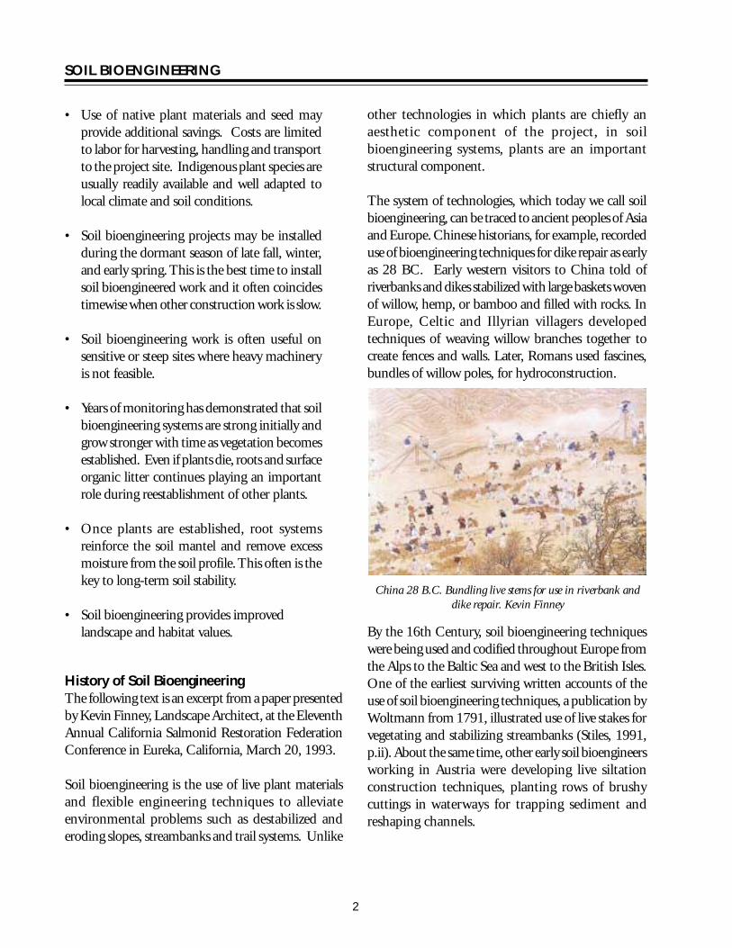
SOIL BIOENGINEERING
China Early 1900rsquos Bundling live stems for use in riverbank and dike repair Kevin Finney
Much of the development and documentation of soil bioengineering techniques since the Industrial Revolution has been done in the mountainous areas of Austria and southern Germany Extensive logging of the forests in the region resulted in increased environmental problems much like what we see in the United States today Such problems as extreme slope erosion frequent landslides and avalanches and severe streambank degradation required repair By the turn of the century European soil bioengineers had begun to find new applications for old folk technologies using them to develop methods to deal with the new environmental problems These early soil bioengineers mostly foresters and engineers by training began to study traditional techniques and to publish their work This compiled body of knowledge is where the soil bioengineering profession would develop in the following decades
Europe Early 1900rsquos Cutting and collection of live stems for soil bioengineering Kevin Finney
The biggest boost to development of new soil bioengineering techniques in Europe came as a result of political developments during the 1930rsquos Financial restrictions of pre-war years in Germany and Austria favored use of low cost local materials and traditional construction methods for public works projects Construction of the German Autobahn system during this time involved extensive applications of soil bioengineering technologies Use of indigenous materials and traditional methods was also consistent with spreading nationalist ideology In 1936 Hitler established a research institute in Munich charged
3
SOIL BIOENGINEERING
with developing soil bioengineering techniques for road construction (Stiles 1988 p59) Although this development work was lost a Livonian forester named Arthur von Kruedener the head of the institute continued to work in the field and is known in central Europe as the father of soil bioengineering
At the same time the Germans were establishing their research institute some of the most important early soil bioengineering work in the United States was being done in California Charles Kraebel working for the USDA Forest Service was developing his ldquocontour wattlingrdquo techniques for stabilizing road cuts Kraebel used a combination of bioengineering techniques including live stakes live fascines and vegetative transplants to stabilize degrading slopes in the National Forests of central and southern California His use of the term ldquowattlerdquo to describe his live fascine systems has stuck with us and continues to be used today Kraebelrsquos work was well documented in USDA Circular 380 published in 1936 Two years later the Soil Conservation Service now known as the Natural Resource Conservation Service (NRCS) began a study of bluff stabilization techniques along the shores of Lake Michigan That agencyrsquos work which included use of live fascines brush dams and live stakes was published in 1938 (Gray and Leiser 1982 p188)
USA 1930rsquos Installation of live fascines USDA
Publication
During the post-war period European soil bioengineers returned to studying developing and evaluating new techniques In 1950 a committee of soil bioengineers from Germany Austria and Switzerland was formed to standardize emerging technologies that became part of the German National System of Construction Specifications the DIN (Robbin B Sotir amp Associates Inc nd)
Arthur von Kruedenerrsquos book Ingenieurbiologie (Engineering biology) was published in 1951 and it was the mistranslation of the German title which gave us the English term we use today The use of the term bioengineering has caused some confusion and has proven problematic for researchers who find in this country the term most often refers to an area of medical research NRCS now refers to this work officially as ldquosoil bioengineeringrdquo a term which emphasizes the soil component of the system
German and Austrian soil bioengineers continued to perfect their techniques and to publish their work through the 1950rsquos and 60rsquos This was an important step in launching a more structural approach laying the foundation for development of the professional field of soil bioengineering In the United States two important projects were carried out in the 1970rsquos and 80rsquos These include Trials of Soil Bioengineering Techniques in the Lake Tahoe Basin designed by Leiser and others (1974) and Revegetation Work in Redwood National Park (Reed and Hektner 1981 Weaver et al 1987) Both of these studies have been well documented and provide important information about application of soil bioengineering techniques in the western United States
In 1980 Hugo Schiechtlrsquos Bioengineering for Land Reclamation and Conservation was published in Canada It presents for the first time in English the work of many important European soil bioengineers including Lorenz Hassenteufel Hoffman Courtorier and Schiechtl himself The book made technologies and history of their
4
SOIL BIOENGINEERING
development and applications accessible to the English speaking world In 1997 another Schiechtl book was published Ground Bioengineering Techniques for Slope Protection and Erosion Control To date his writings remain the most important work on soil bioengineering in the English language
Hugo Schiechtlrsquos Bioengineering for Land Reclamation and Conservation Kevin Finney
Subsequent publications including Gray and Leiserrsquos Biotechnical Slope Protection and Erosion Control and Sotir and Grayrsquos Soil Bioengineering for Upland Slope Protection and Erosion Reduction in the United States Gray and Sotirrsquos 1996 Biotechnical and Soil Bioengineering Slope Stabilization and the British Construction Industry Research and Information Associationrsquos Use of Vegetation in Civil Engineering have made bioengineering technologies better known in the engineering profession However there is still resistance to the techniques in many countries
Soil bioengineering approaches most often use locally available materials and a minimum of heavy equipment and can offer local people an inexpensive way to resolve local environmental problems The publicrsquos increased environmental consciousness often makes soil bioengineering solutions more acceptable than traditional ldquohardrdquo engineering approaches
Despite and maybe because of the differences in approach and philosophy between soil
bioengineering and other engineering methods of addressing environmental problems soil bioengineering technologies are especially appropriate today The scale and range of environmental problems require consideration of new technologies even when as illustrated earlier they are in fact centuries old
Basic Soil Bioengineering Concepts By knowing the climate and vegetation of an area it is possible to predict the nature of the soils There are however many exceptions resulting from differences in parent materials drainage slope and the time the soil has been exposed to these environmental conditions
Projects require more than site evaluation and measurement Design should consider the natural history and evolution as well as cultural and social uses of the surrounding landscape An awareness of these factors and how they shape present and potential future landscape is critical for project success Knowledge of current and future land management goals is also important A proposed soil bioengineering project within a forested landscape for example requires an understanding of the arearsquos geologic and glacial history itrsquos propensity for wild land fires wind storms and floods occurrence and trends of natural and management related erosion history of road construction methods and current maintenance practices sequence of vegetation removal and revegetation efforts and fire management history This information provides interesting lore and insight on the project arearsquos potential and capability
In addition to understanding landscape scale patterns it is important to observe trends within erosion sites Whether erosion occurs naturally or through human-induced activities a site begins to heal itself immediately upon ldquofailurerdquo In mountainous terrain for example wood may become embedded in the slope terracing eroding soils Once an angle of repose has been achieved
5
SOIL BIOENGINEERING
between these natural terraces vegetation begins to establish Herbaceous plants usually provide initial vegetative cover on these sites This initial cover also assists in establishment of soil microorganisms Typical succession patterns go from exposed ground through a herbaceous stage to pioneer shrub and tree and finally to a climax tree stage The primary goal is to examine and document these trends Soil bioengineering designs are intended to accelerate site recovery by mimicking or accelerating what is happening naturally
Site Evaluation and Design Checklist There are many soil bioengineering systems Selection of the appropriate technique or techniques is critical to successful restoration At a minimum consider the following
Climatic Conditions bull Precipitation types levels timing and
duration bull Temperatures including extremes
Topography and Aspect bull Slope gradient terrain shape elevation of
project area and direction of sun exposure Climates near the ground can vary considerably within short distances South facing valleys for example receive more direct sun rays causing higher soil temperatures increased evaporation more rapid snowmelt in the spring and generally drier conditions than on the more shaded north facing side This difference will influence erosion rates and the composition and vigor of vegetation
Soils bull Underlying substrate bull Root and water permeability moisture
holding capacity and nutrient availability bull Identify conditions above below or within
your project site which may have an affect on your project and incorporate these considerations into your design
Water bull If applicable stream and fish types affected
by the erosion site bull Location of natural drainage channels and
areas of overland flow from road surface bull Identify areas for safe water diversion bull Note condition of ditch line and culvert inlets
and outlets
Vegetation bull Plant types and amount growing within and
adjacent to the project site This is especially important to identify colonizing species
bull Locations for and preparation of future plant and seed collection
Erosion Process bull Type of mass wasting or surface erosion
features including seepage bull Source of eroding material road fill slope cut
slope landing etc bull Trend of sitendashimproving naturally remaining
uniform or worsening
Project Planning and Implementation Checklist Site Preparation bull Develop and implement a communication
plan to keep all involved interested and informed
bull Establish clear project objectives Have these objectives reviewedfuther developed and approved by participants including the local road manager
bull List all project phases Under each phase catalogue and schedule all work items For each work item list responsible party and the date their tasks must be completed Identify and resolve timing conflicts Build flexibility into the schedule
6
SOIL BIOENGINEERING
bull Sites often require earthwork prior to and during installation of a soil bioengineering system Timing conflicts can occur between scheduling heavy equipment hand labor work plant collection and use
bull Select the right equipment for the job
bull Identify and remove work hazards such as rocks boulders and tree stumps
bull Determine storage and staging areas and access routes for people and machinery to minimize site disturbance and improve efficiency
bull Ensure coordination between heavy equipment operator and handcrew
bull Temporarily divert excess water
bull Stockpile excavated soils for later use and retain or salvage existing vegetation for later use
bull Provide and maintain temporary surface erosion and sediment control measures
Project Work bull Before beginning the project conduct an
on-site field pre-work meeting At a minimum include those with vegetation and soils skills
bull Avoid earthwork in saturated soils Schedule heavy equipment work during periods of low precipitation
bull Collect plant materials during the dormant season Keep them protected from wind and heat Best results are obtained when installation occurs the same day materials are prepared however some believe greater success can be realized if stems are soaked in water five days prior to planting Further research shows that cut stems are still viable after being refrigerated several months prior to planting under the
proper temperature and humidity condition Although opinions differ on length of storage all agree proper storage and use are critical Protecting stems from wind and keeping them cool and moist are essential
bull Inspect project work daily ldquoYou get what you inspect not what you expectrdquo
Plant Materials Living vegetation is the most critical component of a soil bioengineered system Existing vegetation and knowledge of predisturbance and surrounding area plant communities can inform the designer of project limitations opportunities and long term ecological goals Work with local plant experts such as botanists and silviculturalists to select the most appropriate plant species for your project
Which plants to use are affected by the following factors
bull Site characteristics (topography elevation aspect soil moisture and nutrient levels)
bull Existing vegetation bull Intended role of vegetation in the project
such as rooting characteristics bull Growth characteristics and ecological relationships of the plants bull Availability bull Logistical and economic constraints
Plants which can resist mechanical stresses of erosion floods and landslideswhile developinga strongstabilizing root system are best suited for soil bioengineering applications Examples of riparian plants suitable for soil bioengineering work include but are not limited to willows dogwoodscottonwoods big leafmaples spruce cedars aspen and alders
Plants better suited for dryer and poorer soil conditions include bitter brush snowberrywhite pine lodgepole pine vine maple Douglas maple oceanspray red elderberry and salmonberry The best indicator of what plant materials one should consider
7
SOIL BIOENGINEERING
for a soil bioengineering project are the plants growing on or adjacent to the project site Work with local vegetation specialists to understand the limitations and opportunities encountered when stabilizing an erosion site
Most commonlyplant materials are chosen from among those available on the site or nearby Alternatively the soil bioengineer may find an area where the vegetation will be removed or salvaged for future development Logistical concerns are also important in the selection of plant material
A single species may serve the primary structural requirement of the vegetation in a soil bioengineered system However it is preferable to use a mixture of species with varying but complimentary characteristics Benefits of using multiple species include
bull Less susceptible to devastation by disease or pests
bull Offers combinations of deep and shallow rooting species and high and low elevation vegetation
bull Allows the system to respond to changes in site conditions
bull Offers greater diversity and habitat values
Plant Movement Guidelines The reason for setting plant movement guidelines is to increase likelihood of plants surviving growing to maturity and reproducing Chance of success is much greater if locally collected materials are used
Upland plant species Use local seed (collection) zones to identify where best to collect seed cuttings or plants A seed zone is an area having a defined boundary and altitudinal limits within which landform and climate are sufficiently uniform A silviculturalist or botanist will direct you to this source of information Map 1 provides an example of a seed zone map in Washington State
Based on climatic and physiographic information seed zones were developed in 1966 to reduce risk of maladaptating commercial tree species and to provide structure for commercial seed trade Each zone has geographic boundaries and is additionally divided into 500-foot elevation intervals Seed lots are coded by both seed zone and elevation band
When collecting seeds cuttings or plants for smaller projects (perhaps a one-time collection) the elevation band can extend approximately 250 feet above and below the site
Shrubs forbs grasses and riparian species Use watershed boundaries as seed cuttings and plant collection and transplant zones with500-foot elevation intervals Planting seeds cuttings or plants outside the seed zone or watershed should be done only after consultation with a silviculturist or botanist
Gene Pool Conservation Guidelines Just as important as plant movement guidelines are making sure the seed lots cuttings or plant lots are genetically diverse To prevent loss of genes in the population use a minimum of 30 to 50 unrelated donor plants Collecting equal number of seeds cuttings or plants from each donor plant or area will also ensure representation by as many parent plants as possible
Donor plants should also be separated by sufficient distance to reduce risk of relatedness ie originating from the same rhizome or root system or for outcrossing plants having one or both parents in common
8
SOIL BIOENGINEERING
TECHNIQUES FOR PROJECT IMPLEMENTATION
Native Plant Cuttings and Seed Collection Advantage Inexpensive Use of local stock Better adapted to local climate and soil conditions
Disadvantages Can have high mortality if collection and storage not performed correctly Can be expensive
Tools needed Hand pruners hand clippers untreated twine burlap sacks (moistened and lined with wet leaves or mulch) plastic sheeting
For seed collection Paper bags cool dry storage area
Procedure bull Collect from 30 to 50 parent plants in good
condition Never take more than 50 percent of seed or cuttings from a given area
bull Collect an equal number of seeds or cuttings from each plant
bull Use watersheds (and 500 foot elevation intervals) for collection of seeds or cuttings of shrubs forbs grasses and ripariantree speciesThe elevation band can be considered to extend approximately 250 feet above or below the site
bull For plant cuttings use young shoots (1 to 2 years old) Older and larger stems tend to have higher mortality Refer to Plant Materials section for information on preferred plant species
bull Protect cuttings fromwind bycovering with plastic sheeting Protecting stems from wind and keeping them cool and moist are essential
bull Seeds collected should be ripe or mature
Harvesting with loppers Robbin Sotir amp Associates
Harvesting with brushsaw Robbin Sotir amp Associates
Harvesting with chainsaw Robbin Sotir amp Associates
9
SOIL BIOENGINEERING
Note A seed zone is an area having a defined boundary and altitudinal limits within which landform and climate are sufficiently uniform Refer to map 1
Map 1ndashSeed zones
10
SOIL BIOENGINEERING
Salvaging plants USDA Forest Service
Salvaging and Transplanting Native Plants Advantage Inexpensive
Disadvantages Can have high mortality if salvaging and transplanting not performed correctly and timely Soil moisture deficiency and over exposure to air and heat are critical factors in plant mortality
For trees shrubs forbs and riparian species use watershed boundaries as collection zones with 500 foot elevation intervals The elevation band can extend approximately 250 feet above or below the site
Plants should be dormant during salvaging and transplanting
Tools needed A flat-bladed spade metal file (for sharpening the spade) hand clippers (for pruning) burlap sacks (moistened and lined with leaves or mulch) plastic sheeting
Procedure Salvaging bull Locate a small and healthy plant growing by itself
Trees and shrubs growing in clumps connected by underground runners are less likely to survive transplanting
bull Clear area around plant of leaves and twigs Shrubs can be pruned if they have a few long branches (over 4 feet) Have a moist burlap sack nearby lined with wet leaves or mulch
bull Dig in a circle approximately eight inches from the main stem A larger excavated area of one foot may be required if it is a large shrub or seedling (3 to 4 feet high) Gently work the spade under the plantrsquos roots and lift the root ball out on the shovel blade Immediately place the root ball into the moistened burlap sack If you are unable to remove entire root ball collect as much of the root system as possible It is especially critical to protect fine root hairs of the plant It is also important to protect excavated plants from direct air and heat exposure
Transplanting bull Salvaged plants should be planted within two hours
of lifting Keep plants moist and free from air and heat exposure
bull Holes should be dug overly large Recommendation is to dig two times the volume of root ball Larger holes will be required in ldquotighterrdquo soils If available add a small amount of low dose time-release fertilizer and mix into the soil Note For bareroot and container plants do not add fertilizer the first year Planting holes must be deep enough so the downslope side of the rootball is entirely buried
bull Roots should be carefully spread out so none are kinked or circling Protect roots especially fine root hairs on the main root system Add water if availablewhen the plant is half installed to reduce voids and increase root and soil contact If possible water when planting is completed
11
SOIL BIOENGINEERING
Planting vegetation USDA Forest Service
bull On-site soil should be used to backfill the hole Firmly tamp the soil around the plant Be careful not to over compact the soil Once transplanted prune the plant to conserve ldquofuelrdquo for root development Prune to balance tops with roots For example if you cut off roots cut back tops by about12 Use clippings as mulch around the plant
bull Transplanting a microsite Depending on site conditions and project objective it may be preferred to salvage and transplant a small section of ground This ground section usually contains several plants with roots seed soil soil microorganisms and duff materials This technique provides great benefits to the area trying to revegetate For transplanting small sections of ground excavate an area large enough to ldquoplantrdquo the entire piece Lay it in the excavated area and level with adjoining ground Use excavated soil to secure edges of transplanted piece Tap gently in place Whenever possible water the transplant
Planting Containerized and Bare Root Plants Advantages Best application for long term increase in mechanical strength of soils Can be quickly applied to slopes materials are inexpensive creates a rooting zone over time to protect soils from erosion
Disadvantages Can have high mortality if planting not performed correctly Soil moisture deficiency and over exposure to air and heat are critical factors in plant mortality
Containerized and bare root plants must be installed with careful attention to protect their root systems
Tools needed Hoedad or dibble tree planting bag water for root dipping of bare root plants
Procedure bull The planting hole should be dug deep and wide
enough to fully accommodate the natural configuration of the root system
bull The roots should be carefully spread out so none are kinked circling or jammed in the bottom of the planting hole
bull On-site soil should be used to backfill the hole and the plant firmly tamped but not overly compacted into the ground Add water if available to reduce voids that can desiccate roots
12
SOIL BIOENGINEERING
Distribution of seed and fertilizer USDA Forest
Distribution of Seed Fertilizer and Certified Noxious Weed-free Straw or Hay Advantages Can be quickly applied to slopes materials are inexpensive creates shallow fibrous rooting zone in the upper foot or so of the surface profile which binds near-surface soils and protects soil surfaces from surface water runoff wind and freeze-thaw erosive forces
Disadvantages Not adequate alone for mitigating highly eroded surface erosion areas or for landslide stabilization
Seeding should be applied in combination with planting trees and shrubs to provide root reinforceshyment of surface soils Best times to apply include spring and early autumn If project is implemented in autumn it is critical to allow adequate time for good root and leaf development (approximately 4 inches) prior to winter Refer to Natural Resource Conservation Service technical guide for seeding dates available in every US county
Spreading straw mulch USDA Forest Service
Seeding involves application of grass forb and woody plant seed mixes to erosion areas
Tools needed McLeod rake hand seeder protective respiratory mask
Procedure bull Round top edge of slope failure (fig 18) For
project success it is critical to address this ldquoinitiation pointrdquo or chronic source of the erosion A common initiation point for these failures is located at the upper boundary of the site For project success it is critical to remove or round off slope overhang (figure18)
bull Smooth all eroding areas such as rills or gullies In addition prepare a seed bed by slightly roughening area Do this by raking across slope face never downslope Raking downslope can create depressions for channeling water
Slope terracing USDA Forest Service
13
SOIL BIOENGINEERING
bull Create terraces on contour when slopes exceed 35 percent Dig these terraces 10 to 14 inches deep across slope face Spacing usually varies from 4 to 10 feet depending on conditions (fig 2) The objective is to accelerate establishment of plants by reducing slope angle and steepness between each terrace
bull Broadcast seed fertilizer and weed-free straw Make sure your seed is covered with at least 14 inch of soil Seed and fertilize as required by mix directions For example a mix may consist of 1 part seed (annual rye and forb mix) and 3 parts fertilizer (161616) Organic amendments in place of fertilizers also work well Work with local vegetation and soils specialists to determine desirable seed species and soil nutrient needs In addition determine if burying seed is critical for germination
bull Hand spreading of mulch is sufficient However machine application spreads materials more evenly and requires less mulch for full coverage As a result machine application may be more economical than hand distribution
bull In addition to mulching the site it is critical to protect areas from additional surface water flow specifically overland flow from roads Direct water flow away from the project area by constructing crossdrains across the road surface several feet prior to the project area Location and number of crossdrains needed will depend on several factors including road gradient and whether or not the road is outsloped or insloped above project area Crossdrains are cut approximately 6 inches deep across road surface to a vegetated stable point on the fillslope These hand-excavated drains are a temporary measure until heavy equipment is available to dig deeper water diversions An alternative to crossdrains or an additional measure to consider is to install drain rock and allow the water to move through the project area
Live staking Robbin Sotir amp Associates Live Staking Advantages Overtime a living root mat developes soil by reinforcing and binding soil particles together and by extracting excess soil moisture Appropriate technique for repair of small earth slips and slumps that usually have moist soils
Disadvantages Does not solve existing erosion problems (excluding benefits from associated mulch) live staking is not a short-term solution to slope instabilities
Tools needed Hand pruners and clippers untreated twine deadblow or rubber hammer burlap sacks (moistened and lined with wet leaves or mulch)
Procedure Vegetative cuttings are living materials and must be handled properly to avoid excess stress such as drying or exposure to heat They must be installed in moist soil and adequately covered with mulch Soil must be tamped to eliminate or minimize air pockets around buried stems
Installation is best accomplished in late fall at onset of plant dormancy in the winter as long as the ground is not frozen or in early spring before budding growth begins
Live staking involves insertion and tapping of live rootable vegetative cuttings (eg willow cottonwood
14
SOIL BIOENGINEERING
and red-osier dogwood) into the ground If correctly prepared and placed the live stake will root and grow
bull Live cuttings are usually 12 to 1 12 inches in diameter and 18 to 36 inches long Materials must have side branches cleanly removed and bark intact Young shoots 1 to 2 years of age work best Older and larger stems have a higher rate of mortality but can be successful with additional treatment eg bark scoring and rooting hormones
bull Cut basal end at an angle for easy insertion into the soil Cut top square (figure 1)
bull Best results are obtained when installation occurs the same day stakes are prepared however some believe greater success can be realized if stems are soaked in water 5 days prior to planting Further research shows that cut stems are still viable after being refrigerated several months prior to planting Although opinions differ on length of storage all agree proper storage and use are critical Protecting stems from wind and keeping them cool and moist are essential
bull Orient buds up
bull Tap live stake into the ground at right angles to the slope Installation may be started at any point on the slope face
bull Two-thirds to three-quarters of the length of the live stake should be installed into the ground and soil firmly packed around it after installation (figure 1) The more stem exposed to air the more moisture is lost This moisture is critical for root development
bull Install live stakes 2 to 3 feet apart using triangular spacing Density of installation should range from 2 to 4 live stakes per square yard
bull Be careful not to split stakes while tamping them into the ground Covering the stake with a 2 by 4-inch wood section will cushion the blows thus protecting the stake from splitting Trim damaged top area
bull Rebar can be used to make a pilot hole in firm soil Tamp the live stake into the ground with a deadblow (hammer filled with shot or sand) or rubber mallet
Figure 1ndashLive stake
14 to 13 ldquo Flat top
12 to 1-12 ldquo
18 to 36 ldquo
Angle
Bury 23 to
34 of stem
not to scale
15
SOIL BIOENGINEERING
Hand excavated terraces for erosion control blanket USDA Rolling out erosion control blanket USDA Forest Service Forest Service
Installation of Erosion Control Blanket Advantages Excellent for mitigating surface erosion The blanket offers immediate and uniform slope protection from rain and overland water flow if it is installed in full contact with the soil surface
Disadvantages Can be labor intensive and expensive Requires numerous wood stakes or livestems Too much grass within the blanket will lead to over competition for moisture sunlight and nutrients and may result in high tree and shrub mortality
Installation of erosion control blankets involves site preparation trenching application of grass andor forb seed mix and fertilizer and installation of fabric This technique is suitable for treating surface erosion areas especially fillslopes where there is a concentration of surface water runoff (figure 3)
Tools needed McLeod rake hand seeder 6-inch spikes and 2-inch pieces of rubber or fire hose hand prunners and clippers heavy duty scissors deadblow or rubber hammer
Procedure bull Round top edge of slope failure (figure 18) For
project success it is critical to address initiation point or chronic erosion source of the slope failure The common initiation point for these
failures is located at the upper boundary of the site For project success it is critical to remove and or round off slope overhang (figure 18)
bull Smooth all eroding areas such as rills or gullies In addition roughen entire site Do this by raking across and not downslope Raking downslope can lead to channeling water
bull Create a small berm on road edge (figure 2)
bull Excavate terraces 10 to 14 inches deep and 5 feet apart (figure 2)
bull Broadcast seed and fertilizer on treatment area as required by mix directions An example one seed mix may include 1 part annual rye and 3 parts 161616 fertilizer Organic amendments can be used in place of inorganic fertilizers
bull Roll out blanket parallel with road between trenches Fabric edges should lay evenly across bottom and top trenches Begin matting installation at bottom two trenches (figure 2)
bull Follow these directions for remaining rows The upper row of fabric should overlap the lower row Lay edge of top row of fabric into shallow terrace created while excavating the berm at road edge (figure 2)
16
SOIL BIOENGINEERING
bull To secure fabric into road edge nail 60D spikes through a hose piece washer If road surface is not too compacted use dead wood stakes instead of nails Nail or stake every 3 to 4 feet across top row of fabric at road edge (figure 2) Once nailed rake bermed soil back over matting edge Note Check with road manager to ensure maintenance activities will not require blading road edge at fabric site Road blading would lead to tearing out sections of the project If this is a major concern install upper edge of fabric a few 4 to 6 inches below the road edge
bull To secure fabric to slope face install live stakes into fabric across slope and through terraces
Optimum spacing of these stakes ranges from 2 to 3 feet Maximum spacing between stakes should not exceed 4 feet (figure 3)
bull Tamp live stakes in leaving 14 to13 of stem above ground and 34 to 23 below ground (figure 1) Trim stakes if more than 13 is exposed Average length of stake ranges from 18 to 36 inches Stakes should be flatcutontopand diagonalcuton bottom so they will be installed correctly and easily (figure 1) Remove top sections of stakes damaged during installation If you are not working in moist soil eg riparian area the willows will not survive In these cases it would be more cost effective to use wood stakes instead
CutslopeShallow terrace
6rdquo berm
Cutslope
Nail and washer 3rsquo to 4rsquo apart
Roadbed
Overlap matting on terraces
Terrace 10rdquo to 14rdquo deep
5rsquo ft
Matting
5rsquo ft
Roadbed
not to scale
Figure 2ndashInstallation of erosion control blanket
17
SOIL BIOENGINEERING
Roadbed Terraces
Side view
Terrace
Nails or stakes Roadbed
Nails or stakes
Terrace
not to scale
Live cribwall one month after construction USDA Forest Service
Figure 3ndashInstallation of erosion control mat
Construction of Live Cribwalls Advantages Appropriate at base of a cut or fillslope where a low wall or log may be required to stabilize toe of the slope and reduce slope steepness Useful where space is limited and a more vertical structure is required Provides immediate protection from erosion while established vegetation provides long term stability Aesthetically more pleasing and possibly less expensive compared to conventional gabion baskets
Disadvantages Not designed for or intended to resist large lateral earth stresses Depending on soil quality of cutslope may have to use commercial fill material Can be labor intensive and expensive to construct Can have high mortality if willow stems are not collected when dormant not cut and used the same day or mishandled in transfer
A live cribwall consists of a hollow box-like interlocking arrangement of untreated log or timber members The structure is filled with suitable backfill material and
18
SOIL BIOENGINEERING
Live cribwall during construction USDA Forest Service
layers of live branch cuttings such as willow or dogwood which root inside the crib structure and extend into the slope Cribwall should be tilted or battered back if constructed on a smooth evenly sloped surfaceOnce live cuttings root and become established subsequent vegetation gradually takes over the structural functions of wood members (figure 8) Coordinate with road manager prior to construction Often their primaryconcern is the structure will block water flow in the ditch line Make sure the design takes this concern into consideration
Basic design ideas are from Sotir and Gray 1982 and 1992 The following description and guide however includes several changes
Tools needed Chainsaw McLeod rake deadblow or rubber hammer 8 to 12 inch spikes or rebar shovels hand prunners and clippers
Procedure A Starting at lowest point of the slope excavate
loose material until a stable foundation is reached
B Place first course of 4 to 8 inch diameter logs or timbers at front and back of excavated foundation approximately 4 to 5 feet apart and parallel to the slope contour These are your main beams (figure 4)
C Lay 4 to 5 foot long and 4 to 8 inch diameter cross beams (either conifer or hardwood) across
main beams Spike or wire cross beams to main beams front and back (figure 5)
D Fill inside of main frame with soil Note Some gravel and rock can be used however willows will have more vigor if soil conditions are favorable If consequence of project failure is high it is critical to use commercial fill material
E Lay 5 foot long and 12 to 3 inch diameter trimmed live cut branches (3 to 6 inches apart depending on soil moisture) between cross beams and into cutbank On the bottom layer lay the basal ends of live cut branches under back main beam and on top of front main beam (figure 5 and figure 6) Note The purpose is to take full advantage of excess water at slope base If you do not have excess soil moisture conditions you do not have to lay butt ends of branches under back main beam Instead you can lay them directly over this beam
F Following ldquoArdquo and ldquoBrdquo start second layerThe onlydifference is set main beams back the width of bottom main beams and into cutbankThis allows cribwall to lean into cutbank and keeps fill material from falling out of front of cribwall (figure 7)
G Fill frame with soil
H Lay 4 to 5 foot long live cut branches on top of front and back main beams and between cross beams Lay these live branches approximately 3 inches apart (figure 5) Spacing of branches depends on availability of moisture and can range from side-by-side to 6 inches apart
I Continue constructing layers following ldquoErdquoldquoFrdquo and ldquoGrdquo until you reach specified height
J If needed construct wings or flanges to catch soil at structurersquos edges and to key in the structure to the slope face
19
main
ain b
SOIL BIOENGINEERING
K Cribwall should be tilted back if constructed on a smooth evenly sloped surface This can be accomplished by excavating the back of the stable foundation (closest to the slope) slightly deeper than the front to add stability to the structure (figure 8)
L May be constructed in a stair-stepped fashion with each successive layer of timbers set back 6 to 9 inches toward back cut slope face from previously installed course
Half Cribwall bull To insure minimum road width of 14 feet it
may be necessary to construct a half cribwall This is done by cutting cross beams width in half from 4 to 2 feet wide at base of cribwall (figure 7) and gradually increasing cribwall width by layer as desired cribwall height is being achieved (figure 7 and figure 8)
Toe Log Technique bull The toe log technique is a handy tool for very
small cutslope erosion features eg 10 feet high by 15 feet wide Place a 20 to 24 inch diameter log along the base of the erosion site Lay 5 foot long and 12 to 1 inch diameter live cut branches (side-by-side to 6 inches apart depending on soil moisture) on top of the log and into cutbank (figure 7) The purpose is to take full advantage of excess water at slope base Place soil behind the log with soils from the slope face Toe logging is a quick and effective tool in stabilizing base of slopes However it is only effective when sites are small and only slightly over steepened It is very important to use the right size log for existing slope condition
When constructing a live cribwall half cribwall or toe log the initiation point of the slope failure must be addressed The common initiation point or source of chronic erosion for these failures is located at the upper boundary of the site For project success it is critical to remove or round off slope overhang (figure 18)
Rear beam
Front m eam
Cutslope
Edge of cutbank
Road
For half cribwall
Ditch
20
not to scale
4-8 diameter
Figure 4ndashLive cribwall construction
20
SOIL BIOENGINEERING
Rear main beam
Front main beam
Cutslope
Edge of cutbank
Road
3 apart
Ditch
not to scale
4 to 8
20
5 long
8 to 12spike
12 to 3 diameter 5 in length
4-8 diameter
Figure 5ndashLive cribwall construction
Crossbeam
Back mainbeam
Spikes Ditch
Roadbed
Cutslope
Willow on top of front main beam
Willow under rear main beam
Existing roadbed
not to scale
Figure 6ndashLive cribwall construction
21
SOIL BIOENGINEERING
3rsquo to 5rsquo
Constructed into slope
minimum of 6rsquo 8 to 12rdquo
Ditch
Roadbed
Half cribwall
1-12 to 3rdquo 4rsquo diameter
Ditch
Roadbed Ditched
Toe log 20-24rdquo diameter 2rsquo
Figure 7ndashLive cribwall-stepped full half and toelog construction
Evacuated cutslope
New slope
Roots
5rsquo to 6rsquo
Soil
Ditch Roots
Figure 8ndashLive cribwall battered construction
22
SOIL BIOENGINEERING
Live facines illustration Kraebel Live Fascine Advantages Immediately reduces surface erosion or rilling Suited to steep rocky slopes where digging is difficult Capable of trapping and holding soil on the slope face thus reducing a long slope into a series of shorter steps Can also be used to manage mild gully erosion and can serve as slope drains when bundles are angled Best suited for moist soil conditions Note Where soil moisture is not sufficient for supporting live materials fascines can also be constructed of plant stems not intended for rooting The bundle still traps and holds sediments and reduces slope length and steepness between terraces Plant vegetation on andor between the terraces As inall projects living recovery is dependent on successfully establishing the vegetation
Disadvantages On steep or long slope lengths high runoff velocities can undermine live fascines near drainage channels Significant quantity of plant material is required and can dry out if not properly installed Best suited for riparian moist soil conditions Otherwise high plant mortality could occur
Live fascines (Kraebel1936 and Sotir and Gray1982 and 1996) also referred to as contour or willow wattling are long bundles of branch cuttings bound together into sausage like structures (figure 9)
Tools needed Hand pruners and clippers untreated twine (not hemp) pulaski or hazel hoe deadblow or rubber mallet McLeod rake dead plant materials
Procedure bull Excavate 10 to 14 inch deep terraces along slope
contour and the full width of treatment area Spacing of terraces averages between 5 to 7 feet with a goal of 11 slope Terrace placement is a function of slope and should be calculated Terrace excavation and live fascine installation should progress from base of project up to slope crest
bull Bundle willow branches Other species such as red-osier dogwood or snowberry can be used For best results cut and use plant materials same day (See comments in Live Staking about collection and timing of installation) Butt ends and top ends are usually laid alternately until a bundle has been created which looks like an 8 to10 inch wide sausage Plant materials should be about 12 to 5 inches in diameter and about 4 to 8 feet in length (figure 9) Bundles are then tied together using up to 20 percent dead material and bound with untreated lengths of twine Note Use of up to 20 percent dead materials retains structural properties of live fascine and bundle still has enough live material to grow
bull Lay bundle across terrace splice together ends of each (figure 9) and do not overlap Bundles should be 14 to 13 exposed
Live facine installation USDA Forest Service
23
SOIL BIOENGINEERING
Live facine installationndashangled Robbin Sotir amp Associates
bull Next live stake the downslope side of terraces at middle and overlap points to hold live fascines in the terrace Be sure to splice ends of bundles In addition place wood stakes through live facines every two feet Wood stakes should be driven directly through bundle center (figure 9) Live willow and wood stakes should be 1 to 3 inches in diameter and 2 to 3 feet long Stakes should be flat cut on top and diagonally cut on bottom to ensure appropriate and easy installation Remove top section of live stakes damaged during installation
bull Stand in completed terrace and begin excavation of second terrace This process will allow soil from second terrace to cover first row Walk on wattles to compact and to gain good soil fascine contact
bull If available water fascine to work soil into the bundle for increased soil contact and decreased desiccation
bull Move upslope to next terrace alignment and repeat process (figure 9)
1
2
3
Untreated Twine Ties
Stems 12 to 1-12 diameter 8 to 10 diameter
4 to 8 length not to scale
Live facine Wood stake
Live stake
Spacing averages 5rsquo to 7rsquo
face measurement
Figure 9ndashLive fascines
24
SOIL BIOENGINEERING
Brushlayering Advantages Breaks up slope length into a series of shorter slopes separated by rows of brushlayer Reinforces soil as roots develop adding resistance to sliding or shear displacement Reinforces soil with unrooted branch stems Provides slope stability and allows vegetative cover to become established Traps debris on slope Aids infiltration on dry sites Dries excessively wet sites
Disadvantages Recommended on slopes up to 21 in steepness and not to exceed 15 feet in vertical height Labor intensive
Brushlayering (Sotir and Gray 1982 and 1992) consists of placing live branch cuttings in small terraces excavated into the slopeTerraces can range from 2 to 3 feet wide This technique is similar to live fascine systems because both involve cutting and placement of live branch cuttings on slopes The two techniques differ in the orientation of the branches and depth they are placed in the slope In brushlayering cuttings are oriented perpendicular to slope contour (figure 10) This placement is more effective fromthe pointof view of earth reinforcement and mass shallow stability of the slope
Tools needed Hand pruners and clippers untreated twine (not hemp) pulaski or hazel hoe shovel deadblow or rubber hammer McLeod rake
Digging terraces for brushlayer installation Robbin Sotir amp Associates Brushlayer installation Robbin Sotir amp Associates
Procedure bull Begin project at base of treatment area Excavate
terrace so that approximately 14 of average brush length extends beyond slope face Do not over excavate This technique can trigger soil movements during installation It is important therefore to perform installation in phases and to avoid excavating more area than is necessary to install plant materials (figure 10)
bull Lay an appropriate amount (ie 20 to 25 stems per yard) of single or multiple mix of live brush species along trench sidewall Length of stems can vary from 3 to 4 feet and diameter 12 to 3 inches (figure 10)
bull Stand in completed terrace and begin excavation of second terrace This process allows soil from second terrace above to cover first brushlayer row Compact and slightly mound soil behind brushlayers
bull Move upslope to next trench alignment and repeat process (figure 10)
Brushlayers modified with log terracing installing a short small log (figure 10) can modify brushlayers The log provides additional support to the brushlayer reduces slope angle and serves as a small terrace to ldquocatchrdquo rolling rocks rather than allowing them to roll down the slope and damage vegetation
25
Slope
Installation fall line
direction
SOIL BIOENGINEERING
Brushlayering just after installation Robbin Brushlayering 3 months after installation Sotir amp Associates Robbin Sotir amp Associates
Spacing averages 5-7
Stems 1 14 to 2
diameter
2
3
Spacing 4 to 10
Plant shrubs and trees throughout slope face
To reduce slope angle Live branch cuttings
Log (4 to 6 diameter)
Brushlayer
Length = 2 to 6
Stake
Brushlayer with log terrace
not to scale
Figure 10ndashBrushlayering and brushlayering w log terrace
26
SOIL BIOENGINEERING
Willow fencing with brushlayering USDA Forest Service
Willow Fencing Modified with Brushlayering Advantages These structures reduce slope angle providing a stable platform for vegetation to establish Willow fences trap rolling rocks and sliding debris and protects vegetation growing lower on the slope Willow fences provide support for small shallow translational or rotational failures Sites where fine textured soils can provide ample summer moisture or where seepage of groundwater provides moisture are suitable for willowbrushlayering fence installations These structures can also be constructed on dryer sites however expect high willow mortality In these situations the willow shelf is considered a temporary planting platform It is important therefore to establish deeper rooting shrubs and trees within the shelf When the structure begins to decay root systems of other plants will serve as the permanent feature
Disadvantages Significant quantity of plant material is required Moist site conditions are required for the fence to sprout and grow
Willow fencing with brushlayering is essentially a willow fence supported on a short brushlayer Specifically it is a short retaining wall built of living cuttings with a brushlayer base (figure 11) Willow fencing can also be used without base brushlayering (Polster 1998)
Tools needed Hand pruners and clippers pulaski or hazel hoe McLeod rake deadblow or rubber hammer wood stakes or rebar
Procedure Brushlayering bull Begin project at base of treatment area Excavate
16 to 20 inch deep trenches along slope contour and for full width of treatment area Spacing of trenches averages between 5 to 8 feet full measurement depending on site conditions This technique can cause additional erosion during installation therefore it is important to construct project in phases and to avoid excavating more area than is necessary to install plant materials (figure 11)
12 to 2 diameter
Willow fencing
18 to 36 long stakes 2 to 3 diameter
Brushlayer
18 to 36 long cuttings 1 2 to 2 diameter
Figure 11ndashWillow fencing modified with brushlayering
27
SOIL BIOENGINEERING
bull Lay live brush stems along base of trench Length of stems average 16 inches in length and diameter of 12 to 2 inches Approximately 14 of average brush length should extend beyond slope face (figure 10)
Willow fencing bull Install supporting 18 to 36 inch long wood
stakes cuttings or rebar Average diameter of stakes ranges from 2 to 3 inches
bull Place a few shrub cuttings 18 to 36 inch long and 12 to 2-inch diameter cuttings behind these supports
bull Place enough soil behind these supports to hold the shrub cuttings in place
bull Stand in the trench and begin excavation of second row This process will allow soil from second trench to cover first willow fencing brushlayer row
bull Compact and slightly mound soil on brushlayer and behind willow fence
bull As more soil is added add additional cuttings until the final height of the fence is achieved A goal should be to construct a 21 slope or less between the top of the willow fence and the bottom of the one above
bull Move upslope to next trench alignment and repeat process (figure 11)
Branchpacking just after installation Robbin Sotir amp Associates
Branchpacking Advantages As plant tops grow branchpacking system becomes increasingly effective in retarding runoff and reducing surface erosion Trapped sediment refills localized slumps orholeswhile roots spreadthroughout the backfill and surrounding earth to form a unified mass (figure 12)
Disadvantage Not effective in slump areas greater than 4 feet deep or 5 feet wide
Branchpacking (Sotir and Gray 1992) consists of alternating layers of livebranch cuttings and compacted backfill to repair small localized slumps and holes (figure 12)
Tools needed Hand pruners and clippers deadblow or rubber hammer untreated twine McLeod rake shovel wood stakes
Branchpacking just after installation Robbin Sotir amp Associates
28
SOIL BIOENGINEERING
Branchpacking post installation Robbin Sotir amp Associates
Procedure bull Starting at lowest point drive wooden stakes
vertically 3 to 4 feet into the ground Set them 1- to 1 12 -feet apart Wooden stakes should be 5 to 8 feet long and made from 3-to-4 inch diameter poles or 2 by 4 lumber depending upon depth of particular slump or hole
bull Place a layer of live cut branches 4 to 6 inches thick in bottom of hole between vertical stakes and perpendicular to the slope face (figure 12) Crisscross branches with growing tips generally oriented toward slope face Some basal ends of branches should touch the back of the slope
bull Install subsequent layers with basal ends lower than the growing tips of the branches This is to insure developing root systems will be located at water collection points on the slope
bull Each layer of branches must be followed by a layer of compacted soil to ensure soil contact with branch cuttings
bull Final installation should match existing slope Branches should protrude only slightly from the filled face
bull The soil should be moist or moistened to insure live branches do not dry out
1 to 1-12
Live branch cuttings 14 to 2 diameter
Compact fill material
Wooden stakes 5 to 8 long 2 x 4 lumber driven 3 to 4 into undisturbed soil
4 to 6 inch layer of live branch cuttings laid criss cross and
touching back of hole
Live branch cuttings should protrude slightly from
backfill area
Several weeks or months later
spacing not to scale
Figure 12ndashBranchpacking
29
SOIL BIOENGINEERING
3 to 4 inch layer of live branch cuttings laid in crisscross and touching undisturbed soil on gully bed
Several weeks later
Live branch cuttings 1 to 2 in diameter
Compacted fill material 6 to 8 layer
Gully bed
Figure 13ndashLive gully repair
Live Gully Repair Advantages Offers immediate reinforcement to compacted soil reduces velocity of concentrated flow of water and provides a filter barrier to reduce rill and gully erosion
Disadvantages Limited to rills and gullies which are a maximum of 2-feet wide 1-foot deep and 15- feet long
Live gully repair (Sotir and Gray 1992) utilizes alternating layers of live branch cuttings and compacted soil to repair small rills and gullies Similar to branchpacking this method is more appropriate for repair of rills and gullies
Tools needed Hand pruners and clippers shovel McLeod rake untreated twine
Procedure bull Starting at lowest point of the slope place a 3shy
to 4-inch thick layer of live cut branches at lowest end of the rill or gully and perpendicular to the slope (figure 13)
bull Cover with 6-to 8-inch layer of soil
bull Install live cut branches in a crisscross fashion Orient growing tips toward slope face with basal ends lower than growing tips
bull Follow each layer of branches with a layer of compacted soil to ensure soil contact with live branch cuttings
30
SOIL BIOENGINEERING
Figure 14ndashVegetated geotextile
Vegetated Geotextile Advantages Retards rill and gully erosion stabilizes fill banks Is less expensive than other retaining walls such as gabion or Hilfiker baskets
Disadvantage Can be expensive if heavy equipment required
Synthetic or organic geotextile wrapped around lifts of soil with a mix of live branches placed between layers There are numerous opportunites of blending geotechnical-engineered systems with soil bioengineering The following is one example
Tools needed Backhoe geotextile hand pruners and clippers McLeod rake shovel untreated twine
Procedure bull Excavate lower edge of slope break and bench
backcut Compact the soil layer Note Structural integrity is dependent on compacted soil layers Even with mechanized firming soils support live cuttings
bull Lay first layer of geotextile down into the bench
bull Fill lowest lift with gravel fold back and stake securely
bull Fill subsequent layers with soil and layers of live cut branches (figure 10) and alternate with lifts (figure 14) Each layer must be compacted
bull The structure can be built with a vertical face or stair-stepped and sloped back into the hillside
31
SOIL BIOENGINEERING
Installation - cutslope stabilzation with log terracing USDA Forest Service
Log Terracing Advantages Logs create terraces reducing length and steepness of slope provides stable areas for establishment of other vegetation such as trees and shrubs
Disadvantages Labor intensive and with potential safety hazards
Tools needed Chainsaw PV pole blocks and cable power winch shackles and chokers pulaski Mcleod and shovel wood stakes hand pruner and clippers traffic control signs
Procedure bull The technique utilizes alternating terraced logs
to stop surface erosion on eroding slopes Stopping the erosion is critical for successful revegetation efforts Specifically log terracing shortens slope length and gradient between each structure providing stable planting areas throughout most of the slope face (figure 15)
bull Prior to beginning a log terracing project place traffic control signs several hundred feet on both sides of your project area Then climb slope to locate and remove potential safety hazards These hazards include loose tree root wads unstable rocks and boulders This inspection will also provide a different visual
perspective of the site This ldquotop-downrdquo viewpoint is usually the best place to formulate your project design
bull Begin log terracing at the base of the slope and work your way uphill This should prevent undercutting of any terrace or log you place above It also provides a stable and secure footing area for project work
bull Log terracing consists primarily of 3 main steps These steps include moving installing and anchoring logs to specified points on an eroding hillside
Moving bull Try not to cause any additional erosion or
damage log terraces you have already excavated This can be accomplished by setting up a skyline or carefully using a straight dragline with block and cable
Installation bull Use a minimum of 12-inch diameter logs
Sixteen or 20-inch diameter logs work best The most common error in log terracing is using logs that are too small in diameter
bull Use existing slope features such as tree stumps rock outcroppings or natural slope benches to secure one or both ends of the logs These natural features make project work easier safer and work better than stakes or rebar for keeping the log in place on the slope
bull Excavate terraces 13 the width of the log diameter deep and for full length of the log With rope (or cable) blocks and winch place the logs into position (figure 16)
Anchoring bull Depending on site conditions attempt to space
log terraces 10 to 20 feet apart
32
SOIL BIOENGINEERING
bull Anchor logs into the slope using 3-to 5-inch should be inserted into the ground Bend over diameter wood stakes or 34 inch rebar any excess rebar
bull Stake length should be 4 times the diameter of the log A 12-inch diameter log for example would require 48-inch long stakes and a 16shyinch diameter log 64-inch long stakes
bull Once in place drive stakes vertically into slope just below the log Two thirds of the stake should be driven into the ground These stakes should be spaced every 4 feet across the length of the log (figure 17) Another recommended technique is to drill holes through the log and anchor with rebar Two thirds of total length
bull When utilizing tree stumps and rock outcroppings for anchor points gaps may occur between log and soil surface This gap must be filled To do so excavate a trench uphill from the log and place a smaller log flush with the log structure (figure 17)
bull There are many possible patterns for log terracing The following 3 have proved useful for stabilization efforts (figure 15) Whatever pattern utilized it is absolutely critical no gaps exist between the log and soil surface
Erosion site Erosion site Erosion site
Retaining structure Retaining structure Retaining structure
15-20
15-20
Shortened slope distance 50 failure
width
Rock
20
Treestump
Staggered Pattern Ladder Pattern Building Block Pattern
not to scale
Figure 15ndashLog terrace installation
33
SOIL BIOENGINEERING
Staggered Using logs with lengths greater than 50 percent of the width of the erosion site These logs should overlap each other and be anchored into stable soils on either side of the failure site
Ladder Logs extend across full width of erosion site and should be anchored into stable soils on either side of failure site
Building block This method best mimics what happens naturally on an eroding slope Begin the project at the slope base This area is stable and will provide a secure base to build off of as you work your way up slope There is no set pattern Design and log placement pattern will evolve as the project progresses Be creative
bull Once the slope has been stabilized with log terracing it is critical to address the upper portion of the slope failure This area is often referred to as the slope overhang Addressing this area is critical since it is the source of the surface erosion Without removing this erosion source project success is unlikely Cut away the overhang so slope angle will allow seed to germinate and plants to establish Try to angle the slope to blend with the new slope gradient created with log terracing Often this will require a cut 5 to 6 feet upslope This is the most difficult portion of a log terracing project and will often result in removing vegetation This vegetation however can be transplanted to other areas on the slope
34
SOIL BIOENGINEERING
Use of existing slope features
Stump
Rock
Front view trench construction
Trench
Place log 13 of diameter deep
Slope
Place log 13 of diameter deep
Trench construction side view
Stakes
not to scale
Figure 16ndashLog terrace construction
Formula A 12 diameter log needs 48 long stakes
Trench
Stake 13 above
Stake 23 below
Stakes
Front view
Erosion site
Log
Cutslope
Roadbed
Vertical placement
Side view
Erosion site
Stake 13 above ground
Stake 23 below ground
Ground level
Gap
Ground level
Filler log
not to scale
Figure 17ndashAnchoring and filling gaps
35
SOIL BIOENGINEERING
Roadbed Ditch
Cutslope
Fill slope
Slope overhang
Slope overhang
Area to remove
Area to remove
not to scale
Figure 18ndashRemoval of slope overhang
36
SOIL BIOENGINEERING
Bender Board Fencing Advantages These structures reduce slope angle providing a stable platform for vegetation to establish Like willow fencing bender board structures trap rolling rocks and sliding debris and protects vegetation growing lower on the slope Bender board fences provide support for small translational or rotational failures
Dry sites where soils receive very little precipitation this type of structure The bender board shelf is considered a temporary planting platform It is important therefore to establish deeper rooting shrubs and trees within the shelves When the structures begins to decay root systems of other plants will serve as the permanent feature
Disadvantage Significant quantity of plant material is required
Redwood or cedar bender board fencing is essentially a fence supported on a short layer of shrub or tree stems Specifically it is a short retaining wall built of redwood or cedar bender fencing with a stem layered base
Tools needed Hand pruners and clippers pulaski or hazel hoe McLeod rake deadblow or rubber hammer wood stakes
Procedure Stem Layered Base bull Begin project at base of treatment area Excavate a
24-inch deep terrace along slope contour and for full width of treatment area The back of the terrace should be dug with an approximate 70 degree angle To allow ample planting platforms space terraces about 5 feet apart
bull Lay 2 feet 6-inch long stems and 2 feet 6-inch long wood stakes (5050 mix) 2-inches apart and for full length of terrace Diameter can range from 12 to 2-inches Approximatly 6-inches will extend beyond slope face
Bender board Fencing bull Drive supporting 4 foot 6-inch (2 by 2) long stakes
2 to 3 feet into ground spaced 1 foot apart and perpendicular to the slope Rebar may be used instead of wooden stakes
bull Weave 10 foot long bender boards through these stakes until the wall reaches a height of 2 feet Once complete the bender board fence wall should be at a 15 degree angle to the slope Note As shown in photo some bender board are too brittle to weave
bull Once the wall frame is constructed carefully rake enough soil into the terrace to cover the stem layered base
37
SOIL BIOENGINEERING
bull Stand in terrace and begin excavation of second bull Move upslope to next terrace alignment and row This process will allow soil into the terrace repeat process to cover the stem layered base
bull A goal should be to construct a 21 slope or less between the top of the bender board fence wall and the bottom of the one above
10 foot long bender boards 14 thick 3-12 wide
2-6 long stakes spaced 3 apart
2 high seven bender boards
2 wide terraces spaced 5 apart
not to scale
4-6 post buried 2-3
Figure 19ndashBender board fencing
38
SOIL BIOENGINEERING
REFERENCES CITED
Bach David H and MacAskill IA 1984 Vegetation and Landscape Engineering Granada London
Bennett Francis W 1975 Methods of Quickly Vegetating Soils of Low Productivity Construction Activities US Environmental Protection Agency Washington DC
Brosius Myra 1985 ldquoThe Restoration of an Urban Stream Using Geomorphic Relationships and Biotechnical Streambank Stabilizationrdquo Athens GA University of Georgia Thesis
Chandler RJ 1991 Slope Stability Engineering Institution of Civil Engineers Thomas Telford Publishing Company
Chatwin S D Howes and D Swantson 1994 A Guide for Management of Landslide Prone Terrain in the Pacific Northwest Second edition Ministry of Forests Crown Publications Victoria BC
Christensen M and J Jacobovitch 1992 Revegetation Projects Everything You Wanted to Know About Live Staking Unpublished report for King County Dept of Public Works Surface Water Management Div Seattle WA
Coppin NJ and IG Richards 1990 Use of Vegetation in Civil Engineering Butterworths London England
Coppin Nick J and R Stiles 1989 The Use of Vegetation in Slope Stabilization Landscape Design with Plants Second Edition ed by Brian Clouston Boca Raton Florida CRC Press 212-234
Edlin HL 1949 Woodland Crafts in Britain BT London Batsford Ltd London
Finney Kevin P 1993 BioEngineering Solutions A Tool for Education Eugene OR University of Oregon Thesis
Finney K 1993 History of Soil Bioengineering Eugene OR Masters Thesis University of Oregon Thesis
Gray DR and AT Leiser 1982 Biotechnical Slope Protection and Erosion Control New YorkVan Nostrand Reinhold Company New York
Gray DH Leiser T Andrew and C A White 1980 Combined Vegetative Structural Slope Stabilization Civil Engineering 50(1)82-85
Gray D R and Sotir RB 1996 Biotechnical and Soil Bioengineering Slope Stabilization John Wiley and Sons Inc
Greenway DR 1987 Vegetation and Slope Stability In Slope Stability John Wiley and Sons Ltd Chapter 6
41
SOIL BIOENGINEERING
Johnson AW and JM Stypula eds 1993 Guidelines for Bank Stabilization Projects In the Rivetine Environments of King County County Department of Public Works Surface Water Management Division Seattle WA
Kraebel CJ 1936 Erosion Control on Mountain Roads USDA Circular No 380 Washington DC USDA
Kraebel CJ 1933 Willow Cuttings for Erosion Control Technical Note No 1 Berkely California USDA California Forest Experiment Station
Larson FE and WE Guse 1981 Propagating Deciduous and Evergreen Shrubs Trees and Vines with Stem Cuttings Pacific Northwest Coop Ext Pub PNW152
Leiser Andrew T J J Nussbaum Kay Burgess Paul Jack and W Thornhill 1974 Revegetation of Disturbed Soils in the Tahoe Basin California Department of Transportation Sacramento California
Lewis EA and LW Ogg 1993 Soil Bioengineering Project Descriptions Unpublished report for Olympic National Forest Hood Canal Hanger District
Leys Emil 1978 Wilhelm Hassenteufel 80 Years Old Garten und Landschaft in China Vol 4 Part 3 Cambridge The University Press
Maleike R and RL Hummel 1988 Planting Landscape Plants Wash State Univ Coop Ext Pub EB1505
Polster Environmental Services 1998 Soil Bioengineering for Forest Land Reclamation and Stabilization British Columbia Ministry of Forests
Robbin B Sotir amp Associates A Brief History of Soil Bioengineering Unpublished and undated manuscript
Schiechtl Hugo 1980 Bioengineering For Land Reclamation and Conservation Edmonton Canada The University of Alberta Press
Schiechtl H M and R Stern 1997 Ground Bioengineering Techniques for Slope Protection and Erosion Control Blackwell Science Publications ISBN 0-632-04061-0
Sotir RB and DH Gray 1992 Soil Bioengineering for Upland Slope Protection and Erosion Reduction Engineering Field Handbook Soil Conservation Service Chapter 18
Stiles Richard (172) 57-61 1988 Engineering with Vegetation Landscape Design (172) 57-61
Stiles Richard1991 Re-inventing the Wheel Landscape Design (203)
42
SOIL BIOENGINEERING
Weaver WE and MA Madej 1981 Erosion Control Techniques Used in Redwood National Park In Davies TRH and AJ Pearce eds Erosion and Sediment Transport in Pacific Rim Steeplands Washington DC Intrsquol Assoc Hydrological Sciences 640-654 IAHS-AISH Pub 132
Westmacott Richard 1985 The Rediscovered Arts of Twilling and Wattling Landscape Architecture 75(4)95-98
White Charles A and AL Frank S 1978 Demonstration of Erosion and Sediment Control Technology Lake Tahoe Region of California EPA-6002-78-208 Municipal Environmental Research Laboratory Office of Research and Development US Environmental Protection Agency Cincinnati Ohio
Ziemer RR 1981 Roots and the Stability of Forested Slopes In Davies TRH and AJ Pearce eds Erosion and Sediment Transport in Pacific Rim Steeplands
43
SOIL BIOENGINEERING
About the Authorhellip
Lisa Lewis graduated in 1987 from Fort Valley State University Fort Valley Georgia with a Bachelor of Science degree in Soil and Plant Sciences Lisa began her career with the Forest Service in August 1987 on the Hood Canal Ranger District She continued her career in the Pacific Northwest and since 1998 she has been a soil scientist with the National Riparian Service Team (NRST) As a member of the NRST Lisa provides training and technology transfer consulting and advisory services and program review for riparian restoration nationwide She specializes in road management issues and soil bioengineering techniques
Library Card
Lewis Lisa 2000 Soil bioengineeringmdashan alternative to roadside managementmdasha practical guide Technical Report 0077-1801-SDTDC San Dimas CA US Department of Agriculture Forest Service San Dimas Technology and Development Center 44 p
This publication provides field personnel with the basic merits of soil bioengineering concepts and gives examples of several techniques especially effective in stabilizing and revegetating upland roadside environments The information provided in this document is intended to stimulate additional interest for the reader to seek out and use these and other soil bioengineering applications
Soil bioengineering is the use of live plant materials and flexible engineering techniques to alleviate environmental problems such as destabilized and eroding slopes Unlike other technologies in which plants are chiefly an aesthetic component of the project in soil bioengineering systems plants are an important structural component
Keywords Soil bioengineering road management road maintenance restoration erosion native plant materials revegetation
Additional single copies of this document may be ordered from
USDA Forest Service San Dimas Technology and Development Center
ATTN Richard Martinez 444 E Bonita Avenue San Dimas CA 91773
Phone (909) 599-1267 x201 Fax (909) 592-2309
E-Mail rmartinezwo_sdtdcfsfedus FSNotes Richard MartinezWOUSDAFS
For additional technical information contact Lisa Lewis at the following address
USDA Forest Service National Riparian Service Team
3050 NE 3rd Street PO Box 550
Prineville OR 98854 Phone (541) 416-6788
E-Mail l3Lewisorblmgov
An electronic copy of this document is available on the Forest Servicersquos FSWeb
Intranet at httpfswebsdtdcwofsfedus
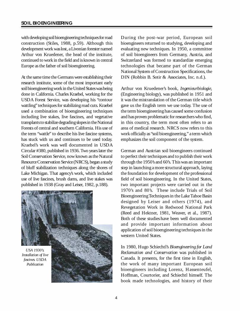
SOIL BIOENGINEERING
between these natural terraces vegetation begins to establish Herbaceous plants usually provide initial vegetative cover on these sites This initial cover also assists in establishment of soil microorganisms Typical succession patterns go from exposed ground through a herbaceous stage to pioneer shrub and tree and finally to a climax tree stage The primary goal is to examine and document these trends Soil bioengineering designs are intended to accelerate site recovery by mimicking or accelerating what is happening naturally
Site Evaluation and Design Checklist There are many soil bioengineering systems Selection of the appropriate technique or techniques is critical to successful restoration At a minimum consider the following
Climatic Conditions bull Precipitation types levels timing and
duration bull Temperatures including extremes
Topography and Aspect bull Slope gradient terrain shape elevation of
project area and direction of sun exposure Climates near the ground can vary considerably within short distances South facing valleys for example receive more direct sun rays causing higher soil temperatures increased evaporation more rapid snowmelt in the spring and generally drier conditions than on the more shaded north facing side This difference will influence erosion rates and the composition and vigor of vegetation
Soils bull Underlying substrate bull Root and water permeability moisture
holding capacity and nutrient availability bull Identify conditions above below or within
your project site which may have an affect on your project and incorporate these considerations into your design
Water bull If applicable stream and fish types affected
by the erosion site bull Location of natural drainage channels and
areas of overland flow from road surface bull Identify areas for safe water diversion bull Note condition of ditch line and culvert inlets
and outlets
Vegetation bull Plant types and amount growing within and
adjacent to the project site This is especially important to identify colonizing species
bull Locations for and preparation of future plant and seed collection
Erosion Process bull Type of mass wasting or surface erosion
features including seepage bull Source of eroding material road fill slope cut
slope landing etc bull Trend of sitendashimproving naturally remaining
uniform or worsening
Project Planning and Implementation Checklist Site Preparation bull Develop and implement a communication
plan to keep all involved interested and informed
bull Establish clear project objectives Have these objectives reviewedfuther developed and approved by participants including the local road manager
bull List all project phases Under each phase catalogue and schedule all work items For each work item list responsible party and the date their tasks must be completed Identify and resolve timing conflicts Build flexibility into the schedule
6
SOIL BIOENGINEERING
bull Sites often require earthwork prior to and during installation of a soil bioengineering system Timing conflicts can occur between scheduling heavy equipment hand labor work plant collection and use
bull Select the right equipment for the job
bull Identify and remove work hazards such as rocks boulders and tree stumps
bull Determine storage and staging areas and access routes for people and machinery to minimize site disturbance and improve efficiency
bull Ensure coordination between heavy equipment operator and handcrew
bull Temporarily divert excess water
bull Stockpile excavated soils for later use and retain or salvage existing vegetation for later use
bull Provide and maintain temporary surface erosion and sediment control measures
Project Work bull Before beginning the project conduct an
on-site field pre-work meeting At a minimum include those with vegetation and soils skills
bull Avoid earthwork in saturated soils Schedule heavy equipment work during periods of low precipitation
bull Collect plant materials during the dormant season Keep them protected from wind and heat Best results are obtained when installation occurs the same day materials are prepared however some believe greater success can be realized if stems are soaked in water five days prior to planting Further research shows that cut stems are still viable after being refrigerated several months prior to planting under the
proper temperature and humidity condition Although opinions differ on length of storage all agree proper storage and use are critical Protecting stems from wind and keeping them cool and moist are essential
bull Inspect project work daily ldquoYou get what you inspect not what you expectrdquo
Plant Materials Living vegetation is the most critical component of a soil bioengineered system Existing vegetation and knowledge of predisturbance and surrounding area plant communities can inform the designer of project limitations opportunities and long term ecological goals Work with local plant experts such as botanists and silviculturalists to select the most appropriate plant species for your project
Which plants to use are affected by the following factors
bull Site characteristics (topography elevation aspect soil moisture and nutrient levels)
bull Existing vegetation bull Intended role of vegetation in the project
such as rooting characteristics bull Growth characteristics and ecological relationships of the plants bull Availability bull Logistical and economic constraints
Plants which can resist mechanical stresses of erosion floods and landslideswhile developinga strongstabilizing root system are best suited for soil bioengineering applications Examples of riparian plants suitable for soil bioengineering work include but are not limited to willows dogwoodscottonwoods big leafmaples spruce cedars aspen and alders
Plants better suited for dryer and poorer soil conditions include bitter brush snowberrywhite pine lodgepole pine vine maple Douglas maple oceanspray red elderberry and salmonberry The best indicator of what plant materials one should consider
7
SOIL BIOENGINEERING
for a soil bioengineering project are the plants growing on or adjacent to the project site Work with local vegetation specialists to understand the limitations and opportunities encountered when stabilizing an erosion site
Most commonlyplant materials are chosen from among those available on the site or nearby Alternatively the soil bioengineer may find an area where the vegetation will be removed or salvaged for future development Logistical concerns are also important in the selection of plant material
A single species may serve the primary structural requirement of the vegetation in a soil bioengineered system However it is preferable to use a mixture of species with varying but complimentary characteristics Benefits of using multiple species include
bull Less susceptible to devastation by disease or pests
bull Offers combinations of deep and shallow rooting species and high and low elevation vegetation
bull Allows the system to respond to changes in site conditions
bull Offers greater diversity and habitat values
Plant Movement Guidelines The reason for setting plant movement guidelines is to increase likelihood of plants surviving growing to maturity and reproducing Chance of success is much greater if locally collected materials are used
Upland plant species Use local seed (collection) zones to identify where best to collect seed cuttings or plants A seed zone is an area having a defined boundary and altitudinal limits within which landform and climate are sufficiently uniform A silviculturalist or botanist will direct you to this source of information Map 1 provides an example of a seed zone map in Washington State
Based on climatic and physiographic information seed zones were developed in 1966 to reduce risk of maladaptating commercial tree species and to provide structure for commercial seed trade Each zone has geographic boundaries and is additionally divided into 500-foot elevation intervals Seed lots are coded by both seed zone and elevation band
When collecting seeds cuttings or plants for smaller projects (perhaps a one-time collection) the elevation band can extend approximately 250 feet above and below the site
Shrubs forbs grasses and riparian species Use watershed boundaries as seed cuttings and plant collection and transplant zones with500-foot elevation intervals Planting seeds cuttings or plants outside the seed zone or watershed should be done only after consultation with a silviculturist or botanist
Gene Pool Conservation Guidelines Just as important as plant movement guidelines are making sure the seed lots cuttings or plant lots are genetically diverse To prevent loss of genes in the population use a minimum of 30 to 50 unrelated donor plants Collecting equal number of seeds cuttings or plants from each donor plant or area will also ensure representation by as many parent plants as possible
Donor plants should also be separated by sufficient distance to reduce risk of relatedness ie originating from the same rhizome or root system or for outcrossing plants having one or both parents in common
8
SOIL BIOENGINEERING
TECHNIQUES FOR PROJECT IMPLEMENTATION
Native Plant Cuttings and Seed Collection Advantage Inexpensive Use of local stock Better adapted to local climate and soil conditions
Disadvantages Can have high mortality if collection and storage not performed correctly Can be expensive
Tools needed Hand pruners hand clippers untreated twine burlap sacks (moistened and lined with wet leaves or mulch) plastic sheeting
For seed collection Paper bags cool dry storage area
Procedure bull Collect from 30 to 50 parent plants in good
condition Never take more than 50 percent of seed or cuttings from a given area
bull Collect an equal number of seeds or cuttings from each plant
bull Use watersheds (and 500 foot elevation intervals) for collection of seeds or cuttings of shrubs forbs grasses and ripariantree speciesThe elevation band can be considered to extend approximately 250 feet above or below the site
bull For plant cuttings use young shoots (1 to 2 years old) Older and larger stems tend to have higher mortality Refer to Plant Materials section for information on preferred plant species
bull Protect cuttings fromwind bycovering with plastic sheeting Protecting stems from wind and keeping them cool and moist are essential
bull Seeds collected should be ripe or mature
Harvesting with loppers Robbin Sotir amp Associates
Harvesting with brushsaw Robbin Sotir amp Associates
Harvesting with chainsaw Robbin Sotir amp Associates
9
SOIL BIOENGINEERING
Note A seed zone is an area having a defined boundary and altitudinal limits within which landform and climate are sufficiently uniform Refer to map 1
Map 1ndashSeed zones
10
SOIL BIOENGINEERING
Salvaging plants USDA Forest Service
Salvaging and Transplanting Native Plants Advantage Inexpensive
Disadvantages Can have high mortality if salvaging and transplanting not performed correctly and timely Soil moisture deficiency and over exposure to air and heat are critical factors in plant mortality
For trees shrubs forbs and riparian species use watershed boundaries as collection zones with 500 foot elevation intervals The elevation band can extend approximately 250 feet above or below the site
Plants should be dormant during salvaging and transplanting
Tools needed A flat-bladed spade metal file (for sharpening the spade) hand clippers (for pruning) burlap sacks (moistened and lined with leaves or mulch) plastic sheeting
Procedure Salvaging bull Locate a small and healthy plant growing by itself
Trees and shrubs growing in clumps connected by underground runners are less likely to survive transplanting
bull Clear area around plant of leaves and twigs Shrubs can be pruned if they have a few long branches (over 4 feet) Have a moist burlap sack nearby lined with wet leaves or mulch
bull Dig in a circle approximately eight inches from the main stem A larger excavated area of one foot may be required if it is a large shrub or seedling (3 to 4 feet high) Gently work the spade under the plantrsquos roots and lift the root ball out on the shovel blade Immediately place the root ball into the moistened burlap sack If you are unable to remove entire root ball collect as much of the root system as possible It is especially critical to protect fine root hairs of the plant It is also important to protect excavated plants from direct air and heat exposure
Transplanting bull Salvaged plants should be planted within two hours
of lifting Keep plants moist and free from air and heat exposure
bull Holes should be dug overly large Recommendation is to dig two times the volume of root ball Larger holes will be required in ldquotighterrdquo soils If available add a small amount of low dose time-release fertilizer and mix into the soil Note For bareroot and container plants do not add fertilizer the first year Planting holes must be deep enough so the downslope side of the rootball is entirely buried
bull Roots should be carefully spread out so none are kinked or circling Protect roots especially fine root hairs on the main root system Add water if availablewhen the plant is half installed to reduce voids and increase root and soil contact If possible water when planting is completed
11
SOIL BIOENGINEERING
Planting vegetation USDA Forest Service
bull On-site soil should be used to backfill the hole Firmly tamp the soil around the plant Be careful not to over compact the soil Once transplanted prune the plant to conserve ldquofuelrdquo for root development Prune to balance tops with roots For example if you cut off roots cut back tops by about12 Use clippings as mulch around the plant
bull Transplanting a microsite Depending on site conditions and project objective it may be preferred to salvage and transplant a small section of ground This ground section usually contains several plants with roots seed soil soil microorganisms and duff materials This technique provides great benefits to the area trying to revegetate For transplanting small sections of ground excavate an area large enough to ldquoplantrdquo the entire piece Lay it in the excavated area and level with adjoining ground Use excavated soil to secure edges of transplanted piece Tap gently in place Whenever possible water the transplant
Planting Containerized and Bare Root Plants Advantages Best application for long term increase in mechanical strength of soils Can be quickly applied to slopes materials are inexpensive creates a rooting zone over time to protect soils from erosion
Disadvantages Can have high mortality if planting not performed correctly Soil moisture deficiency and over exposure to air and heat are critical factors in plant mortality
Containerized and bare root plants must be installed with careful attention to protect their root systems
Tools needed Hoedad or dibble tree planting bag water for root dipping of bare root plants
Procedure bull The planting hole should be dug deep and wide
enough to fully accommodate the natural configuration of the root system
bull The roots should be carefully spread out so none are kinked circling or jammed in the bottom of the planting hole
bull On-site soil should be used to backfill the hole and the plant firmly tamped but not overly compacted into the ground Add water if available to reduce voids that can desiccate roots
12
SOIL BIOENGINEERING
Distribution of seed and fertilizer USDA Forest
Distribution of Seed Fertilizer and Certified Noxious Weed-free Straw or Hay Advantages Can be quickly applied to slopes materials are inexpensive creates shallow fibrous rooting zone in the upper foot or so of the surface profile which binds near-surface soils and protects soil surfaces from surface water runoff wind and freeze-thaw erosive forces
Disadvantages Not adequate alone for mitigating highly eroded surface erosion areas or for landslide stabilization
Seeding should be applied in combination with planting trees and shrubs to provide root reinforceshyment of surface soils Best times to apply include spring and early autumn If project is implemented in autumn it is critical to allow adequate time for good root and leaf development (approximately 4 inches) prior to winter Refer to Natural Resource Conservation Service technical guide for seeding dates available in every US county
Spreading straw mulch USDA Forest Service
Seeding involves application of grass forb and woody plant seed mixes to erosion areas
Tools needed McLeod rake hand seeder protective respiratory mask
Procedure bull Round top edge of slope failure (fig 18) For
project success it is critical to address this ldquoinitiation pointrdquo or chronic source of the erosion A common initiation point for these failures is located at the upper boundary of the site For project success it is critical to remove or round off slope overhang (figure18)
bull Smooth all eroding areas such as rills or gullies In addition prepare a seed bed by slightly roughening area Do this by raking across slope face never downslope Raking downslope can create depressions for channeling water
Slope terracing USDA Forest Service
13
SOIL BIOENGINEERING
bull Create terraces on contour when slopes exceed 35 percent Dig these terraces 10 to 14 inches deep across slope face Spacing usually varies from 4 to 10 feet depending on conditions (fig 2) The objective is to accelerate establishment of plants by reducing slope angle and steepness between each terrace
bull Broadcast seed fertilizer and weed-free straw Make sure your seed is covered with at least 14 inch of soil Seed and fertilize as required by mix directions For example a mix may consist of 1 part seed (annual rye and forb mix) and 3 parts fertilizer (161616) Organic amendments in place of fertilizers also work well Work with local vegetation and soils specialists to determine desirable seed species and soil nutrient needs In addition determine if burying seed is critical for germination
bull Hand spreading of mulch is sufficient However machine application spreads materials more evenly and requires less mulch for full coverage As a result machine application may be more economical than hand distribution
bull In addition to mulching the site it is critical to protect areas from additional surface water flow specifically overland flow from roads Direct water flow away from the project area by constructing crossdrains across the road surface several feet prior to the project area Location and number of crossdrains needed will depend on several factors including road gradient and whether or not the road is outsloped or insloped above project area Crossdrains are cut approximately 6 inches deep across road surface to a vegetated stable point on the fillslope These hand-excavated drains are a temporary measure until heavy equipment is available to dig deeper water diversions An alternative to crossdrains or an additional measure to consider is to install drain rock and allow the water to move through the project area
Live staking Robbin Sotir amp Associates Live Staking Advantages Overtime a living root mat developes soil by reinforcing and binding soil particles together and by extracting excess soil moisture Appropriate technique for repair of small earth slips and slumps that usually have moist soils
Disadvantages Does not solve existing erosion problems (excluding benefits from associated mulch) live staking is not a short-term solution to slope instabilities
Tools needed Hand pruners and clippers untreated twine deadblow or rubber hammer burlap sacks (moistened and lined with wet leaves or mulch)
Procedure Vegetative cuttings are living materials and must be handled properly to avoid excess stress such as drying or exposure to heat They must be installed in moist soil and adequately covered with mulch Soil must be tamped to eliminate or minimize air pockets around buried stems
Installation is best accomplished in late fall at onset of plant dormancy in the winter as long as the ground is not frozen or in early spring before budding growth begins
Live staking involves insertion and tapping of live rootable vegetative cuttings (eg willow cottonwood
14
SOIL BIOENGINEERING
and red-osier dogwood) into the ground If correctly prepared and placed the live stake will root and grow
bull Live cuttings are usually 12 to 1 12 inches in diameter and 18 to 36 inches long Materials must have side branches cleanly removed and bark intact Young shoots 1 to 2 years of age work best Older and larger stems have a higher rate of mortality but can be successful with additional treatment eg bark scoring and rooting hormones
bull Cut basal end at an angle for easy insertion into the soil Cut top square (figure 1)
bull Best results are obtained when installation occurs the same day stakes are prepared however some believe greater success can be realized if stems are soaked in water 5 days prior to planting Further research shows that cut stems are still viable after being refrigerated several months prior to planting Although opinions differ on length of storage all agree proper storage and use are critical Protecting stems from wind and keeping them cool and moist are essential
bull Orient buds up
bull Tap live stake into the ground at right angles to the slope Installation may be started at any point on the slope face
bull Two-thirds to three-quarters of the length of the live stake should be installed into the ground and soil firmly packed around it after installation (figure 1) The more stem exposed to air the more moisture is lost This moisture is critical for root development
bull Install live stakes 2 to 3 feet apart using triangular spacing Density of installation should range from 2 to 4 live stakes per square yard
bull Be careful not to split stakes while tamping them into the ground Covering the stake with a 2 by 4-inch wood section will cushion the blows thus protecting the stake from splitting Trim damaged top area
bull Rebar can be used to make a pilot hole in firm soil Tamp the live stake into the ground with a deadblow (hammer filled with shot or sand) or rubber mallet
Figure 1ndashLive stake
14 to 13 ldquo Flat top
12 to 1-12 ldquo
18 to 36 ldquo
Angle
Bury 23 to
34 of stem
not to scale
15
SOIL BIOENGINEERING
Hand excavated terraces for erosion control blanket USDA Rolling out erosion control blanket USDA Forest Service Forest Service
Installation of Erosion Control Blanket Advantages Excellent for mitigating surface erosion The blanket offers immediate and uniform slope protection from rain and overland water flow if it is installed in full contact with the soil surface
Disadvantages Can be labor intensive and expensive Requires numerous wood stakes or livestems Too much grass within the blanket will lead to over competition for moisture sunlight and nutrients and may result in high tree and shrub mortality
Installation of erosion control blankets involves site preparation trenching application of grass andor forb seed mix and fertilizer and installation of fabric This technique is suitable for treating surface erosion areas especially fillslopes where there is a concentration of surface water runoff (figure 3)
Tools needed McLeod rake hand seeder 6-inch spikes and 2-inch pieces of rubber or fire hose hand prunners and clippers heavy duty scissors deadblow or rubber hammer
Procedure bull Round top edge of slope failure (figure 18) For
project success it is critical to address initiation point or chronic erosion source of the slope failure The common initiation point for these
failures is located at the upper boundary of the site For project success it is critical to remove and or round off slope overhang (figure 18)
bull Smooth all eroding areas such as rills or gullies In addition roughen entire site Do this by raking across and not downslope Raking downslope can lead to channeling water
bull Create a small berm on road edge (figure 2)
bull Excavate terraces 10 to 14 inches deep and 5 feet apart (figure 2)
bull Broadcast seed and fertilizer on treatment area as required by mix directions An example one seed mix may include 1 part annual rye and 3 parts 161616 fertilizer Organic amendments can be used in place of inorganic fertilizers
bull Roll out blanket parallel with road between trenches Fabric edges should lay evenly across bottom and top trenches Begin matting installation at bottom two trenches (figure 2)
bull Follow these directions for remaining rows The upper row of fabric should overlap the lower row Lay edge of top row of fabric into shallow terrace created while excavating the berm at road edge (figure 2)
16
SOIL BIOENGINEERING
bull To secure fabric into road edge nail 60D spikes through a hose piece washer If road surface is not too compacted use dead wood stakes instead of nails Nail or stake every 3 to 4 feet across top row of fabric at road edge (figure 2) Once nailed rake bermed soil back over matting edge Note Check with road manager to ensure maintenance activities will not require blading road edge at fabric site Road blading would lead to tearing out sections of the project If this is a major concern install upper edge of fabric a few 4 to 6 inches below the road edge
bull To secure fabric to slope face install live stakes into fabric across slope and through terraces
Optimum spacing of these stakes ranges from 2 to 3 feet Maximum spacing between stakes should not exceed 4 feet (figure 3)
bull Tamp live stakes in leaving 14 to13 of stem above ground and 34 to 23 below ground (figure 1) Trim stakes if more than 13 is exposed Average length of stake ranges from 18 to 36 inches Stakes should be flatcutontopand diagonalcuton bottom so they will be installed correctly and easily (figure 1) Remove top sections of stakes damaged during installation If you are not working in moist soil eg riparian area the willows will not survive In these cases it would be more cost effective to use wood stakes instead
CutslopeShallow terrace
6rdquo berm
Cutslope
Nail and washer 3rsquo to 4rsquo apart
Roadbed
Overlap matting on terraces
Terrace 10rdquo to 14rdquo deep
5rsquo ft
Matting
5rsquo ft
Roadbed
not to scale
Figure 2ndashInstallation of erosion control blanket
17
SOIL BIOENGINEERING
Roadbed Terraces
Side view
Terrace
Nails or stakes Roadbed
Nails or stakes
Terrace
not to scale
Live cribwall one month after construction USDA Forest Service
Figure 3ndashInstallation of erosion control mat
Construction of Live Cribwalls Advantages Appropriate at base of a cut or fillslope where a low wall or log may be required to stabilize toe of the slope and reduce slope steepness Useful where space is limited and a more vertical structure is required Provides immediate protection from erosion while established vegetation provides long term stability Aesthetically more pleasing and possibly less expensive compared to conventional gabion baskets
Disadvantages Not designed for or intended to resist large lateral earth stresses Depending on soil quality of cutslope may have to use commercial fill material Can be labor intensive and expensive to construct Can have high mortality if willow stems are not collected when dormant not cut and used the same day or mishandled in transfer
A live cribwall consists of a hollow box-like interlocking arrangement of untreated log or timber members The structure is filled with suitable backfill material and
18
SOIL BIOENGINEERING
Live cribwall during construction USDA Forest Service
layers of live branch cuttings such as willow or dogwood which root inside the crib structure and extend into the slope Cribwall should be tilted or battered back if constructed on a smooth evenly sloped surfaceOnce live cuttings root and become established subsequent vegetation gradually takes over the structural functions of wood members (figure 8) Coordinate with road manager prior to construction Often their primaryconcern is the structure will block water flow in the ditch line Make sure the design takes this concern into consideration
Basic design ideas are from Sotir and Gray 1982 and 1992 The following description and guide however includes several changes
Tools needed Chainsaw McLeod rake deadblow or rubber hammer 8 to 12 inch spikes or rebar shovels hand prunners and clippers
Procedure A Starting at lowest point of the slope excavate
loose material until a stable foundation is reached
B Place first course of 4 to 8 inch diameter logs or timbers at front and back of excavated foundation approximately 4 to 5 feet apart and parallel to the slope contour These are your main beams (figure 4)
C Lay 4 to 5 foot long and 4 to 8 inch diameter cross beams (either conifer or hardwood) across
main beams Spike or wire cross beams to main beams front and back (figure 5)
D Fill inside of main frame with soil Note Some gravel and rock can be used however willows will have more vigor if soil conditions are favorable If consequence of project failure is high it is critical to use commercial fill material
E Lay 5 foot long and 12 to 3 inch diameter trimmed live cut branches (3 to 6 inches apart depending on soil moisture) between cross beams and into cutbank On the bottom layer lay the basal ends of live cut branches under back main beam and on top of front main beam (figure 5 and figure 6) Note The purpose is to take full advantage of excess water at slope base If you do not have excess soil moisture conditions you do not have to lay butt ends of branches under back main beam Instead you can lay them directly over this beam
F Following ldquoArdquo and ldquoBrdquo start second layerThe onlydifference is set main beams back the width of bottom main beams and into cutbankThis allows cribwall to lean into cutbank and keeps fill material from falling out of front of cribwall (figure 7)
G Fill frame with soil
H Lay 4 to 5 foot long live cut branches on top of front and back main beams and between cross beams Lay these live branches approximately 3 inches apart (figure 5) Spacing of branches depends on availability of moisture and can range from side-by-side to 6 inches apart
I Continue constructing layers following ldquoErdquoldquoFrdquo and ldquoGrdquo until you reach specified height
J If needed construct wings or flanges to catch soil at structurersquos edges and to key in the structure to the slope face
19
main
ain b
SOIL BIOENGINEERING
K Cribwall should be tilted back if constructed on a smooth evenly sloped surface This can be accomplished by excavating the back of the stable foundation (closest to the slope) slightly deeper than the front to add stability to the structure (figure 8)
L May be constructed in a stair-stepped fashion with each successive layer of timbers set back 6 to 9 inches toward back cut slope face from previously installed course
Half Cribwall bull To insure minimum road width of 14 feet it
may be necessary to construct a half cribwall This is done by cutting cross beams width in half from 4 to 2 feet wide at base of cribwall (figure 7) and gradually increasing cribwall width by layer as desired cribwall height is being achieved (figure 7 and figure 8)
Toe Log Technique bull The toe log technique is a handy tool for very
small cutslope erosion features eg 10 feet high by 15 feet wide Place a 20 to 24 inch diameter log along the base of the erosion site Lay 5 foot long and 12 to 1 inch diameter live cut branches (side-by-side to 6 inches apart depending on soil moisture) on top of the log and into cutbank (figure 7) The purpose is to take full advantage of excess water at slope base Place soil behind the log with soils from the slope face Toe logging is a quick and effective tool in stabilizing base of slopes However it is only effective when sites are small and only slightly over steepened It is very important to use the right size log for existing slope condition
When constructing a live cribwall half cribwall or toe log the initiation point of the slope failure must be addressed The common initiation point or source of chronic erosion for these failures is located at the upper boundary of the site For project success it is critical to remove or round off slope overhang (figure 18)
Rear beam
Front m eam
Cutslope
Edge of cutbank
Road
For half cribwall
Ditch
20
not to scale
4-8 diameter
Figure 4ndashLive cribwall construction
20
SOIL BIOENGINEERING
Rear main beam
Front main beam
Cutslope
Edge of cutbank
Road
3 apart
Ditch
not to scale
4 to 8
20
5 long
8 to 12spike
12 to 3 diameter 5 in length
4-8 diameter
Figure 5ndashLive cribwall construction
Crossbeam
Back mainbeam
Spikes Ditch
Roadbed
Cutslope
Willow on top of front main beam
Willow under rear main beam
Existing roadbed
not to scale
Figure 6ndashLive cribwall construction
21
SOIL BIOENGINEERING
3rsquo to 5rsquo
Constructed into slope
minimum of 6rsquo 8 to 12rdquo
Ditch
Roadbed
Half cribwall
1-12 to 3rdquo 4rsquo diameter
Ditch
Roadbed Ditched
Toe log 20-24rdquo diameter 2rsquo
Figure 7ndashLive cribwall-stepped full half and toelog construction
Evacuated cutslope
New slope
Roots
5rsquo to 6rsquo
Soil
Ditch Roots
Figure 8ndashLive cribwall battered construction
22
SOIL BIOENGINEERING
Live facines illustration Kraebel Live Fascine Advantages Immediately reduces surface erosion or rilling Suited to steep rocky slopes where digging is difficult Capable of trapping and holding soil on the slope face thus reducing a long slope into a series of shorter steps Can also be used to manage mild gully erosion and can serve as slope drains when bundles are angled Best suited for moist soil conditions Note Where soil moisture is not sufficient for supporting live materials fascines can also be constructed of plant stems not intended for rooting The bundle still traps and holds sediments and reduces slope length and steepness between terraces Plant vegetation on andor between the terraces As inall projects living recovery is dependent on successfully establishing the vegetation
Disadvantages On steep or long slope lengths high runoff velocities can undermine live fascines near drainage channels Significant quantity of plant material is required and can dry out if not properly installed Best suited for riparian moist soil conditions Otherwise high plant mortality could occur
Live fascines (Kraebel1936 and Sotir and Gray1982 and 1996) also referred to as contour or willow wattling are long bundles of branch cuttings bound together into sausage like structures (figure 9)
Tools needed Hand pruners and clippers untreated twine (not hemp) pulaski or hazel hoe deadblow or rubber mallet McLeod rake dead plant materials
Procedure bull Excavate 10 to 14 inch deep terraces along slope
contour and the full width of treatment area Spacing of terraces averages between 5 to 7 feet with a goal of 11 slope Terrace placement is a function of slope and should be calculated Terrace excavation and live fascine installation should progress from base of project up to slope crest
bull Bundle willow branches Other species such as red-osier dogwood or snowberry can be used For best results cut and use plant materials same day (See comments in Live Staking about collection and timing of installation) Butt ends and top ends are usually laid alternately until a bundle has been created which looks like an 8 to10 inch wide sausage Plant materials should be about 12 to 5 inches in diameter and about 4 to 8 feet in length (figure 9) Bundles are then tied together using up to 20 percent dead material and bound with untreated lengths of twine Note Use of up to 20 percent dead materials retains structural properties of live fascine and bundle still has enough live material to grow
bull Lay bundle across terrace splice together ends of each (figure 9) and do not overlap Bundles should be 14 to 13 exposed
Live facine installation USDA Forest Service
23
SOIL BIOENGINEERING
Live facine installationndashangled Robbin Sotir amp Associates
bull Next live stake the downslope side of terraces at middle and overlap points to hold live fascines in the terrace Be sure to splice ends of bundles In addition place wood stakes through live facines every two feet Wood stakes should be driven directly through bundle center (figure 9) Live willow and wood stakes should be 1 to 3 inches in diameter and 2 to 3 feet long Stakes should be flat cut on top and diagonally cut on bottom to ensure appropriate and easy installation Remove top section of live stakes damaged during installation
bull Stand in completed terrace and begin excavation of second terrace This process will allow soil from second terrace to cover first row Walk on wattles to compact and to gain good soil fascine contact
bull If available water fascine to work soil into the bundle for increased soil contact and decreased desiccation
bull Move upslope to next terrace alignment and repeat process (figure 9)
1
2
3
Untreated Twine Ties
Stems 12 to 1-12 diameter 8 to 10 diameter
4 to 8 length not to scale
Live facine Wood stake
Live stake
Spacing averages 5rsquo to 7rsquo
face measurement
Figure 9ndashLive fascines
24
SOIL BIOENGINEERING
Brushlayering Advantages Breaks up slope length into a series of shorter slopes separated by rows of brushlayer Reinforces soil as roots develop adding resistance to sliding or shear displacement Reinforces soil with unrooted branch stems Provides slope stability and allows vegetative cover to become established Traps debris on slope Aids infiltration on dry sites Dries excessively wet sites
Disadvantages Recommended on slopes up to 21 in steepness and not to exceed 15 feet in vertical height Labor intensive
Brushlayering (Sotir and Gray 1982 and 1992) consists of placing live branch cuttings in small terraces excavated into the slopeTerraces can range from 2 to 3 feet wide This technique is similar to live fascine systems because both involve cutting and placement of live branch cuttings on slopes The two techniques differ in the orientation of the branches and depth they are placed in the slope In brushlayering cuttings are oriented perpendicular to slope contour (figure 10) This placement is more effective fromthe pointof view of earth reinforcement and mass shallow stability of the slope
Tools needed Hand pruners and clippers untreated twine (not hemp) pulaski or hazel hoe shovel deadblow or rubber hammer McLeod rake
Digging terraces for brushlayer installation Robbin Sotir amp Associates Brushlayer installation Robbin Sotir amp Associates
Procedure bull Begin project at base of treatment area Excavate
terrace so that approximately 14 of average brush length extends beyond slope face Do not over excavate This technique can trigger soil movements during installation It is important therefore to perform installation in phases and to avoid excavating more area than is necessary to install plant materials (figure 10)
bull Lay an appropriate amount (ie 20 to 25 stems per yard) of single or multiple mix of live brush species along trench sidewall Length of stems can vary from 3 to 4 feet and diameter 12 to 3 inches (figure 10)
bull Stand in completed terrace and begin excavation of second terrace This process allows soil from second terrace above to cover first brushlayer row Compact and slightly mound soil behind brushlayers
bull Move upslope to next trench alignment and repeat process (figure 10)
Brushlayers modified with log terracing installing a short small log (figure 10) can modify brushlayers The log provides additional support to the brushlayer reduces slope angle and serves as a small terrace to ldquocatchrdquo rolling rocks rather than allowing them to roll down the slope and damage vegetation
25
Slope
Installation fall line
direction
SOIL BIOENGINEERING
Brushlayering just after installation Robbin Brushlayering 3 months after installation Sotir amp Associates Robbin Sotir amp Associates
Spacing averages 5-7
Stems 1 14 to 2
diameter
2
3
Spacing 4 to 10
Plant shrubs and trees throughout slope face
To reduce slope angle Live branch cuttings
Log (4 to 6 diameter)
Brushlayer
Length = 2 to 6
Stake
Brushlayer with log terrace
not to scale
Figure 10ndashBrushlayering and brushlayering w log terrace
26
SOIL BIOENGINEERING
Willow fencing with brushlayering USDA Forest Service
Willow Fencing Modified with Brushlayering Advantages These structures reduce slope angle providing a stable platform for vegetation to establish Willow fences trap rolling rocks and sliding debris and protects vegetation growing lower on the slope Willow fences provide support for small shallow translational or rotational failures Sites where fine textured soils can provide ample summer moisture or where seepage of groundwater provides moisture are suitable for willowbrushlayering fence installations These structures can also be constructed on dryer sites however expect high willow mortality In these situations the willow shelf is considered a temporary planting platform It is important therefore to establish deeper rooting shrubs and trees within the shelf When the structure begins to decay root systems of other plants will serve as the permanent feature
Disadvantages Significant quantity of plant material is required Moist site conditions are required for the fence to sprout and grow
Willow fencing with brushlayering is essentially a willow fence supported on a short brushlayer Specifically it is a short retaining wall built of living cuttings with a brushlayer base (figure 11) Willow fencing can also be used without base brushlayering (Polster 1998)
Tools needed Hand pruners and clippers pulaski or hazel hoe McLeod rake deadblow or rubber hammer wood stakes or rebar
Procedure Brushlayering bull Begin project at base of treatment area Excavate
16 to 20 inch deep trenches along slope contour and for full width of treatment area Spacing of trenches averages between 5 to 8 feet full measurement depending on site conditions This technique can cause additional erosion during installation therefore it is important to construct project in phases and to avoid excavating more area than is necessary to install plant materials (figure 11)
12 to 2 diameter
Willow fencing
18 to 36 long stakes 2 to 3 diameter
Brushlayer
18 to 36 long cuttings 1 2 to 2 diameter
Figure 11ndashWillow fencing modified with brushlayering
27
SOIL BIOENGINEERING
bull Lay live brush stems along base of trench Length of stems average 16 inches in length and diameter of 12 to 2 inches Approximately 14 of average brush length should extend beyond slope face (figure 10)
Willow fencing bull Install supporting 18 to 36 inch long wood
stakes cuttings or rebar Average diameter of stakes ranges from 2 to 3 inches
bull Place a few shrub cuttings 18 to 36 inch long and 12 to 2-inch diameter cuttings behind these supports
bull Place enough soil behind these supports to hold the shrub cuttings in place
bull Stand in the trench and begin excavation of second row This process will allow soil from second trench to cover first willow fencing brushlayer row
bull Compact and slightly mound soil on brushlayer and behind willow fence
bull As more soil is added add additional cuttings until the final height of the fence is achieved A goal should be to construct a 21 slope or less between the top of the willow fence and the bottom of the one above
bull Move upslope to next trench alignment and repeat process (figure 11)
Branchpacking just after installation Robbin Sotir amp Associates
Branchpacking Advantages As plant tops grow branchpacking system becomes increasingly effective in retarding runoff and reducing surface erosion Trapped sediment refills localized slumps orholeswhile roots spreadthroughout the backfill and surrounding earth to form a unified mass (figure 12)
Disadvantage Not effective in slump areas greater than 4 feet deep or 5 feet wide
Branchpacking (Sotir and Gray 1992) consists of alternating layers of livebranch cuttings and compacted backfill to repair small localized slumps and holes (figure 12)
Tools needed Hand pruners and clippers deadblow or rubber hammer untreated twine McLeod rake shovel wood stakes
Branchpacking just after installation Robbin Sotir amp Associates
28
SOIL BIOENGINEERING
Branchpacking post installation Robbin Sotir amp Associates
Procedure bull Starting at lowest point drive wooden stakes
vertically 3 to 4 feet into the ground Set them 1- to 1 12 -feet apart Wooden stakes should be 5 to 8 feet long and made from 3-to-4 inch diameter poles or 2 by 4 lumber depending upon depth of particular slump or hole
bull Place a layer of live cut branches 4 to 6 inches thick in bottom of hole between vertical stakes and perpendicular to the slope face (figure 12) Crisscross branches with growing tips generally oriented toward slope face Some basal ends of branches should touch the back of the slope
bull Install subsequent layers with basal ends lower than the growing tips of the branches This is to insure developing root systems will be located at water collection points on the slope
bull Each layer of branches must be followed by a layer of compacted soil to ensure soil contact with branch cuttings
bull Final installation should match existing slope Branches should protrude only slightly from the filled face
bull The soil should be moist or moistened to insure live branches do not dry out
1 to 1-12
Live branch cuttings 14 to 2 diameter
Compact fill material
Wooden stakes 5 to 8 long 2 x 4 lumber driven 3 to 4 into undisturbed soil
4 to 6 inch layer of live branch cuttings laid criss cross and
touching back of hole
Live branch cuttings should protrude slightly from
backfill area
Several weeks or months later
spacing not to scale
Figure 12ndashBranchpacking
29
SOIL BIOENGINEERING
3 to 4 inch layer of live branch cuttings laid in crisscross and touching undisturbed soil on gully bed
Several weeks later
Live branch cuttings 1 to 2 in diameter
Compacted fill material 6 to 8 layer
Gully bed
Figure 13ndashLive gully repair
Live Gully Repair Advantages Offers immediate reinforcement to compacted soil reduces velocity of concentrated flow of water and provides a filter barrier to reduce rill and gully erosion
Disadvantages Limited to rills and gullies which are a maximum of 2-feet wide 1-foot deep and 15- feet long
Live gully repair (Sotir and Gray 1992) utilizes alternating layers of live branch cuttings and compacted soil to repair small rills and gullies Similar to branchpacking this method is more appropriate for repair of rills and gullies
Tools needed Hand pruners and clippers shovel McLeod rake untreated twine
Procedure bull Starting at lowest point of the slope place a 3shy
to 4-inch thick layer of live cut branches at lowest end of the rill or gully and perpendicular to the slope (figure 13)
bull Cover with 6-to 8-inch layer of soil
bull Install live cut branches in a crisscross fashion Orient growing tips toward slope face with basal ends lower than growing tips
bull Follow each layer of branches with a layer of compacted soil to ensure soil contact with live branch cuttings
30
SOIL BIOENGINEERING
Figure 14ndashVegetated geotextile
Vegetated Geotextile Advantages Retards rill and gully erosion stabilizes fill banks Is less expensive than other retaining walls such as gabion or Hilfiker baskets
Disadvantage Can be expensive if heavy equipment required
Synthetic or organic geotextile wrapped around lifts of soil with a mix of live branches placed between layers There are numerous opportunites of blending geotechnical-engineered systems with soil bioengineering The following is one example
Tools needed Backhoe geotextile hand pruners and clippers McLeod rake shovel untreated twine
Procedure bull Excavate lower edge of slope break and bench
backcut Compact the soil layer Note Structural integrity is dependent on compacted soil layers Even with mechanized firming soils support live cuttings
bull Lay first layer of geotextile down into the bench
bull Fill lowest lift with gravel fold back and stake securely
bull Fill subsequent layers with soil and layers of live cut branches (figure 10) and alternate with lifts (figure 14) Each layer must be compacted
bull The structure can be built with a vertical face or stair-stepped and sloped back into the hillside
31
SOIL BIOENGINEERING
Installation - cutslope stabilzation with log terracing USDA Forest Service
Log Terracing Advantages Logs create terraces reducing length and steepness of slope provides stable areas for establishment of other vegetation such as trees and shrubs
Disadvantages Labor intensive and with potential safety hazards
Tools needed Chainsaw PV pole blocks and cable power winch shackles and chokers pulaski Mcleod and shovel wood stakes hand pruner and clippers traffic control signs
Procedure bull The technique utilizes alternating terraced logs
to stop surface erosion on eroding slopes Stopping the erosion is critical for successful revegetation efforts Specifically log terracing shortens slope length and gradient between each structure providing stable planting areas throughout most of the slope face (figure 15)
bull Prior to beginning a log terracing project place traffic control signs several hundred feet on both sides of your project area Then climb slope to locate and remove potential safety hazards These hazards include loose tree root wads unstable rocks and boulders This inspection will also provide a different visual
perspective of the site This ldquotop-downrdquo viewpoint is usually the best place to formulate your project design
bull Begin log terracing at the base of the slope and work your way uphill This should prevent undercutting of any terrace or log you place above It also provides a stable and secure footing area for project work
bull Log terracing consists primarily of 3 main steps These steps include moving installing and anchoring logs to specified points on an eroding hillside
Moving bull Try not to cause any additional erosion or
damage log terraces you have already excavated This can be accomplished by setting up a skyline or carefully using a straight dragline with block and cable
Installation bull Use a minimum of 12-inch diameter logs
Sixteen or 20-inch diameter logs work best The most common error in log terracing is using logs that are too small in diameter
bull Use existing slope features such as tree stumps rock outcroppings or natural slope benches to secure one or both ends of the logs These natural features make project work easier safer and work better than stakes or rebar for keeping the log in place on the slope
bull Excavate terraces 13 the width of the log diameter deep and for full length of the log With rope (or cable) blocks and winch place the logs into position (figure 16)
Anchoring bull Depending on site conditions attempt to space
log terraces 10 to 20 feet apart
32
SOIL BIOENGINEERING
bull Anchor logs into the slope using 3-to 5-inch should be inserted into the ground Bend over diameter wood stakes or 34 inch rebar any excess rebar
bull Stake length should be 4 times the diameter of the log A 12-inch diameter log for example would require 48-inch long stakes and a 16shyinch diameter log 64-inch long stakes
bull Once in place drive stakes vertically into slope just below the log Two thirds of the stake should be driven into the ground These stakes should be spaced every 4 feet across the length of the log (figure 17) Another recommended technique is to drill holes through the log and anchor with rebar Two thirds of total length
bull When utilizing tree stumps and rock outcroppings for anchor points gaps may occur between log and soil surface This gap must be filled To do so excavate a trench uphill from the log and place a smaller log flush with the log structure (figure 17)
bull There are many possible patterns for log terracing The following 3 have proved useful for stabilization efforts (figure 15) Whatever pattern utilized it is absolutely critical no gaps exist between the log and soil surface
Erosion site Erosion site Erosion site
Retaining structure Retaining structure Retaining structure
15-20
15-20
Shortened slope distance 50 failure
width
Rock
20
Treestump
Staggered Pattern Ladder Pattern Building Block Pattern
not to scale
Figure 15ndashLog terrace installation
33
SOIL BIOENGINEERING
Staggered Using logs with lengths greater than 50 percent of the width of the erosion site These logs should overlap each other and be anchored into stable soils on either side of the failure site
Ladder Logs extend across full width of erosion site and should be anchored into stable soils on either side of failure site
Building block This method best mimics what happens naturally on an eroding slope Begin the project at the slope base This area is stable and will provide a secure base to build off of as you work your way up slope There is no set pattern Design and log placement pattern will evolve as the project progresses Be creative
bull Once the slope has been stabilized with log terracing it is critical to address the upper portion of the slope failure This area is often referred to as the slope overhang Addressing this area is critical since it is the source of the surface erosion Without removing this erosion source project success is unlikely Cut away the overhang so slope angle will allow seed to germinate and plants to establish Try to angle the slope to blend with the new slope gradient created with log terracing Often this will require a cut 5 to 6 feet upslope This is the most difficult portion of a log terracing project and will often result in removing vegetation This vegetation however can be transplanted to other areas on the slope
34
SOIL BIOENGINEERING
Use of existing slope features
Stump
Rock
Front view trench construction
Trench
Place log 13 of diameter deep
Slope
Place log 13 of diameter deep
Trench construction side view
Stakes
not to scale
Figure 16ndashLog terrace construction
Formula A 12 diameter log needs 48 long stakes
Trench
Stake 13 above
Stake 23 below
Stakes
Front view
Erosion site
Log
Cutslope
Roadbed
Vertical placement
Side view
Erosion site
Stake 13 above ground
Stake 23 below ground
Ground level
Gap
Ground level
Filler log
not to scale
Figure 17ndashAnchoring and filling gaps
35
SOIL BIOENGINEERING
Roadbed Ditch
Cutslope
Fill slope
Slope overhang
Slope overhang
Area to remove
Area to remove
not to scale
Figure 18ndashRemoval of slope overhang
36
SOIL BIOENGINEERING
Bender Board Fencing Advantages These structures reduce slope angle providing a stable platform for vegetation to establish Like willow fencing bender board structures trap rolling rocks and sliding debris and protects vegetation growing lower on the slope Bender board fences provide support for small translational or rotational failures
Dry sites where soils receive very little precipitation this type of structure The bender board shelf is considered a temporary planting platform It is important therefore to establish deeper rooting shrubs and trees within the shelves When the structures begins to decay root systems of other plants will serve as the permanent feature
Disadvantage Significant quantity of plant material is required
Redwood or cedar bender board fencing is essentially a fence supported on a short layer of shrub or tree stems Specifically it is a short retaining wall built of redwood or cedar bender fencing with a stem layered base
Tools needed Hand pruners and clippers pulaski or hazel hoe McLeod rake deadblow or rubber hammer wood stakes
Procedure Stem Layered Base bull Begin project at base of treatment area Excavate a
24-inch deep terrace along slope contour and for full width of treatment area The back of the terrace should be dug with an approximate 70 degree angle To allow ample planting platforms space terraces about 5 feet apart
bull Lay 2 feet 6-inch long stems and 2 feet 6-inch long wood stakes (5050 mix) 2-inches apart and for full length of terrace Diameter can range from 12 to 2-inches Approximatly 6-inches will extend beyond slope face
Bender board Fencing bull Drive supporting 4 foot 6-inch (2 by 2) long stakes
2 to 3 feet into ground spaced 1 foot apart and perpendicular to the slope Rebar may be used instead of wooden stakes
bull Weave 10 foot long bender boards through these stakes until the wall reaches a height of 2 feet Once complete the bender board fence wall should be at a 15 degree angle to the slope Note As shown in photo some bender board are too brittle to weave
bull Once the wall frame is constructed carefully rake enough soil into the terrace to cover the stem layered base
37
SOIL BIOENGINEERING
bull Stand in terrace and begin excavation of second bull Move upslope to next terrace alignment and row This process will allow soil into the terrace repeat process to cover the stem layered base
bull A goal should be to construct a 21 slope or less between the top of the bender board fence wall and the bottom of the one above
10 foot long bender boards 14 thick 3-12 wide
2-6 long stakes spaced 3 apart
2 high seven bender boards
2 wide terraces spaced 5 apart
not to scale
4-6 post buried 2-3
Figure 19ndashBender board fencing
38
SOIL BIOENGINEERING
REFERENCES CITED
Bach David H and MacAskill IA 1984 Vegetation and Landscape Engineering Granada London
Bennett Francis W 1975 Methods of Quickly Vegetating Soils of Low Productivity Construction Activities US Environmental Protection Agency Washington DC
Brosius Myra 1985 ldquoThe Restoration of an Urban Stream Using Geomorphic Relationships and Biotechnical Streambank Stabilizationrdquo Athens GA University of Georgia Thesis
Chandler RJ 1991 Slope Stability Engineering Institution of Civil Engineers Thomas Telford Publishing Company
Chatwin S D Howes and D Swantson 1994 A Guide for Management of Landslide Prone Terrain in the Pacific Northwest Second edition Ministry of Forests Crown Publications Victoria BC
Christensen M and J Jacobovitch 1992 Revegetation Projects Everything You Wanted to Know About Live Staking Unpublished report for King County Dept of Public Works Surface Water Management Div Seattle WA
Coppin NJ and IG Richards 1990 Use of Vegetation in Civil Engineering Butterworths London England
Coppin Nick J and R Stiles 1989 The Use of Vegetation in Slope Stabilization Landscape Design with Plants Second Edition ed by Brian Clouston Boca Raton Florida CRC Press 212-234
Edlin HL 1949 Woodland Crafts in Britain BT London Batsford Ltd London
Finney Kevin P 1993 BioEngineering Solutions A Tool for Education Eugene OR University of Oregon Thesis
Finney K 1993 History of Soil Bioengineering Eugene OR Masters Thesis University of Oregon Thesis
Gray DR and AT Leiser 1982 Biotechnical Slope Protection and Erosion Control New YorkVan Nostrand Reinhold Company New York
Gray DH Leiser T Andrew and C A White 1980 Combined Vegetative Structural Slope Stabilization Civil Engineering 50(1)82-85
Gray D R and Sotir RB 1996 Biotechnical and Soil Bioengineering Slope Stabilization John Wiley and Sons Inc
Greenway DR 1987 Vegetation and Slope Stability In Slope Stability John Wiley and Sons Ltd Chapter 6
41
SOIL BIOENGINEERING
Johnson AW and JM Stypula eds 1993 Guidelines for Bank Stabilization Projects In the Rivetine Environments of King County County Department of Public Works Surface Water Management Division Seattle WA
Kraebel CJ 1936 Erosion Control on Mountain Roads USDA Circular No 380 Washington DC USDA
Kraebel CJ 1933 Willow Cuttings for Erosion Control Technical Note No 1 Berkely California USDA California Forest Experiment Station
Larson FE and WE Guse 1981 Propagating Deciduous and Evergreen Shrubs Trees and Vines with Stem Cuttings Pacific Northwest Coop Ext Pub PNW152
Leiser Andrew T J J Nussbaum Kay Burgess Paul Jack and W Thornhill 1974 Revegetation of Disturbed Soils in the Tahoe Basin California Department of Transportation Sacramento California
Lewis EA and LW Ogg 1993 Soil Bioengineering Project Descriptions Unpublished report for Olympic National Forest Hood Canal Hanger District
Leys Emil 1978 Wilhelm Hassenteufel 80 Years Old Garten und Landschaft in China Vol 4 Part 3 Cambridge The University Press
Maleike R and RL Hummel 1988 Planting Landscape Plants Wash State Univ Coop Ext Pub EB1505
Polster Environmental Services 1998 Soil Bioengineering for Forest Land Reclamation and Stabilization British Columbia Ministry of Forests
Robbin B Sotir amp Associates A Brief History of Soil Bioengineering Unpublished and undated manuscript
Schiechtl Hugo 1980 Bioengineering For Land Reclamation and Conservation Edmonton Canada The University of Alberta Press
Schiechtl H M and R Stern 1997 Ground Bioengineering Techniques for Slope Protection and Erosion Control Blackwell Science Publications ISBN 0-632-04061-0
Sotir RB and DH Gray 1992 Soil Bioengineering for Upland Slope Protection and Erosion Reduction Engineering Field Handbook Soil Conservation Service Chapter 18
Stiles Richard (172) 57-61 1988 Engineering with Vegetation Landscape Design (172) 57-61
Stiles Richard1991 Re-inventing the Wheel Landscape Design (203)
42
SOIL BIOENGINEERING
Weaver WE and MA Madej 1981 Erosion Control Techniques Used in Redwood National Park In Davies TRH and AJ Pearce eds Erosion and Sediment Transport in Pacific Rim Steeplands Washington DC Intrsquol Assoc Hydrological Sciences 640-654 IAHS-AISH Pub 132
Westmacott Richard 1985 The Rediscovered Arts of Twilling and Wattling Landscape Architecture 75(4)95-98
White Charles A and AL Frank S 1978 Demonstration of Erosion and Sediment Control Technology Lake Tahoe Region of California EPA-6002-78-208 Municipal Environmental Research Laboratory Office of Research and Development US Environmental Protection Agency Cincinnati Ohio
Ziemer RR 1981 Roots and the Stability of Forested Slopes In Davies TRH and AJ Pearce eds Erosion and Sediment Transport in Pacific Rim Steeplands
43
SOIL BIOENGINEERING
About the Authorhellip
Lisa Lewis graduated in 1987 from Fort Valley State University Fort Valley Georgia with a Bachelor of Science degree in Soil and Plant Sciences Lisa began her career with the Forest Service in August 1987 on the Hood Canal Ranger District She continued her career in the Pacific Northwest and since 1998 she has been a soil scientist with the National Riparian Service Team (NRST) As a member of the NRST Lisa provides training and technology transfer consulting and advisory services and program review for riparian restoration nationwide She specializes in road management issues and soil bioengineering techniques
Library Card
Lewis Lisa 2000 Soil bioengineeringmdashan alternative to roadside managementmdasha practical guide Technical Report 0077-1801-SDTDC San Dimas CA US Department of Agriculture Forest Service San Dimas Technology and Development Center 44 p
This publication provides field personnel with the basic merits of soil bioengineering concepts and gives examples of several techniques especially effective in stabilizing and revegetating upland roadside environments The information provided in this document is intended to stimulate additional interest for the reader to seek out and use these and other soil bioengineering applications
Soil bioengineering is the use of live plant materials and flexible engineering techniques to alleviate environmental problems such as destabilized and eroding slopes Unlike other technologies in which plants are chiefly an aesthetic component of the project in soil bioengineering systems plants are an important structural component
Keywords Soil bioengineering road management road maintenance restoration erosion native plant materials revegetation
Additional single copies of this document may be ordered from
USDA Forest Service San Dimas Technology and Development Center
ATTN Richard Martinez 444 E Bonita Avenue San Dimas CA 91773
Phone (909) 599-1267 x201 Fax (909) 592-2309
E-Mail rmartinezwo_sdtdcfsfedus FSNotes Richard MartinezWOUSDAFS
For additional technical information contact Lisa Lewis at the following address
USDA Forest Service National Riparian Service Team
3050 NE 3rd Street PO Box 550
Prineville OR 98854 Phone (541) 416-6788
E-Mail l3Lewisorblmgov
An electronic copy of this document is available on the Forest Servicersquos FSWeb
Intranet at httpfswebsdtdcwofsfedus
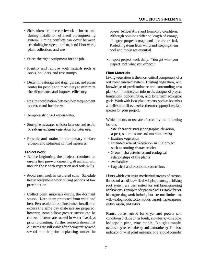
SOIL BIOENGINEERING
bull Create terraces on contour when slopes exceed 35 percent Dig these terraces 10 to 14 inches deep across slope face Spacing usually varies from 4 to 10 feet depending on conditions (fig 2) The objective is to accelerate establishment of plants by reducing slope angle and steepness between each terrace
bull Broadcast seed fertilizer and weed-free straw Make sure your seed is covered with at least 14 inch of soil Seed and fertilize as required by mix directions For example a mix may consist of 1 part seed (annual rye and forb mix) and 3 parts fertilizer (161616) Organic amendments in place of fertilizers also work well Work with local vegetation and soils specialists to determine desirable seed species and soil nutrient needs In addition determine if burying seed is critical for germination
bull Hand spreading of mulch is sufficient However machine application spreads materials more evenly and requires less mulch for full coverage As a result machine application may be more economical than hand distribution
bull In addition to mulching the site it is critical to protect areas from additional surface water flow specifically overland flow from roads Direct water flow away from the project area by constructing crossdrains across the road surface several feet prior to the project area Location and number of crossdrains needed will depend on several factors including road gradient and whether or not the road is outsloped or insloped above project area Crossdrains are cut approximately 6 inches deep across road surface to a vegetated stable point on the fillslope These hand-excavated drains are a temporary measure until heavy equipment is available to dig deeper water diversions An alternative to crossdrains or an additional measure to consider is to install drain rock and allow the water to move through the project area
Live staking Robbin Sotir amp Associates Live Staking Advantages Overtime a living root mat developes soil by reinforcing and binding soil particles together and by extracting excess soil moisture Appropriate technique for repair of small earth slips and slumps that usually have moist soils
Disadvantages Does not solve existing erosion problems (excluding benefits from associated mulch) live staking is not a short-term solution to slope instabilities
Tools needed Hand pruners and clippers untreated twine deadblow or rubber hammer burlap sacks (moistened and lined with wet leaves or mulch)
Procedure Vegetative cuttings are living materials and must be handled properly to avoid excess stress such as drying or exposure to heat They must be installed in moist soil and adequately covered with mulch Soil must be tamped to eliminate or minimize air pockets around buried stems
Installation is best accomplished in late fall at onset of plant dormancy in the winter as long as the ground is not frozen or in early spring before budding growth begins
Live staking involves insertion and tapping of live rootable vegetative cuttings (eg willow cottonwood
14
SOIL BIOENGINEERING
and red-osier dogwood) into the ground If correctly prepared and placed the live stake will root and grow
bull Live cuttings are usually 12 to 1 12 inches in diameter and 18 to 36 inches long Materials must have side branches cleanly removed and bark intact Young shoots 1 to 2 years of age work best Older and larger stems have a higher rate of mortality but can be successful with additional treatment eg bark scoring and rooting hormones
bull Cut basal end at an angle for easy insertion into the soil Cut top square (figure 1)
bull Best results are obtained when installation occurs the same day stakes are prepared however some believe greater success can be realized if stems are soaked in water 5 days prior to planting Further research shows that cut stems are still viable after being refrigerated several months prior to planting Although opinions differ on length of storage all agree proper storage and use are critical Protecting stems from wind and keeping them cool and moist are essential
bull Orient buds up
bull Tap live stake into the ground at right angles to the slope Installation may be started at any point on the slope face
bull Two-thirds to three-quarters of the length of the live stake should be installed into the ground and soil firmly packed around it after installation (figure 1) The more stem exposed to air the more moisture is lost This moisture is critical for root development
bull Install live stakes 2 to 3 feet apart using triangular spacing Density of installation should range from 2 to 4 live stakes per square yard
bull Be careful not to split stakes while tamping them into the ground Covering the stake with a 2 by 4-inch wood section will cushion the blows thus protecting the stake from splitting Trim damaged top area
bull Rebar can be used to make a pilot hole in firm soil Tamp the live stake into the ground with a deadblow (hammer filled with shot or sand) or rubber mallet
Figure 1ndashLive stake
14 to 13 ldquo Flat top
12 to 1-12 ldquo
18 to 36 ldquo
Angle
Bury 23 to
34 of stem
not to scale
15
SOIL BIOENGINEERING
Hand excavated terraces for erosion control blanket USDA Rolling out erosion control blanket USDA Forest Service Forest Service
Installation of Erosion Control Blanket Advantages Excellent for mitigating surface erosion The blanket offers immediate and uniform slope protection from rain and overland water flow if it is installed in full contact with the soil surface
Disadvantages Can be labor intensive and expensive Requires numerous wood stakes or livestems Too much grass within the blanket will lead to over competition for moisture sunlight and nutrients and may result in high tree and shrub mortality
Installation of erosion control blankets involves site preparation trenching application of grass andor forb seed mix and fertilizer and installation of fabric This technique is suitable for treating surface erosion areas especially fillslopes where there is a concentration of surface water runoff (figure 3)
Tools needed McLeod rake hand seeder 6-inch spikes and 2-inch pieces of rubber or fire hose hand prunners and clippers heavy duty scissors deadblow or rubber hammer
Procedure bull Round top edge of slope failure (figure 18) For
project success it is critical to address initiation point or chronic erosion source of the slope failure The common initiation point for these
failures is located at the upper boundary of the site For project success it is critical to remove and or round off slope overhang (figure 18)
bull Smooth all eroding areas such as rills or gullies In addition roughen entire site Do this by raking across and not downslope Raking downslope can lead to channeling water
bull Create a small berm on road edge (figure 2)
bull Excavate terraces 10 to 14 inches deep and 5 feet apart (figure 2)
bull Broadcast seed and fertilizer on treatment area as required by mix directions An example one seed mix may include 1 part annual rye and 3 parts 161616 fertilizer Organic amendments can be used in place of inorganic fertilizers
bull Roll out blanket parallel with road between trenches Fabric edges should lay evenly across bottom and top trenches Begin matting installation at bottom two trenches (figure 2)
bull Follow these directions for remaining rows The upper row of fabric should overlap the lower row Lay edge of top row of fabric into shallow terrace created while excavating the berm at road edge (figure 2)
16
SOIL BIOENGINEERING
bull To secure fabric into road edge nail 60D spikes through a hose piece washer If road surface is not too compacted use dead wood stakes instead of nails Nail or stake every 3 to 4 feet across top row of fabric at road edge (figure 2) Once nailed rake bermed soil back over matting edge Note Check with road manager to ensure maintenance activities will not require blading road edge at fabric site Road blading would lead to tearing out sections of the project If this is a major concern install upper edge of fabric a few 4 to 6 inches below the road edge
bull To secure fabric to slope face install live stakes into fabric across slope and through terraces
Optimum spacing of these stakes ranges from 2 to 3 feet Maximum spacing between stakes should not exceed 4 feet (figure 3)
bull Tamp live stakes in leaving 14 to13 of stem above ground and 34 to 23 below ground (figure 1) Trim stakes if more than 13 is exposed Average length of stake ranges from 18 to 36 inches Stakes should be flatcutontopand diagonalcuton bottom so they will be installed correctly and easily (figure 1) Remove top sections of stakes damaged during installation If you are not working in moist soil eg riparian area the willows will not survive In these cases it would be more cost effective to use wood stakes instead
CutslopeShallow terrace
6rdquo berm
Cutslope
Nail and washer 3rsquo to 4rsquo apart
Roadbed
Overlap matting on terraces
Terrace 10rdquo to 14rdquo deep
5rsquo ft
Matting
5rsquo ft
Roadbed
not to scale
Figure 2ndashInstallation of erosion control blanket
17
SOIL BIOENGINEERING
Roadbed Terraces
Side view
Terrace
Nails or stakes Roadbed
Nails or stakes
Terrace
not to scale
Live cribwall one month after construction USDA Forest Service
Figure 3ndashInstallation of erosion control mat
Construction of Live Cribwalls Advantages Appropriate at base of a cut or fillslope where a low wall or log may be required to stabilize toe of the slope and reduce slope steepness Useful where space is limited and a more vertical structure is required Provides immediate protection from erosion while established vegetation provides long term stability Aesthetically more pleasing and possibly less expensive compared to conventional gabion baskets
Disadvantages Not designed for or intended to resist large lateral earth stresses Depending on soil quality of cutslope may have to use commercial fill material Can be labor intensive and expensive to construct Can have high mortality if willow stems are not collected when dormant not cut and used the same day or mishandled in transfer
A live cribwall consists of a hollow box-like interlocking arrangement of untreated log or timber members The structure is filled with suitable backfill material and
18
SOIL BIOENGINEERING
Live cribwall during construction USDA Forest Service
layers of live branch cuttings such as willow or dogwood which root inside the crib structure and extend into the slope Cribwall should be tilted or battered back if constructed on a smooth evenly sloped surfaceOnce live cuttings root and become established subsequent vegetation gradually takes over the structural functions of wood members (figure 8) Coordinate with road manager prior to construction Often their primaryconcern is the structure will block water flow in the ditch line Make sure the design takes this concern into consideration
Basic design ideas are from Sotir and Gray 1982 and 1992 The following description and guide however includes several changes
Tools needed Chainsaw McLeod rake deadblow or rubber hammer 8 to 12 inch spikes or rebar shovels hand prunners and clippers
Procedure A Starting at lowest point of the slope excavate
loose material until a stable foundation is reached
B Place first course of 4 to 8 inch diameter logs or timbers at front and back of excavated foundation approximately 4 to 5 feet apart and parallel to the slope contour These are your main beams (figure 4)
C Lay 4 to 5 foot long and 4 to 8 inch diameter cross beams (either conifer or hardwood) across
main beams Spike or wire cross beams to main beams front and back (figure 5)
D Fill inside of main frame with soil Note Some gravel and rock can be used however willows will have more vigor if soil conditions are favorable If consequence of project failure is high it is critical to use commercial fill material
E Lay 5 foot long and 12 to 3 inch diameter trimmed live cut branches (3 to 6 inches apart depending on soil moisture) between cross beams and into cutbank On the bottom layer lay the basal ends of live cut branches under back main beam and on top of front main beam (figure 5 and figure 6) Note The purpose is to take full advantage of excess water at slope base If you do not have excess soil moisture conditions you do not have to lay butt ends of branches under back main beam Instead you can lay them directly over this beam
F Following ldquoArdquo and ldquoBrdquo start second layerThe onlydifference is set main beams back the width of bottom main beams and into cutbankThis allows cribwall to lean into cutbank and keeps fill material from falling out of front of cribwall (figure 7)
G Fill frame with soil
H Lay 4 to 5 foot long live cut branches on top of front and back main beams and between cross beams Lay these live branches approximately 3 inches apart (figure 5) Spacing of branches depends on availability of moisture and can range from side-by-side to 6 inches apart
I Continue constructing layers following ldquoErdquoldquoFrdquo and ldquoGrdquo until you reach specified height
J If needed construct wings or flanges to catch soil at structurersquos edges and to key in the structure to the slope face
19
main
ain b
SOIL BIOENGINEERING
K Cribwall should be tilted back if constructed on a smooth evenly sloped surface This can be accomplished by excavating the back of the stable foundation (closest to the slope) slightly deeper than the front to add stability to the structure (figure 8)
L May be constructed in a stair-stepped fashion with each successive layer of timbers set back 6 to 9 inches toward back cut slope face from previously installed course
Half Cribwall bull To insure minimum road width of 14 feet it
may be necessary to construct a half cribwall This is done by cutting cross beams width in half from 4 to 2 feet wide at base of cribwall (figure 7) and gradually increasing cribwall width by layer as desired cribwall height is being achieved (figure 7 and figure 8)
Toe Log Technique bull The toe log technique is a handy tool for very
small cutslope erosion features eg 10 feet high by 15 feet wide Place a 20 to 24 inch diameter log along the base of the erosion site Lay 5 foot long and 12 to 1 inch diameter live cut branches (side-by-side to 6 inches apart depending on soil moisture) on top of the log and into cutbank (figure 7) The purpose is to take full advantage of excess water at slope base Place soil behind the log with soils from the slope face Toe logging is a quick and effective tool in stabilizing base of slopes However it is only effective when sites are small and only slightly over steepened It is very important to use the right size log for existing slope condition
When constructing a live cribwall half cribwall or toe log the initiation point of the slope failure must be addressed The common initiation point or source of chronic erosion for these failures is located at the upper boundary of the site For project success it is critical to remove or round off slope overhang (figure 18)
Rear beam
Front m eam
Cutslope
Edge of cutbank
Road
For half cribwall
Ditch
20
not to scale
4-8 diameter
Figure 4ndashLive cribwall construction
20
SOIL BIOENGINEERING
Rear main beam
Front main beam
Cutslope
Edge of cutbank
Road
3 apart
Ditch
not to scale
4 to 8
20
5 long
8 to 12spike
12 to 3 diameter 5 in length
4-8 diameter
Figure 5ndashLive cribwall construction
Crossbeam
Back mainbeam
Spikes Ditch
Roadbed
Cutslope
Willow on top of front main beam
Willow under rear main beam
Existing roadbed
not to scale
Figure 6ndashLive cribwall construction
21
SOIL BIOENGINEERING
3rsquo to 5rsquo
Constructed into slope
minimum of 6rsquo 8 to 12rdquo
Ditch
Roadbed
Half cribwall
1-12 to 3rdquo 4rsquo diameter
Ditch
Roadbed Ditched
Toe log 20-24rdquo diameter 2rsquo
Figure 7ndashLive cribwall-stepped full half and toelog construction
Evacuated cutslope
New slope
Roots
5rsquo to 6rsquo
Soil
Ditch Roots
Figure 8ndashLive cribwall battered construction
22
SOIL BIOENGINEERING
Live facines illustration Kraebel Live Fascine Advantages Immediately reduces surface erosion or rilling Suited to steep rocky slopes where digging is difficult Capable of trapping and holding soil on the slope face thus reducing a long slope into a series of shorter steps Can also be used to manage mild gully erosion and can serve as slope drains when bundles are angled Best suited for moist soil conditions Note Where soil moisture is not sufficient for supporting live materials fascines can also be constructed of plant stems not intended for rooting The bundle still traps and holds sediments and reduces slope length and steepness between terraces Plant vegetation on andor between the terraces As inall projects living recovery is dependent on successfully establishing the vegetation
Disadvantages On steep or long slope lengths high runoff velocities can undermine live fascines near drainage channels Significant quantity of plant material is required and can dry out if not properly installed Best suited for riparian moist soil conditions Otherwise high plant mortality could occur
Live fascines (Kraebel1936 and Sotir and Gray1982 and 1996) also referred to as contour or willow wattling are long bundles of branch cuttings bound together into sausage like structures (figure 9)
Tools needed Hand pruners and clippers untreated twine (not hemp) pulaski or hazel hoe deadblow or rubber mallet McLeod rake dead plant materials
Procedure bull Excavate 10 to 14 inch deep terraces along slope
contour and the full width of treatment area Spacing of terraces averages between 5 to 7 feet with a goal of 11 slope Terrace placement is a function of slope and should be calculated Terrace excavation and live fascine installation should progress from base of project up to slope crest
bull Bundle willow branches Other species such as red-osier dogwood or snowberry can be used For best results cut and use plant materials same day (See comments in Live Staking about collection and timing of installation) Butt ends and top ends are usually laid alternately until a bundle has been created which looks like an 8 to10 inch wide sausage Plant materials should be about 12 to 5 inches in diameter and about 4 to 8 feet in length (figure 9) Bundles are then tied together using up to 20 percent dead material and bound with untreated lengths of twine Note Use of up to 20 percent dead materials retains structural properties of live fascine and bundle still has enough live material to grow
bull Lay bundle across terrace splice together ends of each (figure 9) and do not overlap Bundles should be 14 to 13 exposed
Live facine installation USDA Forest Service
23
SOIL BIOENGINEERING
Live facine installationndashangled Robbin Sotir amp Associates
bull Next live stake the downslope side of terraces at middle and overlap points to hold live fascines in the terrace Be sure to splice ends of bundles In addition place wood stakes through live facines every two feet Wood stakes should be driven directly through bundle center (figure 9) Live willow and wood stakes should be 1 to 3 inches in diameter and 2 to 3 feet long Stakes should be flat cut on top and diagonally cut on bottom to ensure appropriate and easy installation Remove top section of live stakes damaged during installation
bull Stand in completed terrace and begin excavation of second terrace This process will allow soil from second terrace to cover first row Walk on wattles to compact and to gain good soil fascine contact
bull If available water fascine to work soil into the bundle for increased soil contact and decreased desiccation
bull Move upslope to next terrace alignment and repeat process (figure 9)
1
2
3
Untreated Twine Ties
Stems 12 to 1-12 diameter 8 to 10 diameter
4 to 8 length not to scale
Live facine Wood stake
Live stake
Spacing averages 5rsquo to 7rsquo
face measurement
Figure 9ndashLive fascines
24
SOIL BIOENGINEERING
Brushlayering Advantages Breaks up slope length into a series of shorter slopes separated by rows of brushlayer Reinforces soil as roots develop adding resistance to sliding or shear displacement Reinforces soil with unrooted branch stems Provides slope stability and allows vegetative cover to become established Traps debris on slope Aids infiltration on dry sites Dries excessively wet sites
Disadvantages Recommended on slopes up to 21 in steepness and not to exceed 15 feet in vertical height Labor intensive
Brushlayering (Sotir and Gray 1982 and 1992) consists of placing live branch cuttings in small terraces excavated into the slopeTerraces can range from 2 to 3 feet wide This technique is similar to live fascine systems because both involve cutting and placement of live branch cuttings on slopes The two techniques differ in the orientation of the branches and depth they are placed in the slope In brushlayering cuttings are oriented perpendicular to slope contour (figure 10) This placement is more effective fromthe pointof view of earth reinforcement and mass shallow stability of the slope
Tools needed Hand pruners and clippers untreated twine (not hemp) pulaski or hazel hoe shovel deadblow or rubber hammer McLeod rake
Digging terraces for brushlayer installation Robbin Sotir amp Associates Brushlayer installation Robbin Sotir amp Associates
Procedure bull Begin project at base of treatment area Excavate
terrace so that approximately 14 of average brush length extends beyond slope face Do not over excavate This technique can trigger soil movements during installation It is important therefore to perform installation in phases and to avoid excavating more area than is necessary to install plant materials (figure 10)
bull Lay an appropriate amount (ie 20 to 25 stems per yard) of single or multiple mix of live brush species along trench sidewall Length of stems can vary from 3 to 4 feet and diameter 12 to 3 inches (figure 10)
bull Stand in completed terrace and begin excavation of second terrace This process allows soil from second terrace above to cover first brushlayer row Compact and slightly mound soil behind brushlayers
bull Move upslope to next trench alignment and repeat process (figure 10)
Brushlayers modified with log terracing installing a short small log (figure 10) can modify brushlayers The log provides additional support to the brushlayer reduces slope angle and serves as a small terrace to ldquocatchrdquo rolling rocks rather than allowing them to roll down the slope and damage vegetation
25
Slope
Installation fall line
direction
SOIL BIOENGINEERING
Brushlayering just after installation Robbin Brushlayering 3 months after installation Sotir amp Associates Robbin Sotir amp Associates
Spacing averages 5-7
Stems 1 14 to 2
diameter
2
3
Spacing 4 to 10
Plant shrubs and trees throughout slope face
To reduce slope angle Live branch cuttings
Log (4 to 6 diameter)
Brushlayer
Length = 2 to 6
Stake
Brushlayer with log terrace
not to scale
Figure 10ndashBrushlayering and brushlayering w log terrace
26
SOIL BIOENGINEERING
Willow fencing with brushlayering USDA Forest Service
Willow Fencing Modified with Brushlayering Advantages These structures reduce slope angle providing a stable platform for vegetation to establish Willow fences trap rolling rocks and sliding debris and protects vegetation growing lower on the slope Willow fences provide support for small shallow translational or rotational failures Sites where fine textured soils can provide ample summer moisture or where seepage of groundwater provides moisture are suitable for willowbrushlayering fence installations These structures can also be constructed on dryer sites however expect high willow mortality In these situations the willow shelf is considered a temporary planting platform It is important therefore to establish deeper rooting shrubs and trees within the shelf When the structure begins to decay root systems of other plants will serve as the permanent feature
Disadvantages Significant quantity of plant material is required Moist site conditions are required for the fence to sprout and grow
Willow fencing with brushlayering is essentially a willow fence supported on a short brushlayer Specifically it is a short retaining wall built of living cuttings with a brushlayer base (figure 11) Willow fencing can also be used without base brushlayering (Polster 1998)
Tools needed Hand pruners and clippers pulaski or hazel hoe McLeod rake deadblow or rubber hammer wood stakes or rebar
Procedure Brushlayering bull Begin project at base of treatment area Excavate
16 to 20 inch deep trenches along slope contour and for full width of treatment area Spacing of trenches averages between 5 to 8 feet full measurement depending on site conditions This technique can cause additional erosion during installation therefore it is important to construct project in phases and to avoid excavating more area than is necessary to install plant materials (figure 11)
12 to 2 diameter
Willow fencing
18 to 36 long stakes 2 to 3 diameter
Brushlayer
18 to 36 long cuttings 1 2 to 2 diameter
Figure 11ndashWillow fencing modified with brushlayering
27
SOIL BIOENGINEERING
bull Lay live brush stems along base of trench Length of stems average 16 inches in length and diameter of 12 to 2 inches Approximately 14 of average brush length should extend beyond slope face (figure 10)
Willow fencing bull Install supporting 18 to 36 inch long wood
stakes cuttings or rebar Average diameter of stakes ranges from 2 to 3 inches
bull Place a few shrub cuttings 18 to 36 inch long and 12 to 2-inch diameter cuttings behind these supports
bull Place enough soil behind these supports to hold the shrub cuttings in place
bull Stand in the trench and begin excavation of second row This process will allow soil from second trench to cover first willow fencing brushlayer row
bull Compact and slightly mound soil on brushlayer and behind willow fence
bull As more soil is added add additional cuttings until the final height of the fence is achieved A goal should be to construct a 21 slope or less between the top of the willow fence and the bottom of the one above
bull Move upslope to next trench alignment and repeat process (figure 11)
Branchpacking just after installation Robbin Sotir amp Associates
Branchpacking Advantages As plant tops grow branchpacking system becomes increasingly effective in retarding runoff and reducing surface erosion Trapped sediment refills localized slumps orholeswhile roots spreadthroughout the backfill and surrounding earth to form a unified mass (figure 12)
Disadvantage Not effective in slump areas greater than 4 feet deep or 5 feet wide
Branchpacking (Sotir and Gray 1992) consists of alternating layers of livebranch cuttings and compacted backfill to repair small localized slumps and holes (figure 12)
Tools needed Hand pruners and clippers deadblow or rubber hammer untreated twine McLeod rake shovel wood stakes
Branchpacking just after installation Robbin Sotir amp Associates
28
SOIL BIOENGINEERING
Branchpacking post installation Robbin Sotir amp Associates
Procedure bull Starting at lowest point drive wooden stakes
vertically 3 to 4 feet into the ground Set them 1- to 1 12 -feet apart Wooden stakes should be 5 to 8 feet long and made from 3-to-4 inch diameter poles or 2 by 4 lumber depending upon depth of particular slump or hole
bull Place a layer of live cut branches 4 to 6 inches thick in bottom of hole between vertical stakes and perpendicular to the slope face (figure 12) Crisscross branches with growing tips generally oriented toward slope face Some basal ends of branches should touch the back of the slope
bull Install subsequent layers with basal ends lower than the growing tips of the branches This is to insure developing root systems will be located at water collection points on the slope
bull Each layer of branches must be followed by a layer of compacted soil to ensure soil contact with branch cuttings
bull Final installation should match existing slope Branches should protrude only slightly from the filled face
bull The soil should be moist or moistened to insure live branches do not dry out
1 to 1-12
Live branch cuttings 14 to 2 diameter
Compact fill material
Wooden stakes 5 to 8 long 2 x 4 lumber driven 3 to 4 into undisturbed soil
4 to 6 inch layer of live branch cuttings laid criss cross and
touching back of hole
Live branch cuttings should protrude slightly from
backfill area
Several weeks or months later
spacing not to scale
Figure 12ndashBranchpacking
29
SOIL BIOENGINEERING
3 to 4 inch layer of live branch cuttings laid in crisscross and touching undisturbed soil on gully bed
Several weeks later
Live branch cuttings 1 to 2 in diameter
Compacted fill material 6 to 8 layer
Gully bed
Figure 13ndashLive gully repair
Live Gully Repair Advantages Offers immediate reinforcement to compacted soil reduces velocity of concentrated flow of water and provides a filter barrier to reduce rill and gully erosion
Disadvantages Limited to rills and gullies which are a maximum of 2-feet wide 1-foot deep and 15- feet long
Live gully repair (Sotir and Gray 1992) utilizes alternating layers of live branch cuttings and compacted soil to repair small rills and gullies Similar to branchpacking this method is more appropriate for repair of rills and gullies
Tools needed Hand pruners and clippers shovel McLeod rake untreated twine
Procedure bull Starting at lowest point of the slope place a 3shy
to 4-inch thick layer of live cut branches at lowest end of the rill or gully and perpendicular to the slope (figure 13)
bull Cover with 6-to 8-inch layer of soil
bull Install live cut branches in a crisscross fashion Orient growing tips toward slope face with basal ends lower than growing tips
bull Follow each layer of branches with a layer of compacted soil to ensure soil contact with live branch cuttings
30
SOIL BIOENGINEERING
Figure 14ndashVegetated geotextile
Vegetated Geotextile Advantages Retards rill and gully erosion stabilizes fill banks Is less expensive than other retaining walls such as gabion or Hilfiker baskets
Disadvantage Can be expensive if heavy equipment required
Synthetic or organic geotextile wrapped around lifts of soil with a mix of live branches placed between layers There are numerous opportunites of blending geotechnical-engineered systems with soil bioengineering The following is one example
Tools needed Backhoe geotextile hand pruners and clippers McLeod rake shovel untreated twine
Procedure bull Excavate lower edge of slope break and bench
backcut Compact the soil layer Note Structural integrity is dependent on compacted soil layers Even with mechanized firming soils support live cuttings
bull Lay first layer of geotextile down into the bench
bull Fill lowest lift with gravel fold back and stake securely
bull Fill subsequent layers with soil and layers of live cut branches (figure 10) and alternate with lifts (figure 14) Each layer must be compacted
bull The structure can be built with a vertical face or stair-stepped and sloped back into the hillside
31
SOIL BIOENGINEERING
Installation - cutslope stabilzation with log terracing USDA Forest Service
Log Terracing Advantages Logs create terraces reducing length and steepness of slope provides stable areas for establishment of other vegetation such as trees and shrubs
Disadvantages Labor intensive and with potential safety hazards
Tools needed Chainsaw PV pole blocks and cable power winch shackles and chokers pulaski Mcleod and shovel wood stakes hand pruner and clippers traffic control signs
Procedure bull The technique utilizes alternating terraced logs
to stop surface erosion on eroding slopes Stopping the erosion is critical for successful revegetation efforts Specifically log terracing shortens slope length and gradient between each structure providing stable planting areas throughout most of the slope face (figure 15)
bull Prior to beginning a log terracing project place traffic control signs several hundred feet on both sides of your project area Then climb slope to locate and remove potential safety hazards These hazards include loose tree root wads unstable rocks and boulders This inspection will also provide a different visual
perspective of the site This ldquotop-downrdquo viewpoint is usually the best place to formulate your project design
bull Begin log terracing at the base of the slope and work your way uphill This should prevent undercutting of any terrace or log you place above It also provides a stable and secure footing area for project work
bull Log terracing consists primarily of 3 main steps These steps include moving installing and anchoring logs to specified points on an eroding hillside
Moving bull Try not to cause any additional erosion or
damage log terraces you have already excavated This can be accomplished by setting up a skyline or carefully using a straight dragline with block and cable
Installation bull Use a minimum of 12-inch diameter logs
Sixteen or 20-inch diameter logs work best The most common error in log terracing is using logs that are too small in diameter
bull Use existing slope features such as tree stumps rock outcroppings or natural slope benches to secure one or both ends of the logs These natural features make project work easier safer and work better than stakes or rebar for keeping the log in place on the slope
bull Excavate terraces 13 the width of the log diameter deep and for full length of the log With rope (or cable) blocks and winch place the logs into position (figure 16)
Anchoring bull Depending on site conditions attempt to space
log terraces 10 to 20 feet apart
32
SOIL BIOENGINEERING
bull Anchor logs into the slope using 3-to 5-inch should be inserted into the ground Bend over diameter wood stakes or 34 inch rebar any excess rebar
bull Stake length should be 4 times the diameter of the log A 12-inch diameter log for example would require 48-inch long stakes and a 16shyinch diameter log 64-inch long stakes
bull Once in place drive stakes vertically into slope just below the log Two thirds of the stake should be driven into the ground These stakes should be spaced every 4 feet across the length of the log (figure 17) Another recommended technique is to drill holes through the log and anchor with rebar Two thirds of total length
bull When utilizing tree stumps and rock outcroppings for anchor points gaps may occur between log and soil surface This gap must be filled To do so excavate a trench uphill from the log and place a smaller log flush with the log structure (figure 17)
bull There are many possible patterns for log terracing The following 3 have proved useful for stabilization efforts (figure 15) Whatever pattern utilized it is absolutely critical no gaps exist between the log and soil surface
Erosion site Erosion site Erosion site
Retaining structure Retaining structure Retaining structure
15-20
15-20
Shortened slope distance 50 failure
width
Rock
20
Treestump
Staggered Pattern Ladder Pattern Building Block Pattern
not to scale
Figure 15ndashLog terrace installation
33
SOIL BIOENGINEERING
Staggered Using logs with lengths greater than 50 percent of the width of the erosion site These logs should overlap each other and be anchored into stable soils on either side of the failure site
Ladder Logs extend across full width of erosion site and should be anchored into stable soils on either side of failure site
Building block This method best mimics what happens naturally on an eroding slope Begin the project at the slope base This area is stable and will provide a secure base to build off of as you work your way up slope There is no set pattern Design and log placement pattern will evolve as the project progresses Be creative
bull Once the slope has been stabilized with log terracing it is critical to address the upper portion of the slope failure This area is often referred to as the slope overhang Addressing this area is critical since it is the source of the surface erosion Without removing this erosion source project success is unlikely Cut away the overhang so slope angle will allow seed to germinate and plants to establish Try to angle the slope to blend with the new slope gradient created with log terracing Often this will require a cut 5 to 6 feet upslope This is the most difficult portion of a log terracing project and will often result in removing vegetation This vegetation however can be transplanted to other areas on the slope
34
SOIL BIOENGINEERING
Use of existing slope features
Stump
Rock
Front view trench construction
Trench
Place log 13 of diameter deep
Slope
Place log 13 of diameter deep
Trench construction side view
Stakes
not to scale
Figure 16ndashLog terrace construction
Formula A 12 diameter log needs 48 long stakes
Trench
Stake 13 above
Stake 23 below
Stakes
Front view
Erosion site
Log
Cutslope
Roadbed
Vertical placement
Side view
Erosion site
Stake 13 above ground
Stake 23 below ground
Ground level
Gap
Ground level
Filler log
not to scale
Figure 17ndashAnchoring and filling gaps
35
SOIL BIOENGINEERING
Roadbed Ditch
Cutslope
Fill slope
Slope overhang
Slope overhang
Area to remove
Area to remove
not to scale
Figure 18ndashRemoval of slope overhang
36
SOIL BIOENGINEERING
Bender Board Fencing Advantages These structures reduce slope angle providing a stable platform for vegetation to establish Like willow fencing bender board structures trap rolling rocks and sliding debris and protects vegetation growing lower on the slope Bender board fences provide support for small translational or rotational failures
Dry sites where soils receive very little precipitation this type of structure The bender board shelf is considered a temporary planting platform It is important therefore to establish deeper rooting shrubs and trees within the shelves When the structures begins to decay root systems of other plants will serve as the permanent feature
Disadvantage Significant quantity of plant material is required
Redwood or cedar bender board fencing is essentially a fence supported on a short layer of shrub or tree stems Specifically it is a short retaining wall built of redwood or cedar bender fencing with a stem layered base
Tools needed Hand pruners and clippers pulaski or hazel hoe McLeod rake deadblow or rubber hammer wood stakes
Procedure Stem Layered Base bull Begin project at base of treatment area Excavate a
24-inch deep terrace along slope contour and for full width of treatment area The back of the terrace should be dug with an approximate 70 degree angle To allow ample planting platforms space terraces about 5 feet apart
bull Lay 2 feet 6-inch long stems and 2 feet 6-inch long wood stakes (5050 mix) 2-inches apart and for full length of terrace Diameter can range from 12 to 2-inches Approximatly 6-inches will extend beyond slope face
Bender board Fencing bull Drive supporting 4 foot 6-inch (2 by 2) long stakes
2 to 3 feet into ground spaced 1 foot apart and perpendicular to the slope Rebar may be used instead of wooden stakes
bull Weave 10 foot long bender boards through these stakes until the wall reaches a height of 2 feet Once complete the bender board fence wall should be at a 15 degree angle to the slope Note As shown in photo some bender board are too brittle to weave
bull Once the wall frame is constructed carefully rake enough soil into the terrace to cover the stem layered base
37
SOIL BIOENGINEERING
bull Stand in terrace and begin excavation of second bull Move upslope to next terrace alignment and row This process will allow soil into the terrace repeat process to cover the stem layered base
bull A goal should be to construct a 21 slope or less between the top of the bender board fence wall and the bottom of the one above
10 foot long bender boards 14 thick 3-12 wide
2-6 long stakes spaced 3 apart
2 high seven bender boards
2 wide terraces spaced 5 apart
not to scale
4-6 post buried 2-3
Figure 19ndashBender board fencing
38
SOIL BIOENGINEERING
REFERENCES CITED
Bach David H and MacAskill IA 1984 Vegetation and Landscape Engineering Granada London
Bennett Francis W 1975 Methods of Quickly Vegetating Soils of Low Productivity Construction Activities US Environmental Protection Agency Washington DC
Brosius Myra 1985 ldquoThe Restoration of an Urban Stream Using Geomorphic Relationships and Biotechnical Streambank Stabilizationrdquo Athens GA University of Georgia Thesis
Chandler RJ 1991 Slope Stability Engineering Institution of Civil Engineers Thomas Telford Publishing Company
Chatwin S D Howes and D Swantson 1994 A Guide for Management of Landslide Prone Terrain in the Pacific Northwest Second edition Ministry of Forests Crown Publications Victoria BC
Christensen M and J Jacobovitch 1992 Revegetation Projects Everything You Wanted to Know About Live Staking Unpublished report for King County Dept of Public Works Surface Water Management Div Seattle WA
Coppin NJ and IG Richards 1990 Use of Vegetation in Civil Engineering Butterworths London England
Coppin Nick J and R Stiles 1989 The Use of Vegetation in Slope Stabilization Landscape Design with Plants Second Edition ed by Brian Clouston Boca Raton Florida CRC Press 212-234
Edlin HL 1949 Woodland Crafts in Britain BT London Batsford Ltd London
Finney Kevin P 1993 BioEngineering Solutions A Tool for Education Eugene OR University of Oregon Thesis
Finney K 1993 History of Soil Bioengineering Eugene OR Masters Thesis University of Oregon Thesis
Gray DR and AT Leiser 1982 Biotechnical Slope Protection and Erosion Control New YorkVan Nostrand Reinhold Company New York
Gray DH Leiser T Andrew and C A White 1980 Combined Vegetative Structural Slope Stabilization Civil Engineering 50(1)82-85
Gray D R and Sotir RB 1996 Biotechnical and Soil Bioengineering Slope Stabilization John Wiley and Sons Inc
Greenway DR 1987 Vegetation and Slope Stability In Slope Stability John Wiley and Sons Ltd Chapter 6
41
SOIL BIOENGINEERING
Johnson AW and JM Stypula eds 1993 Guidelines for Bank Stabilization Projects In the Rivetine Environments of King County County Department of Public Works Surface Water Management Division Seattle WA
Kraebel CJ 1936 Erosion Control on Mountain Roads USDA Circular No 380 Washington DC USDA
Kraebel CJ 1933 Willow Cuttings for Erosion Control Technical Note No 1 Berkely California USDA California Forest Experiment Station
Larson FE and WE Guse 1981 Propagating Deciduous and Evergreen Shrubs Trees and Vines with Stem Cuttings Pacific Northwest Coop Ext Pub PNW152
Leiser Andrew T J J Nussbaum Kay Burgess Paul Jack and W Thornhill 1974 Revegetation of Disturbed Soils in the Tahoe Basin California Department of Transportation Sacramento California
Lewis EA and LW Ogg 1993 Soil Bioengineering Project Descriptions Unpublished report for Olympic National Forest Hood Canal Hanger District
Leys Emil 1978 Wilhelm Hassenteufel 80 Years Old Garten und Landschaft in China Vol 4 Part 3 Cambridge The University Press
Maleike R and RL Hummel 1988 Planting Landscape Plants Wash State Univ Coop Ext Pub EB1505
Polster Environmental Services 1998 Soil Bioengineering for Forest Land Reclamation and Stabilization British Columbia Ministry of Forests
Robbin B Sotir amp Associates A Brief History of Soil Bioengineering Unpublished and undated manuscript
Schiechtl Hugo 1980 Bioengineering For Land Reclamation and Conservation Edmonton Canada The University of Alberta Press
Schiechtl H M and R Stern 1997 Ground Bioengineering Techniques for Slope Protection and Erosion Control Blackwell Science Publications ISBN 0-632-04061-0
Sotir RB and DH Gray 1992 Soil Bioengineering for Upland Slope Protection and Erosion Reduction Engineering Field Handbook Soil Conservation Service Chapter 18
Stiles Richard (172) 57-61 1988 Engineering with Vegetation Landscape Design (172) 57-61
Stiles Richard1991 Re-inventing the Wheel Landscape Design (203)
42
SOIL BIOENGINEERING
Weaver WE and MA Madej 1981 Erosion Control Techniques Used in Redwood National Park In Davies TRH and AJ Pearce eds Erosion and Sediment Transport in Pacific Rim Steeplands Washington DC Intrsquol Assoc Hydrological Sciences 640-654 IAHS-AISH Pub 132
Westmacott Richard 1985 The Rediscovered Arts of Twilling and Wattling Landscape Architecture 75(4)95-98
White Charles A and AL Frank S 1978 Demonstration of Erosion and Sediment Control Technology Lake Tahoe Region of California EPA-6002-78-208 Municipal Environmental Research Laboratory Office of Research and Development US Environmental Protection Agency Cincinnati Ohio
Ziemer RR 1981 Roots and the Stability of Forested Slopes In Davies TRH and AJ Pearce eds Erosion and Sediment Transport in Pacific Rim Steeplands
43
SOIL BIOENGINEERING
About the Authorhellip
Lisa Lewis graduated in 1987 from Fort Valley State University Fort Valley Georgia with a Bachelor of Science degree in Soil and Plant Sciences Lisa began her career with the Forest Service in August 1987 on the Hood Canal Ranger District She continued her career in the Pacific Northwest and since 1998 she has been a soil scientist with the National Riparian Service Team (NRST) As a member of the NRST Lisa provides training and technology transfer consulting and advisory services and program review for riparian restoration nationwide She specializes in road management issues and soil bioengineering techniques
Library Card
Lewis Lisa 2000 Soil bioengineeringmdashan alternative to roadside managementmdasha practical guide Technical Report 0077-1801-SDTDC San Dimas CA US Department of Agriculture Forest Service San Dimas Technology and Development Center 44 p
This publication provides field personnel with the basic merits of soil bioengineering concepts and gives examples of several techniques especially effective in stabilizing and revegetating upland roadside environments The information provided in this document is intended to stimulate additional interest for the reader to seek out and use these and other soil bioengineering applications
Soil bioengineering is the use of live plant materials and flexible engineering techniques to alleviate environmental problems such as destabilized and eroding slopes Unlike other technologies in which plants are chiefly an aesthetic component of the project in soil bioengineering systems plants are an important structural component
Keywords Soil bioengineering road management road maintenance restoration erosion native plant materials revegetation
Additional single copies of this document may be ordered from
USDA Forest Service San Dimas Technology and Development Center
ATTN Richard Martinez 444 E Bonita Avenue San Dimas CA 91773
Phone (909) 599-1267 x201 Fax (909) 592-2309
E-Mail rmartinezwo_sdtdcfsfedus FSNotes Richard MartinezWOUSDAFS
For additional technical information contact Lisa Lewis at the following address
USDA Forest Service National Riparian Service Team
3050 NE 3rd Street PO Box 550
Prineville OR 98854 Phone (541) 416-6788
E-Mail l3Lewisorblmgov
An electronic copy of this document is available on the Forest Servicersquos FSWeb
Intranet at httpfswebsdtdcwofsfedus
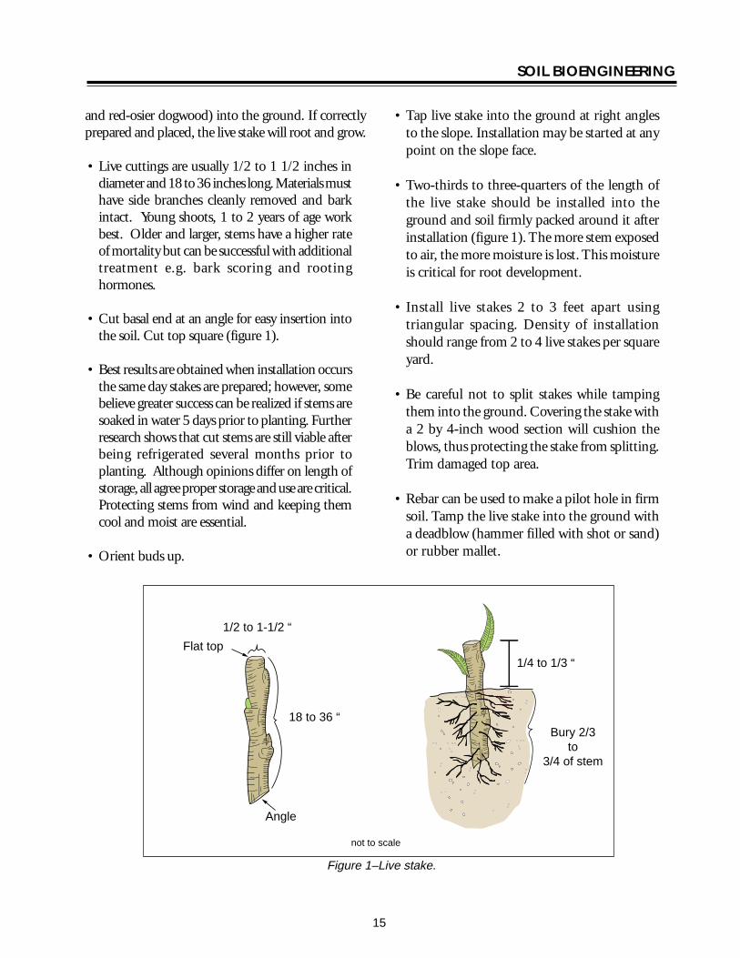
SOIL BIOENGINEERING
Live cribwall during construction USDA Forest Service
layers of live branch cuttings such as willow or dogwood which root inside the crib structure and extend into the slope Cribwall should be tilted or battered back if constructed on a smooth evenly sloped surfaceOnce live cuttings root and become established subsequent vegetation gradually takes over the structural functions of wood members (figure 8) Coordinate with road manager prior to construction Often their primaryconcern is the structure will block water flow in the ditch line Make sure the design takes this concern into consideration
Basic design ideas are from Sotir and Gray 1982 and 1992 The following description and guide however includes several changes
Tools needed Chainsaw McLeod rake deadblow or rubber hammer 8 to 12 inch spikes or rebar shovels hand prunners and clippers
Procedure A Starting at lowest point of the slope excavate
loose material until a stable foundation is reached
B Place first course of 4 to 8 inch diameter logs or timbers at front and back of excavated foundation approximately 4 to 5 feet apart and parallel to the slope contour These are your main beams (figure 4)
C Lay 4 to 5 foot long and 4 to 8 inch diameter cross beams (either conifer or hardwood) across
main beams Spike or wire cross beams to main beams front and back (figure 5)
D Fill inside of main frame with soil Note Some gravel and rock can be used however willows will have more vigor if soil conditions are favorable If consequence of project failure is high it is critical to use commercial fill material
E Lay 5 foot long and 12 to 3 inch diameter trimmed live cut branches (3 to 6 inches apart depending on soil moisture) between cross beams and into cutbank On the bottom layer lay the basal ends of live cut branches under back main beam and on top of front main beam (figure 5 and figure 6) Note The purpose is to take full advantage of excess water at slope base If you do not have excess soil moisture conditions you do not have to lay butt ends of branches under back main beam Instead you can lay them directly over this beam
F Following ldquoArdquo and ldquoBrdquo start second layerThe onlydifference is set main beams back the width of bottom main beams and into cutbankThis allows cribwall to lean into cutbank and keeps fill material from falling out of front of cribwall (figure 7)
G Fill frame with soil
H Lay 4 to 5 foot long live cut branches on top of front and back main beams and between cross beams Lay these live branches approximately 3 inches apart (figure 5) Spacing of branches depends on availability of moisture and can range from side-by-side to 6 inches apart
I Continue constructing layers following ldquoErdquoldquoFrdquo and ldquoGrdquo until you reach specified height
J If needed construct wings or flanges to catch soil at structurersquos edges and to key in the structure to the slope face
19
main
ain b
SOIL BIOENGINEERING
K Cribwall should be tilted back if constructed on a smooth evenly sloped surface This can be accomplished by excavating the back of the stable foundation (closest to the slope) slightly deeper than the front to add stability to the structure (figure 8)
L May be constructed in a stair-stepped fashion with each successive layer of timbers set back 6 to 9 inches toward back cut slope face from previously installed course
Half Cribwall bull To insure minimum road width of 14 feet it
may be necessary to construct a half cribwall This is done by cutting cross beams width in half from 4 to 2 feet wide at base of cribwall (figure 7) and gradually increasing cribwall width by layer as desired cribwall height is being achieved (figure 7 and figure 8)
Toe Log Technique bull The toe log technique is a handy tool for very
small cutslope erosion features eg 10 feet high by 15 feet wide Place a 20 to 24 inch diameter log along the base of the erosion site Lay 5 foot long and 12 to 1 inch diameter live cut branches (side-by-side to 6 inches apart depending on soil moisture) on top of the log and into cutbank (figure 7) The purpose is to take full advantage of excess water at slope base Place soil behind the log with soils from the slope face Toe logging is a quick and effective tool in stabilizing base of slopes However it is only effective when sites are small and only slightly over steepened It is very important to use the right size log for existing slope condition
When constructing a live cribwall half cribwall or toe log the initiation point of the slope failure must be addressed The common initiation point or source of chronic erosion for these failures is located at the upper boundary of the site For project success it is critical to remove or round off slope overhang (figure 18)
Rear beam
Front m eam
Cutslope
Edge of cutbank
Road
For half cribwall
Ditch
20
not to scale
4-8 diameter
Figure 4ndashLive cribwall construction
20
SOIL BIOENGINEERING
Rear main beam
Front main beam
Cutslope
Edge of cutbank
Road
3 apart
Ditch
not to scale
4 to 8
20
5 long
8 to 12spike
12 to 3 diameter 5 in length
4-8 diameter
Figure 5ndashLive cribwall construction
Crossbeam
Back mainbeam
Spikes Ditch
Roadbed
Cutslope
Willow on top of front main beam
Willow under rear main beam
Existing roadbed
not to scale
Figure 6ndashLive cribwall construction
21
SOIL BIOENGINEERING
3rsquo to 5rsquo
Constructed into slope
minimum of 6rsquo 8 to 12rdquo
Ditch
Roadbed
Half cribwall
1-12 to 3rdquo 4rsquo diameter
Ditch
Roadbed Ditched
Toe log 20-24rdquo diameter 2rsquo
Figure 7ndashLive cribwall-stepped full half and toelog construction
Evacuated cutslope
New slope
Roots
5rsquo to 6rsquo
Soil
Ditch Roots
Figure 8ndashLive cribwall battered construction
22
SOIL BIOENGINEERING
Live facines illustration Kraebel Live Fascine Advantages Immediately reduces surface erosion or rilling Suited to steep rocky slopes where digging is difficult Capable of trapping and holding soil on the slope face thus reducing a long slope into a series of shorter steps Can also be used to manage mild gully erosion and can serve as slope drains when bundles are angled Best suited for moist soil conditions Note Where soil moisture is not sufficient for supporting live materials fascines can also be constructed of plant stems not intended for rooting The bundle still traps and holds sediments and reduces slope length and steepness between terraces Plant vegetation on andor between the terraces As inall projects living recovery is dependent on successfully establishing the vegetation
Disadvantages On steep or long slope lengths high runoff velocities can undermine live fascines near drainage channels Significant quantity of plant material is required and can dry out if not properly installed Best suited for riparian moist soil conditions Otherwise high plant mortality could occur
Live fascines (Kraebel1936 and Sotir and Gray1982 and 1996) also referred to as contour or willow wattling are long bundles of branch cuttings bound together into sausage like structures (figure 9)
Tools needed Hand pruners and clippers untreated twine (not hemp) pulaski or hazel hoe deadblow or rubber mallet McLeod rake dead plant materials
Procedure bull Excavate 10 to 14 inch deep terraces along slope
contour and the full width of treatment area Spacing of terraces averages between 5 to 7 feet with a goal of 11 slope Terrace placement is a function of slope and should be calculated Terrace excavation and live fascine installation should progress from base of project up to slope crest
bull Bundle willow branches Other species such as red-osier dogwood or snowberry can be used For best results cut and use plant materials same day (See comments in Live Staking about collection and timing of installation) Butt ends and top ends are usually laid alternately until a bundle has been created which looks like an 8 to10 inch wide sausage Plant materials should be about 12 to 5 inches in diameter and about 4 to 8 feet in length (figure 9) Bundles are then tied together using up to 20 percent dead material and bound with untreated lengths of twine Note Use of up to 20 percent dead materials retains structural properties of live fascine and bundle still has enough live material to grow
bull Lay bundle across terrace splice together ends of each (figure 9) and do not overlap Bundles should be 14 to 13 exposed
Live facine installation USDA Forest Service
23
SOIL BIOENGINEERING
Live facine installationndashangled Robbin Sotir amp Associates
bull Next live stake the downslope side of terraces at middle and overlap points to hold live fascines in the terrace Be sure to splice ends of bundles In addition place wood stakes through live facines every two feet Wood stakes should be driven directly through bundle center (figure 9) Live willow and wood stakes should be 1 to 3 inches in diameter and 2 to 3 feet long Stakes should be flat cut on top and diagonally cut on bottom to ensure appropriate and easy installation Remove top section of live stakes damaged during installation
bull Stand in completed terrace and begin excavation of second terrace This process will allow soil from second terrace to cover first row Walk on wattles to compact and to gain good soil fascine contact
bull If available water fascine to work soil into the bundle for increased soil contact and decreased desiccation
bull Move upslope to next terrace alignment and repeat process (figure 9)
1
2
3
Untreated Twine Ties
Stems 12 to 1-12 diameter 8 to 10 diameter
4 to 8 length not to scale
Live facine Wood stake
Live stake
Spacing averages 5rsquo to 7rsquo
face measurement
Figure 9ndashLive fascines
24
SOIL BIOENGINEERING
Brushlayering Advantages Breaks up slope length into a series of shorter slopes separated by rows of brushlayer Reinforces soil as roots develop adding resistance to sliding or shear displacement Reinforces soil with unrooted branch stems Provides slope stability and allows vegetative cover to become established Traps debris on slope Aids infiltration on dry sites Dries excessively wet sites
Disadvantages Recommended on slopes up to 21 in steepness and not to exceed 15 feet in vertical height Labor intensive
Brushlayering (Sotir and Gray 1982 and 1992) consists of placing live branch cuttings in small terraces excavated into the slopeTerraces can range from 2 to 3 feet wide This technique is similar to live fascine systems because both involve cutting and placement of live branch cuttings on slopes The two techniques differ in the orientation of the branches and depth they are placed in the slope In brushlayering cuttings are oriented perpendicular to slope contour (figure 10) This placement is more effective fromthe pointof view of earth reinforcement and mass shallow stability of the slope
Tools needed Hand pruners and clippers untreated twine (not hemp) pulaski or hazel hoe shovel deadblow or rubber hammer McLeod rake
Digging terraces for brushlayer installation Robbin Sotir amp Associates Brushlayer installation Robbin Sotir amp Associates
Procedure bull Begin project at base of treatment area Excavate
terrace so that approximately 14 of average brush length extends beyond slope face Do not over excavate This technique can trigger soil movements during installation It is important therefore to perform installation in phases and to avoid excavating more area than is necessary to install plant materials (figure 10)
bull Lay an appropriate amount (ie 20 to 25 stems per yard) of single or multiple mix of live brush species along trench sidewall Length of stems can vary from 3 to 4 feet and diameter 12 to 3 inches (figure 10)
bull Stand in completed terrace and begin excavation of second terrace This process allows soil from second terrace above to cover first brushlayer row Compact and slightly mound soil behind brushlayers
bull Move upslope to next trench alignment and repeat process (figure 10)
Brushlayers modified with log terracing installing a short small log (figure 10) can modify brushlayers The log provides additional support to the brushlayer reduces slope angle and serves as a small terrace to ldquocatchrdquo rolling rocks rather than allowing them to roll down the slope and damage vegetation
25
Slope
Installation fall line
direction
SOIL BIOENGINEERING
Brushlayering just after installation Robbin Brushlayering 3 months after installation Sotir amp Associates Robbin Sotir amp Associates
Spacing averages 5-7
Stems 1 14 to 2
diameter
2
3
Spacing 4 to 10
Plant shrubs and trees throughout slope face
To reduce slope angle Live branch cuttings
Log (4 to 6 diameter)
Brushlayer
Length = 2 to 6
Stake
Brushlayer with log terrace
not to scale
Figure 10ndashBrushlayering and brushlayering w log terrace
26
SOIL BIOENGINEERING
Willow fencing with brushlayering USDA Forest Service
Willow Fencing Modified with Brushlayering Advantages These structures reduce slope angle providing a stable platform for vegetation to establish Willow fences trap rolling rocks and sliding debris and protects vegetation growing lower on the slope Willow fences provide support for small shallow translational or rotational failures Sites where fine textured soils can provide ample summer moisture or where seepage of groundwater provides moisture are suitable for willowbrushlayering fence installations These structures can also be constructed on dryer sites however expect high willow mortality In these situations the willow shelf is considered a temporary planting platform It is important therefore to establish deeper rooting shrubs and trees within the shelf When the structure begins to decay root systems of other plants will serve as the permanent feature
Disadvantages Significant quantity of plant material is required Moist site conditions are required for the fence to sprout and grow
Willow fencing with brushlayering is essentially a willow fence supported on a short brushlayer Specifically it is a short retaining wall built of living cuttings with a brushlayer base (figure 11) Willow fencing can also be used without base brushlayering (Polster 1998)
Tools needed Hand pruners and clippers pulaski or hazel hoe McLeod rake deadblow or rubber hammer wood stakes or rebar
Procedure Brushlayering bull Begin project at base of treatment area Excavate
16 to 20 inch deep trenches along slope contour and for full width of treatment area Spacing of trenches averages between 5 to 8 feet full measurement depending on site conditions This technique can cause additional erosion during installation therefore it is important to construct project in phases and to avoid excavating more area than is necessary to install plant materials (figure 11)
12 to 2 diameter
Willow fencing
18 to 36 long stakes 2 to 3 diameter
Brushlayer
18 to 36 long cuttings 1 2 to 2 diameter
Figure 11ndashWillow fencing modified with brushlayering
27
SOIL BIOENGINEERING
bull Lay live brush stems along base of trench Length of stems average 16 inches in length and diameter of 12 to 2 inches Approximately 14 of average brush length should extend beyond slope face (figure 10)
Willow fencing bull Install supporting 18 to 36 inch long wood
stakes cuttings or rebar Average diameter of stakes ranges from 2 to 3 inches
bull Place a few shrub cuttings 18 to 36 inch long and 12 to 2-inch diameter cuttings behind these supports
bull Place enough soil behind these supports to hold the shrub cuttings in place
bull Stand in the trench and begin excavation of second row This process will allow soil from second trench to cover first willow fencing brushlayer row
bull Compact and slightly mound soil on brushlayer and behind willow fence
bull As more soil is added add additional cuttings until the final height of the fence is achieved A goal should be to construct a 21 slope or less between the top of the willow fence and the bottom of the one above
bull Move upslope to next trench alignment and repeat process (figure 11)
Branchpacking just after installation Robbin Sotir amp Associates
Branchpacking Advantages As plant tops grow branchpacking system becomes increasingly effective in retarding runoff and reducing surface erosion Trapped sediment refills localized slumps orholeswhile roots spreadthroughout the backfill and surrounding earth to form a unified mass (figure 12)
Disadvantage Not effective in slump areas greater than 4 feet deep or 5 feet wide
Branchpacking (Sotir and Gray 1992) consists of alternating layers of livebranch cuttings and compacted backfill to repair small localized slumps and holes (figure 12)
Tools needed Hand pruners and clippers deadblow or rubber hammer untreated twine McLeod rake shovel wood stakes
Branchpacking just after installation Robbin Sotir amp Associates
28
SOIL BIOENGINEERING
Branchpacking post installation Robbin Sotir amp Associates
Procedure bull Starting at lowest point drive wooden stakes
vertically 3 to 4 feet into the ground Set them 1- to 1 12 -feet apart Wooden stakes should be 5 to 8 feet long and made from 3-to-4 inch diameter poles or 2 by 4 lumber depending upon depth of particular slump or hole
bull Place a layer of live cut branches 4 to 6 inches thick in bottom of hole between vertical stakes and perpendicular to the slope face (figure 12) Crisscross branches with growing tips generally oriented toward slope face Some basal ends of branches should touch the back of the slope
bull Install subsequent layers with basal ends lower than the growing tips of the branches This is to insure developing root systems will be located at water collection points on the slope
bull Each layer of branches must be followed by a layer of compacted soil to ensure soil contact with branch cuttings
bull Final installation should match existing slope Branches should protrude only slightly from the filled face
bull The soil should be moist or moistened to insure live branches do not dry out
1 to 1-12
Live branch cuttings 14 to 2 diameter
Compact fill material
Wooden stakes 5 to 8 long 2 x 4 lumber driven 3 to 4 into undisturbed soil
4 to 6 inch layer of live branch cuttings laid criss cross and
touching back of hole
Live branch cuttings should protrude slightly from
backfill area
Several weeks or months later
spacing not to scale
Figure 12ndashBranchpacking
29
SOIL BIOENGINEERING
3 to 4 inch layer of live branch cuttings laid in crisscross and touching undisturbed soil on gully bed
Several weeks later
Live branch cuttings 1 to 2 in diameter
Compacted fill material 6 to 8 layer
Gully bed
Figure 13ndashLive gully repair
Live Gully Repair Advantages Offers immediate reinforcement to compacted soil reduces velocity of concentrated flow of water and provides a filter barrier to reduce rill and gully erosion
Disadvantages Limited to rills and gullies which are a maximum of 2-feet wide 1-foot deep and 15- feet long
Live gully repair (Sotir and Gray 1992) utilizes alternating layers of live branch cuttings and compacted soil to repair small rills and gullies Similar to branchpacking this method is more appropriate for repair of rills and gullies
Tools needed Hand pruners and clippers shovel McLeod rake untreated twine
Procedure bull Starting at lowest point of the slope place a 3shy
to 4-inch thick layer of live cut branches at lowest end of the rill or gully and perpendicular to the slope (figure 13)
bull Cover with 6-to 8-inch layer of soil
bull Install live cut branches in a crisscross fashion Orient growing tips toward slope face with basal ends lower than growing tips
bull Follow each layer of branches with a layer of compacted soil to ensure soil contact with live branch cuttings
30
SOIL BIOENGINEERING
Figure 14ndashVegetated geotextile
Vegetated Geotextile Advantages Retards rill and gully erosion stabilizes fill banks Is less expensive than other retaining walls such as gabion or Hilfiker baskets
Disadvantage Can be expensive if heavy equipment required
Synthetic or organic geotextile wrapped around lifts of soil with a mix of live branches placed between layers There are numerous opportunites of blending geotechnical-engineered systems with soil bioengineering The following is one example
Tools needed Backhoe geotextile hand pruners and clippers McLeod rake shovel untreated twine
Procedure bull Excavate lower edge of slope break and bench
backcut Compact the soil layer Note Structural integrity is dependent on compacted soil layers Even with mechanized firming soils support live cuttings
bull Lay first layer of geotextile down into the bench
bull Fill lowest lift with gravel fold back and stake securely
bull Fill subsequent layers with soil and layers of live cut branches (figure 10) and alternate with lifts (figure 14) Each layer must be compacted
bull The structure can be built with a vertical face or stair-stepped and sloped back into the hillside
31
SOIL BIOENGINEERING
Installation - cutslope stabilzation with log terracing USDA Forest Service
Log Terracing Advantages Logs create terraces reducing length and steepness of slope provides stable areas for establishment of other vegetation such as trees and shrubs
Disadvantages Labor intensive and with potential safety hazards
Tools needed Chainsaw PV pole blocks and cable power winch shackles and chokers pulaski Mcleod and shovel wood stakes hand pruner and clippers traffic control signs
Procedure bull The technique utilizes alternating terraced logs
to stop surface erosion on eroding slopes Stopping the erosion is critical for successful revegetation efforts Specifically log terracing shortens slope length and gradient between each structure providing stable planting areas throughout most of the slope face (figure 15)
bull Prior to beginning a log terracing project place traffic control signs several hundred feet on both sides of your project area Then climb slope to locate and remove potential safety hazards These hazards include loose tree root wads unstable rocks and boulders This inspection will also provide a different visual
perspective of the site This ldquotop-downrdquo viewpoint is usually the best place to formulate your project design
bull Begin log terracing at the base of the slope and work your way uphill This should prevent undercutting of any terrace or log you place above It also provides a stable and secure footing area for project work
bull Log terracing consists primarily of 3 main steps These steps include moving installing and anchoring logs to specified points on an eroding hillside
Moving bull Try not to cause any additional erosion or
damage log terraces you have already excavated This can be accomplished by setting up a skyline or carefully using a straight dragline with block and cable
Installation bull Use a minimum of 12-inch diameter logs
Sixteen or 20-inch diameter logs work best The most common error in log terracing is using logs that are too small in diameter
bull Use existing slope features such as tree stumps rock outcroppings or natural slope benches to secure one or both ends of the logs These natural features make project work easier safer and work better than stakes or rebar for keeping the log in place on the slope
bull Excavate terraces 13 the width of the log diameter deep and for full length of the log With rope (or cable) blocks and winch place the logs into position (figure 16)
Anchoring bull Depending on site conditions attempt to space
log terraces 10 to 20 feet apart
32
SOIL BIOENGINEERING
bull Anchor logs into the slope using 3-to 5-inch should be inserted into the ground Bend over diameter wood stakes or 34 inch rebar any excess rebar
bull Stake length should be 4 times the diameter of the log A 12-inch diameter log for example would require 48-inch long stakes and a 16shyinch diameter log 64-inch long stakes
bull Once in place drive stakes vertically into slope just below the log Two thirds of the stake should be driven into the ground These stakes should be spaced every 4 feet across the length of the log (figure 17) Another recommended technique is to drill holes through the log and anchor with rebar Two thirds of total length
bull When utilizing tree stumps and rock outcroppings for anchor points gaps may occur between log and soil surface This gap must be filled To do so excavate a trench uphill from the log and place a smaller log flush with the log structure (figure 17)
bull There are many possible patterns for log terracing The following 3 have proved useful for stabilization efforts (figure 15) Whatever pattern utilized it is absolutely critical no gaps exist between the log and soil surface
Erosion site Erosion site Erosion site
Retaining structure Retaining structure Retaining structure
15-20
15-20
Shortened slope distance 50 failure
width
Rock
20
Treestump
Staggered Pattern Ladder Pattern Building Block Pattern
not to scale
Figure 15ndashLog terrace installation
33
SOIL BIOENGINEERING
Staggered Using logs with lengths greater than 50 percent of the width of the erosion site These logs should overlap each other and be anchored into stable soils on either side of the failure site
Ladder Logs extend across full width of erosion site and should be anchored into stable soils on either side of failure site
Building block This method best mimics what happens naturally on an eroding slope Begin the project at the slope base This area is stable and will provide a secure base to build off of as you work your way up slope There is no set pattern Design and log placement pattern will evolve as the project progresses Be creative
bull Once the slope has been stabilized with log terracing it is critical to address the upper portion of the slope failure This area is often referred to as the slope overhang Addressing this area is critical since it is the source of the surface erosion Without removing this erosion source project success is unlikely Cut away the overhang so slope angle will allow seed to germinate and plants to establish Try to angle the slope to blend with the new slope gradient created with log terracing Often this will require a cut 5 to 6 feet upslope This is the most difficult portion of a log terracing project and will often result in removing vegetation This vegetation however can be transplanted to other areas on the slope
34
SOIL BIOENGINEERING
Use of existing slope features
Stump
Rock
Front view trench construction
Trench
Place log 13 of diameter deep
Slope
Place log 13 of diameter deep
Trench construction side view
Stakes
not to scale
Figure 16ndashLog terrace construction
Formula A 12 diameter log needs 48 long stakes
Trench
Stake 13 above
Stake 23 below
Stakes
Front view
Erosion site
Log
Cutslope
Roadbed
Vertical placement
Side view
Erosion site
Stake 13 above ground
Stake 23 below ground
Ground level
Gap
Ground level
Filler log
not to scale
Figure 17ndashAnchoring and filling gaps
35
SOIL BIOENGINEERING
Roadbed Ditch
Cutslope
Fill slope
Slope overhang
Slope overhang
Area to remove
Area to remove
not to scale
Figure 18ndashRemoval of slope overhang
36
SOIL BIOENGINEERING
Bender Board Fencing Advantages These structures reduce slope angle providing a stable platform for vegetation to establish Like willow fencing bender board structures trap rolling rocks and sliding debris and protects vegetation growing lower on the slope Bender board fences provide support for small translational or rotational failures
Dry sites where soils receive very little precipitation this type of structure The bender board shelf is considered a temporary planting platform It is important therefore to establish deeper rooting shrubs and trees within the shelves When the structures begins to decay root systems of other plants will serve as the permanent feature
Disadvantage Significant quantity of plant material is required
Redwood or cedar bender board fencing is essentially a fence supported on a short layer of shrub or tree stems Specifically it is a short retaining wall built of redwood or cedar bender fencing with a stem layered base
Tools needed Hand pruners and clippers pulaski or hazel hoe McLeod rake deadblow or rubber hammer wood stakes
Procedure Stem Layered Base bull Begin project at base of treatment area Excavate a
24-inch deep terrace along slope contour and for full width of treatment area The back of the terrace should be dug with an approximate 70 degree angle To allow ample planting platforms space terraces about 5 feet apart
bull Lay 2 feet 6-inch long stems and 2 feet 6-inch long wood stakes (5050 mix) 2-inches apart and for full length of terrace Diameter can range from 12 to 2-inches Approximatly 6-inches will extend beyond slope face
Bender board Fencing bull Drive supporting 4 foot 6-inch (2 by 2) long stakes
2 to 3 feet into ground spaced 1 foot apart and perpendicular to the slope Rebar may be used instead of wooden stakes
bull Weave 10 foot long bender boards through these stakes until the wall reaches a height of 2 feet Once complete the bender board fence wall should be at a 15 degree angle to the slope Note As shown in photo some bender board are too brittle to weave
bull Once the wall frame is constructed carefully rake enough soil into the terrace to cover the stem layered base
37
SOIL BIOENGINEERING
bull Stand in terrace and begin excavation of second bull Move upslope to next terrace alignment and row This process will allow soil into the terrace repeat process to cover the stem layered base
bull A goal should be to construct a 21 slope or less between the top of the bender board fence wall and the bottom of the one above
10 foot long bender boards 14 thick 3-12 wide
2-6 long stakes spaced 3 apart
2 high seven bender boards
2 wide terraces spaced 5 apart
not to scale
4-6 post buried 2-3
Figure 19ndashBender board fencing
38
SOIL BIOENGINEERING
REFERENCES CITED
Bach David H and MacAskill IA 1984 Vegetation and Landscape Engineering Granada London
Bennett Francis W 1975 Methods of Quickly Vegetating Soils of Low Productivity Construction Activities US Environmental Protection Agency Washington DC
Brosius Myra 1985 ldquoThe Restoration of an Urban Stream Using Geomorphic Relationships and Biotechnical Streambank Stabilizationrdquo Athens GA University of Georgia Thesis
Chandler RJ 1991 Slope Stability Engineering Institution of Civil Engineers Thomas Telford Publishing Company
Chatwin S D Howes and D Swantson 1994 A Guide for Management of Landslide Prone Terrain in the Pacific Northwest Second edition Ministry of Forests Crown Publications Victoria BC
Christensen M and J Jacobovitch 1992 Revegetation Projects Everything You Wanted to Know About Live Staking Unpublished report for King County Dept of Public Works Surface Water Management Div Seattle WA
Coppin NJ and IG Richards 1990 Use of Vegetation in Civil Engineering Butterworths London England
Coppin Nick J and R Stiles 1989 The Use of Vegetation in Slope Stabilization Landscape Design with Plants Second Edition ed by Brian Clouston Boca Raton Florida CRC Press 212-234
Edlin HL 1949 Woodland Crafts in Britain BT London Batsford Ltd London
Finney Kevin P 1993 BioEngineering Solutions A Tool for Education Eugene OR University of Oregon Thesis
Finney K 1993 History of Soil Bioengineering Eugene OR Masters Thesis University of Oregon Thesis
Gray DR and AT Leiser 1982 Biotechnical Slope Protection and Erosion Control New YorkVan Nostrand Reinhold Company New York
Gray DH Leiser T Andrew and C A White 1980 Combined Vegetative Structural Slope Stabilization Civil Engineering 50(1)82-85
Gray D R and Sotir RB 1996 Biotechnical and Soil Bioengineering Slope Stabilization John Wiley and Sons Inc
Greenway DR 1987 Vegetation and Slope Stability In Slope Stability John Wiley and Sons Ltd Chapter 6
41
SOIL BIOENGINEERING
Johnson AW and JM Stypula eds 1993 Guidelines for Bank Stabilization Projects In the Rivetine Environments of King County County Department of Public Works Surface Water Management Division Seattle WA
Kraebel CJ 1936 Erosion Control on Mountain Roads USDA Circular No 380 Washington DC USDA
Kraebel CJ 1933 Willow Cuttings for Erosion Control Technical Note No 1 Berkely California USDA California Forest Experiment Station
Larson FE and WE Guse 1981 Propagating Deciduous and Evergreen Shrubs Trees and Vines with Stem Cuttings Pacific Northwest Coop Ext Pub PNW152
Leiser Andrew T J J Nussbaum Kay Burgess Paul Jack and W Thornhill 1974 Revegetation of Disturbed Soils in the Tahoe Basin California Department of Transportation Sacramento California
Lewis EA and LW Ogg 1993 Soil Bioengineering Project Descriptions Unpublished report for Olympic National Forest Hood Canal Hanger District
Leys Emil 1978 Wilhelm Hassenteufel 80 Years Old Garten und Landschaft in China Vol 4 Part 3 Cambridge The University Press
Maleike R and RL Hummel 1988 Planting Landscape Plants Wash State Univ Coop Ext Pub EB1505
Polster Environmental Services 1998 Soil Bioengineering for Forest Land Reclamation and Stabilization British Columbia Ministry of Forests
Robbin B Sotir amp Associates A Brief History of Soil Bioengineering Unpublished and undated manuscript
Schiechtl Hugo 1980 Bioengineering For Land Reclamation and Conservation Edmonton Canada The University of Alberta Press
Schiechtl H M and R Stern 1997 Ground Bioengineering Techniques for Slope Protection and Erosion Control Blackwell Science Publications ISBN 0-632-04061-0
Sotir RB and DH Gray 1992 Soil Bioengineering for Upland Slope Protection and Erosion Reduction Engineering Field Handbook Soil Conservation Service Chapter 18
Stiles Richard (172) 57-61 1988 Engineering with Vegetation Landscape Design (172) 57-61
Stiles Richard1991 Re-inventing the Wheel Landscape Design (203)
42
SOIL BIOENGINEERING
Weaver WE and MA Madej 1981 Erosion Control Techniques Used in Redwood National Park In Davies TRH and AJ Pearce eds Erosion and Sediment Transport in Pacific Rim Steeplands Washington DC Intrsquol Assoc Hydrological Sciences 640-654 IAHS-AISH Pub 132
Westmacott Richard 1985 The Rediscovered Arts of Twilling and Wattling Landscape Architecture 75(4)95-98
White Charles A and AL Frank S 1978 Demonstration of Erosion and Sediment Control Technology Lake Tahoe Region of California EPA-6002-78-208 Municipal Environmental Research Laboratory Office of Research and Development US Environmental Protection Agency Cincinnati Ohio
Ziemer RR 1981 Roots and the Stability of Forested Slopes In Davies TRH and AJ Pearce eds Erosion and Sediment Transport in Pacific Rim Steeplands
43
SOIL BIOENGINEERING
About the Authorhellip
Lisa Lewis graduated in 1987 from Fort Valley State University Fort Valley Georgia with a Bachelor of Science degree in Soil and Plant Sciences Lisa began her career with the Forest Service in August 1987 on the Hood Canal Ranger District She continued her career in the Pacific Northwest and since 1998 she has been a soil scientist with the National Riparian Service Team (NRST) As a member of the NRST Lisa provides training and technology transfer consulting and advisory services and program review for riparian restoration nationwide She specializes in road management issues and soil bioengineering techniques
Library Card
Lewis Lisa 2000 Soil bioengineeringmdashan alternative to roadside managementmdasha practical guide Technical Report 0077-1801-SDTDC San Dimas CA US Department of Agriculture Forest Service San Dimas Technology and Development Center 44 p
This publication provides field personnel with the basic merits of soil bioengineering concepts and gives examples of several techniques especially effective in stabilizing and revegetating upland roadside environments The information provided in this document is intended to stimulate additional interest for the reader to seek out and use these and other soil bioengineering applications
Soil bioengineering is the use of live plant materials and flexible engineering techniques to alleviate environmental problems such as destabilized and eroding slopes Unlike other technologies in which plants are chiefly an aesthetic component of the project in soil bioengineering systems plants are an important structural component
Keywords Soil bioengineering road management road maintenance restoration erosion native plant materials revegetation
Additional single copies of this document may be ordered from
USDA Forest Service San Dimas Technology and Development Center
ATTN Richard Martinez 444 E Bonita Avenue San Dimas CA 91773
Phone (909) 599-1267 x201 Fax (909) 592-2309
E-Mail rmartinezwo_sdtdcfsfedus FSNotes Richard MartinezWOUSDAFS
For additional technical information contact Lisa Lewis at the following address
USDA Forest Service National Riparian Service Team
3050 NE 3rd Street PO Box 550
Prineville OR 98854 Phone (541) 416-6788
E-Mail l3Lewisorblmgov
An electronic copy of this document is available on the Forest Servicersquos FSWeb
Intranet at httpfswebsdtdcwofsfedus
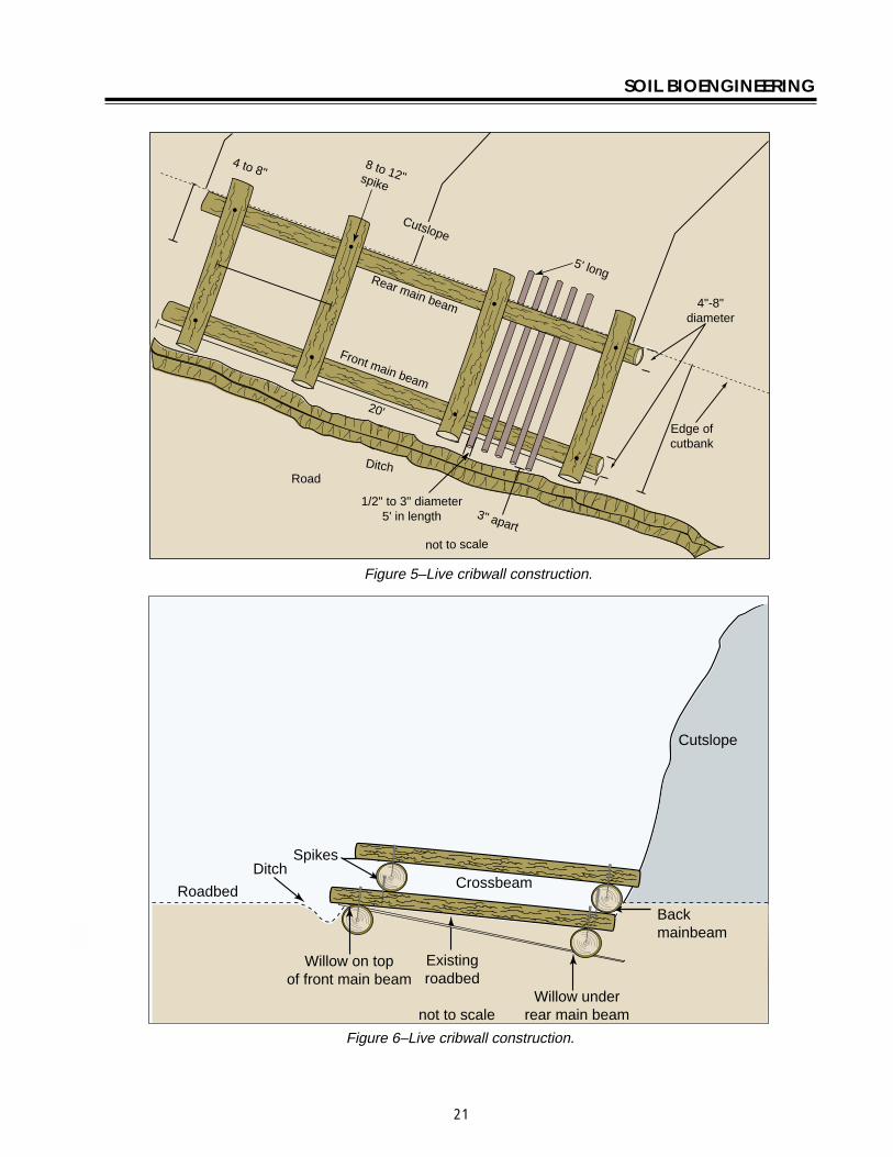
SOIL BIOENGINEERING
Brushlayering Advantages Breaks up slope length into a series of shorter slopes separated by rows of brushlayer Reinforces soil as roots develop adding resistance to sliding or shear displacement Reinforces soil with unrooted branch stems Provides slope stability and allows vegetative cover to become established Traps debris on slope Aids infiltration on dry sites Dries excessively wet sites
Disadvantages Recommended on slopes up to 21 in steepness and not to exceed 15 feet in vertical height Labor intensive
Brushlayering (Sotir and Gray 1982 and 1992) consists of placing live branch cuttings in small terraces excavated into the slopeTerraces can range from 2 to 3 feet wide This technique is similar to live fascine systems because both involve cutting and placement of live branch cuttings on slopes The two techniques differ in the orientation of the branches and depth they are placed in the slope In brushlayering cuttings are oriented perpendicular to slope contour (figure 10) This placement is more effective fromthe pointof view of earth reinforcement and mass shallow stability of the slope
Tools needed Hand pruners and clippers untreated twine (not hemp) pulaski or hazel hoe shovel deadblow or rubber hammer McLeod rake
Digging terraces for brushlayer installation Robbin Sotir amp Associates Brushlayer installation Robbin Sotir amp Associates
Procedure bull Begin project at base of treatment area Excavate
terrace so that approximately 14 of average brush length extends beyond slope face Do not over excavate This technique can trigger soil movements during installation It is important therefore to perform installation in phases and to avoid excavating more area than is necessary to install plant materials (figure 10)
bull Lay an appropriate amount (ie 20 to 25 stems per yard) of single or multiple mix of live brush species along trench sidewall Length of stems can vary from 3 to 4 feet and diameter 12 to 3 inches (figure 10)
bull Stand in completed terrace and begin excavation of second terrace This process allows soil from second terrace above to cover first brushlayer row Compact and slightly mound soil behind brushlayers
bull Move upslope to next trench alignment and repeat process (figure 10)
Brushlayers modified with log terracing installing a short small log (figure 10) can modify brushlayers The log provides additional support to the brushlayer reduces slope angle and serves as a small terrace to ldquocatchrdquo rolling rocks rather than allowing them to roll down the slope and damage vegetation
25
Slope
Installation fall line
direction
SOIL BIOENGINEERING
Brushlayering just after installation Robbin Brushlayering 3 months after installation Sotir amp Associates Robbin Sotir amp Associates
Spacing averages 5-7
Stems 1 14 to 2
diameter
2
3
Spacing 4 to 10
Plant shrubs and trees throughout slope face
To reduce slope angle Live branch cuttings
Log (4 to 6 diameter)
Brushlayer
Length = 2 to 6
Stake
Brushlayer with log terrace
not to scale
Figure 10ndashBrushlayering and brushlayering w log terrace
26
SOIL BIOENGINEERING
Willow fencing with brushlayering USDA Forest Service
Willow Fencing Modified with Brushlayering Advantages These structures reduce slope angle providing a stable platform for vegetation to establish Willow fences trap rolling rocks and sliding debris and protects vegetation growing lower on the slope Willow fences provide support for small shallow translational or rotational failures Sites where fine textured soils can provide ample summer moisture or where seepage of groundwater provides moisture are suitable for willowbrushlayering fence installations These structures can also be constructed on dryer sites however expect high willow mortality In these situations the willow shelf is considered a temporary planting platform It is important therefore to establish deeper rooting shrubs and trees within the shelf When the structure begins to decay root systems of other plants will serve as the permanent feature
Disadvantages Significant quantity of plant material is required Moist site conditions are required for the fence to sprout and grow
Willow fencing with brushlayering is essentially a willow fence supported on a short brushlayer Specifically it is a short retaining wall built of living cuttings with a brushlayer base (figure 11) Willow fencing can also be used without base brushlayering (Polster 1998)
Tools needed Hand pruners and clippers pulaski or hazel hoe McLeod rake deadblow or rubber hammer wood stakes or rebar
Procedure Brushlayering bull Begin project at base of treatment area Excavate
16 to 20 inch deep trenches along slope contour and for full width of treatment area Spacing of trenches averages between 5 to 8 feet full measurement depending on site conditions This technique can cause additional erosion during installation therefore it is important to construct project in phases and to avoid excavating more area than is necessary to install plant materials (figure 11)
12 to 2 diameter
Willow fencing
18 to 36 long stakes 2 to 3 diameter
Brushlayer
18 to 36 long cuttings 1 2 to 2 diameter
Figure 11ndashWillow fencing modified with brushlayering
27
SOIL BIOENGINEERING
bull Lay live brush stems along base of trench Length of stems average 16 inches in length and diameter of 12 to 2 inches Approximately 14 of average brush length should extend beyond slope face (figure 10)
Willow fencing bull Install supporting 18 to 36 inch long wood
stakes cuttings or rebar Average diameter of stakes ranges from 2 to 3 inches
bull Place a few shrub cuttings 18 to 36 inch long and 12 to 2-inch diameter cuttings behind these supports
bull Place enough soil behind these supports to hold the shrub cuttings in place
bull Stand in the trench and begin excavation of second row This process will allow soil from second trench to cover first willow fencing brushlayer row
bull Compact and slightly mound soil on brushlayer and behind willow fence
bull As more soil is added add additional cuttings until the final height of the fence is achieved A goal should be to construct a 21 slope or less between the top of the willow fence and the bottom of the one above
bull Move upslope to next trench alignment and repeat process (figure 11)
Branchpacking just after installation Robbin Sotir amp Associates
Branchpacking Advantages As plant tops grow branchpacking system becomes increasingly effective in retarding runoff and reducing surface erosion Trapped sediment refills localized slumps orholeswhile roots spreadthroughout the backfill and surrounding earth to form a unified mass (figure 12)
Disadvantage Not effective in slump areas greater than 4 feet deep or 5 feet wide
Branchpacking (Sotir and Gray 1992) consists of alternating layers of livebranch cuttings and compacted backfill to repair small localized slumps and holes (figure 12)
Tools needed Hand pruners and clippers deadblow or rubber hammer untreated twine McLeod rake shovel wood stakes
Branchpacking just after installation Robbin Sotir amp Associates
28
SOIL BIOENGINEERING
Branchpacking post installation Robbin Sotir amp Associates
Procedure bull Starting at lowest point drive wooden stakes
vertically 3 to 4 feet into the ground Set them 1- to 1 12 -feet apart Wooden stakes should be 5 to 8 feet long and made from 3-to-4 inch diameter poles or 2 by 4 lumber depending upon depth of particular slump or hole
bull Place a layer of live cut branches 4 to 6 inches thick in bottom of hole between vertical stakes and perpendicular to the slope face (figure 12) Crisscross branches with growing tips generally oriented toward slope face Some basal ends of branches should touch the back of the slope
bull Install subsequent layers with basal ends lower than the growing tips of the branches This is to insure developing root systems will be located at water collection points on the slope
bull Each layer of branches must be followed by a layer of compacted soil to ensure soil contact with branch cuttings
bull Final installation should match existing slope Branches should protrude only slightly from the filled face
bull The soil should be moist or moistened to insure live branches do not dry out
1 to 1-12
Live branch cuttings 14 to 2 diameter
Compact fill material
Wooden stakes 5 to 8 long 2 x 4 lumber driven 3 to 4 into undisturbed soil
4 to 6 inch layer of live branch cuttings laid criss cross and
touching back of hole
Live branch cuttings should protrude slightly from
backfill area
Several weeks or months later
spacing not to scale
Figure 12ndashBranchpacking
29
SOIL BIOENGINEERING
3 to 4 inch layer of live branch cuttings laid in crisscross and touching undisturbed soil on gully bed
Several weeks later
Live branch cuttings 1 to 2 in diameter
Compacted fill material 6 to 8 layer
Gully bed
Figure 13ndashLive gully repair
Live Gully Repair Advantages Offers immediate reinforcement to compacted soil reduces velocity of concentrated flow of water and provides a filter barrier to reduce rill and gully erosion
Disadvantages Limited to rills and gullies which are a maximum of 2-feet wide 1-foot deep and 15- feet long
Live gully repair (Sotir and Gray 1992) utilizes alternating layers of live branch cuttings and compacted soil to repair small rills and gullies Similar to branchpacking this method is more appropriate for repair of rills and gullies
Tools needed Hand pruners and clippers shovel McLeod rake untreated twine
Procedure bull Starting at lowest point of the slope place a 3shy
to 4-inch thick layer of live cut branches at lowest end of the rill or gully and perpendicular to the slope (figure 13)
bull Cover with 6-to 8-inch layer of soil
bull Install live cut branches in a crisscross fashion Orient growing tips toward slope face with basal ends lower than growing tips
bull Follow each layer of branches with a layer of compacted soil to ensure soil contact with live branch cuttings
30
SOIL BIOENGINEERING
Figure 14ndashVegetated geotextile
Vegetated Geotextile Advantages Retards rill and gully erosion stabilizes fill banks Is less expensive than other retaining walls such as gabion or Hilfiker baskets
Disadvantage Can be expensive if heavy equipment required
Synthetic or organic geotextile wrapped around lifts of soil with a mix of live branches placed between layers There are numerous opportunites of blending geotechnical-engineered systems with soil bioengineering The following is one example
Tools needed Backhoe geotextile hand pruners and clippers McLeod rake shovel untreated twine
Procedure bull Excavate lower edge of slope break and bench
backcut Compact the soil layer Note Structural integrity is dependent on compacted soil layers Even with mechanized firming soils support live cuttings
bull Lay first layer of geotextile down into the bench
bull Fill lowest lift with gravel fold back and stake securely
bull Fill subsequent layers with soil and layers of live cut branches (figure 10) and alternate with lifts (figure 14) Each layer must be compacted
bull The structure can be built with a vertical face or stair-stepped and sloped back into the hillside
31
SOIL BIOENGINEERING
Installation - cutslope stabilzation with log terracing USDA Forest Service
Log Terracing Advantages Logs create terraces reducing length and steepness of slope provides stable areas for establishment of other vegetation such as trees and shrubs
Disadvantages Labor intensive and with potential safety hazards
Tools needed Chainsaw PV pole blocks and cable power winch shackles and chokers pulaski Mcleod and shovel wood stakes hand pruner and clippers traffic control signs
Procedure bull The technique utilizes alternating terraced logs
to stop surface erosion on eroding slopes Stopping the erosion is critical for successful revegetation efforts Specifically log terracing shortens slope length and gradient between each structure providing stable planting areas throughout most of the slope face (figure 15)
bull Prior to beginning a log terracing project place traffic control signs several hundred feet on both sides of your project area Then climb slope to locate and remove potential safety hazards These hazards include loose tree root wads unstable rocks and boulders This inspection will also provide a different visual
perspective of the site This ldquotop-downrdquo viewpoint is usually the best place to formulate your project design
bull Begin log terracing at the base of the slope and work your way uphill This should prevent undercutting of any terrace or log you place above It also provides a stable and secure footing area for project work
bull Log terracing consists primarily of 3 main steps These steps include moving installing and anchoring logs to specified points on an eroding hillside
Moving bull Try not to cause any additional erosion or
damage log terraces you have already excavated This can be accomplished by setting up a skyline or carefully using a straight dragline with block and cable
Installation bull Use a minimum of 12-inch diameter logs
Sixteen or 20-inch diameter logs work best The most common error in log terracing is using logs that are too small in diameter
bull Use existing slope features such as tree stumps rock outcroppings or natural slope benches to secure one or both ends of the logs These natural features make project work easier safer and work better than stakes or rebar for keeping the log in place on the slope
bull Excavate terraces 13 the width of the log diameter deep and for full length of the log With rope (or cable) blocks and winch place the logs into position (figure 16)
Anchoring bull Depending on site conditions attempt to space
log terraces 10 to 20 feet apart
32
SOIL BIOENGINEERING
bull Anchor logs into the slope using 3-to 5-inch should be inserted into the ground Bend over diameter wood stakes or 34 inch rebar any excess rebar
bull Stake length should be 4 times the diameter of the log A 12-inch diameter log for example would require 48-inch long stakes and a 16shyinch diameter log 64-inch long stakes
bull Once in place drive stakes vertically into slope just below the log Two thirds of the stake should be driven into the ground These stakes should be spaced every 4 feet across the length of the log (figure 17) Another recommended technique is to drill holes through the log and anchor with rebar Two thirds of total length
bull When utilizing tree stumps and rock outcroppings for anchor points gaps may occur between log and soil surface This gap must be filled To do so excavate a trench uphill from the log and place a smaller log flush with the log structure (figure 17)
bull There are many possible patterns for log terracing The following 3 have proved useful for stabilization efforts (figure 15) Whatever pattern utilized it is absolutely critical no gaps exist between the log and soil surface
Erosion site Erosion site Erosion site
Retaining structure Retaining structure Retaining structure
15-20
15-20
Shortened slope distance 50 failure
width
Rock
20
Treestump
Staggered Pattern Ladder Pattern Building Block Pattern
not to scale
Figure 15ndashLog terrace installation
33
SOIL BIOENGINEERING
Staggered Using logs with lengths greater than 50 percent of the width of the erosion site These logs should overlap each other and be anchored into stable soils on either side of the failure site
Ladder Logs extend across full width of erosion site and should be anchored into stable soils on either side of failure site
Building block This method best mimics what happens naturally on an eroding slope Begin the project at the slope base This area is stable and will provide a secure base to build off of as you work your way up slope There is no set pattern Design and log placement pattern will evolve as the project progresses Be creative
bull Once the slope has been stabilized with log terracing it is critical to address the upper portion of the slope failure This area is often referred to as the slope overhang Addressing this area is critical since it is the source of the surface erosion Without removing this erosion source project success is unlikely Cut away the overhang so slope angle will allow seed to germinate and plants to establish Try to angle the slope to blend with the new slope gradient created with log terracing Often this will require a cut 5 to 6 feet upslope This is the most difficult portion of a log terracing project and will often result in removing vegetation This vegetation however can be transplanted to other areas on the slope
34
SOIL BIOENGINEERING
Use of existing slope features
Stump
Rock
Front view trench construction
Trench
Place log 13 of diameter deep
Slope
Place log 13 of diameter deep
Trench construction side view
Stakes
not to scale
Figure 16ndashLog terrace construction
Formula A 12 diameter log needs 48 long stakes
Trench
Stake 13 above
Stake 23 below
Stakes
Front view
Erosion site
Log
Cutslope
Roadbed
Vertical placement
Side view
Erosion site
Stake 13 above ground
Stake 23 below ground
Ground level
Gap
Ground level
Filler log
not to scale
Figure 17ndashAnchoring and filling gaps
35
SOIL BIOENGINEERING
Roadbed Ditch
Cutslope
Fill slope
Slope overhang
Slope overhang
Area to remove
Area to remove
not to scale
Figure 18ndashRemoval of slope overhang
36
SOIL BIOENGINEERING
Bender Board Fencing Advantages These structures reduce slope angle providing a stable platform for vegetation to establish Like willow fencing bender board structures trap rolling rocks and sliding debris and protects vegetation growing lower on the slope Bender board fences provide support for small translational or rotational failures
Dry sites where soils receive very little precipitation this type of structure The bender board shelf is considered a temporary planting platform It is important therefore to establish deeper rooting shrubs and trees within the shelves When the structures begins to decay root systems of other plants will serve as the permanent feature
Disadvantage Significant quantity of plant material is required
Redwood or cedar bender board fencing is essentially a fence supported on a short layer of shrub or tree stems Specifically it is a short retaining wall built of redwood or cedar bender fencing with a stem layered base
Tools needed Hand pruners and clippers pulaski or hazel hoe McLeod rake deadblow or rubber hammer wood stakes
Procedure Stem Layered Base bull Begin project at base of treatment area Excavate a
24-inch deep terrace along slope contour and for full width of treatment area The back of the terrace should be dug with an approximate 70 degree angle To allow ample planting platforms space terraces about 5 feet apart
bull Lay 2 feet 6-inch long stems and 2 feet 6-inch long wood stakes (5050 mix) 2-inches apart and for full length of terrace Diameter can range from 12 to 2-inches Approximatly 6-inches will extend beyond slope face
Bender board Fencing bull Drive supporting 4 foot 6-inch (2 by 2) long stakes
2 to 3 feet into ground spaced 1 foot apart and perpendicular to the slope Rebar may be used instead of wooden stakes
bull Weave 10 foot long bender boards through these stakes until the wall reaches a height of 2 feet Once complete the bender board fence wall should be at a 15 degree angle to the slope Note As shown in photo some bender board are too brittle to weave
bull Once the wall frame is constructed carefully rake enough soil into the terrace to cover the stem layered base
37
SOIL BIOENGINEERING
bull Stand in terrace and begin excavation of second bull Move upslope to next terrace alignment and row This process will allow soil into the terrace repeat process to cover the stem layered base
bull A goal should be to construct a 21 slope or less between the top of the bender board fence wall and the bottom of the one above
10 foot long bender boards 14 thick 3-12 wide
2-6 long stakes spaced 3 apart
2 high seven bender boards
2 wide terraces spaced 5 apart
not to scale
4-6 post buried 2-3
Figure 19ndashBender board fencing
38
SOIL BIOENGINEERING
REFERENCES CITED
Bach David H and MacAskill IA 1984 Vegetation and Landscape Engineering Granada London
Bennett Francis W 1975 Methods of Quickly Vegetating Soils of Low Productivity Construction Activities US Environmental Protection Agency Washington DC
Brosius Myra 1985 ldquoThe Restoration of an Urban Stream Using Geomorphic Relationships and Biotechnical Streambank Stabilizationrdquo Athens GA University of Georgia Thesis
Chandler RJ 1991 Slope Stability Engineering Institution of Civil Engineers Thomas Telford Publishing Company
Chatwin S D Howes and D Swantson 1994 A Guide for Management of Landslide Prone Terrain in the Pacific Northwest Second edition Ministry of Forests Crown Publications Victoria BC
Christensen M and J Jacobovitch 1992 Revegetation Projects Everything You Wanted to Know About Live Staking Unpublished report for King County Dept of Public Works Surface Water Management Div Seattle WA
Coppin NJ and IG Richards 1990 Use of Vegetation in Civil Engineering Butterworths London England
Coppin Nick J and R Stiles 1989 The Use of Vegetation in Slope Stabilization Landscape Design with Plants Second Edition ed by Brian Clouston Boca Raton Florida CRC Press 212-234
Edlin HL 1949 Woodland Crafts in Britain BT London Batsford Ltd London
Finney Kevin P 1993 BioEngineering Solutions A Tool for Education Eugene OR University of Oregon Thesis
Finney K 1993 History of Soil Bioengineering Eugene OR Masters Thesis University of Oregon Thesis
Gray DR and AT Leiser 1982 Biotechnical Slope Protection and Erosion Control New YorkVan Nostrand Reinhold Company New York
Gray DH Leiser T Andrew and C A White 1980 Combined Vegetative Structural Slope Stabilization Civil Engineering 50(1)82-85
Gray D R and Sotir RB 1996 Biotechnical and Soil Bioengineering Slope Stabilization John Wiley and Sons Inc
Greenway DR 1987 Vegetation and Slope Stability In Slope Stability John Wiley and Sons Ltd Chapter 6
41
SOIL BIOENGINEERING
Johnson AW and JM Stypula eds 1993 Guidelines for Bank Stabilization Projects In the Rivetine Environments of King County County Department of Public Works Surface Water Management Division Seattle WA
Kraebel CJ 1936 Erosion Control on Mountain Roads USDA Circular No 380 Washington DC USDA
Kraebel CJ 1933 Willow Cuttings for Erosion Control Technical Note No 1 Berkely California USDA California Forest Experiment Station
Larson FE and WE Guse 1981 Propagating Deciduous and Evergreen Shrubs Trees and Vines with Stem Cuttings Pacific Northwest Coop Ext Pub PNW152
Leiser Andrew T J J Nussbaum Kay Burgess Paul Jack and W Thornhill 1974 Revegetation of Disturbed Soils in the Tahoe Basin California Department of Transportation Sacramento California
Lewis EA and LW Ogg 1993 Soil Bioengineering Project Descriptions Unpublished report for Olympic National Forest Hood Canal Hanger District
Leys Emil 1978 Wilhelm Hassenteufel 80 Years Old Garten und Landschaft in China Vol 4 Part 3 Cambridge The University Press
Maleike R and RL Hummel 1988 Planting Landscape Plants Wash State Univ Coop Ext Pub EB1505
Polster Environmental Services 1998 Soil Bioengineering for Forest Land Reclamation and Stabilization British Columbia Ministry of Forests
Robbin B Sotir amp Associates A Brief History of Soil Bioengineering Unpublished and undated manuscript
Schiechtl Hugo 1980 Bioengineering For Land Reclamation and Conservation Edmonton Canada The University of Alberta Press
Schiechtl H M and R Stern 1997 Ground Bioengineering Techniques for Slope Protection and Erosion Control Blackwell Science Publications ISBN 0-632-04061-0
Sotir RB and DH Gray 1992 Soil Bioengineering for Upland Slope Protection and Erosion Reduction Engineering Field Handbook Soil Conservation Service Chapter 18
Stiles Richard (172) 57-61 1988 Engineering with Vegetation Landscape Design (172) 57-61
Stiles Richard1991 Re-inventing the Wheel Landscape Design (203)
42
SOIL BIOENGINEERING
Weaver WE and MA Madej 1981 Erosion Control Techniques Used in Redwood National Park In Davies TRH and AJ Pearce eds Erosion and Sediment Transport in Pacific Rim Steeplands Washington DC Intrsquol Assoc Hydrological Sciences 640-654 IAHS-AISH Pub 132
Westmacott Richard 1985 The Rediscovered Arts of Twilling and Wattling Landscape Architecture 75(4)95-98
White Charles A and AL Frank S 1978 Demonstration of Erosion and Sediment Control Technology Lake Tahoe Region of California EPA-6002-78-208 Municipal Environmental Research Laboratory Office of Research and Development US Environmental Protection Agency Cincinnati Ohio
Ziemer RR 1981 Roots and the Stability of Forested Slopes In Davies TRH and AJ Pearce eds Erosion and Sediment Transport in Pacific Rim Steeplands
43
SOIL BIOENGINEERING
About the Authorhellip
Lisa Lewis graduated in 1987 from Fort Valley State University Fort Valley Georgia with a Bachelor of Science degree in Soil and Plant Sciences Lisa began her career with the Forest Service in August 1987 on the Hood Canal Ranger District She continued her career in the Pacific Northwest and since 1998 she has been a soil scientist with the National Riparian Service Team (NRST) As a member of the NRST Lisa provides training and technology transfer consulting and advisory services and program review for riparian restoration nationwide She specializes in road management issues and soil bioengineering techniques
Library Card
Lewis Lisa 2000 Soil bioengineeringmdashan alternative to roadside managementmdasha practical guide Technical Report 0077-1801-SDTDC San Dimas CA US Department of Agriculture Forest Service San Dimas Technology and Development Center 44 p
This publication provides field personnel with the basic merits of soil bioengineering concepts and gives examples of several techniques especially effective in stabilizing and revegetating upland roadside environments The information provided in this document is intended to stimulate additional interest for the reader to seek out and use these and other soil bioengineering applications
Soil bioengineering is the use of live plant materials and flexible engineering techniques to alleviate environmental problems such as destabilized and eroding slopes Unlike other technologies in which plants are chiefly an aesthetic component of the project in soil bioengineering systems plants are an important structural component
Keywords Soil bioengineering road management road maintenance restoration erosion native plant materials revegetation
Additional single copies of this document may be ordered from
USDA Forest Service San Dimas Technology and Development Center
ATTN Richard Martinez 444 E Bonita Avenue San Dimas CA 91773
Phone (909) 599-1267 x201 Fax (909) 592-2309
E-Mail rmartinezwo_sdtdcfsfedus FSNotes Richard MartinezWOUSDAFS
For additional technical information contact Lisa Lewis at the following address
USDA Forest Service National Riparian Service Team
3050 NE 3rd Street PO Box 550
Prineville OR 98854 Phone (541) 416-6788
E-Mail l3Lewisorblmgov
An electronic copy of this document is available on the Forest Servicersquos FSWeb
Intranet at httpfswebsdtdcwofsfedus

Slope
Installation fall line
direction
SOIL BIOENGINEERING
Brushlayering just after installation Robbin Brushlayering 3 months after installation Sotir amp Associates Robbin Sotir amp Associates
Spacing averages 5-7
Stems 1 14 to 2
diameter
2
3
Spacing 4 to 10
Plant shrubs and trees throughout slope face
To reduce slope angle Live branch cuttings
Log (4 to 6 diameter)
Brushlayer
Length = 2 to 6
Stake
Brushlayer with log terrace
not to scale
Figure 10ndashBrushlayering and brushlayering w log terrace
26
SOIL BIOENGINEERING
Willow fencing with brushlayering USDA Forest Service
Willow Fencing Modified with Brushlayering Advantages These structures reduce slope angle providing a stable platform for vegetation to establish Willow fences trap rolling rocks and sliding debris and protects vegetation growing lower on the slope Willow fences provide support for small shallow translational or rotational failures Sites where fine textured soils can provide ample summer moisture or where seepage of groundwater provides moisture are suitable for willowbrushlayering fence installations These structures can also be constructed on dryer sites however expect high willow mortality In these situations the willow shelf is considered a temporary planting platform It is important therefore to establish deeper rooting shrubs and trees within the shelf When the structure begins to decay root systems of other plants will serve as the permanent feature
Disadvantages Significant quantity of plant material is required Moist site conditions are required for the fence to sprout and grow
Willow fencing with brushlayering is essentially a willow fence supported on a short brushlayer Specifically it is a short retaining wall built of living cuttings with a brushlayer base (figure 11) Willow fencing can also be used without base brushlayering (Polster 1998)
Tools needed Hand pruners and clippers pulaski or hazel hoe McLeod rake deadblow or rubber hammer wood stakes or rebar
Procedure Brushlayering bull Begin project at base of treatment area Excavate
16 to 20 inch deep trenches along slope contour and for full width of treatment area Spacing of trenches averages between 5 to 8 feet full measurement depending on site conditions This technique can cause additional erosion during installation therefore it is important to construct project in phases and to avoid excavating more area than is necessary to install plant materials (figure 11)
12 to 2 diameter
Willow fencing
18 to 36 long stakes 2 to 3 diameter
Brushlayer
18 to 36 long cuttings 1 2 to 2 diameter
Figure 11ndashWillow fencing modified with brushlayering
27
SOIL BIOENGINEERING
bull Lay live brush stems along base of trench Length of stems average 16 inches in length and diameter of 12 to 2 inches Approximately 14 of average brush length should extend beyond slope face (figure 10)
Willow fencing bull Install supporting 18 to 36 inch long wood
stakes cuttings or rebar Average diameter of stakes ranges from 2 to 3 inches
bull Place a few shrub cuttings 18 to 36 inch long and 12 to 2-inch diameter cuttings behind these supports
bull Place enough soil behind these supports to hold the shrub cuttings in place
bull Stand in the trench and begin excavation of second row This process will allow soil from second trench to cover first willow fencing brushlayer row
bull Compact and slightly mound soil on brushlayer and behind willow fence
bull As more soil is added add additional cuttings until the final height of the fence is achieved A goal should be to construct a 21 slope or less between the top of the willow fence and the bottom of the one above
bull Move upslope to next trench alignment and repeat process (figure 11)
Branchpacking just after installation Robbin Sotir amp Associates
Branchpacking Advantages As plant tops grow branchpacking system becomes increasingly effective in retarding runoff and reducing surface erosion Trapped sediment refills localized slumps orholeswhile roots spreadthroughout the backfill and surrounding earth to form a unified mass (figure 12)
Disadvantage Not effective in slump areas greater than 4 feet deep or 5 feet wide
Branchpacking (Sotir and Gray 1992) consists of alternating layers of livebranch cuttings and compacted backfill to repair small localized slumps and holes (figure 12)
Tools needed Hand pruners and clippers deadblow or rubber hammer untreated twine McLeod rake shovel wood stakes
Branchpacking just after installation Robbin Sotir amp Associates
28
SOIL BIOENGINEERING
Branchpacking post installation Robbin Sotir amp Associates
Procedure bull Starting at lowest point drive wooden stakes
vertically 3 to 4 feet into the ground Set them 1- to 1 12 -feet apart Wooden stakes should be 5 to 8 feet long and made from 3-to-4 inch diameter poles or 2 by 4 lumber depending upon depth of particular slump or hole
bull Place a layer of live cut branches 4 to 6 inches thick in bottom of hole between vertical stakes and perpendicular to the slope face (figure 12) Crisscross branches with growing tips generally oriented toward slope face Some basal ends of branches should touch the back of the slope
bull Install subsequent layers with basal ends lower than the growing tips of the branches This is to insure developing root systems will be located at water collection points on the slope
bull Each layer of branches must be followed by a layer of compacted soil to ensure soil contact with branch cuttings
bull Final installation should match existing slope Branches should protrude only slightly from the filled face
bull The soil should be moist or moistened to insure live branches do not dry out
1 to 1-12
Live branch cuttings 14 to 2 diameter
Compact fill material
Wooden stakes 5 to 8 long 2 x 4 lumber driven 3 to 4 into undisturbed soil
4 to 6 inch layer of live branch cuttings laid criss cross and
touching back of hole
Live branch cuttings should protrude slightly from
backfill area
Several weeks or months later
spacing not to scale
Figure 12ndashBranchpacking
29
SOIL BIOENGINEERING
3 to 4 inch layer of live branch cuttings laid in crisscross and touching undisturbed soil on gully bed
Several weeks later
Live branch cuttings 1 to 2 in diameter
Compacted fill material 6 to 8 layer
Gully bed
Figure 13ndashLive gully repair
Live Gully Repair Advantages Offers immediate reinforcement to compacted soil reduces velocity of concentrated flow of water and provides a filter barrier to reduce rill and gully erosion
Disadvantages Limited to rills and gullies which are a maximum of 2-feet wide 1-foot deep and 15- feet long
Live gully repair (Sotir and Gray 1992) utilizes alternating layers of live branch cuttings and compacted soil to repair small rills and gullies Similar to branchpacking this method is more appropriate for repair of rills and gullies
Tools needed Hand pruners and clippers shovel McLeod rake untreated twine
Procedure bull Starting at lowest point of the slope place a 3shy
to 4-inch thick layer of live cut branches at lowest end of the rill or gully and perpendicular to the slope (figure 13)
bull Cover with 6-to 8-inch layer of soil
bull Install live cut branches in a crisscross fashion Orient growing tips toward slope face with basal ends lower than growing tips
bull Follow each layer of branches with a layer of compacted soil to ensure soil contact with live branch cuttings
30
SOIL BIOENGINEERING
Figure 14ndashVegetated geotextile
Vegetated Geotextile Advantages Retards rill and gully erosion stabilizes fill banks Is less expensive than other retaining walls such as gabion or Hilfiker baskets
Disadvantage Can be expensive if heavy equipment required
Synthetic or organic geotextile wrapped around lifts of soil with a mix of live branches placed between layers There are numerous opportunites of blending geotechnical-engineered systems with soil bioengineering The following is one example
Tools needed Backhoe geotextile hand pruners and clippers McLeod rake shovel untreated twine
Procedure bull Excavate lower edge of slope break and bench
backcut Compact the soil layer Note Structural integrity is dependent on compacted soil layers Even with mechanized firming soils support live cuttings
bull Lay first layer of geotextile down into the bench
bull Fill lowest lift with gravel fold back and stake securely
bull Fill subsequent layers with soil and layers of live cut branches (figure 10) and alternate with lifts (figure 14) Each layer must be compacted
bull The structure can be built with a vertical face or stair-stepped and sloped back into the hillside
31
SOIL BIOENGINEERING
Installation - cutslope stabilzation with log terracing USDA Forest Service
Log Terracing Advantages Logs create terraces reducing length and steepness of slope provides stable areas for establishment of other vegetation such as trees and shrubs
Disadvantages Labor intensive and with potential safety hazards
Tools needed Chainsaw PV pole blocks and cable power winch shackles and chokers pulaski Mcleod and shovel wood stakes hand pruner and clippers traffic control signs
Procedure bull The technique utilizes alternating terraced logs
to stop surface erosion on eroding slopes Stopping the erosion is critical for successful revegetation efforts Specifically log terracing shortens slope length and gradient between each structure providing stable planting areas throughout most of the slope face (figure 15)
bull Prior to beginning a log terracing project place traffic control signs several hundred feet on both sides of your project area Then climb slope to locate and remove potential safety hazards These hazards include loose tree root wads unstable rocks and boulders This inspection will also provide a different visual
perspective of the site This ldquotop-downrdquo viewpoint is usually the best place to formulate your project design
bull Begin log terracing at the base of the slope and work your way uphill This should prevent undercutting of any terrace or log you place above It also provides a stable and secure footing area for project work
bull Log terracing consists primarily of 3 main steps These steps include moving installing and anchoring logs to specified points on an eroding hillside
Moving bull Try not to cause any additional erosion or
damage log terraces you have already excavated This can be accomplished by setting up a skyline or carefully using a straight dragline with block and cable
Installation bull Use a minimum of 12-inch diameter logs
Sixteen or 20-inch diameter logs work best The most common error in log terracing is using logs that are too small in diameter
bull Use existing slope features such as tree stumps rock outcroppings or natural slope benches to secure one or both ends of the logs These natural features make project work easier safer and work better than stakes or rebar for keeping the log in place on the slope
bull Excavate terraces 13 the width of the log diameter deep and for full length of the log With rope (or cable) blocks and winch place the logs into position (figure 16)
Anchoring bull Depending on site conditions attempt to space
log terraces 10 to 20 feet apart
32
SOIL BIOENGINEERING
bull Anchor logs into the slope using 3-to 5-inch should be inserted into the ground Bend over diameter wood stakes or 34 inch rebar any excess rebar
bull Stake length should be 4 times the diameter of the log A 12-inch diameter log for example would require 48-inch long stakes and a 16shyinch diameter log 64-inch long stakes
bull Once in place drive stakes vertically into slope just below the log Two thirds of the stake should be driven into the ground These stakes should be spaced every 4 feet across the length of the log (figure 17) Another recommended technique is to drill holes through the log and anchor with rebar Two thirds of total length
bull When utilizing tree stumps and rock outcroppings for anchor points gaps may occur between log and soil surface This gap must be filled To do so excavate a trench uphill from the log and place a smaller log flush with the log structure (figure 17)
bull There are many possible patterns for log terracing The following 3 have proved useful for stabilization efforts (figure 15) Whatever pattern utilized it is absolutely critical no gaps exist between the log and soil surface
Erosion site Erosion site Erosion site
Retaining structure Retaining structure Retaining structure
15-20
15-20
Shortened slope distance 50 failure
width
Rock
20
Treestump
Staggered Pattern Ladder Pattern Building Block Pattern
not to scale
Figure 15ndashLog terrace installation
33
SOIL BIOENGINEERING
Staggered Using logs with lengths greater than 50 percent of the width of the erosion site These logs should overlap each other and be anchored into stable soils on either side of the failure site
Ladder Logs extend across full width of erosion site and should be anchored into stable soils on either side of failure site
Building block This method best mimics what happens naturally on an eroding slope Begin the project at the slope base This area is stable and will provide a secure base to build off of as you work your way up slope There is no set pattern Design and log placement pattern will evolve as the project progresses Be creative
bull Once the slope has been stabilized with log terracing it is critical to address the upper portion of the slope failure This area is often referred to as the slope overhang Addressing this area is critical since it is the source of the surface erosion Without removing this erosion source project success is unlikely Cut away the overhang so slope angle will allow seed to germinate and plants to establish Try to angle the slope to blend with the new slope gradient created with log terracing Often this will require a cut 5 to 6 feet upslope This is the most difficult portion of a log terracing project and will often result in removing vegetation This vegetation however can be transplanted to other areas on the slope
34
SOIL BIOENGINEERING
Use of existing slope features
Stump
Rock
Front view trench construction
Trench
Place log 13 of diameter deep
Slope
Place log 13 of diameter deep
Trench construction side view
Stakes
not to scale
Figure 16ndashLog terrace construction
Formula A 12 diameter log needs 48 long stakes
Trench
Stake 13 above
Stake 23 below
Stakes
Front view
Erosion site
Log
Cutslope
Roadbed
Vertical placement
Side view
Erosion site
Stake 13 above ground
Stake 23 below ground
Ground level
Gap
Ground level
Filler log
not to scale
Figure 17ndashAnchoring and filling gaps
35
SOIL BIOENGINEERING
Roadbed Ditch
Cutslope
Fill slope
Slope overhang
Slope overhang
Area to remove
Area to remove
not to scale
Figure 18ndashRemoval of slope overhang
36
SOIL BIOENGINEERING
Bender Board Fencing Advantages These structures reduce slope angle providing a stable platform for vegetation to establish Like willow fencing bender board structures trap rolling rocks and sliding debris and protects vegetation growing lower on the slope Bender board fences provide support for small translational or rotational failures
Dry sites where soils receive very little precipitation this type of structure The bender board shelf is considered a temporary planting platform It is important therefore to establish deeper rooting shrubs and trees within the shelves When the structures begins to decay root systems of other plants will serve as the permanent feature
Disadvantage Significant quantity of plant material is required
Redwood or cedar bender board fencing is essentially a fence supported on a short layer of shrub or tree stems Specifically it is a short retaining wall built of redwood or cedar bender fencing with a stem layered base
Tools needed Hand pruners and clippers pulaski or hazel hoe McLeod rake deadblow or rubber hammer wood stakes
Procedure Stem Layered Base bull Begin project at base of treatment area Excavate a
24-inch deep terrace along slope contour and for full width of treatment area The back of the terrace should be dug with an approximate 70 degree angle To allow ample planting platforms space terraces about 5 feet apart
bull Lay 2 feet 6-inch long stems and 2 feet 6-inch long wood stakes (5050 mix) 2-inches apart and for full length of terrace Diameter can range from 12 to 2-inches Approximatly 6-inches will extend beyond slope face
Bender board Fencing bull Drive supporting 4 foot 6-inch (2 by 2) long stakes
2 to 3 feet into ground spaced 1 foot apart and perpendicular to the slope Rebar may be used instead of wooden stakes
bull Weave 10 foot long bender boards through these stakes until the wall reaches a height of 2 feet Once complete the bender board fence wall should be at a 15 degree angle to the slope Note As shown in photo some bender board are too brittle to weave
bull Once the wall frame is constructed carefully rake enough soil into the terrace to cover the stem layered base
37
SOIL BIOENGINEERING
bull Stand in terrace and begin excavation of second bull Move upslope to next terrace alignment and row This process will allow soil into the terrace repeat process to cover the stem layered base
bull A goal should be to construct a 21 slope or less between the top of the bender board fence wall and the bottom of the one above
10 foot long bender boards 14 thick 3-12 wide
2-6 long stakes spaced 3 apart
2 high seven bender boards
2 wide terraces spaced 5 apart
not to scale
4-6 post buried 2-3
Figure 19ndashBender board fencing
38
SOIL BIOENGINEERING
REFERENCES CITED
Bach David H and MacAskill IA 1984 Vegetation and Landscape Engineering Granada London
Bennett Francis W 1975 Methods of Quickly Vegetating Soils of Low Productivity Construction Activities US Environmental Protection Agency Washington DC
Brosius Myra 1985 ldquoThe Restoration of an Urban Stream Using Geomorphic Relationships and Biotechnical Streambank Stabilizationrdquo Athens GA University of Georgia Thesis
Chandler RJ 1991 Slope Stability Engineering Institution of Civil Engineers Thomas Telford Publishing Company
Chatwin S D Howes and D Swantson 1994 A Guide for Management of Landslide Prone Terrain in the Pacific Northwest Second edition Ministry of Forests Crown Publications Victoria BC
Christensen M and J Jacobovitch 1992 Revegetation Projects Everything You Wanted to Know About Live Staking Unpublished report for King County Dept of Public Works Surface Water Management Div Seattle WA
Coppin NJ and IG Richards 1990 Use of Vegetation in Civil Engineering Butterworths London England
Coppin Nick J and R Stiles 1989 The Use of Vegetation in Slope Stabilization Landscape Design with Plants Second Edition ed by Brian Clouston Boca Raton Florida CRC Press 212-234
Edlin HL 1949 Woodland Crafts in Britain BT London Batsford Ltd London
Finney Kevin P 1993 BioEngineering Solutions A Tool for Education Eugene OR University of Oregon Thesis
Finney K 1993 History of Soil Bioengineering Eugene OR Masters Thesis University of Oregon Thesis
Gray DR and AT Leiser 1982 Biotechnical Slope Protection and Erosion Control New YorkVan Nostrand Reinhold Company New York
Gray DH Leiser T Andrew and C A White 1980 Combined Vegetative Structural Slope Stabilization Civil Engineering 50(1)82-85
Gray D R and Sotir RB 1996 Biotechnical and Soil Bioengineering Slope Stabilization John Wiley and Sons Inc
Greenway DR 1987 Vegetation and Slope Stability In Slope Stability John Wiley and Sons Ltd Chapter 6
41
SOIL BIOENGINEERING
Johnson AW and JM Stypula eds 1993 Guidelines for Bank Stabilization Projects In the Rivetine Environments of King County County Department of Public Works Surface Water Management Division Seattle WA
Kraebel CJ 1936 Erosion Control on Mountain Roads USDA Circular No 380 Washington DC USDA
Kraebel CJ 1933 Willow Cuttings for Erosion Control Technical Note No 1 Berkely California USDA California Forest Experiment Station
Larson FE and WE Guse 1981 Propagating Deciduous and Evergreen Shrubs Trees and Vines with Stem Cuttings Pacific Northwest Coop Ext Pub PNW152
Leiser Andrew T J J Nussbaum Kay Burgess Paul Jack and W Thornhill 1974 Revegetation of Disturbed Soils in the Tahoe Basin California Department of Transportation Sacramento California
Lewis EA and LW Ogg 1993 Soil Bioengineering Project Descriptions Unpublished report for Olympic National Forest Hood Canal Hanger District
Leys Emil 1978 Wilhelm Hassenteufel 80 Years Old Garten und Landschaft in China Vol 4 Part 3 Cambridge The University Press
Maleike R and RL Hummel 1988 Planting Landscape Plants Wash State Univ Coop Ext Pub EB1505
Polster Environmental Services 1998 Soil Bioengineering for Forest Land Reclamation and Stabilization British Columbia Ministry of Forests
Robbin B Sotir amp Associates A Brief History of Soil Bioengineering Unpublished and undated manuscript
Schiechtl Hugo 1980 Bioengineering For Land Reclamation and Conservation Edmonton Canada The University of Alberta Press
Schiechtl H M and R Stern 1997 Ground Bioengineering Techniques for Slope Protection and Erosion Control Blackwell Science Publications ISBN 0-632-04061-0
Sotir RB and DH Gray 1992 Soil Bioengineering for Upland Slope Protection and Erosion Reduction Engineering Field Handbook Soil Conservation Service Chapter 18
Stiles Richard (172) 57-61 1988 Engineering with Vegetation Landscape Design (172) 57-61
Stiles Richard1991 Re-inventing the Wheel Landscape Design (203)
42
SOIL BIOENGINEERING
Weaver WE and MA Madej 1981 Erosion Control Techniques Used in Redwood National Park In Davies TRH and AJ Pearce eds Erosion and Sediment Transport in Pacific Rim Steeplands Washington DC Intrsquol Assoc Hydrological Sciences 640-654 IAHS-AISH Pub 132
Westmacott Richard 1985 The Rediscovered Arts of Twilling and Wattling Landscape Architecture 75(4)95-98
White Charles A and AL Frank S 1978 Demonstration of Erosion and Sediment Control Technology Lake Tahoe Region of California EPA-6002-78-208 Municipal Environmental Research Laboratory Office of Research and Development US Environmental Protection Agency Cincinnati Ohio
Ziemer RR 1981 Roots and the Stability of Forested Slopes In Davies TRH and AJ Pearce eds Erosion and Sediment Transport in Pacific Rim Steeplands
43
SOIL BIOENGINEERING
About the Authorhellip
Lisa Lewis graduated in 1987 from Fort Valley State University Fort Valley Georgia with a Bachelor of Science degree in Soil and Plant Sciences Lisa began her career with the Forest Service in August 1987 on the Hood Canal Ranger District She continued her career in the Pacific Northwest and since 1998 she has been a soil scientist with the National Riparian Service Team (NRST) As a member of the NRST Lisa provides training and technology transfer consulting and advisory services and program review for riparian restoration nationwide She specializes in road management issues and soil bioengineering techniques
Library Card
Lewis Lisa 2000 Soil bioengineeringmdashan alternative to roadside managementmdasha practical guide Technical Report 0077-1801-SDTDC San Dimas CA US Department of Agriculture Forest Service San Dimas Technology and Development Center 44 p
This publication provides field personnel with the basic merits of soil bioengineering concepts and gives examples of several techniques especially effective in stabilizing and revegetating upland roadside environments The information provided in this document is intended to stimulate additional interest for the reader to seek out and use these and other soil bioengineering applications
Soil bioengineering is the use of live plant materials and flexible engineering techniques to alleviate environmental problems such as destabilized and eroding slopes Unlike other technologies in which plants are chiefly an aesthetic component of the project in soil bioengineering systems plants are an important structural component
Keywords Soil bioengineering road management road maintenance restoration erosion native plant materials revegetation
Additional single copies of this document may be ordered from
USDA Forest Service San Dimas Technology and Development Center
ATTN Richard Martinez 444 E Bonita Avenue San Dimas CA 91773
Phone (909) 599-1267 x201 Fax (909) 592-2309
E-Mail rmartinezwo_sdtdcfsfedus FSNotes Richard MartinezWOUSDAFS
For additional technical information contact Lisa Lewis at the following address
USDA Forest Service National Riparian Service Team
3050 NE 3rd Street PO Box 550
Prineville OR 98854 Phone (541) 416-6788
E-Mail l3Lewisorblmgov
An electronic copy of this document is available on the Forest Servicersquos FSWeb
Intranet at httpfswebsdtdcwofsfedus
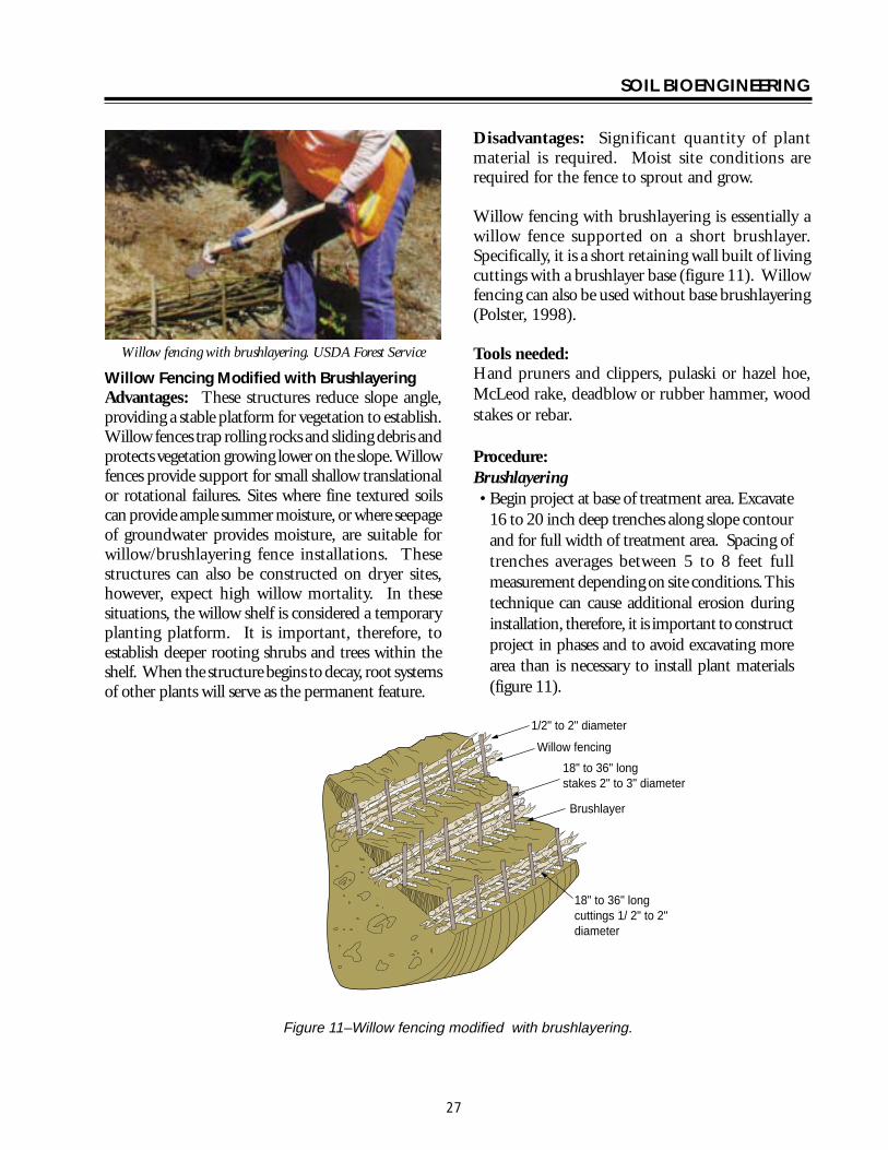
SOIL BIOENGINEERING
Willow fencing with brushlayering USDA Forest Service
Willow Fencing Modified with Brushlayering Advantages These structures reduce slope angle providing a stable platform for vegetation to establish Willow fences trap rolling rocks and sliding debris and protects vegetation growing lower on the slope Willow fences provide support for small shallow translational or rotational failures Sites where fine textured soils can provide ample summer moisture or where seepage of groundwater provides moisture are suitable for willowbrushlayering fence installations These structures can also be constructed on dryer sites however expect high willow mortality In these situations the willow shelf is considered a temporary planting platform It is important therefore to establish deeper rooting shrubs and trees within the shelf When the structure begins to decay root systems of other plants will serve as the permanent feature
Disadvantages Significant quantity of plant material is required Moist site conditions are required for the fence to sprout and grow
Willow fencing with brushlayering is essentially a willow fence supported on a short brushlayer Specifically it is a short retaining wall built of living cuttings with a brushlayer base (figure 11) Willow fencing can also be used without base brushlayering (Polster 1998)
Tools needed Hand pruners and clippers pulaski or hazel hoe McLeod rake deadblow or rubber hammer wood stakes or rebar
Procedure Brushlayering bull Begin project at base of treatment area Excavate
16 to 20 inch deep trenches along slope contour and for full width of treatment area Spacing of trenches averages between 5 to 8 feet full measurement depending on site conditions This technique can cause additional erosion during installation therefore it is important to construct project in phases and to avoid excavating more area than is necessary to install plant materials (figure 11)
12 to 2 diameter
Willow fencing
18 to 36 long stakes 2 to 3 diameter
Brushlayer
18 to 36 long cuttings 1 2 to 2 diameter
Figure 11ndashWillow fencing modified with brushlayering
27
SOIL BIOENGINEERING
bull Lay live brush stems along base of trench Length of stems average 16 inches in length and diameter of 12 to 2 inches Approximately 14 of average brush length should extend beyond slope face (figure 10)
Willow fencing bull Install supporting 18 to 36 inch long wood
stakes cuttings or rebar Average diameter of stakes ranges from 2 to 3 inches
bull Place a few shrub cuttings 18 to 36 inch long and 12 to 2-inch diameter cuttings behind these supports
bull Place enough soil behind these supports to hold the shrub cuttings in place
bull Stand in the trench and begin excavation of second row This process will allow soil from second trench to cover first willow fencing brushlayer row
bull Compact and slightly mound soil on brushlayer and behind willow fence
bull As more soil is added add additional cuttings until the final height of the fence is achieved A goal should be to construct a 21 slope or less between the top of the willow fence and the bottom of the one above
bull Move upslope to next trench alignment and repeat process (figure 11)
Branchpacking just after installation Robbin Sotir amp Associates
Branchpacking Advantages As plant tops grow branchpacking system becomes increasingly effective in retarding runoff and reducing surface erosion Trapped sediment refills localized slumps orholeswhile roots spreadthroughout the backfill and surrounding earth to form a unified mass (figure 12)
Disadvantage Not effective in slump areas greater than 4 feet deep or 5 feet wide
Branchpacking (Sotir and Gray 1992) consists of alternating layers of livebranch cuttings and compacted backfill to repair small localized slumps and holes (figure 12)
Tools needed Hand pruners and clippers deadblow or rubber hammer untreated twine McLeod rake shovel wood stakes
Branchpacking just after installation Robbin Sotir amp Associates
28
SOIL BIOENGINEERING
Branchpacking post installation Robbin Sotir amp Associates
Procedure bull Starting at lowest point drive wooden stakes
vertically 3 to 4 feet into the ground Set them 1- to 1 12 -feet apart Wooden stakes should be 5 to 8 feet long and made from 3-to-4 inch diameter poles or 2 by 4 lumber depending upon depth of particular slump or hole
bull Place a layer of live cut branches 4 to 6 inches thick in bottom of hole between vertical stakes and perpendicular to the slope face (figure 12) Crisscross branches with growing tips generally oriented toward slope face Some basal ends of branches should touch the back of the slope
bull Install subsequent layers with basal ends lower than the growing tips of the branches This is to insure developing root systems will be located at water collection points on the slope
bull Each layer of branches must be followed by a layer of compacted soil to ensure soil contact with branch cuttings
bull Final installation should match existing slope Branches should protrude only slightly from the filled face
bull The soil should be moist or moistened to insure live branches do not dry out
1 to 1-12
Live branch cuttings 14 to 2 diameter
Compact fill material
Wooden stakes 5 to 8 long 2 x 4 lumber driven 3 to 4 into undisturbed soil
4 to 6 inch layer of live branch cuttings laid criss cross and
touching back of hole
Live branch cuttings should protrude slightly from
backfill area
Several weeks or months later
spacing not to scale
Figure 12ndashBranchpacking
29
SOIL BIOENGINEERING
3 to 4 inch layer of live branch cuttings laid in crisscross and touching undisturbed soil on gully bed
Several weeks later
Live branch cuttings 1 to 2 in diameter
Compacted fill material 6 to 8 layer
Gully bed
Figure 13ndashLive gully repair
Live Gully Repair Advantages Offers immediate reinforcement to compacted soil reduces velocity of concentrated flow of water and provides a filter barrier to reduce rill and gully erosion
Disadvantages Limited to rills and gullies which are a maximum of 2-feet wide 1-foot deep and 15- feet long
Live gully repair (Sotir and Gray 1992) utilizes alternating layers of live branch cuttings and compacted soil to repair small rills and gullies Similar to branchpacking this method is more appropriate for repair of rills and gullies
Tools needed Hand pruners and clippers shovel McLeod rake untreated twine
Procedure bull Starting at lowest point of the slope place a 3shy
to 4-inch thick layer of live cut branches at lowest end of the rill or gully and perpendicular to the slope (figure 13)
bull Cover with 6-to 8-inch layer of soil
bull Install live cut branches in a crisscross fashion Orient growing tips toward slope face with basal ends lower than growing tips
bull Follow each layer of branches with a layer of compacted soil to ensure soil contact with live branch cuttings
30
SOIL BIOENGINEERING
Figure 14ndashVegetated geotextile
Vegetated Geotextile Advantages Retards rill and gully erosion stabilizes fill banks Is less expensive than other retaining walls such as gabion or Hilfiker baskets
Disadvantage Can be expensive if heavy equipment required
Synthetic or organic geotextile wrapped around lifts of soil with a mix of live branches placed between layers There are numerous opportunites of blending geotechnical-engineered systems with soil bioengineering The following is one example
Tools needed Backhoe geotextile hand pruners and clippers McLeod rake shovel untreated twine
Procedure bull Excavate lower edge of slope break and bench
backcut Compact the soil layer Note Structural integrity is dependent on compacted soil layers Even with mechanized firming soils support live cuttings
bull Lay first layer of geotextile down into the bench
bull Fill lowest lift with gravel fold back and stake securely
bull Fill subsequent layers with soil and layers of live cut branches (figure 10) and alternate with lifts (figure 14) Each layer must be compacted
bull The structure can be built with a vertical face or stair-stepped and sloped back into the hillside
31
SOIL BIOENGINEERING
Installation - cutslope stabilzation with log terracing USDA Forest Service
Log Terracing Advantages Logs create terraces reducing length and steepness of slope provides stable areas for establishment of other vegetation such as trees and shrubs
Disadvantages Labor intensive and with potential safety hazards
Tools needed Chainsaw PV pole blocks and cable power winch shackles and chokers pulaski Mcleod and shovel wood stakes hand pruner and clippers traffic control signs
Procedure bull The technique utilizes alternating terraced logs
to stop surface erosion on eroding slopes Stopping the erosion is critical for successful revegetation efforts Specifically log terracing shortens slope length and gradient between each structure providing stable planting areas throughout most of the slope face (figure 15)
bull Prior to beginning a log terracing project place traffic control signs several hundred feet on both sides of your project area Then climb slope to locate and remove potential safety hazards These hazards include loose tree root wads unstable rocks and boulders This inspection will also provide a different visual
perspective of the site This ldquotop-downrdquo viewpoint is usually the best place to formulate your project design
bull Begin log terracing at the base of the slope and work your way uphill This should prevent undercutting of any terrace or log you place above It also provides a stable and secure footing area for project work
bull Log terracing consists primarily of 3 main steps These steps include moving installing and anchoring logs to specified points on an eroding hillside
Moving bull Try not to cause any additional erosion or
damage log terraces you have already excavated This can be accomplished by setting up a skyline or carefully using a straight dragline with block and cable
Installation bull Use a minimum of 12-inch diameter logs
Sixteen or 20-inch diameter logs work best The most common error in log terracing is using logs that are too small in diameter
bull Use existing slope features such as tree stumps rock outcroppings or natural slope benches to secure one or both ends of the logs These natural features make project work easier safer and work better than stakes or rebar for keeping the log in place on the slope
bull Excavate terraces 13 the width of the log diameter deep and for full length of the log With rope (or cable) blocks and winch place the logs into position (figure 16)
Anchoring bull Depending on site conditions attempt to space
log terraces 10 to 20 feet apart
32
SOIL BIOENGINEERING
bull Anchor logs into the slope using 3-to 5-inch should be inserted into the ground Bend over diameter wood stakes or 34 inch rebar any excess rebar
bull Stake length should be 4 times the diameter of the log A 12-inch diameter log for example would require 48-inch long stakes and a 16shyinch diameter log 64-inch long stakes
bull Once in place drive stakes vertically into slope just below the log Two thirds of the stake should be driven into the ground These stakes should be spaced every 4 feet across the length of the log (figure 17) Another recommended technique is to drill holes through the log and anchor with rebar Two thirds of total length
bull When utilizing tree stumps and rock outcroppings for anchor points gaps may occur between log and soil surface This gap must be filled To do so excavate a trench uphill from the log and place a smaller log flush with the log structure (figure 17)
bull There are many possible patterns for log terracing The following 3 have proved useful for stabilization efforts (figure 15) Whatever pattern utilized it is absolutely critical no gaps exist between the log and soil surface
Erosion site Erosion site Erosion site
Retaining structure Retaining structure Retaining structure
15-20
15-20
Shortened slope distance 50 failure
width
Rock
20
Treestump
Staggered Pattern Ladder Pattern Building Block Pattern
not to scale
Figure 15ndashLog terrace installation
33
SOIL BIOENGINEERING
Staggered Using logs with lengths greater than 50 percent of the width of the erosion site These logs should overlap each other and be anchored into stable soils on either side of the failure site
Ladder Logs extend across full width of erosion site and should be anchored into stable soils on either side of failure site
Building block This method best mimics what happens naturally on an eroding slope Begin the project at the slope base This area is stable and will provide a secure base to build off of as you work your way up slope There is no set pattern Design and log placement pattern will evolve as the project progresses Be creative
bull Once the slope has been stabilized with log terracing it is critical to address the upper portion of the slope failure This area is often referred to as the slope overhang Addressing this area is critical since it is the source of the surface erosion Without removing this erosion source project success is unlikely Cut away the overhang so slope angle will allow seed to germinate and plants to establish Try to angle the slope to blend with the new slope gradient created with log terracing Often this will require a cut 5 to 6 feet upslope This is the most difficult portion of a log terracing project and will often result in removing vegetation This vegetation however can be transplanted to other areas on the slope
34
SOIL BIOENGINEERING
Use of existing slope features
Stump
Rock
Front view trench construction
Trench
Place log 13 of diameter deep
Slope
Place log 13 of diameter deep
Trench construction side view
Stakes
not to scale
Figure 16ndashLog terrace construction
Formula A 12 diameter log needs 48 long stakes
Trench
Stake 13 above
Stake 23 below
Stakes
Front view
Erosion site
Log
Cutslope
Roadbed
Vertical placement
Side view
Erosion site
Stake 13 above ground
Stake 23 below ground
Ground level
Gap
Ground level
Filler log
not to scale
Figure 17ndashAnchoring and filling gaps
35
SOIL BIOENGINEERING
Roadbed Ditch
Cutslope
Fill slope
Slope overhang
Slope overhang
Area to remove
Area to remove
not to scale
Figure 18ndashRemoval of slope overhang
36
SOIL BIOENGINEERING
Bender Board Fencing Advantages These structures reduce slope angle providing a stable platform for vegetation to establish Like willow fencing bender board structures trap rolling rocks and sliding debris and protects vegetation growing lower on the slope Bender board fences provide support for small translational or rotational failures
Dry sites where soils receive very little precipitation this type of structure The bender board shelf is considered a temporary planting platform It is important therefore to establish deeper rooting shrubs and trees within the shelves When the structures begins to decay root systems of other plants will serve as the permanent feature
Disadvantage Significant quantity of plant material is required
Redwood or cedar bender board fencing is essentially a fence supported on a short layer of shrub or tree stems Specifically it is a short retaining wall built of redwood or cedar bender fencing with a stem layered base
Tools needed Hand pruners and clippers pulaski or hazel hoe McLeod rake deadblow or rubber hammer wood stakes
Procedure Stem Layered Base bull Begin project at base of treatment area Excavate a
24-inch deep terrace along slope contour and for full width of treatment area The back of the terrace should be dug with an approximate 70 degree angle To allow ample planting platforms space terraces about 5 feet apart
bull Lay 2 feet 6-inch long stems and 2 feet 6-inch long wood stakes (5050 mix) 2-inches apart and for full length of terrace Diameter can range from 12 to 2-inches Approximatly 6-inches will extend beyond slope face
Bender board Fencing bull Drive supporting 4 foot 6-inch (2 by 2) long stakes
2 to 3 feet into ground spaced 1 foot apart and perpendicular to the slope Rebar may be used instead of wooden stakes
bull Weave 10 foot long bender boards through these stakes until the wall reaches a height of 2 feet Once complete the bender board fence wall should be at a 15 degree angle to the slope Note As shown in photo some bender board are too brittle to weave
bull Once the wall frame is constructed carefully rake enough soil into the terrace to cover the stem layered base
37
SOIL BIOENGINEERING
bull Stand in terrace and begin excavation of second bull Move upslope to next terrace alignment and row This process will allow soil into the terrace repeat process to cover the stem layered base
bull A goal should be to construct a 21 slope or less between the top of the bender board fence wall and the bottom of the one above
10 foot long bender boards 14 thick 3-12 wide
2-6 long stakes spaced 3 apart
2 high seven bender boards
2 wide terraces spaced 5 apart
not to scale
4-6 post buried 2-3
Figure 19ndashBender board fencing
38
SOIL BIOENGINEERING
REFERENCES CITED
Bach David H and MacAskill IA 1984 Vegetation and Landscape Engineering Granada London
Bennett Francis W 1975 Methods of Quickly Vegetating Soils of Low Productivity Construction Activities US Environmental Protection Agency Washington DC
Brosius Myra 1985 ldquoThe Restoration of an Urban Stream Using Geomorphic Relationships and Biotechnical Streambank Stabilizationrdquo Athens GA University of Georgia Thesis
Chandler RJ 1991 Slope Stability Engineering Institution of Civil Engineers Thomas Telford Publishing Company
Chatwin S D Howes and D Swantson 1994 A Guide for Management of Landslide Prone Terrain in the Pacific Northwest Second edition Ministry of Forests Crown Publications Victoria BC
Christensen M and J Jacobovitch 1992 Revegetation Projects Everything You Wanted to Know About Live Staking Unpublished report for King County Dept of Public Works Surface Water Management Div Seattle WA
Coppin NJ and IG Richards 1990 Use of Vegetation in Civil Engineering Butterworths London England
Coppin Nick J and R Stiles 1989 The Use of Vegetation in Slope Stabilization Landscape Design with Plants Second Edition ed by Brian Clouston Boca Raton Florida CRC Press 212-234
Edlin HL 1949 Woodland Crafts in Britain BT London Batsford Ltd London
Finney Kevin P 1993 BioEngineering Solutions A Tool for Education Eugene OR University of Oregon Thesis
Finney K 1993 History of Soil Bioengineering Eugene OR Masters Thesis University of Oregon Thesis
Gray DR and AT Leiser 1982 Biotechnical Slope Protection and Erosion Control New YorkVan Nostrand Reinhold Company New York
Gray DH Leiser T Andrew and C A White 1980 Combined Vegetative Structural Slope Stabilization Civil Engineering 50(1)82-85
Gray D R and Sotir RB 1996 Biotechnical and Soil Bioengineering Slope Stabilization John Wiley and Sons Inc
Greenway DR 1987 Vegetation and Slope Stability In Slope Stability John Wiley and Sons Ltd Chapter 6
41
SOIL BIOENGINEERING
Johnson AW and JM Stypula eds 1993 Guidelines for Bank Stabilization Projects In the Rivetine Environments of King County County Department of Public Works Surface Water Management Division Seattle WA
Kraebel CJ 1936 Erosion Control on Mountain Roads USDA Circular No 380 Washington DC USDA
Kraebel CJ 1933 Willow Cuttings for Erosion Control Technical Note No 1 Berkely California USDA California Forest Experiment Station
Larson FE and WE Guse 1981 Propagating Deciduous and Evergreen Shrubs Trees and Vines with Stem Cuttings Pacific Northwest Coop Ext Pub PNW152
Leiser Andrew T J J Nussbaum Kay Burgess Paul Jack and W Thornhill 1974 Revegetation of Disturbed Soils in the Tahoe Basin California Department of Transportation Sacramento California
Lewis EA and LW Ogg 1993 Soil Bioengineering Project Descriptions Unpublished report for Olympic National Forest Hood Canal Hanger District
Leys Emil 1978 Wilhelm Hassenteufel 80 Years Old Garten und Landschaft in China Vol 4 Part 3 Cambridge The University Press
Maleike R and RL Hummel 1988 Planting Landscape Plants Wash State Univ Coop Ext Pub EB1505
Polster Environmental Services 1998 Soil Bioengineering for Forest Land Reclamation and Stabilization British Columbia Ministry of Forests
Robbin B Sotir amp Associates A Brief History of Soil Bioengineering Unpublished and undated manuscript
Schiechtl Hugo 1980 Bioengineering For Land Reclamation and Conservation Edmonton Canada The University of Alberta Press
Schiechtl H M and R Stern 1997 Ground Bioengineering Techniques for Slope Protection and Erosion Control Blackwell Science Publications ISBN 0-632-04061-0
Sotir RB and DH Gray 1992 Soil Bioengineering for Upland Slope Protection and Erosion Reduction Engineering Field Handbook Soil Conservation Service Chapter 18
Stiles Richard (172) 57-61 1988 Engineering with Vegetation Landscape Design (172) 57-61
Stiles Richard1991 Re-inventing the Wheel Landscape Design (203)
42
SOIL BIOENGINEERING
Weaver WE and MA Madej 1981 Erosion Control Techniques Used in Redwood National Park In Davies TRH and AJ Pearce eds Erosion and Sediment Transport in Pacific Rim Steeplands Washington DC Intrsquol Assoc Hydrological Sciences 640-654 IAHS-AISH Pub 132
Westmacott Richard 1985 The Rediscovered Arts of Twilling and Wattling Landscape Architecture 75(4)95-98
White Charles A and AL Frank S 1978 Demonstration of Erosion and Sediment Control Technology Lake Tahoe Region of California EPA-6002-78-208 Municipal Environmental Research Laboratory Office of Research and Development US Environmental Protection Agency Cincinnati Ohio
Ziemer RR 1981 Roots and the Stability of Forested Slopes In Davies TRH and AJ Pearce eds Erosion and Sediment Transport in Pacific Rim Steeplands
43
SOIL BIOENGINEERING
About the Authorhellip
Lisa Lewis graduated in 1987 from Fort Valley State University Fort Valley Georgia with a Bachelor of Science degree in Soil and Plant Sciences Lisa began her career with the Forest Service in August 1987 on the Hood Canal Ranger District She continued her career in the Pacific Northwest and since 1998 she has been a soil scientist with the National Riparian Service Team (NRST) As a member of the NRST Lisa provides training and technology transfer consulting and advisory services and program review for riparian restoration nationwide She specializes in road management issues and soil bioengineering techniques
Library Card
Lewis Lisa 2000 Soil bioengineeringmdashan alternative to roadside managementmdasha practical guide Technical Report 0077-1801-SDTDC San Dimas CA US Department of Agriculture Forest Service San Dimas Technology and Development Center 44 p
This publication provides field personnel with the basic merits of soil bioengineering concepts and gives examples of several techniques especially effective in stabilizing and revegetating upland roadside environments The information provided in this document is intended to stimulate additional interest for the reader to seek out and use these and other soil bioengineering applications
Soil bioengineering is the use of live plant materials and flexible engineering techniques to alleviate environmental problems such as destabilized and eroding slopes Unlike other technologies in which plants are chiefly an aesthetic component of the project in soil bioengineering systems plants are an important structural component
Keywords Soil bioengineering road management road maintenance restoration erosion native plant materials revegetation
Additional single copies of this document may be ordered from
USDA Forest Service San Dimas Technology and Development Center
ATTN Richard Martinez 444 E Bonita Avenue San Dimas CA 91773
Phone (909) 599-1267 x201 Fax (909) 592-2309
E-Mail rmartinezwo_sdtdcfsfedus FSNotes Richard MartinezWOUSDAFS
For additional technical information contact Lisa Lewis at the following address
USDA Forest Service National Riparian Service Team
3050 NE 3rd Street PO Box 550
Prineville OR 98854 Phone (541) 416-6788
E-Mail l3Lewisorblmgov
An electronic copy of this document is available on the Forest Servicersquos FSWeb
Intranet at httpfswebsdtdcwofsfedus
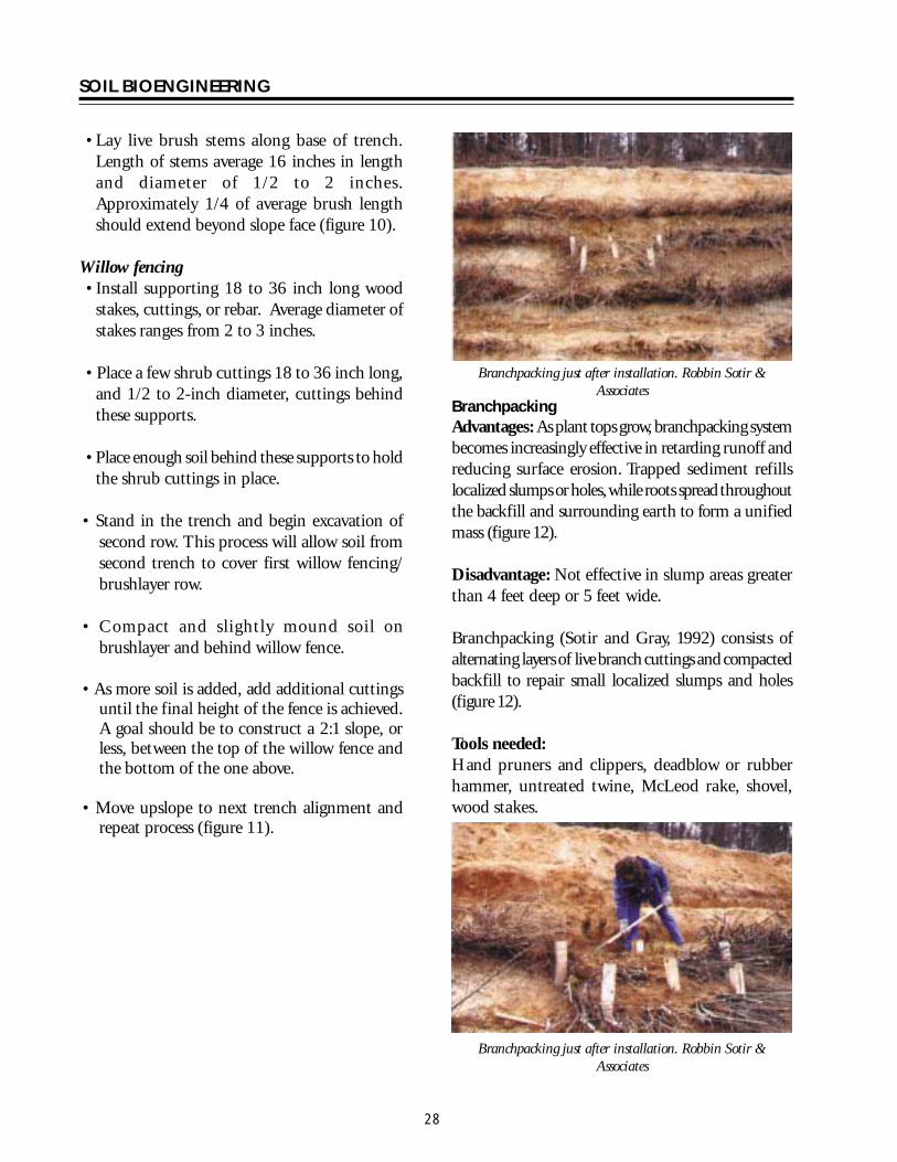
SOIL BIOENGINEERING
Branchpacking post installation Robbin Sotir amp Associates
Procedure bull Starting at lowest point drive wooden stakes
vertically 3 to 4 feet into the ground Set them 1- to 1 12 -feet apart Wooden stakes should be 5 to 8 feet long and made from 3-to-4 inch diameter poles or 2 by 4 lumber depending upon depth of particular slump or hole
bull Place a layer of live cut branches 4 to 6 inches thick in bottom of hole between vertical stakes and perpendicular to the slope face (figure 12) Crisscross branches with growing tips generally oriented toward slope face Some basal ends of branches should touch the back of the slope
bull Install subsequent layers with basal ends lower than the growing tips of the branches This is to insure developing root systems will be located at water collection points on the slope
bull Each layer of branches must be followed by a layer of compacted soil to ensure soil contact with branch cuttings
bull Final installation should match existing slope Branches should protrude only slightly from the filled face
bull The soil should be moist or moistened to insure live branches do not dry out
1 to 1-12
Live branch cuttings 14 to 2 diameter
Compact fill material
Wooden stakes 5 to 8 long 2 x 4 lumber driven 3 to 4 into undisturbed soil
4 to 6 inch layer of live branch cuttings laid criss cross and
touching back of hole
Live branch cuttings should protrude slightly from
backfill area
Several weeks or months later
spacing not to scale
Figure 12ndashBranchpacking
29
SOIL BIOENGINEERING
3 to 4 inch layer of live branch cuttings laid in crisscross and touching undisturbed soil on gully bed
Several weeks later
Live branch cuttings 1 to 2 in diameter
Compacted fill material 6 to 8 layer
Gully bed
Figure 13ndashLive gully repair
Live Gully Repair Advantages Offers immediate reinforcement to compacted soil reduces velocity of concentrated flow of water and provides a filter barrier to reduce rill and gully erosion
Disadvantages Limited to rills and gullies which are a maximum of 2-feet wide 1-foot deep and 15- feet long
Live gully repair (Sotir and Gray 1992) utilizes alternating layers of live branch cuttings and compacted soil to repair small rills and gullies Similar to branchpacking this method is more appropriate for repair of rills and gullies
Tools needed Hand pruners and clippers shovel McLeod rake untreated twine
Procedure bull Starting at lowest point of the slope place a 3shy
to 4-inch thick layer of live cut branches at lowest end of the rill or gully and perpendicular to the slope (figure 13)
bull Cover with 6-to 8-inch layer of soil
bull Install live cut branches in a crisscross fashion Orient growing tips toward slope face with basal ends lower than growing tips
bull Follow each layer of branches with a layer of compacted soil to ensure soil contact with live branch cuttings
30
SOIL BIOENGINEERING
Figure 14ndashVegetated geotextile
Vegetated Geotextile Advantages Retards rill and gully erosion stabilizes fill banks Is less expensive than other retaining walls such as gabion or Hilfiker baskets
Disadvantage Can be expensive if heavy equipment required
Synthetic or organic geotextile wrapped around lifts of soil with a mix of live branches placed between layers There are numerous opportunites of blending geotechnical-engineered systems with soil bioengineering The following is one example
Tools needed Backhoe geotextile hand pruners and clippers McLeod rake shovel untreated twine
Procedure bull Excavate lower edge of slope break and bench
backcut Compact the soil layer Note Structural integrity is dependent on compacted soil layers Even with mechanized firming soils support live cuttings
bull Lay first layer of geotextile down into the bench
bull Fill lowest lift with gravel fold back and stake securely
bull Fill subsequent layers with soil and layers of live cut branches (figure 10) and alternate with lifts (figure 14) Each layer must be compacted
bull The structure can be built with a vertical face or stair-stepped and sloped back into the hillside
31
SOIL BIOENGINEERING
Installation - cutslope stabilzation with log terracing USDA Forest Service
Log Terracing Advantages Logs create terraces reducing length and steepness of slope provides stable areas for establishment of other vegetation such as trees and shrubs
Disadvantages Labor intensive and with potential safety hazards
Tools needed Chainsaw PV pole blocks and cable power winch shackles and chokers pulaski Mcleod and shovel wood stakes hand pruner and clippers traffic control signs
Procedure bull The technique utilizes alternating terraced logs
to stop surface erosion on eroding slopes Stopping the erosion is critical for successful revegetation efforts Specifically log terracing shortens slope length and gradient between each structure providing stable planting areas throughout most of the slope face (figure 15)
bull Prior to beginning a log terracing project place traffic control signs several hundred feet on both sides of your project area Then climb slope to locate and remove potential safety hazards These hazards include loose tree root wads unstable rocks and boulders This inspection will also provide a different visual
perspective of the site This ldquotop-downrdquo viewpoint is usually the best place to formulate your project design
bull Begin log terracing at the base of the slope and work your way uphill This should prevent undercutting of any terrace or log you place above It also provides a stable and secure footing area for project work
bull Log terracing consists primarily of 3 main steps These steps include moving installing and anchoring logs to specified points on an eroding hillside
Moving bull Try not to cause any additional erosion or
damage log terraces you have already excavated This can be accomplished by setting up a skyline or carefully using a straight dragline with block and cable
Installation bull Use a minimum of 12-inch diameter logs
Sixteen or 20-inch diameter logs work best The most common error in log terracing is using logs that are too small in diameter
bull Use existing slope features such as tree stumps rock outcroppings or natural slope benches to secure one or both ends of the logs These natural features make project work easier safer and work better than stakes or rebar for keeping the log in place on the slope
bull Excavate terraces 13 the width of the log diameter deep and for full length of the log With rope (or cable) blocks and winch place the logs into position (figure 16)
Anchoring bull Depending on site conditions attempt to space
log terraces 10 to 20 feet apart
32
SOIL BIOENGINEERING
bull Anchor logs into the slope using 3-to 5-inch should be inserted into the ground Bend over diameter wood stakes or 34 inch rebar any excess rebar
bull Stake length should be 4 times the diameter of the log A 12-inch diameter log for example would require 48-inch long stakes and a 16shyinch diameter log 64-inch long stakes
bull Once in place drive stakes vertically into slope just below the log Two thirds of the stake should be driven into the ground These stakes should be spaced every 4 feet across the length of the log (figure 17) Another recommended technique is to drill holes through the log and anchor with rebar Two thirds of total length
bull When utilizing tree stumps and rock outcroppings for anchor points gaps may occur between log and soil surface This gap must be filled To do so excavate a trench uphill from the log and place a smaller log flush with the log structure (figure 17)
bull There are many possible patterns for log terracing The following 3 have proved useful for stabilization efforts (figure 15) Whatever pattern utilized it is absolutely critical no gaps exist between the log and soil surface
Erosion site Erosion site Erosion site
Retaining structure Retaining structure Retaining structure
15-20
15-20
Shortened slope distance 50 failure
width
Rock
20
Treestump
Staggered Pattern Ladder Pattern Building Block Pattern
not to scale
Figure 15ndashLog terrace installation
33
SOIL BIOENGINEERING
Staggered Using logs with lengths greater than 50 percent of the width of the erosion site These logs should overlap each other and be anchored into stable soils on either side of the failure site
Ladder Logs extend across full width of erosion site and should be anchored into stable soils on either side of failure site
Building block This method best mimics what happens naturally on an eroding slope Begin the project at the slope base This area is stable and will provide a secure base to build off of as you work your way up slope There is no set pattern Design and log placement pattern will evolve as the project progresses Be creative
bull Once the slope has been stabilized with log terracing it is critical to address the upper portion of the slope failure This area is often referred to as the slope overhang Addressing this area is critical since it is the source of the surface erosion Without removing this erosion source project success is unlikely Cut away the overhang so slope angle will allow seed to germinate and plants to establish Try to angle the slope to blend with the new slope gradient created with log terracing Often this will require a cut 5 to 6 feet upslope This is the most difficult portion of a log terracing project and will often result in removing vegetation This vegetation however can be transplanted to other areas on the slope
34
SOIL BIOENGINEERING
Use of existing slope features
Stump
Rock
Front view trench construction
Trench
Place log 13 of diameter deep
Slope
Place log 13 of diameter deep
Trench construction side view
Stakes
not to scale
Figure 16ndashLog terrace construction
Formula A 12 diameter log needs 48 long stakes
Trench
Stake 13 above
Stake 23 below
Stakes
Front view
Erosion site
Log
Cutslope
Roadbed
Vertical placement
Side view
Erosion site
Stake 13 above ground
Stake 23 below ground
Ground level
Gap
Ground level
Filler log
not to scale
Figure 17ndashAnchoring and filling gaps
35
SOIL BIOENGINEERING
Roadbed Ditch
Cutslope
Fill slope
Slope overhang
Slope overhang
Area to remove
Area to remove
not to scale
Figure 18ndashRemoval of slope overhang
36
SOIL BIOENGINEERING
Bender Board Fencing Advantages These structures reduce slope angle providing a stable platform for vegetation to establish Like willow fencing bender board structures trap rolling rocks and sliding debris and protects vegetation growing lower on the slope Bender board fences provide support for small translational or rotational failures
Dry sites where soils receive very little precipitation this type of structure The bender board shelf is considered a temporary planting platform It is important therefore to establish deeper rooting shrubs and trees within the shelves When the structures begins to decay root systems of other plants will serve as the permanent feature
Disadvantage Significant quantity of plant material is required
Redwood or cedar bender board fencing is essentially a fence supported on a short layer of shrub or tree stems Specifically it is a short retaining wall built of redwood or cedar bender fencing with a stem layered base
Tools needed Hand pruners and clippers pulaski or hazel hoe McLeod rake deadblow or rubber hammer wood stakes
Procedure Stem Layered Base bull Begin project at base of treatment area Excavate a
24-inch deep terrace along slope contour and for full width of treatment area The back of the terrace should be dug with an approximate 70 degree angle To allow ample planting platforms space terraces about 5 feet apart
bull Lay 2 feet 6-inch long stems and 2 feet 6-inch long wood stakes (5050 mix) 2-inches apart and for full length of terrace Diameter can range from 12 to 2-inches Approximatly 6-inches will extend beyond slope face
Bender board Fencing bull Drive supporting 4 foot 6-inch (2 by 2) long stakes
2 to 3 feet into ground spaced 1 foot apart and perpendicular to the slope Rebar may be used instead of wooden stakes
bull Weave 10 foot long bender boards through these stakes until the wall reaches a height of 2 feet Once complete the bender board fence wall should be at a 15 degree angle to the slope Note As shown in photo some bender board are too brittle to weave
bull Once the wall frame is constructed carefully rake enough soil into the terrace to cover the stem layered base
37
SOIL BIOENGINEERING
bull Stand in terrace and begin excavation of second bull Move upslope to next terrace alignment and row This process will allow soil into the terrace repeat process to cover the stem layered base
bull A goal should be to construct a 21 slope or less between the top of the bender board fence wall and the bottom of the one above
10 foot long bender boards 14 thick 3-12 wide
2-6 long stakes spaced 3 apart
2 high seven bender boards
2 wide terraces spaced 5 apart
not to scale
4-6 post buried 2-3
Figure 19ndashBender board fencing
38
SOIL BIOENGINEERING
REFERENCES CITED
Bach David H and MacAskill IA 1984 Vegetation and Landscape Engineering Granada London
Bennett Francis W 1975 Methods of Quickly Vegetating Soils of Low Productivity Construction Activities US Environmental Protection Agency Washington DC
Brosius Myra 1985 ldquoThe Restoration of an Urban Stream Using Geomorphic Relationships and Biotechnical Streambank Stabilizationrdquo Athens GA University of Georgia Thesis
Chandler RJ 1991 Slope Stability Engineering Institution of Civil Engineers Thomas Telford Publishing Company
Chatwin S D Howes and D Swantson 1994 A Guide for Management of Landslide Prone Terrain in the Pacific Northwest Second edition Ministry of Forests Crown Publications Victoria BC
Christensen M and J Jacobovitch 1992 Revegetation Projects Everything You Wanted to Know About Live Staking Unpublished report for King County Dept of Public Works Surface Water Management Div Seattle WA
Coppin NJ and IG Richards 1990 Use of Vegetation in Civil Engineering Butterworths London England
Coppin Nick J and R Stiles 1989 The Use of Vegetation in Slope Stabilization Landscape Design with Plants Second Edition ed by Brian Clouston Boca Raton Florida CRC Press 212-234
Edlin HL 1949 Woodland Crafts in Britain BT London Batsford Ltd London
Finney Kevin P 1993 BioEngineering Solutions A Tool for Education Eugene OR University of Oregon Thesis
Finney K 1993 History of Soil Bioengineering Eugene OR Masters Thesis University of Oregon Thesis
Gray DR and AT Leiser 1982 Biotechnical Slope Protection and Erosion Control New YorkVan Nostrand Reinhold Company New York
Gray DH Leiser T Andrew and C A White 1980 Combined Vegetative Structural Slope Stabilization Civil Engineering 50(1)82-85
Gray D R and Sotir RB 1996 Biotechnical and Soil Bioengineering Slope Stabilization John Wiley and Sons Inc
Greenway DR 1987 Vegetation and Slope Stability In Slope Stability John Wiley and Sons Ltd Chapter 6
41
SOIL BIOENGINEERING
Johnson AW and JM Stypula eds 1993 Guidelines for Bank Stabilization Projects In the Rivetine Environments of King County County Department of Public Works Surface Water Management Division Seattle WA
Kraebel CJ 1936 Erosion Control on Mountain Roads USDA Circular No 380 Washington DC USDA
Kraebel CJ 1933 Willow Cuttings for Erosion Control Technical Note No 1 Berkely California USDA California Forest Experiment Station
Larson FE and WE Guse 1981 Propagating Deciduous and Evergreen Shrubs Trees and Vines with Stem Cuttings Pacific Northwest Coop Ext Pub PNW152
Leiser Andrew T J J Nussbaum Kay Burgess Paul Jack and W Thornhill 1974 Revegetation of Disturbed Soils in the Tahoe Basin California Department of Transportation Sacramento California
Lewis EA and LW Ogg 1993 Soil Bioengineering Project Descriptions Unpublished report for Olympic National Forest Hood Canal Hanger District
Leys Emil 1978 Wilhelm Hassenteufel 80 Years Old Garten und Landschaft in China Vol 4 Part 3 Cambridge The University Press
Maleike R and RL Hummel 1988 Planting Landscape Plants Wash State Univ Coop Ext Pub EB1505
Polster Environmental Services 1998 Soil Bioengineering for Forest Land Reclamation and Stabilization British Columbia Ministry of Forests
Robbin B Sotir amp Associates A Brief History of Soil Bioengineering Unpublished and undated manuscript
Schiechtl Hugo 1980 Bioengineering For Land Reclamation and Conservation Edmonton Canada The University of Alberta Press
Schiechtl H M and R Stern 1997 Ground Bioengineering Techniques for Slope Protection and Erosion Control Blackwell Science Publications ISBN 0-632-04061-0
Sotir RB and DH Gray 1992 Soil Bioengineering for Upland Slope Protection and Erosion Reduction Engineering Field Handbook Soil Conservation Service Chapter 18
Stiles Richard (172) 57-61 1988 Engineering with Vegetation Landscape Design (172) 57-61
Stiles Richard1991 Re-inventing the Wheel Landscape Design (203)
42
SOIL BIOENGINEERING
Weaver WE and MA Madej 1981 Erosion Control Techniques Used in Redwood National Park In Davies TRH and AJ Pearce eds Erosion and Sediment Transport in Pacific Rim Steeplands Washington DC Intrsquol Assoc Hydrological Sciences 640-654 IAHS-AISH Pub 132
Westmacott Richard 1985 The Rediscovered Arts of Twilling and Wattling Landscape Architecture 75(4)95-98
White Charles A and AL Frank S 1978 Demonstration of Erosion and Sediment Control Technology Lake Tahoe Region of California EPA-6002-78-208 Municipal Environmental Research Laboratory Office of Research and Development US Environmental Protection Agency Cincinnati Ohio
Ziemer RR 1981 Roots and the Stability of Forested Slopes In Davies TRH and AJ Pearce eds Erosion and Sediment Transport in Pacific Rim Steeplands
43
SOIL BIOENGINEERING
About the Authorhellip
Lisa Lewis graduated in 1987 from Fort Valley State University Fort Valley Georgia with a Bachelor of Science degree in Soil and Plant Sciences Lisa began her career with the Forest Service in August 1987 on the Hood Canal Ranger District She continued her career in the Pacific Northwest and since 1998 she has been a soil scientist with the National Riparian Service Team (NRST) As a member of the NRST Lisa provides training and technology transfer consulting and advisory services and program review for riparian restoration nationwide She specializes in road management issues and soil bioengineering techniques
Library Card
Lewis Lisa 2000 Soil bioengineeringmdashan alternative to roadside managementmdasha practical guide Technical Report 0077-1801-SDTDC San Dimas CA US Department of Agriculture Forest Service San Dimas Technology and Development Center 44 p
This publication provides field personnel with the basic merits of soil bioengineering concepts and gives examples of several techniques especially effective in stabilizing and revegetating upland roadside environments The information provided in this document is intended to stimulate additional interest for the reader to seek out and use these and other soil bioengineering applications
Soil bioengineering is the use of live plant materials and flexible engineering techniques to alleviate environmental problems such as destabilized and eroding slopes Unlike other technologies in which plants are chiefly an aesthetic component of the project in soil bioengineering systems plants are an important structural component
Keywords Soil bioengineering road management road maintenance restoration erosion native plant materials revegetation
Additional single copies of this document may be ordered from
USDA Forest Service San Dimas Technology and Development Center
ATTN Richard Martinez 444 E Bonita Avenue San Dimas CA 91773
Phone (909) 599-1267 x201 Fax (909) 592-2309
E-Mail rmartinezwo_sdtdcfsfedus FSNotes Richard MartinezWOUSDAFS
For additional technical information contact Lisa Lewis at the following address
USDA Forest Service National Riparian Service Team
3050 NE 3rd Street PO Box 550
Prineville OR 98854 Phone (541) 416-6788
E-Mail l3Lewisorblmgov
An electronic copy of this document is available on the Forest Servicersquos FSWeb
Intranet at httpfswebsdtdcwofsfedus
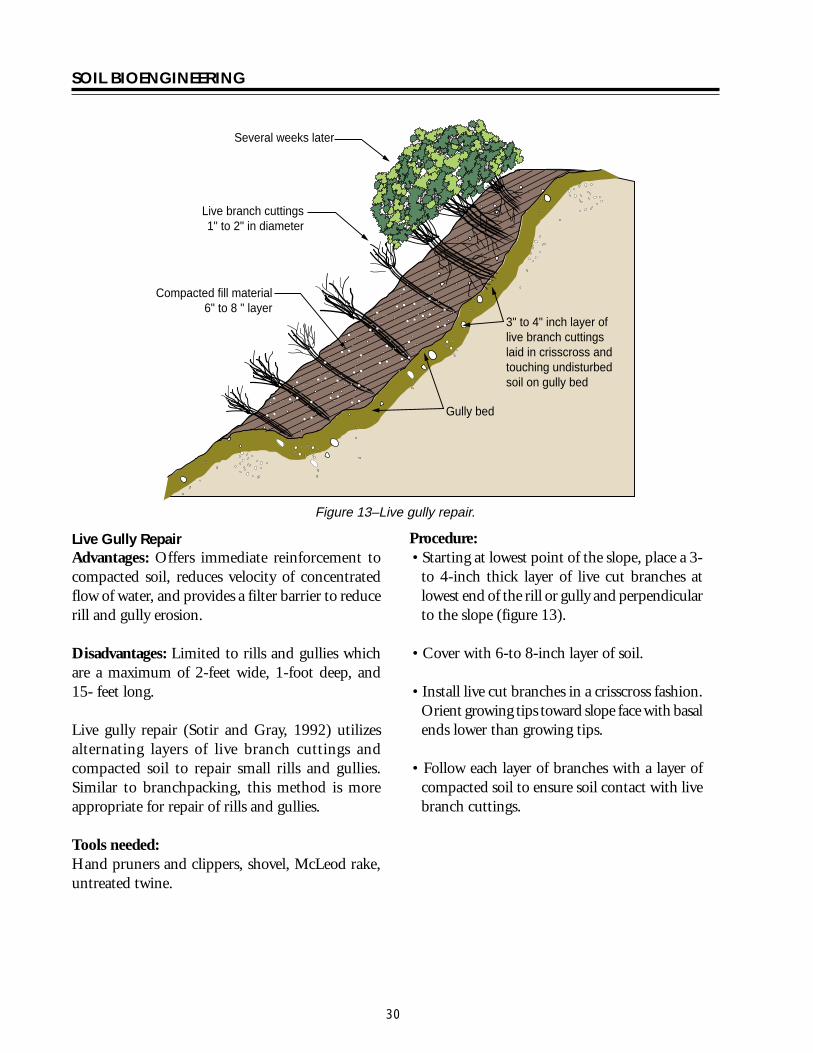
SOIL BIOENGINEERING
bull Anchor logs into the slope using 3-to 5-inch should be inserted into the ground Bend over diameter wood stakes or 34 inch rebar any excess rebar
bull Stake length should be 4 times the diameter of the log A 12-inch diameter log for example would require 48-inch long stakes and a 16shyinch diameter log 64-inch long stakes
bull Once in place drive stakes vertically into slope just below the log Two thirds of the stake should be driven into the ground These stakes should be spaced every 4 feet across the length of the log (figure 17) Another recommended technique is to drill holes through the log and anchor with rebar Two thirds of total length
bull When utilizing tree stumps and rock outcroppings for anchor points gaps may occur between log and soil surface This gap must be filled To do so excavate a trench uphill from the log and place a smaller log flush with the log structure (figure 17)
bull There are many possible patterns for log terracing The following 3 have proved useful for stabilization efforts (figure 15) Whatever pattern utilized it is absolutely critical no gaps exist between the log and soil surface
Erosion site Erosion site Erosion site
Retaining structure Retaining structure Retaining structure
15-20
15-20
Shortened slope distance 50 failure
width
Rock
20
Treestump
Staggered Pattern Ladder Pattern Building Block Pattern
not to scale
Figure 15ndashLog terrace installation
33
SOIL BIOENGINEERING
Staggered Using logs with lengths greater than 50 percent of the width of the erosion site These logs should overlap each other and be anchored into stable soils on either side of the failure site
Ladder Logs extend across full width of erosion site and should be anchored into stable soils on either side of failure site
Building block This method best mimics what happens naturally on an eroding slope Begin the project at the slope base This area is stable and will provide a secure base to build off of as you work your way up slope There is no set pattern Design and log placement pattern will evolve as the project progresses Be creative
bull Once the slope has been stabilized with log terracing it is critical to address the upper portion of the slope failure This area is often referred to as the slope overhang Addressing this area is critical since it is the source of the surface erosion Without removing this erosion source project success is unlikely Cut away the overhang so slope angle will allow seed to germinate and plants to establish Try to angle the slope to blend with the new slope gradient created with log terracing Often this will require a cut 5 to 6 feet upslope This is the most difficult portion of a log terracing project and will often result in removing vegetation This vegetation however can be transplanted to other areas on the slope
34
SOIL BIOENGINEERING
Use of existing slope features
Stump
Rock
Front view trench construction
Trench
Place log 13 of diameter deep
Slope
Place log 13 of diameter deep
Trench construction side view
Stakes
not to scale
Figure 16ndashLog terrace construction
Formula A 12 diameter log needs 48 long stakes
Trench
Stake 13 above
Stake 23 below
Stakes
Front view
Erosion site
Log
Cutslope
Roadbed
Vertical placement
Side view
Erosion site
Stake 13 above ground
Stake 23 below ground
Ground level
Gap
Ground level
Filler log
not to scale
Figure 17ndashAnchoring and filling gaps
35
SOIL BIOENGINEERING
Roadbed Ditch
Cutslope
Fill slope
Slope overhang
Slope overhang
Area to remove
Area to remove
not to scale
Figure 18ndashRemoval of slope overhang
36
SOIL BIOENGINEERING
Bender Board Fencing Advantages These structures reduce slope angle providing a stable platform for vegetation to establish Like willow fencing bender board structures trap rolling rocks and sliding debris and protects vegetation growing lower on the slope Bender board fences provide support for small translational or rotational failures
Dry sites where soils receive very little precipitation this type of structure The bender board shelf is considered a temporary planting platform It is important therefore to establish deeper rooting shrubs and trees within the shelves When the structures begins to decay root systems of other plants will serve as the permanent feature
Disadvantage Significant quantity of plant material is required
Redwood or cedar bender board fencing is essentially a fence supported on a short layer of shrub or tree stems Specifically it is a short retaining wall built of redwood or cedar bender fencing with a stem layered base
Tools needed Hand pruners and clippers pulaski or hazel hoe McLeod rake deadblow or rubber hammer wood stakes
Procedure Stem Layered Base bull Begin project at base of treatment area Excavate a
24-inch deep terrace along slope contour and for full width of treatment area The back of the terrace should be dug with an approximate 70 degree angle To allow ample planting platforms space terraces about 5 feet apart
bull Lay 2 feet 6-inch long stems and 2 feet 6-inch long wood stakes (5050 mix) 2-inches apart and for full length of terrace Diameter can range from 12 to 2-inches Approximatly 6-inches will extend beyond slope face
Bender board Fencing bull Drive supporting 4 foot 6-inch (2 by 2) long stakes
2 to 3 feet into ground spaced 1 foot apart and perpendicular to the slope Rebar may be used instead of wooden stakes
bull Weave 10 foot long bender boards through these stakes until the wall reaches a height of 2 feet Once complete the bender board fence wall should be at a 15 degree angle to the slope Note As shown in photo some bender board are too brittle to weave
bull Once the wall frame is constructed carefully rake enough soil into the terrace to cover the stem layered base
37
SOIL BIOENGINEERING
bull Stand in terrace and begin excavation of second bull Move upslope to next terrace alignment and row This process will allow soil into the terrace repeat process to cover the stem layered base
bull A goal should be to construct a 21 slope or less between the top of the bender board fence wall and the bottom of the one above
10 foot long bender boards 14 thick 3-12 wide
2-6 long stakes spaced 3 apart
2 high seven bender boards
2 wide terraces spaced 5 apart
not to scale
4-6 post buried 2-3
Figure 19ndashBender board fencing
38
SOIL BIOENGINEERING
REFERENCES CITED
Bach David H and MacAskill IA 1984 Vegetation and Landscape Engineering Granada London
Bennett Francis W 1975 Methods of Quickly Vegetating Soils of Low Productivity Construction Activities US Environmental Protection Agency Washington DC
Brosius Myra 1985 ldquoThe Restoration of an Urban Stream Using Geomorphic Relationships and Biotechnical Streambank Stabilizationrdquo Athens GA University of Georgia Thesis
Chandler RJ 1991 Slope Stability Engineering Institution of Civil Engineers Thomas Telford Publishing Company
Chatwin S D Howes and D Swantson 1994 A Guide for Management of Landslide Prone Terrain in the Pacific Northwest Second edition Ministry of Forests Crown Publications Victoria BC
Christensen M and J Jacobovitch 1992 Revegetation Projects Everything You Wanted to Know About Live Staking Unpublished report for King County Dept of Public Works Surface Water Management Div Seattle WA
Coppin NJ and IG Richards 1990 Use of Vegetation in Civil Engineering Butterworths London England
Coppin Nick J and R Stiles 1989 The Use of Vegetation in Slope Stabilization Landscape Design with Plants Second Edition ed by Brian Clouston Boca Raton Florida CRC Press 212-234
Edlin HL 1949 Woodland Crafts in Britain BT London Batsford Ltd London
Finney Kevin P 1993 BioEngineering Solutions A Tool for Education Eugene OR University of Oregon Thesis
Finney K 1993 History of Soil Bioengineering Eugene OR Masters Thesis University of Oregon Thesis
Gray DR and AT Leiser 1982 Biotechnical Slope Protection and Erosion Control New YorkVan Nostrand Reinhold Company New York
Gray DH Leiser T Andrew and C A White 1980 Combined Vegetative Structural Slope Stabilization Civil Engineering 50(1)82-85
Gray D R and Sotir RB 1996 Biotechnical and Soil Bioengineering Slope Stabilization John Wiley and Sons Inc
Greenway DR 1987 Vegetation and Slope Stability In Slope Stability John Wiley and Sons Ltd Chapter 6
41
SOIL BIOENGINEERING
Johnson AW and JM Stypula eds 1993 Guidelines for Bank Stabilization Projects In the Rivetine Environments of King County County Department of Public Works Surface Water Management Division Seattle WA
Kraebel CJ 1936 Erosion Control on Mountain Roads USDA Circular No 380 Washington DC USDA
Kraebel CJ 1933 Willow Cuttings for Erosion Control Technical Note No 1 Berkely California USDA California Forest Experiment Station
Larson FE and WE Guse 1981 Propagating Deciduous and Evergreen Shrubs Trees and Vines with Stem Cuttings Pacific Northwest Coop Ext Pub PNW152
Leiser Andrew T J J Nussbaum Kay Burgess Paul Jack and W Thornhill 1974 Revegetation of Disturbed Soils in the Tahoe Basin California Department of Transportation Sacramento California
Lewis EA and LW Ogg 1993 Soil Bioengineering Project Descriptions Unpublished report for Olympic National Forest Hood Canal Hanger District
Leys Emil 1978 Wilhelm Hassenteufel 80 Years Old Garten und Landschaft in China Vol 4 Part 3 Cambridge The University Press
Maleike R and RL Hummel 1988 Planting Landscape Plants Wash State Univ Coop Ext Pub EB1505
Polster Environmental Services 1998 Soil Bioengineering for Forest Land Reclamation and Stabilization British Columbia Ministry of Forests
Robbin B Sotir amp Associates A Brief History of Soil Bioengineering Unpublished and undated manuscript
Schiechtl Hugo 1980 Bioengineering For Land Reclamation and Conservation Edmonton Canada The University of Alberta Press
Schiechtl H M and R Stern 1997 Ground Bioengineering Techniques for Slope Protection and Erosion Control Blackwell Science Publications ISBN 0-632-04061-0
Sotir RB and DH Gray 1992 Soil Bioengineering for Upland Slope Protection and Erosion Reduction Engineering Field Handbook Soil Conservation Service Chapter 18
Stiles Richard (172) 57-61 1988 Engineering with Vegetation Landscape Design (172) 57-61
Stiles Richard1991 Re-inventing the Wheel Landscape Design (203)
42
SOIL BIOENGINEERING
Weaver WE and MA Madej 1981 Erosion Control Techniques Used in Redwood National Park In Davies TRH and AJ Pearce eds Erosion and Sediment Transport in Pacific Rim Steeplands Washington DC Intrsquol Assoc Hydrological Sciences 640-654 IAHS-AISH Pub 132
Westmacott Richard 1985 The Rediscovered Arts of Twilling and Wattling Landscape Architecture 75(4)95-98
White Charles A and AL Frank S 1978 Demonstration of Erosion and Sediment Control Technology Lake Tahoe Region of California EPA-6002-78-208 Municipal Environmental Research Laboratory Office of Research and Development US Environmental Protection Agency Cincinnati Ohio
Ziemer RR 1981 Roots and the Stability of Forested Slopes In Davies TRH and AJ Pearce eds Erosion and Sediment Transport in Pacific Rim Steeplands
43
SOIL BIOENGINEERING
About the Authorhellip
Lisa Lewis graduated in 1987 from Fort Valley State University Fort Valley Georgia with a Bachelor of Science degree in Soil and Plant Sciences Lisa began her career with the Forest Service in August 1987 on the Hood Canal Ranger District She continued her career in the Pacific Northwest and since 1998 she has been a soil scientist with the National Riparian Service Team (NRST) As a member of the NRST Lisa provides training and technology transfer consulting and advisory services and program review for riparian restoration nationwide She specializes in road management issues and soil bioengineering techniques
Library Card
Lewis Lisa 2000 Soil bioengineeringmdashan alternative to roadside managementmdasha practical guide Technical Report 0077-1801-SDTDC San Dimas CA US Department of Agriculture Forest Service San Dimas Technology and Development Center 44 p
This publication provides field personnel with the basic merits of soil bioengineering concepts and gives examples of several techniques especially effective in stabilizing and revegetating upland roadside environments The information provided in this document is intended to stimulate additional interest for the reader to seek out and use these and other soil bioengineering applications
Soil bioengineering is the use of live plant materials and flexible engineering techniques to alleviate environmental problems such as destabilized and eroding slopes Unlike other technologies in which plants are chiefly an aesthetic component of the project in soil bioengineering systems plants are an important structural component
Keywords Soil bioengineering road management road maintenance restoration erosion native plant materials revegetation
Additional single copies of this document may be ordered from
USDA Forest Service San Dimas Technology and Development Center
ATTN Richard Martinez 444 E Bonita Avenue San Dimas CA 91773
Phone (909) 599-1267 x201 Fax (909) 592-2309
E-Mail rmartinezwo_sdtdcfsfedus FSNotes Richard MartinezWOUSDAFS
For additional technical information contact Lisa Lewis at the following address
USDA Forest Service National Riparian Service Team
3050 NE 3rd Street PO Box 550
Prineville OR 98854 Phone (541) 416-6788
E-Mail l3Lewisorblmgov
An electronic copy of this document is available on the Forest Servicersquos FSWeb
Intranet at httpfswebsdtdcwofsfedus
SOIL BIOENGINEERING
Staggered Using logs with lengths greater than 50 percent of the width of the erosion site These logs should overlap each other and be anchored into stable soils on either side of the failure site
Ladder Logs extend across full width of erosion site and should be anchored into stable soils on either side of failure site
Building block This method best mimics what happens naturally on an eroding slope Begin the project at the slope base This area is stable and will provide a secure base to build off of as you work your way up slope There is no set pattern Design and log placement pattern will evolve as the project progresses Be creative
bull Once the slope has been stabilized with log terracing it is critical to address the upper portion of the slope failure This area is often referred to as the slope overhang Addressing this area is critical since it is the source of the surface erosion Without removing this erosion source project success is unlikely Cut away the overhang so slope angle will allow seed to germinate and plants to establish Try to angle the slope to blend with the new slope gradient created with log terracing Often this will require a cut 5 to 6 feet upslope This is the most difficult portion of a log terracing project and will often result in removing vegetation This vegetation however can be transplanted to other areas on the slope
34
SOIL BIOENGINEERING
Use of existing slope features
Stump
Rock
Front view trench construction
Trench
Place log 13 of diameter deep
Slope
Place log 13 of diameter deep
Trench construction side view
Stakes
not to scale
Figure 16ndashLog terrace construction
Formula A 12 diameter log needs 48 long stakes
Trench
Stake 13 above
Stake 23 below
Stakes
Front view
Erosion site
Log
Cutslope
Roadbed
Vertical placement
Side view
Erosion site
Stake 13 above ground
Stake 23 below ground
Ground level
Gap
Ground level
Filler log
not to scale
Figure 17ndashAnchoring and filling gaps
35
SOIL BIOENGINEERING
Roadbed Ditch
Cutslope
Fill slope
Slope overhang
Slope overhang
Area to remove
Area to remove
not to scale
Figure 18ndashRemoval of slope overhang
36
SOIL BIOENGINEERING
Bender Board Fencing Advantages These structures reduce slope angle providing a stable platform for vegetation to establish Like willow fencing bender board structures trap rolling rocks and sliding debris and protects vegetation growing lower on the slope Bender board fences provide support for small translational or rotational failures
Dry sites where soils receive very little precipitation this type of structure The bender board shelf is considered a temporary planting platform It is important therefore to establish deeper rooting shrubs and trees within the shelves When the structures begins to decay root systems of other plants will serve as the permanent feature
Disadvantage Significant quantity of plant material is required
Redwood or cedar bender board fencing is essentially a fence supported on a short layer of shrub or tree stems Specifically it is a short retaining wall built of redwood or cedar bender fencing with a stem layered base
Tools needed Hand pruners and clippers pulaski or hazel hoe McLeod rake deadblow or rubber hammer wood stakes
Procedure Stem Layered Base bull Begin project at base of treatment area Excavate a
24-inch deep terrace along slope contour and for full width of treatment area The back of the terrace should be dug with an approximate 70 degree angle To allow ample planting platforms space terraces about 5 feet apart
bull Lay 2 feet 6-inch long stems and 2 feet 6-inch long wood stakes (5050 mix) 2-inches apart and for full length of terrace Diameter can range from 12 to 2-inches Approximatly 6-inches will extend beyond slope face
Bender board Fencing bull Drive supporting 4 foot 6-inch (2 by 2) long stakes
2 to 3 feet into ground spaced 1 foot apart and perpendicular to the slope Rebar may be used instead of wooden stakes
bull Weave 10 foot long bender boards through these stakes until the wall reaches a height of 2 feet Once complete the bender board fence wall should be at a 15 degree angle to the slope Note As shown in photo some bender board are too brittle to weave
bull Once the wall frame is constructed carefully rake enough soil into the terrace to cover the stem layered base
37
SOIL BIOENGINEERING
bull Stand in terrace and begin excavation of second bull Move upslope to next terrace alignment and row This process will allow soil into the terrace repeat process to cover the stem layered base
bull A goal should be to construct a 21 slope or less between the top of the bender board fence wall and the bottom of the one above
10 foot long bender boards 14 thick 3-12 wide
2-6 long stakes spaced 3 apart
2 high seven bender boards
2 wide terraces spaced 5 apart
not to scale
4-6 post buried 2-3
Figure 19ndashBender board fencing
38
SOIL BIOENGINEERING
REFERENCES CITED
Bach David H and MacAskill IA 1984 Vegetation and Landscape Engineering Granada London
Bennett Francis W 1975 Methods of Quickly Vegetating Soils of Low Productivity Construction Activities US Environmental Protection Agency Washington DC
Brosius Myra 1985 ldquoThe Restoration of an Urban Stream Using Geomorphic Relationships and Biotechnical Streambank Stabilizationrdquo Athens GA University of Georgia Thesis
Chandler RJ 1991 Slope Stability Engineering Institution of Civil Engineers Thomas Telford Publishing Company
Chatwin S D Howes and D Swantson 1994 A Guide for Management of Landslide Prone Terrain in the Pacific Northwest Second edition Ministry of Forests Crown Publications Victoria BC
Christensen M and J Jacobovitch 1992 Revegetation Projects Everything You Wanted to Know About Live Staking Unpublished report for King County Dept of Public Works Surface Water Management Div Seattle WA
Coppin NJ and IG Richards 1990 Use of Vegetation in Civil Engineering Butterworths London England
Coppin Nick J and R Stiles 1989 The Use of Vegetation in Slope Stabilization Landscape Design with Plants Second Edition ed by Brian Clouston Boca Raton Florida CRC Press 212-234
Edlin HL 1949 Woodland Crafts in Britain BT London Batsford Ltd London
Finney Kevin P 1993 BioEngineering Solutions A Tool for Education Eugene OR University of Oregon Thesis
Finney K 1993 History of Soil Bioengineering Eugene OR Masters Thesis University of Oregon Thesis
Gray DR and AT Leiser 1982 Biotechnical Slope Protection and Erosion Control New YorkVan Nostrand Reinhold Company New York
Gray DH Leiser T Andrew and C A White 1980 Combined Vegetative Structural Slope Stabilization Civil Engineering 50(1)82-85
Gray D R and Sotir RB 1996 Biotechnical and Soil Bioengineering Slope Stabilization John Wiley and Sons Inc
Greenway DR 1987 Vegetation and Slope Stability In Slope Stability John Wiley and Sons Ltd Chapter 6
41
SOIL BIOENGINEERING
Johnson AW and JM Stypula eds 1993 Guidelines for Bank Stabilization Projects In the Rivetine Environments of King County County Department of Public Works Surface Water Management Division Seattle WA
Kraebel CJ 1936 Erosion Control on Mountain Roads USDA Circular No 380 Washington DC USDA
Kraebel CJ 1933 Willow Cuttings for Erosion Control Technical Note No 1 Berkely California USDA California Forest Experiment Station
Larson FE and WE Guse 1981 Propagating Deciduous and Evergreen Shrubs Trees and Vines with Stem Cuttings Pacific Northwest Coop Ext Pub PNW152
Leiser Andrew T J J Nussbaum Kay Burgess Paul Jack and W Thornhill 1974 Revegetation of Disturbed Soils in the Tahoe Basin California Department of Transportation Sacramento California
Lewis EA and LW Ogg 1993 Soil Bioengineering Project Descriptions Unpublished report for Olympic National Forest Hood Canal Hanger District
Leys Emil 1978 Wilhelm Hassenteufel 80 Years Old Garten und Landschaft in China Vol 4 Part 3 Cambridge The University Press
Maleike R and RL Hummel 1988 Planting Landscape Plants Wash State Univ Coop Ext Pub EB1505
Polster Environmental Services 1998 Soil Bioengineering for Forest Land Reclamation and Stabilization British Columbia Ministry of Forests
Robbin B Sotir amp Associates A Brief History of Soil Bioengineering Unpublished and undated manuscript
Schiechtl Hugo 1980 Bioengineering For Land Reclamation and Conservation Edmonton Canada The University of Alberta Press
Schiechtl H M and R Stern 1997 Ground Bioengineering Techniques for Slope Protection and Erosion Control Blackwell Science Publications ISBN 0-632-04061-0
Sotir RB and DH Gray 1992 Soil Bioengineering for Upland Slope Protection and Erosion Reduction Engineering Field Handbook Soil Conservation Service Chapter 18
Stiles Richard (172) 57-61 1988 Engineering with Vegetation Landscape Design (172) 57-61
Stiles Richard1991 Re-inventing the Wheel Landscape Design (203)
42
SOIL BIOENGINEERING
Weaver WE and MA Madej 1981 Erosion Control Techniques Used in Redwood National Park In Davies TRH and AJ Pearce eds Erosion and Sediment Transport in Pacific Rim Steeplands Washington DC Intrsquol Assoc Hydrological Sciences 640-654 IAHS-AISH Pub 132
Westmacott Richard 1985 The Rediscovered Arts of Twilling and Wattling Landscape Architecture 75(4)95-98
White Charles A and AL Frank S 1978 Demonstration of Erosion and Sediment Control Technology Lake Tahoe Region of California EPA-6002-78-208 Municipal Environmental Research Laboratory Office of Research and Development US Environmental Protection Agency Cincinnati Ohio
Ziemer RR 1981 Roots and the Stability of Forested Slopes In Davies TRH and AJ Pearce eds Erosion and Sediment Transport in Pacific Rim Steeplands
43
SOIL BIOENGINEERING
About the Authorhellip
Lisa Lewis graduated in 1987 from Fort Valley State University Fort Valley Georgia with a Bachelor of Science degree in Soil and Plant Sciences Lisa began her career with the Forest Service in August 1987 on the Hood Canal Ranger District She continued her career in the Pacific Northwest and since 1998 she has been a soil scientist with the National Riparian Service Team (NRST) As a member of the NRST Lisa provides training and technology transfer consulting and advisory services and program review for riparian restoration nationwide She specializes in road management issues and soil bioengineering techniques
Library Card
Lewis Lisa 2000 Soil bioengineeringmdashan alternative to roadside managementmdasha practical guide Technical Report 0077-1801-SDTDC San Dimas CA US Department of Agriculture Forest Service San Dimas Technology and Development Center 44 p
This publication provides field personnel with the basic merits of soil bioengineering concepts and gives examples of several techniques especially effective in stabilizing and revegetating upland roadside environments The information provided in this document is intended to stimulate additional interest for the reader to seek out and use these and other soil bioengineering applications
Soil bioengineering is the use of live plant materials and flexible engineering techniques to alleviate environmental problems such as destabilized and eroding slopes Unlike other technologies in which plants are chiefly an aesthetic component of the project in soil bioengineering systems plants are an important structural component
Keywords Soil bioengineering road management road maintenance restoration erosion native plant materials revegetation
Additional single copies of this document may be ordered from
USDA Forest Service San Dimas Technology and Development Center
ATTN Richard Martinez 444 E Bonita Avenue San Dimas CA 91773
Phone (909) 599-1267 x201 Fax (909) 592-2309
E-Mail rmartinezwo_sdtdcfsfedus FSNotes Richard MartinezWOUSDAFS
For additional technical information contact Lisa Lewis at the following address
USDA Forest Service National Riparian Service Team
3050 NE 3rd Street PO Box 550
Prineville OR 98854 Phone (541) 416-6788
E-Mail l3Lewisorblmgov
An electronic copy of this document is available on the Forest Servicersquos FSWeb
Intranet at httpfswebsdtdcwofsfedus

SOIL BIOENGINEERING
Use of existing slope features
Stump
Rock
Front view trench construction
Trench
Place log 13 of diameter deep
Slope
Place log 13 of diameter deep
Trench construction side view
Stakes
not to scale
Figure 16ndashLog terrace construction
Formula A 12 diameter log needs 48 long stakes
Trench
Stake 13 above
Stake 23 below
Stakes
Front view
Erosion site
Log
Cutslope
Roadbed
Vertical placement
Side view
Erosion site
Stake 13 above ground
Stake 23 below ground
Ground level
Gap
Ground level
Filler log
not to scale
Figure 17ndashAnchoring and filling gaps
35
SOIL BIOENGINEERING
Roadbed Ditch
Cutslope
Fill slope
Slope overhang
Slope overhang
Area to remove
Area to remove
not to scale
Figure 18ndashRemoval of slope overhang
36
SOIL BIOENGINEERING
Bender Board Fencing Advantages These structures reduce slope angle providing a stable platform for vegetation to establish Like willow fencing bender board structures trap rolling rocks and sliding debris and protects vegetation growing lower on the slope Bender board fences provide support for small translational or rotational failures
Dry sites where soils receive very little precipitation this type of structure The bender board shelf is considered a temporary planting platform It is important therefore to establish deeper rooting shrubs and trees within the shelves When the structures begins to decay root systems of other plants will serve as the permanent feature
Disadvantage Significant quantity of plant material is required
Redwood or cedar bender board fencing is essentially a fence supported on a short layer of shrub or tree stems Specifically it is a short retaining wall built of redwood or cedar bender fencing with a stem layered base
Tools needed Hand pruners and clippers pulaski or hazel hoe McLeod rake deadblow or rubber hammer wood stakes
Procedure Stem Layered Base bull Begin project at base of treatment area Excavate a
24-inch deep terrace along slope contour and for full width of treatment area The back of the terrace should be dug with an approximate 70 degree angle To allow ample planting platforms space terraces about 5 feet apart
bull Lay 2 feet 6-inch long stems and 2 feet 6-inch long wood stakes (5050 mix) 2-inches apart and for full length of terrace Diameter can range from 12 to 2-inches Approximatly 6-inches will extend beyond slope face
Bender board Fencing bull Drive supporting 4 foot 6-inch (2 by 2) long stakes
2 to 3 feet into ground spaced 1 foot apart and perpendicular to the slope Rebar may be used instead of wooden stakes
bull Weave 10 foot long bender boards through these stakes until the wall reaches a height of 2 feet Once complete the bender board fence wall should be at a 15 degree angle to the slope Note As shown in photo some bender board are too brittle to weave
bull Once the wall frame is constructed carefully rake enough soil into the terrace to cover the stem layered base
37
SOIL BIOENGINEERING
bull Stand in terrace and begin excavation of second bull Move upslope to next terrace alignment and row This process will allow soil into the terrace repeat process to cover the stem layered base
bull A goal should be to construct a 21 slope or less between the top of the bender board fence wall and the bottom of the one above
10 foot long bender boards 14 thick 3-12 wide
2-6 long stakes spaced 3 apart
2 high seven bender boards
2 wide terraces spaced 5 apart
not to scale
4-6 post buried 2-3
Figure 19ndashBender board fencing
38
SOIL BIOENGINEERING
REFERENCES CITED
Bach David H and MacAskill IA 1984 Vegetation and Landscape Engineering Granada London
Bennett Francis W 1975 Methods of Quickly Vegetating Soils of Low Productivity Construction Activities US Environmental Protection Agency Washington DC
Brosius Myra 1985 ldquoThe Restoration of an Urban Stream Using Geomorphic Relationships and Biotechnical Streambank Stabilizationrdquo Athens GA University of Georgia Thesis
Chandler RJ 1991 Slope Stability Engineering Institution of Civil Engineers Thomas Telford Publishing Company
Chatwin S D Howes and D Swantson 1994 A Guide for Management of Landslide Prone Terrain in the Pacific Northwest Second edition Ministry of Forests Crown Publications Victoria BC
Christensen M and J Jacobovitch 1992 Revegetation Projects Everything You Wanted to Know About Live Staking Unpublished report for King County Dept of Public Works Surface Water Management Div Seattle WA
Coppin NJ and IG Richards 1990 Use of Vegetation in Civil Engineering Butterworths London England
Coppin Nick J and R Stiles 1989 The Use of Vegetation in Slope Stabilization Landscape Design with Plants Second Edition ed by Brian Clouston Boca Raton Florida CRC Press 212-234
Edlin HL 1949 Woodland Crafts in Britain BT London Batsford Ltd London
Finney Kevin P 1993 BioEngineering Solutions A Tool for Education Eugene OR University of Oregon Thesis
Finney K 1993 History of Soil Bioengineering Eugene OR Masters Thesis University of Oregon Thesis
Gray DR and AT Leiser 1982 Biotechnical Slope Protection and Erosion Control New YorkVan Nostrand Reinhold Company New York
Gray DH Leiser T Andrew and C A White 1980 Combined Vegetative Structural Slope Stabilization Civil Engineering 50(1)82-85
Gray D R and Sotir RB 1996 Biotechnical and Soil Bioengineering Slope Stabilization John Wiley and Sons Inc
Greenway DR 1987 Vegetation and Slope Stability In Slope Stability John Wiley and Sons Ltd Chapter 6
41
SOIL BIOENGINEERING
Johnson AW and JM Stypula eds 1993 Guidelines for Bank Stabilization Projects In the Rivetine Environments of King County County Department of Public Works Surface Water Management Division Seattle WA
Kraebel CJ 1936 Erosion Control on Mountain Roads USDA Circular No 380 Washington DC USDA
Kraebel CJ 1933 Willow Cuttings for Erosion Control Technical Note No 1 Berkely California USDA California Forest Experiment Station
Larson FE and WE Guse 1981 Propagating Deciduous and Evergreen Shrubs Trees and Vines with Stem Cuttings Pacific Northwest Coop Ext Pub PNW152
Leiser Andrew T J J Nussbaum Kay Burgess Paul Jack and W Thornhill 1974 Revegetation of Disturbed Soils in the Tahoe Basin California Department of Transportation Sacramento California
Lewis EA and LW Ogg 1993 Soil Bioengineering Project Descriptions Unpublished report for Olympic National Forest Hood Canal Hanger District
Leys Emil 1978 Wilhelm Hassenteufel 80 Years Old Garten und Landschaft in China Vol 4 Part 3 Cambridge The University Press
Maleike R and RL Hummel 1988 Planting Landscape Plants Wash State Univ Coop Ext Pub EB1505
Polster Environmental Services 1998 Soil Bioengineering for Forest Land Reclamation and Stabilization British Columbia Ministry of Forests
Robbin B Sotir amp Associates A Brief History of Soil Bioengineering Unpublished and undated manuscript
Schiechtl Hugo 1980 Bioengineering For Land Reclamation and Conservation Edmonton Canada The University of Alberta Press
Schiechtl H M and R Stern 1997 Ground Bioengineering Techniques for Slope Protection and Erosion Control Blackwell Science Publications ISBN 0-632-04061-0
Sotir RB and DH Gray 1992 Soil Bioengineering for Upland Slope Protection and Erosion Reduction Engineering Field Handbook Soil Conservation Service Chapter 18
Stiles Richard (172) 57-61 1988 Engineering with Vegetation Landscape Design (172) 57-61
Stiles Richard1991 Re-inventing the Wheel Landscape Design (203)
42
SOIL BIOENGINEERING
Weaver WE and MA Madej 1981 Erosion Control Techniques Used in Redwood National Park In Davies TRH and AJ Pearce eds Erosion and Sediment Transport in Pacific Rim Steeplands Washington DC Intrsquol Assoc Hydrological Sciences 640-654 IAHS-AISH Pub 132
Westmacott Richard 1985 The Rediscovered Arts of Twilling and Wattling Landscape Architecture 75(4)95-98
White Charles A and AL Frank S 1978 Demonstration of Erosion and Sediment Control Technology Lake Tahoe Region of California EPA-6002-78-208 Municipal Environmental Research Laboratory Office of Research and Development US Environmental Protection Agency Cincinnati Ohio
Ziemer RR 1981 Roots and the Stability of Forested Slopes In Davies TRH and AJ Pearce eds Erosion and Sediment Transport in Pacific Rim Steeplands
43
SOIL BIOENGINEERING
About the Authorhellip
Lisa Lewis graduated in 1987 from Fort Valley State University Fort Valley Georgia with a Bachelor of Science degree in Soil and Plant Sciences Lisa began her career with the Forest Service in August 1987 on the Hood Canal Ranger District She continued her career in the Pacific Northwest and since 1998 she has been a soil scientist with the National Riparian Service Team (NRST) As a member of the NRST Lisa provides training and technology transfer consulting and advisory services and program review for riparian restoration nationwide She specializes in road management issues and soil bioengineering techniques
Library Card
Lewis Lisa 2000 Soil bioengineeringmdashan alternative to roadside managementmdasha practical guide Technical Report 0077-1801-SDTDC San Dimas CA US Department of Agriculture Forest Service San Dimas Technology and Development Center 44 p
This publication provides field personnel with the basic merits of soil bioengineering concepts and gives examples of several techniques especially effective in stabilizing and revegetating upland roadside environments The information provided in this document is intended to stimulate additional interest for the reader to seek out and use these and other soil bioengineering applications
Soil bioengineering is the use of live plant materials and flexible engineering techniques to alleviate environmental problems such as destabilized and eroding slopes Unlike other technologies in which plants are chiefly an aesthetic component of the project in soil bioengineering systems plants are an important structural component
Keywords Soil bioengineering road management road maintenance restoration erosion native plant materials revegetation
Additional single copies of this document may be ordered from
USDA Forest Service San Dimas Technology and Development Center
ATTN Richard Martinez 444 E Bonita Avenue San Dimas CA 91773
Phone (909) 599-1267 x201 Fax (909) 592-2309
E-Mail rmartinezwo_sdtdcfsfedus FSNotes Richard MartinezWOUSDAFS
For additional technical information contact Lisa Lewis at the following address
USDA Forest Service National Riparian Service Team
3050 NE 3rd Street PO Box 550
Prineville OR 98854 Phone (541) 416-6788
E-Mail l3Lewisorblmgov
An electronic copy of this document is available on the Forest Servicersquos FSWeb
Intranet at httpfswebsdtdcwofsfedus
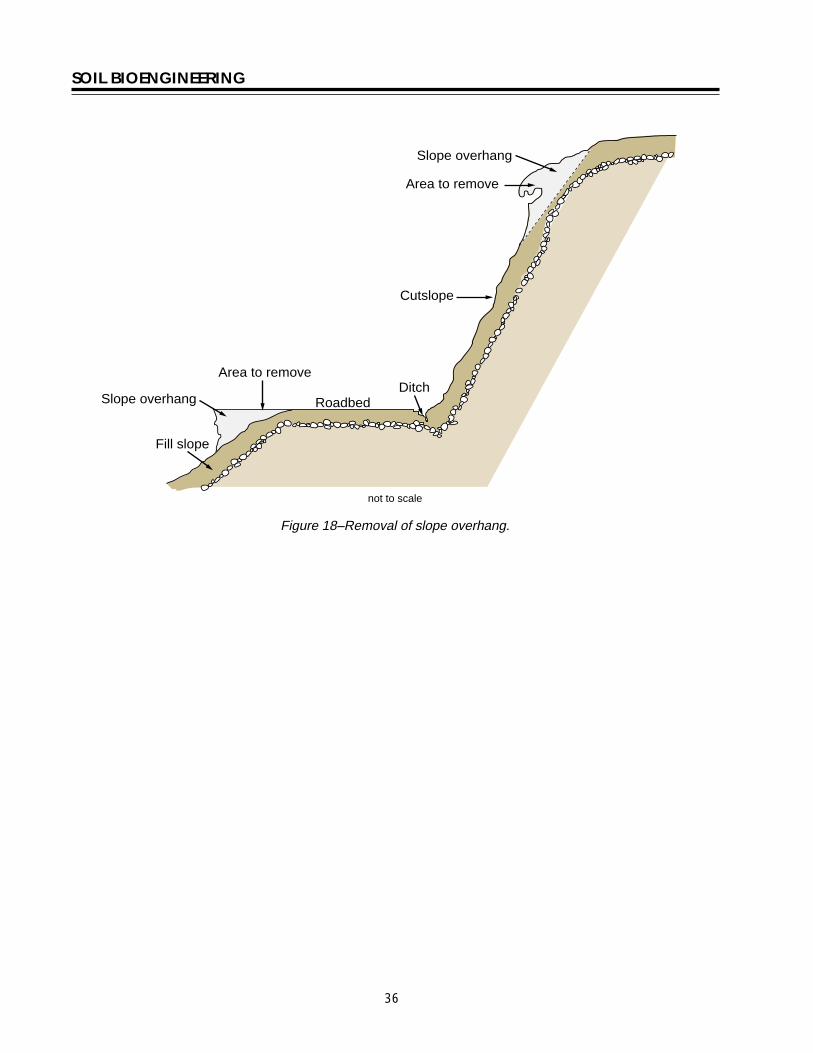
SOIL BIOENGINEERING
Roadbed Ditch
Cutslope
Fill slope
Slope overhang
Slope overhang
Area to remove
Area to remove
not to scale
Figure 18ndashRemoval of slope overhang
36
SOIL BIOENGINEERING
Bender Board Fencing Advantages These structures reduce slope angle providing a stable platform for vegetation to establish Like willow fencing bender board structures trap rolling rocks and sliding debris and protects vegetation growing lower on the slope Bender board fences provide support for small translational or rotational failures
Dry sites where soils receive very little precipitation this type of structure The bender board shelf is considered a temporary planting platform It is important therefore to establish deeper rooting shrubs and trees within the shelves When the structures begins to decay root systems of other plants will serve as the permanent feature
Disadvantage Significant quantity of plant material is required
Redwood or cedar bender board fencing is essentially a fence supported on a short layer of shrub or tree stems Specifically it is a short retaining wall built of redwood or cedar bender fencing with a stem layered base
Tools needed Hand pruners and clippers pulaski or hazel hoe McLeod rake deadblow or rubber hammer wood stakes
Procedure Stem Layered Base bull Begin project at base of treatment area Excavate a
24-inch deep terrace along slope contour and for full width of treatment area The back of the terrace should be dug with an approximate 70 degree angle To allow ample planting platforms space terraces about 5 feet apart
bull Lay 2 feet 6-inch long stems and 2 feet 6-inch long wood stakes (5050 mix) 2-inches apart and for full length of terrace Diameter can range from 12 to 2-inches Approximatly 6-inches will extend beyond slope face
Bender board Fencing bull Drive supporting 4 foot 6-inch (2 by 2) long stakes
2 to 3 feet into ground spaced 1 foot apart and perpendicular to the slope Rebar may be used instead of wooden stakes
bull Weave 10 foot long bender boards through these stakes until the wall reaches a height of 2 feet Once complete the bender board fence wall should be at a 15 degree angle to the slope Note As shown in photo some bender board are too brittle to weave
bull Once the wall frame is constructed carefully rake enough soil into the terrace to cover the stem layered base
37
SOIL BIOENGINEERING
bull Stand in terrace and begin excavation of second bull Move upslope to next terrace alignment and row This process will allow soil into the terrace repeat process to cover the stem layered base
bull A goal should be to construct a 21 slope or less between the top of the bender board fence wall and the bottom of the one above
10 foot long bender boards 14 thick 3-12 wide
2-6 long stakes spaced 3 apart
2 high seven bender boards
2 wide terraces spaced 5 apart
not to scale
4-6 post buried 2-3
Figure 19ndashBender board fencing
38
SOIL BIOENGINEERING
REFERENCES CITED
Bach David H and MacAskill IA 1984 Vegetation and Landscape Engineering Granada London
Bennett Francis W 1975 Methods of Quickly Vegetating Soils of Low Productivity Construction Activities US Environmental Protection Agency Washington DC
Brosius Myra 1985 ldquoThe Restoration of an Urban Stream Using Geomorphic Relationships and Biotechnical Streambank Stabilizationrdquo Athens GA University of Georgia Thesis
Chandler RJ 1991 Slope Stability Engineering Institution of Civil Engineers Thomas Telford Publishing Company
Chatwin S D Howes and D Swantson 1994 A Guide for Management of Landslide Prone Terrain in the Pacific Northwest Second edition Ministry of Forests Crown Publications Victoria BC
Christensen M and J Jacobovitch 1992 Revegetation Projects Everything You Wanted to Know About Live Staking Unpublished report for King County Dept of Public Works Surface Water Management Div Seattle WA
Coppin NJ and IG Richards 1990 Use of Vegetation in Civil Engineering Butterworths London England
Coppin Nick J and R Stiles 1989 The Use of Vegetation in Slope Stabilization Landscape Design with Plants Second Edition ed by Brian Clouston Boca Raton Florida CRC Press 212-234
Edlin HL 1949 Woodland Crafts in Britain BT London Batsford Ltd London
Finney Kevin P 1993 BioEngineering Solutions A Tool for Education Eugene OR University of Oregon Thesis
Finney K 1993 History of Soil Bioengineering Eugene OR Masters Thesis University of Oregon Thesis
Gray DR and AT Leiser 1982 Biotechnical Slope Protection and Erosion Control New YorkVan Nostrand Reinhold Company New York
Gray DH Leiser T Andrew and C A White 1980 Combined Vegetative Structural Slope Stabilization Civil Engineering 50(1)82-85
Gray D R and Sotir RB 1996 Biotechnical and Soil Bioengineering Slope Stabilization John Wiley and Sons Inc
Greenway DR 1987 Vegetation and Slope Stability In Slope Stability John Wiley and Sons Ltd Chapter 6
41
SOIL BIOENGINEERING
Johnson AW and JM Stypula eds 1993 Guidelines for Bank Stabilization Projects In the Rivetine Environments of King County County Department of Public Works Surface Water Management Division Seattle WA
Kraebel CJ 1936 Erosion Control on Mountain Roads USDA Circular No 380 Washington DC USDA
Kraebel CJ 1933 Willow Cuttings for Erosion Control Technical Note No 1 Berkely California USDA California Forest Experiment Station
Larson FE and WE Guse 1981 Propagating Deciduous and Evergreen Shrubs Trees and Vines with Stem Cuttings Pacific Northwest Coop Ext Pub PNW152
Leiser Andrew T J J Nussbaum Kay Burgess Paul Jack and W Thornhill 1974 Revegetation of Disturbed Soils in the Tahoe Basin California Department of Transportation Sacramento California
Lewis EA and LW Ogg 1993 Soil Bioengineering Project Descriptions Unpublished report for Olympic National Forest Hood Canal Hanger District
Leys Emil 1978 Wilhelm Hassenteufel 80 Years Old Garten und Landschaft in China Vol 4 Part 3 Cambridge The University Press
Maleike R and RL Hummel 1988 Planting Landscape Plants Wash State Univ Coop Ext Pub EB1505
Polster Environmental Services 1998 Soil Bioengineering for Forest Land Reclamation and Stabilization British Columbia Ministry of Forests
Robbin B Sotir amp Associates A Brief History of Soil Bioengineering Unpublished and undated manuscript
Schiechtl Hugo 1980 Bioengineering For Land Reclamation and Conservation Edmonton Canada The University of Alberta Press
Schiechtl H M and R Stern 1997 Ground Bioengineering Techniques for Slope Protection and Erosion Control Blackwell Science Publications ISBN 0-632-04061-0
Sotir RB and DH Gray 1992 Soil Bioengineering for Upland Slope Protection and Erosion Reduction Engineering Field Handbook Soil Conservation Service Chapter 18
Stiles Richard (172) 57-61 1988 Engineering with Vegetation Landscape Design (172) 57-61
Stiles Richard1991 Re-inventing the Wheel Landscape Design (203)
42
SOIL BIOENGINEERING
Weaver WE and MA Madej 1981 Erosion Control Techniques Used in Redwood National Park In Davies TRH and AJ Pearce eds Erosion and Sediment Transport in Pacific Rim Steeplands Washington DC Intrsquol Assoc Hydrological Sciences 640-654 IAHS-AISH Pub 132
Westmacott Richard 1985 The Rediscovered Arts of Twilling and Wattling Landscape Architecture 75(4)95-98
White Charles A and AL Frank S 1978 Demonstration of Erosion and Sediment Control Technology Lake Tahoe Region of California EPA-6002-78-208 Municipal Environmental Research Laboratory Office of Research and Development US Environmental Protection Agency Cincinnati Ohio
Ziemer RR 1981 Roots and the Stability of Forested Slopes In Davies TRH and AJ Pearce eds Erosion and Sediment Transport in Pacific Rim Steeplands
43
SOIL BIOENGINEERING
About the Authorhellip
Lisa Lewis graduated in 1987 from Fort Valley State University Fort Valley Georgia with a Bachelor of Science degree in Soil and Plant Sciences Lisa began her career with the Forest Service in August 1987 on the Hood Canal Ranger District She continued her career in the Pacific Northwest and since 1998 she has been a soil scientist with the National Riparian Service Team (NRST) As a member of the NRST Lisa provides training and technology transfer consulting and advisory services and program review for riparian restoration nationwide She specializes in road management issues and soil bioengineering techniques
Library Card
Lewis Lisa 2000 Soil bioengineeringmdashan alternative to roadside managementmdasha practical guide Technical Report 0077-1801-SDTDC San Dimas CA US Department of Agriculture Forest Service San Dimas Technology and Development Center 44 p
This publication provides field personnel with the basic merits of soil bioengineering concepts and gives examples of several techniques especially effective in stabilizing and revegetating upland roadside environments The information provided in this document is intended to stimulate additional interest for the reader to seek out and use these and other soil bioengineering applications
Soil bioengineering is the use of live plant materials and flexible engineering techniques to alleviate environmental problems such as destabilized and eroding slopes Unlike other technologies in which plants are chiefly an aesthetic component of the project in soil bioengineering systems plants are an important structural component
Keywords Soil bioengineering road management road maintenance restoration erosion native plant materials revegetation
Additional single copies of this document may be ordered from
USDA Forest Service San Dimas Technology and Development Center
ATTN Richard Martinez 444 E Bonita Avenue San Dimas CA 91773
Phone (909) 599-1267 x201 Fax (909) 592-2309
E-Mail rmartinezwo_sdtdcfsfedus FSNotes Richard MartinezWOUSDAFS
For additional technical information contact Lisa Lewis at the following address
USDA Forest Service National Riparian Service Team
3050 NE 3rd Street PO Box 550
Prineville OR 98854 Phone (541) 416-6788
E-Mail l3Lewisorblmgov
An electronic copy of this document is available on the Forest Servicersquos FSWeb
Intranet at httpfswebsdtdcwofsfedus
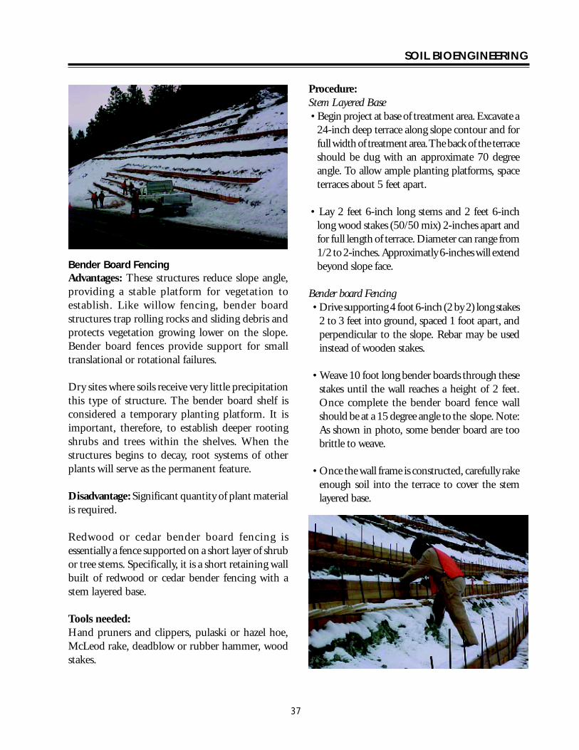
SOIL BIOENGINEERING
Bender Board Fencing Advantages These structures reduce slope angle providing a stable platform for vegetation to establish Like willow fencing bender board structures trap rolling rocks and sliding debris and protects vegetation growing lower on the slope Bender board fences provide support for small translational or rotational failures
Dry sites where soils receive very little precipitation this type of structure The bender board shelf is considered a temporary planting platform It is important therefore to establish deeper rooting shrubs and trees within the shelves When the structures begins to decay root systems of other plants will serve as the permanent feature
Disadvantage Significant quantity of plant material is required
Redwood or cedar bender board fencing is essentially a fence supported on a short layer of shrub or tree stems Specifically it is a short retaining wall built of redwood or cedar bender fencing with a stem layered base
Tools needed Hand pruners and clippers pulaski or hazel hoe McLeod rake deadblow or rubber hammer wood stakes
Procedure Stem Layered Base bull Begin project at base of treatment area Excavate a
24-inch deep terrace along slope contour and for full width of treatment area The back of the terrace should be dug with an approximate 70 degree angle To allow ample planting platforms space terraces about 5 feet apart
bull Lay 2 feet 6-inch long stems and 2 feet 6-inch long wood stakes (5050 mix) 2-inches apart and for full length of terrace Diameter can range from 12 to 2-inches Approximatly 6-inches will extend beyond slope face
Bender board Fencing bull Drive supporting 4 foot 6-inch (2 by 2) long stakes
2 to 3 feet into ground spaced 1 foot apart and perpendicular to the slope Rebar may be used instead of wooden stakes
bull Weave 10 foot long bender boards through these stakes until the wall reaches a height of 2 feet Once complete the bender board fence wall should be at a 15 degree angle to the slope Note As shown in photo some bender board are too brittle to weave
bull Once the wall frame is constructed carefully rake enough soil into the terrace to cover the stem layered base
37
SOIL BIOENGINEERING
bull Stand in terrace and begin excavation of second bull Move upslope to next terrace alignment and row This process will allow soil into the terrace repeat process to cover the stem layered base
bull A goal should be to construct a 21 slope or less between the top of the bender board fence wall and the bottom of the one above
10 foot long bender boards 14 thick 3-12 wide
2-6 long stakes spaced 3 apart
2 high seven bender boards
2 wide terraces spaced 5 apart
not to scale
4-6 post buried 2-3
Figure 19ndashBender board fencing
38
SOIL BIOENGINEERING
REFERENCES CITED
Bach David H and MacAskill IA 1984 Vegetation and Landscape Engineering Granada London
Bennett Francis W 1975 Methods of Quickly Vegetating Soils of Low Productivity Construction Activities US Environmental Protection Agency Washington DC
Brosius Myra 1985 ldquoThe Restoration of an Urban Stream Using Geomorphic Relationships and Biotechnical Streambank Stabilizationrdquo Athens GA University of Georgia Thesis
Chandler RJ 1991 Slope Stability Engineering Institution of Civil Engineers Thomas Telford Publishing Company
Chatwin S D Howes and D Swantson 1994 A Guide for Management of Landslide Prone Terrain in the Pacific Northwest Second edition Ministry of Forests Crown Publications Victoria BC
Christensen M and J Jacobovitch 1992 Revegetation Projects Everything You Wanted to Know About Live Staking Unpublished report for King County Dept of Public Works Surface Water Management Div Seattle WA
Coppin NJ and IG Richards 1990 Use of Vegetation in Civil Engineering Butterworths London England
Coppin Nick J and R Stiles 1989 The Use of Vegetation in Slope Stabilization Landscape Design with Plants Second Edition ed by Brian Clouston Boca Raton Florida CRC Press 212-234
Edlin HL 1949 Woodland Crafts in Britain BT London Batsford Ltd London
Finney Kevin P 1993 BioEngineering Solutions A Tool for Education Eugene OR University of Oregon Thesis
Finney K 1993 History of Soil Bioengineering Eugene OR Masters Thesis University of Oregon Thesis
Gray DR and AT Leiser 1982 Biotechnical Slope Protection and Erosion Control New YorkVan Nostrand Reinhold Company New York
Gray DH Leiser T Andrew and C A White 1980 Combined Vegetative Structural Slope Stabilization Civil Engineering 50(1)82-85
Gray D R and Sotir RB 1996 Biotechnical and Soil Bioengineering Slope Stabilization John Wiley and Sons Inc
Greenway DR 1987 Vegetation and Slope Stability In Slope Stability John Wiley and Sons Ltd Chapter 6
41
SOIL BIOENGINEERING
Johnson AW and JM Stypula eds 1993 Guidelines for Bank Stabilization Projects In the Rivetine Environments of King County County Department of Public Works Surface Water Management Division Seattle WA
Kraebel CJ 1936 Erosion Control on Mountain Roads USDA Circular No 380 Washington DC USDA
Kraebel CJ 1933 Willow Cuttings for Erosion Control Technical Note No 1 Berkely California USDA California Forest Experiment Station
Larson FE and WE Guse 1981 Propagating Deciduous and Evergreen Shrubs Trees and Vines with Stem Cuttings Pacific Northwest Coop Ext Pub PNW152
Leiser Andrew T J J Nussbaum Kay Burgess Paul Jack and W Thornhill 1974 Revegetation of Disturbed Soils in the Tahoe Basin California Department of Transportation Sacramento California
Lewis EA and LW Ogg 1993 Soil Bioengineering Project Descriptions Unpublished report for Olympic National Forest Hood Canal Hanger District
Leys Emil 1978 Wilhelm Hassenteufel 80 Years Old Garten und Landschaft in China Vol 4 Part 3 Cambridge The University Press
Maleike R and RL Hummel 1988 Planting Landscape Plants Wash State Univ Coop Ext Pub EB1505
Polster Environmental Services 1998 Soil Bioengineering for Forest Land Reclamation and Stabilization British Columbia Ministry of Forests
Robbin B Sotir amp Associates A Brief History of Soil Bioengineering Unpublished and undated manuscript
Schiechtl Hugo 1980 Bioengineering For Land Reclamation and Conservation Edmonton Canada The University of Alberta Press
Schiechtl H M and R Stern 1997 Ground Bioengineering Techniques for Slope Protection and Erosion Control Blackwell Science Publications ISBN 0-632-04061-0
Sotir RB and DH Gray 1992 Soil Bioengineering for Upland Slope Protection and Erosion Reduction Engineering Field Handbook Soil Conservation Service Chapter 18
Stiles Richard (172) 57-61 1988 Engineering with Vegetation Landscape Design (172) 57-61
Stiles Richard1991 Re-inventing the Wheel Landscape Design (203)
42
SOIL BIOENGINEERING
Weaver WE and MA Madej 1981 Erosion Control Techniques Used in Redwood National Park In Davies TRH and AJ Pearce eds Erosion and Sediment Transport in Pacific Rim Steeplands Washington DC Intrsquol Assoc Hydrological Sciences 640-654 IAHS-AISH Pub 132
Westmacott Richard 1985 The Rediscovered Arts of Twilling and Wattling Landscape Architecture 75(4)95-98
White Charles A and AL Frank S 1978 Demonstration of Erosion and Sediment Control Technology Lake Tahoe Region of California EPA-6002-78-208 Municipal Environmental Research Laboratory Office of Research and Development US Environmental Protection Agency Cincinnati Ohio
Ziemer RR 1981 Roots and the Stability of Forested Slopes In Davies TRH and AJ Pearce eds Erosion and Sediment Transport in Pacific Rim Steeplands
43
SOIL BIOENGINEERING
About the Authorhellip
Lisa Lewis graduated in 1987 from Fort Valley State University Fort Valley Georgia with a Bachelor of Science degree in Soil and Plant Sciences Lisa began her career with the Forest Service in August 1987 on the Hood Canal Ranger District She continued her career in the Pacific Northwest and since 1998 she has been a soil scientist with the National Riparian Service Team (NRST) As a member of the NRST Lisa provides training and technology transfer consulting and advisory services and program review for riparian restoration nationwide She specializes in road management issues and soil bioengineering techniques
Library Card
Lewis Lisa 2000 Soil bioengineeringmdashan alternative to roadside managementmdasha practical guide Technical Report 0077-1801-SDTDC San Dimas CA US Department of Agriculture Forest Service San Dimas Technology and Development Center 44 p
This publication provides field personnel with the basic merits of soil bioengineering concepts and gives examples of several techniques especially effective in stabilizing and revegetating upland roadside environments The information provided in this document is intended to stimulate additional interest for the reader to seek out and use these and other soil bioengineering applications
Soil bioengineering is the use of live plant materials and flexible engineering techniques to alleviate environmental problems such as destabilized and eroding slopes Unlike other technologies in which plants are chiefly an aesthetic component of the project in soil bioengineering systems plants are an important structural component
Keywords Soil bioengineering road management road maintenance restoration erosion native plant materials revegetation
Additional single copies of this document may be ordered from
USDA Forest Service San Dimas Technology and Development Center
ATTN Richard Martinez 444 E Bonita Avenue San Dimas CA 91773
Phone (909) 599-1267 x201 Fax (909) 592-2309
E-Mail rmartinezwo_sdtdcfsfedus FSNotes Richard MartinezWOUSDAFS
For additional technical information contact Lisa Lewis at the following address
USDA Forest Service National Riparian Service Team
3050 NE 3rd Street PO Box 550
Prineville OR 98854 Phone (541) 416-6788
E-Mail l3Lewisorblmgov
An electronic copy of this document is available on the Forest Servicersquos FSWeb
Intranet at httpfswebsdtdcwofsfedus
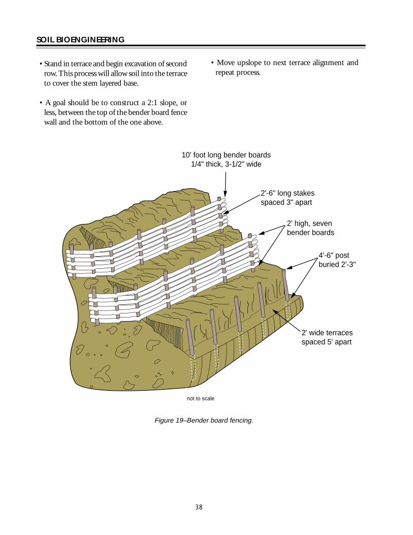
SOIL BIOENGINEERING
bull Stand in terrace and begin excavation of second bull Move upslope to next terrace alignment and row This process will allow soil into the terrace repeat process to cover the stem layered base
bull A goal should be to construct a 21 slope or less between the top of the bender board fence wall and the bottom of the one above
10 foot long bender boards 14 thick 3-12 wide
2-6 long stakes spaced 3 apart
2 high seven bender boards
2 wide terraces spaced 5 apart
not to scale
4-6 post buried 2-3
Figure 19ndashBender board fencing
38
SOIL BIOENGINEERING
REFERENCES CITED
Bach David H and MacAskill IA 1984 Vegetation and Landscape Engineering Granada London
Bennett Francis W 1975 Methods of Quickly Vegetating Soils of Low Productivity Construction Activities US Environmental Protection Agency Washington DC
Brosius Myra 1985 ldquoThe Restoration of an Urban Stream Using Geomorphic Relationships and Biotechnical Streambank Stabilizationrdquo Athens GA University of Georgia Thesis
Chandler RJ 1991 Slope Stability Engineering Institution of Civil Engineers Thomas Telford Publishing Company
Chatwin S D Howes and D Swantson 1994 A Guide for Management of Landslide Prone Terrain in the Pacific Northwest Second edition Ministry of Forests Crown Publications Victoria BC
Christensen M and J Jacobovitch 1992 Revegetation Projects Everything You Wanted to Know About Live Staking Unpublished report for King County Dept of Public Works Surface Water Management Div Seattle WA
Coppin NJ and IG Richards 1990 Use of Vegetation in Civil Engineering Butterworths London England
Coppin Nick J and R Stiles 1989 The Use of Vegetation in Slope Stabilization Landscape Design with Plants Second Edition ed by Brian Clouston Boca Raton Florida CRC Press 212-234
Edlin HL 1949 Woodland Crafts in Britain BT London Batsford Ltd London
Finney Kevin P 1993 BioEngineering Solutions A Tool for Education Eugene OR University of Oregon Thesis
Finney K 1993 History of Soil Bioengineering Eugene OR Masters Thesis University of Oregon Thesis
Gray DR and AT Leiser 1982 Biotechnical Slope Protection and Erosion Control New YorkVan Nostrand Reinhold Company New York
Gray DH Leiser T Andrew and C A White 1980 Combined Vegetative Structural Slope Stabilization Civil Engineering 50(1)82-85
Gray D R and Sotir RB 1996 Biotechnical and Soil Bioengineering Slope Stabilization John Wiley and Sons Inc
Greenway DR 1987 Vegetation and Slope Stability In Slope Stability John Wiley and Sons Ltd Chapter 6
41
SOIL BIOENGINEERING
Johnson AW and JM Stypula eds 1993 Guidelines for Bank Stabilization Projects In the Rivetine Environments of King County County Department of Public Works Surface Water Management Division Seattle WA
Kraebel CJ 1936 Erosion Control on Mountain Roads USDA Circular No 380 Washington DC USDA
Kraebel CJ 1933 Willow Cuttings for Erosion Control Technical Note No 1 Berkely California USDA California Forest Experiment Station
Larson FE and WE Guse 1981 Propagating Deciduous and Evergreen Shrubs Trees and Vines with Stem Cuttings Pacific Northwest Coop Ext Pub PNW152
Leiser Andrew T J J Nussbaum Kay Burgess Paul Jack and W Thornhill 1974 Revegetation of Disturbed Soils in the Tahoe Basin California Department of Transportation Sacramento California
Lewis EA and LW Ogg 1993 Soil Bioengineering Project Descriptions Unpublished report for Olympic National Forest Hood Canal Hanger District
Leys Emil 1978 Wilhelm Hassenteufel 80 Years Old Garten und Landschaft in China Vol 4 Part 3 Cambridge The University Press
Maleike R and RL Hummel 1988 Planting Landscape Plants Wash State Univ Coop Ext Pub EB1505
Polster Environmental Services 1998 Soil Bioengineering for Forest Land Reclamation and Stabilization British Columbia Ministry of Forests
Robbin B Sotir amp Associates A Brief History of Soil Bioengineering Unpublished and undated manuscript
Schiechtl Hugo 1980 Bioengineering For Land Reclamation and Conservation Edmonton Canada The University of Alberta Press
Schiechtl H M and R Stern 1997 Ground Bioengineering Techniques for Slope Protection and Erosion Control Blackwell Science Publications ISBN 0-632-04061-0
Sotir RB and DH Gray 1992 Soil Bioengineering for Upland Slope Protection and Erosion Reduction Engineering Field Handbook Soil Conservation Service Chapter 18
Stiles Richard (172) 57-61 1988 Engineering with Vegetation Landscape Design (172) 57-61
Stiles Richard1991 Re-inventing the Wheel Landscape Design (203)
42
SOIL BIOENGINEERING
Weaver WE and MA Madej 1981 Erosion Control Techniques Used in Redwood National Park In Davies TRH and AJ Pearce eds Erosion and Sediment Transport in Pacific Rim Steeplands Washington DC Intrsquol Assoc Hydrological Sciences 640-654 IAHS-AISH Pub 132
Westmacott Richard 1985 The Rediscovered Arts of Twilling and Wattling Landscape Architecture 75(4)95-98
White Charles A and AL Frank S 1978 Demonstration of Erosion and Sediment Control Technology Lake Tahoe Region of California EPA-6002-78-208 Municipal Environmental Research Laboratory Office of Research and Development US Environmental Protection Agency Cincinnati Ohio
Ziemer RR 1981 Roots and the Stability of Forested Slopes In Davies TRH and AJ Pearce eds Erosion and Sediment Transport in Pacific Rim Steeplands
43
SOIL BIOENGINEERING
About the Authorhellip
Lisa Lewis graduated in 1987 from Fort Valley State University Fort Valley Georgia with a Bachelor of Science degree in Soil and Plant Sciences Lisa began her career with the Forest Service in August 1987 on the Hood Canal Ranger District She continued her career in the Pacific Northwest and since 1998 she has been a soil scientist with the National Riparian Service Team (NRST) As a member of the NRST Lisa provides training and technology transfer consulting and advisory services and program review for riparian restoration nationwide She specializes in road management issues and soil bioengineering techniques
Library Card
Lewis Lisa 2000 Soil bioengineeringmdashan alternative to roadside managementmdasha practical guide Technical Report 0077-1801-SDTDC San Dimas CA US Department of Agriculture Forest Service San Dimas Technology and Development Center 44 p
This publication provides field personnel with the basic merits of soil bioengineering concepts and gives examples of several techniques especially effective in stabilizing and revegetating upland roadside environments The information provided in this document is intended to stimulate additional interest for the reader to seek out and use these and other soil bioengineering applications
Soil bioengineering is the use of live plant materials and flexible engineering techniques to alleviate environmental problems such as destabilized and eroding slopes Unlike other technologies in which plants are chiefly an aesthetic component of the project in soil bioengineering systems plants are an important structural component
Keywords Soil bioengineering road management road maintenance restoration erosion native plant materials revegetation
Additional single copies of this document may be ordered from
USDA Forest Service San Dimas Technology and Development Center
ATTN Richard Martinez 444 E Bonita Avenue San Dimas CA 91773
Phone (909) 599-1267 x201 Fax (909) 592-2309
E-Mail rmartinezwo_sdtdcfsfedus FSNotes Richard MartinezWOUSDAFS
For additional technical information contact Lisa Lewis at the following address
USDA Forest Service National Riparian Service Team
3050 NE 3rd Street PO Box 550
Prineville OR 98854 Phone (541) 416-6788
E-Mail l3Lewisorblmgov
An electronic copy of this document is available on the Forest Servicersquos FSWeb
Intranet at httpfswebsdtdcwofsfedus
SOIL BIOENGINEERING
REFERENCES CITED
Bach David H and MacAskill IA 1984 Vegetation and Landscape Engineering Granada London
Bennett Francis W 1975 Methods of Quickly Vegetating Soils of Low Productivity Construction Activities US Environmental Protection Agency Washington DC
Brosius Myra 1985 ldquoThe Restoration of an Urban Stream Using Geomorphic Relationships and Biotechnical Streambank Stabilizationrdquo Athens GA University of Georgia Thesis
Chandler RJ 1991 Slope Stability Engineering Institution of Civil Engineers Thomas Telford Publishing Company
Chatwin S D Howes and D Swantson 1994 A Guide for Management of Landslide Prone Terrain in the Pacific Northwest Second edition Ministry of Forests Crown Publications Victoria BC
Christensen M and J Jacobovitch 1992 Revegetation Projects Everything You Wanted to Know About Live Staking Unpublished report for King County Dept of Public Works Surface Water Management Div Seattle WA
Coppin NJ and IG Richards 1990 Use of Vegetation in Civil Engineering Butterworths London England
Coppin Nick J and R Stiles 1989 The Use of Vegetation in Slope Stabilization Landscape Design with Plants Second Edition ed by Brian Clouston Boca Raton Florida CRC Press 212-234
Edlin HL 1949 Woodland Crafts in Britain BT London Batsford Ltd London
Finney Kevin P 1993 BioEngineering Solutions A Tool for Education Eugene OR University of Oregon Thesis
Finney K 1993 History of Soil Bioengineering Eugene OR Masters Thesis University of Oregon Thesis
Gray DR and AT Leiser 1982 Biotechnical Slope Protection and Erosion Control New YorkVan Nostrand Reinhold Company New York
Gray DH Leiser T Andrew and C A White 1980 Combined Vegetative Structural Slope Stabilization Civil Engineering 50(1)82-85
Gray D R and Sotir RB 1996 Biotechnical and Soil Bioengineering Slope Stabilization John Wiley and Sons Inc
Greenway DR 1987 Vegetation and Slope Stability In Slope Stability John Wiley and Sons Ltd Chapter 6
41
SOIL BIOENGINEERING
Johnson AW and JM Stypula eds 1993 Guidelines for Bank Stabilization Projects In the Rivetine Environments of King County County Department of Public Works Surface Water Management Division Seattle WA
Kraebel CJ 1936 Erosion Control on Mountain Roads USDA Circular No 380 Washington DC USDA
Kraebel CJ 1933 Willow Cuttings for Erosion Control Technical Note No 1 Berkely California USDA California Forest Experiment Station
Larson FE and WE Guse 1981 Propagating Deciduous and Evergreen Shrubs Trees and Vines with Stem Cuttings Pacific Northwest Coop Ext Pub PNW152
Leiser Andrew T J J Nussbaum Kay Burgess Paul Jack and W Thornhill 1974 Revegetation of Disturbed Soils in the Tahoe Basin California Department of Transportation Sacramento California
Lewis EA and LW Ogg 1993 Soil Bioengineering Project Descriptions Unpublished report for Olympic National Forest Hood Canal Hanger District
Leys Emil 1978 Wilhelm Hassenteufel 80 Years Old Garten und Landschaft in China Vol 4 Part 3 Cambridge The University Press
Maleike R and RL Hummel 1988 Planting Landscape Plants Wash State Univ Coop Ext Pub EB1505
Polster Environmental Services 1998 Soil Bioengineering for Forest Land Reclamation and Stabilization British Columbia Ministry of Forests
Robbin B Sotir amp Associates A Brief History of Soil Bioengineering Unpublished and undated manuscript
Schiechtl Hugo 1980 Bioengineering For Land Reclamation and Conservation Edmonton Canada The University of Alberta Press
Schiechtl H M and R Stern 1997 Ground Bioengineering Techniques for Slope Protection and Erosion Control Blackwell Science Publications ISBN 0-632-04061-0
Sotir RB and DH Gray 1992 Soil Bioengineering for Upland Slope Protection and Erosion Reduction Engineering Field Handbook Soil Conservation Service Chapter 18
Stiles Richard (172) 57-61 1988 Engineering with Vegetation Landscape Design (172) 57-61
Stiles Richard1991 Re-inventing the Wheel Landscape Design (203)
42
SOIL BIOENGINEERING
Weaver WE and MA Madej 1981 Erosion Control Techniques Used in Redwood National Park In Davies TRH and AJ Pearce eds Erosion and Sediment Transport in Pacific Rim Steeplands Washington DC Intrsquol Assoc Hydrological Sciences 640-654 IAHS-AISH Pub 132
Westmacott Richard 1985 The Rediscovered Arts of Twilling and Wattling Landscape Architecture 75(4)95-98
White Charles A and AL Frank S 1978 Demonstration of Erosion and Sediment Control Technology Lake Tahoe Region of California EPA-6002-78-208 Municipal Environmental Research Laboratory Office of Research and Development US Environmental Protection Agency Cincinnati Ohio
Ziemer RR 1981 Roots and the Stability of Forested Slopes In Davies TRH and AJ Pearce eds Erosion and Sediment Transport in Pacific Rim Steeplands
43
SOIL BIOENGINEERING
About the Authorhellip
Lisa Lewis graduated in 1987 from Fort Valley State University Fort Valley Georgia with a Bachelor of Science degree in Soil and Plant Sciences Lisa began her career with the Forest Service in August 1987 on the Hood Canal Ranger District She continued her career in the Pacific Northwest and since 1998 she has been a soil scientist with the National Riparian Service Team (NRST) As a member of the NRST Lisa provides training and technology transfer consulting and advisory services and program review for riparian restoration nationwide She specializes in road management issues and soil bioengineering techniques
Library Card
Lewis Lisa 2000 Soil bioengineeringmdashan alternative to roadside managementmdasha practical guide Technical Report 0077-1801-SDTDC San Dimas CA US Department of Agriculture Forest Service San Dimas Technology and Development Center 44 p
This publication provides field personnel with the basic merits of soil bioengineering concepts and gives examples of several techniques especially effective in stabilizing and revegetating upland roadside environments The information provided in this document is intended to stimulate additional interest for the reader to seek out and use these and other soil bioengineering applications
Soil bioengineering is the use of live plant materials and flexible engineering techniques to alleviate environmental problems such as destabilized and eroding slopes Unlike other technologies in which plants are chiefly an aesthetic component of the project in soil bioengineering systems plants are an important structural component
Keywords Soil bioengineering road management road maintenance restoration erosion native plant materials revegetation
Additional single copies of this document may be ordered from
USDA Forest Service San Dimas Technology and Development Center
ATTN Richard Martinez 444 E Bonita Avenue San Dimas CA 91773
Phone (909) 599-1267 x201 Fax (909) 592-2309
E-Mail rmartinezwo_sdtdcfsfedus FSNotes Richard MartinezWOUSDAFS
For additional technical information contact Lisa Lewis at the following address
USDA Forest Service National Riparian Service Team
3050 NE 3rd Street PO Box 550
Prineville OR 98854 Phone (541) 416-6788
E-Mail l3Lewisorblmgov
An electronic copy of this document is available on the Forest Servicersquos FSWeb
Intranet at httpfswebsdtdcwofsfedus

SOIL BIOENGINEERING
About the Authorhellip
Lisa Lewis graduated in 1987 from Fort Valley State University Fort Valley Georgia with a Bachelor of Science degree in Soil and Plant Sciences Lisa began her career with the Forest Service in August 1987 on the Hood Canal Ranger District She continued her career in the Pacific Northwest and since 1998 she has been a soil scientist with the National Riparian Service Team (NRST) As a member of the NRST Lisa provides training and technology transfer consulting and advisory services and program review for riparian restoration nationwide She specializes in road management issues and soil bioengineering techniques
Library Card
Lewis Lisa 2000 Soil bioengineeringmdashan alternative to roadside managementmdasha practical guide Technical Report 0077-1801-SDTDC San Dimas CA US Department of Agriculture Forest Service San Dimas Technology and Development Center 44 p
This publication provides field personnel with the basic merits of soil bioengineering concepts and gives examples of several techniques especially effective in stabilizing and revegetating upland roadside environments The information provided in this document is intended to stimulate additional interest for the reader to seek out and use these and other soil bioengineering applications
Soil bioengineering is the use of live plant materials and flexible engineering techniques to alleviate environmental problems such as destabilized and eroding slopes Unlike other technologies in which plants are chiefly an aesthetic component of the project in soil bioengineering systems plants are an important structural component
Keywords Soil bioengineering road management road maintenance restoration erosion native plant materials revegetation
Additional single copies of this document may be ordered from
USDA Forest Service San Dimas Technology and Development Center
ATTN Richard Martinez 444 E Bonita Avenue San Dimas CA 91773
Phone (909) 599-1267 x201 Fax (909) 592-2309
E-Mail rmartinezwo_sdtdcfsfedus FSNotes Richard MartinezWOUSDAFS
For additional technical information contact Lisa Lewis at the following address
USDA Forest Service National Riparian Service Team
3050 NE 3rd Street PO Box 550
Prineville OR 98854 Phone (541) 416-6788
E-Mail l3Lewisorblmgov
An electronic copy of this document is available on the Forest Servicersquos FSWeb
Intranet at httpfswebsdtdcwofsfedus