Embed Size (px)
Citation preview

XIII. STRESSES IN SOILS Soil Mechanics
Mohr’s Circle of Stresses

MOHR’S CIRCLE OF STRESSES Introduction
Soils are essentially frictional materials. They are comprised of individual particles
that can slide and roll relative to one another. In the discipline of soil mechanics
it is generally assumed that the particles are not cemented.
One consequence of the frictional nature is that the strength depends on the
effective stresses in the soil. As the effective stresses increase with depth, so in
general will the strength.
The strength will also depend on whether the soil deformation occurs under fully
drained conditions, constant volume (undrained) conditions, or with some
intermediate state of drainage. In each case different excess pore pressures will
occur resulting in different effective stresses, and hence different strengths. In
assessing the stability of soil constructions analyses are usually performed to
check the short term (undrained) and long term (fully drained) conditions.

MOHR’S CIRCLE OF STRESSES Concept of Mohr’s Circle
In the late 1800s, Mohr (1887) presented a graphic solution to determine stresses
at a mass. When an external load is applied, an infinitesimal element will be
subjected to the boundary stresses as seen in Figure 10.1.
MOHR’S CIRCLE OF STRESSES Concept of Mohr’s Circle
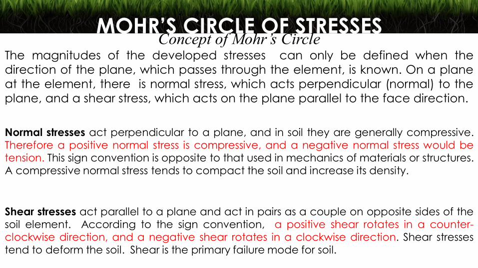
The magnitudes of the developed stresses can only be defined when the
direction of the plane, which passes through the element, is known. On a plane
at the element, there is normal stress, which acts perpendicular (normal) to the
plane, and a shear stress, which acts on the plane parallel to the face direction.
Normal stresses act perpendicular to a plane, and in soil they are generally compressive. Therefore a positive normal stress is compressive, and a negative normal stress would be tension. This sign convention is opposite to that used in mechanics of materials or structures. A compressive normal stress tends to compact the soil and increase its density.
Shear stresses act parallel to a plane and act in pairs as a couple on opposite sides of the soil element. According to the sign convention, a positive shear rotates in a counter-clockwise direction, and a negative shear rotates in a clockwise direction. Shear stresses tend to deform the soil. Shear is the primary failure mode for soil.

MOHR’S CIRCLE OF STRESSES Concept of Mohr’s Circle
In Figure 10.1, normal stress 𝜎𝜃 and shear stress 𝜏𝜃 are shown on the 𝜃-plane,
which inclines at +𝜃 (counterclockwise) angle from the horizontal plane. The
magnitude of 𝜎𝜃 and 𝜏𝜃 do change when the 𝜃 angle changes. Mohr’s circle is a
technique to graphically determine the values of 𝜎𝜃 and 𝜏𝜃 on a given plane
with inclination 𝜃 angle. Note that Mohr’s stress solution is applied only to the
two-dimensional (plane strain) problems.

MOHR’S CIRCLE OF STRESSES Stress Transformation
Figure 10.2a shows an infinitesimal element, which is subjected to boundary normal stress 𝜎𝑥 and shear stress 𝜏𝑥𝑦 on x-plane and 𝜎𝑦 and 𝜏𝑦𝑥 on y-plane. These
stresses maintain a static equilibrium; 𝜏𝑥𝑦 is the shear stress applied on x-plane in
y-direction and 𝜏𝑦𝑥 is the one on y-plane in x-direction. We call 𝜏𝑥𝑦 and 𝜏𝑦𝑥
conjugated shear stresses |𝜏𝑥𝑦| = |𝜏𝑥𝑦|, maintaining the moment equilibrium of
the element.

MOHR’S CIRCLE OF STRESSES Stress Transformation
Figure 10.2b shows a triangular element ABE with all the boundary stresses on it.
Assign AE distance as unity. All normal and shear stresses are assumed to have
positive values in the assigned directions in the figure. Applying horizontal and
vertical force equilibriums to stresses on the element ABE:
And by knowing that 𝜏𝑥𝑦 = 𝜏𝑦𝑥, 𝜎𝜃 and 𝜏𝜃 are solved as

MOHR’S CIRCLE OF STRESSES Stress Transformation
By changing 𝜃 values, a combination of 𝜎𝜃 and 𝜏𝜃 values on any arbitrary 𝜃
plane can be obtained from Equation 10.3 and Equation 10.4.
And tan 2𝜃 takes a certain value for given 𝜏𝑥𝑦, 𝜎𝑦, and 𝜎𝑥. This implies that the
maximum or the minimum normal stress, and the zero shear stress appear on the
same 𝜃 (𝜃 plane); the condition repeats in every 90 degrees from the nature of
tan 2𝜃 .
When 𝑑𝜎𝜃
𝑑𝜃= 0 is applied to Equation 10.3 to find the 𝜃 values for the maximum or
the minimum normal stress, or 𝜏𝜃 = 0 is applied to Equation 10.4 to seek the 𝜃
value for zero shear stress, the following equation emerges:

MOHR’S CIRCLE OF STRESSES Stress Transformation
This condition is assigned as the principal stress condition. The maximum normal
stress with the zero shear stress is called the major principal stress 𝝈𝟏, while the
minimum normal stress with the zero shear stress is called the minor principal stress 𝝈𝟑 (note that 𝜎3 < 𝜎1). These principal stresses act on the major and the
minor principal stress planes and intersect each other with 90 degrees as seen in
Figure 10.3.

MOHR’S CIRCLE OF STRESSES Stress Transformation
By substituting Equation 10.5 into Equation 10.3 and Equation 10.4, Equation 10.6
and Equation 10.7 are obtained.

MOHR’S CIRCLE OF STRESSES Stress Transformation
In Equation 10.6, the larger value is assigned as 𝜎1 and the smaller one as 𝜎3, and
the following major and minor principal stresses are obtained:
In Figure 10.2, when y-plane coincides with the major principal stress plane and x-plane is the minor principal stress plane, 𝜎𝑦 = 𝜎1, 𝜎𝑥 = 𝜎3, and 𝜏𝑥𝑦 = 𝜏𝑦𝑥 = 0;
Equations 10.3 and 10.4 yields to Equations 10.10 and 10.11.

MOHR’S CIRCLE OF STRESSES Constructing Mohr’s Circle and Using It
Mohr's circle is a graphical method to determine shear and normal stresses on
planes at various angles. It may also be used to determine principal stresses and
principal planes. Mohr's circle is constructed on a graph where the x-axis
represents normal stress and the y-axis represents shear stress. The sign
convention in geotechnical engineering is:

MOHR’S CIRCLE OF STRESSES Constructing Mohr’s Circle and Using It
MOHR’S CIRCLE OF STRESSES Constructing Mohr’s Circle and Using It
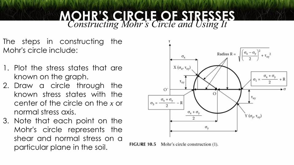
The steps in constructing the
Mohr's circle include:
1. Plot the stress states that are
known on the graph.
2. Draw a circle through the
known stress states with the
center of the circle on the x or
normal stress axis.
3. Note that each point on the
Mohr's circle represents the
shear and normal stress on a
particular plane in the soil.

MOHR’S CIRCLE OF STRESSES Constructing Mohr’s Circle and Using It
To determine the shear and normal stresses on other planes:
1. Determine the angle between the plane on which the stresses are known
and the new plane on which stresses are to be calculated. Determine both
the direction and the magnitude of the angle.
2. On the Mohr's circle, begin at the known stress point and rotate twice the
angle in the same direction to locate the new point. This new point will
represent the desired shear and normal stresses.

MOHR’S CIRCLE OF STRESSES Constructing Mohr’s Circle and Using It
To determine principal stresses and principal planes.
1. The point where the circle crosses the x-axis on the right is the major principal
stress.
2. The point where the circle crosses the x-axis on the left is the minor principal
stress.
3. The angle between the principal stress point and the point representing a
horizontal plane is twice the principal plane angle.

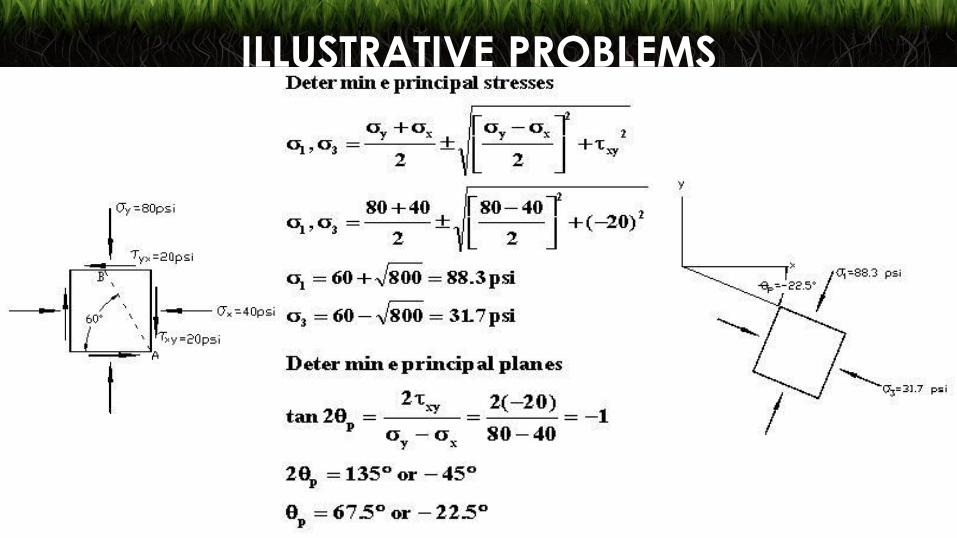
ILLUSTRATIVE PROBLEMS Shear and normal stresses are given on horizontal and vertical planes. Determine the following: Shear and normal stresses on plane AB
Principal stresses
Principal planes
ILLUSTRATIVE PROBLEMS

ILLUSTRATIVE PROBLEMS Shear and normal stresses are given on horizontal and vertical planes. Determine the following using the Mohr’s circle of stresses: Shear and normal stresses on plane AB
Principal stresses
Principal planes
Plot the stress state for the horizontal plane (80 psi, 20 psi)
Plot the stress state for the vertical plane (40 psi, -20 psi)
Draw a circle through these two points with the center on the x-axis
Determine the coordinates of the center of the circle
Determine the radius of the circle

ILLUSTRATIVE PROBLEMS Construct the Mohr’s circle and calculate the radius and center coordinates.

ILLUSTRATIVE PROBLEMS Determine the shear and normal stresses on plane AB.

ILLUSTRATIVE PROBLEMS Determine principal stresses and principal planes.

MOHR’S CIRCLE OF STRESSES Pole (Origin of Planes) of Mohr’s Circle
Pole Method of Finding Stresses on a Plane
1. Each stress state at one point on a plane is represented by a point M on the
Mohr’s circle.
2. From that point, draw a parallel to the plane on which the stresses act (σ, τ).
The intersection with the Mohr’s circle is called the pole point ‘P’.
3. To know the stresses acting on a plane EF, draw a parallel to the plane EF
from the pole point. The intersection with the circle gives point Q. This point Q
represents the stress state on EF.
4. The major and minor principal stresses σ1 and σ3 are found at the intersection
with the σ axis (by definition, a principal stress is a stress having only a normal
component).

MOHR’S CIRCLE OF STRESSES Pole (Origin of Planes) of Mohr’s Circle

Problem Set 10 Problem 1 Given an element with stresses as indicated in the figure, find: 1.1 The major and minor principal stresses and the
planes on which they act. (113.15 kPa, 6.85 kPa)
1.2 The stresses on a plane inclined at 300 from the
horizontal. (49.69 kPa, 52. 14 kPa)
1.3 The maximum shear stress and the inclination of
the plane on which it acts. (53.15 kPa, 24.41 degrees)

Problem Set 10 Solve Problem 1 with the element rotated 300 clockwise from the horizontal.
Problem 2

Problem Set 10 Given an element rotated 300 clockwise from the horizontal, find the stresses (magnitude and direction) on the horizontal plane. Also determine the principal stresses and planes and maximum shear stress.
Problem 3

Problem Set 10 For the element shown in the figure, find: 4.1 The magnitude of the unknown stresses 𝜎ℎ and 𝜏ℎ
on the horizontal plane. (1.3 kPa, 0)
4.2 The orientation of the principal stresses.
4.3 The orientation of the planes of maximum as well
as minimum shear.
Problem 4
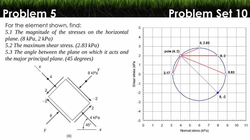
Problem Set 10 For the element shown, find: 5.1 The magnitude of the stresses on the horizontal
plane. (8 kPa, 2 kPa)
5.2 The maximum shear stress. (2.83 kPa)
5.3 The angle between the plane on which it acts and
the major principal plane. (45 degrees)
Problem 5