Embed Size (px)
Citation preview
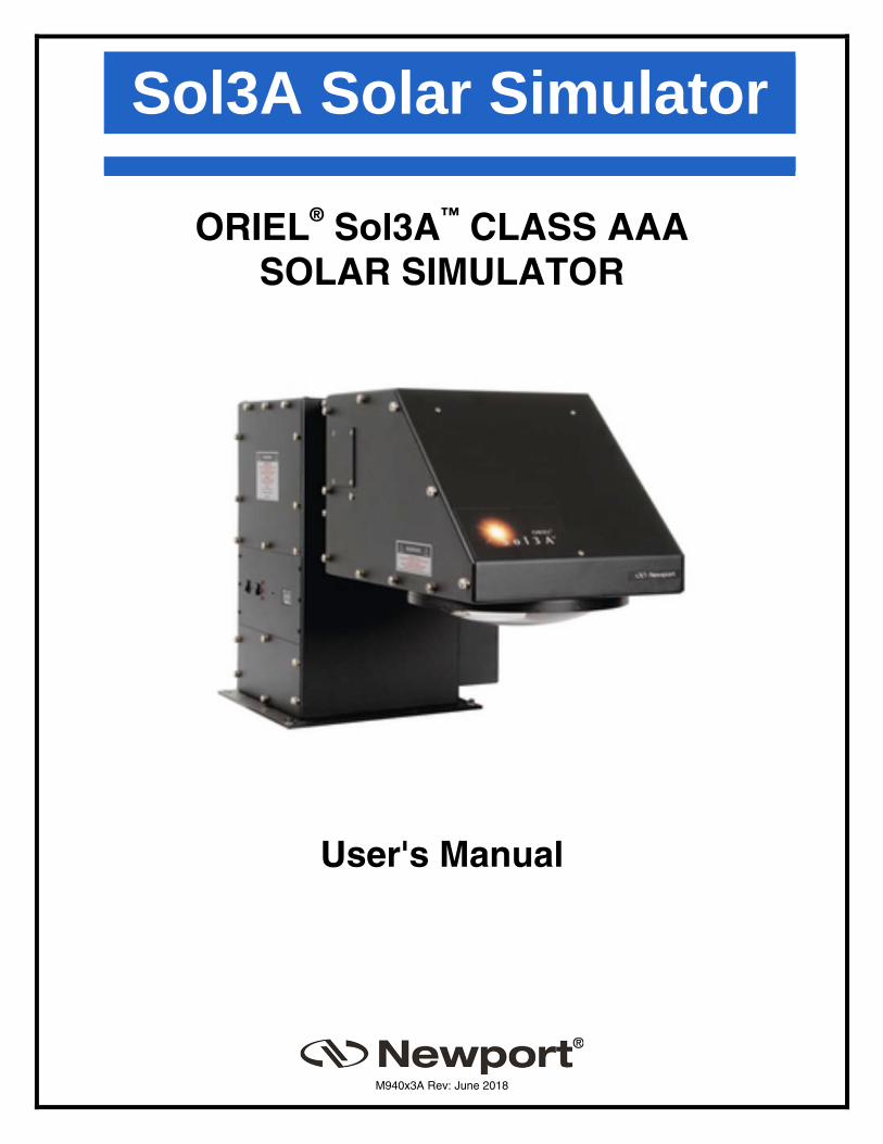
M940x3A Rev: June 2018
ORIEL® Sol3A™ CLASS AAA SOLAR SIMULATOR
User's Manual
Sol3A Solar Simulator

Sol3A Series Solar Simulator Systems
2
TABLE OF CONTENTS 1 INTRODUCTION .................................................................................................................................... 4 2 FEATURES AND SPECIFICATIONS ..................................................................................................... 5
2.1 Components Included ................................................................................................................. 5 2.2 Electrical Specifications .............................................................................................................. 5 2.3 Performance Specifications ........................................................................................................ 6
3 SAFETY .................................................................................................................................................. 8 3.1 Electrical Hazards ....................................................................................................................... 8 3.2 Ultraviolet Radiation Hazards ...................................................................................................... 8 3.3 Ozone .......................................................................................................................................... 9 3.4 Lamp Hazards ............................................................................................................................. 9 3.5 EMI ............................................................................................................................................ 10
4 SETTING UP THE SYSTEM ................................................................................................................ 11 4.1 Unpacking the System .............................................................................................................. 11 4.2 Mounting the System ................................................................................................................ 13 4.3 Installing the Filter(s) ................................................................................................................. 15 4.4 Operation Guide for Partial Sun Attenuator .............................................................................. 19 4.5 Lamp Access / Removing Panels ............................................................................................. 22 4.6 Installing the Lamp .................................................................................................................... 23
4.6.1 Installing the 450W Lamp ......................................................................................... 23 4.6.2 Installing the 1.0kW Lamp......................................................................................... 24 4.6.3 Installing the 1.6 kW Lamp ....................................................................................... 25
4.7 Electrical Connections ............................................................................................................... 26 4.8 Illuminator Housing Controls ..................................................................................................... 27
5 USING THE SYSTEM .......................................................................................................................... 28 5.1 Setting Up the Power Supply .................................................................................................... 28 5.2 Shutter Control .......................................................................................................................... 28 5.3 Starting the Lamp ...................................................................................................................... 28 5.4 Power Supply and Digital Exposure System ............................................................................. 28
6 ROUTINE MAINTENANCE .................................................................................................................. 29 6.1 Lamp Replacement ................................................................................................................... 29 6.2 Lamp Alignment ........................................................................................................................ 33 6.3 Cleaning Optics ......................................................................................................................... 35
7 TROUBLESHOOTING ......................................................................................................................... 36 8 WARRANTY AND RETURNS .............................................................................................................. 38
8.1 Contacting Oriel Instruments ..................................................................................................... 38 8.2 Request for Assistance / Service .............................................................................................. 39 8.3 Repair Service ........................................................................................................................... 39 8.4 Non-Warranty Repair ................................................................................................................ 40 8.5 Warranty Repair ........................................................................................................................ 40 8.6 Loaner / Demo Material ............................................................................................................. 41
9 PRODUCTS AND ACCESSORIES ...................................................................................................... 42 10 APPENDIX A: Dimensional and Mounting Diagrams ........................................................................... 43 11 APPENDIX B: Reports and Certifications ............................................................................................ 48
11.1 Non Uniformity Report ............................................................................................................... 48 11.2 Temporal Instability Report ....................................................................................................... 49 11.3 Spectral Match Report .............................................................................................................. 50
FIGURES Figure 1: Performance Validation Certificate for ORIEL® Sol3A™ .............................................................. 7 Figure 2: Installing the 450W Lamp ............................................................................................................ 23 Figure 3: Lamp Assembly for 1kW Lamp .................................................................................................... 24 Figure 4: Installing the 1.6kW Lamp ........................................................................................................... 25
Sol3A Series Solar Simulator Systems
3
Figure 5: 2x2 System (94023A) .................................................................................................................. 43 Figure 6: Base Plate Mounting Hole Locations Relative to Optical Centerline for 2x2 system .................. 43 Figure 7: 4x4 System (94043A) .................................................................................................................. 44 Figure 8: Base Plate Mounting Hole Locations Relative to Optical Centerline for 4x4 system .................. 44 Figure 9: 6x6 System (94063A) .................................................................................................................. 45 Figure 10: Base Plate Mounting Hole Locations Relative to Optical Centerline for 6x6 system ................ 45 Figure 11: 8x8 System (94083A) ................................................................................................................ 46 Figure 12: Base Plate Mounting Hole Locations Relative to Optical Centerline for 8x8 system ................ 46 Figure 13:12x12 System (94123A and 94123A-CPV) ................................................................................ 47 Figure 14: Base Plate Mounting Hole Locations Relative to Optical Centerline for 12x12 system ............ 47
PHOTOS Photo 1: Sol3A™ Solar Simulator and Power Supply .................................................................................. 5 Photo 2: Lamp and heat sink (with packing crate) ...................................................................................... 11 Photo 3: Air mass filter assembly (stored in case) ...................................................................................... 12 Photo 4: Unpacked components ................................................................................................................. 12 Photo 5: Simulator and power supply unpacked......................................................................................... 12 Photo 6: Risers for models 94023A and 94083A, respectively ................................................................... 13 Photo 7: Filter installed 6x6, 8x8 and 12x12 models .................................................................................. 15 Photo 8: Filter Installed 2x2 and 4x4 models .............................................................................................. 15 Photo 9: Proper installation placement of air mass filters for various models ............................................ 15 Photo 10: Output assembly, side cover removed ....................................................................................... 16 Photo 11: Removing the lamp access panel ............................................................................................... 22 Photo 12: Lamp access panel removed ...................................................................................................... 22 Photo 13: 450W Lamp with heat sink attached ........................................................................................... 23 Photo 14: 1kW lamp with heat sink attached .............................................................................................. 24 Photo 15: 1.6kW lamp with heat sink attached ........................................................................................... 25 Photo 16: Electrical connections on simulator (black and gray cables) ...................................................... 26 Photo 17: Electrical connections on power supply (black and gray cables) ............................................... 26 Photo 18: The illuminator housing control panel ......................................................................................... 27 Photo 19: The Illuminator (rear view) .......................................................................................................... 29 Photo 20: Removing the lamp access panel ............................................................................................... 29 Photo 21: Lamp access panel removed ...................................................................................................... 30 Photo 22: #10-32 thumb nut on heat sink ................................................................................................... 30 Photo 23: Removing the high voltage lead from the heat sink. .................................................................. 31 Photo 24: Heat sink unscrewed from socket ............................................................................................... 31 Photo 25: Heat sink and lamp removed ...................................................................................................... 32 Photo 26: Lamp focus adjustment mechanisms (Access panel removed) ................................................. 33 Photo 27: Adjustment using the ladder chain ............................................................................................. 34 Photo 28: Adjustment using the X-Y knobs ................................................................................................ 34 Photo 29: Lamp run under reverse polarity ................................................................................................. 37
TABLES Table 1: Model Information ........................................................................................................................... 4 Table 2: Performance Specifications ............................................................................................................ 6 Table 3: Riser Assemblies .......................................................................................................................... 13 Table 4: Newport Breadboard Mount Solutions .......................................................................................... 14 Table 5: Air Mass Filters ............................................................................................................................. 16 Table 6: Partial Sun Attenuator Effects on Beam Uniformity ...................................................................... 21 Table 7: Troubleshooting Guide .................................................................................................................. 37 Table 8: Products and Accessories ............................................................................................................ 42
Sol3A Series Solar Simulator Systems
4
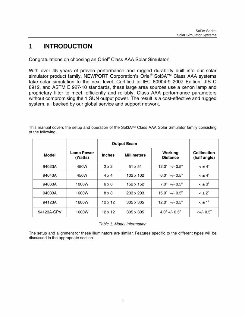
1 INTRODUCTION Congratulations on choosing an Oriel® Class AAA Solar Simulator! With over 45 years of proven performance and rugged durability built into our solar simulator product family, NEWPORT Corporation’s Oriel® Sol3A™ Class AAA systems take solar simulation to the next level. Certified to IEC 60904-9 2007 Edition, JIS C 8912, and ASTM E 927-10 standards, these large area sources use a xenon lamp and proprietary filter to meet, efficiently and reliably, Class AAA performance parameters without compromising the 1 SUN output power. The result is a cost-effective and rugged system, all backed by our global service and support network. This manual covers the setup and operation of the Sol3A™ Class AAA Solar Simulator family consisting of the following:
Output Beam
Model Lamp Power (Watts)
Inches Millimeters Working Distance
Collimation (half angle)
94023A 450W 2 x 2 51 x 51 12.0” +/- 0.5” < ± 4o
94043A 450W 4 x 4 102 x 102 6.0” +/- 0.5” < ± 4o
94063A 1000W 6 x 6 152 x 152 7.0” +/- 0.5” < ± 3o
94083A 1600W 8 x 8 203 x 203 15.0” +/- 0.5” < ± 2o
94123A 1600W 12 x 12 305 x 305 12.0” +/- 0.5” < ± 1o
94123A-CPV 1600W 12 x 12 305 x 305 4.0” +/- 0.5” <+/- 0.50
Table 1: Model Information
The setup and alignment for these illuminators are similar. Features specific to the different types will be discussed in the appropriate section.
Sol3A Series Solar Simulator Systems
5
2 FEATURES AND SPECIFICATIONS
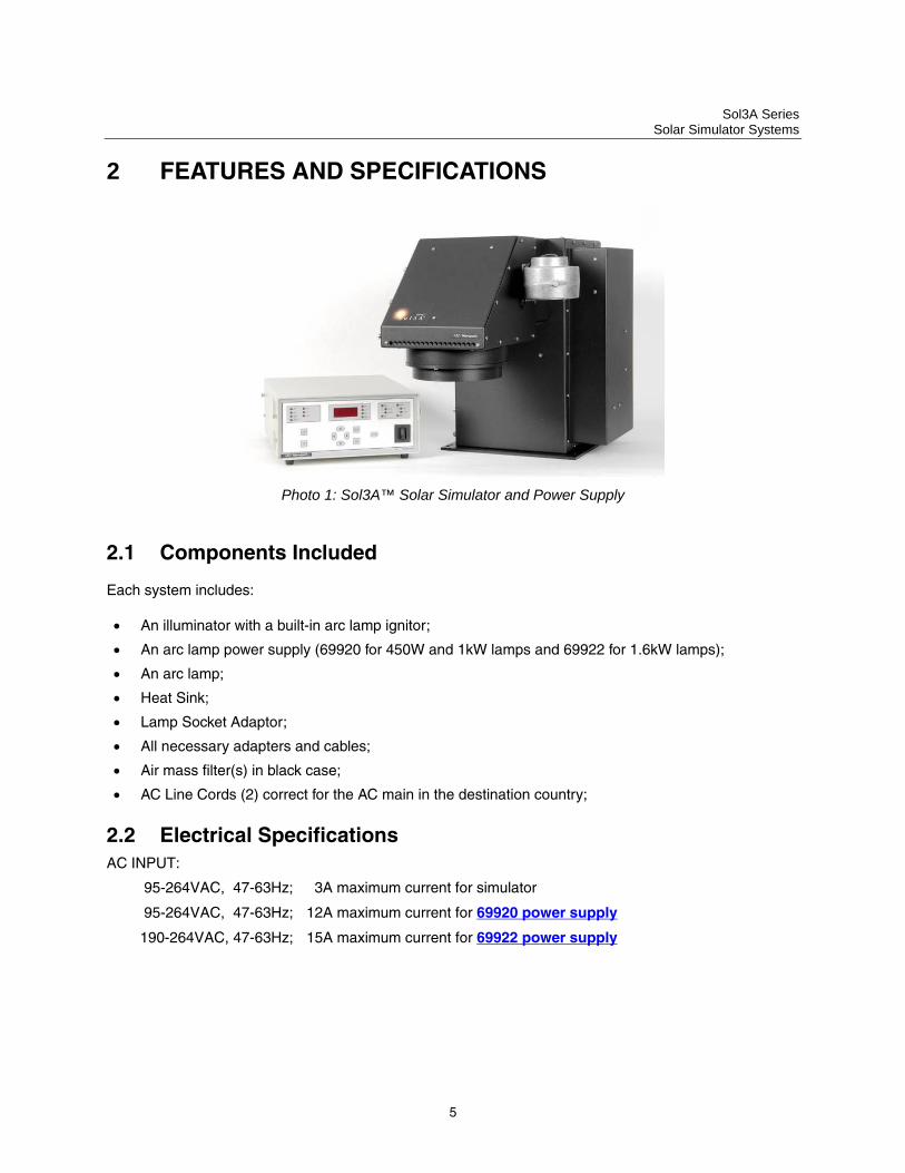
Photo 1: Sol3A™ Solar Simulator and Power Supply
2.1 Components Included
Each system includes: An illuminator with a built-in arc lamp ignitor;
An arc lamp power supply (69920 for 450W and 1kW lamps and 69922 for 1.6kW lamps);
An arc lamp;
Heat Sink;
Lamp Socket Adaptor;
All necessary adapters and cables;
Air mass filter(s) in black case;
AC Line Cords (2) correct for the AC main in the destination country;
2.2 Electrical Specifications AC INPUT:
95-264VAC, 47-63Hz; 3A maximum current for simulator
95-264VAC, 47-63Hz; 12A maximum current for 69920 power supply
190-264VAC, 47-63Hz; 15A maximum current for 69922 power supply
Sol3A Series Solar Simulator Systems
6
2.3 Performance Specifications
Sol3A Performance
IEC 60904-9 ED2
Class A
JIS
Class A
ASTM
Class A
SPECTRAL MATCH1 ALL MODELS Class AAA
0.75-1.25% FRACTION OF IDEAL
PERCENTAGE
0.75-1.25% FRACTION OF IDEAL
PERCENTAGE
0.75-1.25% FRACTION OF IDEAL
PERCENTAGE
NON-UNIFORMITY OF IRRADIANCE2 ALL MODELS Class AAA <2.0% ± 2% 2%
TEMPORAL INSTABILITY3 ALL MODELS Class AAA
<0.5% short term
instability (STI)
<2.0% Long Term
Instability (LTI)
± 1% ± 2%
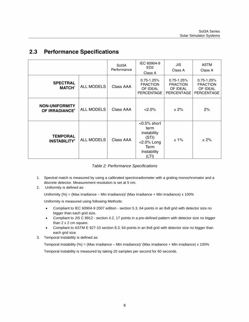
Table 2: Performance Specifications
1. Spectral match is measured by using a calibrated spectroradiometer with a grating monochromator and a discrete detector. Measurement resolution is set at 5 nm.
2. Uniformity is defined as:
Uniformity (%) = (Max irradiance – Min irradiance)/ (Max irradiance + Min irradiance) x 100%
Uniformity is measured using following Methods:
Compliant to IEC 60904-9 2007 edition - section 5.3, 64 points in an 8x8 grid with detector size no bigger than each grid size.
Compliant to JIS C 8912 - section 4.2, 17 points in a pre-defined pattern with detector size no bigger than 2 x 2 cm square.
Compliant to ASTM E 927-10 section 8.3, 64 points in an 8x8 grid with detector size no bigger than each grid size.
3. Temporal Instability is defined as:
Temporal Instability (%) = (Max irradiance – Min irradiance)/ (Max irradiance + Min irradiance) x 100%
Temporal instability is measured by taking 20 samples per second for 60 seconds.
Sol3A Series Solar Simulator Systems
7
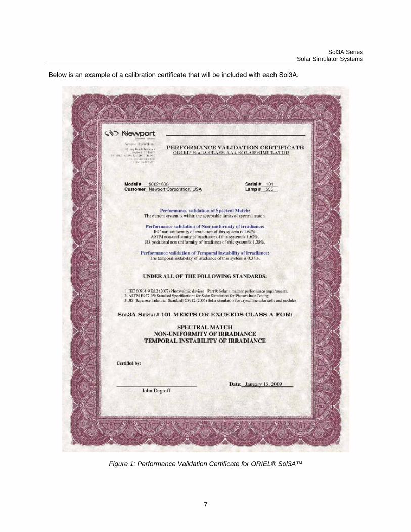
Below is an example of a calibration certificate that will be included with each Sol3A.
Figure 1: Performance Validation Certificate for ORIEL® Sol3A™
Sol3A Series Solar Simulator Systems
8
3 SAFETY
3.1 Electrical Hazards There is no hazard during normal operation. Normal operation means that the power supply and illuminator are operated at the specified current and voltage, with their covers properly in place and all cables correctly connected.
Incorrect connection of the cables is hazardous to the equipment and can result in violent lamp explosion!
The power supply provides voltages and currents that could be lethal. Do not operate the power supply unless it and the illuminator are properly cabled. Do not remove the power supply cover and turn it on! The power supply cover should only be removed by a qualified electronics technician experienced with high-voltage power supplies. The illuminator produces very high internal voltages. A transient ignition pulse of several kilovolts is used to start the lamp. This voltage, under certain circumstances, could be lethal. The illuminator is equipped with an interlock switching system.
DO NOT attempt to circumvent this system.
DO NOT operate the illuminator with any access to the interior of the housing. For complete instructions on proper operation, read all of this manual as well as the Power Supply Manuals (69920 for use with 450W and 1KW and the 69922 for use with the 1.6 KW).
3.2 Ultraviolet Radiation Hazards This unit produces high intensity ultraviolet (UV) radiation. This radiation can cause severe burns to skin and the outer layers of the eye which may not become apparent for hours or even days after the exposure. As with sunlight, there is a risk of melanoma (skin cancer) as well as the formation of cataracts with repeated exposure.
DO NO OPERATE THIS EQUIPMENT UNTIL YOU HAVE READ THIS MANUAL!
THE HAZARDS ASSOCIATED WITH THE OPERATION OF THIS EQUIPMENT FALL INTO THE FOLLOWING FOUR CATEGORIES:
ELECTRICAL HAZARDS
ULTRAVIOLET RADIATION HAZARDS
LAMP HAZARDS
AND TRANSIENT EMI HAZARDS
DURING NORMAL OPERATION AND IN ACCORDANCE WITH THE PRECAUTIONS PRESENTED IN THIS MANUAL, NONE OF THESE HAZARDS PRESENT A PROBLEM.
Sol3A Series Solar Simulator Systems
9
Under normal operating conditions, the user receives minimal UV exposure even over long periods of operation. However, certain precautions should always be taken when operating this equipment: Always avoid exposure to the direct, reflected, or diffuse radiation from the lamp or the unit itself. Always wear UV-blocking glasses, goggles or other face shielding during operation. Always wear protective clothing and gloves if it is necessary to be exposed to the direct beam, even
if only for a few seconds. For a list of Newport-recommended UV protection solutions, please refer to Table 8.
3.3 Ozone Ultraviolet light reacts on a molecular level with the atmosphere to produce ozone that is vented from the housing during normal operation by the cooling fans. When this exhaust is vented into an enclosed area, the ozone concentration can build up beyond the recommended 1 ppm exposure level. Ozone is considered toxic and can induce headaches, nausea, and flu-like symptoms. For people with chronic respiratory conditions such as asthma, extremely high levels of ozone can pose a serious health hazard. Susceptibility varies significantly from individual to individual. Fortunately, ozone has a distinctive odor. If this smell is noticed persistently in an area remote from the fans, it is recommended to check the ozone levels with a test kit and improve the ventilation of the area. It is the user’s responsibility to ensure that the equipment is operated in an area with adequate ventilation or provide other means for eliminating excessive levels of ozone, such as an Oriel model 66087 Ozone Eater or direct outside exhaust
3.4 Lamp Hazards The arc lamps used in this illuminator are filled with rare gas at high pressure. There is always a danger of lamp explosion due to mechanical failure. This is particularly true when the lamp is operating, since the internal pressure can reach tens of atmospheres. Thermal strains can cause the lamp to explode under certain conditions.
Never touch the lamp with bare fingers or other contaminates. Skin oil or other substances can burn into the lamp envelope and weaken its structure.
Always wear appropriate gloves and impact-resistant goggles when handling the lamp.
Avoid any mechanical strain during handling.
DO NOT operate the lamp unless all housing panels are in place.
Arc lamps become very hot (up to 220°C) after only a few minutes of operation, and remain quite
hot for at least 25-30 minutes after being turned off.
If the Arc Lamp is turned off, do not attempt to restart the lamp until the lamp has completely cooled. Lamp life may be significantly reduced by failure to adequately cool it.
Sol3A Series Solar Simulator Systems
10
3.5 EMI
Ignition of an arc lamp requires a high voltage pulse. This pulse is a source of electromagnetic interference (EMI) - both radiated and conducted. Good grounding, cable routing practice, and EMI shielding may be necessary to protect sensitive circuitry from this ignition pulse.
It is suggested to start the arc lamp before powering up nearby computer equipment. Keep computers and other sensitive electronic devices at least six feet (1.8 meters) away from the light source.
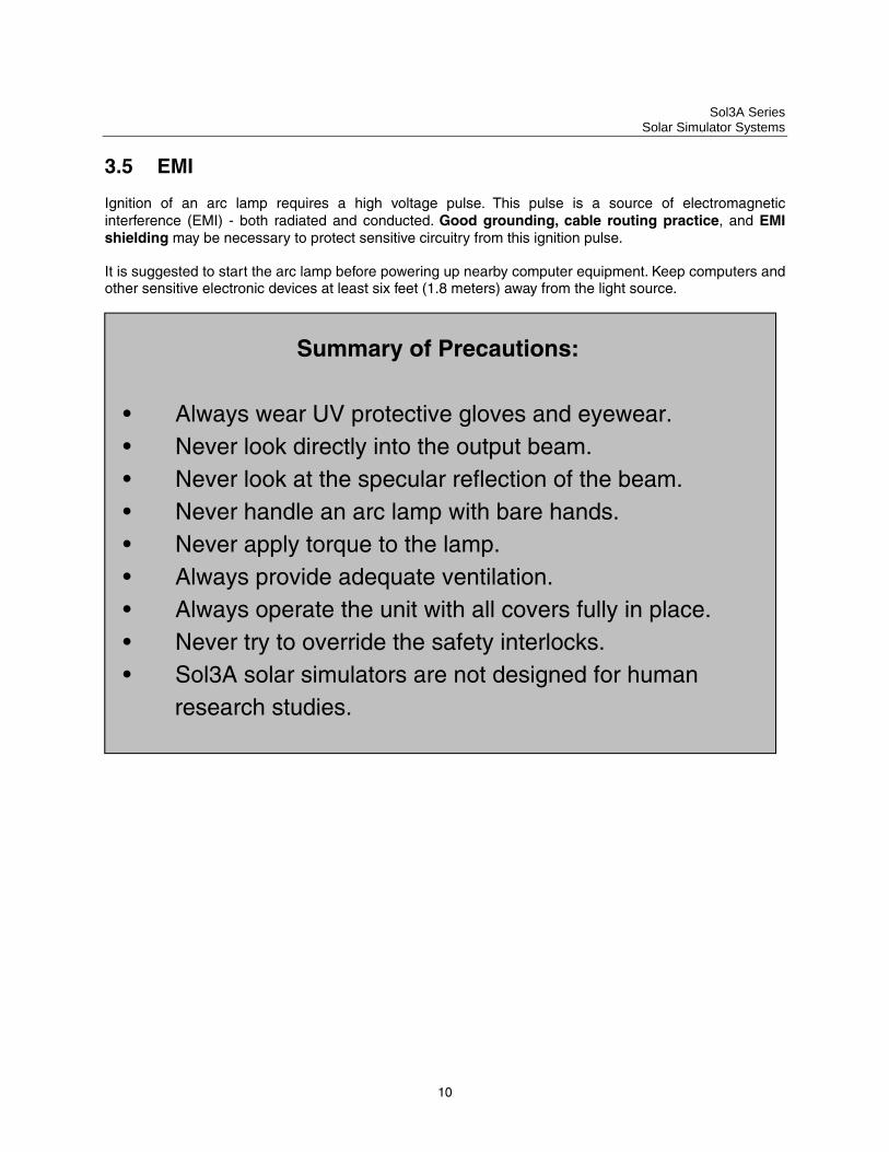
Summary of Precautions:
• Always wear UV protective gloves and eyewear.• Never look directly into the output beam.• Never look at the specular reflection of the beam.• Never handle an arc lamp with bare hands.• Never apply torque to the lamp.• Always provide adequate ventilation.• Always operate the unit with all covers fully in place.• Never try to override the safety interlocks.• Sol3A solar simulators are not designed for human research studies.
Sol3A Series Solar Simulator Systems
11
4 SETTING UP THE SYSTEM
4.1 Unpacking the System
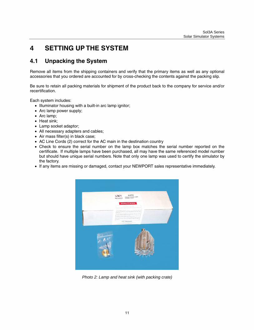
Remove all items from the shipping containers and verify that the primary items as well as any optional accessories that you ordered are accounted for by cross-checking the contents against the packing slip.
Be sure to retain all packing materials for shipment of the product back to the company for service and/or recertification.
Each system includes: Illuminator housing with a built-in arc lamp ignitor; Arc lamp power supply; Arc lamp; Heat sink; Lamp socket adaptor; All necessary adapters and cables; Air mass filter(s) in black case; AC Line Cords (2) correct for the AC main in the destination country Check to ensure the serial number on the lamp box matches the serial number reported on the
certificate. If multiple lamps have been purchased, all may have the same referenced model numberbut should have unique serial numbers. Note that only one lamp was used to certify the simulator bythe factory.
If any items are missing or damaged, contact your NEWPORT sales representative immediately.
Photo 2: Lamp and heat sink (with packing crate)
Sol3A Series Solar Simulator Systems
12
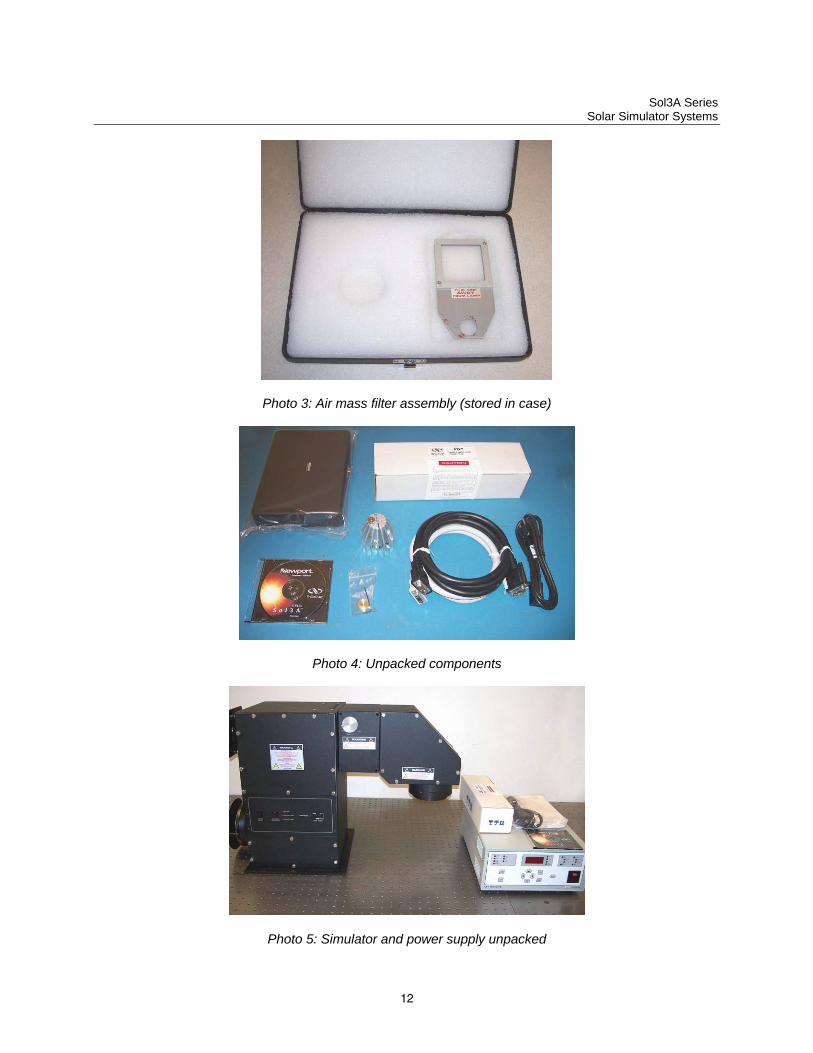
Photo 3: Air mass filter assembly (stored in case)
Photo 4: Unpacked components
Photo 5: Simulator and power supply unpacked
Sol3A Series Solar Simulator Systems
13
4.2 Mounting the System
When removing the Sol3A from the crate be careful when placing it on a surface as it has a center of gravity shifted to the front of the unit and can easily tip. Be certain to support the unit temporarily until it is permanently mounted to a work surface.
See Appendix A for dimensional drawings to determine how your Sol3A solar simulator will be mounted to accommodate your test fixture.
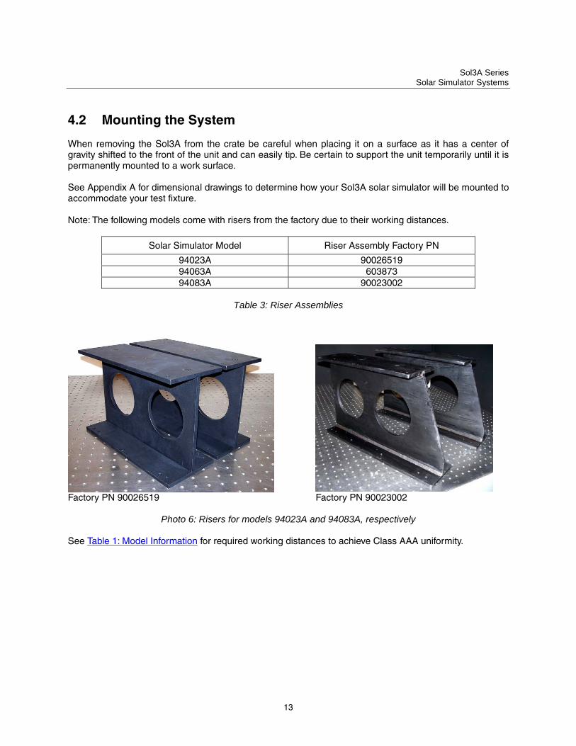
Note: The following models come with risers from the factory due to their working distances.
Solar Simulator Model Riser Assembly Factory PN
94023A 9002651994063A 60387394083A 90023002
Table 3: Riser Assemblies
Factory PN 90026519 Factory PN 90023002
Photo 6: Risers for models 94023A and 94083A, respectively
See Table 1: Model Information for required working distances to achieve Class AAA uniformity.
Sol3A Series Solar Simulator Systems
14
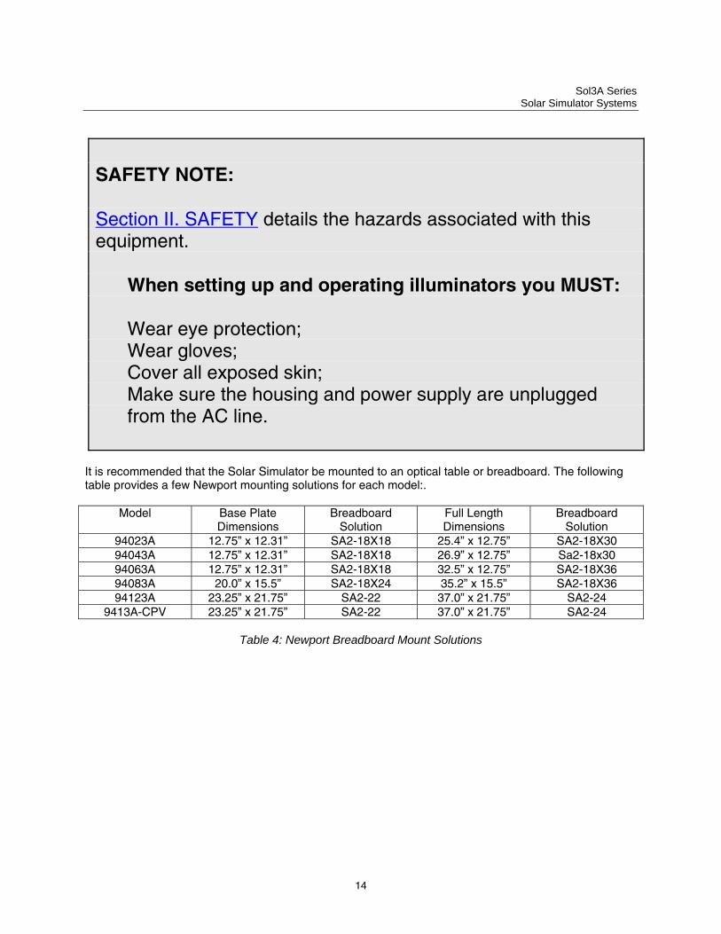
SAFETY NOTE:
Section II. SAFETY details the hazards associated with this equipment.
When setting up and operating illuminators you MUST:
Wear eye protection; Wear gloves; Cover all exposed skin; Make sure the housing and power supply are unplugged from the AC line.
It is recommended that the Solar Simulator be mounted to an optical table or breadboard. The following table provides a few Newport mounting solutions for each model:.
Model Base PlateDimensions
Breadboard Solution
Full Length Dimensions
Breadboard Solution
94023A 12.75” x 12.31” SA2-18X18 25.4” x 12.75” SA2-18X30 94043A 12.75” x 12.31” SA2-18X18 26.9” x 12.75” Sa2-18x30 94063A 12.75” x 12.31” SA2-18X18 32.5” x 12.75” SA2-18X36 94083A 20.0” x 15.5” SA2-18X24 35.2” x 15.5” SA2-18X3694123A 23.25” x 21.75” SA2-22 37.0” x 21.75” SA2-24
9413A-CPV 23.25” x 21.75” SA2-22 37.0” x 21.75” SA2-24
Table 4: Newport Breadboard Mount Solutions
Sol3A Series Solar Simulator Systems
15
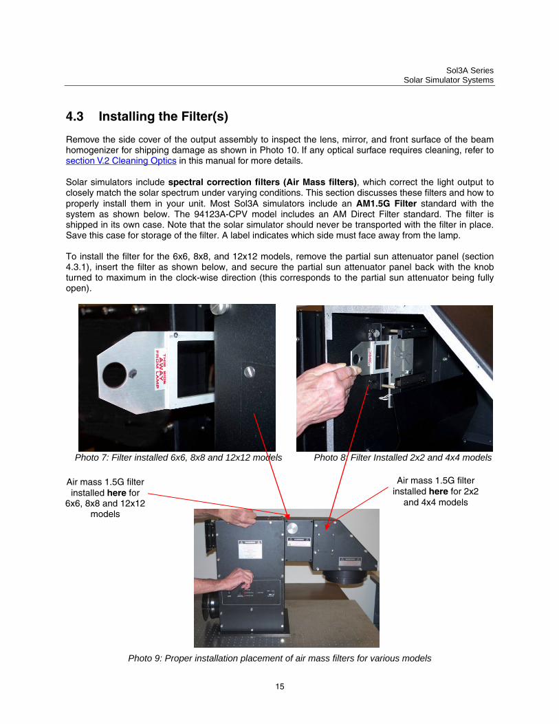
4.3 Installing the Filter(s)
Remove the side cover of the output assembly to inspect the lens, mirror, and front surface of the beam homogenizer for shipping damage as shown in Photo 10. If any optical surface requires cleaning, refer to section V.2 Cleaning Optics in this manual for more details.
Solar simulators include spectral correction filters (Air Mass filters), which correct the light output to closely match the solar spectrum under varying conditions. This section discusses these filters and how to properly install them in your unit. Most Sol3A simulators include an AM1.5G Filter standard with the system as shown below. The 94123A-CPV model includes an AM Direct Filter standard. The filter is shipped in its own case. Note that the solar simulator should never be transported with the filter in place. Save this case for storage of the filter. A label indicates which side must face away from the lamp.
To install the filter for the 6x6, 8x8, and 12x12 models, remove the partial sun attenuator panel (section 4.3.1), insert the filter as shown below, and secure the partial sun attenuator panel back with the knob turned to maximum in the clock-wise direction (this corresponds to the partial sun attenuator being fully open).
Photo 7: Filter installed 6x6, 8x8 and 12x12 models Photo 8: Filter Installed 2x2 and 4x4 models
Photo 9: Proper installation placement of air mass filters for various models
Air mass 1.5G filter installed here for 2x2
and 4x4 models
Air mass 1.5G filter installed here for
6x6, 8x8 and 12x12 models
Sol3A Series Solar Simulator Systems
16
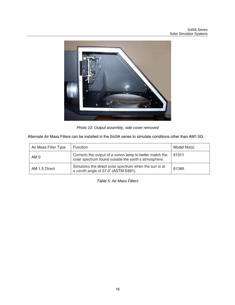
Photo 10: Output assembly, side cover removed
Alternate Air Mass Filters can be installed in the Sol3A series to simulate conditions other than AM1.5G.
Air Mass Filter Type Function Model No(s).
AM 0 Corrects the output of a xenon lamp to better match the solar spectrum found outside the earth’s atmosphere.
81311
AM 1.5 Direct Simulates the direct solar spectrum when the sun is at a zenith angle of 37.00 (ASTM E891). 81389
Table 5: Air Mass Filters
Sol3A Series Solar Simulator Systems
17
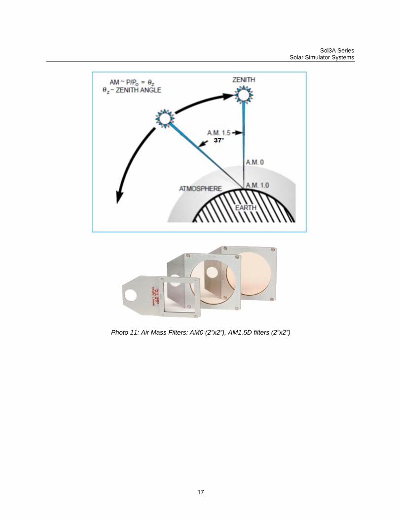
Photo 11: Air Mass Filters: AM0 (2”x2”), AM1.5D filters (2”x2”)
Sol3A Series Solar Simulator Systems
18
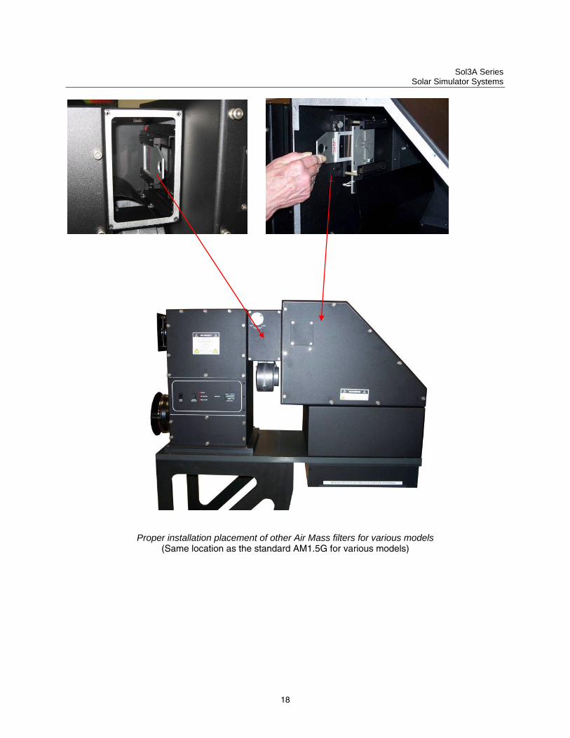
Proper installation placement of other Air Mass filters for various models (Same location as the standard AM1.5G for various models)
Sol3A Series Solar Simulator Systems
19
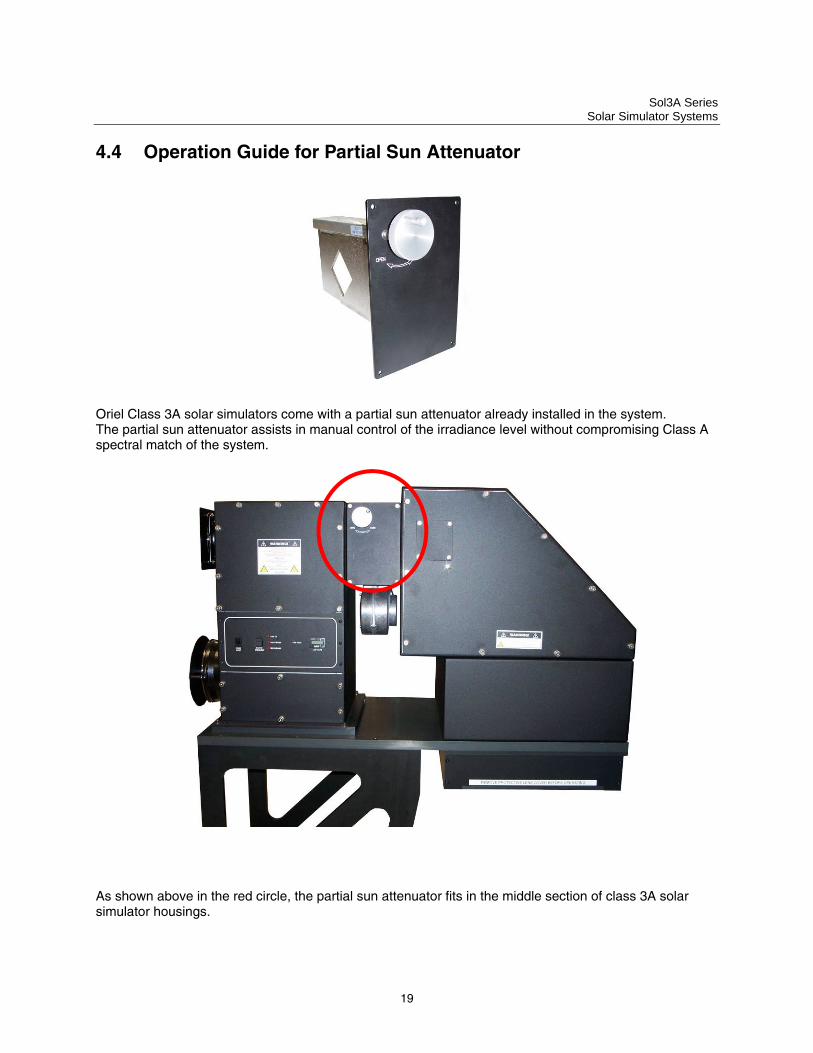
4.4 Operation Guide for Partial Sun Attenuator
Oriel Class 3A solar simulators come with a partial sun attenuator already installed in the system. The partial sun attenuator assists in manual control of the irradiance level without compromising Class A spectral match of the system.
As shown above in the red circle, the partial sun attenuator fits in the middle section of class 3A solar simulator housings.
Sol3A Series Solar Simulator Systems
20
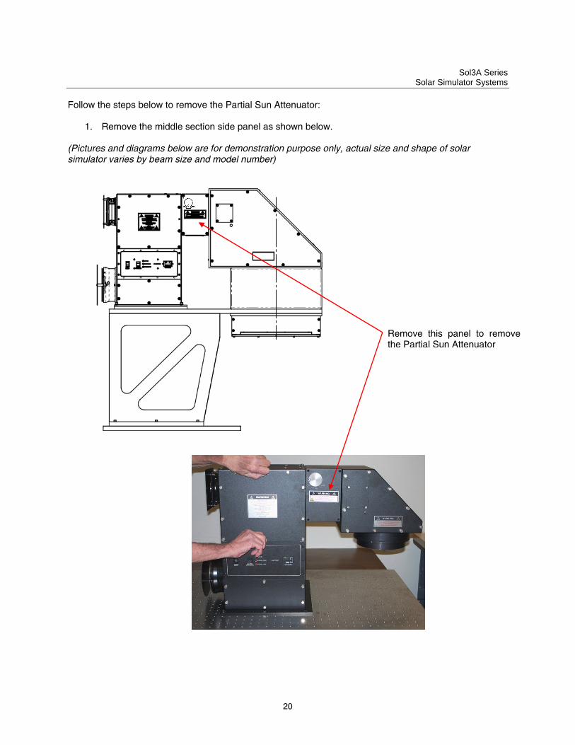
Follow the steps below to remove the Partial Sun Attenuator:
1. Remove the middle section side panel as shown below.
(Pictures and diagrams below are for demonstration purpose only, actual size and shape of solar simulator varies by beam size and model number)
Remove this panel to remove the Partial Sun Attenuator
Sol3A Series Solar Simulator Systems
21
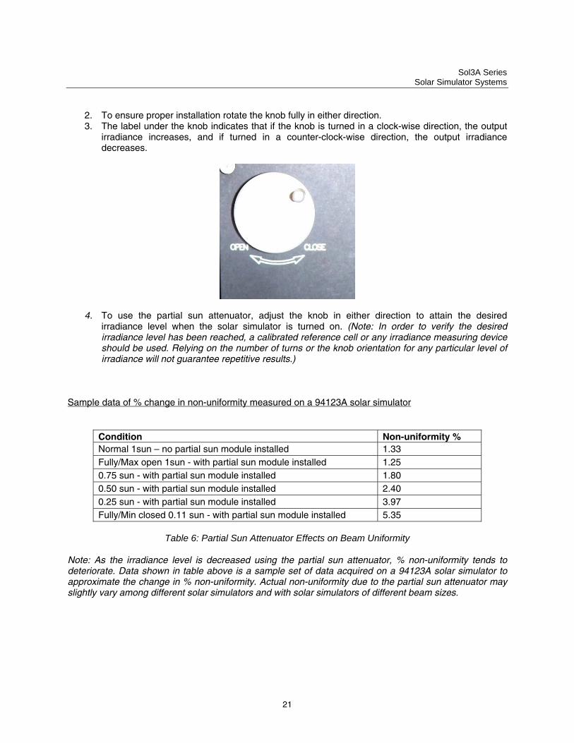
2. To ensure proper installation rotate the knob fully in either direction. 3. The label under the knob indicates that if the knob is turned in a clock-wise direction, the output
irradiance increases, and if turned in a counter-clock-wise direction, the output irradiance decreases.
4. To use the partial sun attenuator, adjust the knob in either direction to attain the desired
irradiance level when the solar simulator is turned on. (Note: In order to verify the desired irradiance level has been reached, a calibrated reference cell or any irradiance measuring device should be used. Relying on the number of turns or the knob orientation for any particular level of irradiance will not guarantee repetitive results.)
Sample data of % change in non-uniformity measured on a 94123A solar simulator
Condition Non-uniformity % Normal 1sun – no partial sun module installed 1.33 Fully/Max open 1sun - with partial sun module installed 1.25 0.75 sun - with partial sun module installed 1.80 0.50 sun - with partial sun module installed 2.40 0.25 sun - with partial sun module installed 3.97 Fully/Min closed 0.11 sun - with partial sun module installed 5.35
Table 6: Partial Sun Attenuator Effects on Beam Uniformity
Note: As the irradiance level is decreased using the partial sun attenuator, % non-uniformity tends to deteriorate. Data shown in table above is a sample set of data acquired on a 94123A solar simulator to approximate the change in % non-uniformity. Actual non-uniformity due to the partial sun attenuator may slightly vary among different solar simulators and with solar simulators of different beam sizes.
Sol3A Series Solar Simulator Systems
22
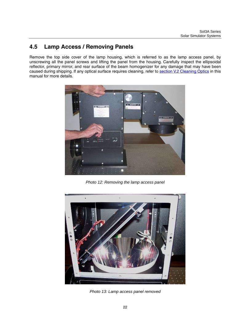
4.5 Lamp Access / Removing Panels
Remove the top side cover of the lamp housing, which is referred to as the lamp access panel, by unscrewing all the panel screws and lifting the panel from the housing. Carefully inspect the ellipsoidal reflector, primary mirror, and rear surface of the beam homogenizer for any damage that may have been caused during shipping. If any optical surface requires cleaning, refer to section V.2 Cleaning Optics in this manual for more details.
Photo 12: Removing the lamp access panel
Photo 13: Lamp access panel removed
Sol3A Series Solar Simulator Systems
23
4.6 Installing the Lamp
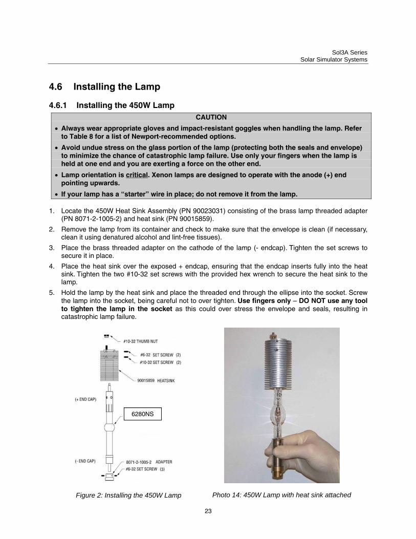
4.6.1 Installing the 450W Lamp CAUTION
Always wear appropriate gloves and impact-resistant goggles when handling the lamp. Refer to Table 8 for a list of Newport-recommended options.
Avoid undue stress on the glass portion of the lamp (protecting both the seals and envelope) to minimize the chance of catastrophic lamp failure. Use only your fingers when the lamp is held at one end and you are exerting a force on the other end.
Lamp orientation is critical. Xenon lamps are designed to operate with the anode (+) end pointing upwards.
If your lamp has a “starter” wire in place; do not remove it from the lamp. 1. Locate the 450W Heat Sink Assembly (PN 90023031) consisting of the brass lamp threaded adapter
(PN 8071-2-1005-2) and heat sink (PN 90015859).
2. Remove the lamp from its container and check to make sure that the envelope is clean (if necessary, clean it using denatured alcohol and lint-free tissues).
3. Place the brass threaded adapter on the cathode of the lamp (- endcap). Tighten the set screws to secure it in place.
4. Place the heat sink over the exposed + endcap, ensuring that the endcap inserts fully into the heat sink. Tighten the two #10-32 set screws with the provided hex wrench to secure the heat sink to the lamp.
5. Hold the lamp by the heat sink and place the threaded end through the ellipse into the socket. Screw the lamp into the socket, being careful not to over tighten. Use fingers only – DO NOT use any tool to tighten the lamp in the socket as this could over stress the envelope and seals, resulting in catastrophic lamp failure.
Figure 2: Installing the 450W Lamp
Photo 14: 450W Lamp with heat sink attached
6280NS
Sol3A Series Solar Simulator Systems
24
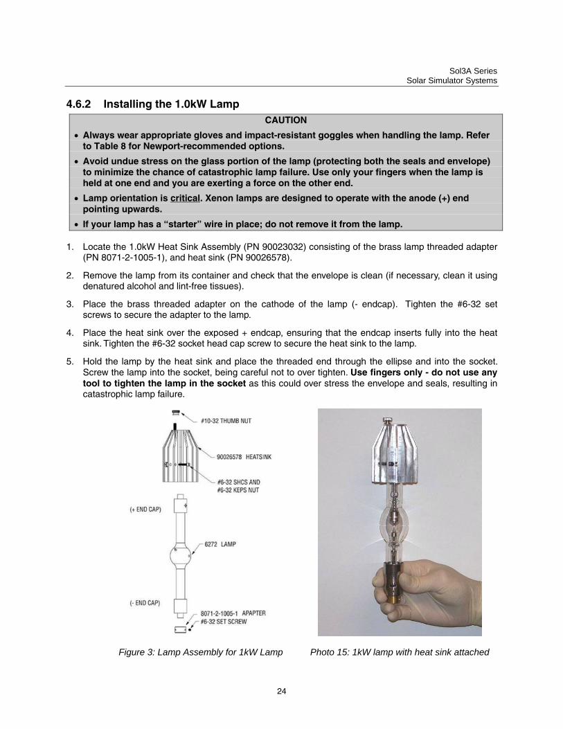
4.6.2 Installing the 1.0kW Lamp CAUTION
Always wear appropriate gloves and impact-resistant goggles when handling the lamp. Refer to Table 8 for Newport-recommended options.
Avoid undue stress on the glass portion of the lamp (protecting both the seals and envelope) to minimize the chance of catastrophic lamp failure. Use only your fingers when the lamp is held at one end and you are exerting a force on the other end.
Lamp orientation is critical. Xenon lamps are designed to operate with the anode (+) end pointing upwards.
If your lamp has a “starter” wire in place; do not remove it from the lamp. 1. Locate the 1.0kW Heat Sink Assembly (PN 90023032) consisting of the brass lamp threaded adapter
(PN 8071-2-1005-1), and heat sink (PN 90026578).
2. Remove the lamp from its container and check that the envelope is clean (if necessary, clean it using denatured alcohol and lint-free tissues).
3. Place the brass threaded adapter on the cathode of the lamp (- endcap). Tighten the #6-32 set screws to secure the adapter to the lamp.
4. Place the heat sink over the exposed + endcap, ensuring that the endcap inserts fully into the heat sink. Tighten the #6-32 socket head cap screw to secure the heat sink to the lamp.
5. Hold the lamp by the heat sink and place the threaded end through the ellipse and into the socket. Screw the lamp into the socket, being careful not to over tighten. Use fingers only - do not use any tool to tighten the lamp in the socket as this could over stress the envelope and seals, resulting in catastrophic lamp failure.
Figure 3: Lamp Assembly for 1kW Lamp
Photo 15: 1kW lamp with heat sink attached
Sol3A Series Solar Simulator Systems
25
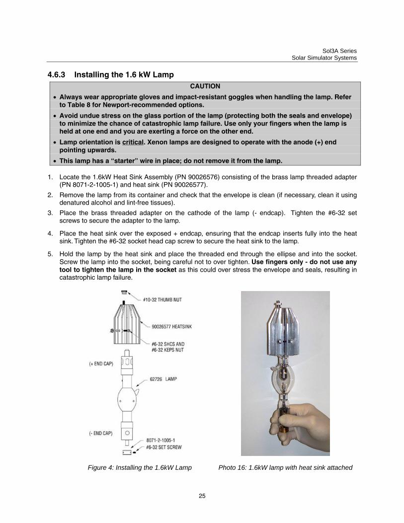
4.6.3 Installing the 1.6 kW Lamp CAUTION
Always wear appropriate gloves and impact-resistant goggles when handling the lamp. Refer to Table 8 for Newport-recommended options.
Avoid undue stress on the glass portion of the lamp (protecting both the seals and envelope) to minimize the chance of catastrophic lamp failure. Use only your fingers when the lamp is held at one end and you are exerting a force on the other end.
Lamp orientation is critical. Xenon lamps are designed to operate with the anode (+) end pointing upwards.
This lamp has a “starter” wire in place; do not remove it from the lamp. 1. Locate the 1.6kW Heat Sink Assembly (PN 90026576) consisting of the brass lamp threaded adapter
(PN 8071-2-1005-1) and heat sink (PN 90026577).
2. Remove the lamp from its container and check that the envelope is clean (if necessary, clean it using denatured alcohol and lint-free tissues).
3. Place the brass threaded adapter on the cathode of the lamp (- endcap). Tighten the #6-32 set screws to secure the adapter to the lamp.
4. Place the heat sink over the exposed + endcap, ensuring that the endcap inserts fully into the heat sink. Tighten the #6-32 socket head cap screw to secure the heat sink to the lamp.
5. Hold the lamp by the heat sink and place the threaded end through the ellipse and into the socket. Screw the lamp into the socket, being careful not to over tighten. Use fingers only - do not use any tool to tighten the lamp in the socket as this could over stress the envelope and seals, resulting in catastrophic lamp failure.
Figure 4: Installing the 1.6kW Lamp
Photo 16: 1.6kW lamp with heat sink attached
Sol3A Series Solar Simulator Systems
26
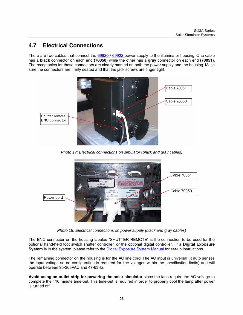
4.7 Electrical Connections There are two cables that connect the 69920 / 69922 power supply to the illuminator housing. One cable has a black connector on each end (70050) while the other has a gray connector on each end (70051). The receptacles for these connectors are clearly marked on both the power supply and the housing. Make sure the connectors are firmly seated and that the jack screws are finger tight.
Photo 17: Electrical connections on simulator (black and gray cables)
Photo 18: Electrical connections on power supply (black and gray cables)
The BNC connector on the housing labeled “SHUTTER REMOTE” is the connection to be used for the optional hand-held foot switch shutter controller, or the optional digital controller. If a Digital Exposure System is in the system, please refer to the Digital Exposure System Manual for set-up instructions. The remaining connector on the housing is for the AC line cord. The AC input is universal (it auto senses the input voltage so no configuration is required for line voltages within the specification limits) and will operate between 95-265VAC and 47-63Hz. Avoid using an outlet strip for powering the solar simulator since the fans require the AC voltage to complete their 10 minute time-out. This time-out is required in order to properly cool the lamp after power is turned off.
Sol3A Series Solar Simulator Systems
27
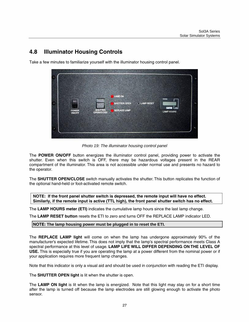
4.8 Illuminator Housing Controls Take a few minutes to familiarize yourself with the illuminator housing control panel.
Photo 19: The illuminator housing control panel The POWER ON/OFF button energizes the illuminator control panel, providing power to activate the shutter. Even when this switch is OFF, there may be hazardous voltages present in the REAR compartment of the illuminator. This area is not accessible under normal use and presents no hazard to the operator. The SHUTTER OPEN/CLOSE switch manually activates the shutter. This button replicates the function of the optional hand-held or foot-activated remote switch.
NOTE: If the front panel shutter switch is depressed, the remote input will have no effect. Similarly, if the remote input is active (TTL high), the front panel shutter switch has no effect.
The LAMP HOURS meter (ETI) indicates the cumulative lamp hours since the last lamp change.
The LAMP RESET button resets the ETI to zero and turns OFF the REPLACE LAMP indicator LED.
NOTE: The lamp housing power must be plugged in to reset the ETI.
The REPLACE LAMP light will come on when the lamp has undergone approximately 90% of the manufacturer’s expected lifetime. This does not imply that the lamp’s spectral performance meets Class A spectral performance at this level of usage. LAMP LIFE WILL DIFFER DEPENDING ON THE LEVEL OF USE. This is especially true if you are operating the lamp at a power different from the nominal power or if your application requires more frequent lamp changes. Note that this indicator is only a visual aid and should be used in conjunction with reading the ETI display. The SHUTTER OPEN light is lit when the shutter is open. The LAMP ON light is lit when the lamp is energized. Note that this light may stay on for a short time after the lamp is turned off because the lamp electrodes are still glowing enough to activate the photo sensor.
Sol3A Series Solar Simulator Systems
28
5 USING THE SYSTEM
5.1 Setting Up the Power Supply Your simulator and power supply were set up and run as a system to certify its performance. The correct power supply settings for your system including operating power and maximum power limits are stored in the power supply.
Refer to the Power Supply Manuals (M69920 and M69922) for information on modifying the power supply settings.
5.2 Shutter Control The shutter can be manually controlled using the housing control panel or via a TTL signal through the BNC input connector on that panel.
5.3 Starting the Lamp
1. Verify that all connections are properly in place according to section III.4 Installing the Lamp. Also verify that all access panels are in place.
2. Turn ON the illuminator power switch and verify that the shutter switch activates the shutter. Be sure to leave the shutter in the closed position before proceeding.
3. Turn ON the power supply. 4. Your power supply has been factory set for your Sol3A and is operating in the constant power
mode. The power limit has been set to 10% above the nominal lamp power. Your system has been factory configured to yield one SUN at the working plane after a 30 minute warm-up period. Lamp life may be significantly shortened if the lamp is operated outside the range of +10% to -20% of the nominal lamp rating.
5. Push the LAMP START switch. The lamp should start. If it does not, wait a few seconds, and then try again. If the lamp does not ignite after several tries, refer to the Power Supply Manuals (69920 and 69922) and section VI. TROUBLESHOOTING of this manual.
6. Verify that all fans are operating. The fans come on at full speed about 10 seconds after the lamp starts. If any fan is not running, shut the system down and contact NEWPORT for assistance.
NOTE: The fans will continue to run for about 15-20 minutes after the system is shut off in order to cool down the lamp. Do not turn off the Illuminator before the fans stop.
5.4 Power Supply and Digital Exposure System Refer to the Power Supply Manuals (69920 and 69922) for details on the power supply operation. The Digital Exposure System Manual describes how to mount the detector/fiber pick-off and how to set up and operate the controller.
Sol3A Series Solar Simulator Systems
29
6 ROUTINE MAINTENANCE
Routine maintenance is necessary to ensure that your Class AAA Solar Simulator performs to specification. The following section outlines routine maintenance of the product and its components.
6.1 Lamp Replacement
To remove the old lamp: 1. Wait for the fans to stop running and for the lamp to cool (about 15-20 minutes)
2. Turn OFF and UNPLUG the power supply
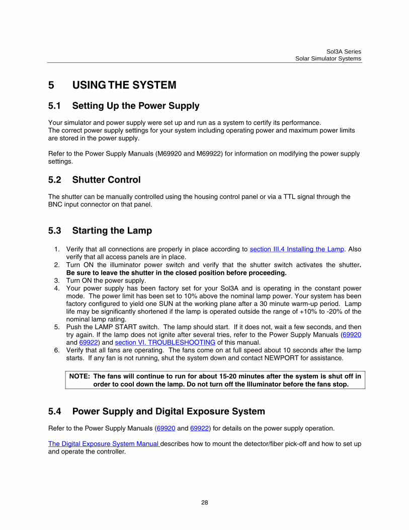
3. Turn OFF and UNPLUG the illuminator.
Photo 20: The Illuminator (rear view)
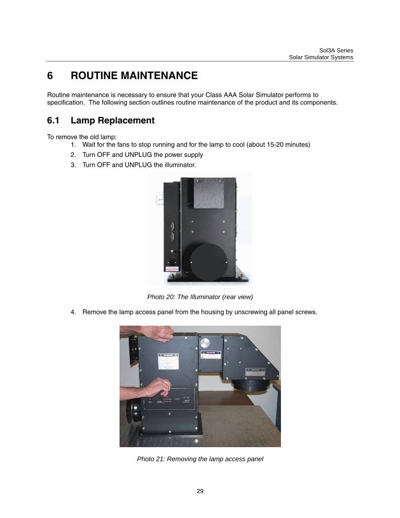
4. Remove the lamp access panel from the housing by unscrewing all panel screws.
Photo 21: Removing the lamp access panel
Sol3A Series Solar Simulator Systems
30
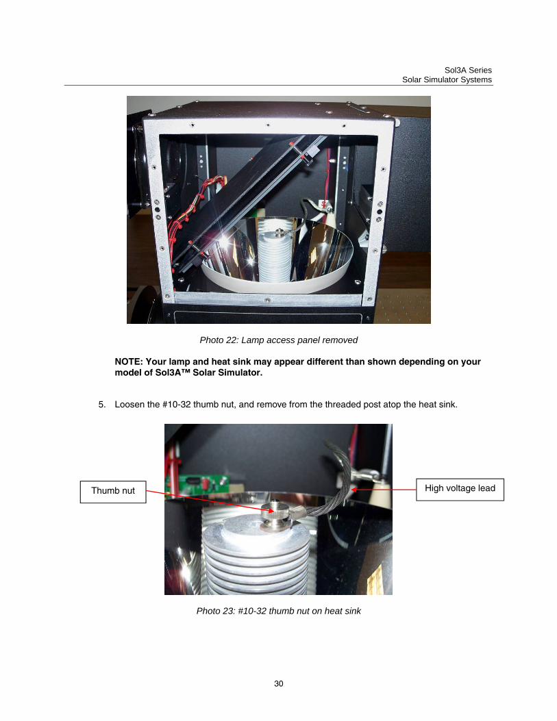
Photo 22: Lamp access panel removed
NOTE: Your lamp and heat sink may appear different than shown depending on your model of Sol3A™ Solar Simulator.
5. Loosen the #10-32 thumb nut, and remove from the threaded post atop the heat sink.
Photo 23: #10-32 thumb nut on heat sink
High voltage lead Thumb nut
Sol3A Series Solar Simulator Systems
31
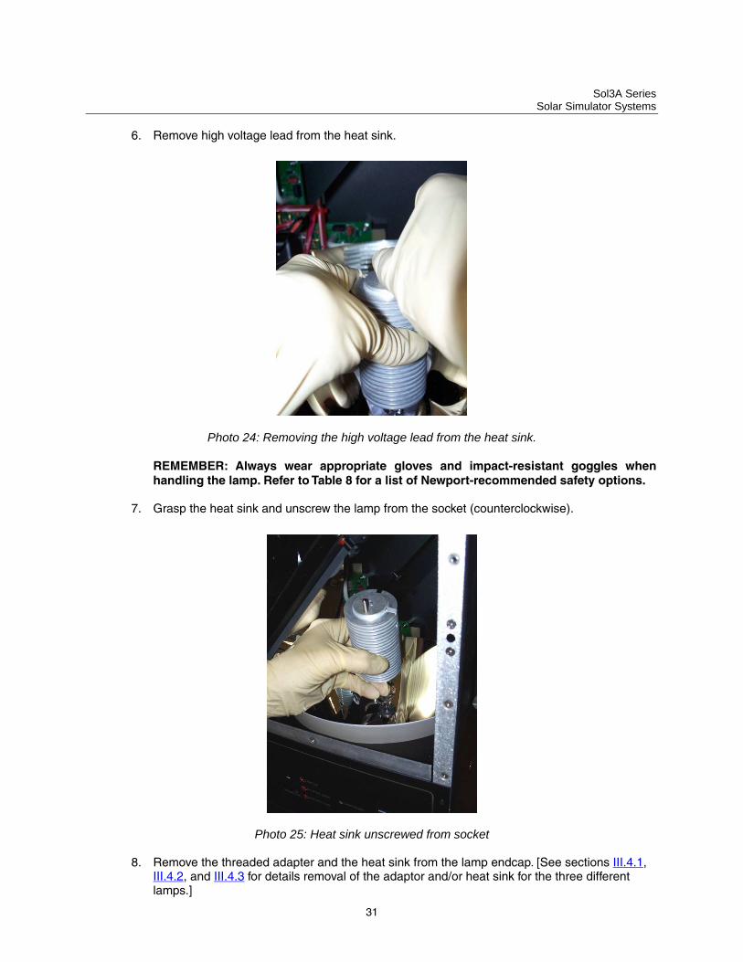
6. Remove high voltage lead from the heat sink.
Photo 24: Removing the high voltage lead from the heat sink.
REMEMBER: Always wear appropriate gloves and impact-resistant goggles when handling the lamp. Refer to Table 8 for a list of Newport-recommended safety options.
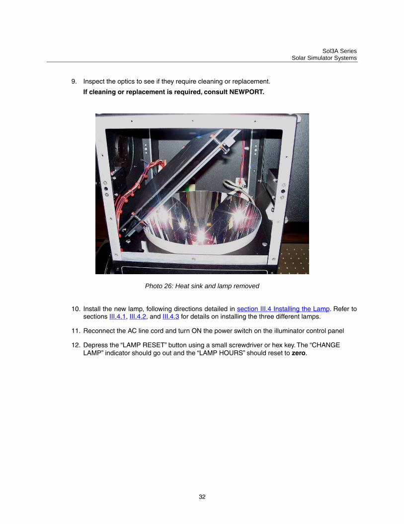
7. Grasp the heat sink and unscrew the lamp from the socket (counterclockwise).
Photo 25: Heat sink unscrewed from socket
8. Remove the threaded adapter and the heat sink from the lamp endcap. [See sections III.4.1, III.4.2, and III.4.3 for details removal of the adaptor and/or heat sink for the three different lamps.]
Sol3A Series Solar Simulator Systems
32
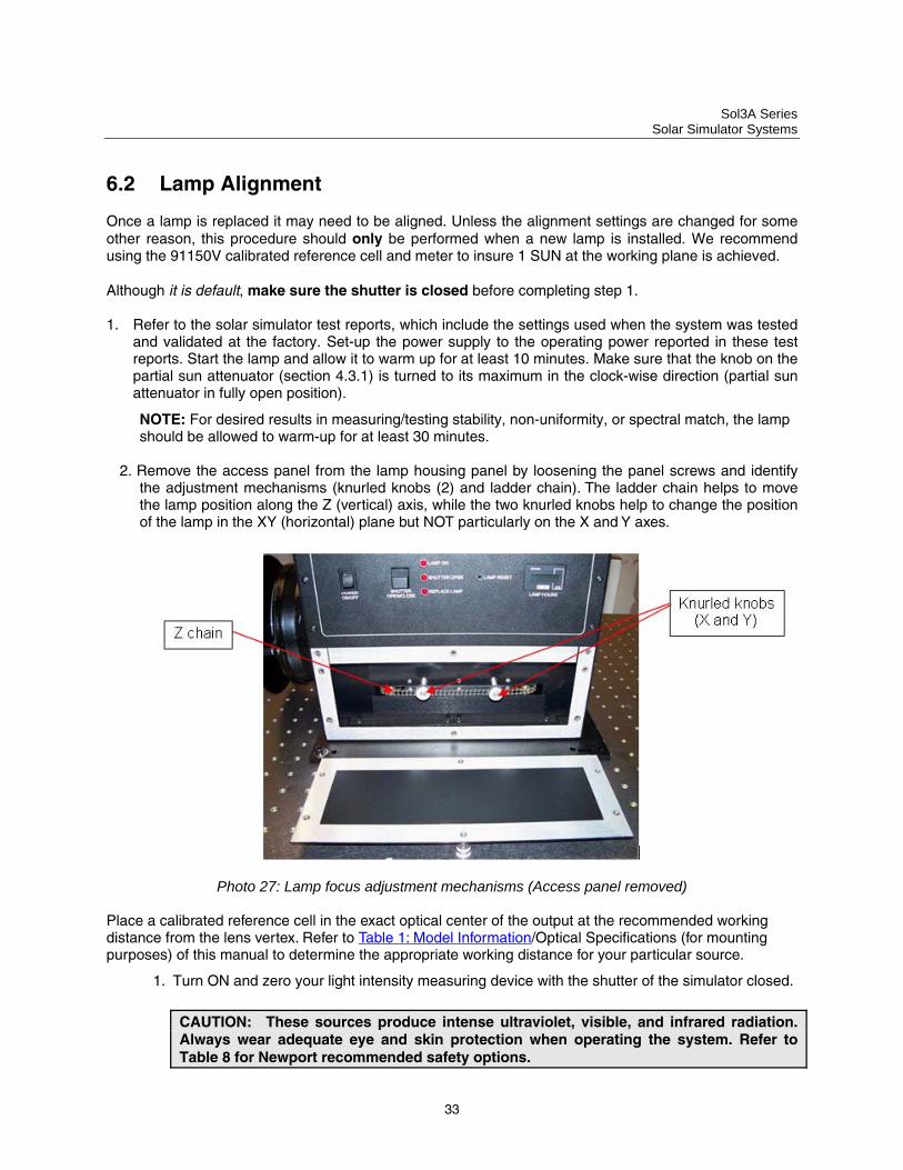
9. Inspect the optics to see if they require cleaning or replacement.
If cleaning or replacement is required, consult NEWPORT.
Photo 26: Heat sink and lamp removed
10. Install the new lamp, following directions detailed in section III.4 Installing the Lamp. Refer to sections III.4.1, III.4.2, and III.4.3 for details on installing the three different lamps.
11. Reconnect the AC line cord and turn ON the power switch on the illuminator control panel
12. Depress the “LAMP RESET” button using a small screwdriver or hex key. The “CHANGE LAMP” indicator should go out and the “LAMP HOURS” should reset to zero.
Sol3A Series Solar Simulator Systems
33
6.2 Lamp Alignment Once a lamp is replaced it may need to be aligned. Unless the alignment settings are changed for some other reason, this procedure should only be performed when a new lamp is installed. We recommend using the 91150V calibrated reference cell and meter to insure 1 SUN at the working plane is achieved.
Although it is default, make sure the shutter is closed before completing step 1. 1. Refer to the solar simulator test reports, which include the settings used when the system was tested
and validated at the factory. Set-up the power supply to the operating power reported in these test reports. Start the lamp and allow it to warm up for at least 10 minutes. Make sure that the knob on the partial sun attenuator (section 4.3.1) is turned to its maximum in the clock-wise direction (partial sun attenuator in fully open position).
NOTE: For desired results in measuring/testing stability, non-uniformity, or spectral match, the lamp should be allowed to warm-up for at least 30 minutes.
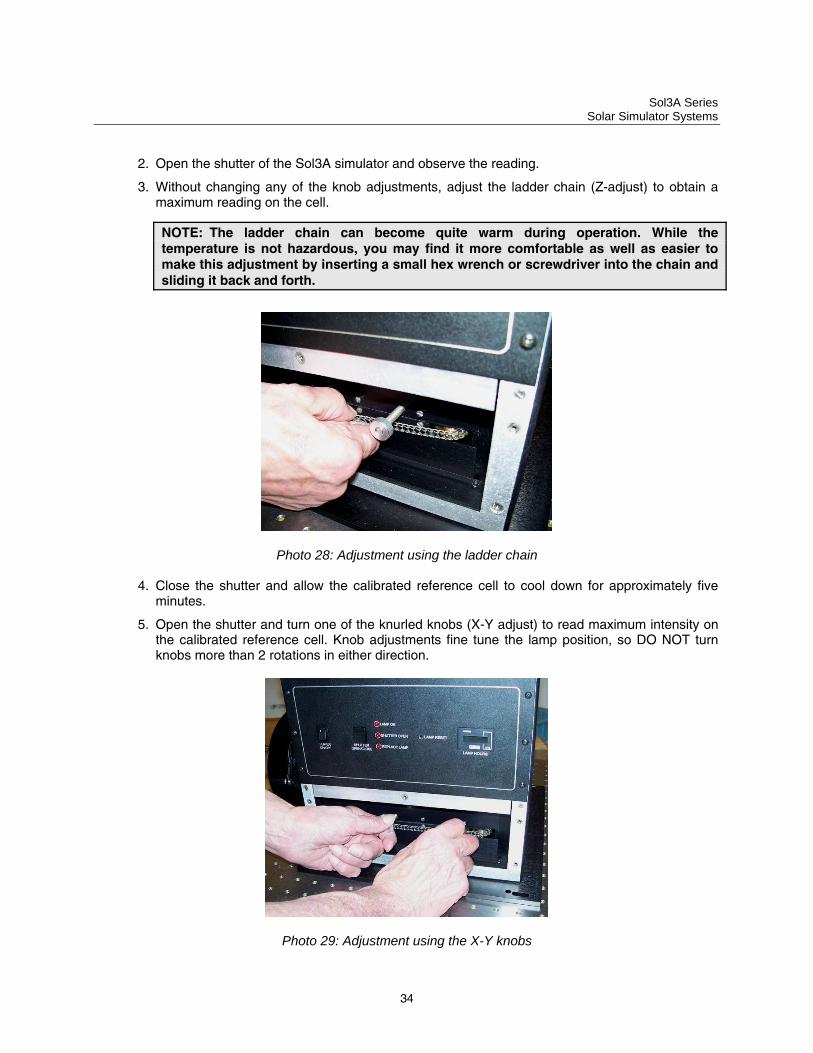
2. Remove the access panel from the lamp housing panel by loosening the panel screws and identify
the adjustment mechanisms (knurled knobs (2) and ladder chain). The ladder chain helps to move the lamp position along the Z (vertical) axis, while the two knurled knobs help to change the position of the lamp in the XY (horizontal) plane but NOT particularly on the X and Y axes.
Photo 27: Lamp focus adjustment mechanisms (Access panel removed) Place a calibrated reference cell in the exact optical center of the output at the recommended working distance from the lens vertex. Refer to Table 1: Model Information/Optical Specifications (for mounting purposes) of this manual to determine the appropriate working distance for your particular source.
1. Turn ON and zero your light intensity measuring device with the shutter of the simulator closed.
CAUTION: These sources produce intense ultraviolet, visible, and infrared radiation. Always wear adequate eye and skin protection when operating the system. Refer to Table 8 for Newport recommended safety options.
Sol3A Series Solar Simulator Systems
34
2. Open the shutter of the Sol3A simulator and observe the reading.
3. Without changing any of the knob adjustments, adjust the ladder chain (Z-adjust) to obtain a maximum reading on the cell.
NOTE: The ladder chain can become quite warm during operation. While the temperature is not hazardous, you may find it more comfortable as well as easier to make this adjustment by inserting a small hex wrench or screwdriver into the chain and sliding it back and forth.
Photo 28: Adjustment using the ladder chain
4. Close the shutter and allow the calibrated reference cell to cool down for approximately five minutes.
5. Open the shutter and turn one of the knurled knobs (X-Y adjust) to read maximum intensity on the calibrated reference cell. Knob adjustments fine tune the lamp position, so DO NOT turn knobs more than 2 rotations in either direction.
Photo 29: Adjustment using the X-Y knobs
Sol3A Series Solar Simulator Systems
35
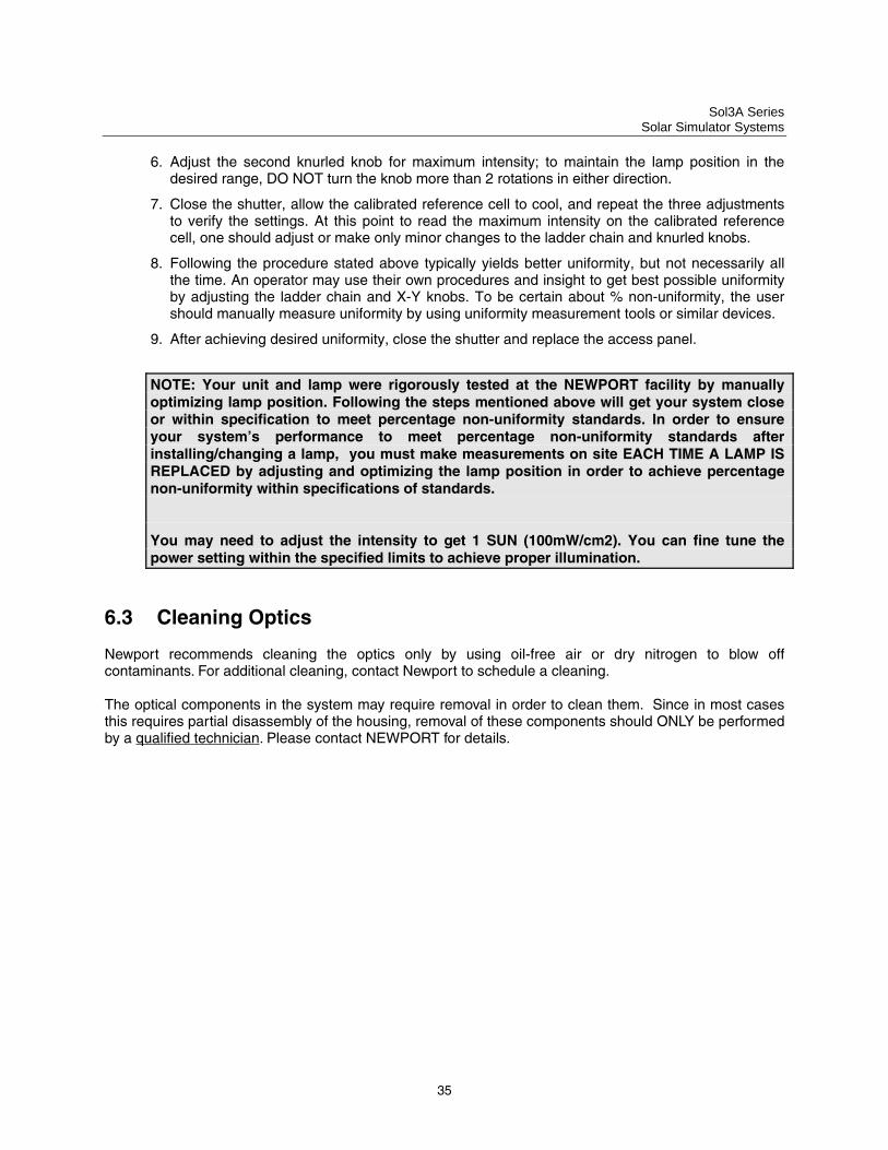
6. Adjust the second knurled knob for maximum intensity; to maintain the lamp position in the desired range, DO NOT turn the knob more than 2 rotations in either direction.
7. Close the shutter, allow the calibrated reference cell to cool, and repeat the three adjustments to verify the settings. At this point to read the maximum intensity on the calibrated reference cell, one should adjust or make only minor changes to the ladder chain and knurled knobs.
8. Following the procedure stated above typically yields better uniformity, but not necessarily all the time. An operator may use their own procedures and insight to get best possible uniformity by adjusting the ladder chain and X-Y knobs. To be certain about % non-uniformity, the user should manually measure uniformity by using uniformity measurement tools or similar devices.
9. After achieving desired uniformity, close the shutter and replace the access panel.
NOTE: Your unit and lamp were rigorously tested at the NEWPORT facility by manually optimizing lamp position. Following the steps mentioned above will get your system close or within specification to meet percentage non-uniformity standards. In order to ensure your system’s performance to meet percentage non-uniformity standards after installing/changing a lamp, you must make measurements on site EACH TIME A LAMP IS REPLACED by adjusting and optimizing the lamp position in order to achieve percentage non-uniformity within specifications of standards.
You may need to adjust the intensity to get 1 SUN (100mW/cm2). You can fine tune the power setting within the specified limits to achieve proper illumination.
6.3 Cleaning Optics Newport recommends cleaning the optics only by using oil-free air or dry nitrogen to blow off contaminants. For additional cleaning, contact Newport to schedule a cleaning. The optical components in the system may require removal in order to clean them. Since in most cases this requires partial disassembly of the housing, removal of these components should ONLY be performed by a qualified technician. Please contact NEWPORT for details.
Sol3A Series Solar Simulator Systems
36
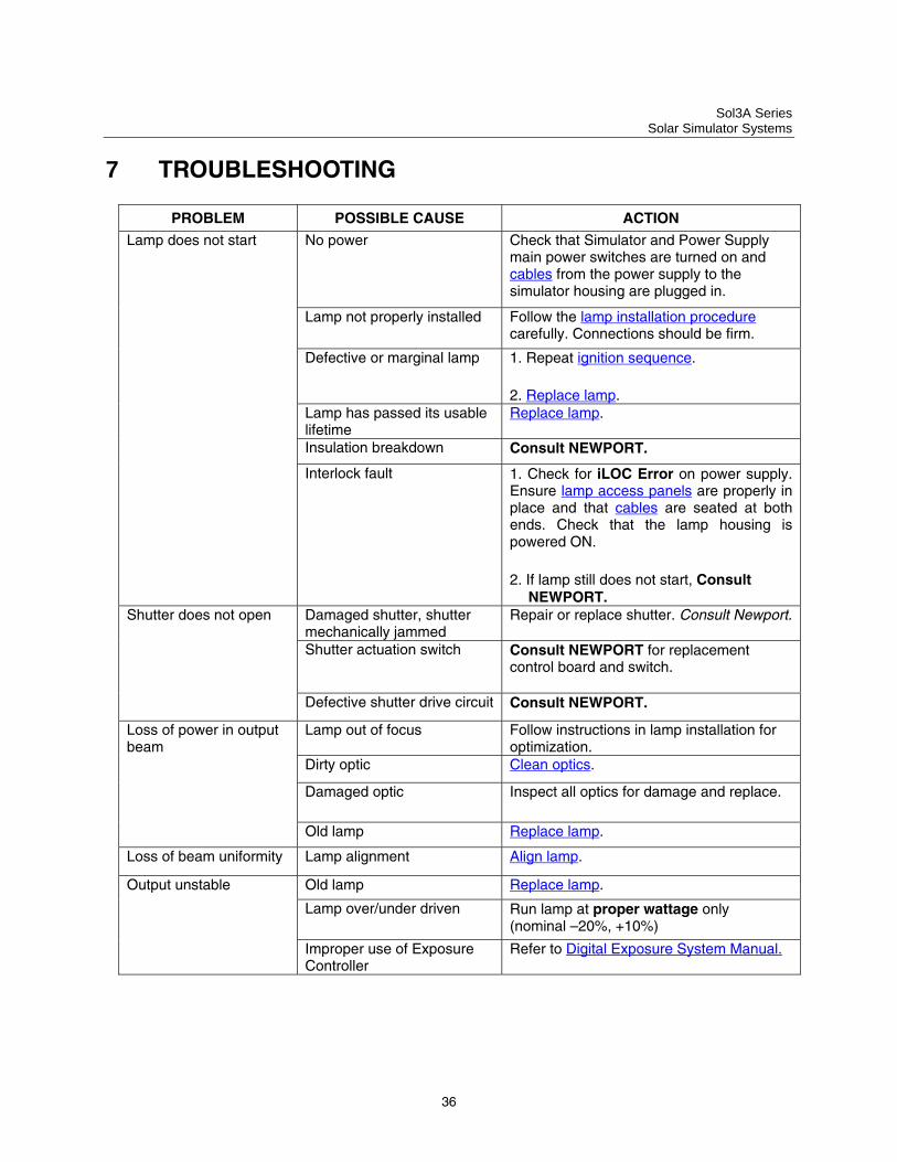
7 TROUBLESHOOTING
PROBLEM POSSIBLE CAUSE ACTION
Lamp does not start No power Check that Simulator and Power Supply main power switches are turned on and cables from the power supply to the simulator housing are plugged in.
Lamp not properly installed Follow the lamp installation procedure carefully. Connections should be firm.
Defective or marginal lamp 1. Repeat ignition sequence.
2. Replace lamp. Lamp has passed its usable lifetime
Replace lamp.
Insulation breakdown Consult NEWPORT.
Interlock fault 1. Check for iLOC Error on power supply. Ensure lamp access panels are properly in place and that cables are seated at both ends. Check that the lamp housing is powered ON.
2. If lamp still does not start, Consult NEWPORT.
Shutter does not open
Damaged shutter, shutter mechanically jammed
Repair or replace shutter. Consult Newport.
Shutter actuation switch Consult NEWPORT for replacement control board and switch.
Defective shutter drive circuit Consult NEWPORT.
Loss of power in output beam
Lamp out of focus Follow instructions in lamp installation for optimization.
Dirty optic Clean optics.
Damaged optic Inspect all optics for damage and replace.
Old lamp Replace lamp.
Loss of beam uniformity Lamp alignment Align lamp.
Output unstable Old lamp Replace lamp.
Lamp over/under driven Run lamp at proper wattage only (nominal –20%, +10%)
Improper use of Exposure Controller
Refer to Digital Exposure System Manual.
Sol3A Series Solar Simulator Systems
37
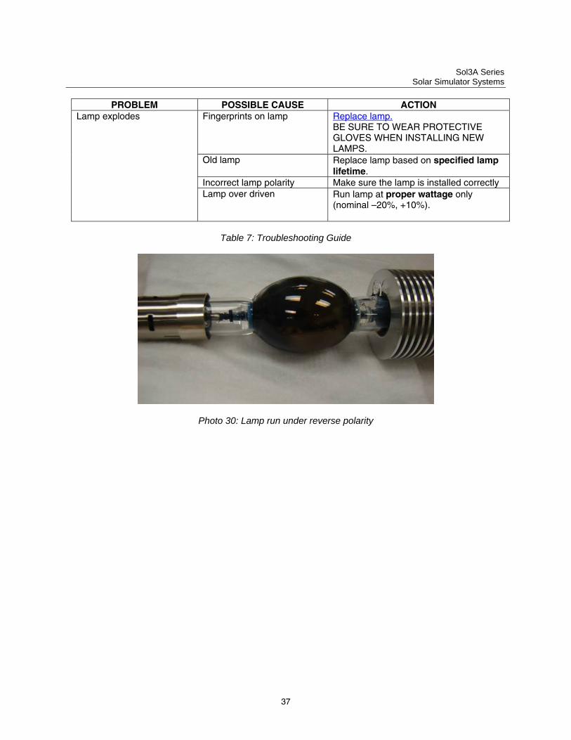
PROBLEM POSSIBLE CAUSE ACTION Lamp explodes Fingerprints on lamp
Replace lamp. BE SURE TO WEAR PROTECTIVE GLOVES WHEN INSTALLING NEW LAMPS.
Old lamp Replace lamp based on specified lamp lifetime.
Incorrect lamp polarity Make sure the lamp is installed correctly
Lamp over driven
Run lamp at proper wattage only (nominal –20%, +10%).
Table 7: Troubleshooting Guide
Photo 30: Lamp run under reverse polarity
Sol3A Series Solar Simulator Systems
38
8 WARRANTY AND RETURNS
8.1 Contacting Oriel Instruments Oriel Instruments belongs to Newport Corporation's family of brands. Thanks to a steadfast commitment to quality, innovation, hard work and customer care, Newport is trusted the world over as the complete source for all photonics and laser technology and equipment. Founded in 1969, Newport is a pioneering single-source solutions provider of laser and photonics components to the leaders in scientific research, life and health sciences, photovoltaics, microelectronics, industrial manufacturing and homeland security markets. Newport Corporation proudly serves customers across Canada, Europe, Asia and the United States through 9 international subsidiaries and 24 sales offices worldwide. Every year, the Newport Resource catalog is hailed as the premier sourcebook for those in need of advanced technology products and services. It is available by mail request or through Newport's website. The website is where one will find product updates, interactive demonstrations, specification charts and more. To obtain information regarding sales, technical support, or factory service, United States and Canadian customers should contact Oriel Instruments directly.
Oriel Instruments 31950 E. Frontage Rd.
Bozeman, MT 59715 USA Telephone: 877-835-9620 (toll-free in United States) 949-863-3144 Fax: 949-253-1680 Sales: [email protected] Technical assistance & Repair Service: [email protected] Customers outside of the United States must contact their regional representative for all sales, technical support and service inquiries. A list of worldwide representatives can be found on Newport’s website.
Sol3A Series Solar Simulator Systems
39
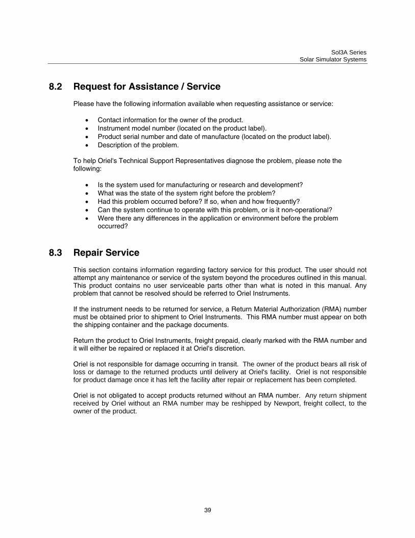
8.2 Request for Assistance / Service
Please have the following information available when requesting assistance or service:
Contact information for the owner of the product. Instrument model number (located on the product label). Product serial number and date of manufacture (located on the product label). Description of the problem.
To help Oriel's Technical Support Representatives diagnose the problem, please note the following:
Is the system used for manufacturing or research and development? What was the state of the system right before the problem? Had this problem occurred before? If so, when and how frequently? Can the system continue to operate with this problem, or is it non-operational? Were there any differences in the application or environment before the problem
occurred?
8.3 Repair Service
This section contains information regarding factory service for this product. The user should not attempt any maintenance or service of the system beyond the procedures outlined in this manual. This product contains no user serviceable parts other than what is noted in this manual. Any problem that cannot be resolved should be referred to Oriel Instruments. If the instrument needs to be returned for service, a Return Material Authorization (RMA) number must be obtained prior to shipment to Oriel Instruments. This RMA number must appear on both the shipping container and the package documents. Return the product to Oriel Instruments, freight prepaid, clearly marked with the RMA number and it will either be repaired or replaced it at Oriel's discretion. Oriel is not responsible for damage occurring in transit. The owner of the product bears all risk of loss or damage to the returned products until delivery at Oriel's facility. Oriel is not responsible for product damage once it has left the facility after repair or replacement has been completed. Oriel is not obligated to accept products returned without an RMA number. Any return shipment received by Oriel without an RMA number may be reshipped by Newport, freight collect, to the owner of the product.
Sol3A Series Solar Simulator Systems
40
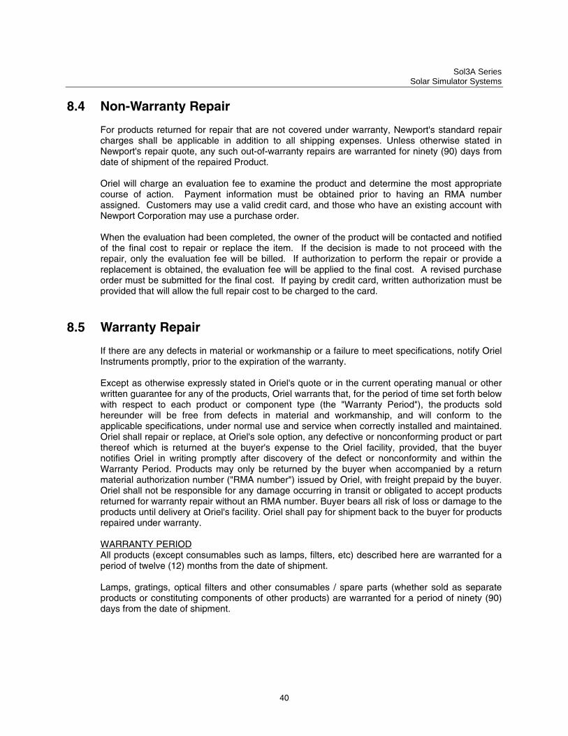
8.4 Non-Warranty Repair
For products returned for repair that are not covered under warranty, Newport's standard repair charges shall be applicable in addition to all shipping expenses. Unless otherwise stated in Newport's repair quote, any such out-of-warranty repairs are warranted for ninety (90) days from date of shipment of the repaired Product. Oriel will charge an evaluation fee to examine the product and determine the most appropriate course of action. Payment information must be obtained prior to having an RMA number assigned. Customers may use a valid credit card, and those who have an existing account with Newport Corporation may use a purchase order. When the evaluation had been completed, the owner of the product will be contacted and notified of the final cost to repair or replace the item. If the decision is made to not proceed with the repair, only the evaluation fee will be billed. If authorization to perform the repair or provide a replacement is obtained, the evaluation fee will be applied to the final cost. A revised purchase order must be submitted for the final cost. If paying by credit card, written authorization must be provided that will allow the full repair cost to be charged to the card.
8.5 Warranty Repair
If there are any defects in material or workmanship or a failure to meet specifications, notify Oriel Instruments promptly, prior to the expiration of the warranty. Except as otherwise expressly stated in Oriel's quote or in the current operating manual or other written guarantee for any of the products, Oriel warrants that, for the period of time set forth below with respect to each product or component type (the "Warranty Period"), the products sold hereunder will be free from defects in material and workmanship, and will conform to the applicable specifications, under normal use and service when correctly installed and maintained. Oriel shall repair or replace, at Oriel's sole option, any defective or nonconforming product or part thereof which is returned at the buyer's expense to the Oriel facility, provided, that the buyer notifies Oriel in writing promptly after discovery of the defect or nonconformity and within the Warranty Period. Products may only be returned by the buyer when accompanied by a return material authorization number ("RMA number") issued by Oriel, with freight prepaid by the buyer. Oriel shall not be responsible for any damage occurring in transit or obligated to accept products returned for warranty repair without an RMA number. Buyer bears all risk of loss or damage to the products until delivery at Oriel's facility. Oriel shall pay for shipment back to the buyer for products repaired under warranty. WARRANTY PERIOD All products (except consumables such as lamps, filters, etc) described here are warranted for a period of twelve (12) months from the date of shipment. Lamps, gratings, optical filters and other consumables / spare parts (whether sold as separate products or constituting components of other products) are warranted for a period of ninety (90) days from the date of shipment.
Sol3A Series Solar Simulator Systems
41
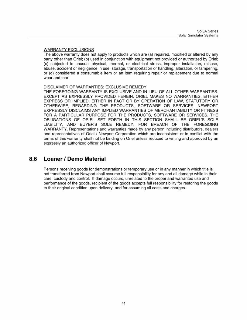
WARRANTY EXCLUSIONS The above warranty does not apply to products which are (a) repaired, modified or altered by any party other than Oriel; (b) used in conjunction with equipment not provided or authorized by Oriel; (c) subjected to unusual physical, thermal, or electrical stress, improper installation, misuse, abuse, accident or negligence in use, storage, transportation or handling, alteration, or tampering, or (d) considered a consumable item or an item requiring repair or replacement due to normal wear and tear. DISCLAIMER OF WARRANTIES; EXCLUSIVE REMEDY THE FOREGOING WARRANTY IS EXCLUSIVE AND IN LIEU OF ALL OTHER WARRANTIES. EXCEPT AS EXPRESSLY PROVIDED HEREIN, ORIEL MAKES NO WARRANTIES, EITHER EXPRESS OR IMPLIED, EITHER IN FACT OR BY OPERATION OF LAW, STATUTORY OR OTHERWISE, REGARDING THE PRODUCTS, SOFTWARE OR SERVICES. NEWPORT EXPRESSLY DISCLAIMS ANY IMPLIED WARRANTIES OF MERCHANTABILITY OR FITNESS FOR A PARTICULAR PURPOSE FOR THE PRODUCTS, SOFTWARE OR SERVICES. THE OBLIGATIONS OF ORIEL SET FORTH IN THIS SECTION SHALL BE ORIEL'S SOLE LIABILITY, AND BUYER'S SOLE REMEDY, FOR BREACH OF THE FOREGOING WARRANTY. Representations and warranties made by any person including distributors, dealers and representatives of Oriel / Newport Corporation which are inconsistent or in conflict with the terms of this warranty shall not be binding on Oriel unless reduced to writing and approved by an expressly an authorized officer of Newport.
8.6 Loaner / Demo Material
Persons receiving goods for demonstrations or temporary use or in any manner in which title is not transferred from Newport shall assume full responsibility for any and all damage while in their care, custody and control. If damage occurs, unrelated to the proper and warranted use and performance of the goods, recipient of the goods accepts full responsibility for restoring the goods to their original condition upon delivery, and for assuming all costs and charges.
Sol3A Series Solar Simulator Systems
42
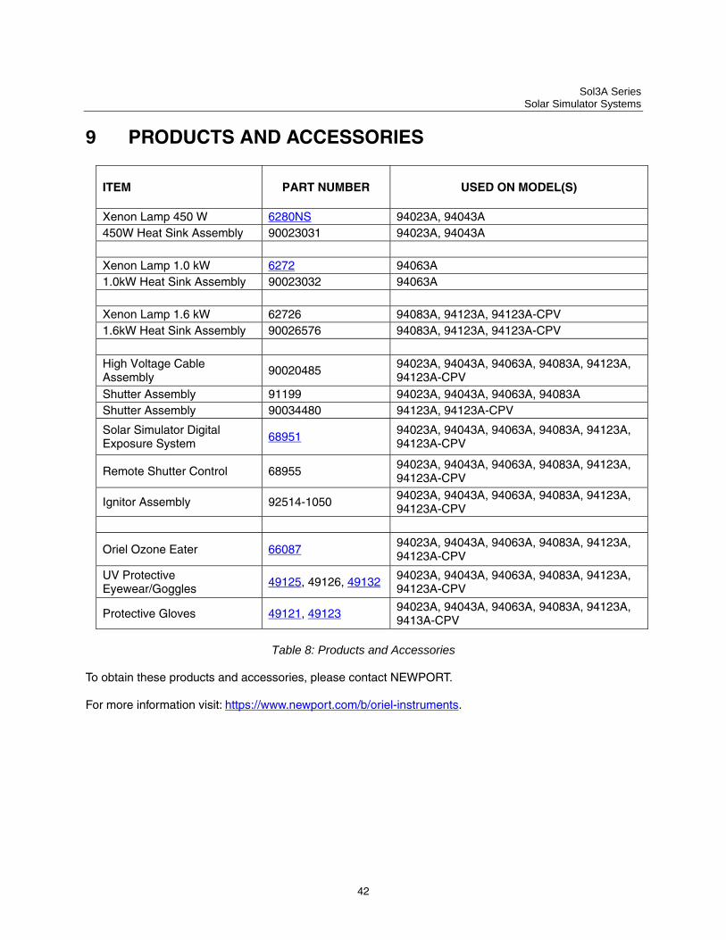
9 PRODUCTS AND ACCESSORIES
ITEM
PART NUMBER
USED ON MODEL(S)
Xenon Lamp 450 W 6280NS 94023A, 94043A 450W Heat Sink Assembly 90023031 94023A, 94043A Xenon Lamp 1.0 kW 6272 94063A 1.0kW Heat Sink Assembly 90023032 94063A Xenon Lamp 1.6 kW 62726 94083A, 94123A, 94123A-CPV 1.6kW Heat Sink Assembly 90026576 94083A, 94123A, 94123A-CPV High Voltage Cable Assembly 90020485
94023A, 94043A, 94063A, 94083A, 94123A, 94123A-CPV
Shutter Assembly 91199 94023A, 94043A, 94063A, 94083A Shutter Assembly 90034480 94123A, 94123A-CPV
Solar Simulator Digital Exposure System 68951
94023A, 94043A, 94063A, 94083A, 94123A, 94123A-CPV
Remote Shutter Control 68955 94023A, 94043A, 94063A, 94083A, 94123A, 94123A-CPV
Ignitor Assembly 92514-1050 94023A, 94043A, 94063A, 94083A, 94123A, 94123A-CPV
Oriel Ozone Eater 66087 94023A, 94043A, 94063A, 94083A, 94123A, 94123A-CPV
UV Protective Eyewear/Goggles 49125, 49126, 49132 94023A, 94043A, 94063A, 94083A, 94123A,
94123A-CPV
Protective Gloves 49121, 49123 94023A, 94043A, 94063A, 94083A, 94123A, 9413A-CPV
Table 8: Products and Accessories
To obtain these products and accessories, please contact NEWPORT. For more information visit: https://www.newport.com/b/oriel-instruments.
Sol3A Series Solar Simulator Systems
43
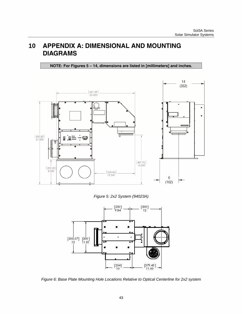
10 APPENDIX A: DIMENSIONAL AND MOUNTING DIAGRAMS
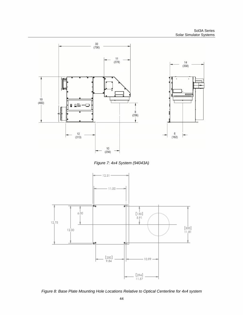
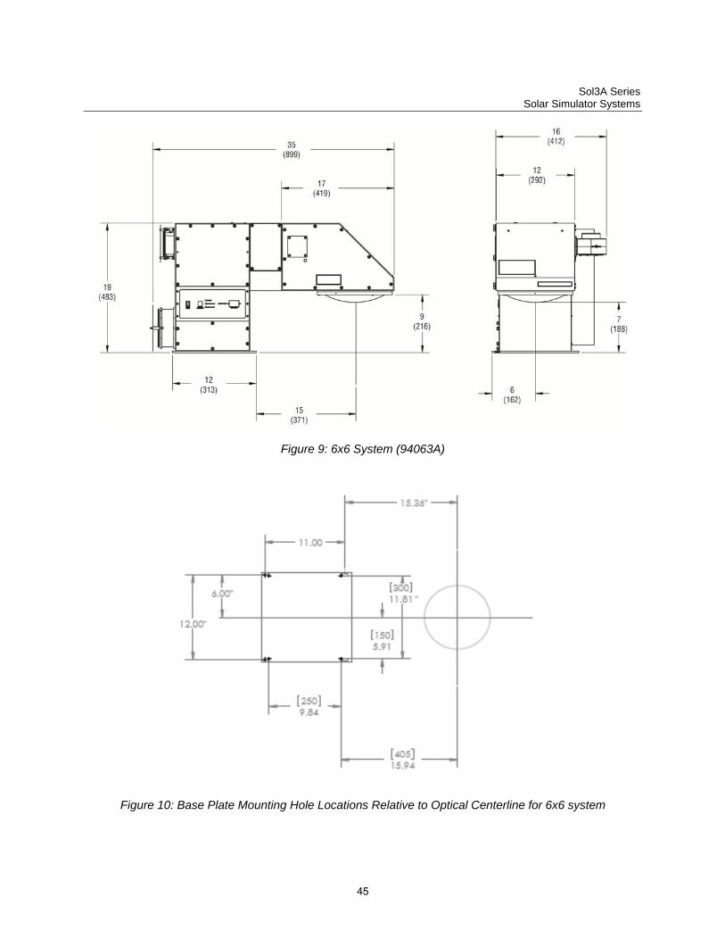
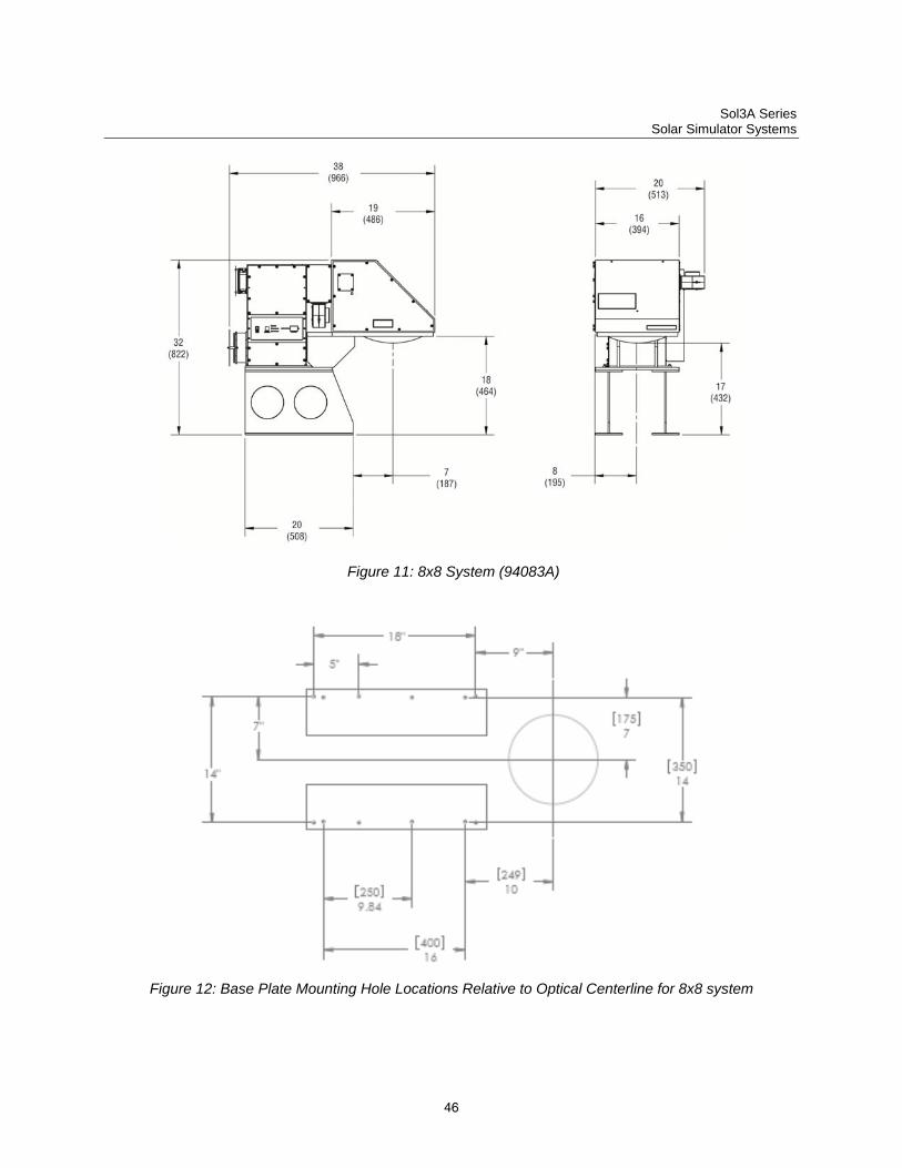
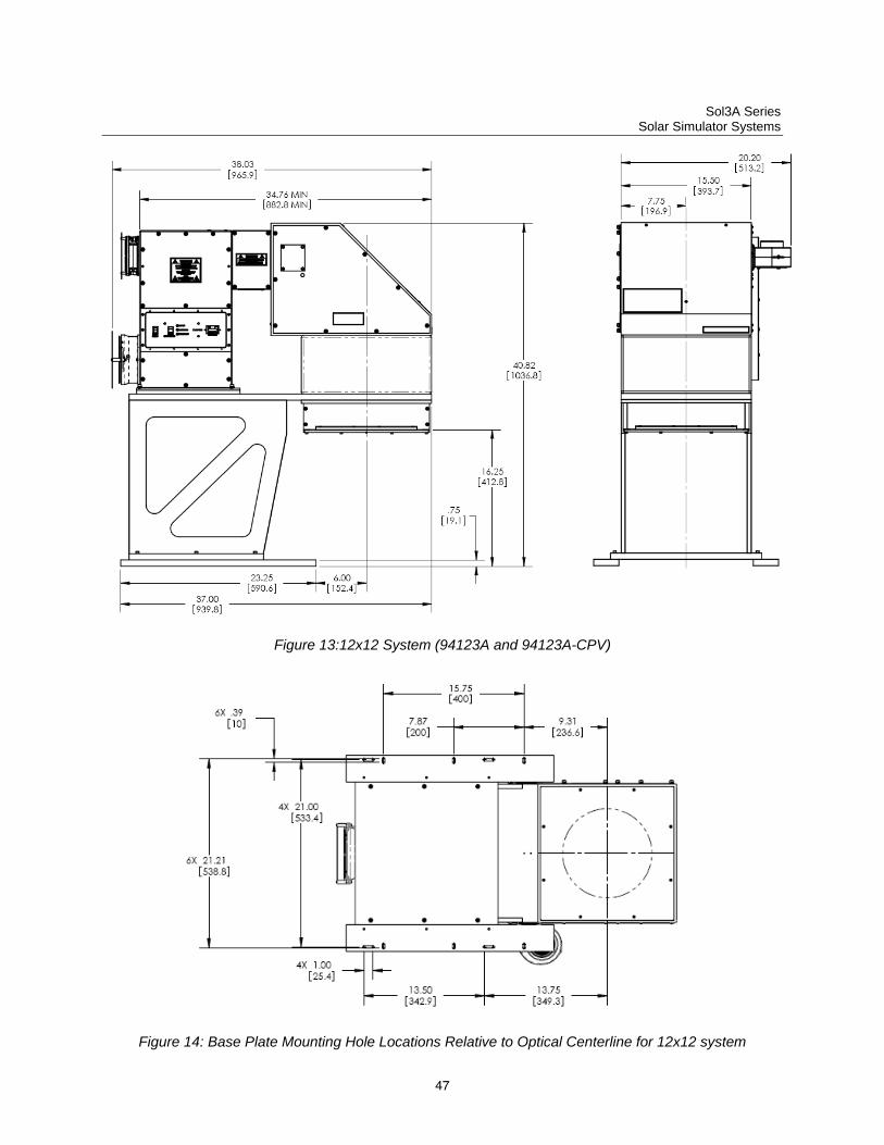
NOTE: For Figures 5 – 14, dimensions are listed in [millimeters] and inches.
Figure 5: 2x2 System (94023A)
Figure 6: Base Plate Mounting Hole Locations Relative to Optical Centerline for 2x2 system
Sol3A Series Solar Simulator Systems
44
Figure 7: 4x4 System (94043A)
Figure 8: Base Plate Mounting Hole Locations Relative to Optical Centerline for 4x4 system
Sol3A Series Solar Simulator Systems
45
Figure 9: 6x6 System (94063A)
Figure 10: Base Plate Mounting Hole Locations Relative to Optical Centerline for 6x6 system
Sol3A Series Solar Simulator Systems
46
Figure 11: 8x8 System (94083A)
Figure 12: Base Plate Mounting Hole Locations Relative to Optical Centerline for 8x8 system
Sol3A Series Solar Simulator Systems
47
Figure 13:12x12 System (94123A and 94123A-CPV)
Figure 14: Base Plate Mounting Hole Locations Relative to Optical Centerline for 12x12 system
Sol3A Series Solar Simulator Systems
48
11 APPENDIX B: REPORTS AND CERTIFICATIONS
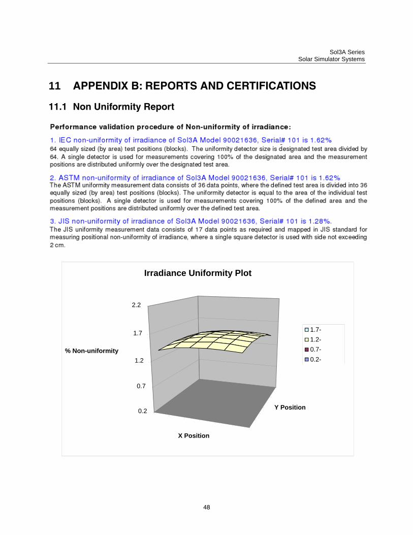
11.1 Non Uniformity Report
0.2
0.7
1.2
1.7
2.2
% Non-uniformity
X Position
Y Position
Irradiance Uniformity Plot
1.7-
1.2-
0.7-
0.2-
Sol3A Series Solar Simulator Systems
49
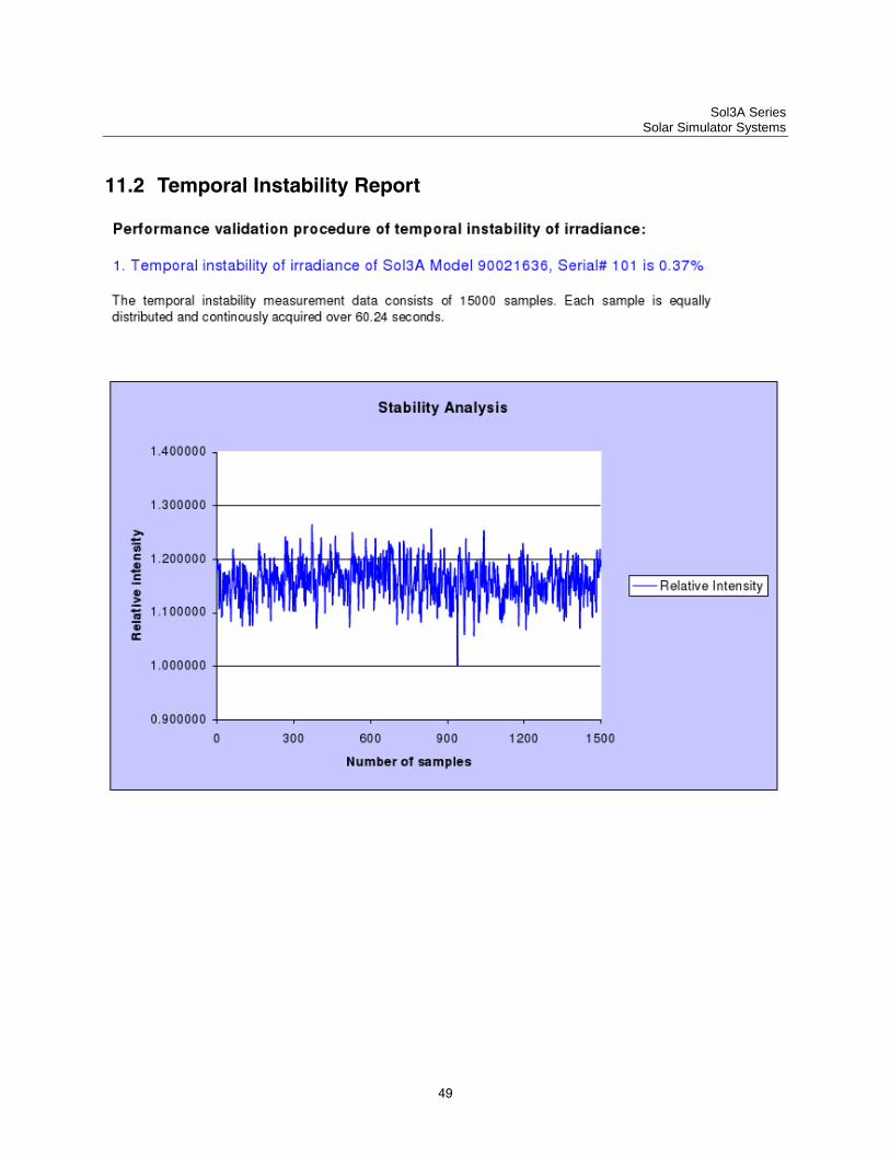
11.2 Temporal Instability Report
Sol3A Series Solar Simulator Systems
50
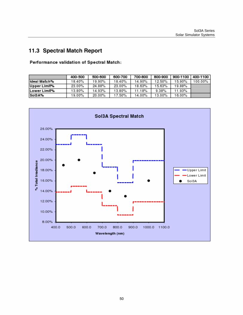
11.3 Spectral Match Report

First printing 2010
© 2011 by Newport Corporation, Irvine, CA. All rights reserved. No part of this manual may be reproduced or copied without the prior written approval of Newport Corporation.
This manual has been provided for information only and product specifications are subject to change without notice. Any change will be reflected in future printings. Newport Corporation 1791 Deere Avenue Irvine, CA, 92606 USA