Embed Size (px)
Citation preview

Solar Energy Management System
SEMS
Est.1968
2

3
IntroductionThycon is Australia’s leading manufacturer of electronics equipment for power management applications. Renowned for its highly reliable uninterruptible power supplies (UPS), Thycon increasingly serves the equally demanding inverter needs of the renewable energy sector, most notably, that of the solar power industry, with its dedicated range of power inverters for solar farms.
Climate change and shrinking fossil resources require innovative concepts for future energy supplies. Thycon considers decentralized and modular energy technology as fundamental to an environmentally friendly and sustainable energy supply, in Australia and overseas.
As a pioneer in photovoltaic, Thycon aims to provide institutional owners of solar power plants with optimal yields and seamless supply to the public grid with maximized profitability thanks to its low-loss solar inverter, maximal power-point tracking and peak power support (peak power booster).
A key component for feeding the solar power generated by the solar panel system to the public grid, is the inverter. This sophisticated equipment transforms the generated DC-power into grid-compatible AC-power, according to severe standards and safety regulations.
One of the key challenges of the inverter is to assure that the solar cell’s output is transferred with the highest possible efficiency and yield. Even improvements in the range of tenths of a percent lead to appreciable increases in the customers’ profits since solar plants are an investment for at least 20 years. To enable this, Thycon guarantees the long-term reliability it has long provided with the company’s range of UPS systems. Solar-farm profitability depends on efficiency, low life-cycle costs high harvest yields and availability, not only of sunshine but of power in its absence which can be achieved thanks to Thycon energy-storage and power regulation systems.

4
Solar FarmsSolar-farms consist generally of multiple photovoltaic panels (PVPs) distributed over a large area and oriented towards the sun. The orientation is either in a fixed position determined by best average energy yield or variable and able to track the sun for optimal yield.
In either case, the panels are widely distributed, necessarily in differing positions and of slightly differing characteristics due to manufacturing tolerances, aging and dirt cover. These differences result in different outputs from each panel which is why panels cannot all be series and parallel connected with impunity without incurring a yield loss (reduced energy harvest).
The most common approach to PV panel interconnection is to convert the PVP’s DC output to 50Hz AC and connect the AC outputs to a common AC bus system which ultimately connects to the grid.
The logic behind this approach is that the outputs will have to be converted to AC anyway and since some form of conversion is needed at each panel, it might as well be done directly at the PVP output allowing standard LV AC switchgear throughout the solar-farm.
The Thycon SEMSThe problem with the standard approach to solar-farm energy management, is that although the inverter, which turns DC to AC, can be designed to maximize the power output of each panel, the farm as a whole is interconnected by a low voltage (LV) 3-phase power network channelling hundreds of kilowatts over hundreds or thousands of meters. This inevitably leads to resistive losses and unnecessary reactive power flow within the farm, which further increases losses.
A more efficient approach is to keep the output of each panel in DC form but at an increased and regulated level and to channel power throughout the farm in this form until it has been collected at the PCC (point of common coupling) of the farm to the grid. At this point, a single, large, high-efficiency power inverter converts the DC to 3-phase AC and injects it into the grid.
The advantages of this system are:
• distribution within the farm is done at higher DC voltage and hence lower current, reducing cable losses while reducing cable sections and hence cabling costs
• a 2-wire distribution network is used instead of a 3-wire system, further reducing cabling costs
Wind Farm Generators
5
• DC current has an 11% lower form-factor (=IRMS/IAVE) which further reduces cable losses and/or costs
• DC power is distributed at unity power factor (PF), further reducing cable losses and obviating any need for PF correction (PFC) within the farm
• a DC distribution system lends itself easily to additional solar-farm functions such as energy storage and “peak-lopping”
• a DC distribution system allows greater design flexibility in terms of voltage level: the longer the cable runs, the higher the DC voltage can be set with minimal cost impact (AC systems require different inverter transformers)
• each panel is controlled by a chopper instead of an inverter which reduces component count by a factor three, in turn, reducing failure rates (proportional to component count)
• choppers are simpler and cheaper than inverters which reduces the capital costs
• a single large inverter is more efficient than lots of small ones and the overall investment cost is also lower: there is only one inverter controller per farm instead of per PVP
• the Thycon Solar Inverter, differs from conventional
PVP inverters in that it is a current source inverter (CSI) as opposed to a voltage source inverter (VSI): CSIs can be realised with thyristors which are highly reliable, low-loss semiconductors, well suited for high power inverter
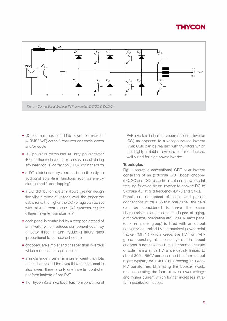
TopologiesFig. 1 shows a conventional IGBT solar inverter consisting of an (optional) IGBT boost chopper (LC, SC and DC) to control maximum power-point tracking followed by an inverter to convert DC to 3-phase AC at grid frequency (D1-6 and S1-6).Panels are composed of series and parallel connections of cells. Within one panel, the cells can be considered to have the same characteristics (and the same degree of aging, dirt coverage, orientation etc). Ideally, each panel (or small panel group) is fitted with an output converter controlled by the maximal power-point tracker (MPPT) which keeps the PVP or PVP-group operating at maximal yield. The boost chopper is not essential but is a common feature of solar farms since PVPs are usually limited to about 300 – 550V per panel and the farm output might typically be a 480V bus feeding an LV-to-MV transformer. Eliminating the booster would mean operating the farm at even lower voltage and higher current which further increases intra-farm distribution losses.
Fig. 1 - Conventional 2-stage PVP converter (DC/DC & DC/AC)
6
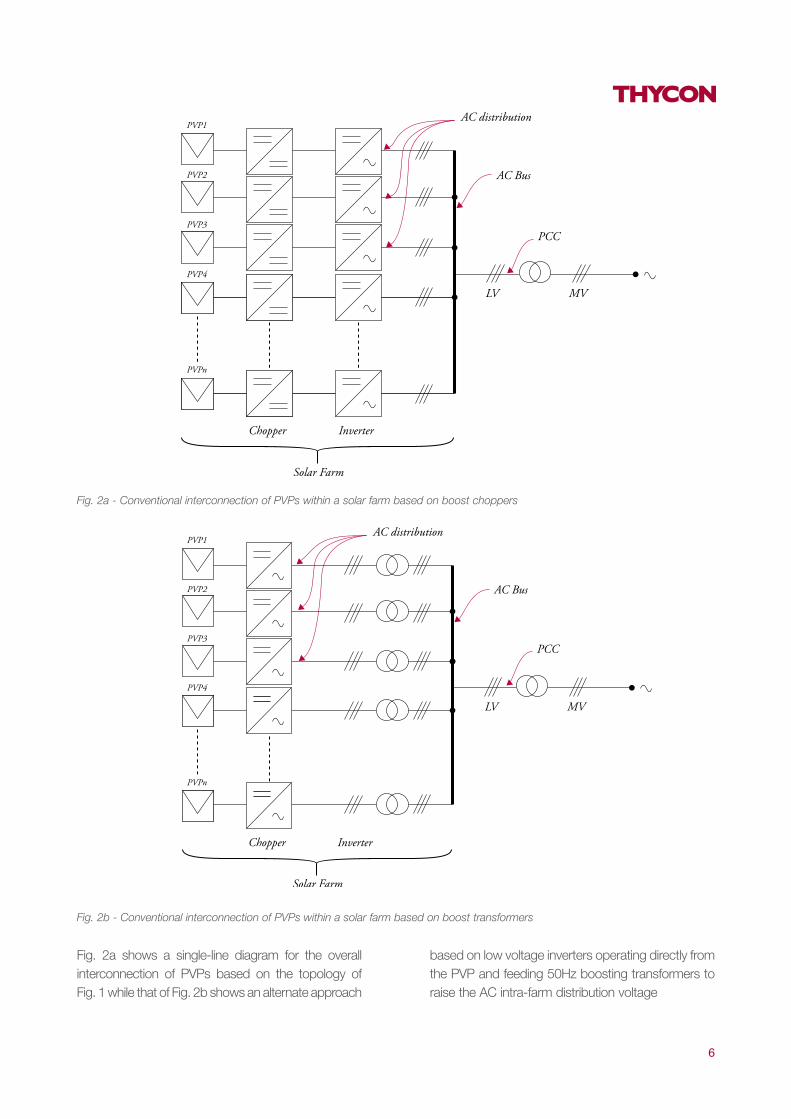
Fig. 2a shows a single-line diagram for the overall interconnection of PVPs based on the topology of Fig. 1 while that of Fig. 2b shows an alternate approach
based on low voltage inverters operating directly from the PVP and feeding 50Hz boosting transformers to raise the AC intra-farm distribution voltage
Fig. 2a - Conventional interconnection of PVPs within a solar farm based on boost choppers
Fig. 2b - Conventional interconnection of PVPs within a solar farm based on boost transformers
7
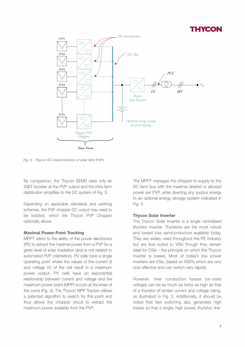
Fig. 3 - Thycon DC interconnection of solar farm PVPs
By comparison, the Thycon SEMS uses only an IGBT booster at the PVP output and the intra-farm distribution simplifies to the DC system of Fig. 3.
Depending on applicable standards and earthing schemes, the PVP chopper DC output may need to be isolated, which the Thycon PVP Chopper optionally allows.
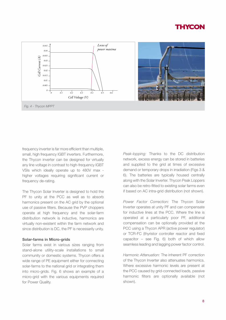
Maximal Power-Point TrackingMPPT refers to the ability of the power electronics (PE) to extract the maximal power from a PVP for a given level of solar irradiation (and is not related to automated PVP orientation). PV cells have a single operating point where the values of the current (I) and voltage (V) of the cell result in a maximum power output. PV cells have an exponential relationship between current and voltage and the maximum power point (MPP) occurs at the knee of the curve (Fig. 4). The Thycon MPP Tracker utilises a patented algorithm to search for this point and thus allows the chopper circuit to extract the maximum power available from the PVP.
The MPPT manages the chopper to supply to the DC farm bus with the maximal desired or allowed power per PVP, while diverting any surplus energy to an optional energy storage system indicated in Fig. 3.
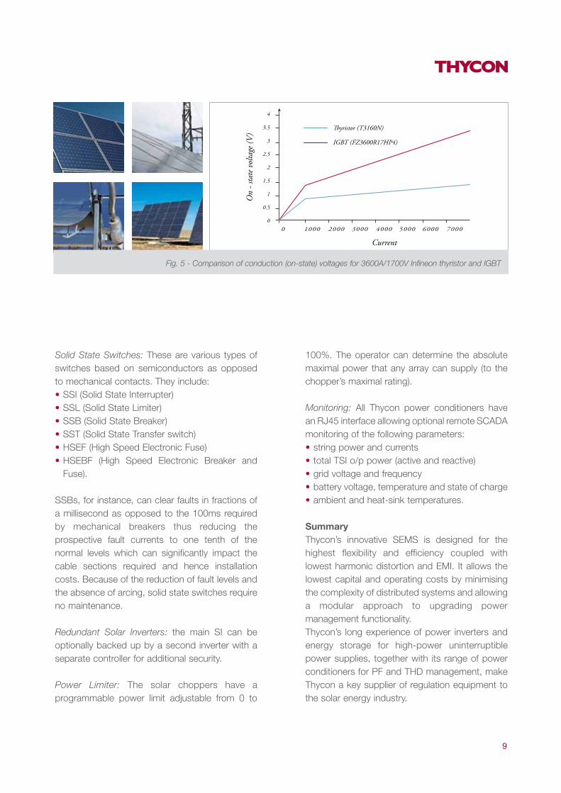
Thycon Solar InverterThe Thycon Solar Inverter is a single centralised thyristor inverter. Thyristors are the most robust and lowest loss semiconductors available today. They are widely used throughout the PE industry but are less suited to VSIs though they remain ideal for CSIs – the principle on which the Thycon inverter is based. Most of today’s low power inverters are VSIs, based on IGBTs which are very cost effective and can switch very rapidly.
However, their conduction losses (on-state voltage) can be as much as twice as high as that of a thyristor of similar current and voltage rating, as illustrated in Fig. 5. Additionally, it should be noted that fast switching also generates high losses so that a single, high power, thyristor, line-
8
frequency inverter is far more efficient than multiple, small, high frequency IGBT inverters. Furthermore, the Thycon inverter can be designed for virtually any line voltage in contrast to high-frequency IGBT VSIs which ideally operate up to 480V max - higher voltages requiring significant current or frequency de-rating.
The Thycon Solar Inverter is designed to hold the PF to unity at the PCC as well as to absorb harmonics present on the AC grid by the optional use of passive filters. Because the PVP choppers operate at high frequency and the solar-farm distribution network is inductive, harmonics are virtually non-existent within the farm network and since distribution is DC, the PF is necessarily unity.
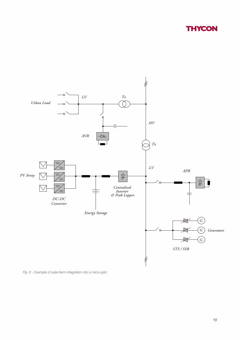
Solar-farms in Micro-gridsSolar farms exist in various sizes ranging from stand-alone utility-scale installations to small community or domestic systems. Thycon offers a wide range of PE equipment either for connecting solar-farms to the national grid or integrating them into micro-grids. Fig. 6 shows an example of a micro-grid with the various equipments required for Power Quality.
Peak-lopping: Thanks to the DC distribution network, excess energy can be stored in batteries and supplied to the grid at times of excessive demand or temporary drops in irradiation (Figs 3 & 6). The batteries are typically housed centrally along with the Solar Inverter. Thycon Peak Loppers can also be retro-fitted to existing solar farms even if based on AC intra-grid distribution (not shown).
Power Factor Correction: The Thycon Solar Inverter operates at unity PF and can compensate for inductive lines at the PCC. Where the line is operated at a particularly poor PF, additional compensation can be optionally provided at the PCC using a Thycon APR (active power regulator) or TCR-FC (thyristor controller reactor and fixed capacitor – see Fig. 6) both of which allow seamless leading and lagging power factor control.
Harmonic Attenuation: The inherent PF correction of the Thycon Inverter also attenuates harmonics. Where excessive harmonic levels are present at the PCC caused by grid-connected loads, passive harmonic filters are optionally available (not shown).
Fig. 4 - Thycon MPPT
9
On
- sta
te v
olta
ge (V
)Current
Solid State Switches: These are various types of switches based on semiconductors as opposed to mechanical contacts. They include:• SSI (Solid State Interrupter)• SSL (Solid State Limiter)• SSB (Solid State Breaker)• SST (Solid State Transfer switch)• HSEF (High Speed Electronic Fuse)• HSEBF (High Speed Electronic Breaker and
Fuse).
SSBs, for instance, can clear faults in fractions of a millisecond as opposed to the 100ms required by mechanical breakers thus reducing the prospective fault currents to one tenth of the normal levels which can significantly impact the cable sections required and hence installation costs. Because of the reduction of fault levels and the absence of arcing, solid state switches require no maintenance.
Redundant Solar Inverters: the main SI can be optionally backed up by a second inverter with a separate controller for additional security.
Power Limiter: The solar choppers have a programmable power limit adjustable from 0 to
100%. The operator can determine the absolute maximal power that any array can supply (to the chopper’s maximal rating).
Monitoring: All Thycon power conditioners have an RJ45 interface allowing optional remote SCADA monitoring of the following parameters: • string power and currents• total TSI o/p power (active and reactive) • grid voltage and frequency • battery voltage, temperature and state of charge• ambient and heat-sink temperatures.
SummaryThycon’s innovative SEMS is designed for the highest flexibility and efficiency coupled with lowest harmonic distortion and EMI. It allows the lowest capital and operating costs by minimising the complexity of distributed systems and allowing a modular approach to upgrading power management functionality.Thycon’s long experience of power inverters and energy storage for high-power uninterruptible power supplies, together with its range of power conditioners for PF and THD management, make Thycon a key supplier of regulation equipment to the solar energy industry.
Fig. 5 - Comparison of conduction (on-state) voltages for 3600A/1700V Infineon thyristor and IGBT
10
Fig. 6 - Example of solar-farm integration into a micro-grid

11
DC-DC CONVERTER
Input power 40kW 80kW 120kWInput current 100A 200A 300AMPPT voltage range 300-600VDCRipple <3%
Output voltage <806VDCEfficiency (%)
Peak 98.2 98,4 98,4CEC 97.7 98,1 98,1Euro 97.1 97.6 97.7MPPT 99
Ambient temperature -20 to +60dCProtection category IP55Relative humidity 98%CoolingCubicle finishCubicle colour RAL 7035Mounting Wall/Pole/PadGalvanic isolation Optional
Communication
Monitoring Earth fault
Compliance
Dimensions (w x d x h) (mm) 500 x 210 x 500 600 x 210 x 600 760 x 300 x 760
InputInput power 1MW 1,5MW 3MWDC voltage <806VDC
Frequency 50HzFrequency variation +/- 3HzPower factor >0.98THID <5% of input powerEfficiency
Peak 99.2 99.2 99.4CEC 98.8 98.8 99.1Euro 98.2 98.4 98.7
Ambient temperature -20 to +60dCProtection category IP22Relative humidity 98%Cooling Fan forcedCubicle finish Powder coatedCubicle colour RAL 7035Galvanic isolation Optional
Communication
Compliance
Dimensions (w x d x h) (mm) 1800 x 1000 x 2000 1800 x 1000 x 2000 3000 x 1000 x 2000
Technical data
Fan forced (temperature dependant)Powder coated (Stainless steel opt.)
Modbus/Jbus protocol over RS232 & RS482/485Modbus TCP/IP over ethernet
UL1741, IEEE1547, EN61000-6-2, EN61000-6-4
Modbus/Jbus protocol over RS232 & RS482/485Modbus TCP/IP over ethernet
UL1741, AS4777, IEEE1547, EN61000-6-2, EN61000-6-4, IEEE519
Published by ThyconBRO0020
THYCON INDUSTRIAL PTY LTD
20 AUDREY AVE COBURG
3058 VIC AUSTRALIA
PH 61 3 9319 9000
FAX 61 3 9319 9001
ABN 17 068 011 049
EMAIL [email protected]
WEB www.thycon.com.au
24-HOUR SERVICE 1800 670 700