Embed Size (px)
Citation preview
An- Najah National University Faculty of Graduate Studies
Solar Energy Refrigeration by Liquid-Solid Adsorption Technique
By
Watheq Khalil Said Hussein
Supervisor Dr. Abdelrahim Abusafa
Co-Supervisor Dr. Imad Ibrik
Submitted in Partial Fulfillment of the Requirements for the Degree of Master of Science in Clean Energy and Energy Conservation Engineering, Faculty of Graduate Studies, An-Najah University, Nablus – Palestine.
2008

iii
TO MY HOLLY LAND

iv
Acknowledgment
I would like to express my sincerest gratitude to my
supevisor Dr. Abdelrahim Abusafa who has always been
providing kindest support, encouragement, and guidance
throughout the accomplishment of this dissertation. I would like
also to thank Dr. Imad Ibrik, whom I can refer to as my second
supervisor; he has given me an opportunity to learn more in this
work. I also like to thank my wife, my parents and my family for
their encouragement. Lastly, I would like to thank my friends and
colleagues in clean energy and conservation engineering program
for their encouragement.
v
قـرار اإل
:أنا الموقع أدناه مقدم الرسالة التي تحمل العنوان
Solar Energy Refrigeration by Liquid-Solid Adsorption Technique
التبريد بواسطة الطاقة الشمسية باستخدام تقنية االدمصاص
اص، باستثناء مـا تمـت اقر بأن ما اشتملت عليه هذه الرسالة إنما هي نتاج جهدي الخ
اإلشارة إليه حيثما ورد، وان هذه الرسالة ككل، أو أي جزء منها لم يقدم من قبل لنيل أية درجة
.علمية أو بحث علمي أو بحثي لدى أية مؤسسة تعليمية أو بحثية أخرى
Declaration
The work provided in this thesis, unless otherwise referenced, is the
researcher's own work, and has not been submitted elsewhere for any other
degree or qualification.
:Student's name :اسم الطالب
:Signature :التوقيع
:Date :التاريخ
vi
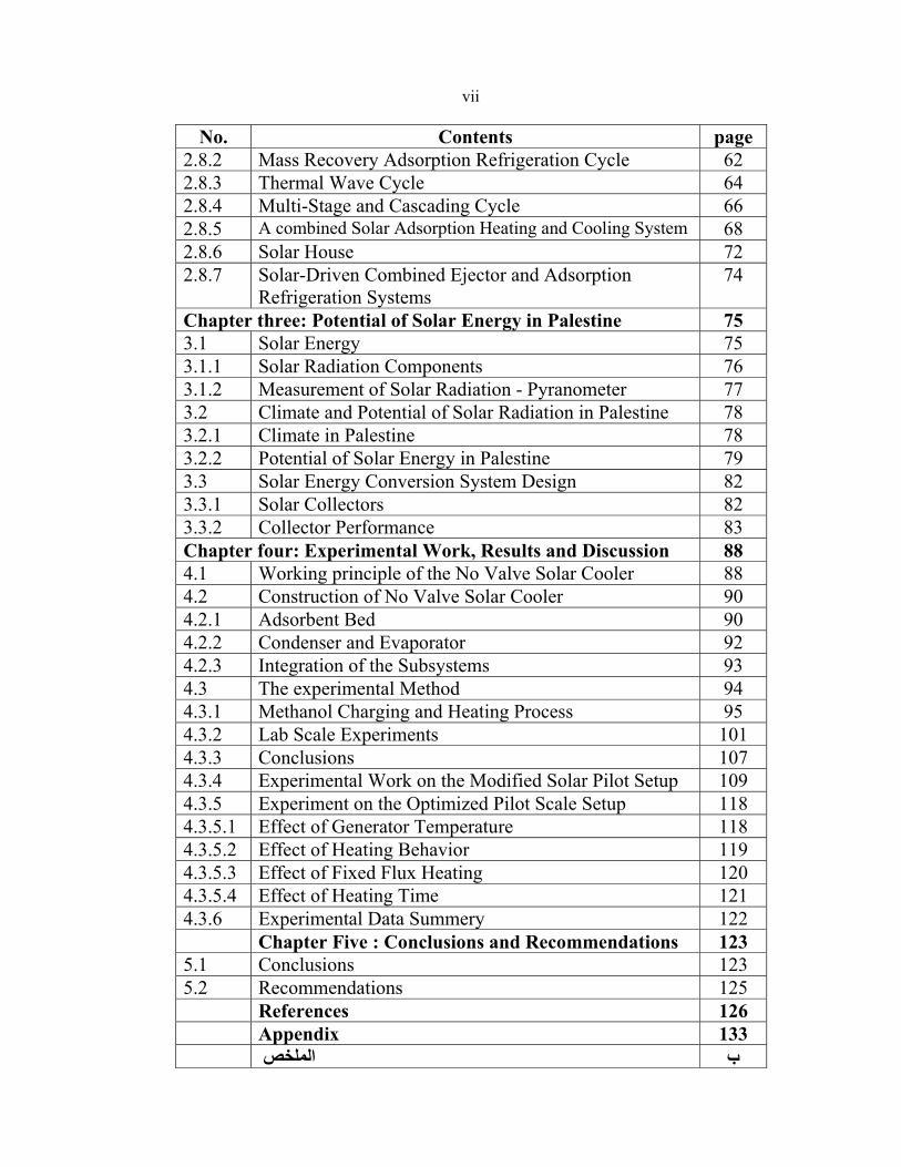
TABLE OF CONTENTS
Page Contents No. iv Acknowledgment vDeclaration vi TABLE OF CONTENTS
viii LIST OF TABLES ix LIST OF FIGURES xi Abstract 1 Introduction 3 Chapter One : Solar Cooling 3 Refrigeration Definition 1.1 4 Solar Cooling Options and Technologies 1.2 4 Solar Cooling Path 1.3 7 Cycle Efficiency 1.4 8 Solar Collector Efficiency 1.5 12Photovoltaic Efficiency1.6 13 System Efficiency 1.7 14 Solar Cooling Technologies 1.8 15 Thermal – Driven system 1.8.1 15 Absorption Refrigeration Cycle 1.8.1.1 19 Adsorption Refrigeration Cycle 1.8.1.2 21 Chemical reaction (solid-sorption) refrigeration cycle 1.8.1.3 23 Desiccant Refrigeration System 1.8.1.4 26 Ejector Refrigeration Cycle 1.8.1.5 28 Rankin-Driven Refrigeration Cycle 1.8.1.6 30 Electricity (Photovoltaic) driven system 1.8.2 33 Chapter Two : Solar Adsorption Refrigeration 33 History and Advantages 2.1 35 System Description 2.2 37 Principle of Adsorption 2.3 39 Selection of Adsorbent / Adsorbate Pair 2.4 48 Operation and Analysis of the Adsorption Cycle 2.5 51 Coefficient of Performance (COP) 2.6 54 The Effects of Collector and Environment Parameters
on the Performance of a Solar Powered Adsorption Refrigeration
2.7
54 Parametric Effects 2.7.1 57 Environmental Effects 2.7.2 60 Solar Adsorption Cooling Technologies 2.8 60Heat Recovery Adsorption Refrigeration Cycle2.8.1
vii
page Contents No. 62 Mass Recovery Adsorption Refrigeration Cycle 2.8.2 64 Thermal Wave Cycle 2.8.3 66 Multi-Stage and Cascading Cycle 2.8.4 68A combined Solar Adsorption Heating and Cooling System 2.8.5 72 Solar House 2.8.6 74 Solar-Driven Combined Ejector and Adsorption
Refrigeration Systems 2.8.7
75 Chapter three: Potential of Solar Energy in Palestine75 Solar Energy 3.1 76 Solar Radiation Components 3.1.1 77 Measurement of Solar Radiation - Pyranometer 3.1.2 78 Climate and Potential of Solar Radiation in Palestine 3.2 78 Climate in Palestine 3.2.1 79 Potential of Solar Energy in Palestine 3.2.2 82 Solar Energy Conversion System Design 3.3 82 Solar Collectors 3.3.1 83 Collector Performance 3.3.2 88 Chapter four: Experimental Work, Results and Discussion 88 Working principle of the No Valve Solar Cooler 4.1 90 Construction of No Valve Solar Cooler 4.2 90 Adsorbent Bed 4.2.1 92 Condenser and Evaporator 4.2.2 93 Integration of the Subsystems 4.2.3 94 The experimental Method 4.3 95 Methanol Charging and Heating Process 4.3.1
101 Lab Scale Experiments 4.3.2 107Conclusions 4.3.3 109 Experimental Work on the Modified Solar Pilot Setup 4.3.4 118 Experiment on the Optimized Pilot Scale Setup 4.3.5 118 Effect of Generator Temperature 4.3.5.1 119 Effect of Heating Behavior 4.3.5.2 120 Effect of Fixed Flux Heating 4.3.5.3 121 Effect of Heating Time 4.3.5.4 122 Experimental Data Summery 4.3.6 123 Chapter Five : Conclusions and Recommendations 123 Conclusions 5.1 125 Recommendations 5.2 126 References 133 Appendix الملخص ب
viii
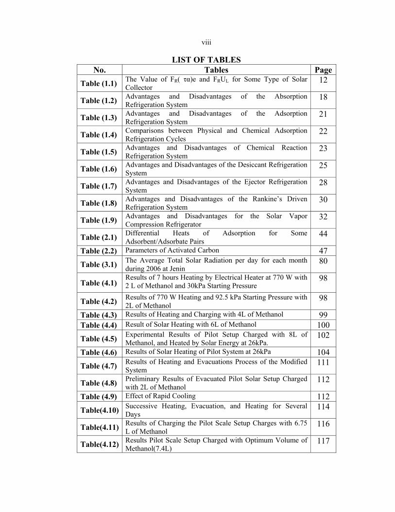
LIST OF TABLES PageTables No.
12 The Value of FR( τα)e and FRUL for Some Type of Solar Collector Table (1.1)
18 Advantages and Disadvantages of the Absorption Refrigeration System Table (1.2)
21 Advantages and Disadvantages of the Adsorption Refrigeration System Table (1.3)
22 Comparisons between Physical and Chemical Adsorption Refrigeration Cycles Table (1.4)
23 Advantages and Disadvantages of Chemical Reaction Refrigeration System Table (1.5)
25 Advantages and Disadvantages of the Desiccant Refrigeration System Table (1.6)
28 Advantages and Disadvantages of the Ejector Refrigeration System Table (1.7)
30 Advantages and Disadvantages of the Rankine’s Driven Refrigeration System Table (1.8)
32 Advantages and Disadvantages for the Solar Vapor Compression Refrigerator Table (1.9)
44 Differential Heats of Adsorption for Some Adsorbent/Adsorbate Pairs Table (2.1)
47 Parameters of Activated Carbon Table (2.2) 80 The Average Total Solar Radiation per day for each month
during 2006 at Jenin Table (3.1)
98 Results of 7 hours Heating by Electrical Heater at 770 W with 2 L of Methanol and 30kPa Starting Pressure Table (4.1)
98 Results of 770 W Heating and 92.5 kPa Starting Pressure with 2L of Methanol Table (4.2)
99 Results of Heating and Charging with 4L of Methanol Table (4.3) 100 Result of Solar Heating with 6L of Methanol Table (4.4) 102 Experimental Results of Pilot Setup Charged with 8L of
Methanol, and Heated by Solar Energy at 26kPa. Table (4.5)
104 Results of Solar Heating of Pilot System at 26kPa Table (4.6) 111 Results of Heating and Evacuations Process of the Modified
System Table (4.7)
112 Preliminary Results of Evacuated Pilot Solar Setup Charged with 2L of Methanol Table (4.8)
112Effect of Rapid Cooling Table (4.9) 114 Successive Heating, Evacuation, and Heating for Several
Days Table(4.10)
116 Results of Charging the Pilot Scale Setup Charges with 6.75 L of Methanol Table(4.11)
117 Results Pilot Scale Setup Charged with Optimum Volume of Methanol(7.4L) Table(4.12)
ix
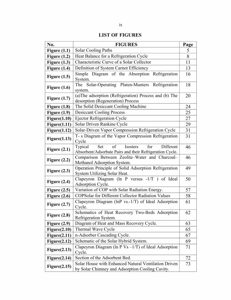
LIST OF FIGURES
No. FIGURES Page Figure (1.1) Solar Cooling Paths 5 Figure (1.2) Heat Balance for a Refrigeration Cycle 8Figure (1.3) Characteristic Curve of a Solar Collector 11 Figure (1.4) Definition of System Carnot Efficiency 13
Figure (1.5) Simple Diagram of the Absorption Refrigeration System.
16
Figure (1.6) The Solar-Operating Platen-Munters Refrigeration system.
18
Figure (1.7) (a)The adsorption (Refrigeration) Process and (b) The desorption (Regeneration) Process
20
Figure (1.8) The Solid Desiccant Cooling Machine 24Figure (1.9) Desiccant Cooling Process 25 Figure(1.10) Ejector Refrigeration Cycle 27 Figure(1.11) Solar Driven Rankine Cycle 29 Figure(1.12) Solar-Driven Vapor Compression Refrigeration Cycle 31
Figure(1.13) T- s Diagram of the Vapor Compression Refrigeration Cycle
31
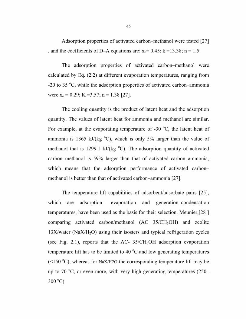
Figure (2.1) Typical Set of Isosters for Different Absorbent/Adsorbate Pairs and their Refrigeration Cycle.
46
Figure (2.2) Comparison Between Zeolite–Water and Charcoal–Methanol Adsorption System.
46
Figure (2.3) Operation Principle of Solid Adsorption Refrigeration System Utilizing Solar Heat.
49
Figure (2.4) Clapeyron Diagram (ln P versus -1/T ) of Ideal Adsorption Cycle.
50
Figure (2.5) Variation of COP with Solar Radiation Energy. 57 Figure (2.6) COPSolar for Different Collector Radiation Values 58
Figure (2.7) Clapeyron Diagram (lnP vs.-1/T) of Ideal Adsorption Cycle.
61
Figure (2.8) Schematics of Heat Recovery Two-Beds Adsorption Refrigeration System.
62
Figure (2.9) Diagram of Heat and Mass Recovery Cycle. 63 Figure(2.10) Thermal Wave Cycle 65 Figure(2.11) n-Adsorber Cascading Cycle. 67Figure(2.12) Schematic of the Solar Hybrid System. 69
Figure(2.13) Clapeyron Diagram (ln P Vs –1/T) of Ideal Adsorption Cycle.
71
Figure(2.14) Section of the Adsorbent Bed. 72
Figure(2.15) Solar House with Enhanced Natural Ventilation Driven by Solar Chimney and Adsorption Cooling Cavity.
73
x
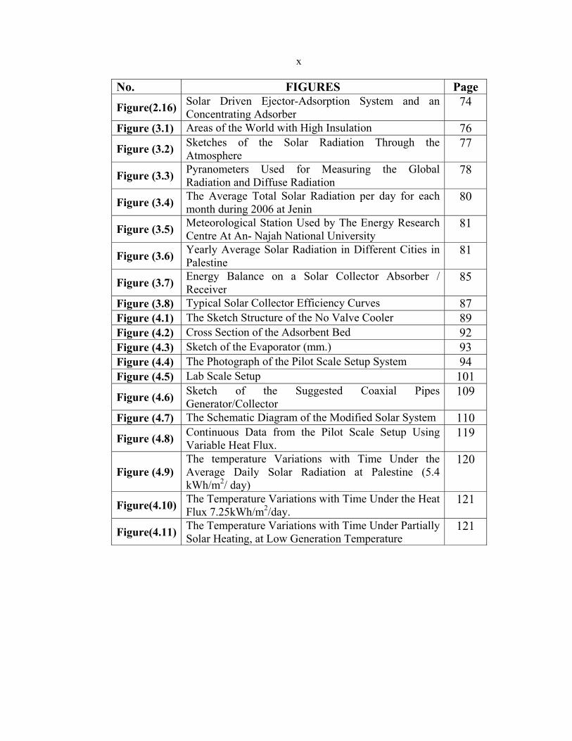
No. FIGURES Page
Figure(2.16) Solar Driven Ejector-Adsorption System and an Concentrating Adsorber
74
Figure (3.1) Areas of the World with High Insulation 76
Figure (3.2) Sketches of the Solar Radiation Through the Atmosphere
77
Figure (3.3) Pyranometers Used for Measuring the Global Radiation and Diffuse Radiation
78
Figure (3.4) The Average Total Solar Radiation per day for each month during 2006 at Jenin
80
Figure (3.5) Meteorological Station Used by The Energy Research Centre At An- Najah National University
81
Figure (3.6) Yearly Average Solar Radiation in Different Cities in Palestine
81
Figure (3.7) Energy Balance on a Solar Collector Absorber / Receiver
85
Figure (3.8) Typical Solar Collector Efficiency Curves 87Figure (4.1) The Sketch Structure of the No Valve Cooler 89 Figure (4.2) Cross Section of the Adsorbent Bed 92 Figure (4.3) Sketch of the Evaporator (mm.) 93 Figure (4.4) The Photograph of the Pilot Scale Setup System 94 Figure (4.5) Lab Scale Setup 101
Figure (4.6) Sketch of the Suggested Coaxial Pipes Generator/Collector
109
Figure (4.7) The Schematic Diagram of the Modified Solar System 110
Figure (4.8) Continuous Data from the Pilot Scale Setup Using Variable Heat Flux.
119
Figure (4.9) The temperature Variations with Time Under the Average Daily Solar Radiation at Palestine (5.4 kWh/m2/ day)
120
Figure(4.10) The Temperature Variations with Time Under the Heat Flux 7.25kWh/m2/day.
121
Figure(4.11) The Temperature Variations with Time Under Partially Solar Heating, at Low Generation Temperature
121
xi
Solar Energy Refrigeration by Liquid-Solid Adsorption Technique
By Watheq Khalil Said Hussein
Supervisor Dr. Abdelrahim Abusafa
Co-Supervisor Dr. Imad Ibrik
Abstract
The design, construction and operation of a solid adsorption solar
cooler are presented in this work. Granular activated carbon-methanol as
the adsorbent /adsorbate pair was used. The System has three important
components: collector/adsorber, condenser and evaporator.
A flat plate type collector made of stainless steel with effective
exposed area of 0.95m² was used. Two types of condensers were tested, the
first one was a helical copper tube immersed in water tank and the other
one was a finned stainless steel tube.
Solar radiation was simulated using an electrical heater regulated by
a solid state relay and potentiometer. The experimental work was focused
on optimizing the suitable amount of activated carbon/methanol pairs, the
influence of regenerator temperature, and the influence of solar flux on the
performance of the system.
It was found that regenerator temperature greater than 100 °C was
necessary to release methanol from the activated carbon.
The operating pressure was also found to be an important parameter
to achieve cooling effect; the system pressure must be less than 20kPa
absolute.
xii
As the adsorbent bed is the heart of such system, and its
characteristics directly affected the performance of the system, the
experimental work showed that the adsorbent bed which was used in this
study didn't achieve the best results expected, therefore another adsorbent
bed with hollow tubes generator was suggested, it was found that in this
type of generator is easier to control the leakage and the pressure inside the
system.
The type of the condenser and its length was found to be important
parameters that affect the performance of the used system. The condenser
length should be as short as possible, however, the condenser tube should
be straight pipe with fins and without any curvatures to prevent pressure
drop in the system.
In most cases, the water temperature of 10 °C was obtained using the
system for air-conditioning, food and vaccines preservation, and for
producing chilled water. The obtained temperature was effected directly by
the heat flux applied and the heating period. The optimum heating period
was found to be at least 5 hours, while the cooling period was more than 10
hours.
In a Lab scale setup solar cooler, it was found that the evaporator
volume has a significant effect on the performance of such system; the
evaporator volume should not be much larger than the maximum methanol
volume charged in the system. The maximum methanol adsorption capacity
of the used activated carbon was found to be 0.26 kg methanol / kg
activated carbon.
1
Introduction
Everywhere in our world, refrigeration is a major energy user. In
poor areas, “off grid” refrigeration is a critically important need. Both of
these considerations point the way toward refrigeration using renewable
energy, as part of a sustainable way of life. Solar-powered refrigeration is a
real and exciting possibility.
Due to the increasing concentration of greenhouse gases and climate
changes, the need for renewable energy sources is greater than ever. This
has now attracted attention from the countries that has set up targets to
increase the share of renewable energy supply in the world in order to
reduce greenhouse gas emissions.
Today about 82% of the world’s primary-energy requirements are
covered by coal, natural gas, oil and uranium. Approximately 12% comes
from biomass and 6% from hydroelectric power. A reduction of greenhouse
gases throughout the world of about 50 % is required in the next 50-100
years, according to many experts. In order to achieve this, a reduction of
greenhouse gas emissions of approximately 90% per capita in the industrial
countries, will be necessary. If we shall be able to change our energy
supply system and reduce greenhouse gases, we need to use renewable
energy sources, and solar energy is one of the most environmentally safe
energy sources.
Energy supply to refrigeration and air-conditioning systems
constitutes a significant role in the world. The International Institute of
Refrigeration (IIR) has estimated that approximately 15% of all electricity
2
produced worldwide is used for refrigeration and air-conditioning
processes of various kinds [1].
The cooling load is generally high when solar radiation is high.
Together with existing technologies, solar energy can be converted to both
electricity and heat; either of which can be used to power refrigeration
systems. Being provided with a good electricity grid worldwide, people are,
however, more likely to choose a vapor compression air-conditioning
system.
Palestine climate has an attractive potential for solar energy
application. The overall aim of this study is to develop a solar powered
solid adsorption cooler using locally available technologies. Many
experiments were done to optimize the best design, the suitable conditions,
and the influence of temperature levels and different power fluxes on the
solar cooler performance. Despite the greatest effort needed to make the
system sealed, the system was very simple, needs no maintenance and has
no moving parts consequently it is noiseless.
3
Chapter One Solar Cooling
1.1 Refrigeration Definition
In general, refrigeration is defined as any process of heat removal.
More specifically, Refrigeration is defined as the branch of science that
deals with the process of reducing and maintaining the temperature of a
space or material below the temperature of the surroundings.
To accomplish this, heat must be removed from the body being
refrigerated and transferred to another body whose temperature is below
that of the refrigerated body. Removing heat from inside a refrigerator is
somewhat like removing water from a leaking canoe. A sponge may be
used to soak up the water. The sponge is held over the side, squeezed, and
the water is released over board. The operation may be repeated as often as
necessary to transfer the water from the canoe into the lake. In a
refrigerator, heat instead of water is transferred[2].
Since the heat removed from the refrigerated body is transferred to
another body, it is evident that refrigerating and heating are actually
opposite ends of the same process. Often only, the desired result
distinguishes one from the other. Therefore, solar energy may be used for
cooling. This is usually done by using absorption or adsorption system
refrigeration. These systems require a heat source. The heat is used to drive
the refrigerant out of another substance which has the opportunity to
release it when they are heated and to adsorb it when be cooled. The sun
can supply the heat required to operate adsorption or absorption cycles.
4
1.2 Solar Cooling Options and Technologies
The concept of ‘solar cooling path’ from the energy source to the
cooling service, is introduced in this chapter. Before going into detail for
each solar-driven refrigeration system, definitions, suitable efficiency
terms, and thermodynamic limitations of solar cooling are described.
Subsequently, an overview of possible solar-driven refrigeration and air-
conditioning options are presented, including some possible and existing
cooling cycles. The advantages and disadvantages of each solar cooling
system are also compared.
1 .3 Solar Cooling Path
The solar cooling system is generally comprised of three sub-
systems: the solar energy conversion system, refrigeration system, and the
cooling load. The appropriate cycle in each application depends on cooling
demand, power, and the temperature levels of the refrigerated object, as
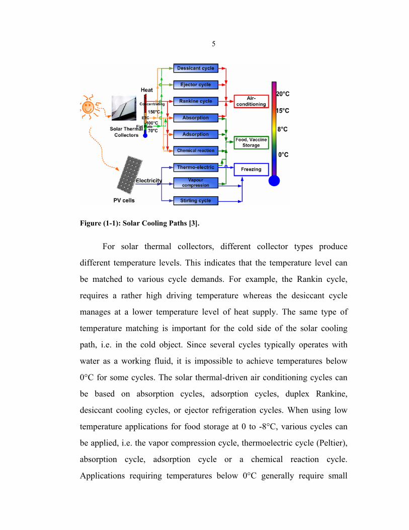
well as the environment. A number of possible “paths” from solar energy to
“cooling services” are shown in Figure1-1. Starting from the inflow of
solar energy there are obviously two significant paths to follow; solar
thermal collectors to heat or PV cells to electricity [3].
5
Figure (1-1): Solar Cooling Paths [3].
For solar thermal collectors, different collector types produce
different temperature levels. This indicates that the temperature level can
be matched to various cycle demands. For example, the Rankin cycle,
requires a rather high driving temperature whereas the desiccant cycle
manages at a lower temperature level of heat supply. The same type of
temperature matching is important for the cold side of the solar cooling
path, i.e. in the cold object. Since several cycles typically operates with
water as a working fluid, it is impossible to achieve temperatures below
0°C for some cycles. The solar thermal-driven air conditioning cycles can
be based on absorption cycles, adsorption cycles, duplex Rankine,
desiccant cooling cycles, or ejector refrigeration cycles. When using low
temperature applications for food storage at 0 to -8°C, various cycles can
be applied, i.e. the vapor compression cycle, thermoelectric cycle (Peltier),
absorption cycle, adsorption cycle or a chemical reaction cycle.
Applications requiring temperatures below 0°C generally require small
6
storage volumes e.g., freezing boxes. A suitable cycle for this application
has proved to be the PV-driven vapor compression cycle, or a PV-driven
Sterling cycle. The double effect absorption cycle, adsorption cycle and
chemical reaction cycle can also be used, especially for larger storage
volumes, i.e. ice production [ 1] .
Typically for the cycles in Figure 1-1 are that, the efficiency of the
electricity-driven refrigeration cycles is quite high but they require
photovoltaic panels and batteries, which are expensive. Heat driven cycles
on the other hand, are less efficient, but the thermal solar collectors may
reach much higher conversion efficiencies than the PV’s, even though the
output is heat, not electricity. Therefore, the question is: which path
provides the highest overall efficiency? One example: System 1, a heat
driven cycle with a cycle COP of 0.7 receives its heat from a solar collector
with 80% efficiency, System 2, a vapor compression refrigeration cycle
with a COP of 4 receives its electricity from a PV array with an efficiency
of 15%. Which one gives the highest overall efficiency?
COPsolar= ηcollector,thx COPcycle = 0.7 x 0.8 = 0.56
COPsolar= ηcollector, pvx COPcycle = 0.15x 4.0= 0.6
The solar energy collection efficiency, ηcollector of both thermal
collectors and photovoltaic collectors is defined as the ratio of the rate of
useful thermal energy leaving the collector, to the useable solar irradiance
falling on the aperture area. Simply stated, collector efficiency is:
ηcoll = Quseful/ AaIa (1-1)
7
where:
Quseful = rate of (useful) energy output (W)
Aa = aperture area of the collector (m2)
Ia = solar irradiance falling on collector aperture (W/m2)
The COPsolar (coefficient of performance) is the ratio of the refrigeration
effect to the solar energy input (I), while the COPcycle is the ratio of the
refrigeration effect to the required input work to drive the refrigerator.
1.4 Cycle Efficiency
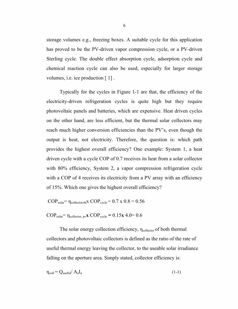
The performance of a refrigeration cycles is generally presented in
terms of a coefficient of performance, COP, illustrating how much energy
that heat can be removed from a cold space (Qe) for each unit of energy
expended (W or Qg) as in figure 1-2. The COP can be written differently,
depending on the type of drive energy. The frequently used definitions for
COP of an electricity/ work-driven system and thermally driven system are
shown in equation 1-2 and 1-3, respectively [4].
COPel = Qe / W (1-2)
COPthermal = Qe / Qg (1-3)
8
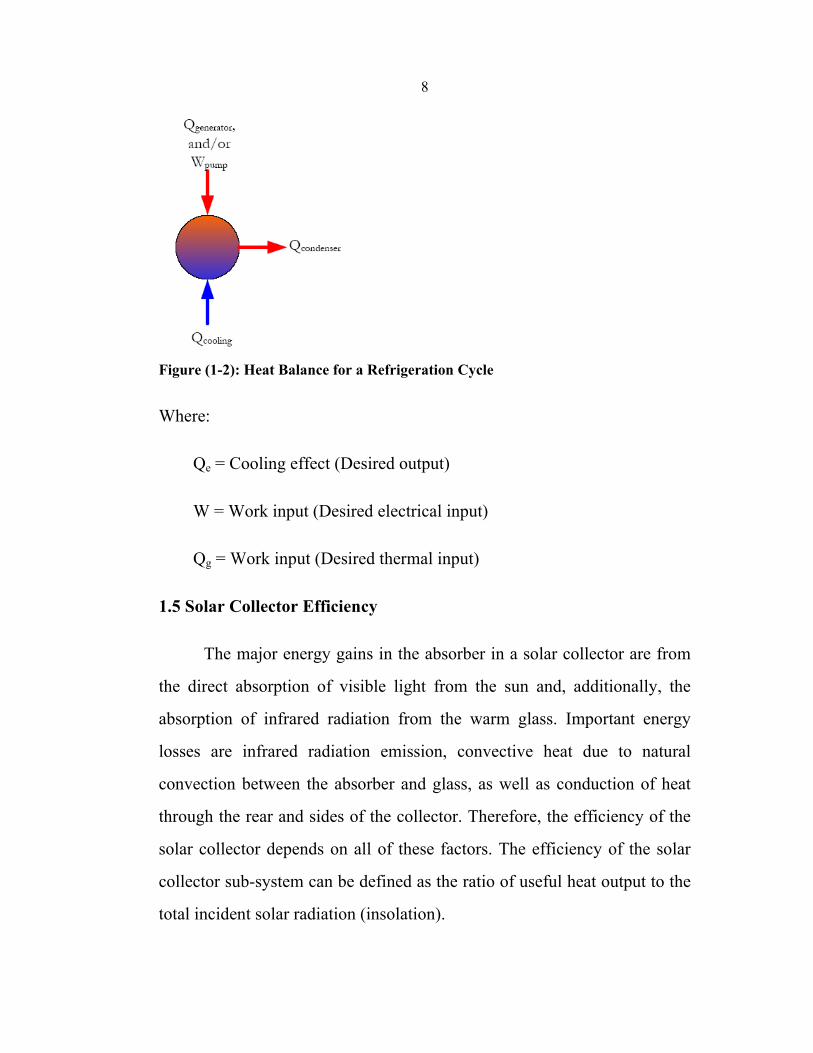
Figure (1-2): Heat Balance for a Refrigeration Cycle
Where:
Qe = Cooling effect (Desired output)
W = Work input (Desired electrical input)
Qg = Work input (Desired thermal input)
1.5 Solar Collector Efficiency
The major energy gains in the absorber in a solar collector are from
the direct absorption of visible light from the sun and, additionally, the
absorption of infrared radiation from the warm glass. Important energy
losses are infrared radiation emission, convective heat due to natural
convection between the absorber and glass, as well as conduction of heat
through the rear and sides of the collector. Therefore, the efficiency of the
solar collector depends on all of these factors. The efficiency of the solar
collector sub-system can be defined as the ratio of useful heat output to the
total incident solar radiation (insolation).
9
In the following efficiency definition, it is assumed that radiation is
in the hemispherical region, all rays reach the absorber, and the multiple
reflections between the cover and absorber are neglected. The solar
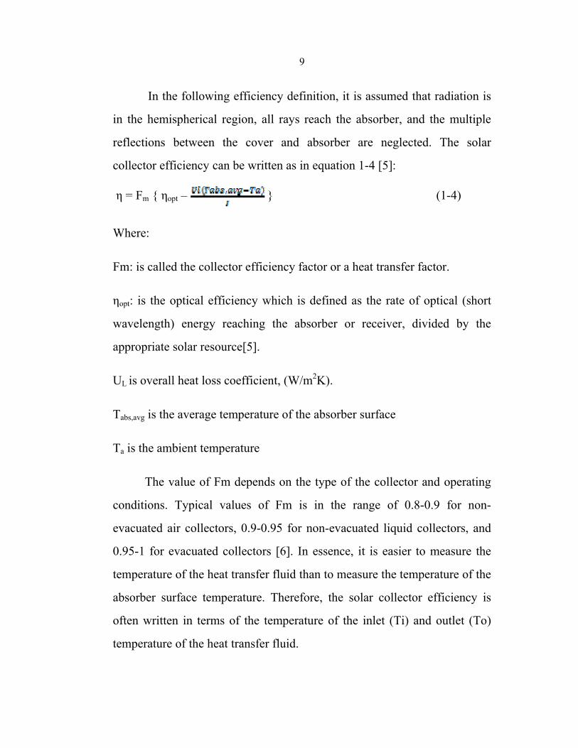
collector efficiency can be written as in equation 1-4 [5]:
η = Fm { ηopt – } (1-4)
Where:
Fm: is called the collector efficiency factor or a heat transfer factor.
ηopt: is the optical efficiency which is defined as the rate of optical (short
wavelength) energy reaching the absorber or receiver, divided by the
appropriate solar resource[5].
UL is overall heat loss coefficient, (W/m2K).
Tabs,avg is the average temperature of the absorber surface
Ta is the ambient temperature
The value of Fm depends on the type of the collector and operating
conditions. Typical values of Fm is in the range of 0.8-0.9 for non-
evacuated air collectors, 0.9-0.95 for non-evacuated liquid collectors, and
0.95-1 for evacuated collectors [6]. In essence, it is easier to measure the
temperature of the heat transfer fluid than to measure the temperature of the
absorber surface temperature. Therefore, the solar collector efficiency is
often written in terms of the temperature of the inlet (Ti) and outlet (To)
temperature of the heat transfer fluid.
10
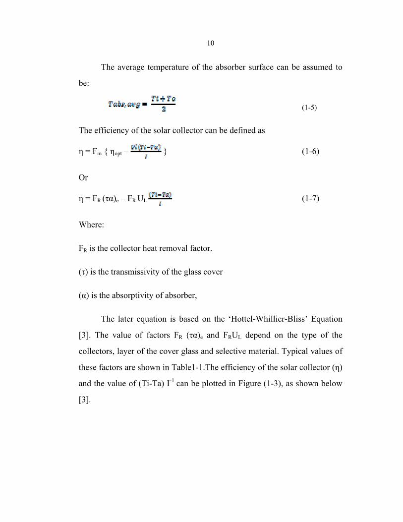
The average temperature of the absorber surface can be assumed to
be:
(1-5)
The efficiency of the solar collector can be defined as
η = Fm { ηopt – } (1-6)
Or
η = FR (τα)e – FR UL (1-7)
Where:
FR is the collector heat removal factor.
(τ) is the transmissivity of the glass cover
(α) is the absorptivity of absorber,
The later equation is based on the ‘Hottel-Whillier-Bliss’ Equation
[3]. The value of factors FR (τα)e and FRUL depend on the type of the
collectors, layer of the cover glass and selective material. Typical values of
these factors are shown in Table1-1.The efficiency of the solar collector (η)
and the value of (Ti-Ta) I-1 can be plotted in Figure (1-3), as shown below
[3].
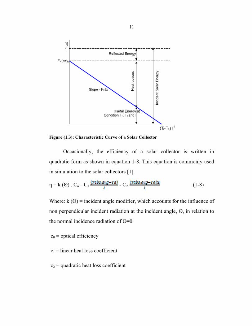
11
Figure (1.3): Characteristic Curve of a Solar Collector
Occasionally, the efficiency of a solar collector is written in
quadratic form as shown in equation 1-8. This equation is commonly used
in simulation to the solar collectors [1].
η = k (Θ) . Co – C1 - C2 (1-8)
Where: k (Θ) = incident angle modifier, which accounts for the influence of
non perpendicular incident radiation at the incident angle, Θ, in relation to
the normal incidence radiation of Θ=0
c0 = optical efficiency
c1 = linear heat loss coefficient
c2 = quadratic heat loss coefficient
12
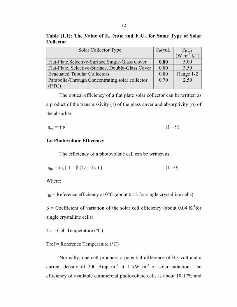
Table (1.1): The Value of FR (τα)e and FRUL for Some Type of Solar Collector
Solar Collector Type FR(τα)e FRUL (W m-2 K-1)
Flat-Plate,Selective-Surface,Single-Glass Cover 0.80 5.00 Flat-Plate, Selective-Surface, Double-Glass Cover 0.80 3.50 Evacuated Tubular Collectors 0.80 Range 1-2 Parabolic-Through Concentrating solar collector (PTC)
0.70 2.50
The optical efficiency of a flat plate solar collector can be written as
a product of the transmissivity (τ) of the glass cover and absorptivity (α) of
the absorber,
ηopt = τ α (1 – 9)
1.6 Photovoltaic Efficiency
The efficiency of a photovoltaic cell can be written as
ηpv = ηR [ 1 – β (TC – TR ) ] (1-10)
Where:
ηR = Reference efficiency at 0°C (about 0.12 for single crystalline cells)
β = Coefficient of variation of the solar cell efficiency (about 0.04 K-1for
single crystalline cells)
Tc = Cell Temperature (°C)
Tref = Reference Temperature (°C)
Normally, one cell produces a potential difference of 0.5 volt and a
current density of 200 Amp m-2 at 1 kW m-2 of solar radiation. The
efficiency of available commercial photovoltaic cells is about 10-17% and
13
they can produce 1-1.5 kWh m-2 per day. The current is proportional to the
light exposure area [7].
1.7 System Efficiency
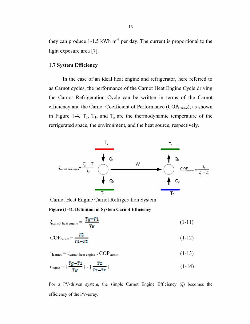
In the case of an ideal heat engine and refrigerator, here referred to
as Carnot cycles, the performance of the Carnot Heat Engine Cycle driving
the Carnot Refrigeration Cycle can be written in terms of the Carnot
efficiency and the Carnot Coefficient of Performance (COPCarnot), as shown
in Figure 1-4. T2, T1, and Tg are the thermodynamic temperature of the
refrigerated space, the environment, and the heat source, respectively.
Carnot Heat Engine Carnot Refrigeration System
Figure (1-4): Definition of System Carnot Efficiency
ξcarnot heat engine = (1-11)
COPcarnot = (1-12)
ηcarnot = ξcarnot heat engine . COPcarnot (1-13)
ηcarnot = { } . { } (1-14)
For a PV-driven system, the simple Carnot Engine Efficiency (ξ) becomes the
efficiency of the PV-array.
14
ηsystem,el = COPel ηpv (1-15)
Since the main energy source is free for solar cooling systems, the
term' solar fraction’ is better suited for demonstrating the overall
effectiveness of the system. Solar fraction is defined as the ratio of the total
solar energy used to the total energy used in the system.
Solar Fraction = Solar Energy Used in the System / Total Energy
Used in the System.
1.8 SOLAR COOLING TECHNOLOGIES
The solar-driven refrigeration system, as mentioned previously, is
mainly classified into two main groups depending on the energy supply:
thermal/work driven system and electricity (Photovoltaic) driven system,
each group can be classified as the following,
1. Thermal/work driven systems
• Absorption refrigeration cycle
• Adsorption refrigeration cycle
• Chemical reaction refrigeration cycle
• Desiccant cooling cycle
• Ejector refrigeration cycle
• Expansion refrigeration cycle
15
2. Electricity (Photovoltaic) driven system
• Sterling refrigeration cycle
• Thermo-electric refrigeration cycle
• Vapor compression refrigeration cycle
1.8.1 Thermal – driven systems
1.8.1.1 Absorption Refrigeration Cycle
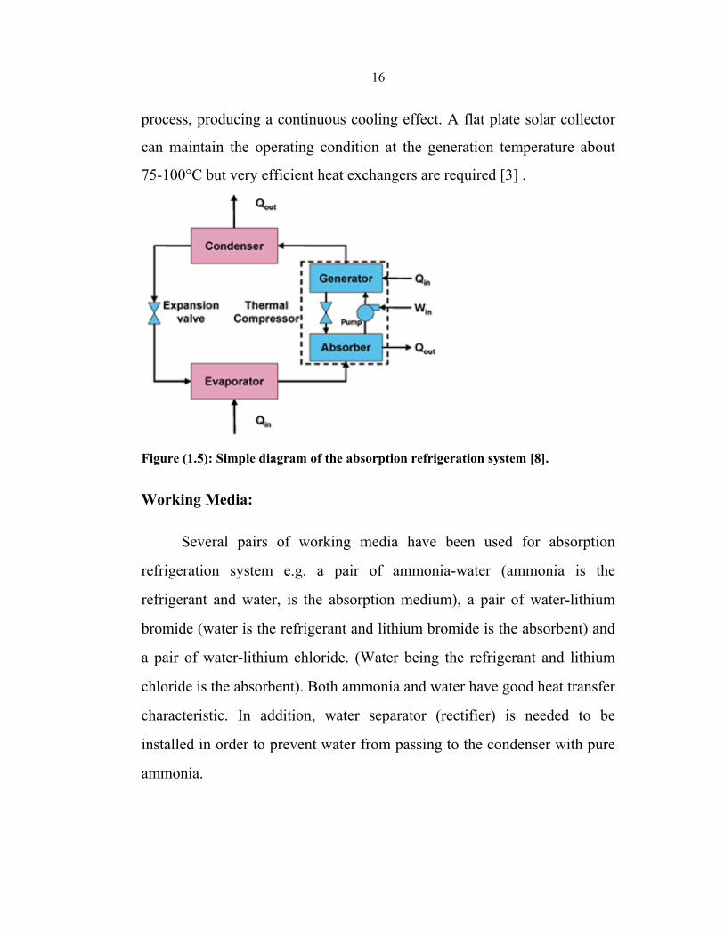
The main components of the absorption refrigeration system are an
absorber, generator, a condenser, an expansion valve, a heat exchanger and
a pump. The Simple diagram of the absorption refrigeration system shown
in Fig. 1.5. Two kinds of working medium are used at the same time in
refrigeration and absorption processes. The refrigerant vapor flows to the
condenser passing through a vapor-trap and condensed. Liquid refrigerant
from the condenser goes through an expansion valve while the pressure is
decreased to an evaporation pressure. At the evaporator, cooling effect is
achieved by the vaporization of the refrigerant at a low temperature.
Refrigerant vapor from the evaporator continues to an absorber and
dissolves in a weak refrigerant solution, and it becomes a stronger
refrigerant solution, which is called “rich solution”. A pump is the only
moving part in this system. The “rich solution” is pumped to a generator.
At the generator, the rich solution is heated up; the refrigerant is separated
from the solution. The refrigerant is vaporized and goes to the condenser
while the weak solution is passed through a heat exchanger and returned to
the absorber to absorb the refrigerant vapor. The refrigeration process and
the regeneration process operate at the same time as the continuous
16
process, producing a continuous cooling effect. A flat plate solar collector
can maintain the operating condition at the generation temperature about
75-100°C but very efficient heat exchangers are required [3] .
Figure (1.5): Simple diagram of the absorption refrigeration system [8].
Working Media:
Several pairs of working media have been used for absorption
refrigeration system e.g. a pair of ammonia-water (ammonia is the
refrigerant and water, is the absorption medium), a pair of water-lithium
bromide (water is the refrigerant and lithium bromide is the absorbent) and
a pair of water-lithium chloride. (Water being the refrigerant and lithium
chloride is the absorbent). Both ammonia and water have good heat transfer
characteristic. In addition, water separator (rectifier) is needed to be
installed in order to prevent water from passing to the condenser with pure
ammonia.
17
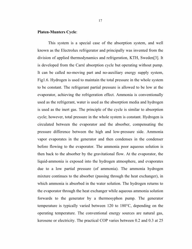
Platen-Munters Cycle:
This system is a special case of the absorption system, and well
known as the Electrolux refrigerator and principally was invented from the
division of applied thermodynamics and refrigeration, KTH, Sweden[3]. It
is developed from the Carré absorption cycle but operating without pump.
It can be called no-moving part and no-auxiliary energy supply system,
Fig1.6. Hydrogen is used to maintain the total pressure in the whole system
to be constant. The refrigerant partial pressure is allowed to be low at the
evaporator, achieving the refrigeration effect. Ammonia is conventionally
used as the refrigerant, water is used as the absorption media and hydrogen
is used as the inert gas. The principle of the cycle is similar to absorption
cycle; however, total pressure in the whole system is constant. Hydrogen is
circulated between the evaporator and the absorber, compensating the
pressure difference between the high and low-pressure side. Ammonia
vapor evaporates in the generator and then condenses in the condenser
before flowing to the evaporator. The ammonia poor aqueous solution is
then back to the absorber by the gravitational flow. At the evaporator, the
liquid-ammonia is exposed into the hydrogen atmosphere, and evaporates
due to a low partial pressure (of ammonia). The ammonia hydrogen
mixture continues to the absorber (passing through the heat exchanger), in
which ammonia is absorbed in the water solution. The hydrogen returns to
the evaporator through the heat exchanger while aqueous ammonia solution
forwards to the generator by a thermosyphon pump. The generator
temperature is typically varied between 120 to 180°C, depending on the
operating temperature. The conventional energy sources are natural gas,
kerosene or electricity. The practical COP varies between 0.2 and 0.3 at 25
18
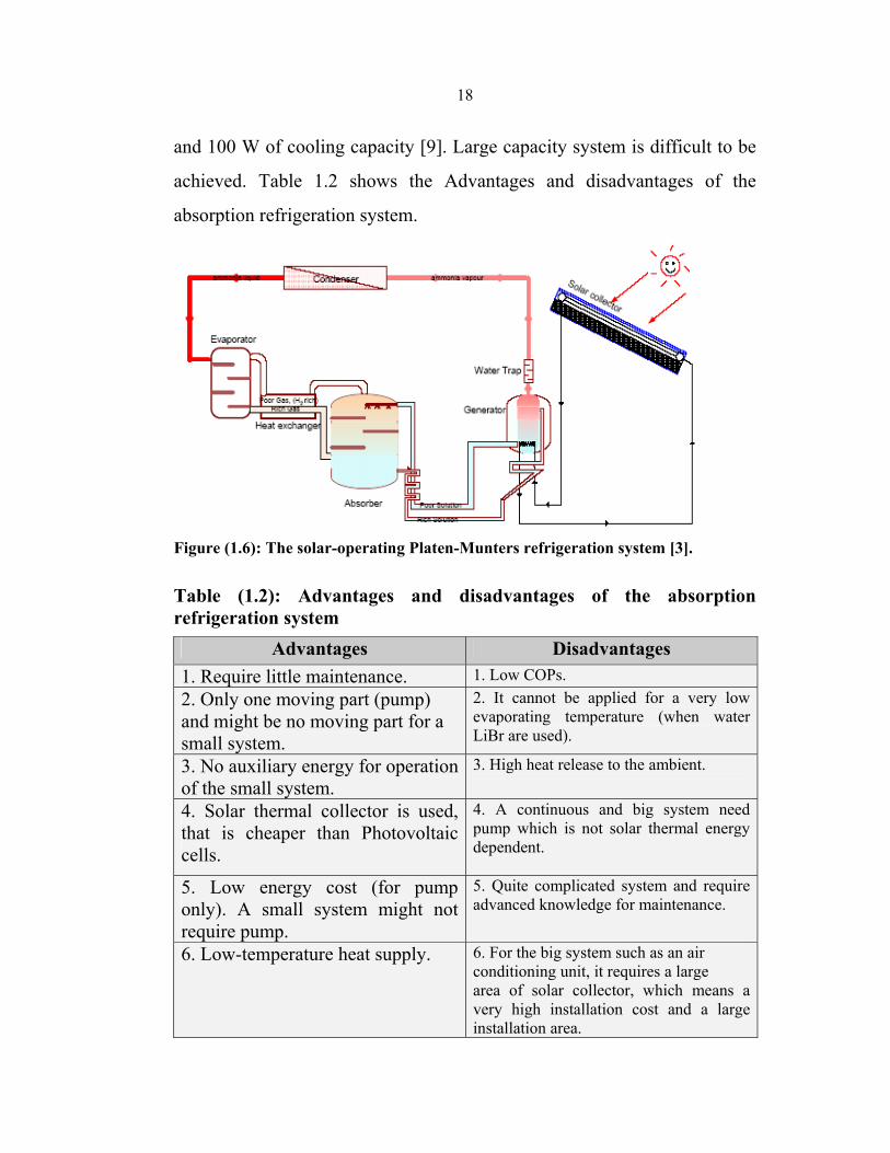
and 100 W of cooling capacity [9]. Large capacity system is difficult to be
achieved. Table 1.2 shows the Advantages and disadvantages of the
absorption refrigeration system.
Figure (1.6): The solar-operating Platen-Munters refrigeration system [3].
Table (1.2): Advantages and disadvantages of the absorption refrigeration system
Advantages Disadvantages 1. Require little maintenance. 1. Low COPs. 2. Only one moving part (pump) and might be no moving part for a small system.
2. It cannot be applied for a very low evaporating temperature (when water LiBr are used).
3. No auxiliary energy for operation of the small system.
3. High heat release to the ambient.
4. Solar thermal collector is used, that is cheaper than Photovoltaic cells.
4. A continuous and big system need pump which is not solar thermal energy dependent.
5. Low energy cost (for pump only). A small system might not require pump.
5. Quite complicated system and require advanced knowledge for maintenance.
6. Low-temperature heat supply. 6. For the big system such as an air conditioning unit, it requires a large area of solar collector, which means a very high installation cost and a large installation area.
19
1.8.1.2. Adsorption Refrigeration Cycle
An adsorption, also called a solid-sorption cycle, is a preferential
partitioning of substances from a gaseous or liquid phase onto a surface of
a solid substrate. This process involves the separation of a substance from
one phase to accumulate or concentrate on a surface of another substance.
An adsorbing phase is called an ‘adsorbent’. Material, which is
accumulated, concentrated or adsorbed in another surface, is called an
‘adsorbate’. The sticking process should not change any macroscopic form
of the adsorbent except the changing in adsorbent’s mass.
Both adsorption and absorption can be expressed in term of sorption
process. The adsorption process is caused by the Van der Vaals force
between adsorbate and atoms or molecules at the adsorbent surface. The
adsorbent is characterized by the surface and porosity. In the adsorption
refrigeration cycle, refrigerant vapor is not be compressed to a higher
temperature and pressure by the compressor but it is adsorbed by a solid
with a very high microscopic porosity. This process requires only thermal
energy, no mechanical energy requirement. The principles of the adsorption
process provide two main processes, adsorption or refrigeration and
desorption or regeneration. In case zeolite and water, as an example, the
refrigerant (water) is vaporized by, the heat from cooling space and the
generator (absorbent tank) is cooled by ambient air. The vapor from the
cooling space is leaded to the generator tank and absorbed by adsorbent
(zeolite). The rest of the water is cooled or frozen. In the regeneration
process, the zeolite is heated at a high temperature until the water vapor in
the zeolite is desorbed out, goes back and condenses in the water tank,
20
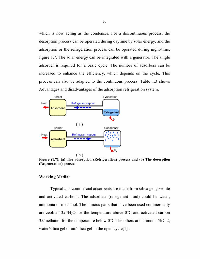
which is now acting as the condenser. For a discontinuous process, the
desorption process can be operated during daytime by solar energy, and the
adsorption or the refrigeration process can be operated during night-time,
figure 1.7. The solar energy can be integrated with a generator. The single
adsorber is required for a basic cycle. The number of adsorbers can be
increased to enhance the efficiency, which depends on the cycle. This
process can also be adapted to the continuous process. Table 1.3 shows
Advantages and disadvantages of the adsorption refrigeration system.
( a )
( b )
Figure (1.7): (a) The adsorption (Refrigeration) process and (b) The desorption (Regeneration) process
Working Media:
Typical and commercial adsorbents are made from silica gels, zeolite
and activated carbons. The adsorbate (refrigerant fluid) could be water,
ammonia or methanol. The famous pairs that have been used commercially
are zeolite‘13x’/H2O for the temperature above 0°C and activated carbon
35/methanol for the temperature below 0°C.The others are ammonia/SrCl2,
water/silica gel or air/silica gel in the open cycle[1] .
21
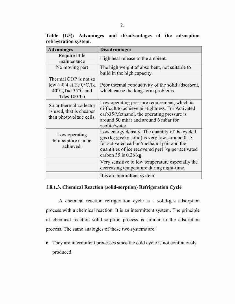
Table (1.3): Advantages and disadvantages of the adsorption refrigeration system. Advantages Disadvantages
Require little maintenance High heat release to the ambient.
No moving part
The high weight of absorbent, not suitable to build in the high capacity.
Thermal COP is not so low (~0.4 at Te 0°C,Tc
40°C,Tad 35°C and Tdes 100°C)
Poor thermal conductivity of the solid adsorbent, which cause the long-term problems.
Solar thermal collector is used, that is cheaper than photovoltaic cells.
Low operating pressure requirement, which is difficult to achieve air-tightness. For Activated carb35/Methanol, the operating pressure is around 50 mbar and around 6 mbar for zeolite/water.
Low operating temperature can be
achieved.
Low energy density. The quantity of the cycled gas (kg gas/kg solid) is very low, around 0.13 for activated carbon/methanol pair and the quantities of ice recovered per1 kg per activated carbon 35 is 0.26 kg.
Very sensitive to low temperature especially the decreasing temperature during night-time.
It is an intermittent system.
1.8.1.3. Chemical Reaction (solid-sorption) Refrigeration Cycle
A chemical reaction refrigeration cycle is a solid-gas adsorption
process with a chemical reaction. It is an intermittent system. The principle
of chemical reaction solid-sorption process is similar to the adsorption
process. The same analogies of these two systems are:
• They are intermittent processes since the cold cycle is not continuously
produced.
22
• They are heat-driven refrigeration cycles (The mechanical work is
required in some cases to blow out the vapor). The sorption latent heat
from the gas phase is the driving energy.
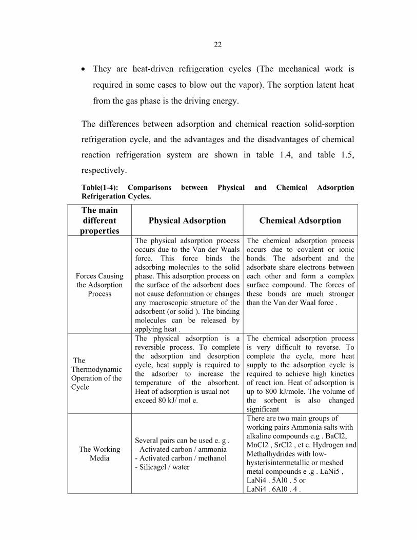
The differences between adsorption and chemical reaction solid-sorption
refrigeration cycle, and the advantages and the disadvantages of chemical
reaction refrigeration system are shown in table 1.4, and table 1.5,
respectively.
Table(1-4): Comparisons between Physical and Chemical Adsorption Refrigeration Cycles.
The main different
properties Physical Adsorption Chemical Adsorption
Forces Causing the Adsorption
Process
The physical adsorption process occurs due to the Van der Waals force. This force binds the adsorbing molecules to the solid phase. This adsorption process on the surface of the adsorbent does not cause deformation or changes any macroscopic structure of the adsorbent (or solid ). The binding molecules can be released by applying heat .
The chemical adsorption process occurs due to covalent or ionic bonds. The adsorbent and the adsorbate share electrons between each other and form a complex surface compound. The forces of these bonds are much stronger than the Van der Waal force .
The Thermodynamic Operation of the Cycle
The physical adsorption is a reversible process. To complete the adsorption and desorption cycle, heat supply is required to the adsorber to increase the temperature of the absorbent. Heat of adsorption is usual not exceed 80 kJ/ mol e.
The chemical adsorption process is very difficult to reverse. To complete the cycle, more heat supply to the adsorption cycle is required to achieve high kinetics of react ion. Heat of adsorption is up to 800 kJ/mole. The volume of the sorbent is also changed significant
The Working Media
Several pairs can be used e. g . - Activated carbon / ammonia - Activated carbon / methanol - Silicagel / water
There are two main groups of working pairs Ammonia salts with alkaline compounds e.g . BaCl2, MnCl2 , SrCl2 , et c. Hydrogen and Methalhydrides with low-hysterisintermetallic or meshed metal compounds e .g . LaNi5 , LaNi4 . 5Al0 . 5 or LaNi4 . 6Al0 . 4 .
23
Table (1.5): Advantages and disadvantages of chemical reaction refrigeration system Advantages Disadvantages Require little maintenance High heat release to the ambient. No moving part, it is a static system
Low COPs.
Low operating temperature can be Achieved.
Poor thermal conductivity of the solid adsorbent, which cause the long-term problems.
Solar thermal collector is used, that is cheaper than Photovoltaic cells.
The high weight of adsorbent, not suitable to build in a high capacity.
Large energy density. Low operating pressure at the lower
temperature, difficult to achieve air tightness.
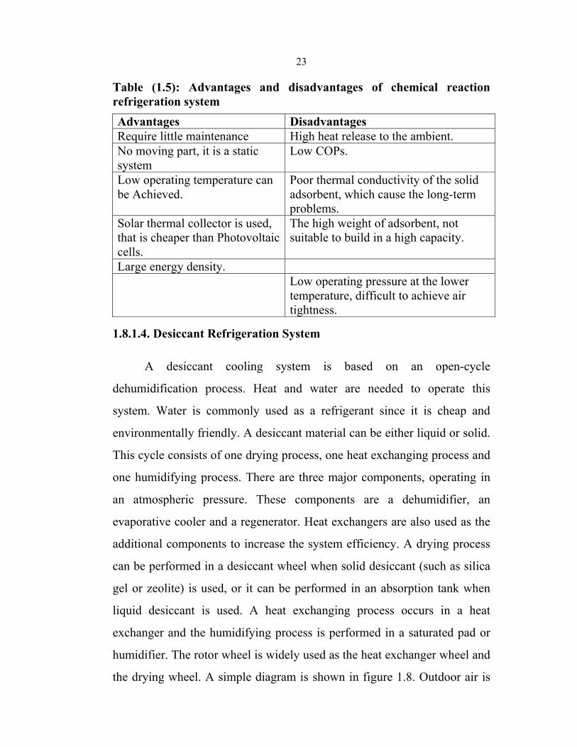
1.8.1.4. Desiccant Refrigeration System
A desiccant cooling system is based on an open-cycle
dehumidification process. Heat and water are needed to operate this
system. Water is commonly used as a refrigerant since it is cheap and
environmentally friendly. A desiccant material can be either liquid or solid.
This cycle consists of one drying process, one heat exchanging process and
one humidifying process. There are three major components, operating in
an atmospheric pressure. These components are a dehumidifier, an
evaporative cooler and a regenerator. Heat exchangers are also used as the
additional components to increase the system efficiency. A drying process
can be performed in a desiccant wheel when solid desiccant (such as silica
gel or zeolite) is used, or it can be performed in an absorption tank when
liquid desiccant is used. A heat exchanging process occurs in a heat
exchanger and the humidifying process is performed in a saturated pad or
humidifier. The rotor wheel is widely used as the heat exchanger wheel and
the drying wheel. A simple diagram is shown in figure 1.8. Outdoor air is
24
dehumidified with a solid or liquid desiccant where some of the moisture is
removed, resulting in rising of the air temperature and decreasing of the
humidity. The air is then cooled by exchanging sensible heat to the returned
air in the heat exchanger and humidified to the desired humidity before
supplied to the cooling space. The temperature of the supply air is further
lowered by the humidifier or the evaporative cooler before entering the
cooling space. The returned air from the cooling space is returned to the
evaporative humidifier. It is humidified to a lower temperature at the same
enthalpy but with a higher humidity. The cooled air enters the energy
recovery unit where acting as the cooling medium for the supply air. The
air temperature is increased after passing the heat recovery (heat exchanger
wheel). It is then passed through a heater, where it is further heated, and
then enters the reactivation sector of the desiccant rotor to reactivate the
desiccant.
Figure (1.8): Solid Desiccant Cooling Machine
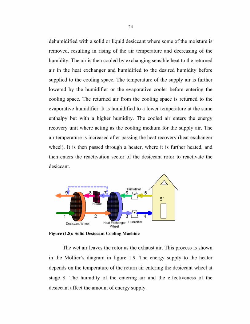
The wet air leaves the rotor as the exhaust air. This process is shown
in the Mollier’s diagram in figure 1.9. The energy supply to the heater
depends on the temperature of the return air entering the desiccant wheel at
stage 8. The humidity of the entering air and the effectiveness of the
desiccant affect the amount of energy supply.
25
The low-temperature heat can be supplied to the heater such as solar
energy from flat plate solar collector, waste heat from industry or
geothermal energy. A small amount of electricity is required for rotating
the wheels. The desiccant materials for a solid-desiccant system are usually
silica gel or Zeolite. For a liquid desiccant system, the desiccant
dehumidifier’s hygroscopic aqueous solution can be triethylene glycol
(TEG), CaCl2-H2O, LiBr-H2O, LiCl-H2O etc. The advantages and
disadvantages of the desiccant refrigeration system are shown in table 1.6.
Figure (1.9): Desiccant Cooling Process
Table (1.6): Advantages and disadvantages of the desiccant refrigeration system Advantages disadvantages Environmentally friendly because water is used as the working fluid.
Cannot get the low temperature in the humid region.
Can be integrated with a ventilation and heating system.
Required maintenance because of moving part in the rotor wheel of the solid desiccant system.
A thermal collector can be used, wich is cheaper than PV cells.
Can be contaminated easily.
Low heat release to the ambient. Difficult to design for a small application. Require dehumidifier.

26
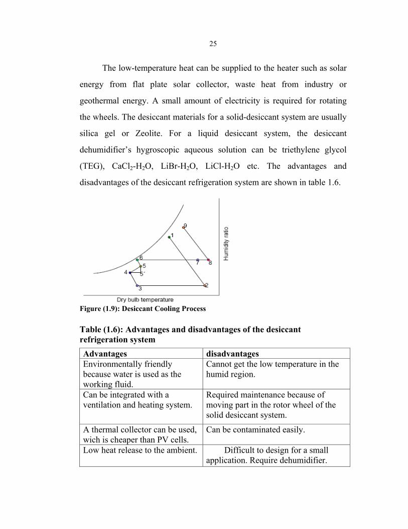
1.8.1.5. Ejector Refrigeration Cycle
An ejector refrigeration cycle is one of the heat-operating cycles Fig.
1.10. The interesting advantage is as a ‘low temperature heat supply’ air
conditioning system. With this outstanding, the research and development
of such a system has been considered increasingly since the energy crisis
1970s. Solar energy (as a renewable source) and waste heat from a heat-
operated process such as from truck engines can be integrated with the
ejector refrigeration system. The simplicity in installation, design and
operation are advantages. The pump is the only moving component in this
system. The ejector and the pump are used to maintain the pressure
differences in the system. Low efficiency is a drawback of this system,
however when the generating temperature is low, the COP of the ejector
cycle is higher than the corresponding COP of an absorption system;
moreover low-graded heat can be applied.
The major components in the solar-driven refrigeration system are an
ejector, a condenser, a generator, an evaporator, an expansion device and a
pump. The vapor from the low temperature evaporator is sucked into the
high velocity vapor stream in the ejector. The high velocity vapor stream
goes through a converging-diverging nozzle in the ejector resulting in the
vapor being sucked from the low temperature evaporator. The suction
occurs, as the pressure is low at the narrowest section of the ejector. The
stream from the evaporator reaches subsonic velocity. A mixing occurs in a
mixing zone at the end of the converging section.
27
Figure(1.10): Ejector Refrigeration Cycle
After mixing, a combined stream becomes a transient supersonic
stream, and the velocity of the combined fluid must be high enough to
increase the pressure after deceleration in the diffuser to a suitable
condensing pressure. After the pressure build-up, the stream from the
ejector goes to the condenser, condenses and heat is rejected to the
environment. After the condenser, one part of the fluid is pumped to the
generator and the rest goes to the evaporator, reaching the evaporating
pressure through the expansion device. Many refrigerants can be used with
an ejector refrigeration system such as water, R113, R114, R141b, R134a,
R11 and R12. The Advantages and disadvantages of the ejector
refrigeration system are shown at table 1.7.
28
Table (1.7): Advantages and disadvantages of the ejector refrigeration system
Advantages Disadvantages Low temperature heat source can be supplied.
Low COPs
Low operating and installation cost Difficult to achieve low evaporating temperature
Easy to design and install
Superheated is required for some refrigerant such as NH3 or water.
The system is not complex Difficult to design an ejector Required less maintenance, less interrupted service.
A large overload capacity can be achieved.
The solar collector can be used to Supply heat, which is cheaper than the Photovoltaic cells.
High reliability.
1.8.1.6. Rankin-Driven Refrigeration Cycle
A Carnot heat engine is the most efficient engine to produce work
from heat. Heat in the Carnot engine transfers from a higher temperature to
a lower temperature.
Generally, the Carnot heat engines cannot be operated since the
mechanical problems such as erosion or cavitations of turbine blades, when
operating in a two-phase region. The adaptation of the Carnot heat engine
in the one-phase region is called “Rankin" cycle. The reversible of the
Rankin heat engine is called the ‘Rankin refrigeration cycle’ or the ‘vapor
compression cycle’. Work from the turbine of the power cycle drives the
compressor of the refrigeration cycle. Any excess energy can be used to
produce electricity and reserved as a backup energy when sunshine is
lacking or it can be connected to a grid system, figure 1.11[1].
29
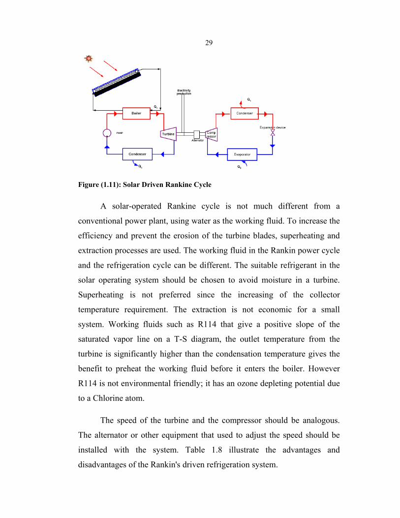
Figure (1.11): Solar Driven Rankine Cycle
A solar-operated Rankine cycle is not much different from a
conventional power plant, using water as the working fluid. To increase the
efficiency and prevent the erosion of the turbine blades, superheating and
extraction processes are used. The working fluid in the Rankin power cycle
and the refrigeration cycle can be different. The suitable refrigerant in the
solar operating system should be chosen to avoid moisture in a turbine.
Superheating is not preferred since the increasing of the collector
temperature requirement. The extraction is not economic for a small
system. Working fluids such as R114 that give a positive slope of the
saturated vapor line on a T-S diagram, the outlet temperature from the
turbine is significantly higher than the condensation temperature gives the
benefit to preheat the working fluid before it enters the boiler. However
R114 is not environmental friendly; it has an ozone depleting potential due
to a Chlorine atom.
The speed of the turbine and the compressor should be analogous.
The alternator or other equipment that used to adjust the speed should be
installed with the system. Table 1.8 illustrate the advantages and
disadvantages of the Rankin's driven refrigeration system.
30
Table (1.8): Advantages and disadvantages of the Rankin's driven refrigeration system
Advantages Disadvantages Excess energy can produce electricity.
High installation cost
Suitable for high capacity system Large system The thermal collector can be used as the heat supply, which is cheaper than PV cells.
Required maintenance because of moving parts.
Low capacity Working fluids are easy to
contaminate and are harmful for environment.
1.8.2 Electricity (Photovoltaic) Driven Systems
Vapor Compression Refrigeration Cycle
A vapor compression refrigeration system is the most widely used
cooling system because of high efficiency and reliability. Electricity, as the
main energy source, is used as the driven energy for almost vapor
compression system. Solar energy can be integrated with vapor
compression cooling system by both Photovoltaic cells and solar thermal
collectors with the Rankin engines, Figure 1.12 [1].
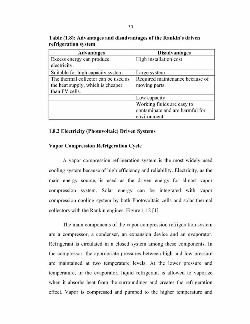
The main components of the vapor compression refrigeration system
are a compressor, a condenser, an expansion device and an evaporator.
Refrigerant is circulated in a closed system among these components. In
the compressor, the appropriate pressures between high and low pressure
are maintained at two temperature levels. At the lower pressure and
temperature, in the evaporator, liquid refrigerant is allowed to vaporize
when it absorbs heat from the surroundings and creates the refrigeration
effect. Vapor is compressed and pumped to the higher temperature and
31
pressure. The high-pressure vapor from the compressor is then condensed,
heat is transferred to the surrounding and vapor becomes the liquid
refrigerant. The liquid refrigerant goes to the evaporator passing through
the expansion device the refrigerant pressure has falling down to the
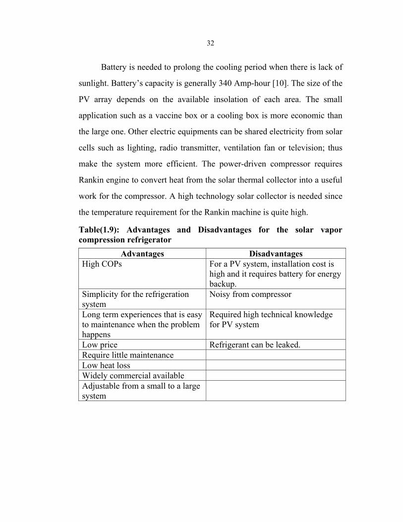
evaporator pressure. Table 1.9 shows the advantages and disadvantages for
the solar vapor compression refrigerator.
Figure(1.12): Solar-driven vapor compression refrigeration cycle
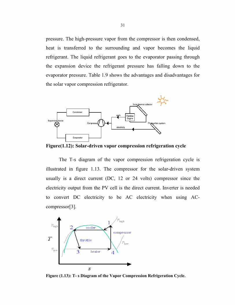
The T-s diagram of the vapor compression refrigeration cycle is
illustrated in figure 1.13. The compressor for the solar-driven system
usually is a direct current (DC, 12 or 24 volts) compressor since the
electricity output from the PV cell is the direct current. Inverter is needed
to convert DC electricity to be AC electricity when using AC-
compressor[3].
Figure (1.13): T- s Diagram of the Vapor Compression Refrigeration Cycle.
32
Battery is needed to prolong the cooling period when there is lack of
sunlight. Battery’s capacity is generally 340 Amp-hour [10]. The size of the
PV array depends on the available insolation of each area. The small
application such as a vaccine box or a cooling box is more economic than
the large one. Other electric equipments can be shared electricity from solar
cells such as lighting, radio transmitter, ventilation fan or television; thus
make the system more efficient. The power-driven compressor requires
Rankin engine to convert heat from the solar thermal collector into a useful
work for the compressor. A high technology solar collector is needed since
the temperature requirement for the Rankin machine is quite high.
Table(1.9): Advantages and Disadvantages for the solar vapor compression refrigerator
Advantages Disadvantages High COPs
For a PV system, installation cost is high and it requires battery for energy backup.
Simplicity for the refrigeration system
Noisy from compressor
Long term experiences that is easy to maintenance when the problem happens
Required high technical knowledge for PV system
Low price Refrigerant can be leaked. Require little maintenance Low heat loss Widely commercial available Adjustable from a small to a large system
33
Chapter Two Solar Adsorption Refrigeration
2.1 History and Advantages
In the early years of the previous century, sorption (adsorption)
refrigeration was frequently used, later with the development of cheap
reliable compressors and electrical motors, the improvement in power
station efficiency and the introduction of CFCs in the 1930s, sorption
refrigeration became a niche technology [11].
Heat-driven sorption refrigeration cycles have existed in patent
literature since at least 1909, and refrigerators were commercially available
in the 1920s. In 1929, Miller described several systems, which utilized
silica gel and sulfur dioxide as an adsorbent/adsorbate pair [12]. However,
recent years have witnessed increasing interest in this technology for many
different reasons. The main arguments in favor are that sorption systems
are quiet, long lasting, cheap to maintain and environmentally benign.
Refrigeration technology is required to evolve due to the new
environmental regulation. The first regulation concerning the depletion of
the ozone layer (Montreal protocol, 1988) [13], decided to phase-out
chlorofluorocarbons (CFCs) and then hydro chlorofluorocarbons (HCFCs).
More recently adsorptive processes have been proposed for heat pump and
refrigeration as consistent alternative to vapor compression systems.
Ecological problems concerning the emission of CFCs from refrigerating
units have stimulated several theoretical and experimental studies on
adsorption cooling systems. The environmental impact of fluorocarbon
34
traces in the atmosphere has shown that CFC emissions are responsible for
about one-third the global greenhouse effect [14].
These trends bring to a strong exigency of new systems for space
heating and cooling, with the possibility also to obtain a primary energy
diversification. Among the proposed technologies, the solid sorption has a
very good perspective, in fact, in addition to the non-polluting refrigerants,
they can efficiently use natural gas or solar energy as primary energy and
they have no moving parts, which makes the machine silent and with no
maintenance needs. Therefore, adsorption heating and cooling can be a
good alternative to classical vapor-compression machines. Adsorption
cooling units are attractive since they can be operated at temperature levels
where liquid absorption systems cannot work.
Adsorption is accompanied by evolution of heat. Also, the heat of
adsorption is usually 30–100% higher than that of condensation of the
adsorbate. Thus, if a fresh adsorbent and adsorbate in liquid form coexist
separately in a closed vessel, transport of adsorbate from the liquid phase to
the adsorbent occurs in the form of vapor, since adsorption is stronger than
condensation to liquid phase. During this step, the temperature of the liquid
phase becomes lower while the adsorbent temperature rises. Air-
conditioning and refrigeration utilize this phenomenon [15]. Solid/gas
systems present the advantage of being absolutely benign for the
environment: zero ODP (ozone depletion potential) as well as zero GWP
(global warming potential). However, to become a realistic alternative,
those systems must exhibit high enough performances to avoid extra
primary energy consumption. The figures of merit which are commonly
35
used to characterize the performances of such cycles are the COP
(coefficient of performance), the SCP (specific cooling power) and the
thermodynamic efficiency, which is the ratio between the COP and the
Carnot COP. The use of solids for removing substances from either
gaseous or liquid solutions has been widely used since biblical times. This
process, known as adsorption, involves nothing more than the preferential
partitioning of substances from the gaseous or liquid phase onto the surface
of a solid substrate. From the early days of using bone char for
depolarization of sugar solutions and other foods, to the later
implementation of activated carbon (AC) for removing nerve gases from
the battlefield, to today’s thousands of applications, the adsorption
phenomenon has become a useful tool for purification and separation[ 13 ].
2.2 System Description
One of the very effective forms of solar refrigeration is the
production of ice, since ice accumulates much latent heat in it. The most
promising application to produce ice by using solar energy is the solid
adsorption refrigeration, due to its simple operation and its ability to utilize
low grade thermal energy. Although different adsorption pairs had been
studied to build adapted solar ice maker. The activated carbon–methanol
pair was found the most suitable for solar-powered refrigeration since it
could be driven by heat of relatively low, near ambient temperatures. Also
it is less expensive than other pairs [16,17]. The adsorption solar
refrigerator in its simplest form is a closed system composed of the
container of adsorbents and adsorbate (sorption bed), which serves as a
solar collector, a condenser and an evaporator. The cycle of this system is
36
divided into two periods: First, the adsorbent is heated by solar energy
during the day and the desorbed adsorbate is condensed. Then the
adsorbent is cooled after sunset, thereby re-adsorbing the adsorbate, the
evaporation of which produces the refrigeration effect. As desorption is
highly endothermic, the heat input to the adsorber must be large enough to
allow for sufficient refrigerant to be desorped. On the other hand,
adsorption is highly exothermal, so, cooling down of the adsorber is also a
major concern. Although, the alternation of heating and cooling during the
cycle perfectly suits the intermittent nature of solar energy, yet efficient
operation of the system requires high rates of heat transfer in and out of the
adsorbent. Unfortunately, some problems are encountered which affect
rates of heat transfer. First, the heat transfer of adsorbent bed is very poor,
due to low convective heat transfer to the adsorber and bad thermal
conductivity of the adsorbent. Second, the thermal mass of the container
presented an unacceptably high thermal load which affected alternation of
heating and cooling. Third, the system suffers from the problem of being
tightly sealed against air leakage through the joints and valves which
results in degrading the cooling performance. In addition, all solar systems
usually suffer from the large variations in ambient conditions between
winter and summer, which makes these systems inefficient for part of the
year. In solar adsorption systems, while good heating is attained during day
time in summer, cooling during night by ambient air will be limited. On the
other hand, in winter, the system will attain good cooling during the night,
but heating will be insufficient. In the last two decades, different
approaches have been developed to improve heat transfer rates and enhance
heating and cooling of the adsorbent bed. The use of composite adsorbent
37
blocks and monolithic carbon are useful methods to increase both thermal
conductivity and density of the bed [18]. To enhance heating of the beds,
flat plate solar collectors with selective surfaces, evacuated tubular
collectors and simple concentration non-tracking collectors as compound
parabolic concentrator collector have been used. As cooling of the
adsorbent is by rejecting heat to the environment, heat loss from the
collector to the ambient could be enhanced by means of removable
insulation, flaps, or dampers [19]. Some designs combine the collector and
finned condenser at one unit since outside fins have been located on the
rear surface of the collector [20]. By day the solar collector is a desorber
and a condenser. At night, the condenser cools the collector. Therefore the
investigations must be focused to improve heat transfer in the adsorbent
bed, thereby increasing COP, and to improve external heating and cooling
of the bed all year round, thereby realizing good performance of the system
for most times of the year.
2.3 Principle of Adsorption
Adsorption is a solid sorption process where the binding forces
between fluid molecules and the solid medium come from an electrostatic
origin or from dispersion - repulsion forces (Van der Waals forces). It is an
exothermic process due to the gas-liquid phase change. The energy
liberated in adsorption is called isosteric heat, and it depends on the nature
of the adsorbent - adsorbate pair.
To describe the thermodynamic equilibrium of adsorption, several
state equations known as isotherms of adsorption are proposed. These
functions correlate the temperature T, the pressure P, and the concentration
38
of the adsorbed phase a , so that f (T, P, a) = 0, [21]. The main isotherms of
adsorption are: (a) Henry's law, valid for weak concentrations; (b)
Langmuir's approach, which considers adsorption in monomolecular layers
and that there is a dynamic equilibrium between the phases; (c) Gibbs'
theory, based on the perfect gas equation, in which the adsorbate is treated
in microscopic and bidimensional form; and (d) Adsorption Potential
theory, based on a model originally proposed by Polany by the end of the
20s, which is a purely thermodynamic approach, suitable for adsorption in
micro porous materials. A detailed analysis of the thermodynamics of
adsorption and its different isotherms is given by [22].
All micro porous materials are generally adsorbent media,
characterized by high porosity. Their structures have pores with diameters
smaller than 20A . The most commonly utilized adsorbents are silica gel,
activated carbon, alumines and zeolites. Zeolite-water and activated
carbon- methanol are the most used adsorbent-adsorbate pairs in
refrigeration systems. These two pairs have entirely different physical and
chemical properties: methanol is easily desorbed from activated carbon
when it is heated, while in zeolite, the water is kept much longer. Thus, the
activated carbon methanol pair is best adapted to operating cycles with
small evaporating temperature variation (up to 40 οC), since adsorption
cycles with the Zeolite+water pair need a larger evaporating temperature
change (70 οC or more) to operate, [23].
For the equilibrium of adsorption in micro porous materials with a
polymodal distribution of pore dimensions, such as the activated carbon-
methanol pair, Dubinin and Astakhov [24] proposed the following
isotherm:
39
a = W0ρ1(T) exp{-D[ T ln( p /Ps ) ] n} (2.1)
where ,a , is the adsorbed mass per unit of adsorbent mass, W0 the
maximum adsorption capacity (volume of adsorbate/mass of adsorbent), ρ1
the specific mass of the adsorbate in the liquid state, D the coefficient of
affinity'' and n is a characteristic parameter of the adsorbent/adsorbate pair.
This equation has a wide field of application, and it is particularly
appropriate strongly for activated carbon with a large pores
heterogeneousness. According to [21], a fitted curve obtained from
experimental results of methanol adsorption in activated carbon presented a
residual error of 2.2%, related to the characteristic function proposed by
Dubinin and Astakhov. These experiments were performed within a
temperature range between 20 and 100 οC and for an adsorbed mass
ranging from 71 to 286 g/kg of adsorbent. For smaller temperatures, the
residual error was lower than 2%. These results indicate that this state
equation is possibly adequate for many engineering applications of low
grade heat, especially those concerning solar energy [21].
2.4 Selection of Adsorbent / Adsorbate Pair
At present, three types of working adsorate and adsorbent,
respectively, are favored for pairing for use in solid adsorption solar
refrigeration technology: Ammonia, Methanol and Water for adsorbate and
activated carbon, silica-gel and zeolite for the adsorbent. The selection of
any pair of adsorbent/adsorbate depends on certain desirable characteristics
of their constituents, including the affinity for each other. These
characteristics range from their thermodynamic and chemical properties to
their physical properties and even to their costs or availability.
40
For refrigerating applications, "the adsorbent must have high adsorptive
capacity at ambient temperature and low pressures and a small capacity of
adsorption at high temperatures and pressures". The cooling effect, or the
temperature attained in the evaporator, depends on the adsorptive capacity
at small pressures. This is the property that allows the adsorbent, at a given
temperature, to retain vapors from a fluid at a lower temperature. On the
other hand, the more intense this property is, the higher the adsorbent
regenerating temperature is. Thus, choosing the adsorbent will depend on
two basic factors:
• The temperature at which the evaporator must operate;
• The regenerating temperature that the thermal source can possibly attain.
Another important aspect in choosing the adsorbent is the possible
catalysis of the adsorbate's dissociating reactions. For example, the
methanol adsorption in zeolite is restricted to 100 οC as its maximum
temperature. At higher values, the zeolite is a catalyst for the methanol,
water and dimethyl ether reaction, producing a blockage of the adsorption
process [11]. For the activated carbon-methanol pair, this catalyst reaction
will only occur above 150 οC, which is perfectly suitable for solar
refrigeration applications. Thus we can summarize the considerations
influencing the choice of a suitable adsorbent as follows :
• Porous materials that should adsorb a large amounts of the adsorbate
under low temperature conditions to yield good COP.
• Desorption of most of the adsorbate when exposed to thermal energy.
41
• Possession of high latent heat of adsorption compared to its sensible
heating load.
• No deterioration with age or use, thus it is reversibility of adsorption
process for many cycles.
• Non-toxic and non-corrosive.
• Low cost and widely available.
• Wide concentration change in a small temperature range.���
• Good thermal conductivity.
The choice of the adsorbate, or the working fluid, shall depend on
the main conditions:
• The evaporator temperature, according to the application;
• The latent heat of evaporation, which should be high;
• The molecular dimensions, which should be small enough to allow easy
adsorption.
• Thermally stable with the adsorbent at the cycle operating temperature
ranges.
• Non-toxic, non-corrosive and non-flammable.
• Low saturation pressures (slightly above atmospheric) at normal
operating temperature.
42
A survey of the favored working adsorbates shows that methanol and
water operate at subatmospheric saturation pressures at the operating
temperatures needed, and an ingress of air immediately results in system
malfunction. Ammonia does not have this problem because its outward
leak could be tolerated for some time, but its saturation pressure of 13 bar
at 35 οC condensing temperature is quite high. In the case of methanol, with
a normal boiling point of 65 οC, the low saturation pressures could be
exploited advantageously to detect leakages, since it must necessarily result
in abnormal increases in system pressure and poor performances.
Ammonia, methanol and water, all have relatively high latent heat
values of 1368, 1102 and 2258 kJ/kg, respectively, and their specific
volumes are low, on the order of about 10-3 m3/kg [25].
Ammonia is toxic and corrosive, while water and methanol are not,
but the problem with alcohols is that they are flammable. Water is the most
thermally stable with adsorbents, closely followed by methanol and
ammonia in that order. However, water cannot be used for freezing
purposes because its freezing temperature is 0 οC. This makes methanol a
favored adsorbate for pairing with a stable adsorbent.
Various kinds of working pairs for adsorption refrigeration have
been already studied, and they include both physical and chemical
adsorption working pairs. The main physical adsorbents are activated
carbon, zeolite, and silica gel, and accordingly, the physical adsorption
working pairs are mainly activated carbon–methanol, activated carbon–
ammonia, zeolite–water and silica gel–water. In recent years, the working
43
pairs activated carbon–HFC-134a, and activated carbon–dimethylether
were also investigated [26].
As water is the refrigerant normally used with zeolite or silica gel,
the evaporating temperature is never lower than 0oC. Compared to other
physical adsorption working pairs, the main advantage of the utilization of
activated carbon as adsorbent is the low evaporating temperature that can
be reached, as the refrigerants most employed are ammonia or methanol.
Due to the low evaporation temperature of these refrigerants, these pairs
are more suitable for ice making technology.
Chemical adsorbents mainly include metal chlorides and metal
hydrides. The metal chlorides generally use ammonia as refrigerant when
designed for ice making purposes. The main advantage of the metal
chlorides working pairs is the larger adsorption quantities, which are about
5–6 times of that obtained with the physical adsorption working pairs.
The disadvantages of metal chlorides are the phenomena of swelling
and agglomeration when the expansion space for the salt is, respectively,
too large or too small. The swelling phenomenon reduces the heat transfer
performance, and the agglomeration phenomenon reduces the mass transfer
performance. In order to improve the heat and mass transfer of metal
chlorides, composite adsorbents using graphite or carbon fiber as porous
additives were researched. Various studies have developed detailed models
and examined the suitability of various adsorbent/adsorbate pairs for solar
cooling applications [26]. Differential heats of adsorption for some
adsorbent/adsorbate pairs are given at Table 2.1[13].
44
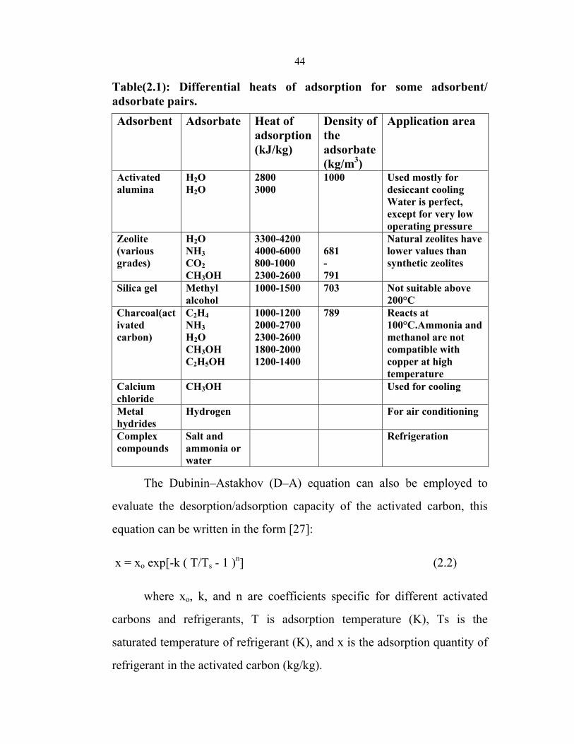
Table(2.1): Differential heats of adsorption for some adsorbent/ adsorbate pairs.
Application area Density of the adsorbate(kg/m3)
Heat of adsorption (kJ/kg)
Adsorbate Adsorbent
Used mostly for desiccant cooling Water is perfect, except for very low operating pressure
1000 2800 3000
H2O H2O
Activated alumina
Natural zeolites have lower values than synthetic zeolites
681 - 791
3300-4200 4000-6000 800-1000 2300-2600
H2O NH3 CO2 CH3OH
Zeolite (various grades)
Not suitable above 200°C
703
1000-1500 Methyl alcohol
Silica gel
Reacts at 100°C.Ammonia and methanol are not compatible with copper at high temperature
789 1000-1200 2000-2700 2300-2600 1800-2000 1200-1400
C2H4 NH3 H2O CH3OH C2H5OH
Charcoal(activated carbon)
Used for cooling CH3OH Calcium chloride
For air conditioning Hydrogen Metal hydrides
Refrigeration Salt and ammonia or water
Complex compounds
The Dubinin–Astakhov (D–A) equation can also be employed to
evaluate the desorption/adsorption capacity of the activated carbon, this
equation can be written in the form [27]:
x = xo exp[-k ( T/Ts - 1 )n] (2.2)
where xo, k, and n are coefficients specific for different activated
carbons and refrigerants, T is adsorption temperature (K), Ts is the
saturated temperature of refrigerant (K), and x is the adsorption quantity of
refrigerant in the activated carbon (kg/kg).
45
Adsorption properties of activated carbon–methanol were tested [27]
, and the coefficients of D–A equations are: xo= 0.45; k =13.38; n = 1.5
The adsorption properties of activated carbon–methanol were
calculated by Eq. (2.2) at different evaporation temperatures, ranging from
-20 to 35 οC, while the adsorption properties of activated carbon–ammonia
were xo = 0.29; K =3.57; n = 1.38 [27].
The cooling quantity is the product of latent heat and the adsorption
quantity. The values of latent heat for ammonia and methanol are similar.
For example, at the evaporating temperature of -30 οC, the latent heat of
ammonia is 1365 kJ/(kg οC), which is only 5% larger than the value of
methanol that is 1299.1 kJ/(kg οC). The adsorption quantity of activated
carbon–methanol is 59% larger than that of activated carbon–ammonia,
which means that the adsorption performance of activated carbon–
methanol is better than that of activated carbon–ammonia [27].
The temperature lift capabilities of adsorbent/adsorbate pairs [25],
which are adsorption– evaporation and generation–condensation
temperatures, have been used as the basis for their selection. Meunier,[28 ]
comparing activated carbon/methanol (AC 35/CH3OH) and zeolite
13X/water (NaX/H2O) using their isosters and typical refrigeration cycles
(see Fig. 2.1), reports that the AC- 35/CH3OH adsorption evaporation
temperature lift has to be limited to 40 oC and low generating temperatures
(<150 oC), whereas for NaX/H2O the corresponding temperature lift may be
up to 70 oC, or even more, with very high generating temperatures (250–
300 oC).
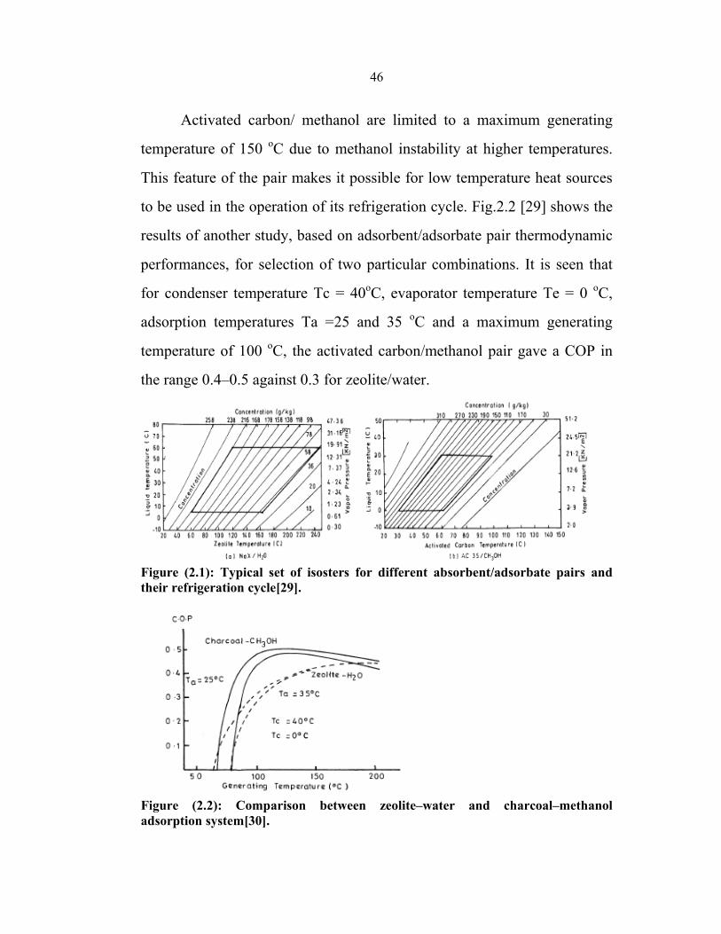
46
Activated carbon/ methanol are limited to a maximum generating
temperature of 150 oC due to methanol instability at higher temperatures.
This feature of the pair makes it possible for low temperature heat sources
to be used in the operation of its refrigeration cycle. Fig.2.2 [29] shows the
results of another study, based on adsorbent/adsorbate pair thermodynamic
performances, for selection of two particular combinations. It is seen that
for condenser temperature Tc = 40oC, evaporator temperature Te = 0 oC,
adsorption temperatures Ta =25 and 35 oC and a maximum generating
temperature of 100 oC, the activated carbon/methanol pair gave a COP in
the range 0.4–0.5 against 0.3 for zeolite/water.
Figure (2.1): Typical set of isosters for different absorbent/adsorbate pairs and their refrigeration cycle[29].
Figure (2.2): Comparison between zeolite–water and charcoal–methanol adsorption system[30].
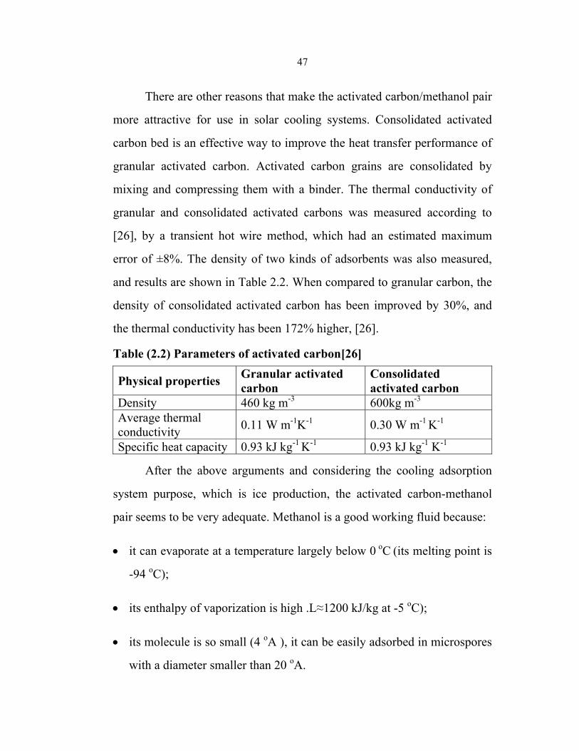
47
There are other reasons that make the activated carbon/methanol pair
more attractive for use in solar cooling systems. Consolidated activated
carbon bed is an effective way to improve the heat transfer performance of
granular activated carbon. Activated carbon grains are consolidated by
mixing and compressing them with a binder. The thermal conductivity of
granular and consolidated activated carbons was measured according to
[26], by a transient hot wire method, which had an estimated maximum
error of ±8%. The density of two kinds of adsorbents was also measured,
and results are shown in Table 2.2. When compared to granular carbon, the
density of consolidated activated carbon has been improved by 30%, and
the thermal conductivity has been 172% higher, [26].
Table (2.2) Parameters of activated carbon[26] Consolidated activated carbon
Granular activated carbonPhysical properties
600kg m-3 460 kg m-3Density
0.30 W m-1 K-1 0.11 W m-1K-1 Average thermal conductivity
0.93 kJ kg-1 K-10.93 kJ kg-1 K-1Specific heat capacity
After the above arguments and considering the cooling adsorption
system purpose, which is ice production, the activated carbon-methanol
pair seems to be very adequate. Methanol is a good working fluid because:
• it can evaporate at a temperature largely below 0 οC (its melting point is
-94 οC);
• its enthalpy of vaporization is high .L≈1200 kJ/kg at -5 οC);
• its molecule is so small (4 οA ), it can be easily adsorbed in microspores
with a diameter smaller than 20 οA.
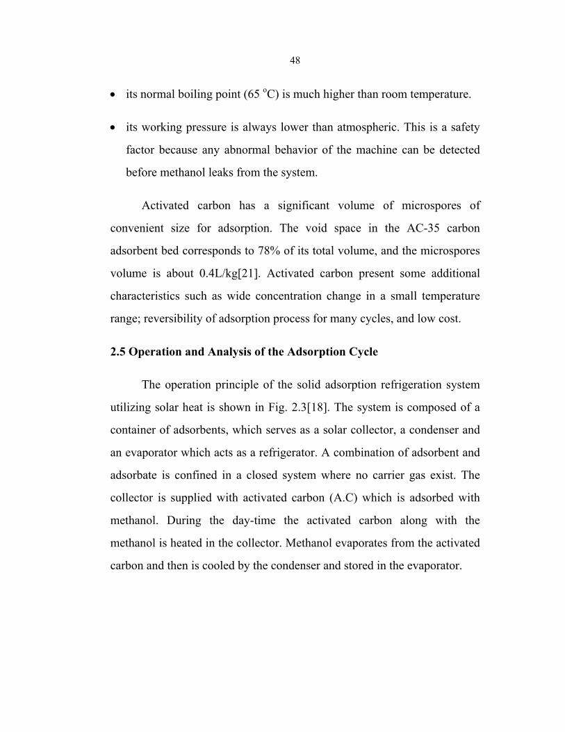
48
• its normal boiling point (65 οC) is much higher than room temperature.
• its working pressure is always lower than atmospheric. This is a safety
factor because any abnormal behavior of the machine can be detected
before methanol leaks from the system.
Activated carbon has a significant volume of microspores of
convenient size for adsorption. The void space in the AC-35 carbon
adsorbent bed corresponds to 78% of its total volume, and the microspores
volume is about 0.4L/kg[21]. Activated carbon present some additional
characteristics such as wide concentration change in a small temperature
range; reversibility of adsorption process for many cycles, and low cost.
2.5 Operation and Analysis of the Adsorption Cycle
The operation principle of the solid adsorption refrigeration system
utilizing solar heat is shown in Fig. 2.3[18]. The system is composed of a
container of adsorbents, which serves as a solar collector, a condenser and
an evaporator which acts as a refrigerator. A combination of adsorbent and
adsorbate is confined in a closed system where no carrier gas exist. The
collector is supplied with activated carbon (A.C) which is adsorbed with
methanol. During the day-time the activated carbon along with the
methanol is heated in the collector. Methanol evaporates from the activated
carbon and then is cooled by the condenser and stored in the evaporator.
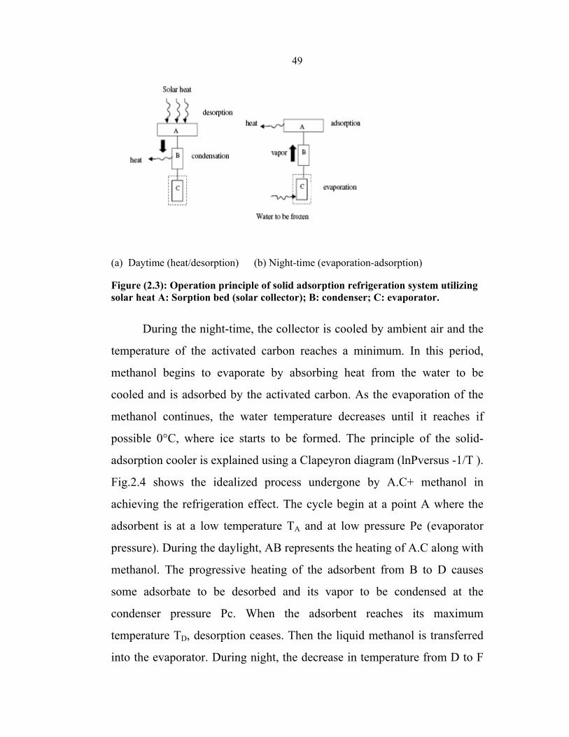
49
(a) Daytime (heat/desorption) (b) Night-time (evaporation-adsorption)
Figure (2.3): Operation principle of solid adsorption refrigeration system utilizing solar heat A: Sorption bed (solar collector); B: condenser; C: evaporator.
During the night-time, the collector is cooled by ambient air and the
temperature of the activated carbon reaches a minimum. In this period,
methanol begins to evaporate by absorbing heat from the water to be
cooled and is adsorbed by the activated carbon. As the evaporation of the
methanol continues, the water temperature decreases until it reaches if
possible 0°C, where ice starts to be formed. The principle of the solid-
adsorption cooler is explained using a Clapeyron diagram (lnPversus -1/T ).
Fig.2.4 shows the idealized process undergone by A.C+ methanol in
achieving the refrigeration effect. The cycle begin at a point A where the
adsorbent is at a low temperature TA and at low pressure Pe (evaporator
pressure). During the daylight, AB represents the heating of A.C along with
methanol. The progressive heating of the adsorbent from B to D causes
some adsorbate to be desorbed and its vapor to be condensed at the
condenser pressure Pc. When the adsorbent reaches its maximum
temperature TD, desorption ceases. Then the liquid methanol is transferred
into the evaporator. During night, the decrease in temperature from D to F
50
induces the decrease in pressure from Pc to Pe. Then the adsorption and
evaporation occur while the adsorbent is cooled from F to A. During this
cooling period heat is withdrawn both to decrease the temperature of the
adsorbent and to withdraw adsorption heat [18].
Figure(2.4): Clapeyron diagram (ln P versus -1/T ) of ideal adsorption cycle.[18]
From the Clapeyron diagram, the total energy gained by the system
during the heating period QT will be the sum of the energy QAB used to
raise the temperature of the A.C+ methanol from point A to B and the
energy QBD used for progressive heating of the A.C to point D and
desorption of methanol:
QT = QAB + QBD (2.3) QAB = (mA.C CpAC+
Cpm mmA)( TB – TA ) (2.4)
QBD =[ mA.CCpA.C +Cpm{(mmA +mmD) / 2}](TD – TB)+(mmA-mmD) H (2.5)
Where ; mA.C : mass of activated carbon (kg) , CpA.C : specific heat of A.C
(kJ/kgK)
mm , Cpm : mass and specific heat of methanol respectively .
51
H: heat of desorption, kJ/kg.
The gross heat released during the cooling period Qe1 will be the energy of
vaporization of methanol.
Qel = ( mmA - mmD ) L (2.6)
Where; L is the Latent heat of evaporation of methanol, kJ/kg.
But the net energy actually used to cool water Qe will be
Qe = Qe1 – Qe2 (2.7)
where Qe2 is the energy necessary for cooling the liquid adsorbate from the
temperature at which it is condensed to the temperature at which it
evaporates.
Qe2 = ( mmA – mmD )Cpm( Tc – Te ) (2.8)
If we obtained ice :
Qice is the energy required to cool water from TA to 0 °C and to produce ice
Qice = Mice ( Lice + Cpwater(TA – 0 ) (2.9)
where Mice, and Lice are the mass and latent heat of fusion of ice
respectively, [18].
2.6 Coefficient of performance (COP)
The ideal cycle for an adsorption cooling system corresponds to a
hypothetical quadrithermal machine. This device consists of two coupled
machines operating at two temperature levels without mechanical energy
conversion. The Carnot's COP of a quadrithermal machine can be given by:
52
COP = desired output / required input
=Qe / Qgen (2.10)
The maximum COP of an adsorption refrigeration system is
determined by assuming that the entire cycle is totally reversible. The
refrigeration system would be reversible if the heat from the source ( Qreg)
were transferred to a Carnot heat engine, and the work output of this heat
engine ( W = ηth Qgen) is supplied to a Carnot refrigerator to remove heat
from the refrigerated space.
Note that Qe= W . COPR,C = ηth,C . Qgen . COPR,C . Then the overall COP of
an adsorption refrigeration system under reversible conditions becomes:
COPP ,rev = Qe / Qgen = ηth,c COPR,C = (1- ) ( ) (2.11)
where Tev, Tcon and Treg are the evaporation, condensation and
regeneration temperatures, respectively. T0 is a reference temperature,
above the ambient temperature, considered to be the highest adsorption
temperature possible [4,21].
A thermodynamic analysis, given by Leite [22], demonstrates that
Carnot's COP can be approximately written as:
COP ≈ Tcon /Treg (2.12)
Solar COP ( COPSolar) is one of the parameters currently used to
evaluate the performance of solar ice makers, and defined as the ratio of the
total heat extracted by evaporation of the desorbed mass of themethanol
(kJ) to the total incident global irradiance ∫ i(t)dt from sunrise to sunset :
53
COPsolar = ( Qref – Qcc ) / ∫ i(t)dt ( 2. 13 )
Where; i(t) : intensity of solar radiation W/ m2
Qref: refrigeration effect
Qcc: the energy used to cool down the refrigerant liquid from condensing
temperature Tc to evaporation temperature Te.
As it can be deduced from the analysis of the above equation, the
COPsolar depends on both the meteorological conditions and the efficiency
of each main component of the system i.e. the solar collector, the condenser
and the evaporator.
As the desorbed mass mdes is the difference between the
concentration of adsorbate in the adsorbent at the beginning and at the end
of the desorption phase: mdes= xconc- xdil.
With a sufficient insolation, the concentration xdilwill be in
proportion lower if the adsorbent heating and the vapor condensation
simultaneously occur efficiently. On the other hand, xconc depends on the
initial concentration of the methanol in the adsorbent which, with a
favorable ambient temperature, will be in proportion higher if the adsorbent
cooling and the liquid evaporation, during the previous cycle,
simultaneously occurred efficiently. Then the COPsolar appears to be an
important parameter which has to be taken into account, when comparing
different adsorptive solar refrigeration systems. Up to now, the COPsolar of
all experimented adsorption solar refrigerator systems rarely exceeded 0.2,
but it is of little importance since solar energy is free [30].
54
2.7 The Effects of Collector and Environment Parameters on the
Performance of a Solar Powered Adsorption Refrigerator
The characteristics of solar cooler are affected by many parameters.
Generally speaking, we can divide these parameters into two types. One
type is the parametric parameters, such as dimensions, material and
characteristics of collector, which decides the physical property of
collector. Another type of parameters is environmental parameters, such as
radiation intensity, ambient temperature and wind speed, which affect the
running quality of system performance.
2.7.1. Parametric Effects
As mentioned above, the characteristics of solar refrigerator are
mainly decided by adsorbent bed (collector), so the property of the each
collector part determines the behavior of the solar refrigerator in practical
application. The solar collector design parameters of interest are the
collector plate material and emissivity, the size of housing adsorbent, fins
for heat transfer, material, number of glazing, the thermal conductivity,
packing density of the adsorbent granules. The performance of solar
refrigerator is mainly decided by the total condensed refrigerant, the cooled
water, the produced ice mass if possible as well as the useful coefficient of
performance (COP). The latter is defined as the total useful cooling divided
by the total incident radiation. In the processes of analyzing parametric
effects on the solar refrigerator, the environmental conditions assumed
remain constant [31].
55
a- Effect of Heat transfer Fins
Because the thermal conductivity of the adsorbent is low, using fins
to improve heat transfer is very important inside the collector adsorbent.
Theoretically speaking, increasing the number of fins will improve
heat transfer, but it is obvious that the presence of these fins also has
negative effects, because the sensible heat of the fins will be
thermodynamically useless. So there is an optimization value about the fin
numbers.
b- Effects of the Contact Thermal Resistance
The contact thermal resistance is a key parameter which affects the
characteristics of solar refrigerator. The adsorbent is installed usually inside
definite shape of metal, the metal accepts the solar radiation energy to heat
adsorbent to release refrigerant. Due to the existence of thermal contact
resistance between adsorbent and metal surface, this will lead a big
temperature gradient and reduce the heat transfer effect from metal surface
to adsorbent. Usually, the bigger the contact thermal resistance between
metal surface and adsorbent, the inferior is the characteristics of solar
refrigerator. Therefore, in order to reduce this contact thermal resistance, a
well suited shape of the solid bed with a smooth surface should be taken
into consideration carefully.
c- Effects of Adsorbent Thermal Conductivity
Nearly all suitable adsorbents are porous materials that can adsorb a
large amount of refrigerant, while the thermal conductivity of the adsorbent
is very low, this makes limiting factor to performance of solar cooler. For
56
flat plate solar refrigerator, activated carbon is usually chosen as adsorbent,
and the thermal conductivity values of adsorbent are usually less than 1.0
W m-1 K-1.
So it is very useful to pay attention to improve the heat transfer in
adsorbent bed. In order to improve the adsorbent conductivity, many
methods have been adopted [32].
For example, metallic spheres or strips can be incorporated into the
bed, or good thermal conductivity material or metallic foam can be used to
the absorbent, and consolidated samples (like bricks) is used. But so far,
there are no practical application used in solar refrigerator.
The main reason is the energy density accepted by solar refrigerator
is very low, this limits the application of the above mentioned methods.
e- Effect of Number of Glazing and Selective Coating
Besides the above mentioned parameters, there are many other
parameters that affect the performance of solar refrigerator and ice mass,
such as numbers of glass cover, coating material etc. Among these
parameters, two parameters are most important; they are the number of
glazing and the selective coating material. Usually, the increase of glazing
number is limited by collector structure and dimension; in common
practice, not more than two or three glazing. In summary, many parameters
affect the characteristics of solar refrigerator. From the view of
optimization of design, we should choose the best parameter to build the
collector under the suitable cost.
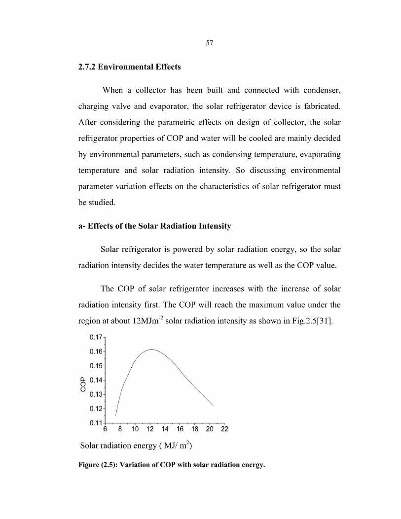
57
2.7.2 Environmental Effects
When a collector has been built and connected with condenser,
charging valve and evaporator, the solar refrigerator device is fabricated.
After considering the parametric effects on design of collector, the solar
refrigerator properties of COP and water will be cooled are mainly decided
by environmental parameters, such as condensing temperature, evaporating
temperature and solar radiation intensity. So discussing environmental
parameter variation effects on the characteristics of solar refrigerator must
be studied.
a- Effects of the Solar Radiation Intensity
Solar refrigerator is powered by solar radiation energy, so the solar
radiation intensity decides the water temperature as well as the COP value.
The COP of solar refrigerator increases with the increase of solar
radiation intensity first. The COP will reach the maximum value under the
region at about 12MJm-2 solar radiation intensity as shown in Fig.2.5[31].
Solar radiation energy ( MJ/ m2) Figure (2.5): Variation of COP with solar radiation energy.
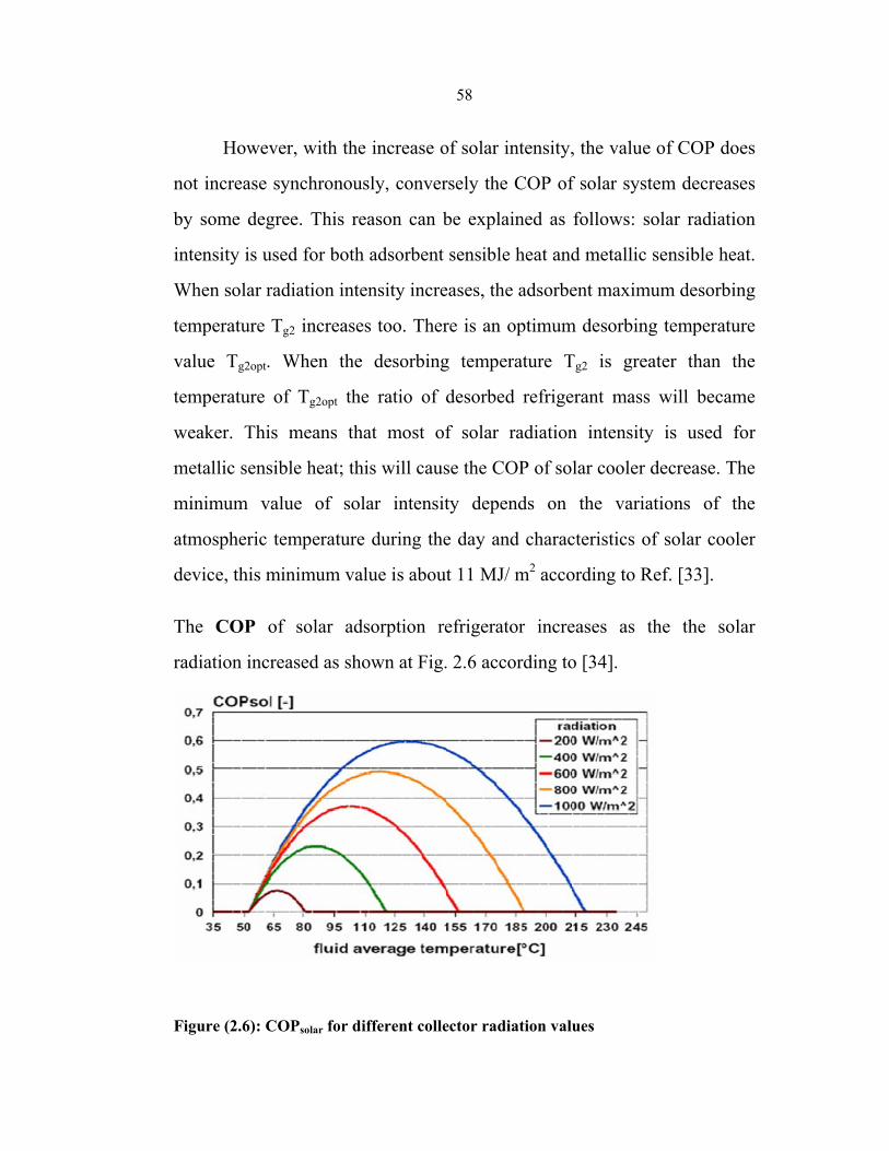
58
However, with the increase of solar intensity, the value of COP does
not increase synchronously, conversely the COP of solar system decreases
by some degree. This reason can be explained as follows: solar radiation
intensity is used for both adsorbent sensible heat and metallic sensible heat.
When solar radiation intensity increases, the adsorbent maximum desorbing
temperature Tg2 increases too. There is an optimum desorbing temperature
value Tg2opt. When the desorbing temperature Tg2 is greater than the
temperature of Tg2opt the ratio of desorbed refrigerant mass will became
weaker. This means that most of solar radiation intensity is used for
metallic sensible heat; this will cause the COP of solar cooler decrease. The
minimum value of solar intensity depends on the variations of the
atmospheric temperature during the day and characteristics of solar cooler
device, this minimum value is about 11 MJ/ m2 according to Ref. [33].
The COP of solar adsorption refrigerator increases as the the solar
radiation increased as shown at Fig. 2.6 according to [34].
Figure (2.6): COPsolar for different collector radiation values
59
b- Effects of the Condensing Temperature
The performance of solar refrigerator is affected obviously by
condensing temperature. In order to keep condensing temperature in a
lower level, it is an effective way that adopting water to cool condenser
instead of natural convection cooling. With the water cooling method, solar
refrigerator can be worked in a suitable environmental condition, and the
performance of solar system can be improved efficiently.
c- Effects of the Evaporating Temperature
The use of refrigerant other than water makes it possible that
evaporating temperature is below 0°C. Usually, for solar refrigerator, the
lower the evaporating temperature is, the poor the performance is. For solar
refrigerator, because the energy of solar radiation is limited by weather
condition, the evaporating temperature is in the range of -10°C≤Te≤0°C. If
evaporating temperature is above 0°C, zeolite–water working pair can be
used, this will cause a good refrigeration effect because the latent heat of
water is larger than that of methanol.
From the previous discussion, significant improvements in the solar
refrigerator performance can be obtained through a careful choice of a
number of collector parameters. Generally speaking, enhancing the heat
transfer between metallic plate and adsorbent, increasing the thermal
conductivity of adsorbent are two obvious methods for improving
performance of solar refrigerator. Increasing packing density of adsorbent,
adopting double glass covers, using selective coating material as well as
using heat transfer fins, all these ways are beneficial to increase properties
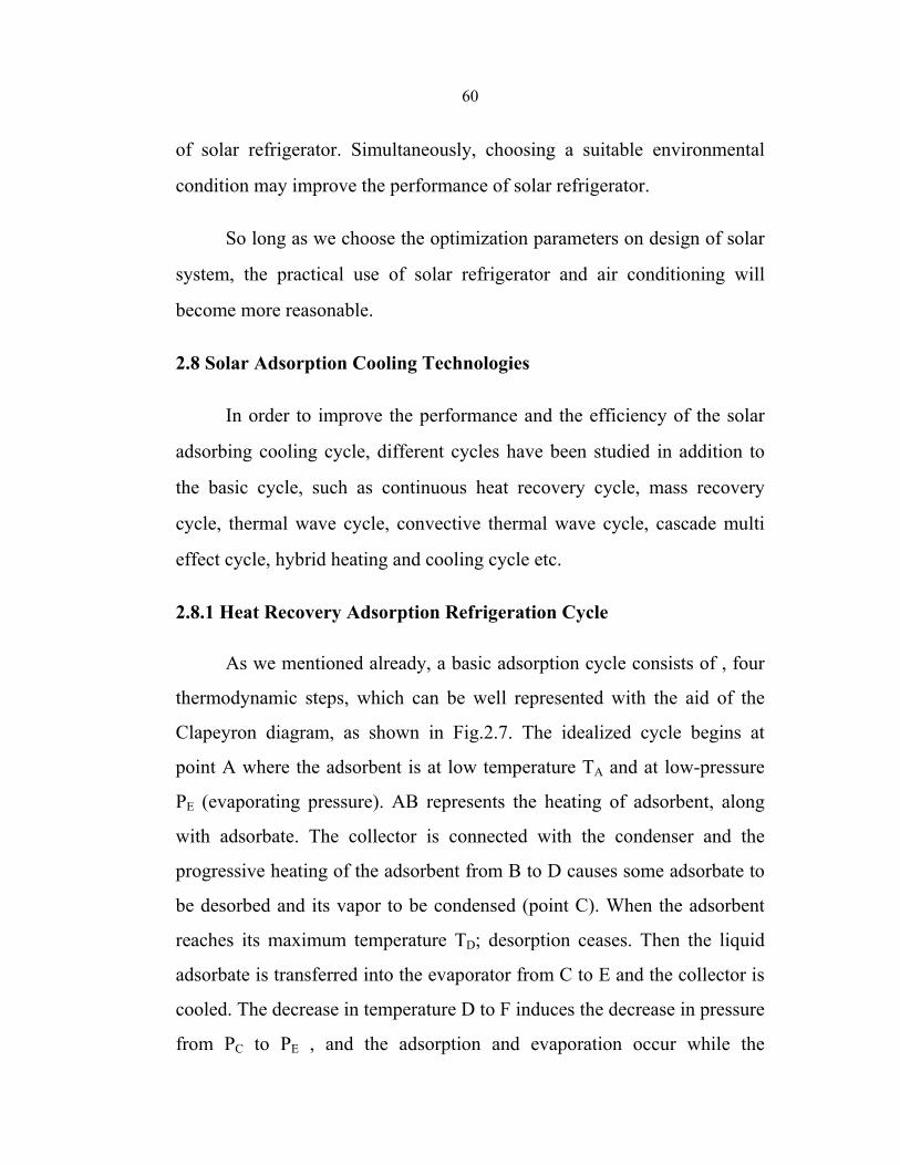
60
of solar refrigerator. Simultaneously, choosing a suitable environmental
condition may improve the performance of solar refrigerator.
So long as we choose the optimization parameters on design of solar
system, the practical use of solar refrigerator and air conditioning will
become more reasonable.
2.8 Solar Adsorption Cooling Technologies
In order to improve the performance and the efficiency of the solar
adsorbing cooling cycle, different cycles have been studied in addition to
the basic cycle, such as continuous heat recovery cycle, mass recovery
cycle, thermal wave cycle, convective thermal wave cycle, cascade multi
effect cycle, hybrid heating and cooling cycle etc.
2.8.1 Heat Recovery Adsorption Refrigeration Cycle
As we mentioned already, a basic adsorption cycle consists of , four
thermodynamic steps, which can be well represented with the aid of the
Clapeyron diagram, as shown in Fig.2.7. The idealized cycle begins at
point A where the adsorbent is at low temperature TA and at low-pressure
PE (evaporating pressure). AB represents the heating of adsorbent, along
with adsorbate. The collector is connected with the condenser and the
progressive heating of the adsorbent from B to D causes some adsorbate to
be desorbed and its vapor to be condensed (point C). When the adsorbent
reaches its maximum temperature TD; desorption ceases. Then the liquid
adsorbate is transferred into the evaporator from C to E and the collector is
cooled. The decrease in temperature D to F induces the decrease in pressure
from PC to PE , and the adsorption and evaporation occur while the
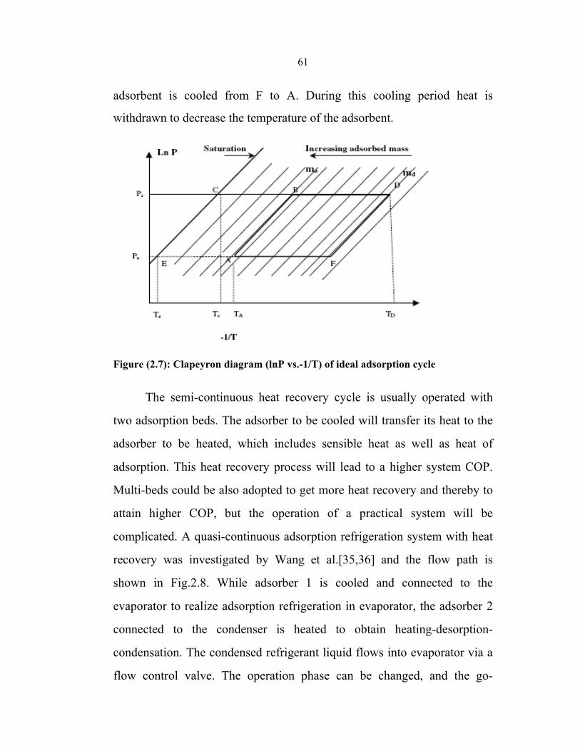
61
adsorbent is cooled from F to A. During this cooling period heat is
withdrawn to decrease the temperature of the adsorbent.
Figure (2.7): Clapeyron diagram (lnP vs.-1/T) of ideal adsorption cycle
The semi-continuous heat recovery cycle is usually operated with
two adsorption beds. The adsorber to be cooled will transfer its heat to the
adsorber to be heated, which includes sensible heat as well as heat of
adsorption. This heat recovery process will lead to a higher system COP.
Multi-beds could be also adopted to get more heat recovery and thereby to
attain higher COP, but the operation of a practical system will be
complicated. A quasi-continuous adsorption refrigeration system with heat
recovery was investigated by Wang et al.[35,36] and the flow path is
shown in Fig.2.8. While adsorber 1 is cooled and connected to the
evaporator to realize adsorption refrigeration in evaporator, the adsorber 2
connected to the condenser is heated to obtain heating-desorption-
condensation. The condensed refrigerant liquid flows into evaporator via a
flow control valve. The operation phase can be changed, and the go-
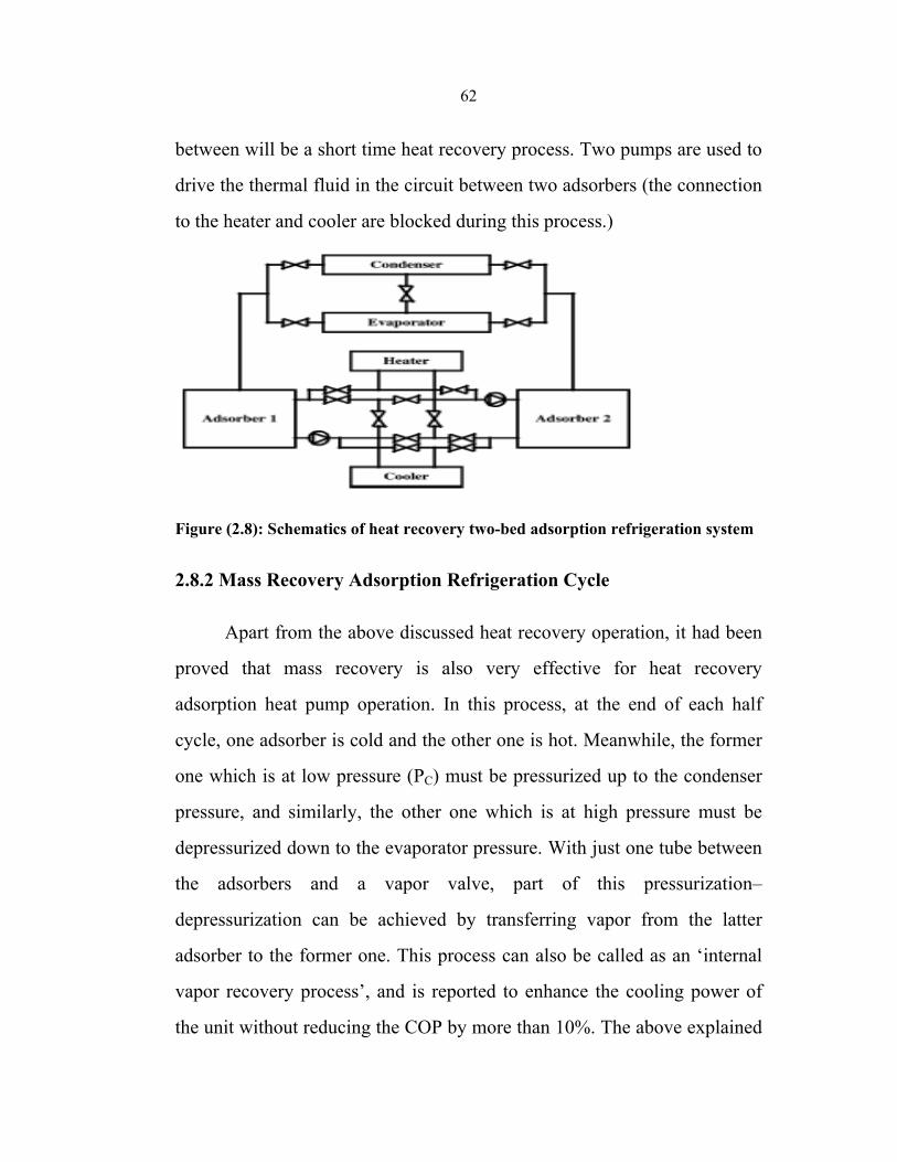
62
between will be a short time heat recovery process. Two pumps are used to
drive the thermal fluid in the circuit between two adsorbers (the connection
to the heater and cooler are blocked during this process.)
Figure (2.8): Schematics of heat recovery two-bed adsorption refrigeration system
2.8.2 Mass Recovery Adsorption Refrigeration Cycle
Apart from the above discussed heat recovery operation, it had been
proved that mass recovery is also very effective for heat recovery
adsorption heat pump operation. In this process, at the end of each half
cycle, one adsorber is cold and the other one is hot. Meanwhile, the former
one which is at low pressure (PC) must be pressurized up to the condenser
pressure, and similarly, the other one which is at high pressure must be
depressurized down to the evaporator pressure. With just one tube between
the adsorbers and a vapor valve, part of this pressurization–
depressurization can be achieved by transferring vapor from the latter
adsorber to the former one. This process can also be called as an ‘internal
vapor recovery process’, and is reported to enhance the cooling power of
the unit without reducing the COP by more than 10%. The above explained
63
process involves only mass transfer and hence the process is rapid. To
obtain a ‘double effect’, mass recovery could be initiated followed by heat
recovery. An ideal heat and mass recovery cycle is shown in Fig 2.9, in
which the heat recovery state for a two bed system is shown by the state
points e –e'.
Figure (2.9): Diagram of heat and mass recovery cycle.
The mass recovery cycle(a2- a3- g'1- g2- g3- a'1- a1- a2 ) is an extended
form of a two bed basic cycle or two bed heat recovery cycle(a2 - g1 -g2 - a1
-a2), and the cycled mass is increased from ∆x to ∆x+ dx, which causes the
refrigeration effect to increase. The principle of these cycles can be
described using Fig.2.9[37]. The very first part of each half cycle is the
mass recovery process (path g2 - g3 and a2 -a3). Then the heat recovery
process proceeds: heat is transferred from the hot adsorber to the cold one
(path g3 – e'). As a consequence, the hot adsorber is first depressurized
(path g3 – a'1), it then adsorbs vapor from the evaporator (path a' – e').
Meanwhile, the cold adsorber is first pressurized (path a3 –g'1), and then
vapor that is desorbed passes into the condenser (path g'1 - e).
Theoretically, the heat recovery process develops until the adsorbers reach
the same temperature. Actually, there still remains a temperature difference
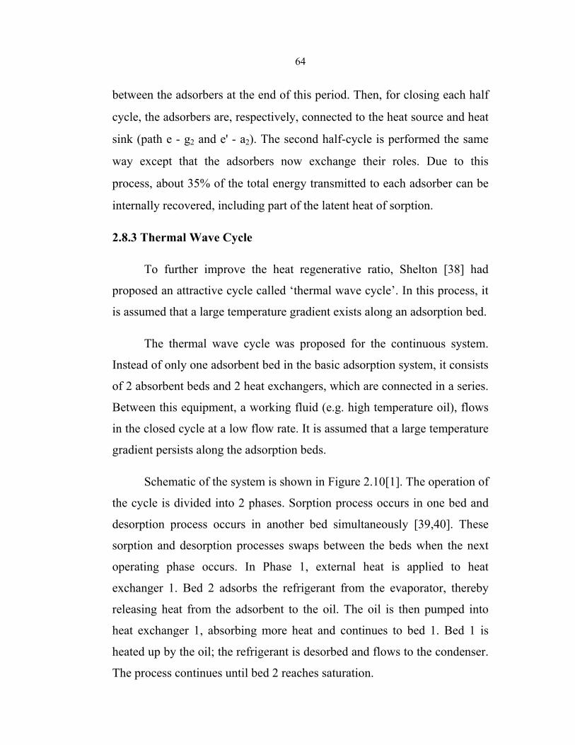
64
between the adsorbers at the end of this period. Then, for closing each half
cycle, the adsorbers are, respectively, connected to the heat source and heat
sink (path e - g2 and e' - a2). The second half-cycle is performed the same
way except that the adsorbers now exchange their roles. Due to this
process, about 35% of the total energy transmitted to each adsorber can be
internally recovered, including part of the latent heat of sorption.
2.8.3 Thermal Wave Cycle
To further improve the heat regenerative ratio, Shelton [38] had
proposed an attractive cycle called ‘thermal wave cycle’. In this process, it
is assumed that a large temperature gradient exists along an adsorption bed.
The thermal wave cycle was proposed for the continuous system.
Instead of only one adsorbent bed in the basic adsorption system, it consists
of 2 absorbent beds and 2 heat exchangers, which are connected in a series.
Between this equipment, a working fluid (e.g. high temperature oil), flows
in the closed cycle at a low flow rate. It is assumed that a large temperature
gradient persists along the adsorption beds.
Schematic of the system is shown in Figure 2.10[1]. The operation of
the cycle is divided into 2 phases. Sorption process occurs in one bed and
desorption process occurs in another bed simultaneously [39,40]. These
sorption and desorption processes swaps between the beds when the next
operating phase occurs. In Phase 1, external heat is applied to heat
exchanger 1. Bed 2 adsorbs the refrigerant from the evaporator, thereby
releasing heat from the adsorbent to the oil. The oil is then pumped into
heat exchanger 1, absorbing more heat and continues to bed 1. Bed 1 is
heated up by the oil; the refrigerant is desorbed and flows to the condenser.
The process continues until bed 2 reaches saturation.
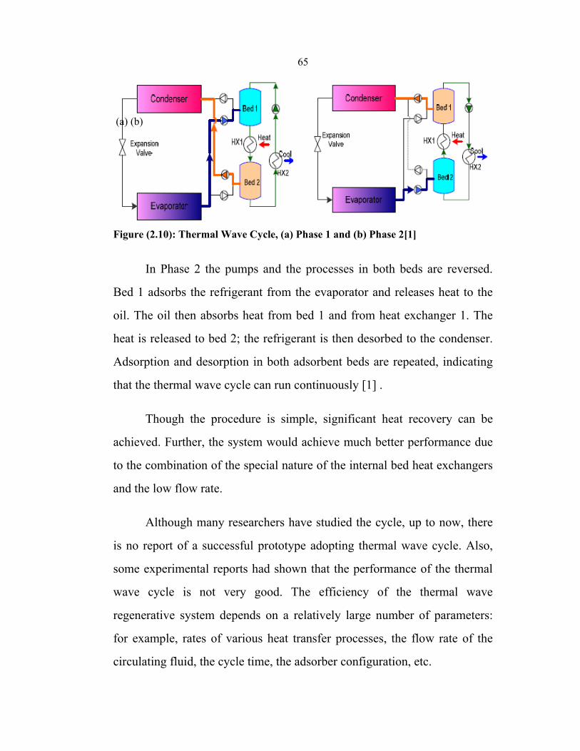
65
(a) (b)
Figure (2.10): Thermal Wave Cycle, (a) Phase 1 and (b) Phase 2[1]
In Phase 2 the pumps and the processes in both beds are reversed.
Bed 1 adsorbs the refrigerant from the evaporator and releases heat to the
oil. The oil then absorbs heat from bed 1 and from heat exchanger 1. The
heat is released to bed 2; the refrigerant is then desorbed to the condenser.
Adsorption and desorption in both adsorbent beds are repeated, indicating
that the thermal wave cycle can run continuously [1] .
Though the procedure is simple, significant heat recovery can be
achieved. Further, the system would achieve much better performance due
to the combination of the special nature of the internal bed heat exchangers
and the low flow rate.
Although many researchers have studied the cycle, up to now, there
is no report of a successful prototype adopting thermal wave cycle. Also,
some experimental reports had shown that the performance of the thermal
wave cycle is not very good. The efficiency of the thermal wave
regenerative system depends on a relatively large number of parameters:
for example, rates of various heat transfer processes, the flow rate of the
circulating fluid, the cycle time, the adsorber configuration, etc.
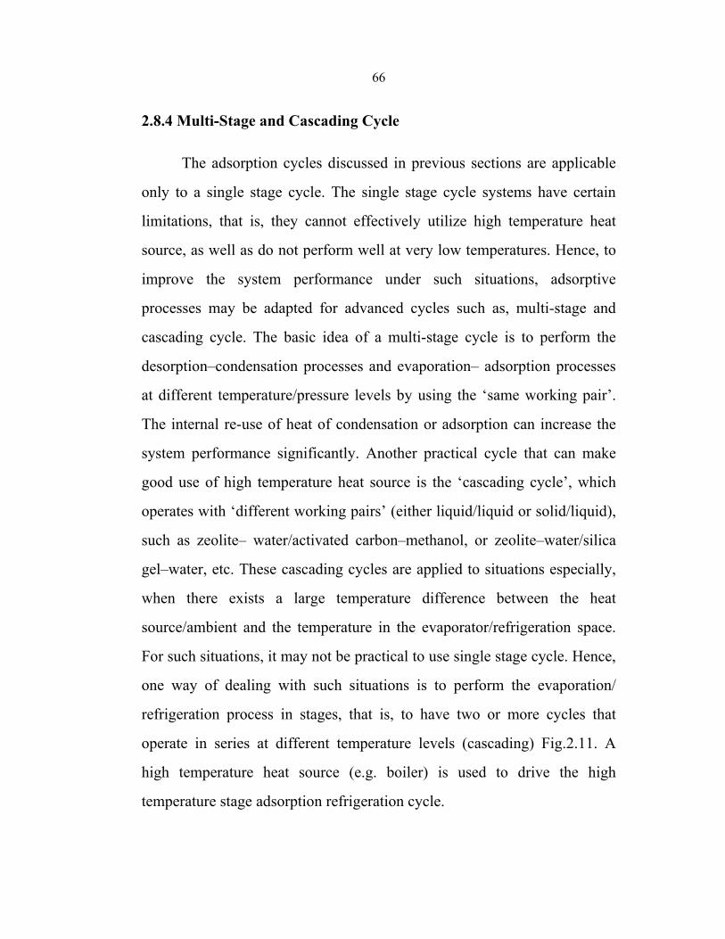
66
2.8.4 Multi-Stage and Cascading Cycle
The adsorption cycles discussed in previous sections are applicable
only to a single stage cycle. The single stage cycle systems have certain
limitations, that is, they cannot effectively utilize high temperature heat
source, as well as do not perform well at very low temperatures. Hence, to
improve the system performance under such situations, adsorptive
processes may be adapted for advanced cycles such as, multi-stage and
cascading cycle. The basic idea of a multi-stage cycle is to perform the
desorption–condensation processes and evaporation– adsorption processes
at different temperature/pressure levels by using the ‘same working pair’.
The internal re-use of heat of condensation or adsorption can increase the
system performance significantly. Another practical cycle that can make
good use of high temperature heat source is the ‘cascading cycle’, which
operates with ‘different working pairs’ (either liquid/liquid or solid/liquid),
such as zeolite– water/activated carbon–methanol, or zeolite–water/silica
gel–water, etc. These cascading cycles are applied to situations especially,
when there exists a large temperature difference between the heat
source/ambient and the temperature in the evaporator/refrigeration space.
For such situations, it may not be practical to use single stage cycle. Hence,
one way of dealing with such situations is to perform the evaporation/
refrigeration process in stages, that is, to have two or more cycles that
operate in series at different temperature levels (cascading) Fig.2.11. A
high temperature heat source (e.g. boiler) is used to drive the high
temperature stage adsorption refrigeration cycle.
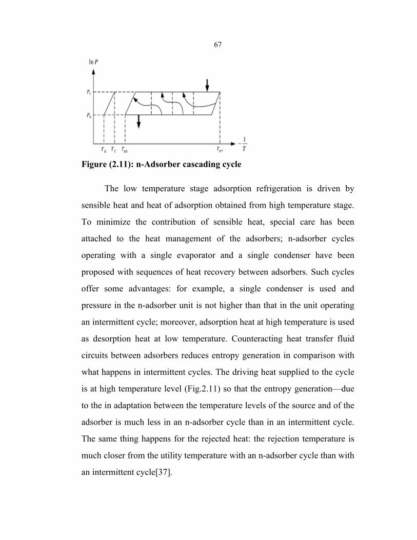
67
Figure (2.11): n-Adsorber cascading cycle
The low temperature stage adsorption refrigeration is driven by
sensible heat and heat of adsorption obtained from high temperature stage.
To minimize the contribution of sensible heat, special care has been
attached to the heat management of the adsorbers; n-adsorber cycles
operating with a single evaporator and a single condenser have been
proposed with sequences of heat recovery between adsorbers. Such cycles
offer some advantages: for example, a single condenser is used and
pressure in the n-adsorber unit is not higher than that in the unit operating
an intermittent cycle; moreover, adsorption heat at high temperature is used
as desorption heat at low temperature. Counteracting heat transfer fluid
circuits between adsorbers reduces entropy generation in comparison with
what happens in intermittent cycles. The driving heat supplied to the cycle
is at high temperature level (Fig.2.11) so that the entropy generation—due
to the in adaptation between the temperature levels of the source and of the
adsorber is much less in an n-adsorber cycle than in an intermittent cycle.
The same thing happens for the rejected heat: the rejection temperature is
much closer from the utility temperature with an n-adsorber cycle than with
an intermittent cycle[37].
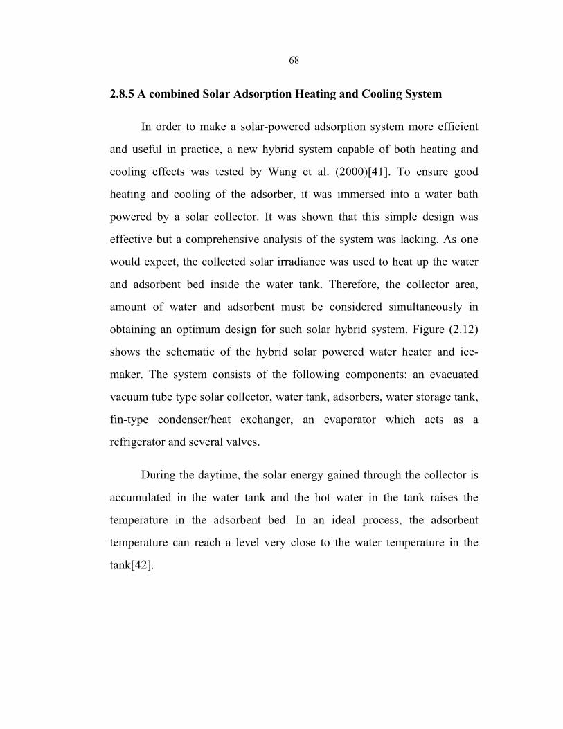
68
2.8.5 A combined Solar Adsorption Heating and Cooling System
In order to make a solar-powered adsorption system more efficient
and useful in practice, a new hybrid system capable of both heating and
cooling effects was tested by Wang et al. (2000)[41]. To ensure good
heating and cooling of the adsorber, it was immersed into a water bath
powered by a solar collector. It was shown that this simple design was
effective but a comprehensive analysis of the system was lacking. As one
would expect, the collected solar irradiance was used to heat up the water
and adsorbent bed inside the water tank. Therefore, the collector area,
amount of water and adsorbent must be considered simultaneously in
obtaining an optimum design for such solar hybrid system. Figure (2.12)
shows the schematic of the hybrid solar powered water heater and ice-
maker. The system consists of the following components: an evacuated
vacuum tube type solar collector, water tank, adsorbers, water storage tank,
fin-type condenser/heat exchanger, an evaporator which acts as a
refrigerator and several valves.
During the daytime, the solar energy gained through the collector is
accumulated in the water tank and the hot water in the tank raises the
temperature in the adsorbent bed. In an ideal process, the adsorbent
temperature can reach a level very close to the water temperature in the
tank[42].
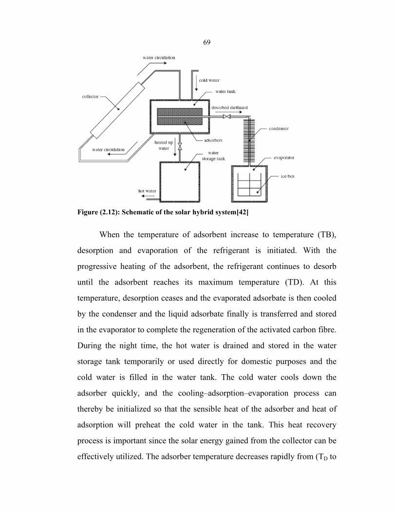
69
Figure (2.12): Schematic of the solar hybrid system[42]
When the temperature of adsorbent increase to temperature (TB),
desorption and evaporation of the refrigerant is initiated. With the
progressive heating of the adsorbent, the refrigerant continues to desorb
until the adsorbent reaches its maximum temperature (TD). At this
temperature, desorption ceases and the evaporated adsorbate is then cooled
by the condenser and the liquid adsorbate finally is transferred and stored
in the evaporator to complete the regeneration of the activated carbon fibre.
During the night time, the hot water is drained and stored in the water
storage tank temporarily or used directly for domestic purposes and the
cold water is filled in the water tank. The cold water cools down the
adsorber quickly, and the cooling–adsorption–evaporation process can
thereby be initialized so that the sensible heat of the adsorber and heat of
adsorption will preheat the cold water in the tank. This heat recovery
process is important since the solar energy gained from the collector can be
effectively utilized. The adsorber temperature decreases rapidly from (TD to
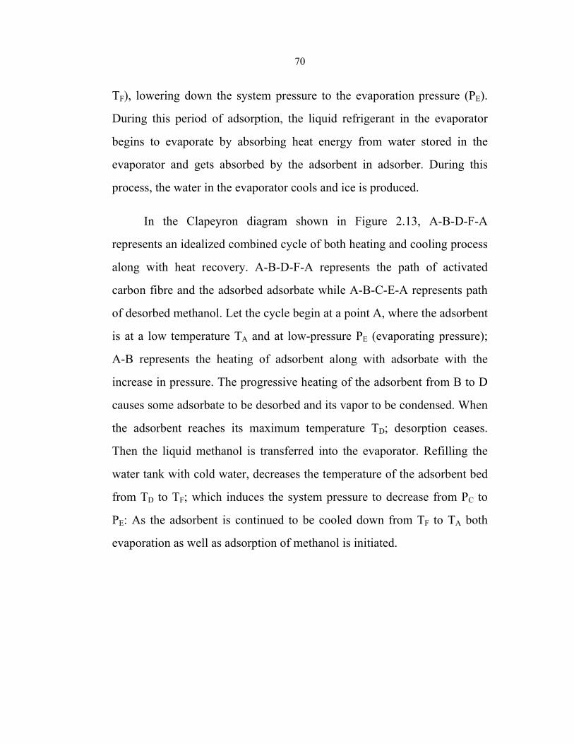
70
TF), lowering down the system pressure to the evaporation pressure (PE).
During this period of adsorption, the liquid refrigerant in the evaporator
begins to evaporate by absorbing heat energy from water stored in the
evaporator and gets absorbed by the adsorbent in adsorber. During this
process, the water in the evaporator cools and ice is produced.
In the Clapeyron diagram shown in Figure 2.13, A-B-D-F-A
represents an idealized combined cycle of both heating and cooling process
along with heat recovery. A-B-D-F-A represents the path of activated
carbon fibre and the adsorbed adsorbate while A-B-C-E-A represents path
of desorbed methanol. Let the cycle begin at a point A, where the adsorbent
is at a low temperature TA and at low-pressure PE (evaporating pressure);
A-B represents the heating of adsorbent along with adsorbate with the
increase in pressure. The progressive heating of the adsorbent from B to D
causes some adsorbate to be desorbed and its vapor to be condensed. When
the adsorbent reaches its maximum temperature TD; desorption ceases.
Then the liquid methanol is transferred into the evaporator. Refilling the
water tank with cold water, decreases the temperature of the adsorbent bed
from TD to TF; which induces the system pressure to decrease from PC to
PE: As the adsorbent is continued to be cooled down from TF to TA both
evaporation as well as adsorption of methanol is initiated.
71
Figure (2.13): Clapeyron diagram (ln P Vs –1/T) of ideal adsorption cycle
During this cooling period, heat is rejected both to decrease the
temperature of the adsorbent and to withdraw adsorption heat. The
adsorption bed is the heart of a solid adsorption refrigeration system. Its
characteristics play an important factor in the successful operation of such
systems. To make sure an adsorption system is more efficient, it requires
adsorbers with both good heat collecting and heat releasing. Hence, by
using the above described hybrid water heating and ice-making system, it is
possible to recover the heat rejected during the adsorption process and
make the system be effective in two ways. But, such design has one main
disadvantage; the heat transfer inside the adsorbent bed is low which leads
to a decrease in the system performance. It is because the encapsulation
thickness of adsorbent is so large that the temperature difference of
adsorbent between surface layer and bottom of the bed becomes too high
for adsorbent to either adsorb or desorb evenly. Also, the heat conduction
ability of an adsorbent bed is not very good. To overcome these
shortcomings of the adsorbent bed, instead of using traditionally used
single bed adsorber, more adsorbers can be used to increase the heat
transfer area. This adsorbent bed is generally known as ‘adsorber
manifolds’ (Figure 2.14)[42].
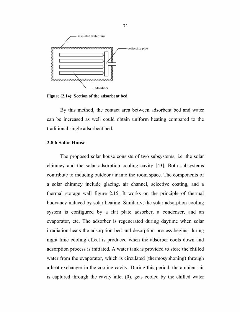
72
Figure (2.14): Section of the adsorbent bed
By this method, the contact area between adsorbent bed and water
can be increased as well could obtain uniform heating compared to the
traditional single adsorbent bed.
2.8.6 Solar House
The proposed solar house consists of two subsystems, i.e. the solar
chimney and the solar adsorption cooling cavity [43]. Both subsystems
contribute to inducing outdoor air into the room space. The components of
a solar chimney include glazing, air channel, selective coating, and a
thermal storage wall figure 2.15. It works on the principle of thermal
buoyancy induced by solar heating. Similarly, the solar adsorption cooling
system is configured by a flat plate adsorber, a condenser, and an
evaporator, etc. The adsorber is regenerated during daytime when solar
irradiation heats the adsorption bed and desorption process begins; during
night time cooling effect is produced when the adsorber cools down and
adsorption process is initiated. A water tank is provided to store the chilled
water from the evaporator, which is circulated (thermosyphoning) through
a heat exchanger in the cooling cavity. During this period, the ambient air
is captured through the cavity inlet (0), gets cooled by the chilled water
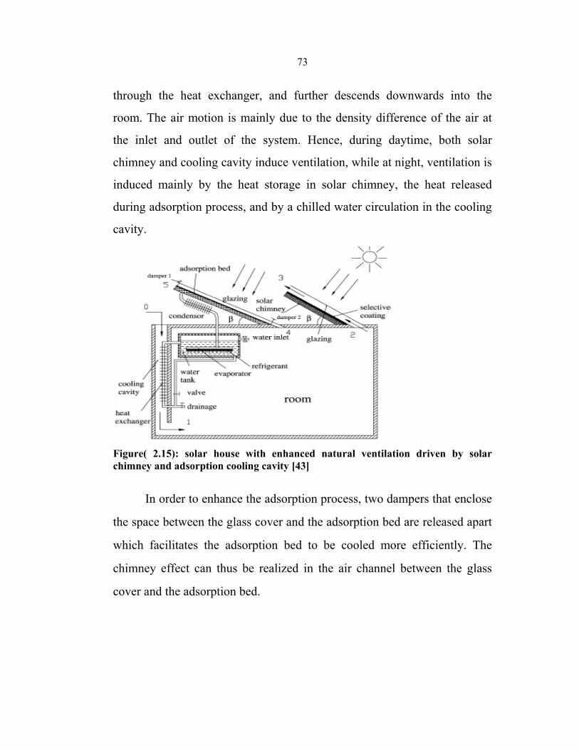
73
through the heat exchanger, and further descends downwards into the
room. The air motion is mainly due to the density difference of the air at
the inlet and outlet of the system. Hence, during daytime, both solar
chimney and cooling cavity induce ventilation, while at night, ventilation is
induced mainly by the heat storage in solar chimney, the heat released
during adsorption process, and by a chilled water circulation in the cooling
cavity.
Figure( 2.15): solar house with enhanced natural ventilation driven by solar chimney and adsorption cooling cavity [43]
In order to enhance the adsorption process, two dampers that enclose
the space between the glass cover and the adsorption bed are released apart
which facilitates the adsorption bed to be cooled more efficiently. The
chimney effect can thus be realized in the air channel between the glass
cover and the adsorption bed.
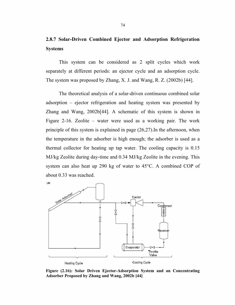
74
2.8.7 Solar-Driven Combined Ejector and Adsorption Refrigeration
Systems
This system can be considered as 2 split cycles which work
separately at different periods: an ejector cycle and an adsorption cycle.
The system was proposed by Zhang, X. J. and Wang, R. Z. (2002b) [44].
The theoretical analysis of a solar-driven continuous combined solar
adsorption – ejector refrigeration and heating system was presented by
Zhang and Wang, 2002b[44]. A schematic of this system is shown in
Figure 2-16. Zeolite – water were used as a working pair. The work
principle of this system is explained in page (26,27).In the afternoon, when
the temperature in the adsorber is high enough; the adsorber is used as a
thermal collector for heating up tap water. The cooling capacity is 0.15
MJ/kg Zeolite during day-time and 0.34 MJ/kg Zeolite in the evening. This
system can also heat up 290 kg of water to 45°C. A combined COP of
about 0.33 was reached.
Figure (2.16): Solar Driven Ejector-Adsorption System and an Concentrating Adsorber Proposed by Zhang and Wang, 2002b [44]
75
Chapter Three Potential of Solar Energy in Palestine
3.1 Solar Energy
The basic resource for all solar energy systems is the sun.
Knowledge of the quantity and quality of solar energy available at a
specific location is of prime importance for the design of any solar energy
system. Although the solar radiation (insolation) is relatively constant
outside the earth's atmosphere, local climate influences can cause wide
variations in available insolation on the earth’s surface from site to site. In
addition, the relative motion of the sun with respect to the earth will allow
surfaces with different orientations to intercept different amounts of solar
energy. Figure 3.1 shows regions of high insulation where solar energy
conversion systems will produce the maximum amount of energy from a
specific collector field size[45].
In Palestine also we have very good potential of solar radiation and
it could be used for many purposes, however, solar energy is available over
the entire globe, and only the size of the solar system needs to be increased
to provide the same amount of heat or electricity as in the shaded areas. It
is the primary task of the solar energy system designer to determine the
amount, quality and timing of the solar energy available at the site selected
for installing a solar energy conversion system.
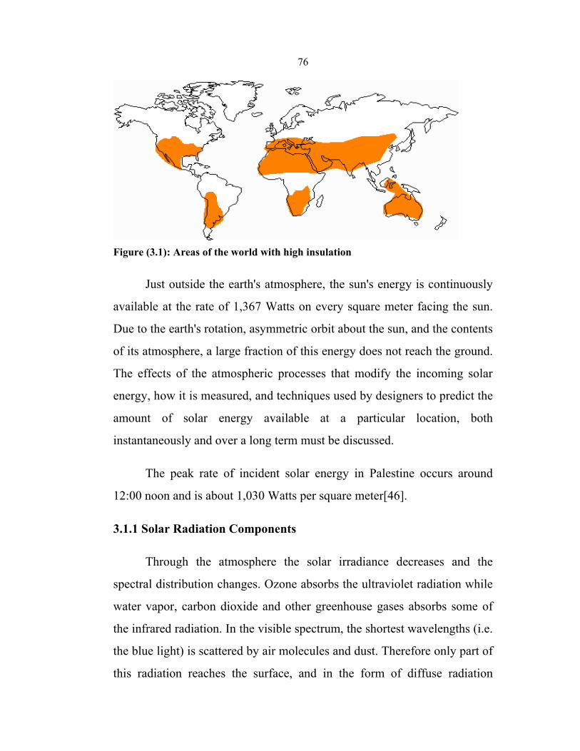
76
Figure (3.1): Areas of the world with high insulation
Just outside the earth's atmosphere, the sun's energy is continuously
available at the rate of 1,367 Watts on every square meter facing the sun.
Due to the earth's rotation, asymmetric orbit about the sun, and the contents
of its atmosphere, a large fraction of this energy does not reach the ground.
The effects of the atmospheric processes that modify the incoming solar
energy, how it is measured, and techniques used by designers to predict the
amount of solar energy available at a particular location, both
instantaneously and over a long term must be discussed.
The peak rate of incident solar energy in Palestine occurs around
12:00 noon and is about 1,030 Watts per square meter[46].
3.1.1 Solar Radiation Components
Through the atmosphere the solar irradiance decreases and the
spectral distribution changes. Ozone absorbs the ultraviolet radiation while
water vapor, carbon dioxide and other greenhouse gases absorbs some of
the infrared radiation. In the visible spectrum, the shortest wavelengths (i.e.
the blue light) is scattered by air molecules and dust. Therefore only part of
this radiation reaches the surface, and in the form of diffuse radiation
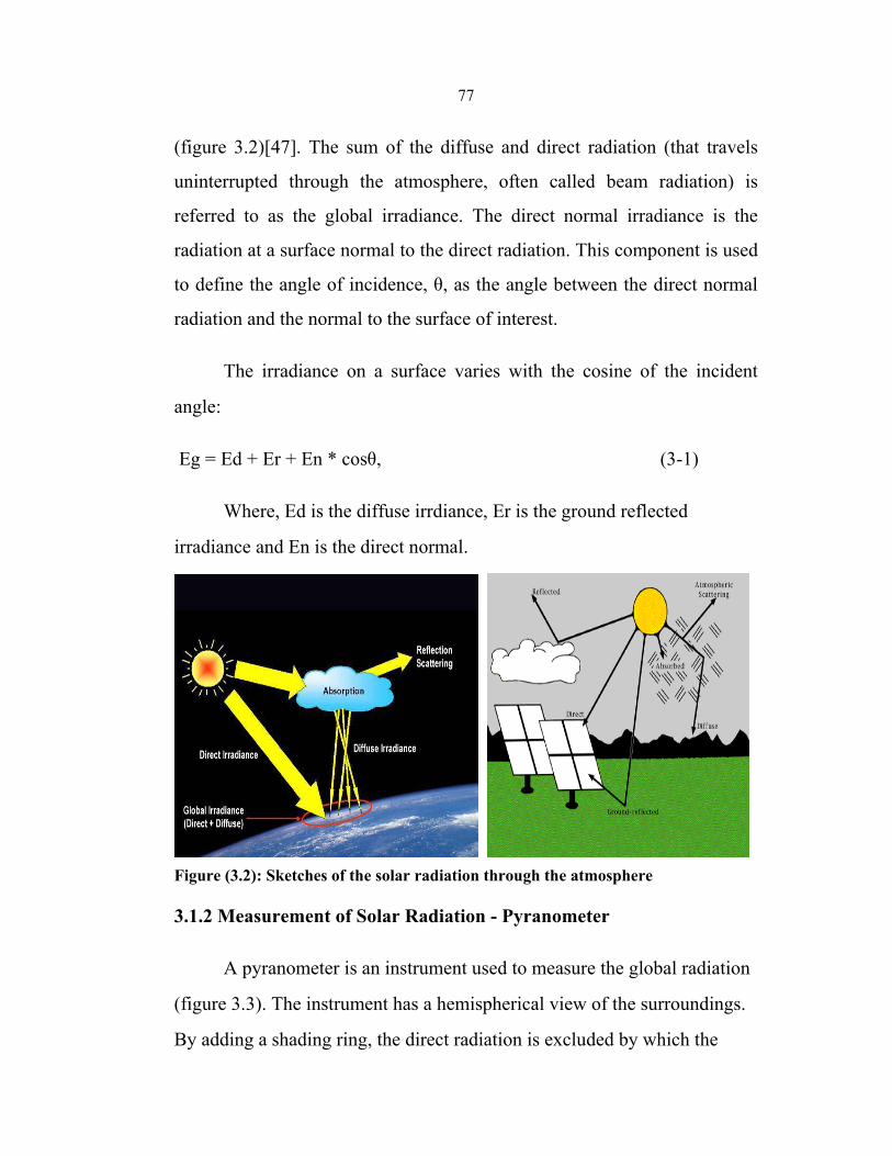
77
(figure 3.2)[47]. The sum of the diffuse and direct radiation (that travels
uninterrupted through the atmosphere, often called beam radiation) is
referred to as the global irradiance. The direct normal irradiance is the
radiation at a surface normal to the direct radiation. This component is used
to define the angle of incidence, θ, as the angle between the direct normal
radiation and the normal to the surface of interest.
The irradiance on a surface varies with the cosine of the incident
angle:
Eg = Ed + Er + En * cosθ, (3-1)
Where, Ed is the diffuse irrdiance, Er is the ground reflected
irradiance and En is the direct normal.
Figure (3.2): Sketches of the solar radiation through the atmosphere
3.1.2 Measurement of Solar Radiation - Pyranometer
A pyranometer is an instrument used to measure the global radiation
(figure 3.3). The instrument has a hemispherical view of the surroundings.
By adding a shading ring, the direct radiation is excluded by which the
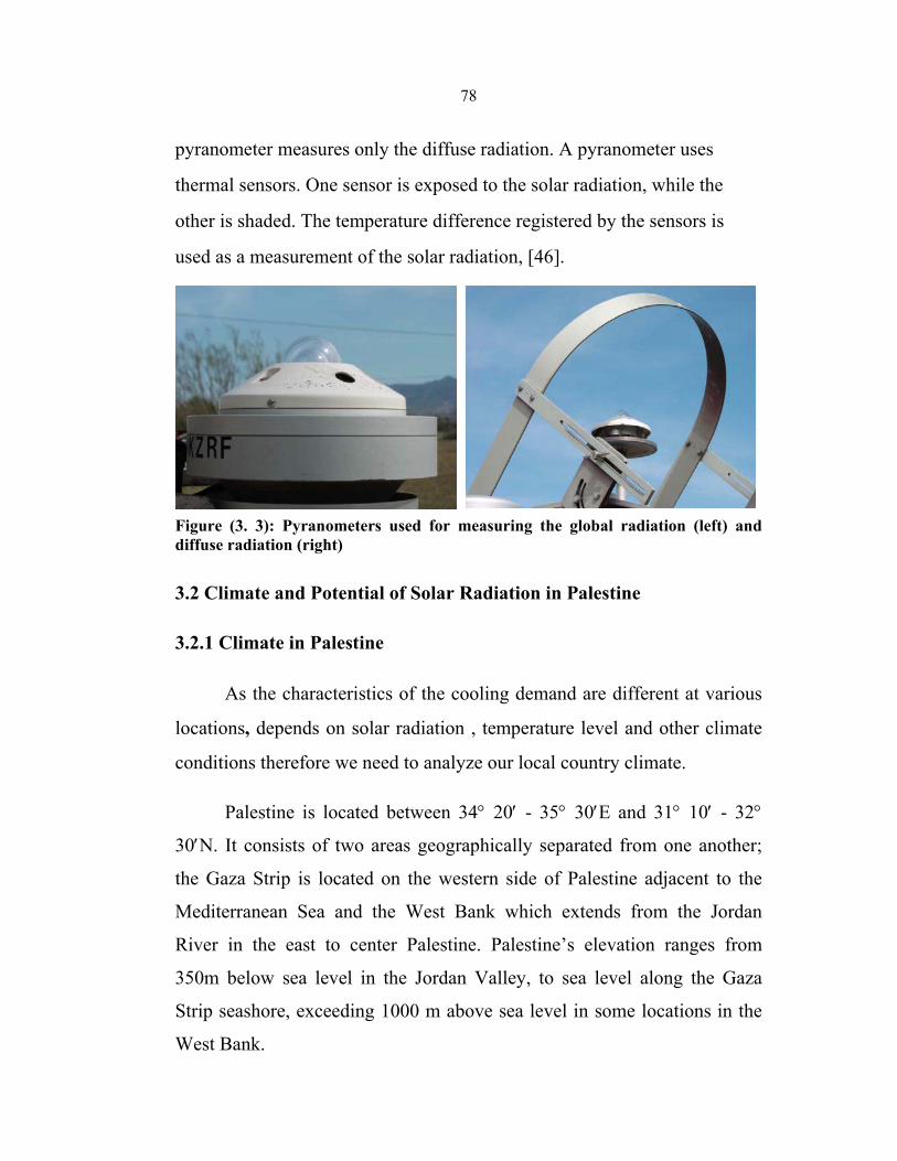
78
pyranometer measures only the diffuse radiation. A pyranometer uses
thermal sensors. One sensor is exposed to the solar radiation, while the
other is shaded. The temperature difference registered by the sensors is
used as a measurement of the solar radiation, [46].
Figure (3. 3): Pyranometers used for measuring the global radiation (left) and diffuse radiation (right)
3.2 Climate and Potential of Solar Radiation in Palestine
3.2.1 Climate in Palestine
As the characteristics of the cooling demand are different at various
locations, depends on solar radiation , temperature level and other climate
conditions therefore we need to analyze our local country climate.
Palestine is located between 34° 20′ - 35° 30′E and 31° 10′ - 32°
30′N. It consists of two areas geographically separated from one another;
the Gaza Strip is located on the western side of Palestine adjacent to the
Mediterranean Sea and the West Bank which extends from the Jordan
River in the east to center Palestine. Palestine’s elevation ranges from
350m below sea level in the Jordan Valley, to sea level along the Gaza
Strip seashore, exceeding 1000 m above sea level in some locations in the
West Bank.
79
Climate conditions in Palestine vary widely. The coastal climate in
Gaza Strip is humid and hot during summer and mild during winter. These
areas have low heating loads, while cooling is required during summer. The
daily average temperature and relative humidity vary in the ranges:13.3 -
25.4 C° and 67 - 75% respectively. In the hilly areas of the West Bank,
cold winter conditions and mild summer weather are prevalent. Daily
average temperature and relative humidity vary in the ranges: 8 - 23 °C and
51 - 83% respectively. In some areas the temperature decline below 0°C.
Hence, high heating loads are required, while little cooling is needed during
summer. In Jericho and the Jordan Valley, almost no heating is needed
during winter while high cooling during summer is needed[48].
3.2.2 Potential of Solar Energy in Palestine
Palestine has high solar energy potential, it has about 3000 sunshine
hours per year and high annual average of solar radiation amounting to 5.4
kWh/m2 – day (19.44MJ) on horizontal surface, which classified as a high
solar energy potential. The lowest solar energy average is in December, it
amounts to 2.63 kWh/ m2 - day. The solar radiation on horizontal surface
varies from 2.63 kWh/m2-day in December to 8.4 kWh/m2 - day in
June[46]. Table 3.1 and figure 3.4 shows the average total solar radiation
per day for each month during 2006 at Jenin city as an example of West
Bank region.
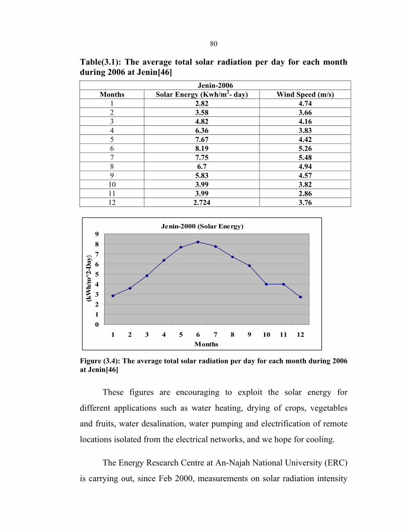
80
Table(3.1): The average total solar radiation per day for each month during 2006 at Jenin[46]
Jenin-2006 Months Solar Energy (Kwh/m2- day) Wind Speed (m/s)
1 2.82 4.74 2 3.58 3.66 3 4.82 4.16 4 6.36 3.83 5 7.67 4.42 6 8.19 5.26 7 7.75 5.48 8 6.7 4.94 9 5.83 4.57 10 3.99 3.82 11 3.99 2.86 12 2.724 3.76
Jenin-2000 (Solar Energy)
0123456789
1 2 3 4 5 6 7 8 9 10 11 12Months
(kW
h/m
2̂-D
ay)
Figure (3.4): The average total solar radiation per day for each month during 2006 at Jenin[46]
These figures are encouraging to exploit the solar energy for
different applications such as water heating, drying of crops, vegetables
and fruits, water desalination, water pumping and electrification of remote
locations isolated from the electrical networks, and we hope for cooling.
The Energy Research Centre at An-Najah National University (ERC)
is carrying out, since Feb 2000, measurements on solar radiation intensity
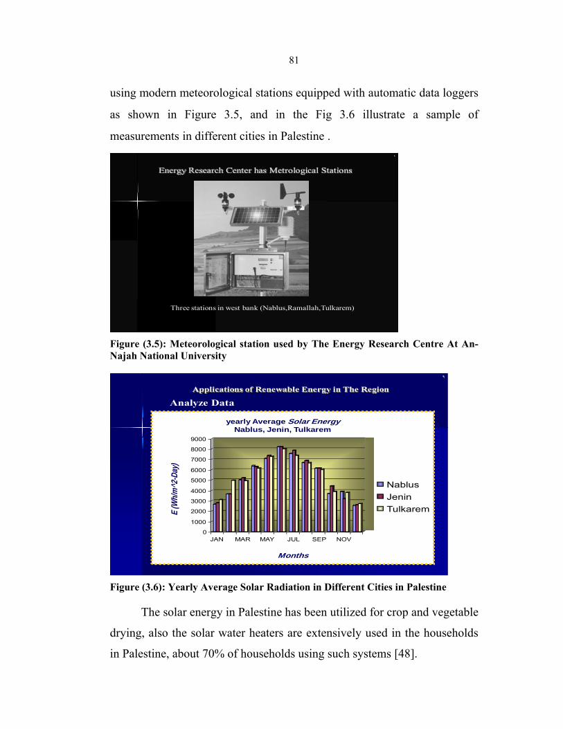
81
using modern meteorological stations equipped with automatic data loggers
as shown in Figure 3.5, and in the Fig 3.6 illustrate a sample of
measurements in different cities in Palestine . ١
Energy Research Center has Metrological Stations
Three stations in west bank (Nablus,Ramallah,Tulkarem)
Figure (3.5): Meteorological station used by The Energy Research Centre At An- Najah National University
٩
0
1000
2000
3000
4000
5000
6000
7000
8000
9000
JAN MAR MAY JUL SEP NOV
NablusJeninTulkarem
yearly Average Solar EnergyNablus, Jenin, Tulkarem
E (W
h/m^2
-Day
)
Months
Analyze Data Applications of Renewable Energy in The Region
Figure (3.6): Yearly Average Solar Radiation in Different Cities in Palestine
The solar energy in Palestine has been utilized for crop and vegetable
drying, also the solar water heaters are extensively used in the households
in Palestine, about 70% of households using such systems [48].
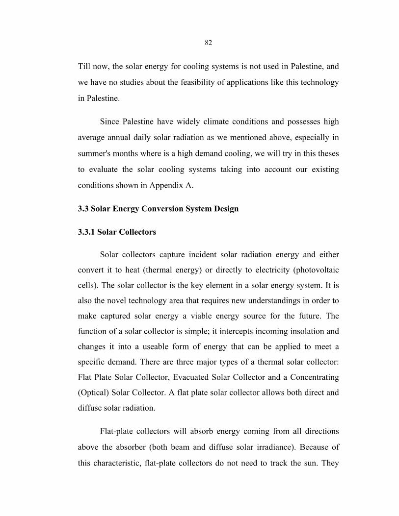
82
Till now, the solar energy for cooling systems is not used in Palestine, and
we have no studies about the feasibility of applications like this technology
in Palestine.
Since Palestine have widely climate conditions and possesses high
average annual daily solar radiation as we mentioned above, especially in
summer's months where is a high demand cooling, we will try in this theses
to evaluate the solar cooling systems taking into account our existing
conditions shown in Appendix A.
3.3 Solar Energy Conversion System Design
3.3.1 Solar Collectors
Solar collectors capture incident solar radiation energy and either
convert it to heat (thermal energy) or directly to electricity (photovoltaic
cells). The solar collector is the key element in a solar energy system. It is
also the novel technology area that requires new understandings in order to
make captured solar energy a viable energy source for the future. The
function of a solar collector is simple; it intercepts incoming insolation and
changes it into a useable form of energy that can be applied to meet a
specific demand. There are three major types of a thermal solar collector:
Flat Plate Solar Collector, Evacuated Solar Collector and a Concentrating
(Optical) Solar Collector. A flat plate solar collector allows both direct and
diffuse solar radiation.
Flat-plate collectors will absorb energy coming from all directions
above the absorber (both beam and diffuse solar irradiance). Because of
this characteristic, flat-plate collectors do not need to track the sun. They
83
receive more solar energy than a similarly oriented concentrating collector,
but when not tracked, have greater cosine losses [49].
Since tracking is not required, flat-plate collectors may be firmly
fixed to a mounting structure, and rigid plumbing may be used to connect
the collectors to the remainder of the system. Also the flat-plate collector
absorbs both the direct and the diffuse components of solar radiation. This
partially compensates for the fact that fixed surfaces receive less energy
because of the cosine effect. Although the diffuse solar irradiance is only
about 10 percent of the direct normal solar irradiance on a clear day, on a
cloudy day almost all of the available solar irradiance is diffuse.
Currently, flat-plate collectors cost less than concentrating collectors.
Part of reason is the lack of need for a complex tracking system.
3.3.2 Collector Performance
1. Orientation
The orientation of a flat-plate collector is a concern in system design.
The designer must decide on both the collector azimuth and tilt angles or to
install the collectors horizontally.
2. Economic and Environmental Considerations
The most important factor driving the solar energy system design
process is whether the energy it produces is economical. Although there are
factors other than economics that enter into a decision of when to use solar
energy; i.e. no pollution, no greenhouse gas generation, security of the
energy resource etc., design decisions are almost exclusively dominated by

84
the ‘levelized energy cost’. This or some similar economic parameter, gives
the expected cost of the energy produced by the solar energy system
averaged over the lifetime of the system.
3. Efficiency Measurement
The energy collection efficiency is normally determined by testing.
Collector performance test data are correlated with a parameter comprised
of the collector temperature rise above ambient divided by the solar
irradiance[49]. For flat-plate collector performance, the collector
temperature and the solar irradiance used in this correlation are different
from those used for concentrating collectors.
The energy balance on a solar collector absorber or receiver can be
written as;
Quseful = Eopt - Qloss (3.2)
where: Quseful - rate of ‘useful’ energy leaving the absorber
Eopt - rate of optical (short wavelength) radiation incident on absorber
Qloss - rate of thermal energy loss from the absorber
The ‘useful’ energy for a solar thermal collector is the rate of thermal
energy leaving the collector, usually described in terms of the rate of
energy being added to a heat transfer fluid passing through the receiver or
absorber, i.e.:
Quseful = mcp (Tout – T in ) (3.3)
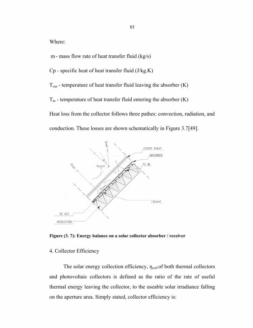
85
Where:
m - mass flow rate of heat transfer fluid (kg/s)
Cp - specific heat of heat transfer fluid (J/kg.K)
Tout - temperature of heat transfer fluid leaving the absorber (K)
Tin - temperature of heat transfer fluid entering the absorber (K)
Heat loss from the collector follows three pathes: convection, radiation, and
conduction. These losses are shown schematically in Figure 3.7[49].
Figure (3. 7): Energy balance on a solar collector absorber / receiver
4. Collector Efficiency
The solar energy collection efficiency, ηcoll of both thermal collectors
and photovoltaic collectors is defined as the ratio of the rate of useful
thermal energy leaving the collector, to the useable solar irradiance falling
on the aperture area. Simply stated, collector efficiency is:
86
ηcoll = Quseful/ AaIa (3.4)
where:
Quseful = rate of (useful) energy output (W)
Aa = aperture area of the collector (m2)
Ia = solar irradiance falling on collector aperture (W/m2)
This general definition of collector efficiency differs depending on
the type of collector. The rate of useful energy output from thermal
collectors is the heat addition to a heat transfer fluid as defined by Equation
(3.2). Since flat-plate collectors (both thermal and photovoltaic) are capable
of absorbing both direct (beam) and diffuse solar irradiance, the appropriate
aperture irradiance is the global (total) irradiance falling on the collector
aperture.
Ia = It,a (3.5)
where It,a is the global irradiance on a collector aperture.
The collector efficiency of the thermal and photovoltaic flat-plate
collectors, then has the following definitions:
Flat-plate thermal collectors:
ηcol = mcp (Tout – T in ) / It,aAa (3.6)
Flat-plate photovoltaic collectors:
ηcoll = i.v / It,aAa (3.7)
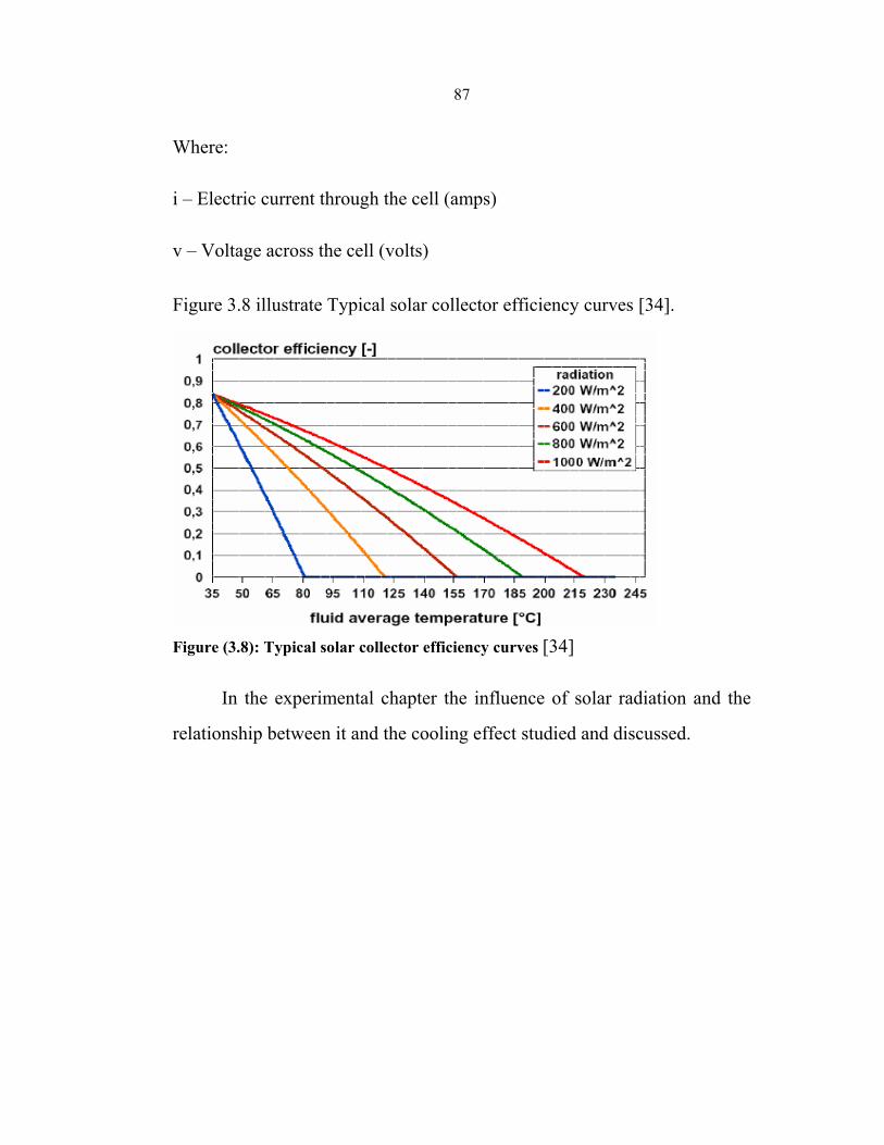
87
Where:
i – Electric current through the cell (amps)
v – Voltage across the cell (volts)
Figure 3.8 illustrate Typical solar collector efficiency curves [34].
Figure (3.8): Typical solar collector efficiency curves [34]
In the experimental chapter the influence of solar radiation and the
relationship between it and the cooling effect studied and discussed.
88
Chapter Four
Experimental Work, Results and Discussion
4.1 Working Principle of the No Valve Solar Cooler
A no valve, flat plate solar cooler is designed to meet the objective of
this thesis by doing a large number of experiments and theory analysis.
There are no valves and measure gauges installed on this advanced device
except for experimental purposes, also there are no moving parts on this
device. Activated carbon and methanol are used as working pair for this no
valve solar cooler. Fig. 4.1 shows schematic layout of a no valve solar flat
plate cooler. The solar cooler consists of a adsorbent bed (2), a condenser
(8), an evaporator (9), water tank (11), insulation box (12) as well as
connecting pipes. For this system, there are no reservoirs, connecting
valves and throttling valve, the structure of the system is very simple.
The working principle of this no valve solar cooler is described as
follows: On a sunny day, the adsorbent bed absorbs solar radiation energy,
which raises the temperature of adsorbent bed as well as the pressure of
refrigerant in adsorbent bed. When the temperature of adsorbent reaches
the desorption temperature, the refrigerant begins to evaporate and desorbs
from the bed. The desorbed refrigerant vapor condenses into liquid via the
condenser and flows into the evaporator directly; this desorption process
lasts until the temperature of adsorbent reaches the maximum desorption
temperature. During night, when the temperature of the adsorbent bed
decreases, the refrigerant vapor from the evaporator gets adsorbent back in
the bed.
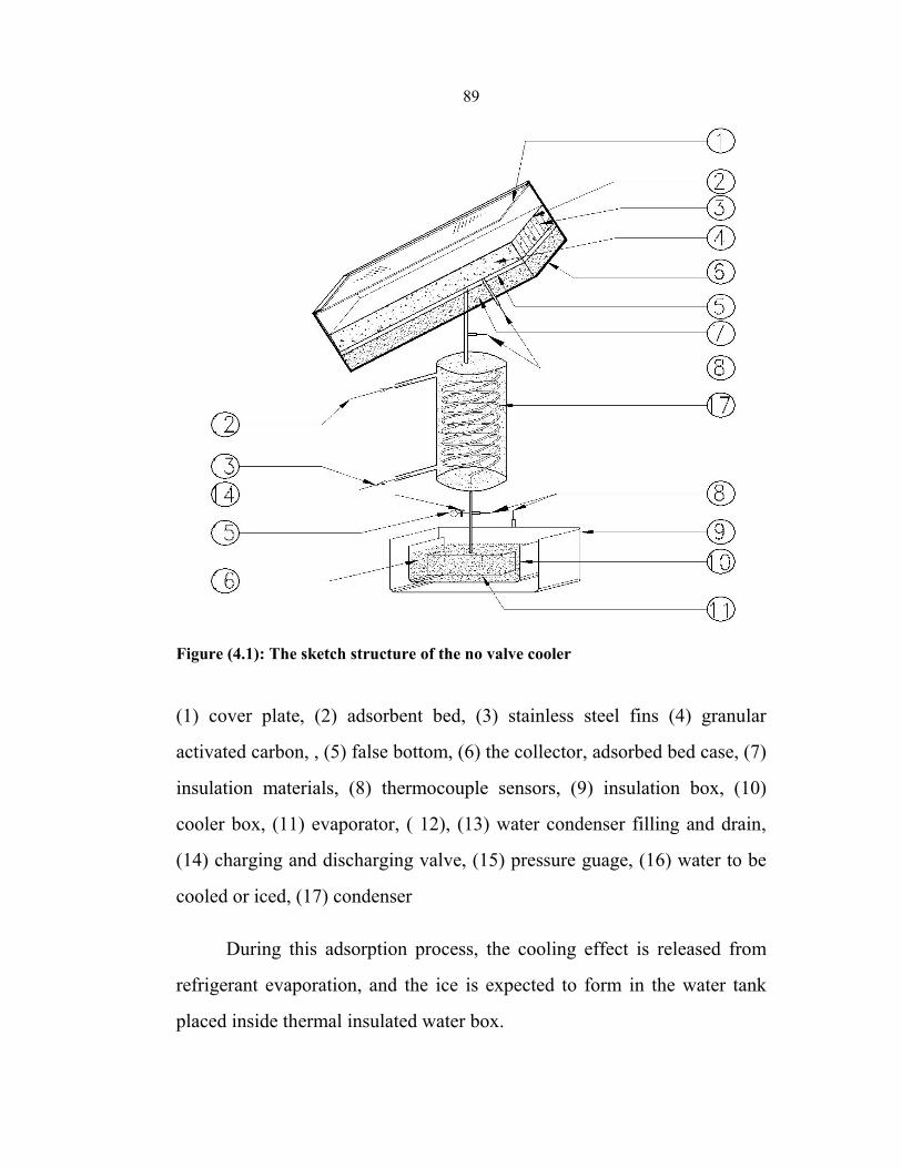
89
Figure (4.1): The sketch structure of the no valve cooler
(1) cover plate, (2) adsorbent bed, (3) stainless steel fins (4) granular
activated carbon, , (5) false bottom, (6) the collector, adsorbed bed case, (7)
insulation materials, (8) thermocouple sensors, (9) insulation box, (10)
cooler box, (11) evaporator, ( 12), (13) water condenser filling and drain,
(14) charging and discharging valve, (15) pressure guage, (16) water to be
cooled or iced, (17) condenser
During this adsorption process, the cooling effect is released from
refrigerant evaporation, and the ice is expected to form in the water tank
placed inside thermal insulated water box.
90
In general, the performance of solar ice maker are represented in
terms of Qref (or ice mass gotten in water tank) and the performance
efficiency COPsolar. They can be expressed as follows [ 50] :
Qref =∆xMaL (4.1)
∆ x = xconc _ xdil (4.2)
where xconc is the adsorption capacity before desorption, xdil is the
adsorption capacity after desorption, Ma is the mass of adsorbent inside
adsorbent bed, L is the latent heat of vaporization.
COPsolar = ( Qref – Qcc )/ ∫ i(t)dt (4.3)
where Qcc = ∫ Ma∆xCpl dT is the energy used to cool down the refrigerant
liquid from condensing temperature Tc to evaporation temperature Te, cp;
specific heat of refrigerant, ∫ i(t)dt, is the total radiant energy absorbed by
the collector during one day operation[50].
4.2 Construction of No Valve Solar cooler
4.2.1 Adsorbent Bed
Adsorbent bed is the most important part of the solar cooler, it is the
heart of solid adsorption refrigeration, and the characteristics of the
adsorbent bed are the most obvious factors which directly affect solid
adsorption systems. For the flat-plate solar cooler, the collector and
adsorbent bed are often designed into an integrated shape to enhance heat
transfer.
91
At the same time, several fins are also necessary to enhance heat
transfer, so that the heat received by the adsorbent bed top surface can be
quickly transferred inside the bed. Usually, this type of adsorbent bed
possesses good heat transfer ability [51]. Generally speaking, a good
adsorbent bed must have good heat and mass transfer. Recent research
showed that the aluminum alloy have a stronger catalytic effect on the
decomposition reaction under the solar adsorption refrigeration, therefore
stainless steel are used as adsorbent heat transfer metal instead of
aluminum alloy although stainless steel has poor heat transfer ability than
that of aluminum alloy[50].
The adsorbent bed is made of flat plate stainless steel box, having
surface area of nearly1 m2, also about 20 kg adsorbent (activated carbon) is
charged and sealed inside the steel plate box, then selective coating is
covered on top surface of the steel plate box to enhance receiving solar flux
radiation. Except for the top surface, every side of the adsorbent bed is
covered in insulation material ( insulated case).
On the top of the adsorbent bed, a glass cover is necessary to form a
“greenhouse” for the adsorbent bed, the sketch of the cross section of the
adsorbent bed shown in figure 4.2. However, in the evening, a moveable
damper may be installed to effectively cool the adsorbent bed by air. As
mentioned previously, in order to guarantee better heat transfer between the
front side and the adsorbent, many fins (also made of stainless steel) are
placed inside the adsorbent bed box in contact with the front side and the
activated carbon. The distance between these fins is approximately 0.05 m.
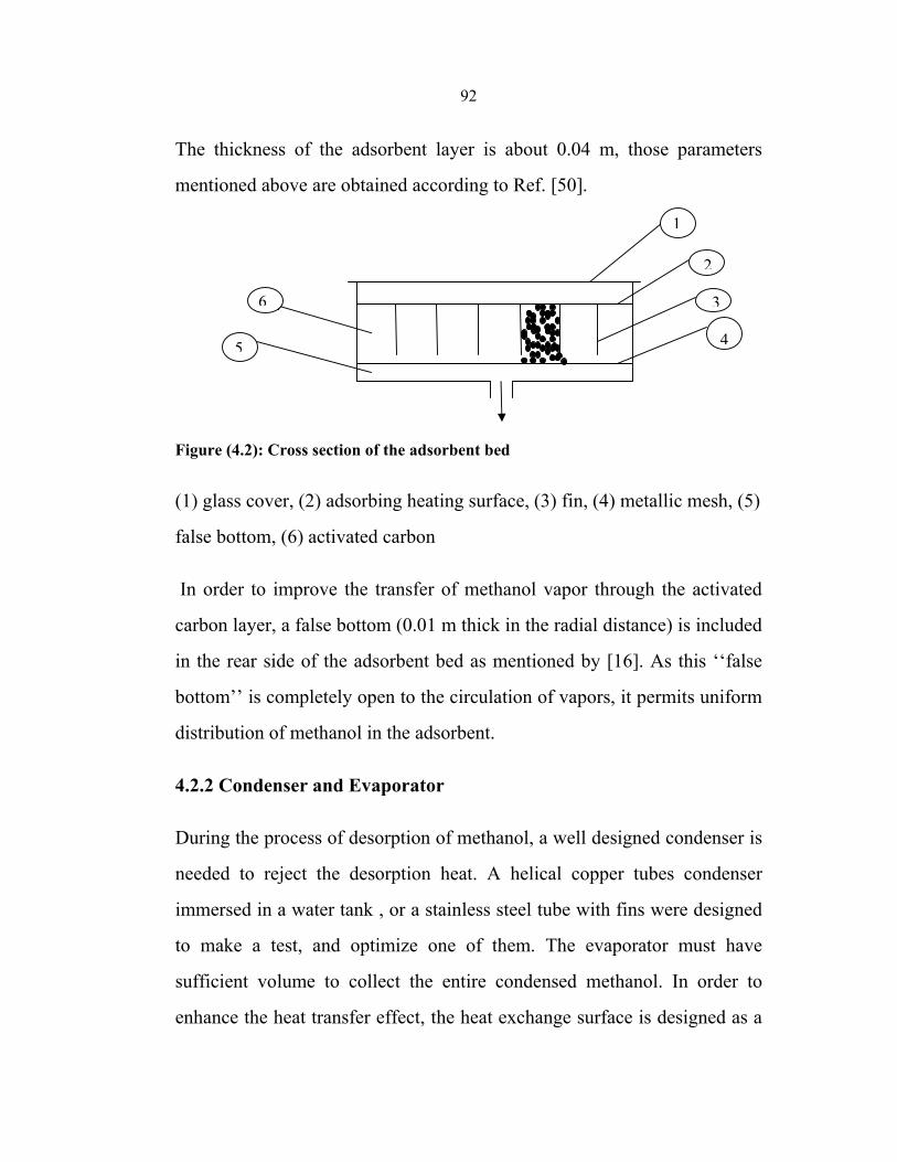
92
The thickness of the adsorbent layer is about 0.04 m, those parameters
mentioned above are obtained according to Ref. [50].
Figure (4.2): Cross section of the adsorbent bed
(1) glass cover, (2) adsorbing heating surface, (3) fin, (4) metallic mesh, (5)
false bottom, (6) activated carbon
In order to improve the transfer of methanol vapor through the activated
carbon layer, a false bottom (0.01 m thick in the radial distance) is included
in the rear side of the adsorbent bed as mentioned by [16]. As this ‘‘false
bottom’’ is completely open to the circulation of vapors, it permits uniform
distribution of methanol in the adsorbent.
4.2.2 Condenser and Evaporator
During the process of desorption of methanol, a well designed condenser is
needed to reject the desorption heat. A helical copper tubes condenser
immersed in a water tank , or a stainless steel tube with fins were designed
to make a test, and optimize one of them. The evaporator must have
sufficient volume to collect the entire condensed methanol. In order to
enhance the heat transfer effect, the heat exchange surface is designed as a
1
2
3
45
6
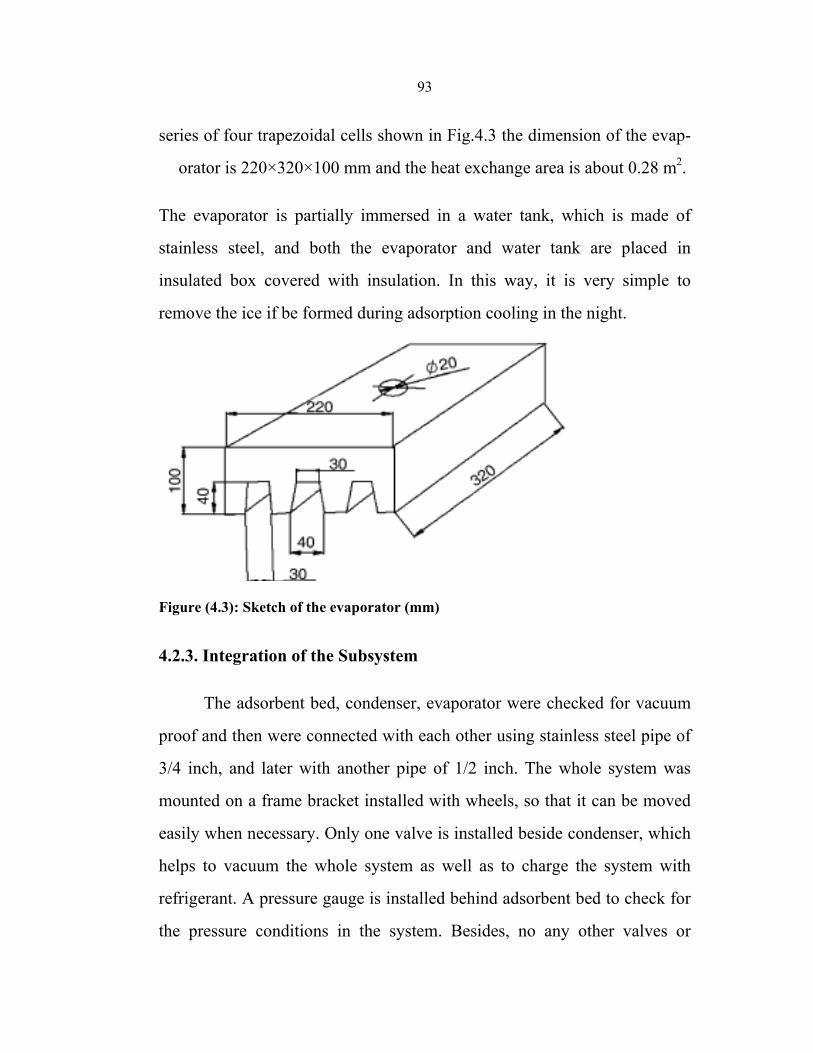
93
series of four trapezoidal cells shown in Fig.4.3 the dimension of the evap-
orator is 220×320×100 mm and the heat exchange area is about 0.28 m2.
The evaporator is partially immersed in a water tank, which is made of
stainless steel, and both the evaporator and water tank are placed in
insulated box covered with insulation. In this way, it is very simple to
remove the ice if be formed during adsorption cooling in the night.
Figure (4.3): Sketch of the evaporator (mm)
4.2.3. Integration of the Subsystem
The adsorbent bed, condenser, evaporator were checked for vacuum
proof and then were connected with each other using stainless steel pipe of
3/4 inch, and later with another pipe of 1/2 inch. The whole system was
mounted on a frame bracket installed with wheels, so that it can be moved
easily when necessary. Only one valve is installed beside condenser, which
helps to vacuum the whole system as well as to charge the system with
refrigerant. A pressure gauge is installed behind adsorbent bed to check for
the pressure conditions in the system. Besides, no any other valves or
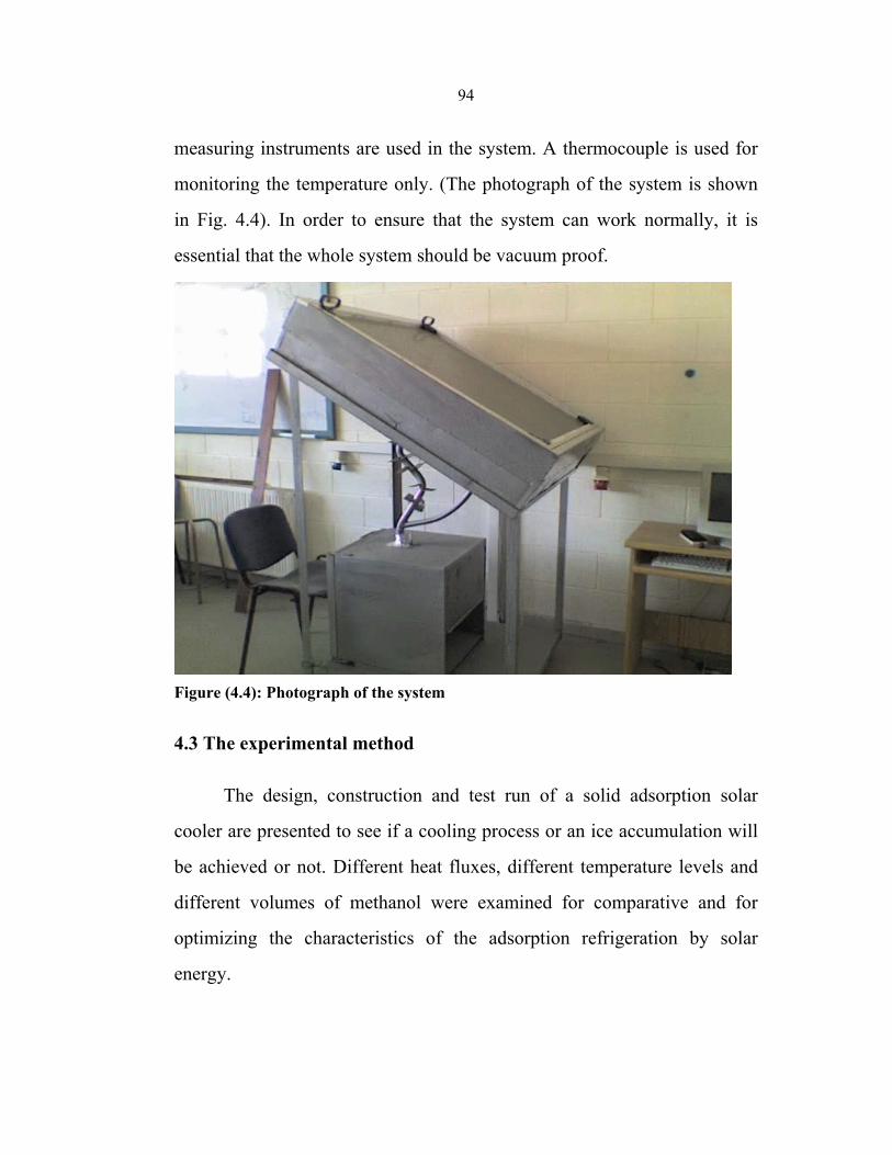
94
measuring instruments are used in the system. A thermocouple is used for
monitoring the temperature only. (The photograph of the system is shown
in Fig. 4.4). In order to ensure that the system can work normally, it is
essential that the whole system should be vacuum proof.
Figure (4.4): Photograph of the system
4.3 The experimental method
The design, construction and test run of a solid adsorption solar
cooler are presented to see if a cooling process or an ice accumulation will
be achieved or not. Different heat fluxes, different temperature levels and
different volumes of methanol were examined for comparative and for
optimizing the characteristics of the adsorption refrigeration by solar
energy.
95
Experiments for two types of condensers were made as mentioned
previously, the first one was made by using a helical copper pipe immersed
in a water tank, and the other was made by using an air-finned condenser.
The affinity of different particle size of activated carbon to methanol was
tested in the laboratory scale experiment.
After the construction of the system with water condenser, several
tests were performed to ensure good sealing, since any kind of air leakage
inside the system will lead to failure in the process, since such system work
under vacuum. The total pressure may increase due to leaks or desorption
of air from activated carbon, then the adsorption of methanol is reduced.
Furthermore, the boiling temperature of the methanol increases and the rate
of evaporation decreases, and as a result the cooling effect decreases. The
first experimental setup was designed with movable lids. But due to
difficulties in controlling the leakage, the system was completely sealed by
special stainless steel welding.
4.3.1 Methanol Charging and Heating Process
After the system was sealed, it was evacuated side by side with heating to
flush out entrapped air and moisture using a vacuum pump until the
pressure in the system decreased to 30 kPa. This was also used to test the
system for any leakage. Many attempts were done to overcome the leakage
problem, and the system was left for sufficient time for leakage monitoring.
These experiments divided to two steps :
96
Step 1:
The first experiment was done on the 23rd of July in 2007, at 11:30
o’clock. The system was evacuated to 50kPa, then the system was charged
with 2L of methanol, and the condenser tank was filled with 17 liter of
water and the cooler box with 5 liter of water.
As the solar heat flux density is taken from the solar source in
Palestine, and the total radiant energy to the collector is assumed to be
ƒG(t)dt = 20 MJ/m2 /day which is about 5.4 kWh/m2/day, electrical heater
with regulator was used to simulate solar heating. For the solar collector, an
average accepted radiation power of 770 W/m2during 7 hours is assumed,
thus; a 770 W electrical heater can simulate a squared meter flat plate solar
collector. This done by a potential regulator. Many parameters such as the
temperature of the adsorbent inside the generator, the temperature of
methanol at different points, condenser water temperature, room
temperature, water temperature inside the cooling box and the standing
pressure were monitored and recorded. The temperatures were measured by
thermocouples placed in the system, ( point 6 in Figure 4.1).
In the electric heating case, many experiments done to make sure
that the system operated normally without significant problems such as
leakage. The output data indicated as shown in Tables ( 4. 1 ) and (4.2 ).
Where:
T1: the temperature inside the adsorbent bed.
T2: the temperature at the inlet of the condenser.
97
T3: the temperature at the outlet of the condenser.
T4: the temperature inside the evaporator.
Twev: Temperature of the water inside the cooler box.
Tamb : Ambient temperature .
Tw,cond : temperature of the condenser water .
Pev : the pressure at the inlet of evaporator .
Pcond : the pressure at the inlet of condenser .
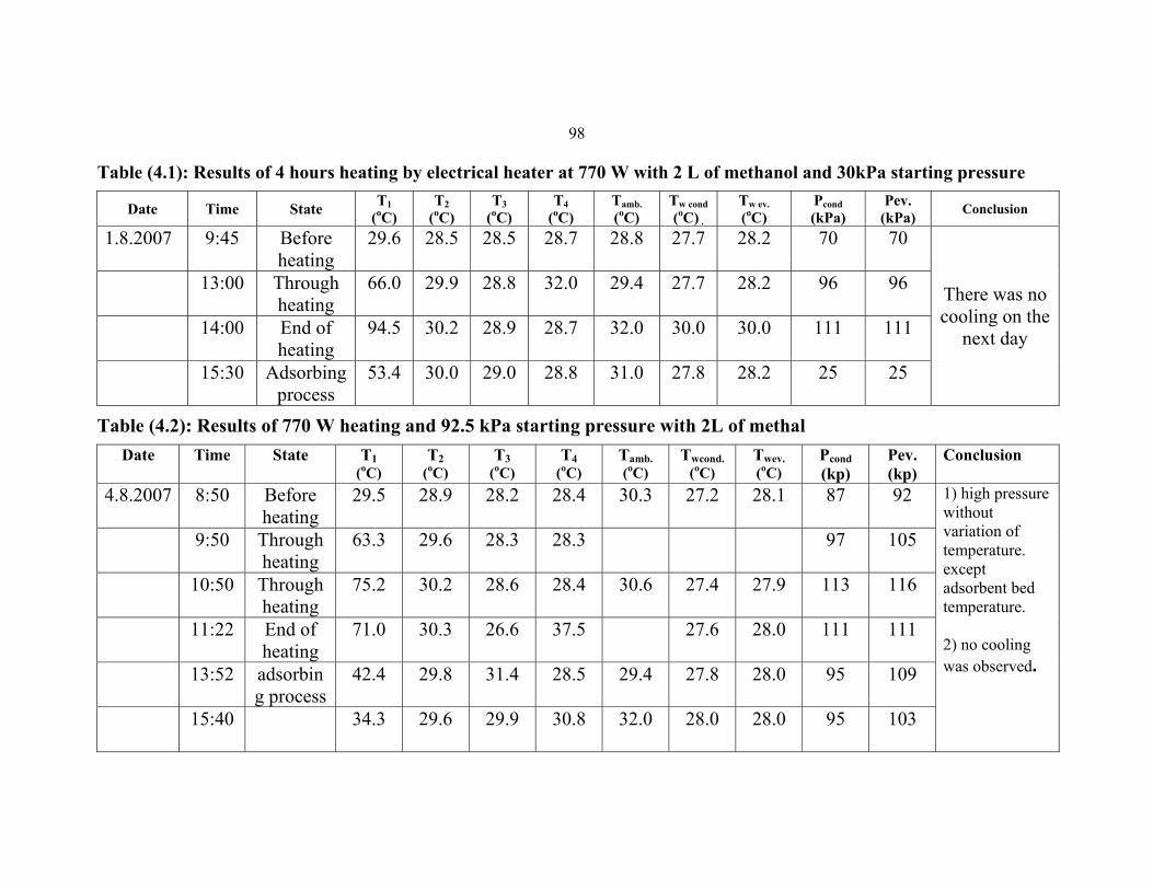
98
Table (4.1): Results of 4 hours heating by electrical heater at 770 W with 2 L of methanol and 30kPa starting pressure
Conclusion Pev.
(kPa)Pcond (kPa)
Tw ev. (oC)
Tw cond (oC) .
Tamb. (oC)
T4 (oC)
T3 (oC)
T2 (oC)
T1 (oC)State Time Date
There was no cooling on the
next day
70 70 28.2 27.7 28.8 28.7 28.5 28.5 29.6 Before heating
9:45 1.8.2007
96 96 28.2 27.7 29.4 32.0 28.8 29.9 66.0 Through heating
13:00
111 111 30.0 30.0 32.0 28.7 28.9 30.2 94.5 End of heating
14:00
25 25 28.2 27.8 31.0 28.8 29.0 30.0 53.4 Adsorbing process
15:30
Table (4.2): Results of 770 W heating and 92.5 kPa starting pressure with 2L of methal Date Time State T1
(oC)
T2 (oC)
T3 (oC)
T4 (oC)
Tamb. (oC)
Twcond. (oC)
Twev. (oC)
Pcond (kp)
Pev. (kp)
Conclusion
4.8.2007 8:50 Before heating
29.5 28.9 28.2 28.4 30.3 27.2 28.1 87 92 1) high pressure without variation of temperature. except adsorbent bed temperature.
2) no cooling was observed.
9:50 Through heating
63.3 29.6 28.3 28.3 97 105
10:50 Through heating
75.2 30.2 28.6 28.4 30.6 27.4 27.9 113 116
11:22 End of heating
71.0 30.3 26.6 37.5 27.6 28.0 111 111
13:52 adsorbing process
42.4 29.8 31.4 28.5 29.4 27.8 28.0 95 109
15:40 34.3 29.6 29.9 30.8 32.0 28.0 28.0 95 103
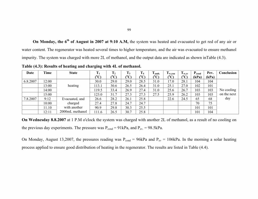
99
On Monday, the 6th of August in 2007 at 9:10 A.M, the system was heated and evacuated to get red of any air or
water content. The regenerator was heated several times to higher temperature, and the air was evacuated to ensure methanol
impurity. The system was charged with more 2L of methanol, and the output data are indicated as shown inTable (4.3).
Table (4.3): Results of heating and charging with 4L of methanol. Conclusion Pev.
(kPa) Pcond (kPa)
Tw,ev (oC)
Tw,con (oC)
Tamb. (oC)
T4 (oC)
T3 (oC)
T2 (oC)
T1 (oC)
State Time Date
No cooling on the next
day
104 104 28.1 17.0 31.0 28.5 29.0 29.0 30.0 heating
12:00 6.8.2007101 102 27.0 25.1 31.0 26.4 26.5 30.6 113.1 13:00 103 103 26.7 25.6 31.0 27.4 26.9 33.4 119.5 14:00 103 103 26.2 25.9 27.5 27.3 27.3 31.7 123.0 15:00 68 65 24.5 22.6 25.8 26.1 28.2 26.6 Evacuated, and
charged with another
2000mL methanol
9:12 7.8.200775 70 24.7 24.7 27.8 27.4 10:00 101 101 25.5 30.3 29.8 90.9 11.10 104 101 25.8 30.7 26.5 111.6 12:11
On Wednesday 8.8.2007 at 1 P.M o'clock the system was charged with another 2L of methanol, as a result of no cooling on
the previous day experiments. The pressure was Pcond = 91kPa, and Pev. = 98.5kPa.
On Monday, August 13,2007, the pressures reading was Pcond = 96kPa and Pev = 106kPa. In the morning a solar heating
process applied to ensure good distribution of heating in the regenerator. The results are listed in Table (4.4).
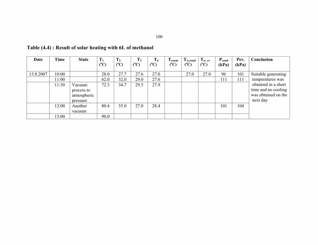
100
Table (4.4) : Result of solar heating with 6L of methanol
Conclusion Pev. (kPa)
Pcond (kPa)
Tw, ev (oC)
Tw,cond (oC)
Troom (oC)
T4 (oC)
T3 (oC)
T2 (oC)
T1 (oC)
State Time Date
Suitable generating temperatures was obtained in a short time and no cooling was obtained on the next day
1019627.027.027.027.627.728.0 10:00 13.8.2007111 111 27.6 29.0 32.0 62.0 11:00 27.9 29.5 34.7 72.3 Vacuum
process to atmospheric pressure
11:30
104 101 28.4 27.0 35.0 80.4 Another vacuum
12:00
90.0 13:00
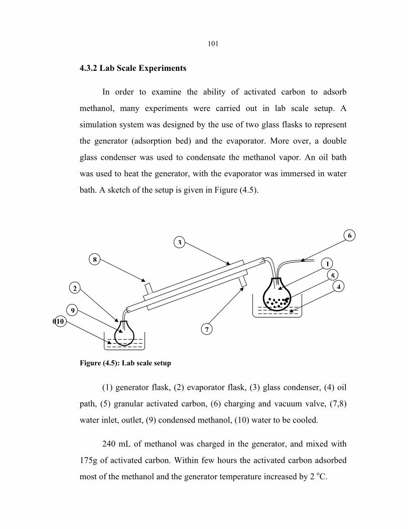
101
4.3.2 Lab Scale Experiments
In order to examine the ability of activated carbon to adsorb
methanol, many experiments were carried out in lab scale setup. A
simulation system was designed by the use of two glass flasks to represent
the generator (adsorption bed) and the evaporator. More over, a double
glass condenser was used to condensate the methanol vapor. An oil bath
was used to heat the generator, with the evaporator was immersed in water
bath. A sketch of the setup is given in Figure (4.5).
Figure (4.5): Lab scale setup
(1) generator flask, (2) evaporator flask, (3) glass condenser, (4) oil
path, (5) granular activated carbon, (6) charging and vacuum valve, (7,8)
water inlet, outlet, (9) condensed methanol, (10) water to be cooled.
240 mL of methanol was charged in the generator, and mixed with
175g of activated carbon. Within few hours the activated carbon adsorbed
most of the methanol and the generator temperature increased by 2 oC.
100
2
9
8
36
15
4
7
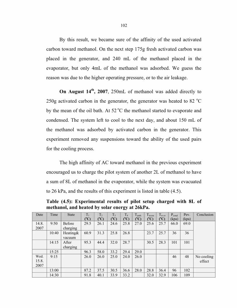
102
By this result, we became sure of the affinity of the used activated
carbon toward methanol. On the next step 175g fresh activated carbon was
placed in the generator, and 240 mL of the methanol placed in the
evaporator, but only 4mL of the methanol was adsorbed. We guess the
reason was due to the higher operating pressure, or to the air leakage.
On August 14th, 2007, 250mL of methanol was added directly to
250g activated carbon in the generator, the generator was heated to 82 oC
by the mean of the oil bath. At 52 oC the methanol started to evaporate and
condensed. The system left to cool to the next day, and about 150 mL of
the methanol was adsorbed by activated carbon in the generator. This
experiment removed any suspensions toward the ability of the used pairs
for the cooling process.
The high affinity of AC toward methanol in the previous experiment
encouraged us to charge the pilot system of another 2L of methanol to have
a sum of 8L of methanol in the evaporator, while the system was evacuated
to 26 kPa, and the results of this experiment is listed in table (4.5).
Table (4.5): Experimental results of pilot setup charged with 8L of methanol, and heated by solar energy at 26kPa.
Date Time State T1 (oC)
T2 (oC)
T3 (oC)
T4 (oC)
Tamb. (oC)
Twcon (oC)
Tw ev (oC).
Pcond (kpa)
Pev. (kpa)
Conclusion
14.8. 2007
9:50 Before charging
29.5 26.1 24.6 25.8 27.0 25.6 25.7 66.0 69.0
10:40 Heating& vacuum
60.9 31.3 25.8 26.8 23.7 25.7 36 36
14:15 After charging
95.3 44.4 32.0 28.7 30.5 28.3 101 101
15:25 96.3 58.0 33.2 29.4 29.0 Wed. 15.8. 2007
9:15 26.0 26.0 25.0 24.0 26.0 46 48 No cooling effect
13:00 87.2 37.5 30.5 36.6 28.0 28.8 36.4 96 102 14:30 91.8 40.1 33.9 33.2 32.0 32.9 106 109
103
On Wednesday 15.8.2007, small quantity of methanol was found in
the evaporator, which means that the desorption process had occurred and
the charged quantity of methanol is larger than that of AC capacity of
adsorption. The evaporator was heated in hot water bath in order to
evaporate the methanol, the pressure increased to Pcond = 49kPa, and Pev=
53.5kPa. Despite this heating process a quantity of methanol remained in
the evaporator, and this can be explained by the fact that activated carbon
had reached its saturation capacity.
Another experiment was done with the Lab scale setup where 150mL
of methanol was mixed with 220g of activated carbon in the flask
representing the generator. The generator was heated with water bath, and
the desorption process started when the temperature of hot water reached
52oC. The condensing process started 20 minute later. When the
temperature of hot water reached 85oC, the heating process was stopped but
the methanol in the evaporator didn't adsorbed back by AC in the generator
and no significant cooling was observed.
To study the influence of the operating pressure at the performance
of the system another experiment was done with the lab scale setup, where
80 ml of methanol was charged into the evaporator flask and a heating
process at atmospheric pressure was applied to the generator flask to get rid
of any methanol within the activated carbon. The desorption process started
also at 52 oC. When the temperature of hot water reached 95 oC the heating
process was stopped. The highest desorption quantity was occurred when
the temperature of heating water was 80 oC to 90 oC. The system left to cool
gradually, and the result was neither adsorption process nor cooling.
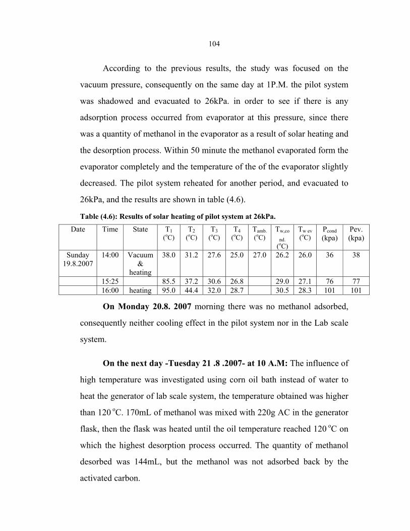
104
According to the previous results, the study was focused on the
vacuum pressure, consequently on the same day at 1P.M. the pilot system
was shadowed and evacuated to 26kPa. in order to see if there is any
adsorption process occurred from evaporator at this pressure, since there
was a quantity of methanol in the evaporator as a result of solar heating and
the desorption process. Within 50 minute the methanol evaporated form the
evaporator completely and the temperature of the of the evaporator slightly
decreased. The pilot system reheated for another period, and evacuated to
26kPa, and the results are shown in table (4.6).
Table (4.6): Results of solar heating of pilot system at 26kPa.
Date Time State T1 (oC)
T2 (oC)
T3 (oC)
T4 (oC)
Tamb. (oC)
Tw,co
nd. (oC)
Tw ev (oC)
Pcond (kpa)
Pev. (kpa)
Sunday 19.8.2007
14:00 Vacuum &
heating
38.0 31.2 27.6 25.0 27.0 26.2 26.0 36 38
15:25 85.5 37.2 30.6 26.8 29.0 27.1 76 77 16:00 heating 95.0 44.4 32.0 28.7 30.5 28.3 101 101
On Monday 20.8. 2007 morning there was no methanol adsorbed,
consequently neither cooling effect in the pilot system nor in the Lab scale
system.
On the next day -Tuesday 21 .8 .2007- at 10 A.M: The influence of
high temperature was investigated using corn oil bath instead of water to
heat the generator of lab scale system, the temperature obtained was higher
than 120 oC. 170mL of methanol was mixed with 220g AC in the generator
flask, then the flask was heated until the oil temperature reached 120 oC on
which the highest desorption process occurred. The quantity of methanol
desorbed was 144mL, but the methanol was not adsorbed back by the
activated carbon.
105
In order to examine the ability of activated carbon for methanol
adsorption under a deep evacuation process, a volume of 50mL of
methanol was placed in the flask representing evaporator and a quantity of
100g of AC was placed in the flask representing the generator. The
adsorption process occurred resulting in a temperature drop of 16 oC.
Another experiment was done to examine the adsorption ability of
two particle size (granular and powder) of activated carbon. 10g of each
size was placed in a beaker, and placed near another beaker contains 80mL
of methanol in a vacuum oven. The oven was evacuated to 10kPa. On the
next day, the granular activated carbon weight increased by 2.8g, while the
powder increased by 1.9g, on the other hand the methanol volume
decreased by 12.8mL.
Another experiment was done in order to examine the ability of
activated carbon for methanol adsorption. In this experiment 20g of fresh
AC was charged in the flask representing the generator, while 15mL of
methanol poured in the flask representing the evaporator. The system was
evacuated to the boiling pressure of methanol at room temperature (30oC).
After the evacuation process, the methanol started to evaporate and was
adsorbed by the activated carbon resulting a cooling effect at the surface of
the evaporator, while the temperature was increased at the surface of the
generator, but after a while the process was slow down due to the
increasing of pressure inside the system as a result of none perfect sealing.
This experiment is a good indicator of the importance of keeping the
system sealed and at low pressure as possible.
106
In order to examine the effect of evaporator volume, another
experiment was performed using the lab scale setup. In this experiment the
condenser was shortened and smaller volume of evaporator was used.
45g of fresh activated carbon was placed in the generator flask, while
20mL of methanol was placed in the evaporator flask. After making the
required evacuation process, the methanol evaporation was observed, and
adsorbed by the activated carbon. The temperature of the evaporator
decreased from 29.6 oC to 27.8 oC within 2 hours. The cooling process was
observed during 3 hours and all the time the cooling effect existed.
On the next day the volume of methanol in the evaporator decreased
by 8mL whiles the weight of AC increased by 11.6 g.
These results encouraged examining the influence of the quantity of
activated carbon on the adsorption process, therefore, 60g of granular
activated carbon and 22mL of methanol were placed in the generator flask
and the evaporator flask respectively. After evacuation process, a low
temperature was obtained on the surface of the evaporator. The
temperatures were: Tev.= 15.5oc, Tgen= 34oc and Tamb.= 30.4oc, and after 5
minutes the temperatures were 15.7, 35.2 and 31oc respectively.
The cooling effect continued for four hours, and evaporating process
was still occurring.
According to these results one can calculate the adsorption capacity
of the used activated carbon as:
AC adsorption capacity =
107
Mass of methanol = volume ×density = 0.787× 22 g/ mL
Mass of AC = 60g
Then, the adsorption capacity of AC is :
22× 0.787/ 60 = 0.29 kg methanol/kg AC
This value is less than the value that some researchers indicated [27].
From the previous experiments we could conclude that the adsorption –
desorption cycle had been achieved.
4.3.3 Conclusions
After the previous experiments, some conclusions were reached:
1) The adsorption bed has the greatest effect on the performance and the
characteristics of the solar cooler. It must be well manufactured, well
sealed and well controlled; as a result, another type of generator may be
used such as two coaxial pipes.
2) In low pressure systems, the condenser and the evaporator must be close
to each other and to the collector. Thus, they should be located directly
under the generator such that the refrigerant flows into them by gravity. As
a result the condenser in the pilot scale setup should be replaced by a pipe
condenser.
3) Both of the size and shape of the evaporator must be optimized, it have
to be sized to suit the amount of the methanol, as a result of lab scale
experiments.
108
4) The generator (adsorbent bed) must be positioned not far from the
evaporator in order to ensure high pressure of methanol vapor and good
distribution of vapor.
5) The size and the shape of condenser must be optimized, as a result of lab
scale experiments.
6) Desorption process started from 52 to 58oC. when the operating pressure
was the boiling pressure of methanol at room temperature (30 oC).
7) The system must manufactured in an integrated manner.
8) The activated carbon must be heated over 80 oC under a deep vacuum
pressure, in order to enhance the desorption of methanol.
9) The vacuum pressure has the greatest effect on the system operation.
The pressure must be less than 20kPa. Therefore to modify pressure in the
solar pilot system the following modifications are proposed:
a) A new type of pipe condenser must be used, pressure resistant collector
frame can be used, and high quality and larger size connecting pipe should
be used.
b) Design of another collector/ generator consist of several coaxial pipes in
which the inner tubes were perforated axially and circumferential. Each
annular space between the inner and outer tube charged with activated
carbon. The schematic diagram of this design is shown in figure (4.6 ).
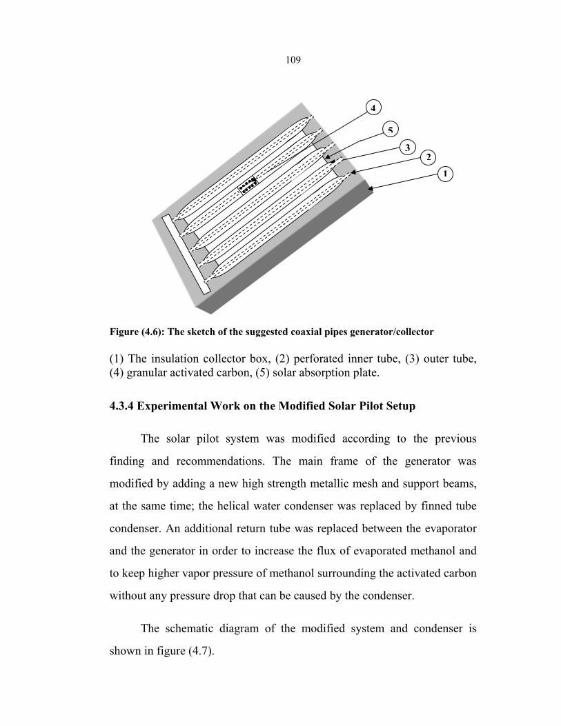
109
Figure (4.6): The sketch of the suggested coaxial pipes generator/collector (1) The insulation collector box, (2) perforated inner tube, (3) outer tube, (4) granular activated carbon, (5) solar absorption plate.
4.3.4 Experimental Work on the Modified Solar Pilot Setup
The solar pilot system was modified according to the previous
finding and recommendations. The main frame of the generator was
modified by adding a new high strength metallic mesh and support beams,
at the same time; the helical water condenser was replaced by finned tube
condenser. An additional return tube was replaced between the evaporator
and the generator in order to increase the flux of evaporated methanol and
to keep higher vapor pressure of methanol surrounding the activated carbon
without any pressure drop that can be caused by the condenser.
The schematic diagram of the modified system and condenser is
shown in figure (4.7).
4
5
32
1
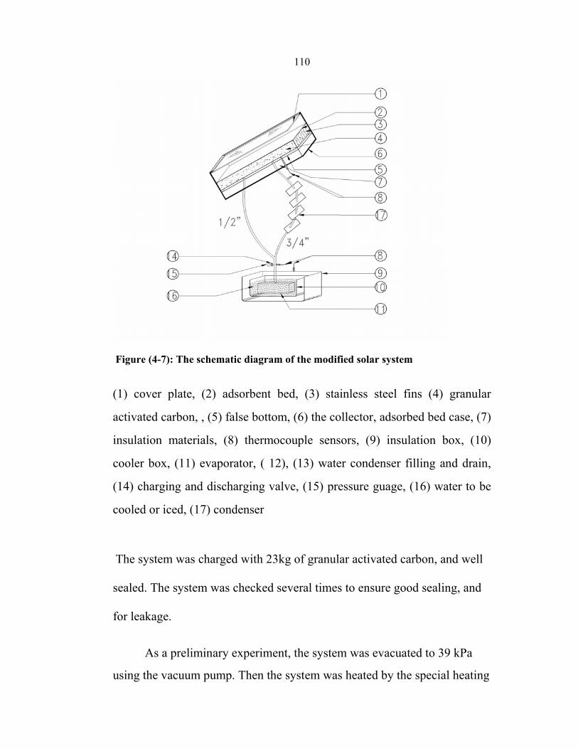
110
Figure (4-7): The schematic diagram of the modified solar system
(1) cover plate, (2) adsorbent bed, (3) stainless steel fins (4) granular
activated carbon, , (5) false bottom, (6) the collector, adsorbed bed case, (7)
insulation materials, (8) thermocouple sensors, (9) insulation box, (10)
cooler box, (11) evaporator, ( 12), (13) water condenser filling and drain,
(14) charging and discharging valve, (15) pressure guage, (16) water to be
cooled or iced, (17) condenser
The system was charged with 23kg of granular activated carbon, and well
sealed. The system was checked several times to ensure good sealing, and
for leakage.
As a preliminary experiment, the system was evacuated to 39 kPa
using the vacuum pump. Then the system was heated by the special heating
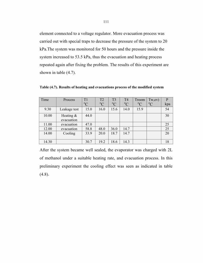
111
element connected to a voltage regulator. More evacuation process was
carried out with special traps to decrease the pressure of the system to 20
kPa.The system was monitored for 50 hours and the pressure inside the
system increased to 53.5 kPa, thus the evacuation and heating process
repeated again after fixing the problem. The results of this experiment are
shown in table (4.7).
Table (4.7). Results of heating and evacuations process of the modified system
P kpa
Tw,ev) oC
Troom oC
T4 oC
T3 oC
T2 oC
T1oC
Process Time
54 15.9 14.0 15.6 16.0 15.0 Leakage test 9.30
30 44.0 Heating & evacuation
10.00
25 47.0 evacuation 11.00 25 14.7 36.0 48.0 58.8 evacuation 12.00 20 14.7 18.7 20.0 33.9 Cooling 14.00
18 14.3 18.6 19.2 30.7 14.30
After the system became well sealed, the evaporator was charged with 2L
of methanol under a suitable heating rate, and evacuation process. In this
preliminary experiment the cooling effect was seen as indicated in table
(4.8).
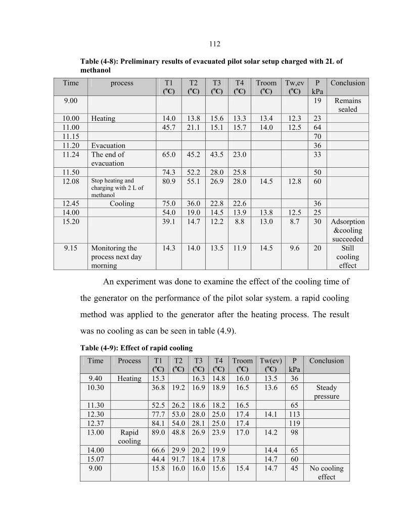
112
Table (4-8): Preliminary results of evacuated pilot solar setup charged with 2L of methanol
Conclusion P kPa
Tw,ev (oC)
Troom (oC)
T4 (oC)
T3 (oC)
T2 (oC)
T1 (oC)
process Time
Remains sealed
19 9.00
23 12.3 13.4 13.3 15.6 13.8 14.0 Heating 10.00 64 12.5 14.0 15.7 15.1 21.1 45.7 11.00 70 11.15 36 Evacuation 11.20 33 23.0 43.5 45.2 65.0 The end of
evacuation 11.24
50 25.8 28.0 52.2 74.3 11.50 60 12.8 14.5 28.0 26.9 55.1 80.9 Stop heating and
charging with 2 L of methanol
12.08
36 22.6 22.8 36.0 75.0 Cooling 12.45 25 12.5 13.8 13.9 14.5 19.0 54.0 14.00
Adsorption &cooling succeeded
30 8.7 13.0 8.8 12.2 14.7 39.1 15.20
Still cooling effect
20 9.6 14.5 11.9 13.5 14.0 14.3 Monitoring the process next day morning
9.15
An experiment was done to examine the effect of the cooling time of
the generator on the performance of the pilot solar system. a rapid cooling
method was applied to the generator after the heating process. The result
was no cooling as can be seen in table (4.9).
Table (4-9): Effect of rapid cooling
Conclusion P kPa
Tw(ev)(oC)
Troom(oC)
T4 (oC)
T3 (oC)
T2 (oC)
T1 (oC)
Process Time
36 13.5 16.0 14.816.3 15.3Heating 9.40 Steady
pressure 65 13.6 16.5 18.916.919.236.8 10.30
65 16.5 18.218.626.252.5 11.30 11314.1 17.4 25.028.053.077.7 12.30 11917.425.028.154.084.1 12.37 98 14.2 17.0 23.926.948.889.0Rapid
cooling 13.00
65 14.4 19.920.229.966.6 14.00 60 14.7 17.818.4 91.744.4 15.07
No cooling effect
45 14.7 15.4 15.616.016.015.8 9.00
113
Since the pressure increased to76 kPa again, it was concluded that
the solar system must be evacuated from time to time as needed .
In another preliminary experiment, the system was heated to 79 oC
and then evacuated to 41 kPa, and recharge with 2.5 L of methanol. The
system was re-evacuated again, when the temperature reached 96 oC.
The system recharged with another 1.25 L of methanol, and the
results of this experiment is given in table (4.10).
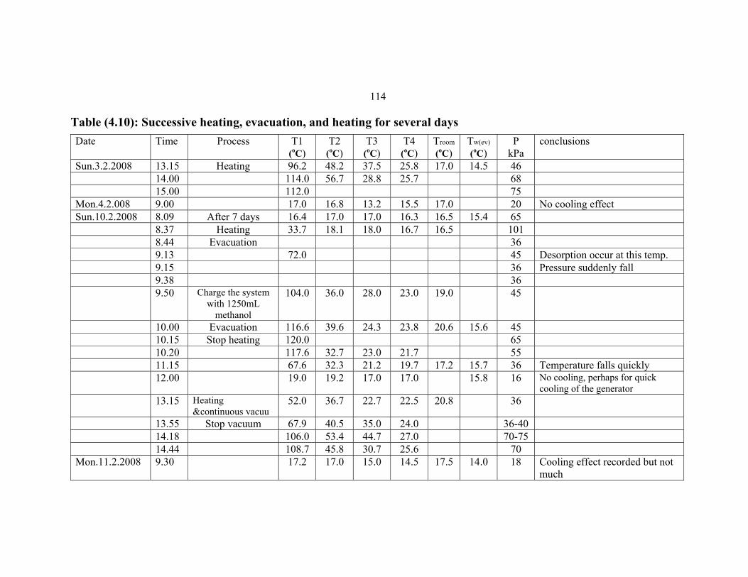
114
Table (4.10): Successive heating, evacuation, and heating for several days conclusionsP
kPa Tw(ev)
(oC)
Troom
(oC)
T4 (oC)
T3 (oC)
T2 (oC)
T1 (oC)
Process TimeDate
46 14.5 17.0 25.8 37.5 48.2 96.2 Heating 13.15Sun.3.2.200868 25.7 28.8 56.7 114.0 14.0075 112.0 15.00
No cooling effect20 17.0 15.5 13.2 16.8 17.0 9.00 Mon.4.2.00865 15.4 16.5 16.3 17.0 17.0 16.4 After 7 days 8.09Sun.10.2.2008101 16.5 16.7 18.0 18.1 33.7 Heating 8.3736 Evacuation 8.44
Desorption occur at this temp.45 72.0 9.13Pressure suddenly fall36 9.15
36 9.3845 19.0 23.0 28.0 36.0 104.0 Charge the system
with 1250mL methanol
9.50
45 15.6 20.6 23.8 24.3 39.6 116.6 Evacuation 10.0065 120.0 Stop heating 10.1555 21.7 23.0 32.7 117.6 10.20
Temperature falls quickly36 15.7 17.2 19.7 21.2 32.3 67.6 11.15No cooling, perhaps for quick cooling of the generator
16 15.8 17.0 17.0 19.2 19.0 12.00
36 20.8 22.5 22.7 36.7 52.0 Heating &continuous vacuu
13.15
36-40 24.0 35.0 40.5 67.9 Stop vacuum 13.55 70-75 27.0 44.7 53.4 106.0 14.18
70 25.6 30.7 45.8 108.7 14.44Cooling effect recorded but not much
18 14.0 17.5 14.5 15.0 17.0 17.2 9.30Mon.11.2.2008
115
As shown in table (4.10), the temperatures in the cooler box and in
the evaporator, after a day, were about 2 to 3 below room temperature, this
means that there was a cooling effect consequently an adsorption process
occurred at the previous night and day . The pressure in the system stayed
at 18kPa . The system was charged with 0.5 L of methanol .
On the next day the system was charged with another 0.5L of methanol to
improve the cooling effect obtained in the previous experiment. The
heating process was carried out side by side with a continuous evacuation
process .
The pressure stayed at 28 kPa, while the evaporator was empty of
any methanol which gives an indication that all methanol was adsorbed by
the activated carbon. The results are indicated in table (4.11).
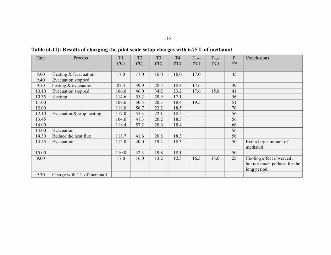
116
Table (4.11): Results of charging the pilot scale setup charges with 6.75 L of methanol Time Process T1
(oC) T2
(oC) T3
(oC) T4
(oC)
Troom (oC)
Tw,ev (oC)
P kPa
Conclusions
8.00 Heating & Evacuation 17.0 17.0 16.0 16.0 17.0 45 9.40 Evacuation stopped 9.50 heating & evacuation 87.4 39.9 28.5 18.3 17.6 39 10.10 Evacuation stopped 106.0 46.0 34.2 23.2 17.6 15.8 41 10.35 Heating 114.6 55.2 20.9 17.1 56 11.00 108.6 50.5 20.5 18.4 19.5 51 12.00 118.0 56.7 22.2 18.5 76 12.10 Evacuation& stop heating 117.0 55.3 22.1 18.5 56 13.45 104.6 41.3 20.2 18.3 56 14.00 118.4 57.2 20.6 18.4 66 14.00 Evacuation 56 14.30 Reduce the heat flux 118.7 41.6 20.8 18.3 56 14.45 Evacuation 112.0 40.0 19.4 18.3 50 Exit a large amount of
methanol 15.00 110.0 42.3 19.8 18.1 50 9.00 17.0 16.0 13.2 12.3 16.5 13.0 25 Cooling effect observed ,
but not much perhaps for the long period
9.30 Charge with 1 L of methanol
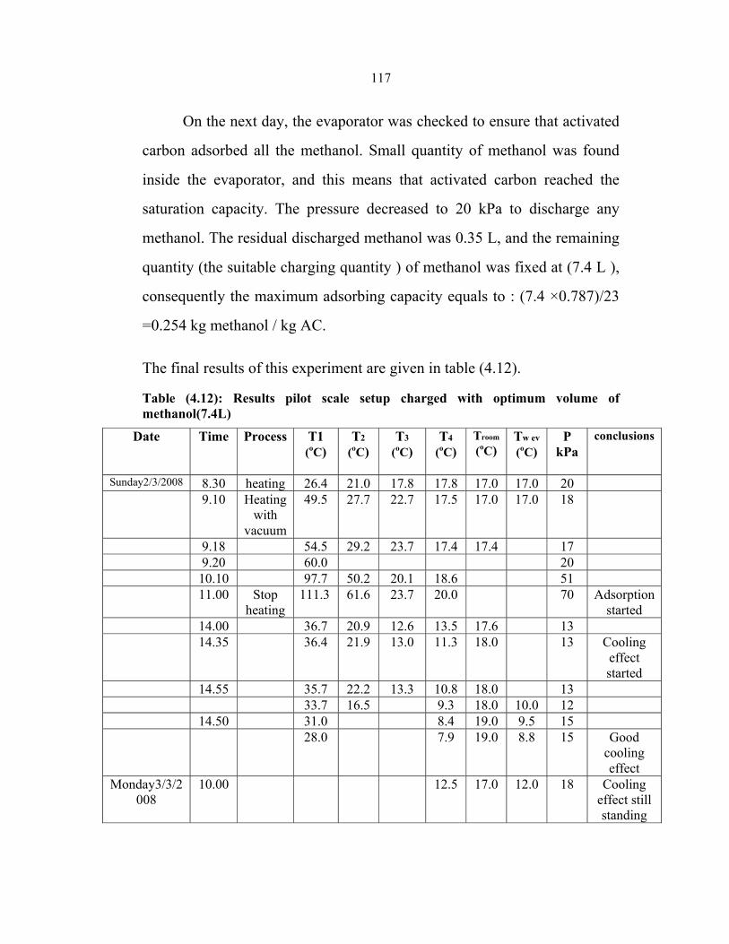
117
On the next day, the evaporator was checked to ensure that activated
carbon adsorbed all the methanol. Small quantity of methanol was found
inside the evaporator, and this means that activated carbon reached the
saturation capacity. The pressure decreased to 20 kPa to discharge any
methanol. The residual discharged methanol was 0.35 L, and the remaining
quantity (the suitable charging quantity ) of methanol was fixed at (7.4 L ),
consequently the maximum adsorbing capacity equals to : (7.4 ×0.787)/23
=0.254 kg methanol / kg AC.
The final results of this experiment are given in table (4.12).
Table (4.12): Results pilot scale setup charged with optimum volume of methanol(7.4L)
Date Time Process T1 (oC)
T2
(oC)
T3 (oC)
T4
(oC)
Troom
(oC)
Tw ev (oC)
P kPa
conclusions
Sunday2/3/2008 8.30 heating 26.4 21.0 17.8 17.8 17.0 17.0 20 9.10 Heating
with vacuum
49.5 27.7 22.7 17.5 17.0 17.0 18
9.18 54.5 29.2 23.7 17.4 17.4 17 9.20 60.0 20 10.10 97.7 50.2 20.1 18.6 51 11.00 Stop
heating 111.3 61.6 23.7 20.0 70 Adsorption
started 14.00 36.7 20.9 12.6 13.5 17.6 13 14.35 36.4 21.9 13.0 11.3 18.0 13 Cooling
effect started
14.55 35.7 22.2 13.3 10.8 18.0 13 33.7 16.5 9.3 18.0 10.0 12 14.50 31.0 8.4 19.0 9.5 15 28.0 7.9 19.0 8.8 15 Good
cooling effect
Monday3/3/2008
10.00 12.5 17.0 12.0 18 Cooling effect still standing
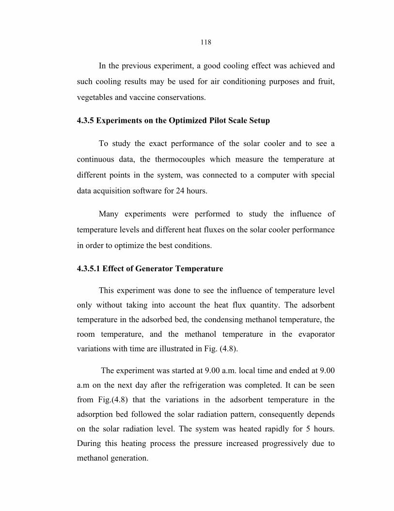
118
In the previous experiment, a good cooling effect was achieved and
such cooling results may be used for air conditioning purposes and fruit,
vegetables and vaccine conservations.
4.3.5 Experiments on the Optimized Pilot Scale Setup
To study the exact performance of the solar cooler and to see a
continuous data, the thermocouples which measure the temperature at
different points in the system, was connected to a computer with special
data acquisition software for 24 hours.
Many experiments were performed to study the influence of
temperature levels and different heat fluxes on the solar cooler performance
in order to optimize the best conditions.
4.3.5.1 Effect of Generator Temperature
This experiment was done to see the influence of temperature level
only without taking into account the heat flux quantity. The adsorbent
temperature in the adsorbed bed, the condensing methanol temperature, the
room temperature, and the methanol temperature in the evaporator
variations with time are illustrated in Fig. (4.8).
The experiment was started at 9.00 a.m. local time and ended at 9.00
a.m on the next day after the refrigeration was completed. It can be seen
from Fig.(4.8) that the variations in the adsorbent temperature in the
adsorption bed followed the solar radiation pattern, consequently depends
on the solar radiation level. The system was heated rapidly for 5 hours.
During this heating process the pressure increased progressively due to
methanol generation.
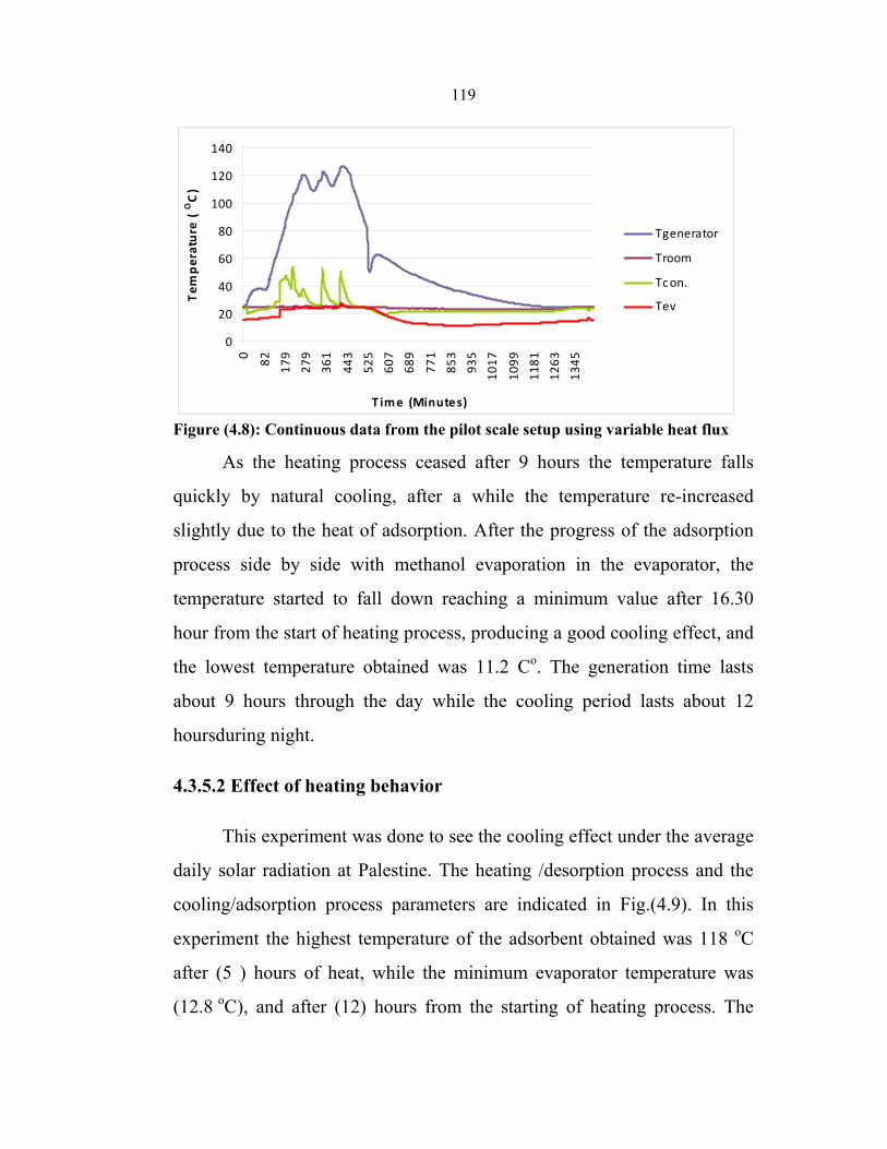
119
0
20
40
60
80
100
120
140
0 82 179
279
361
443
525
607
689
771
853
935
1017
1099
1181
1263
1345
T ime (Minutes)
Tem
perature (
OC)
Tgenerator
Troom
Tcon.
Tev
Figure (4.8): Continuous data from the pilot scale setup using variable heat flux
As the heating process ceased after 9 hours the temperature falls
quickly by natural cooling, after a while the temperature re-increased
slightly due to the heat of adsorption. After the progress of the adsorption
process side by side with methanol evaporation in the evaporator, the
temperature started to fall down reaching a minimum value after 16.30
hour from the start of heating process, producing a good cooling effect, and
the lowest temperature obtained was 11.2 Cο. The generation time lasts
about 9 hours through the day while the cooling period lasts about 12
hoursduring night.
4.3.5.2 Effect of heating behavior
This experiment was done to see the cooling effect under the average
daily solar radiation at Palestine. The heating /desorption process and the
cooling/adsorption process parameters are indicated in Fig.(4.9). In this
experiment the highest temperature of the adsorbent obtained was 118 οC
after (5 ) hours of heat, while the minimum evaporator temperature was
(12.8 οC), and after (12) hours from the starting of heating process. The
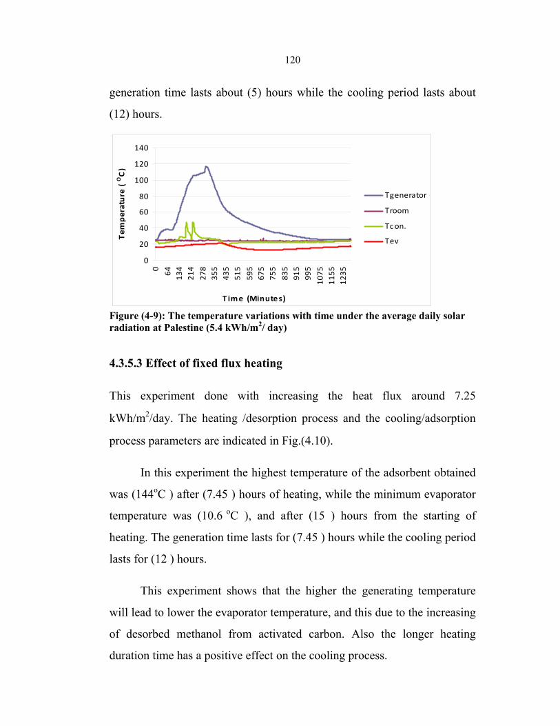
120
generation time lasts about (5) hours while the cooling period lasts about
(12) hours.
0
20
40
60
80
100
120
1400 64 134
214
278
355
435
515
595
675
755
835
915
995
1075
1155
1235
T ime (Minutes)
Tem
perature (
OC)
Tgenerator
Troom
Tcon.
Tev
Figure (4-9): The temperature variations with time under the average daily solar radiation at Palestine (5.4 kWh/m2/ day)
4.3.5.3 Effect of fixed flux heating
This experiment done with increasing the heat flux around 7.25
kWh/m2/day. The heating /desorption process and the cooling/adsorption
process parameters are indicated in Fig.(4.10).
In this experiment the highest temperature of the adsorbent obtained
was (144οC ) after (7.45 ) hours of heating, while the minimum evaporator
temperature was (10.6 οC ), and after (15 ) hours from the starting of
heating. The generation time lasts for (7.45 ) hours while the cooling period
lasts for (12 ) hours.
This experiment shows that the higher the generating temperature
will lead to lower the evaporator temperature, and this due to the increasing
of desorbed methanol from activated carbon. Also the longer heating
duration time has a positive effect on the cooling process.
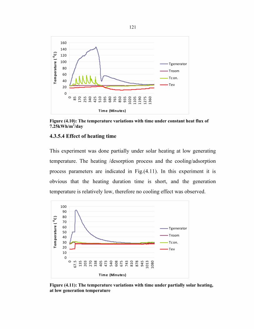
121
0
20
40
60
80
100
120
140
160
0 85 170
255
340
425
510
595
680
765
850
935
1020
1105
1190
1275
1360
T ime (Minutes)
Tem
perature (
OC)
Tgenerator
Troom
Tcon.
Tev
Figure (4.10): The temperature variations with time under constant heat flux of 7.25kWh/m2/day
4.3.5.4 Effect of heating time
This experiment was done partially under solar heating at low generating
temperature. The heating /desorption process and the cooling/adsorption
process parameters are indicated in Fig.(4.11). In this experiment it is
obvious that the heating duration time is short, and the generation
temperature is relatively low, therefore no cooling effect was observed.
0102030405060708090
100
067
.513
520
327
033
840
547
354
060
867
574
381
087
894
510
1310
80
T ime (Minutes)
Tem
perature (
OC)
Tgenerator
Troom
Tcon.
Tev
Figure (4.11): The temperature variations with time under partially solar heating, at low generation temperature
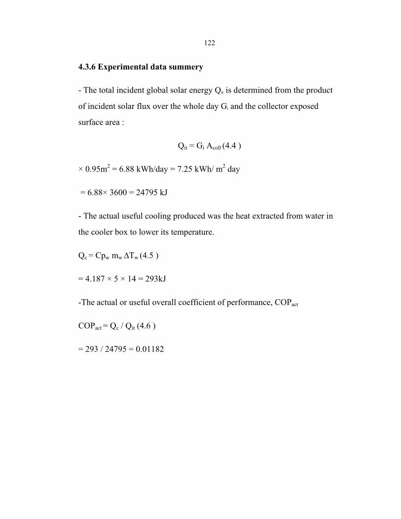
122
4.3.6 Experimental data summery
- The total incident global solar energy Qit is determined from the product
of incident solar flux over the whole day Gi and the collector exposed
surface area :
Qit = Gi Acoll (4.4 )
× 0.95m2 = 6.88 kWh/day = 7.25 kWh/ m2 day
= 6.88× 3600 = 24795 kJ
- The actual useful cooling produced was the heat extracted from water in
the cooler box to lower its temperature.
Qc = Cpw mw ∆Tw (4.5 )
= 4.187 × 5 × 14 = 293kJ
-The actual or useful overall coefficient of performance, COPact
COPact = Qc / Qit (4.6 )
= 293 / 24795 = 0.01182
123
Chapter Five Conclusions and Recommendations
The performance of the adsorption system depends highly on the
adsorption pairs, processes involved, and on the well manufacturing of the
all parts of the system. Generally speaking, enhancing the heat transfer
between metallic plate and adsorbent, increasing the thermal conductivity
of adsorbent are two obvious methods for improving performance of solar
cooler. Simultaneously, choosing a suitable environmental condition may
improve the performance of solar cooler. So long as we choose the
optimization parameters on design of solar system, the practical use of
solar cooler will become more reasonable.
From this study, one can conclude that the possibility of using non-
polluting materials and to save the energy involved in this sector are
obviously the most important characteristics but simplicity, low
maintenance, and the absence of noisy components are also very important
features that make this type of system suitable for numerous other
applications such as air-conditioning in cars or food transportations or solar
cooling. However, the main disadvantage is the long adsorption/desorption
time.
5.1 Conclusions
The following conclusions may be drawn from the foregoing solar powered
solid adsorption cooler studies:-
1- A solar powered solid adsorption cooler using an activated
carbon/methanol adsorbent pair has been successfully designed,
constructed and tested.
124
2-The condenser and evaporator must necessarily be close to each other
and to the collector since the system operates at low pressure, thus they are
located directly under the collector such that the refrigerant flows into them
by gravity.
3- The adsorption bed (generator) is the heart of the system and it has the
greatest effect on the performance of the system. A good design of the
generator leads to smooth operation and better results, so more attention
must be go to the design influence on the performance of the system .
4- The type of the generator such as packed bed or hollow tubes should be
selected according to the manufacturing opportunity.
5- Chilled water was only produced at temperature around 10°C. Fruit,
vegetables and vaccines with preservations temperatures over 13°C can be
preserved .
6-The cooling load of the system is direct proportional to the adsorbed
quantity and to the latent heat of methanol, the higher volume of methanol
adsorbed, the high cooling capacity of the system.
7- The adsorption /desorption tests for activated carbon/methanol pair
showed that there must be sufficient time to get the highest desorption of
methanol, and the optimum time for that was found to be 5-10 hours.
8- The generation temperature must be over 100°C in order to generate
higher volume of methanol from activated carbon.
125
9- It was found experimentally that the activated carbon which was used in
our study has low methanol adsorption capacity and it was about 0.25 kg to
0.29 kg methanol/kg activated carbon, while some researchers [27] indicate
that activated carbon with adsorption capacity of 0.45kg methanol/kg
activated carbon is available commercially.
5.2 Recommendations:
- It is recommended to construct a system with hollow tubes generator,
since it was found that in this type of generator it is easier to control the
leakage and the pressure inside the system.
- A multi generator bed are recommended with the same activated carbon
quantity in order to get higher solar radiation absorption area.
- A high performance vacuum pump can be used with special liquid
Nitrogen cold trap, with such instruments it is easier to decrease the
pressure to the lowest value without losing any methanol vapor.
- A monitoring devices, such as sight glasses, and scaled receivers may be
essential to build in the suitable places in order to indicate the more
correct readings i.e. the volume of the desorption methanol.
- Different types of activated carbon such as activated carbon fiber, or
consolidate activated carbon, which have higher adsorption capacity
may be used to get better results.
- Adopting double glass covers, and using a high quality selective coating
material are two ways to increase properties of solar cooler.
126
References
[1] Wimolsiri Pridasawas, (2006) . Solar-Driven Refrigeration Systems
with Focus on the Ejector Cycle, Doctoral Thesis, Royal Institute of
Technology, KTH, Denmark.
[2] Althous, A., Turnquist, C., and Brancciano, A.(1988). Modern
Refrigeration and Airconditioning, 5th edition, Goodheart-Willcox, INC.,
USA.
[3] Wimolsiri Pridasawas, and Teclemariam Nemariam. (2003), solar cooling, Assignment for Ph.D. Course: Solar Heating, Technical University of Denmark (DTU).
[4] Gengel, Y., and Boles, M., (2006), Thermodynamics an Engineering
Approach, 5th edition,McGraww Hill, NY, USA.
[5] http://www.powerfromthesun.net/index.htm, chapter six. April, (2007).
[6] Rabl, A. (1985). Active Solar Collectors and Their Applications.
USA, Oxford University Press Inc.
[7] Twidell, J. and Weir, T. (1998). Renewable Energy Resources. Great
Britain, E&FN Spon.
[8] http://www.eere.energy.gov/de/thermally- activated/tech-basics.html
Absorption chillers, Technology basics, Energy Efficiency and Renewable
Energy Program, US Department of energy. June, (2007).
[9] Granryd, E. (1998). Introduction to Refrigerating Engineering.
Stockholm, Dept. of Energy Technology, KTH.
127
[10] Foley, Gerald (1993). Photovoltaics in Primary Heath Care,
Working Papers on Solar Energy and Health for the World Solar Summit,
WHO/EPI/LHIS/93.3, Paris.
[11] Zigler F. (1999). Recent developments and future prospects of
sorption heat pump systems. International Journal of Thermals;38:191–
208.
[12] Miller EB. (1929). The Development of SilicaGel, Refrigerating
Engineering, The American Society of Refrigerating Engineers.
[13] A.O. Dieng, R.Z. Wang, (2001) Literature review on solar
adsorption technologies for ice-making and air conditioning purposes
and recent developments in solar technology, Renewable and
Sustainable Energy Reviews 5313–342
[14] Stephan K, Krauss R. (1992).Regulated CFCs and their
alternatives. In: Meunier F, editor. Proceedings: Solid Refrigeration
Symposium. Paris: Ministere de la Recherche et de L’Espace,:32–43.
[15] Suzuki M, (1980).Adsorption for energy transport. In: Adsorption
Engineering. Japan;
[16] M. Pons, J.J. Guilleminot, (1986).Design of an experimental solar-
powered, solid-adsorption ice maker, Transactions of the ASME,
Journal of Solar Energy Engineering 108 (November) 332–337.
[17] F. Lemmini, J. Buret-Bahraoui, (1990)Performance of an adsorptive
solar refrigerator using two types of activated carbon, Energy and
Environment 2 774–779, World Renewable Energy Congress.
128
[18] N.M. Khattab, (2004),A novel solar-powered adsorption
refrigeration module, Applied Thermal Engineering 24, 2747–2760
[19] R.E. Critoph, (1994).An ammonia carbon solar refrigeration for
vaccine cooling, Renewable Energy 5 (Part I) 502–508
[20] F. Meunier, (1994). Sorption solar cooling, Renewable Energy 5
(Part I) 422–429.
[21] Leite, Antonio Pralon Ferreira, Michel Daguenetb. (2000)
Performance of a new solid adsorption ice maker with solar energy
regeneration. Energy Conversion & Management 41 1625-1647
[22] Leite, APF. (1998). Thermodynamic analysis and modeling of an
adsorption-cycle system for refrigeration from low- grade energy
sources. Journal of the Brazilian Society of Mechanical
Sciences;20(3):301-24.
[23] Meunier F, Douss N. (1990).Performance of adsorption heat
pumps: active-carbon-methanol and zeolite-water pairs. In: Trans.
ASHRAE Meeting, Saint Louis, USA.. p. 491-8.
[24] Dubinin MM, Astakhov VA. (1971) Development of the concept of
volume filling of micropores in the adsorption of gases and vapors by
microporous adsorbents. Washington, DC, USA: American Chemical
Society,
[25] E.E. Anyanwu, (2004). Review of solid adsorption solar
refrigeration II :An overview of the principles and theory, Energy
Conversion and Management 45 (2004) 1279–1295
129
[26] R. E. Critoph ,activated carbon adsorption cycles for refrigeration
and heat pumping. Engineering Department, University of Warwick,
Coventry, CV4 7AL. U.K.
[27] L.W. Wang, R.Z. Wang, Z.S.Lu, C.J. Chen, K. Wang , Wang, J.Y
Wu. (2006).The performance of two adsorption ice making test units
using activated carbon and a carbon composite as adsorbent, Carbon
44 2671-2680.
[28] Meunier F, Douss N. Performance of adsorption heat pumps:
activated carbon-methanol and Zeolite-water pairs. In:Trans. ASHRAE
Meeting,Saint Louis, USA. 1990.p.491-8.
[29] Grenier Ph, Pons M. (1984). Experimental and theoretical results
on the use of an activated carbon/methanol intermittent cycle for the
application to a solar powered ice maker. In: Szokolay SV, editor. Solar
World Congress, vol. 1.Pergamon Press;. p. 500–6.
[30] A. Boubakri, (2006).Performance of an adsorptive solar ice maker
operating with a single double function heat exchanger
(evaporator/condenser), Renewable Energy 31 1799–1812.
[31] M. Li, R.Z. Wang. (2002) A study of the effects of collector and
environment parameters on the performance of a solar powered solid
adsorption refrigerator, Renewable Energy, 27 369–382.
[32] Gacciolaa G, Restuccia G. (1994) Progress on adsorption heat
pump, Heat Recovery System & CHP; 14(4):409–20.
130
[33] Pons M.(1987) Experimental date on a solar-powered ice maker
using activated carbon and methanol adsorption pair. Trans ASME, J
Sol Energy Eng 1987;109(4):303–10.
[34] Nadim Samen,(2006) Active Solar Cooling: Processes &
Performance Workshop, Session 1.2 Istanbul, 15+16
[35] Wang RZ. (2001).Adsorption refrigeration research in Shanghai
JiaoTong University. Renewable Sustainable Energy Rev; 5(1):1–37.
[36] Wang RZ. (2001).Performance improvement of adsorption cooling
by heat and mass recovery operation. Int J Refrigeration 2001;24:602–11.
[37] K. Sumathy, K.H. Yeung, Li Yong. (2003). Technology
development in the solar adsorption refrigeration systems, Progress in
Energy and Combustion Science 29 301–327.
[38] Shelton SV, Wepfer WJ. (1990).Solid–vapor heat pump technology.
In: Proceedings of the IEA Heat Pump Conference, Japan: Tokyo;. p. 525–35.
[39] Sun, L. M., Feng, Y. and Pons, M. (1997). "Numerical Investigation
of Adsorptive Heat Pump Systems with Thermal Wave Heat
Regeneration under Uniform-Pressure Conditions." International
Journal of Heat and Mass Transfer 40(2): 281-293.
[40] Ben Amar, N., Sun, L. M. and Meunier, F. (1996). "Numerical
Analysis of Adsorptive Temperature Wave Regenerative Heat Pump."
Applied Thermal Engineering 16(5): 405-418.
131
[41] Wang RZ, Li M, Xu YX, Wu JY. (2000). An energy efficient hybrid
system of solar powered water heater and adsorption ice maker. Solar
Energy 68(2):189–195.
[42] Yeung K.H. and Sumathy K. (2003).Thermodynamic analysis and
optimization of a combined adsorption heating and cooling system
INTERNATIONAL JOURNAL OF ENERGY RESEARCH Int. J. Energy
Res.; 27:1299–1315 (DOI: 10.1002/er.944)
[43] Dai YJ, Sumathy K, Wang RZ, Li YG. (2003). Enhancement of
natural ventelation in a solar house with a solar chimney and a solid
adsorption cooling cavity. Solar Energy.
[44] Zhang, X. J. and Wang, R. Z. (2002). "A New Combined
Adsorption– Ejector Refrigeration and Heating Hybrid System
Powered by Solar Energy." Applied Thermal Engineering 22: 1245-1258.
[45] http://www.powerfromthesun.net/index.htm,chapters(1),June (2007).
[46] Energy Research Centre At An- Najah National University, Solar
measurements, Nablus, Palestine.
[47] http://www.powerfromthesun.net/index.htm, chapters(2), June
(2007).
[48] Dr. Afif Hasan, Dr. Marwan Mahmoud, and Dr. Rateb Shabaneh,
Renewable Energy Assessment for Palestine, Palestinian Energy and
Environment Research Center (PEC) Jerusalem, July 1996.
[49] http://www.powerfromthesun.net/index.htm, chapters(5), June
(2007).
132
[50] M. Li, C.J. Sun, R.Z. Wang, W.D. Cai, (2004). Development of no
valve solar ice maker, Applied Thermal Engineering 24 865– 872
[51] Li M., R.Z. Wang, Y.X. Xu, J.Y. Wu, A.O. Dieng, (2005).
Experimental study on dynamic performance analysis of a flat-plate
solar solid-adsorption refrigeration for ice maker, Applied Thermal
Engineering 25 1614–1622.
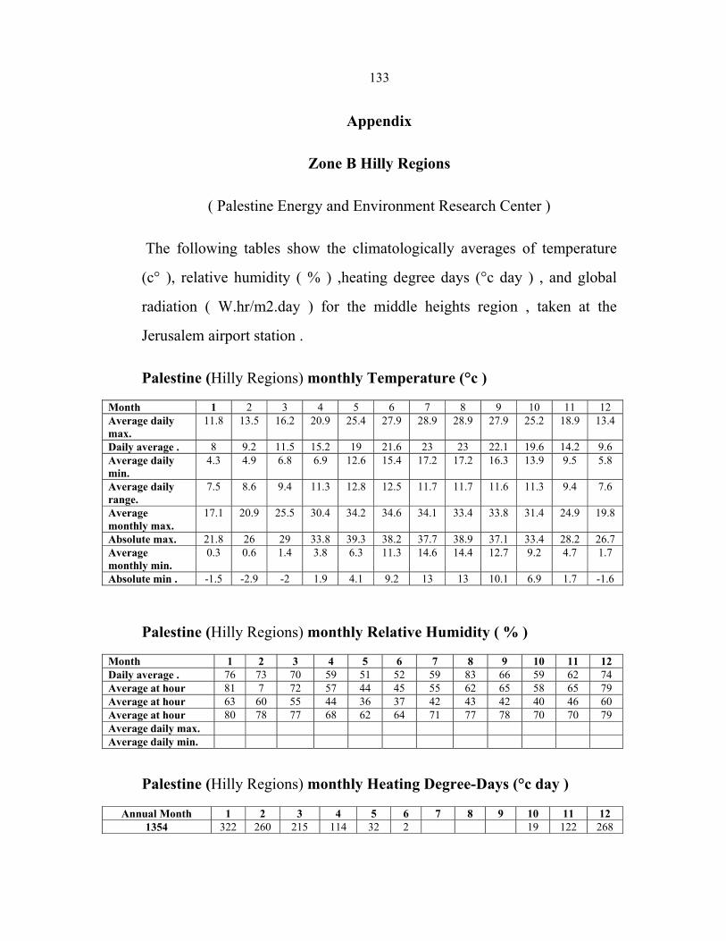
133
Appendix
Zone B Hilly Regions
( Palestine Energy and Environment Research Center )
The following tables show the climatologically averages of temperature
(c° ), relative humidity ( % ) ,heating degree days (°c day ) , and global
radiation ( W.hr/m2.day ) for the middle heights region , taken at the
Jerusalem airport station .
Palestine (Hilly Regions) monthly Temperature (°c )
Month 1 2 3 4 5 6 7 8 9 10 11 12 Average daily max.
11.8 13.5 16.2 20.9 25.4 27.9 28.9 28.9 27.9 25.2 18.9 13.4
Daily average . 8 9.2 11.5 15.2 19 21.6 23 23 22.1 19.6 14.2 9.6 Average daily min.
4.3 4.9 6.8 6.9 12.6 15.4 17.2 17.2 16.3 13.9 9.5 5.8
Average daily range.
7.5 8.6 9.4 11.3 12.8 12.5 11.7 11.7 11.6 11.3 9.4 7.6
Average monthly max.
17.1 20.9 25.5 30.4 34.2 34.6 34.1 33.4 33.8 31.4 24.9 19.8
Absolute max. 21.8 26 29 33.8 39.3 38.2 37.7 38.9 37.1 33.4 28.2 26.7 Average monthly min.
0.3 0.6 1.4 3.8 6.3 11.3 14.6 14.4 12.7 9.2 4.7 1.7
Absolute min . -1.5 -2.9 -2 1.9 4.1 9.2 13 13 10.1 6.9 1.7 -1.6
Palestine (Hilly Regions) monthly Relative Humidity ( % )
Month 1 2 3 4 5 6 7 8 9 10 11 12 Daily average . 76 73 70 59 51 52 59 83 66 59 62 74 Average at hour 81 7 72 57 44 45 55 62 65 58 65 79 Average at hour 63 60 55 44 36 37 42 43 42 40 46 60 Average at hour 80 78 77 68 62 64 71 77 78 70 70 79 Average daily max. Average daily min.
Palestine (Hilly Regions) monthly Heating Degree-Days (°c day )
Annual Month 1 2 3 4 5 6 7 8 9 10 11 12 1354 322 260 215 114 32 2 19 122 268

جامعة النجاح الوطنية
كلية الدراسات العليا
التبريد بواسطة الطاقة الشمسية باستخدام تقنية االدمصاص
إعداد
واثق خليل سعيد حسين
إشراف
عبد الرحيم أبو صفا. د
عماد بريك.د
فـة قدمت هذه األطروحة استكماال لمتطلبات نيل درجة الماجستير فـي هندسـة الطاقـة النظي
.الترشيد بكلية الدراسات العليا في جامعة النجاح الوطنية في نابلس، فلسطين وإستراتيجية2008

ب
التبريد بواسطة الطاقة الشمسية باستخدام تقنية االدمصاص
إعداد
واثق خليل سعيد حسين
إشراف
عبد الرحيم أبو صفا.د
عماد بريك. د
الملخص
لخوف من نفاذه وتلوث البيئة الناتج عن اسـتخدام إن لالرتفاع المتزايد ألسعار الوقود وا
فـي اسـتخراج لمواد الزراعيةل المفرط ستخدامالاوما آلت إليه أسعار الغذاء نتيجة ، هذا الوقود
.مصادر جديدة طبيعية ونظيفة للطاقة إليجادالباحثين ألزم ،الوقود الحيوي
وتعتبر مسـتهلكا رئيسـا الحياة العصرية، التبريد والتكييف ضرورة من ضرورات إن
وعليه فقد تم التركيز في هذا البحث على استغالل الطاقة الشمسية المباشرة في عمليـة للطاقة،
.التبريد والتكييف
الميثانول علـى الكربـون تقنية ادمصاص يعتمد نظام التبريد الشمسي قيد البحث على
تقنية ببساطة التصنيع ومـن مـواد تتميز هذه الإلى تبريد حيث لتحويل الطاقة الشمسية المنشط
ويتميز بعدم وجود أي نوع من الملوثات , ويعمل بدون ضجيج أو أجزاء متحركة, متوفرة محليا
.وال يتطلب أي مصدر للطاقة غير الشمس, للبيئة
تم التطرق في هذا البحث إلى شرح مفصل لعمليات التبريد المختلفة التي تستخدم الطاقة
عا، إضافة إلى دراسة خصائص المواد الماصة ودرجة مواءمتها مع المواد الشمسية ومقارنتها م
لقد تم اختيار عملية التبريد التي تستخدم تقنية ادمصاص الميثـانول علـى الكربـون .الممتصة
.المنشط، ومن اجل ذلك تم بناء وتصميم نظام تبريد يستخدم هذه التقنية ويعمل بالطاقة الشمسية
:الشمسي والذي يعمل بتقنية االدمصاص من األجزاء التاليةيتكون نظام التبريد
المولد أو الممتص أو المجمع الشمسي والذي يقوم بامتصاص الطاقة الشمسية وإيصالها إلى -1
.بداخله ضعتو حيث )المادة الماصة( المنشط الحبيبي الكربون

ج
.إلى سائل المكثف والذي يعمل على تبريد المادة الممتصة وتحويلها من غاز -2
.المبخر والذي يستقبل السائل ومن ثم يكون الفعل ألتبريدي -3
.حيث يوضع المبخر بداخله, لتيس سوالذي يصنع من مادة ستانل, صندوق الماء البارد -4
.يوضع بداخله صندوق الماء البارد والمبخر, الصندوق المعزول حراريا -5
حيث يعتبر قلب هذا النظام ، ) المولد( ي إن أهم جزء في هذا النظام هو المجمع الشمس
وقد تم اختيار النوع المستوي بمسـاحة .وتقاس فاعلية النظام ومردوده بحسن تصنيع هذا القلب
0.95m2 يتكون األول من أنبوب حلزوني مغمور في , المكثفات لقد تم اختبار نوعين من .تقريبا
بينما اآلخر يتكون من أنبوب ذي ريش ينحـدر بشـكل انسـيابي لتسـهيل جريـان , وعاء ماء
.الميثانول
-:كما يلي لقد قمنا بإجراء عدة تجارب واختبارات لتقييم أداء هذا النظام وهي
متصاص الميثانول وعلـى موائمـة كميـة على ا الحبيبي المنشط قدرة الكربون تم اختبار – 1
.الحبيبي المنشط الميثانول مع كمية الكربون
تأثير درجة حرارة المولد أو درجة حرارة الكربون المنشط وتأثير شدة اإلشـعاع الشمسـي -2
وجد إن درجة حرارة الكربون المنشط في المولد يجب أن تزيد عـن .على أداء النظام الشمسي
ي تحصل عملية المج، وكلما زادت درجة الحـرارة زادت عمليـة تبخـر درجة مئوية لك 100
.الميثانول وبالتالي يزداد الفعل التبريدي
الضغط العامل عنصر مهم جدا من اجل تحقيق عمليـة أنتحديد الضغط العامل حيث وجد -3
kPa 20 اقل من إلىبضغط تخلخلي كبير يصل إالالنظام ال يعمل هذا أنالتبريد حيث وجد
يكون انسيابي وقليل المقاومة لجريان أنالمكثف يجب أنم اختيار نوع المكثف حيث وجد ت -4
ذي انبـون تم تصنيع مكثف يتكون مـن وبالتاليبين المولد والمبخر مكنأالميثانول وقريب ما
.لتجنب حصول هبوط ضغط عالي ريش ينساب ما بين المولد والمبخر وذلك

د
10حـوالي ختبارات استطعنا الحصول على ماء في المبخر بدرجـة حـرارة في معظم اال -5
الشمسـي المطبـق اإلشعاعبشكل مباشر بشدة تتأثردرجة الحرارة هذه أندرجات مئوية حيث
ال أنلعملية التسـخين يجـب األفضلالفترة الزمنية أنتزاز والمج حيث وجد مفترة اال وبطول
10الزمنية الالزمة للحصول على التبريد تمتد إلى أكثـر مـن بينما الفترة ساعات 5تقل عن
الحرارة التي حصلنا عليها تتناسب مع استخدام هـذا النظـام فـي عمليـات درجة إن .ساعات
.وخاصة في المناطق النائية ،الشرب وماء واللقاحات واألدوية األطعمة حفظالتكييف و
حجم المبخر إنوجد كي نظام التبريد المصنع وقديحا رختبنظام تبريد شمسي في الم تم بناء -6
ال يزيد عن اكبر كمية من إنيجب المبخر إن حجمهذا النظام حيث وجد أداء على تأثير مهمله
المنشـط المسـتخدم لكربـون لسعة االدمصاص إنالميثانول يمكن شحنها في هذا النظام ووجد
.كغم كربون منشط/ كغم ميثانول 0.26تساوي
انـه إال يتمتع بقدرة عالية على امتصاص الحرارة الدراسة المولد المستخدم في هذه أنوجد -7
جاسئ يتكـون آخرتم اقتراح تصميم وبالتاليالضغط العامل يعاني من مشكلة عدم الحفاظ على
فيـه متحـدة تكون بشكل ينأنبوبحيث يتوضع كل داخلي و خارجي نابيبمجموعة من األ من
فيه و يتوضع الكربون المنشط الداخلي مثقب من اجل جريان الميثانول األنبوبكون المحاور وي
.بينهما


![Contribution to the Modeling of a Solar Adsorption Refrigerator … · Solar adsorption refrigeration machines have been the subject of numerous studies [2] [3] [4]. These machines](https://img.pdfslide.net/doc/110x75/6021199f4a1eb77a9549a3fc/contribution-to-the-modeling-of-a-solar-adsorption-refrigerator-solar-adsorption.jpg)


![Development Trend of Solar-powered Adsorption ...Reference [14] developed a model of a solar adsorption refrigeration unit powered through a 3.7 2𝑚 parabolic trough solar collector](https://img.pdfslide.net/doc/110x75/5f4299d9af7a2936e42c6bcf/development-trend-of-solar-powered-adsorption-reference-14-developed-a-model.jpg)