Embed Size (px)
Citation preview

Solar Sails
–
Problems and Progress
Ulrich R.M.E. Geppert
Institute for
Space
Systems, Bremen, GermanyFebruary
15th 2008

Why Solar Sail Propulsion?•
large s/c velocity
achievable
km/s160 1yr after mm/s5~AU)1(with ,km/s11 22 ssss vav
●
non-Keplerian
orbits
possible
–
even
exotic
ones
Missions into
the
deep
space
accomplishable only
with
solar sails!
By
an appropriate
sequence
of sail orientations, any
point in the
solar system
–
and beyond
–
can
be
reached!
●
essentially
open
launch
window

Acceleration
Small
BUT
Long-Lasting
]s mm[]gm[
12.92
)AU1,0( 2-2-2
s0rad
cr
La
η ≤ 0.9: efficiency, σ
< 10 g m-2
→ arad
~ 1 mm s-2
BUT
we
have
plenty
of time:
arad
•
1000 days
→
(100 < vsail
< 1000) km s-1

Basic Advantage: Much
Larger Isp
rocketsfor s450ln
1exp
2
1sp
sp12
mmg
vIIg
vmm
Isp
= change
of momentum
per unit
propellant
for
solar sail
Isp
= ∞ → effective
specific
impulse
measured
by
settingm1 = mass(sail
+ payload), m2 = mass(payload);
with
Δv = arad
•
T and mass(payload) = mass(0.5 sail
mass) forT = 1000 days
and arad
= 1mm s-2:
propulsion sailsolar for 80003ln
1rad sg
TaI sp
Ziolkowski
1897:

Non-Keplerian Orbits•
continuously
available
radiation pressure:
all solar sail
orbits are
non-Keplerian
•
some
orbits
so strongly
perturbed
→ new
family
ifarad
~ agrav
(locally)

Non-Keplerian Displaced Orbits
-
mission
circles
the
inertial
Z-axisof the
sun,
-
observes
coronal
mass
ejections
onall
sides
of sun,
-
constant
communication
with
Earth,-
synchronization
with
Earth‘s
rotation
about
sun
possible,
- patched
displaced
orbits- examine
much
more,
environment
around
the
sun,

Maneuver
into
the
Space

Maneuver
towards
the
Sun

arad
~ Sail Lightness β
12
s
cGML
σ: sail
loading, i.e. mass
per sail
area
σ*
: critical sail loading, follows from agrav
= arad

Equation of Motion
lightness sail:,coscos2
22
22
srad
nr
GMnr
La
rer
GMmtrM
221
2
dd
nr er
GMmer
GMmtrm
2222
22
cosdd
+
0cos)(d
d 222
2
nermM
GMmtR
→ not
suitable
inertial
frame
of reference
→ better
to use
an inertial
system
with
R=0 in C

Equation
of Motion , Frame in C
GMmMGer
ert
r
tr
Mm
tr
rrrrmrMR
nr
)( where,cosdd
dd1
dd
:followswith;0 :i.e.,0:Cin
2222
2
22
2
2
21221
This
vector
equation
of motion
may
now
be
transformed
intoscalar
components
in any
convenient
frame
of reference.

Sail
Coordinatesunit
vectors:
r: sun
linep: normal to the
orbital plane
p
x r: transverse
to p
and r
cone
angle α: between
sun
lineand sail
normal
clock
angle δ: between
projectionof sail
normal and some
reference
direction
onto
a plane normal tothe
sun
line
resolving
n
along
the
radial, orbit
normal, and transverse
directions:
n
= cosαr
+ sinαcosδp
+ sinαsinδ(p
x r)
test: α=δ=0o
→ n~r, α=90o, δ=0o
→ n~p, α=δ=90o
→ n~(p
x r)

Equation
of Motion in Spherical
Coordinates
cossincoscossindd
dd
dd1
sinsincossindd
dd2
dd
ddcos1
coscosdd
dd
dd
22
22
22
2
322
222
2
2
rtr
tr
tr
rttr
tr
tr
rrtr
tr
tr
We
find the
position
of the
sail
r(r,θ,φ,t)
asa function
of ist cone
and clock
angle, α
and δ, and as function
of the
solar luminosity
Ls
and the
sail
loading
σ
(β~Ls
/σ)

Main Problems
•
Deployment
of the
Sail
•
Sail
Loading
< 1.53 gm-2
•
Degradation of the
Sail
by
Solar Wind and Electromagnetic
Radiation
Each
of this
Problems Demands
the
Work Capacity
of a Department and/or
Collaboration
with
Hightech Industry

Deployment of the Sail•
up to now
no successful
attempt!
•
most
recent
entry
at the
DLR solar sail
hompage: Dec. 1999:1997 DLR-NASA/JPL solar sail
mission
pre-phase-A
study
•
in the
90th: -
Znamya
deployment
test 1993, 20m,
~ successful, illumination
of northern
Russia-
inflatable
antenna
deployment, NASA
1996, 14m, not
successful

Sail
Design Square Sail
requires
booms
to support
the
sail
material
NASA/JPL
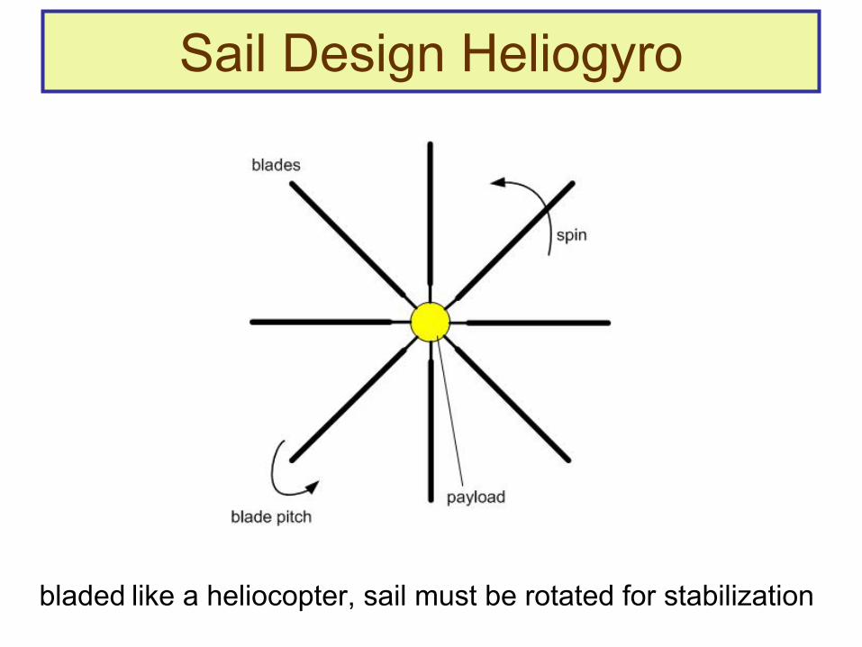
Sail Design Heliogyro
bladed
like
a heliocopter, sail
must
be
rotated
for
stabilization

Sail
Design Disc Sail
circular
sail, controlled
by
moving
the
center
of mass
relative to the
center
of light pressure
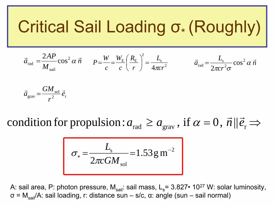
Critical Sail Loading σ* (Roughly)
nM
APa 2
sailrad cos2
2
s2
EE
4 crL
rR
cW
cWP
n
crLa
2
2s
rad cos2
r2sol
grav er
GMa
rgravrad ||,0if, :propulsionfor condition enaa
2
sol
s mg53.12
cGML
A: sail
area, P: photon
pressure, Msail
: sail
mass, Ls
= 3.827•
1027
W:
solar luminosity,σ
= Msail
/A: sail
loading, r: distance sun
–
s/c, α: angle (sun
–
sail
normal)
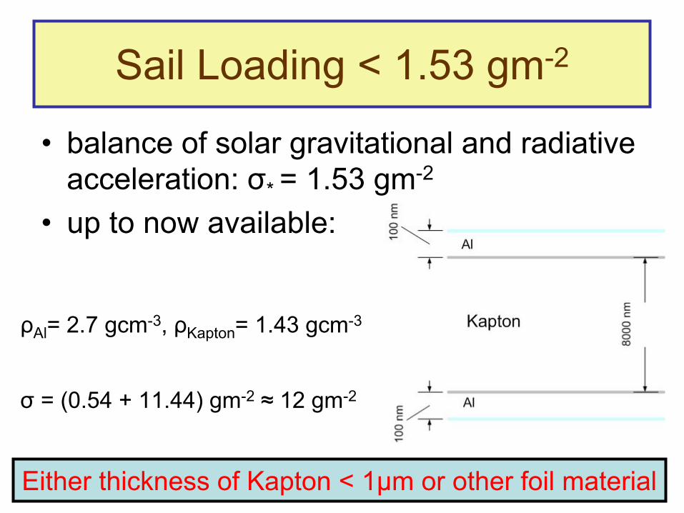
Sail Loading < 1.53 gm-2
•
balance
of solar gravitational
and radiative acceleration: σ* = 1.53 gm-2
•
up to now available:
ρAl
= 2.7 gcm-3, ρKapton
= 1.43 gcm-3
σ
= (0.54 + 11.44) gm-2
≈
12 gm-2
Either
thickness
of Kapton
< 1µm or other foil material

Degradation
Sail MaterialSuffers From
Solar Electromagnetic
RadiationSolar Wind Residual Atmosphere
Cosmic Radiation

Complex
Irradiation
Facility (KOBE)

Solar Electromagnetic
Radiation
•
Averaged
solar irradiance
≈
1370 Wm-2
•
47% visible
light, 380…780nm ~ 1.6…3.3eV→ thrust
•
46% infrared
radiation, ≥
780nm ~ ≤
1.6eV→ heat
•
7% UV, X, Γ, 6·10-6…380nm ~4eV…200MeV→ ionization

Solar Wind Constituents•
protons
2keV…200MeV
•
electrons
1eV…2MeV•
low
energy
particles:
electron
1…2eVprotons
2…4keV
→ ionizing
Al•
higher
energetical
particels:
→ destroying
Kapton
structures

Proton & Electron
Fluxes
(400000-1000km)

Scaling
of Proton/Electron
Currents
lab
real-18
KOBEscale e/p102415.6 t
tAj
jreal
[A]: p+/e-
current
necessary
to simulate
a solar sail
flight
of treal
[cm-2
s-1]: p+/e-
flux
expected
(by
OMERE) for
a given
sail
trajectory,
AKOBE
[cm2]: irradiated
area
in the
KOBE experiment,
treal
[s]: real solar sail
flight
time, tlab
[s]: time available
in the
lab to simulate
the
flight,
e.g. at 300keV: Φ=107p+cm-2s-1
= 1.6pAcm-2,
if
we
intend
to simulate
a 20 years
flight
during
1 week→ we
have
in KOBE to apply
a jscale
= 1.67μA

Energy Loss
= Density
×
Total Stopping Power
Proton Energy Loss
within
the
Kapton

Heat
Release by
High-energetic
p+/e-
energy
balance: Qin
= Qout
Qin
= dE/dx(per
p+/e-) ·
foil thickness ·
p+/e—current
Qout
= σSB
·
εAl
· A · (Ts4
– Tenv
4) 4/1
4env
AlSB
in
T
AQTs
For 1MeV proton
and a current
of 1μA with
εAl
and A = 200 cm2
we
shouldobtain
Ts
≈
335 K. A doubling
of the
proton
current
would
endanger
thestability
of Kapton.

Protonirradiation
of „Our“
Foils
at Notre Dame, U.S.A.

Van de Graaff
Accelerator 30 MeV

Proton Beam Line

Irradiation
of Al-Covered
Kapton
Foils with
Protons of 300 and 600 keV
•
600 keV: all protons
are
transmitted•
300 keV: all protons
are
stopped
within
the
foil•
effects
of
-
beam
thickness-
wobbling
-
intensity
all probes
are
irradiated
with
the
same
dose of 2 mC

600 keV 300 keV
SRIM Simulation of Proton Stopping

600
keV, A2 , beam
~ 1mm, wobbling
~ 1Hz

300 keV,
A2
Beam
Defocused, No Wobbling
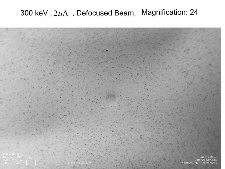
300 keV
, A2 , Defocused
Beam, Magnification: 24

300 keV
, A2 , Defocused
Beam,Magnification: 6290

G = 3, i.e. 3 H2
molecules
/ 100 eV, i.e. for
one
600 keV
proton
18000 H2
molecules,
if
abstracted
→ they
cleave
H + H → H2
for
1µA of 600 keV
protons: ~ 3×10¹⁶
H2
molecules per second,
H2
molecules
try
to escape
through
the
weakest
sites
of the
foil.
Kapton
structure
will be
destroyed!

Fringe
Area
Irradiated/Blank
foil, 300 keV, Defocused
Beam
+ Wobbling

Spectrum
of Region 2 (Blank Foil): Al Dominates

Spectrum
of Region 4 (Irr. Foil): Kapton
Constituents
Dominates

Conclusions
of ND-Experiments
•
best choice
for
uniform irradiation: defocused
beam
& wobbling
•
alternative: wobbling
at high frequencies•
stopping
power in Kapton: no energies
larger than
~ 500 keV
necessary•
avoid
burn
through: intensities
< 200 nA/cm2
•
optical
properties
determined
by
C, O, and Al chunks
of ~ few
100 nm sputtered
on the
surface

Final Remarks•
we
have
got
some
experience
to work
with
KOBE
•
sail
foil
quality
suffers
from-
reduced
reflectivity
-
destruction
of the
Kapton
substrate(heat
release
and H + H → H2
)
•
we
recommend
to deploy
any
sail
only above
the
outer
radiation
belt
(18000km)

But First of All:
WE NEED A PROJECT WHICH DEMONSTRATESFOR THE FIRST TIME THE FEASIBILITY OF SOLAR SAIL TECHNOLOGY!

We should very actively campaign for the
extremely promising solar sail technology!

1st Cosmic VelocityVelocity which
a body
must
have
to move
on a circular
orbit
around
the
earth.
Condition: centripetal
force = gravitational
force
km/s 7.91km/h28400:Earth
Earth1Earth
2Earth1
rGMvrrfor
rmMG
rmv

2nd Cosmic VelocityTo remove
a body
from
the
Earth‘s
gravitational
attraction
it
has to get
so
much
kinetic
energy
Ekin,2
, that
this
energy
is
≥
difference
betweenfinal and initial
energy.
In the
limit
(=): Ekin,2
= final energy
–initial
energy
km/s 11,2km/h4030022
210
1Earth
Earth2
Earth
Earth22
Earthkin,2
vr
GMv
rmMGvm
rmMGE

Maximum Gravitational
Caused
Velocity
The
largest
velocity
aquired
by
gravitational
acceleration
in our
solar system
is
the
free-fall
velocity
of a body
at the
solar surface.
km/s6202
sun
sunff
RGMv


![Andy Sails[1]](https://img.pdfslide.net/doc/110x75/577d275c1a28ab4e1ea3bb31/andy-sails1.jpg)


![Solar Sails[1]](https://img.pdfslide.net/doc/110x75/577d22ae1a28ab4e1e97fcd0/solar-sails1.jpg)