Embed Size (px)
Citation preview
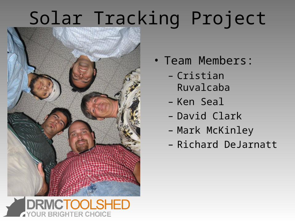
Solar Tracking Project
• Team Members:– Cristian Ruvalcaba– Ken Seal– David Clark– Mark McKinley– Richard DeJarnatt

Mark McKinley
• Project Lead
• Time Management
• Budget Analyst

Richard DeJarnatt
• Parts Manager
• Lead Photographer
Cristian Ruvalcaba
• Web Designer
• Asst. Photographer
David Clark
• Report Editor

Ken Seal
• Presentation Design
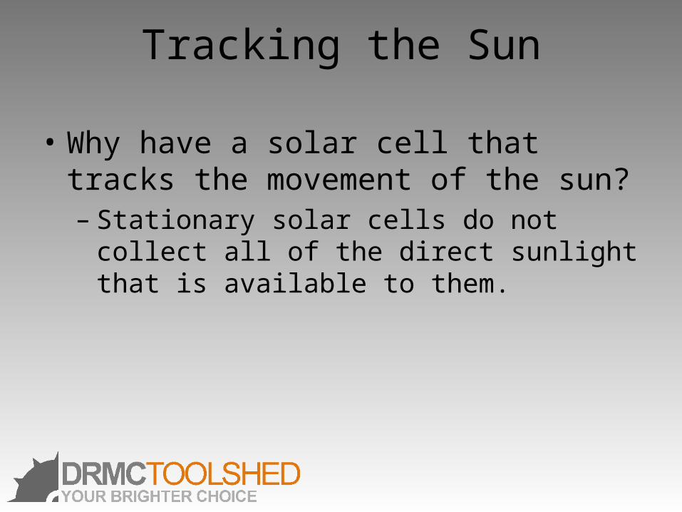
Tracking the Sun
• Why have a solar cell that tracks the movement of the sun?– Stationary solar cells do not collect all of the
direct sunlight that is available to them.
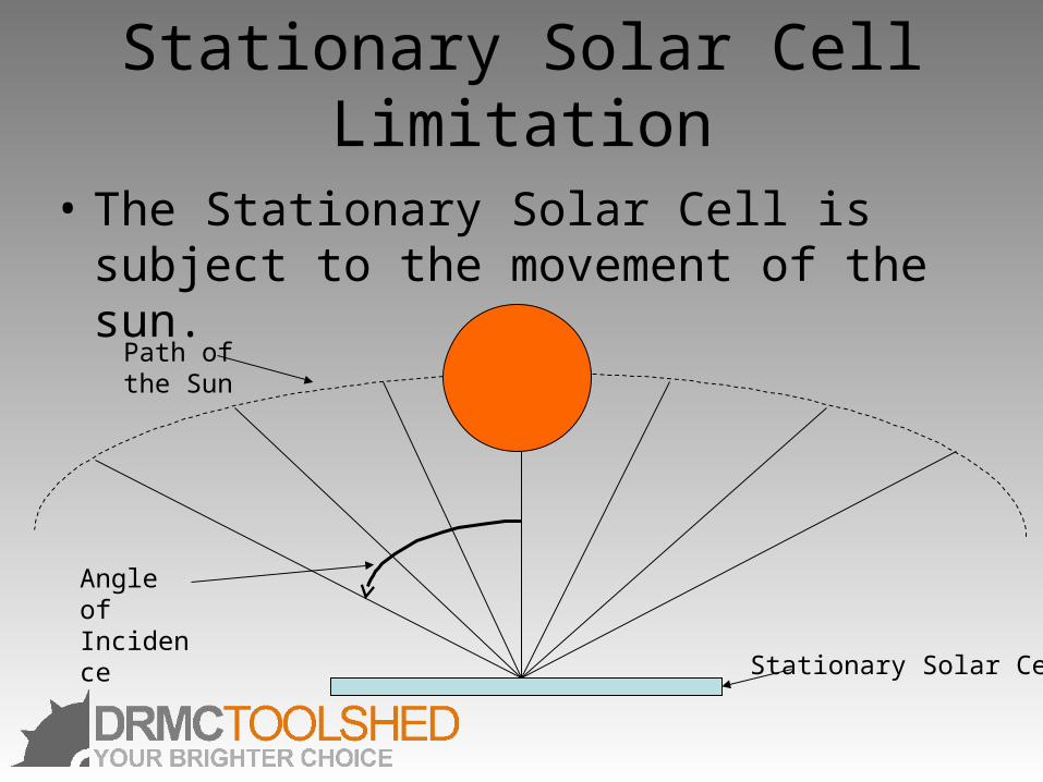
Stationary Solar Cell Limitation
• The Stationary Solar Cell is subject to the movement of the sun.
Stationary Solar Cell
Angle ofIncidence
Path of the Sun
Stationary Solar Cell• By taking the cosine of the angle of incidence over 180 (the path of
the sun in the sky) we find that the solar cell is not gathering 100% of the direct sunlight throughout the day.
• The efficiency can be found by adding the area under the curve.
Stationary Solar Cell
• The stationary solar cell is most effective at gathering sunlight when the angle of incidence is zero or within a few degrees.
• This occurs only for a short period every day when the sun is directly over the solar cell.
• The solution for this problem is to move the solar cell to meet the sun and lessen the angle of incidence to near zero throughout the day.
Tracking Solar Cell
• The ability to move the solar cell to receive the most direct sunlight would allow for the light gathering efficiency of the cell to be at a maximum level.
• The angle of incidence would be kept near 0 for the entire duration that the sun was visible to cell.
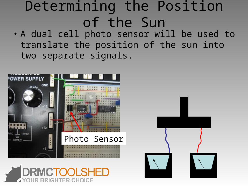
Determining the Position of the Sun• A dual cell photo sensor will be used to translate
the position of the sun into two separate signals.
Photo Sensor
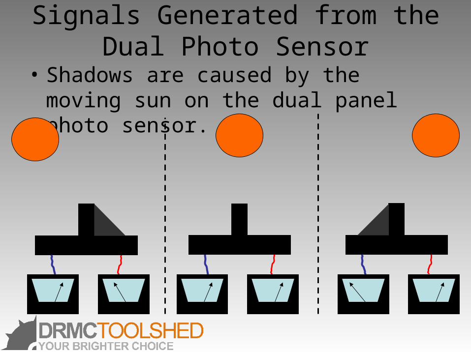
Signals Generated from the Dual Photo Sensor
• Shadows are caused by the moving sun on the dual panel photo sensor.
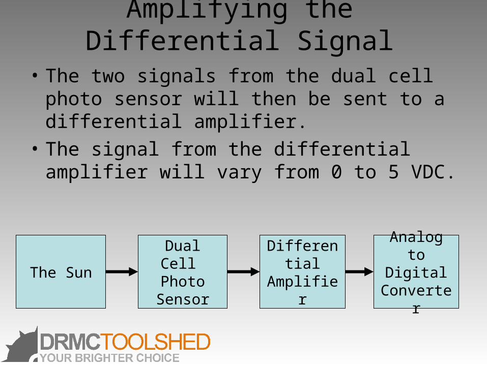
Amplifying the Differential Signal
• The two signals from the dual cell photo sensor will then be sent to a differential amplifier.
• The signal from the differential amplifier will vary from 0 to 5 VDC.
Dual Cell Photo
Sensor
Differential Amplifier
Analog to Digital
ConverterThe Sun
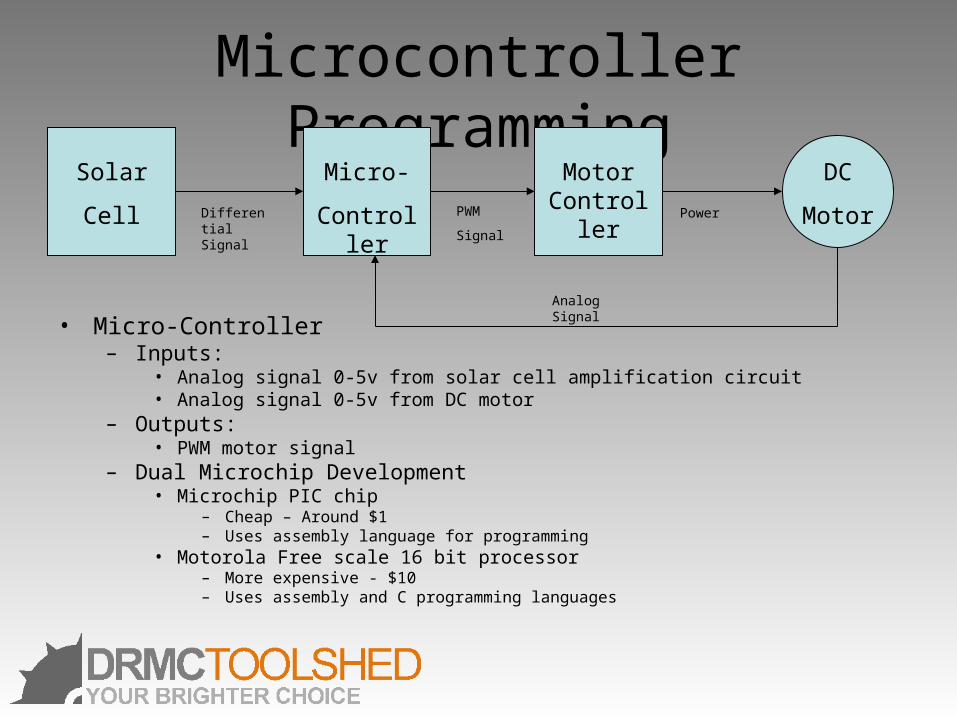
Microcontroller Programming
• Micro-Controller– Inputs:
• Analog signal 0-5v from solar cell amplification circuit• Analog signal 0-5v from DC motor
– Outputs:• PWM motor signal
– Dual Microchip Development• Microchip PIC chip
– Cheap – Around $1– Uses assembly language for programming
• Motorola Free scale 16 bit processor – More expensive - $10– Uses assembly and C programming languages
Solar
Cell Differential Signal
Micro-
Controller
Motor Controller
DC
MotorPWM
Signal
Power
Analog Signal
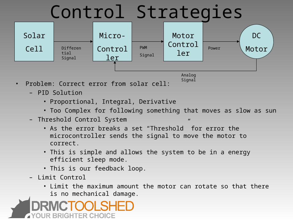
Control Strategies
• Problem: Correct error from solar cell:– PID Solution
• Proportional, Integral, Derivative• Too Complex for following something that moves as slow as sun
– Threshold Control System• As the error breaks a set “Threshold” for error the microcontroller sends the
signal to move the motor to correct. • This is simple and allows the system to be in a energy efficient sleep mode. • This is our feedback loop.
– Limit Control• Limit the maximum amount the motor can rotate so that there is no
mechanical damage.
Solar
Cell Differential Signal
Micro-
Controller
Motor Controller
DC
MotorPWM
Signal
Power
Analog Signal
PWM to H Bridge
• Receives a Pulse Width Modulated signal from microcontroller
• Transforms duty cycle to voltage– High duty cycle – positive voltage
• Motor runs forward
– Low duty cycle – negative voltage• Motor runs backwards
H Bridge
• Receives Voltages and Control Signals
• Control Signals energize motor to turn in appropriate direction
• And at correct speed
Overview
• Why use the tracker?
• The heart of the design
• The brain of the design
• The limbs of the design

Questions…