Embed Size (px)
Citation preview

Instruction Manual
Solar TurbineAddendum
Version 6.0
D2-3406

©1999 Rockwell International Corporation
The information in this manual is subject to change without notice.
Throughout this manual, the following notes are used to alert you to safety considerations:
Important: Identifies information that is critical for successful application and understanding of the product.
!ATTENTION: Identifies information about practices or circumstances that can lead to personal injury or death, property damage, or economic loss.
Reliance is a trademark of Rockwell Automation.
!ATTENTION: Only qualified electrical personnel familiar with the construction and operation of this equipment and the hazards involved should install, adjust, operate, or service this equipment. Read and understand this manual and other applicable manuals in their entirety before proceeding. Failure to observe this precaution could result in severe bodily injury or loss of life.
ATTENTION: The user must provide an external, hardwired emergency stop circuit outside of the drive circuitry. This circuit must disable the system in case of improper operation. Uncontrolled machine operation may result if this procedure is not followed. Failure to observe this precaution could result in bodily injury.
ATTENTION: The user is responsible for conforming with all applicable local, national, and international codes. Failure to observe this precaution could result in damage to, or destruction of, the equipment.

Contents I
CONTENTS
Chapter 1 Introduction1.1 Intended Audience........................................................................................... 1-11.2 Other Required Manuals ................................................................................. 1-1
Chapter 2 About the Drive and Cabinet2.1 Identifying the Solar Turbine Drive by Model Number and Ratings................. 2-12.2 Enclosure Rating ............................................................................................. 2-22.3 Identifying Solar Turbine Cabinet Components ............................................... 2-2
Chapter 3 Cabinet Mounting and Wire Routing3.1 Mounting the Drive .......................................................................................... 3-1
3.1.1 Verifying the Drive’s Watts Loss Rating ................................................ 3-23.2 Cabinet Wire Routing ...................................................................................... 3-33.3 Grounding the Cabinet .................................................................................... 3-6
Chapter 4 Installing Power Wiring4.1 Installing Fuses for Branch Circuit Protection.................................................. 4-14.2 Installing a Required External/Separate Input Disconnect .............................. 4-14.3 Installing Power Wiring from the DC Power Supply to the Drive’s Internal
DC Bus Terminals ........................................................................................... 4-34.4 Recommended Motor Lead Lengths ............................................................... 4-5
Chapter 5 Troubleshooting the Drive5.1 Verifying that DC Bus Capacitors are Discharged........................................... 5-15.2 Replacement Parts .......................................................................................... 5-1
Appendix A Solar Turbine Drive Parameters ...............................................................................A-1

II Solar Turbine Addendum
Contents III
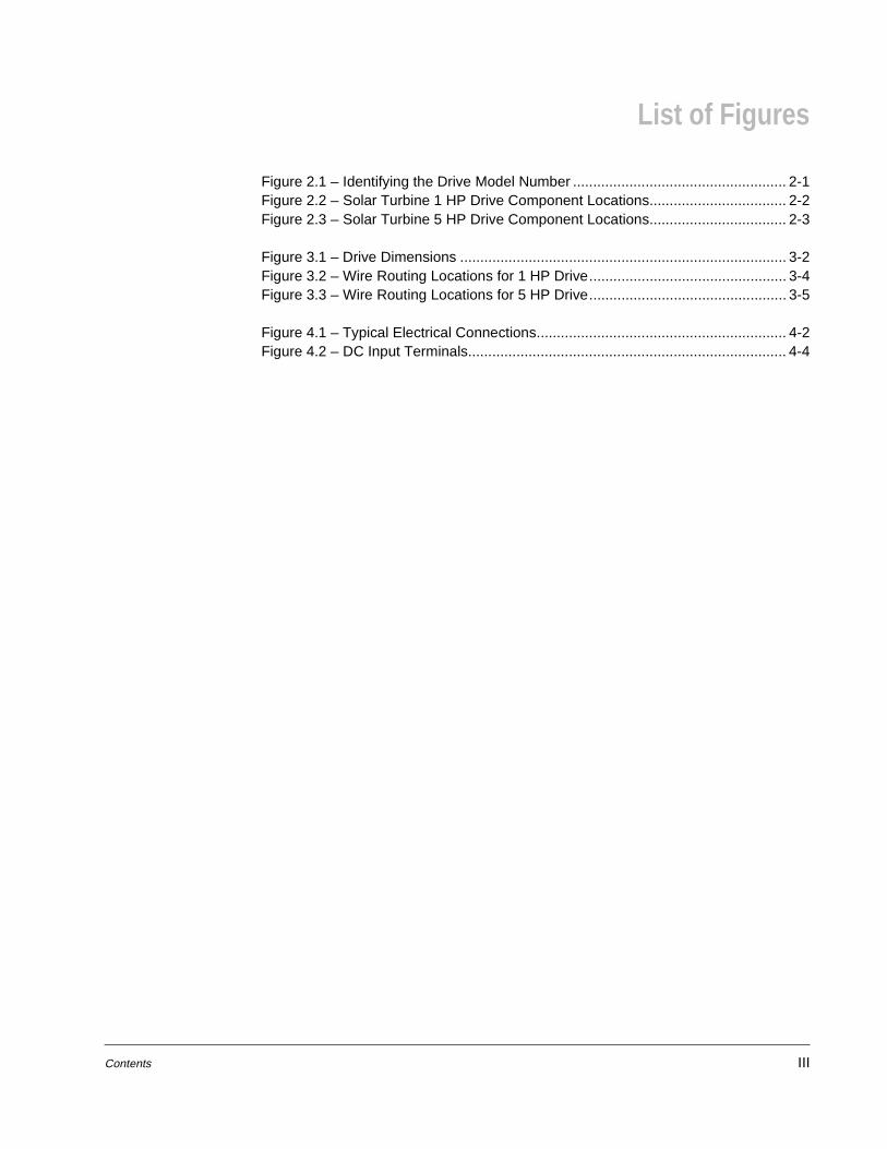
List of Figures
Figure 2.1 – Identifying the Drive Model Number ..................................................... 2-1Figure 2.2 – Solar Turbine 1 HP Drive Component Locations.................................. 2-2Figure 2.3 – Solar Turbine 5 HP Drive Component Locations.................................. 2-3
Figure 3.1 – Drive Dimensions ................................................................................. 3-2Figure 3.2 – Wire Routing Locations for 1 HP Drive................................................. 3-4Figure 3.3 – Wire Routing Locations for 5 HP Drive................................................. 3-5
Figure 4.1 – Typical Electrical Connections.............................................................. 4-2Figure 4.2 – DC Input Terminals............................................................................... 4-4

IV Solar Turbine Addendum

Contents V
List of Tables
Table 2.1 – Drive Ratings ......................................................................................... 2-1
Table 3.1 – Drive Dimensions and Weights.............................................................. 3-1Table 3.2 – Power and NEMA Enclosure Ratings .................................................... 3-2
Table 4.1 – Recommended Input Line Fuse Ratings ............................................... 4-1Table 4.2 – Recommended Power Wire Sizes ......................................................... 4-3Table 4.3 – Terminal Tightening Torques................................................................. 4-4Table 4.4 – Recommended Motor Lead Lengths ..................................................... 4-5
Table 5.1 – Solar Turbine Drive Replacement Parts ................................................ 5-2

VI Solar Turbine Addendum

Introduction 1-1
CHAPTER 1Introduction
This addendum covers the features and specifications that are unique to the GV3000/SE Solar Turbine drives. GV3000/SE Solar Turbine drives operate from a 120 VDC input, requiring a different power supply than standard GV3000/SE drives. Only product information that is unique to Solar Turbine drives is covered in this addendum. This addendum must be used along with the GV3000/SE software and hardware instruction manuals listed in section 1.2.
1.1 Intended Audience
This addendum is intended for the following qualified personnel:
• Rockwell Automation Global Technical Service personnel who are familiar with the features described.
• Product end users
1.2 Other Required Manuals
This addendum must be used with the following publications:
• D2-3359 GV3000/SE AC General Purpose (Volts/Hertz) and Vector Duty DriveSoftware Start-Up and Reference Manual
• D2-3360 GV3000/SE AC Power Modules Hardware Reference, Installation, and Troubleshooting

1-2 Solar Turbine Addendum
About the Drive and Cabinet 2-1
CHAPTER 2About the Drive and Cabinet
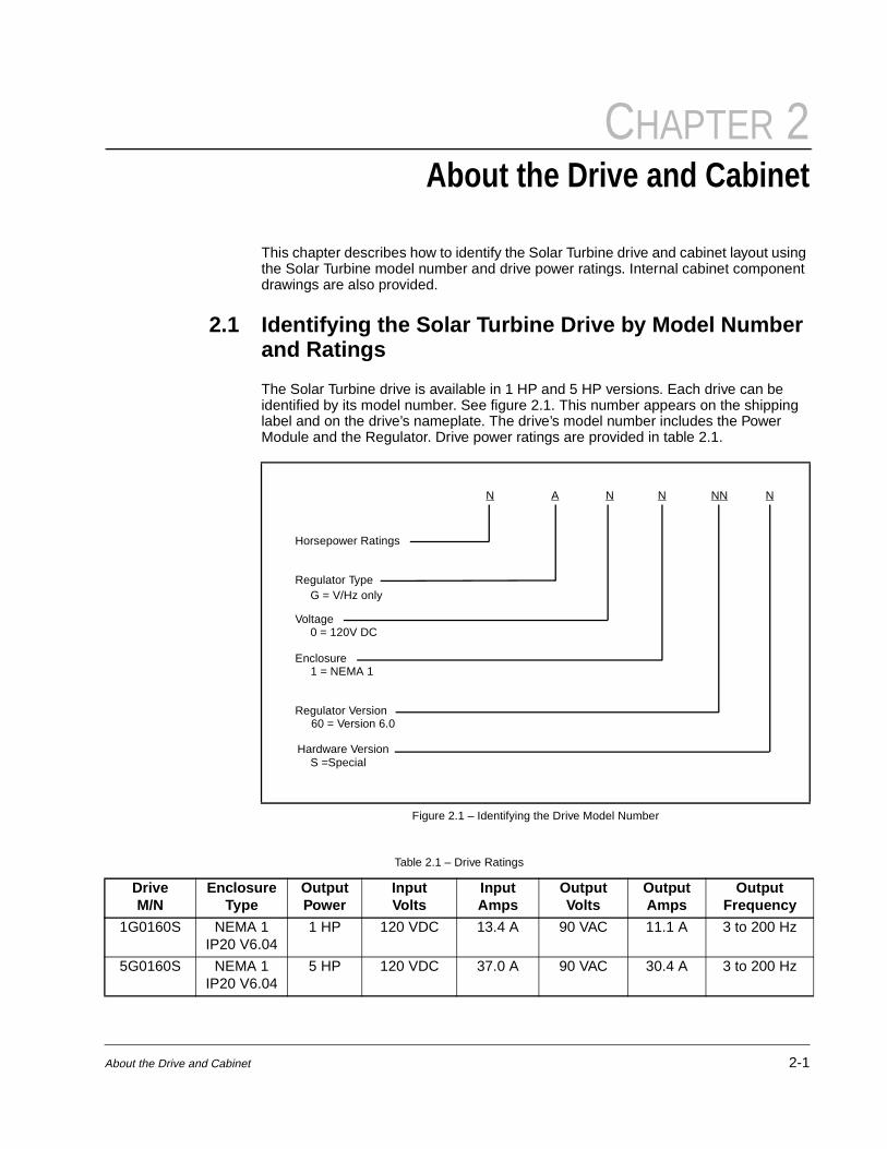
This chapter describes how to identify the Solar Turbine drive and cabinet layout using the Solar Turbine model number and drive power ratings. Internal cabinet component drawings are also provided.
2.1 Identifying the Solar Turbine Drive by Model Number and Ratings
The Solar Turbine drive is available in 1 HP and 5 HP versions. Each drive can be identified by its model number. See figure 2.1. This number appears on the shipping label and on the drive’s nameplate. The drive’s model number includes the Power Module and the Regulator. Drive power ratings are provided in table 2.1.
Figure 2.1 – Identifying the Drive Model Number
Horsepower Ratings
Regulator Type
Voltage
Enclosure1 = NEMA 1
Regulator Version 60 = Version 6.0
Hardware VersionS =Special
0 = 120V DC
N NA N NN N
G = V/Hz only
Table 2.1 – Drive Ratings
DriveM/N
Enclosure Type
Output Power
InputVolts
Input Amps
Output Volts
Output Amps
Output Frequency
1G0160S NEMA 1 IP20 V6.04
1 HP 120 VDC 13.4 A 90 VAC 11.1 A 3 to 200 Hz
5G0160S NEMA 1IP20 V6.04
5 HP 120 VDC 37.0 A 90 VAC 30.4 A 3 to 200 Hz

2-2 Solar Turbine Addendum
2.2 Enclosure Rating
The Solar Turbine 1 HP and 5 HP cabinets have a NEMA 1 enclosure rating:
NEMA 1: Vented. Contains a communication access door that allows access to the communication port without removing the cover. Intended for general-purpose indoor applications.
2.3 Identifying Solar Turbine Cabinet Components The Solar Turbine drive has the following main components. The identification numbers provided correspond to the numbers used in figure 2.2 (1 HP) and figure 2.3 (5 HP).
1. Capacitor Board/Input Capacitors 6. Current Feedback Board
2. Fan Assembly 7. Regulator Board
3. Internal Fan Assembly 8. IGBT Module
4. Power Board 9. Signal Board
5. Membrane Switch (Keypad/Bracket) 10. Gate Driver Board
Figure 2.2 – Solar Turbine 1 HP Drive Component Locations
FAN ASSEMBLY(INTERNAL)
FAN ASSEMBLY
1 2 3
4
MEMBRANE SWITCH(KEYPAD/BRACKET)
5
REGULATORBOARD
CURRENT FEEDBACK BOARD
6
7
MN1G0160S

About the Drive and Cabinet 2-3
Figure 2.3 – Solar Turbine 5 HP Drive Component Locations
2 3
8
1
4
9
10
5
7
FAN ASSEMBLY FAN ASSEMBLY(INTERNAL)
GATE DRIVER BOARD
MEMBRANE SWITCH(KEYPAD/BRACKET)
REGULATOR BOARD
IGBTMODULE
POWER BOARD
SIGNAL BOARD
MN5G0160S

2-4 Solar Turbine Addendum

Cabinet Mounting and Wire Routing 3-1
CHAPTER 3Cabinet Mounting and Wire Routing
This chapter provides information on how to mount the Solar Turbine drive. Also shown are the entry areas where wiring is to be routed in and out of the drive.
Please refer to instruction manual D2-3360 for detailed information on planning your drive installation and for further information on proper wiring routing of power and signal wiring and grounding of GV3000/SE drives.
3.1 Mounting the Drive
Attach the drive to the vertical surface selected using the four (4) mounting holes provided. In order to maintain a flat mounting surface and to ensure that bolt tightness is maintained, use washers under the bolt heads. Refer to table 3.1 and figure 3.1 for mounting dimensions. Use the following user-supplier mounting bolts and washers:
1 HP Solar Turbine Drives: M8 (5/16”)
5 HP Solar Turbine drives: M8 or M10 (5/16” or 3/8”)
Table 3.1 – Drive Dimensions and Weights
HP Rating Dim. A Dim. B Dim. C Dim. D Dim E. Weight
1 HP 280.6 mm11.05"
338.4 mm13.32"
248.0 mm9.76"
309.1 mm12.17"
200.0 mm7.87"
9 kg20 lbs
5 HP 288.0 mm11.34"
463.0 mm18.23"
223.0 mm8.78"
442.0 mm17.40"
238.1 mm9.37"
15.75 kg35 lbs

3-2 Solar Turbine Addendum
3.1.1 Verifying the Drive’s Watts Loss Rating
When mounting the drive inside another enclosure, you should determine the watts loss rating of the drive from table 3.2. Ensure adequate ventilation is provided based on the drive’s watts loss rating.
Figure 3.1 – Drive Dimensions
D B
C
A E
Table 3.2 – Power and NEMA Enclosure Ratings
HPRating
NEMARating
Input Volts
Input Amps
Output Amps at
2kHz
Output Amps at 4
kHz
Output Amps at 8
kHzPower Loss Watts
(Full Load)1 HP 1 120 13.4 11.1 11.1 11.1 210
5 HP 1 120 37.0 30.4 30.4 30.4 600

Cabinet Mounting and Wire Routing 3-3
3.2 Cabinet Wire Routing
All wiring should be installed in conformance with the applicable local, national, and international codes (for example, NEC/CEC). Signal wiring, control wiring, and power wiring must be routed in separate conduits to prevent interference with drive operation. Figures 3.2 and 3.3 show the wire routing of the cabinet for 1 HP and 5 HP drives, respectively.
Refer to instruction manual D2-3360 for detailed instructions on cabinet wire routing.
!ATTENTION: Do not route signal and control wiring with power wiring in the same conduit. This can cause interference with drive operation. Failure to observe this precaution could result in damage to, or destruction of, the equipment.

3-4 Solar Turbine Addendum
Figure 3.2 – Wire Routing Locations for 1 HP Drive
Regulator Terminal Strip
Ground Terminals
Power Strip Terminals
Signal Control(Terminal Strip)
Input Poweror
Snubber ResistorBraking
Motor Leadsor
Input Powerand Motor Leads
User Wire Routing
Cover
Base
(4) .875 [22/2 mm] diameterHoles (Nema 1)

Cabinet Mounting and Wire Routing 3-5
Figure 3.3 – Wire Routing Locations for 5 HP Drive
Bottom View
Cover
Base
(3) 1.094 [27.8mm] diameterHoles (Nema 1)
(1) .875 [22.2mm] diameterHole (NEMA 1)
Signal Control(Terminal Strip)
Input Poweror
Snubber ResistorBraking
Motor Leadsor
Input Powerand Motor Leads
Ground Terminals
Power Strip Terminals
Regulator Terminal Strip
User Wire Routing

3-6 Solar Turbine Addendum
3.3 Grounding the Cabinet
The Solar Turbine drive should be grounded in accordance with the instructions given for mounting a GV3000/SE drive in instruction manual D2-3360.
!ATTENTION: The user is responsible for conforming with all applicable local, national, and international codes. Failure to observe this precaution could result in damage to, or destruction of, the equipment.

Installing Power Wiring 4-1
CHAPTER 4Installing Power Wiring
This chapter describes how to connect 120 volt DC input power to a 1 HP or 5 HP GV3000/SE Solar Turbine drive. Guidelines for motor lead lengths are also provided. Please refer to instruction manual D2-3360 for complete information on wiring a GV3000/SE drive.
4.1 Installing Fuses for Branch Circuit Protection
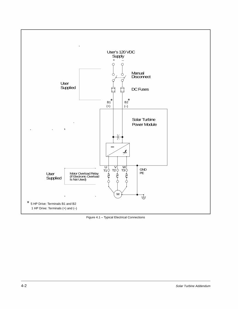
Install the required, user-supplied branch circuit protection fuses according to the applicable local, national, and international codes (e.g., NEC/CEC). The fuses must be installed in the line before the drive input terminals. See figure 4.1. Fuse value recommendations are provided in table 4.1.
4.2 Installing a Required External/Separate Input Disconnect
An input disconnect must be installed in the line before the drive input terminals in accordance with local, national, and international codes (e.g., NEC/CEC). The disconnect should be sized according to the in-rush current as well as any additional loads the disconnect might supply. The trip rating for the inrush current (10-12 times full load current) should be coordinated with that of the input isolation transformer, if used. Refer to instruction manual D2-3360 for additional information.
!ATTENTION: Most codes require that upstream branch protection be provided to protect input power wiring. Failure to observe this precaution could result in severe bodily injury or loss of life.
Table 4.1 – Recommended Input Line Fuse Ratings
Drive HP Rating Input Voltage (+/- 10%) Fuse Rating1
1.Recommended fuse type: UL Class J, 600V, time delay, or equivalent.
1 HP 120 VDC 25A
5 HP 120 VDC 70A
4-2 Solar Turbine Addendum
Figure 4.1 – Typical Electrical Connections
M
U V W
-~
Solar TurbinePower Module
Motor Overload Relay (If Electronic OverloadIs Not Used)
T1 T2 T3
User’s 120 VDCSupply+ _
ManualDisconnect
DC Fuses
UserSupplied
GNDPE
B1(+)
B2(–)
**
* 5 HP Drive: Terminals B1 and B2
1 HP Drive: Terminals (+) and (–)
UserSupplied

Installing Power Wiring 4-3
4.3 Installing Power Wiring from the DC Power Supply to the Drive’s Internal DC Bus Terminals
Use the following steps to connect DC input power to the drive:
Step 1. Wire the DC input power leads by routing them according to drive type. Refer to figures 3.2 and 3.3. Table 4.2 contains the recommended power wiring sizes.
Step 2. Connect the DC input power leads to terminals + and – (1 HP drive) or B1 and B2 (5 HP drive) on the power terminal strip (see figure 4.2).
!ATTENTION: Do not route signal and control wiring in the same conduit with power wiring. This can cause interference with drive operation. Failure to observe this precaution could result in damage to, or destruction of, the equipment.
ATTENTION: If the GV3000/SE drive is connected to an external DC bus, the user is responsible for DC bus short-circuit protection. Failure to observe this precaution could result in damage to, or destruction of, the equipment.
Table 4.2 – Recommended Power Wire Sizes
Type of Wiring Terminals Size of Wire (Maximum)
Output Power U/T1, V/T2, W/T3
12 AWG, 3 mm2 (1 HP)6 AWG, 13 mm2 (5 HP)
DC Input Power +, –
Ground
!ATTENTION: On the 5 HP Solar Turbine drive, the positive DC input must be connected to the (+) terminal. The negative DC input must be connected to the (–) terminal. These terminals cannot be interchanged. Failure to observe this precaution could result in damage to, or destruction of, the equipment.

4-4 Solar Turbine Addendum
Step 3. Tighten the DC input power terminals to the proper torque, as listed in table 4.3.
!ATTENTION: On the 5 HP Solar Turbine drive, the positive DC input must be connected to the (+) terminal. The negative DC input must be connected to the (–) terminal. These terminals cannot be interchanged. Failure to observe this precaution could result in damage to, or destruction of, the equipment.
Figure 4.2 – DC Input Terminals
U/T1 W/T3V/T2
Motor Leads DC NegativeInput
5 HP Drive
1 HP Drive
W/T3V/T2U/T110V 10 COM
Motor LeadsDC BusVolts
B1 B2
DC Inputs
DC PositiveInput
(+) (-)
Table 4.3 – Terminal Tightening Torques
Drive Terminals Maximum Tightening Torque
1 HP All 1.08 Newton-meters (9.5 in-lbs)
5 HP All 13.5 Newton-meters (10 ft-lbs)

Installing Power Wiring 4-5
4.4 Recommended Motor Lead Lengths
The following motor lead lengths are recommended to reduce line disturbances and noise.
Refer to instruction manual D2-3360 for detailed instructions on installing output power wiring.
Table 4.4 – Recommended Motor Lead Lengths
Drive Power Rating
Maximum Lead Length in Feet
Carrier Frequency
2 kHz 4 kHz 8 kHz
1 HP 500 500 500
5 HP 800 500 500

4-6 Solar Turbine Addendum

Troubleshooting the Drive 5-1
CHAPTER 5Troubleshooting the Drive
The GV3000/SE Solar Turbine drive displays alarm and fault codes to signal a problem detected during self tuning or drive operation. These codes are described in instruction manual D2-3359. This chapter provides general troubleshooting safety guidelines and replacement part information that is unique to a 1 HP or 5 HP GV3000/SE Solar Turbine drive. Refer to D2-3359 and to D2-3360 for detailed instructions about troubleshooting a GV3000/SE drive and obtaining standard replacement parts.
5.1 Verifying that DC Bus Capacitors are Discharged
Step 1. Place the input disconnect in the Off position and lock out drive power. Wait five minutes.
Step 2. Remove the drive’s cover.
Step 3. Verify that there is no voltage at the drive’s input power terminals (refer to figure 4.2). This ensures that the DC bus capacitors are discharged.
Step 4. Once the drive has been serviced, reattach the drive’s cover.
Step 5. Reapply input power.
5.2 Replacement Parts
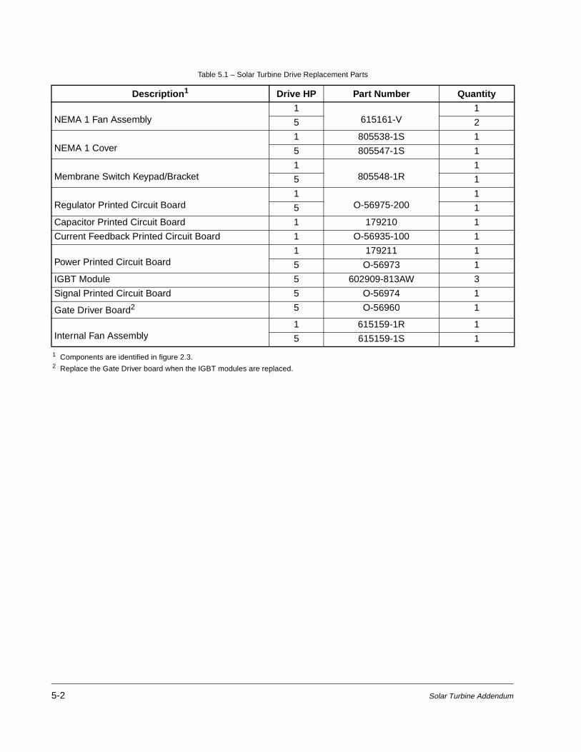
Table 5.1 lists the replacement parts that are available from Reliance Electric. See figures 2.2 and 2.3 for component locations.
!ATTENTION: DC bus capacitors retain hazardous voltages after input power has been disconnected. After disconnecting input power, wait five (5) minutes for the DC bus capacitors to discharge and then check the voltage with a voltmeter to ensure the DC bus capacitors are discharged before touching any internal components. Failure to observe this precaution could result in severe bodily injury or loss of life.
5-2 Solar Turbine Addendum
Table 5.1 – Solar Turbine Drive Replacement Parts
Description1
1 Components are identified in figure 2.3.
Drive HP Part Number Quantity
NEMA 1 Fan Assembly1
615161-V1
5 2
NEMA 1 Cover1 805538-1S 1
5 805547-1S 1
Membrane Switch Keypad/Bracket1
805548-1R1
5 1
Regulator Printed Circuit Board1
O-56975-2001
5 1
Capacitor Printed Circuit Board 1 179210 1
Current Feedback Printed Circuit Board 1 O-56935-100 1
Power Printed Circuit Board1 179211 1
5 O-56973 1
IGBT Module 5 602909-813AW 3
Signal Printed Circuit Board 5 O-56974 1
Gate Driver Board2
2 Replace the Gate Driver board when the IGBT modules are replaced.
5 O-56960 1
Internal Fan Assembly1 615159-1R 1
5 615159-1S 1
Solar Turbine Drive Parameters A-1
APPENDIX ASolar Turbine Drive Parameters
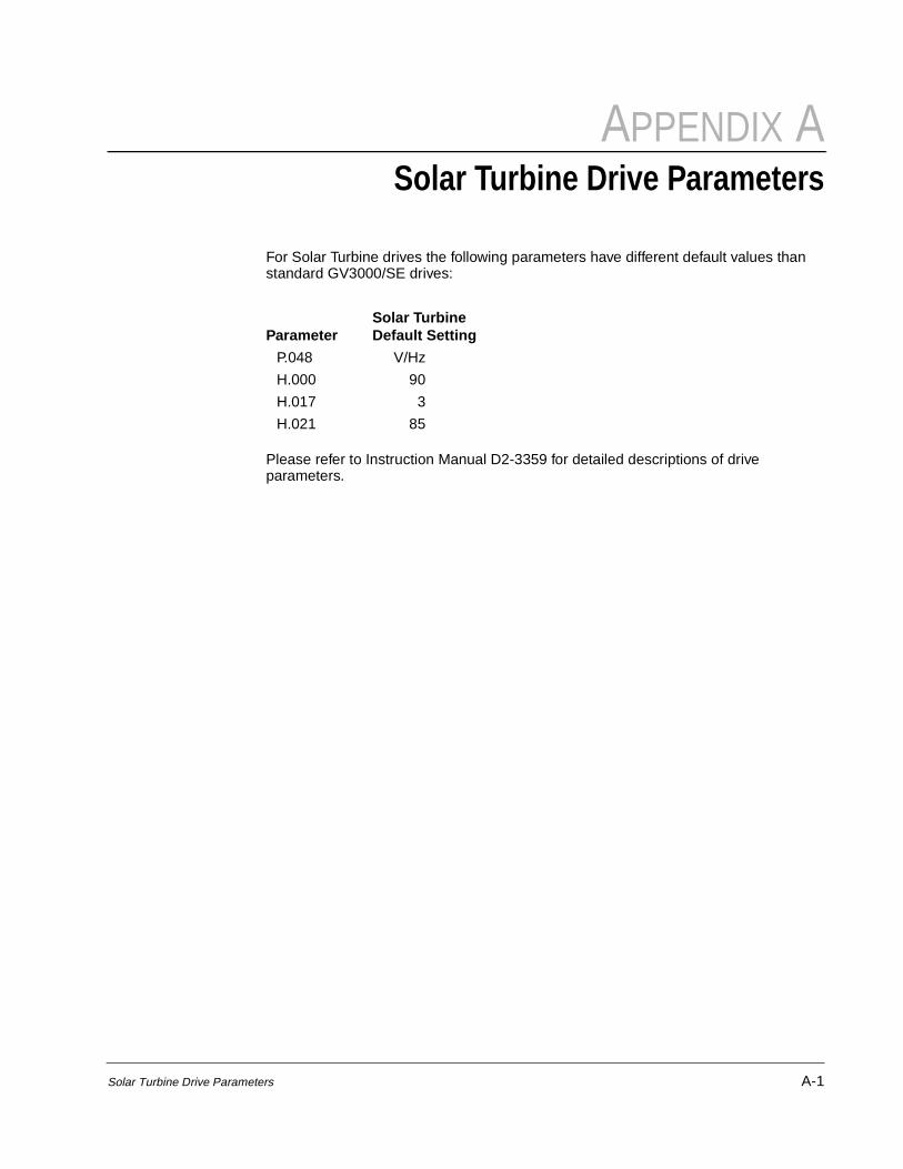
For Solar Turbine drives the following parameters have different default values than standard GV3000/SE drives:
Please refer to Instruction Manual D2-3359 for detailed descriptions of drive parameters.
ParameterSolar TurbineDefault Setting
P.048 V/Hz
H.000 90
H.017 3
H.021 85

A-2 Solar Turbine Appendix

Index Index-1
INDEX
A
About the drive and cabinet, 2-1 to 2-4
B
Branch circuit protection, 4-1
C
Cabinet components, 2-2 to 2-4Cabinet mounting, 3-1 to 3-3Component locations
1 HP drive, 2-25 HP drive, 2-3
Componentsidentifying, 2-2
D
Dimensions, 3-1 to 3-2Drive parameters, default settings, A-1Drive ratings, 2-1
E
Electrical connections, typical, 4-2Enclosure rating, 2-2, 3-2
F
Fuses, 4-1
I
Identifying, 2-1
Identifying drive by model number and ratings, 2-1Input disconnect, 4-1Input terminal identification, 4-4Intended audience, 1-1Introduction, 1-1
M
Model number, 2-1Mounting, 3-1
P
Power wiring, 4-1 to 4-5DC input, 4-2motor lead lengths, 4-5recommended wire sizes, 4-3
R
Replacement parts, 5-1 to 5-2Required manuals, 1-1
T
Terminal tightening torques, 4-4Troubleshooting, 5-1 to 5-2
verifying DC bus capacitors are discharged, 5-1
W
Watts loss rating, verifying, 3-2Weight of drive, 3-1Wire routing, 3-1 to 3-3
cabinet, 3-3

Index-2 Solar Turbine Addendum


U.S. Drives Technical Support Tel: (1) 262.512.8176, Fax: (1) 262.512.2222, Email: [email protected], Online: www.ab.com/support/abdrives
Trademarks not belonging to Rockwell Automation are property of their respective companies. Publication D2-3406-September 1999 Copyright © 1999 Rockwell Automation, Inc. All Rights Reserved. Printed in USA.


![· Steam Turbine C] Fuel Cell Solar/ Photovoltaic C] Biomass Solar/ Photovoltaic Biomass Fuel Type: A. Existing: C] Wind Turbine Hydraulic Turbine Diesel Engine Gas Turbine B. New:](https://img.pdfslide.net/doc/110x75/5eb494634700370587679ab6/steam-turbine-c-fuel-cell-solar-photovoltaic-c-biomass-solar-photovoltaic-biomass.jpg)