Embed Size (px)
Citation preview

8/22/2019 Solaris%2010%20Handbook.pdf
http://slidepdf.com/reader/full/solaris201020handbookpdf 1/198
[email protected] Ph: 040-23757906 / 07, 64526173 [email protected] Version: 3 www.wilshiresoft.com Rev. Dt: 14-Sep-2012
Solaris Handbook

8/22/2019 Solaris%2010%20Handbook.pdf
http://slidepdf.com/reader/full/solaris201020handbookpdf 2/198
[email protected] Ph: 040-23757906 / 07, 64526173 [email protected] Version: 3 www.wilshiresoft.com Rev. Dt: 14-Sep-2012
Index
1. Introduction to Solaris ................................................................................................................... 5
1.1. History of UNIX................................................................................................................................................ 5 1.2. A Brief History of Sun Microsystems ............................................................................................................... 5
1.3. Working with Host ........................................................................................................................................... 6 1.4. Roles of Servers and Clients ........................................................................................................................... 7
2. Solaris Installation ........................................................................................................................ 10
2.1. Solaris Software Installation .......................................................................................................................... 10 2.1.1. The Solaris 10 OE Installation and Upgrade Options ............................................................................. 10 2.1.2. Hardware Requirements for Installation of the Solaris 10 OE ........... .......... ........... .......... ........... .......... .. 11 2.1.3. Solaris OE Software Groups .......... ........... .......... ........... .......... ........... .......... .......... ........... .......... ........... 11 2.1.4. Pre-Installation Information ..................................................................................................................... 13
3. File Systems & Software Management ....................................................................................... 14
3.1. Directory Hierarchy .......... ........... .......... ........... .......... ........... .......... ........... .......... .......... ........... .......... ........... 14 3.1.1. Root Subdirectories ................................................................................................................................ 14 3.1.2. File Components .................................................................................................................................... 14
3.1.3. File Types ............................................................................................................................................... 15 3.1.4. Links ....................................................................................................................................................... 16
3.2. Devices ......................................................................................................................................................... 17 3.2.1. Disk Architecture .................................................................................................................................... 18 3.2.2. Device Naming Convention .................................................................................................................... 20 3.2.3. Managing Devices .................................................................................................................................. 20 3.2.4. Reconfiguring Devices ............................................................................................................................ 21 3.2.5. Disk Partitioning ...................................................................................................................................... 22 3.2.6. Introducing Disk Labels .......................................................................................................................... 23
3.3. Solaris OE File Systems ........... ........... .......... .......... ........... .......... ........... .......... ........... .......... ........... .......... .. 23 3.3.1. Types of File Systems ............................................................................................................................ 23 3.3.2. UFS File System ..................................................................................................................................... 25 3.3.3. File System Maintenance ....................................................................................................................... 29 3.3.4. Monitoring File System Usage ................................................................................................................ 30
3.4. Mounting and Unmounting File Systems ....................................................................................................... 31 3.4.1. Mounting Fundamentals ......................................................................................................................... 31 3.4.2. Volume Management.............................................................................................................................. 33
3.5. Package Administration ................................................................................................................................. 34 3.6. Patch Administration ..................................................................................................................................... 39
4. Startup and Shutdown ................................................................................................................. 41
4.1. Boot PROM ................................................................................................................................................... 41 4.1.1. Boot PROM Fundamentals ..................................................................................................................... 41 4.1.2. Basic Boot PROM Commands ............................................................................................................... 42
4.1.3. Listing NVRAM Parameters .................................................................................................................... 43 4.1.4. Interrupting an Unresponsive System .......... ........... .......... ........... .......... ........... .......... .......... ........... ....... 43 4.2. Perform System Boot and Shutdown ............................................................................................................ 43
4.2.1. SMF and the Boot Process ..................................................................................................................... 43 4.2.2. Run Levels .............................................................................................................................................. 46 4.2.3. SPARC Systems Boot Process .............................................................................................................. 47 4.2.4. SMF and Booting .................................................................................................................................... 51 4.2.5. Run Control Scripts ................................................................................................................................ 51 4.2.6. System Shutdown ................................................................................................................................... 53

8/22/2019 Solaris%2010%20Handbook.pdf
http://slidepdf.com/reader/full/solaris201020handbookpdf 3/198
[email protected] Ph: 040-23757906 / 07, 64526173 [email protected] Version: 3 www.wilshiresoft.com Rev. Dt: 14-Sep-2012
5. Account Management & Security ............................................................................................... 55
5.1. What Are User Accounts and Groups? ......................................................................................................... 55 5.1.1. User Account Components ..................................................................................................................... 55 5.1.2. Where User Account and Group Information Is Stored .......................................................................... 59 5.1.3. Customizing a User’s Work Environment ............................................................................................... 67 5.1.4. Quotas .................................................................................................................................................... 71
5.2. System Security ............................................................................................................................................ 71 5.2.1. Monitoring System Access ..................................................................................................................... 71 5.2.2. Switching Users on a System ................................................................................................................. 73 5.2.3. Controlling System Access ..................................................................................................................... 74 5.2.4. ftp, rlogin, ssh ......................................................................................................................................... 76
6. Printers .......................................................................................................................................... 79
6.1. Printing Terminology ..................................................................................................................................... 79 6.2. Printing in the Solaris Operating System ....................................................................................................... 80 6.3. Administering Printers ................................................................................................................................... 81
7. System Processes & Job Automation ........................................................................................ 87
7.1. Updating System Files .................................................................................................................................. 87
7.2. System Automation with Shell Scripts ........................................................................................................... 87 7.3. Automating Commands with cron and at .......... ........... .......... ........... .......... ........... .......... .......... ........... ......... 87
7.3.1. Scheduling a Repetitive System Task (cron) .......................................................................................... 88 7.3.2. Scheduling a Single System Task (at) .................................................................................................... 90
7.4. Viewing System Processes ........................................................................................................................... 91 8. Backup and Restore ..................................................................................................................... 94
8.1. Fundamentals of Backups ............................................................................................................................. 94 8.2. Types of Backups .......................................................................................................................................... 95 8.3. Types of Backup Devices .............................................................................................................................. 99 8.4. Commands for Copying File Systems ......................................................................................................... 103 8.5. Backup Device Names ................................................................................................................................ 108
9. Network Basics ........................................................................................................................... 112 9.1. TCP/IP ......................................................................................................................................................... 113 9.2. Network Services ........................................................................................................................................ 116
10. Swap, Core & Crash Files ........................................................................................................ 124
10.1. Virtual Memory Concepts .......................................................................................................................... 124 10.2. Configuring Swap ...................................................................................................................................... 125 10.3. Core Files and Crash Dumps .................................................................................................................... 125
10.3.1. Core Files ........................................................................................................................................... 125 10.3.2. Crash Dumps ...................................................................................................................................... 127
11. Network File Systems .............................................................................................................. 130
11.1. NFS terminology ........................................................................................................................................ 130
11.2. Remote Procedure Call (RPC) .................................................................................................................. 130 11.3. NFS Commands ........................................................................................................................................ 131 11.4. NFS Daemons ........................................................................................................................................... 133 11.5. Commands for Troubleshooting NFS Problems ........................................................................................ 135 11.6. Autofs ........................................................................................................................................................ 136
11.6.1. Autofs Features .................................................................................................................................. 136 11.6.2. Autofs Maps ........................................................................................................................................ 137 11.6.3. How Autofs Works .............................................................................................................................. 140
12. Solaris Volume Manager .......................................................................................................... 142

8/22/2019 Solaris%2010%20Handbook.pdf
http://slidepdf.com/reader/full/solaris201020handbookpdf 4/198
[email protected] Ph: 040-23757906 / 07, 64526173 [email protected] Version: 3 www.wilshiresoft.com Rev. Dt: 14-Sep-2012
12.1. Introduction to Storage Management ........................................................................................................ 142 12.2. Introduction to Solaris Volume Manager ................................................................................................... 143 12.3. Solaris Volume Manager Requirements .................................................................................................... 143 12.4. SVM Configuration .................................................................................................................................... 145 12.5. Overview of RAID-0 Volumes .......... .......... ........... .......... ........... .......... .......... ........... .......... ........... .......... .. 150 12.6. Overview of RAID-1 (Mirror) Volumes ....................................................................................................... 151 12.7. Overview of RAID-5 Volumes .......... .......... ........... .......... ........... .......... .......... ........... .......... ........... .......... .. 152 12.8. Overview of Hot Spares and Hot Spare Pools .......................................................................................... 153 12.9. Introduction to Disk Sets ........................................................................................................................... 154
13. RBAC and Syslog ..................................................................................................................... 156
13.1. RBAC ........................................................................................................................................................ 156 13.2. System Messaging .................................................................................................................................... 159
13.2.1. Syslog Function Fundamentals .......................................................................................................... 159 13.2.2. Customizing System Message Logging .............................................................................................. 159
14. Naming Services ....................................................................................................................... 161
14.1. Name Service concept .............................................................................................................................. 161 14.2. Solaris Naming Services ........................................................................................................................... 161
14.3. The Name Service Switch ......................................................................................................................... 163 14.4. Domain Name Service .............................................................................................................................. 164 14.5. Network Information Service ..................................................................................................................... 169
15. Advanced Installations ............................................................................................................ 174
15.1. Solaris Containers ..................................................................................................................................... 174 15.1.1. Resource Management ...................................................................................................................... 174 15.1.2. Solaris Zones ...................................................................................................................................... 174
15.2. Custom JumpStart Introduction ................................................................................................................. 177 15.3. Solaris Flash Introduction .......................................................................................................................... 178
16. Performance Tuning ................................................................................................................. 180
17. Miscellaneous ........................................................................................................................... 189
17.1. Dynamic Host Configuration Protocol .......... ........... .......... .......... ........... .......... .......... ........... ........... .......... 189 17.2. Samba ....................................................................................................................................................... 192 17.3. Apache ...................................................................................................................................................... 193
Appendix .............................................................................................................................................. I

8/22/2019 Solaris%2010%20Handbook.pdf
http://slidepdf.com/reader/full/solaris201020handbookpdf 5/198
Chapter 1 – Introduction to Solaris Page 5 of 198
[email protected] Ph: 040-23757906 / 07, 64526173 [email protected] Version: 3 www.wilshiresoft.com Rev. Dt: 14-Sep-2012
1. Introduction to Solaris
1.1. History of UNIX
UNIX originated as a research project at AT&T Bell Labs in 1969. In 1976, it was made available at no charge touniversities and thus became the basis for many operating systems classes and academic research projects.
As the UNIX OS offered by AT&T evolved and matured, it became known as System V (five) UNIX. As thedeveloper of UNIX, AT&T licensed other entities to produce their own versions of the UNIX OS. One of the morepopular of these licensed UNIX variants was developed by The University of California at Berkeley Computer Science Research Group. The Berkeley UNIX variant was dubbed Berkeley Software Distribution (BSD) UNIX.
The BSD version of UNIX rapidly incorporated networking, multiprocessing, and other innovations, whichsometimes led to instability. In an academic environment these temporary instabilities were not considered major problems, and researchers embraced the quickly evolving BSD UNIX environment. In contrast, corporatecomputing centers were wary of converting to OS with a history of instability.
Unlike BSD UNIX, AT&Ts System V UNIX offered stability and standardization. New capabilities were introducedat a slower rate, often after evaluating the results of introducing the same capabilities in the BSD UNIX releases.Corporate computing centers tended to favor the stability of AT&Ts version of UNIX over that of BSD UNIX.
1.2. A Brief History of Sun MicrosystemsSun Microsystems Computer Corporation was one of the manufacturers at the forefront of the distributedcomputing revolution. The company’s first workstations employed microprocessors from the Motorola MC68k chipfamily. Sun Microsystems founders believed that a UNIX operating system would be the most desirable option for their new line of workstations. The early Sun systems ran an operating system called SunOS (Sun OperatingSystem). SunOS was based on the BSD UNIX distribution.
NOTE: About Sun Microsystems, Inc. (NASDAQ: SUNW)
It was started in the year 1982 and and its singular vision is -- "The Network Is the Computer." It is a leadingprovider of industrial-strength hardware, software and services that make the Net work. Sun can be found in morethan 100 countries and on the Web at http://sun.com
Enter the SPARC
Although the systems based on microprocessor chips were faster than many mainframes, there was still room for
improvement. Sun promptly began developing its own microprocessor. In the 1980s Sun introduced a ReducedInstruction Set Computer (RISC) chip called the Scalable Processor ARChitecture (SPARC) processor. The firstimplementation of the SPARC chip ran at twice the speed of the fastest MC68k-based systems Sun wasproducing at the time.
The SPARC processor chip allowed Sun to produce very powerful, inexpensive, desktop workstations. TheSPARC systems also ran the SunOS operating system, thus preserving customers’ software developmentinvestments. Many other workstation manufacturers were delivering operating systems based on AT&Ts SystemV release 3 operating system standards. Suns customer base had to decide between the Sun BSD basedoperating system and competitors System V based offerings.
Suns New Operating System
In the late 1980s Sun announced plans to develop a new operating system based on the AT&T System V release4 UNIX. The new OS is called Solaris. In order to make the progression of OS release numbers easy toremember, Suns original OS is still known as SunOS version 4.X. The new Solaris OS was referred to as SunOS
5.X. In 1999, Sun released a new version of the Solaris OS named Solaris 7 (SunOS 5.7), and so on.
The Solaris OS presented two problems for Sun customers. The first problem was that many applicationsavailable under BSD UNIX were not available under System V UNIX. Software vendor had to expend great effortto recode portions of respective applications in order to make them operate under Solaris.
The second problem presented by Solaris to customers was that many BSD-fluent system administrators had noexperience with a System V OS. Although most user-level commands are similar under SunOS and Solaris, thesystem administration commands are very different. Many of the “old reliable” commands from BSD -based UNIXare missing from Solaris. Next, new commands with more functionality replaced these BSD commands. Thearchitecture of the OS is also very different under Solaris. Access to and management of system devices under

8/22/2019 Solaris%2010%20Handbook.pdf
http://slidepdf.com/reader/full/solaris201020handbookpdf 6/198
Chapter 1 – Introduction to Solaris Page 6 of 198
[email protected] Ph: 040-23757906 / 07, 64526173 [email protected] Version: 3 www.wilshiresoft.com Rev. Dt: 14-Sep-2012
Solaris is foreign to BSD sys-admins. SunOS is the heart of the Solaris OE. Like all OSs, SunOS is a collection of software that manages system resources and schedules system operations.
Command Line Interface
A command line interface (CLI) enables users to type commands in a terminal or console window to interact withan operating system. Users respond to a visual prompt by typing a command on a specified line, and receive aresponse back from the system. Users type a command or series of commands for each task they want to
perform.Graphical User Interfaces
A graphical user interface (GUI) uses graphics, along with a keyboard and a mouse, to provide an easy-to-useinterface to a program. A GUI provides windows, pull-down menus, buttons, scrollbars, ic onic images, wizards,other icons, and the mouse to enable users to interact with the operating system or application. The Solaris 10operating environment supports two GUIs, the Common Desktop Environment (CDE) and the GNOME desktop.
Common Desktop Environment
The Common Desktop Environment (CDE) provides windows, workspaces, controls, menus, and the Front Panelto help you organize and manage your work. You can use the CDE GUI to organize your files and directories,read, compose and send email, access files, and manage your system.
GNOME Desktop
GNOME (GNU Network Object Model Environment) is a GUI and set of computer desktop applications. You canuse the GNOME desktop, panel, applications, and tool set to customize your working environment and manageyour system tasks. GNOME also provides an application set, including a word processor, a spreadsheet program,a database manager, a presentation tool, a Web browser, and an email program.
1.3. Working with Host
Host is another word for a computer. The term host comes from the notion that the computer hardware hosts theOS and applications. The hardware is like a house in which the “guests”(programs) live. In order to distinguishone computer from another, hosts are assigned names, or hostnames. To continue the house metaphor, thehostname would be the systems address. In the Solaris OE, the system administrator assigns hostnames.
Assigning Hostnames
Hostnames usually follow a uniform naming convention. An advantage of the naming convention is to make iteasier to keep track of which hosts belong to which organizations. Another advantage of the naming scheme is
that it makes it easy for system users to remember the name when reporting problems or describing tasks.
192.168.0.0. Network
Alice Humpty Dumpty Queen
The illustration shows four hosts connected to a network. The host named Queen is a large-capacity computer that provides network services to other computers connected to the network. These are frequently referred to as
datacenters or servers. The hosts named Alice, Humpty, and Dumpty are desktop workstations that use thenetwork services provided by Queen. Desktop workstations are often referred to as clients.
Assigning network addresses
Along with hostname, the sys-admin assigns each host an Internet Address. Each Ethernet interface on a hostalso has a Ethernet address, built into the Ethernet hardware. The address resolution protocol (ARP) maps theInternet addresses to Ethernet addresses.
Internet Address

8/22/2019 Solaris%2010%20Handbook.pdf
http://slidepdf.com/reader/full/solaris201020handbookpdf 7/198
Chapter 1 – Introduction to Solaris Page 7 of 198
[email protected] Ph: 040-23757906 / 07, 64526173 [email protected] Version: 3 www.wilshiresoft.com Rev. Dt: 14-Sep-2012
The Internet address, similar to a telephone number, enables hosts to communicate with one another. For example, in the case of a long distance telephone call, the caller dials the area code, exchange number, and linenumber in order to communicate with a specific telephone location. In the same way, a hosts Internet addressdescribes where a host is on the Internet, which in turn allows network traffic to be directed to the host.
In the previous illustration, the hosts are connected to the Internet network number 192.168.0.0. The Internetaddress assigned to a host can and often changes over the hosts’ lifetime.
Host Ethernet Address An Ethernet address functions like a passport number in that it is unique and permanent hardware addressassigned by the hardware manufacturer. Hosts are identified via such addresses on the Ethernet, which in turnenables them to communicate.
1.4. Roles of Servers and Clients
Servers and clients are two types of hosts in a network environment. A server is a process or program thatprovides services to hosts on a network. If a host runs one or more server processes, it can also be referred to asa server. A client is both a “process” that uses services provided by the server and a host that runs a clientprocess.
Process here refers to the program currently running. It is possible to have multiple instances of a single program,each separately serving different clients. The MTA, sendmail, is a good example.
Examples for different types of “servers” are: file servers (share disk storage with hosts), application servers,applications, boot servers, and boot services. Print servers attach printers and provide network printing services.
A typical file server providing html pages for a client
Host Configurations
Two standard host configurations are
1. Standalone
2. Diskless
NOTE: Host Configuration refers to how the host boots.Standalone
Standalone hosts boot up independently of network services. We even have “Networked Standalone” which refersto a standalone host connected to a network and they are up and running independent of the state of the network.
NOTE: In order for a host to boot into the multi-user state, it must be able to locate the / and swap filesystems.The root contains the boot code, system files, and directories necessary for host operation. Swap is used for virtual memory, which extends the hosts available memory.
Diskless Client
These are totally dependent on the network services to boot and operate. A diskless clients root, swap and usr are supplied by a client server on the network. Advantages of this configuration include reduced equipment cost,and centralized services and a drawback is the network load.

8/22/2019 Solaris%2010%20Handbook.pdf
http://slidepdf.com/reader/full/solaris201020handbookpdf 8/198
Chapter 1 – Introduction to Solaris Page 8 of 198
[email protected] Ph: 040-23757906 / 07, 64526173 [email protected] Version: 3 www.wilshiresoft.com Rev. Dt: 14-Sep-2012
For example, the /export filesystem of the “boot server” contains a directory known as root. The /export/rootdirectory contains a sub-directory for each diskless client supported by the server.
The diskless client swap is used in a fashion similar to the root area. Special “swap files,” one per supporteddiskless client, are located under the /export/swap file system. Take a look at the illustration:
192.168.0.0 Network
Diskless Boot Server
Client Disk
Diskless Client and Boot Server Configuration
Host
Disk
A standalone host configuration
root
swap
/export/root
root, swap

8/22/2019 Solaris%2010%20Handbook.pdf
http://slidepdf.com/reader/full/solaris201020handbookpdf 9/198
Chapter 1 – Introduction to Solaris Page 9 of 198
[email protected] Ph: 040-23757906 / 07, 64526173 [email protected] Version: 3 www.wilshiresoft.com Rev. Dt: 14-Sep-2012
Solaris Release History
Date Release Notes
1982 Sun UNIX 0.7 First version of Sun’s UNIX, based on 4.BSD from UniSoft. Bundled with the Sun-1, Sun’s first workstation based on the Motorola 68k processor;Sun Windows GUI.
1983 SunOS 1.0 Sun-2 workstation, 68010 based.
1985 SunOS 2.0 NFS implemented.
1988 SunOS 4.0 New virtual memory system integrates the file system cache with the memory system.The first SPARC-based Sun workstation, the Sun-4. Support for the Intel-based Sun386i.
1990 SunOS 4.1 Supports the SPARCstation1+, IPC, SLC.OpenWindows graphics environment.
1992 Solaris 2.0 Solaris 2.x is born, based on a port of System V Release 4.0.Uniprocessor only.First release of Solaris 2, version 2.0, is a desktop-only developers release.
1993 Solaris 2.1 Four-way symmetric multiprocessing (SMP).
1993 Solaris 2.2 Large (>2 Gbyte) file system support.
SPARCserver 1000 and SPARCcenter 2000 (sun4d architecture).
1993 Solaris 2.1-x86 Solaris ported to the Intel i386 architecture.
1993 Solaris 2.3 8-way SMP.Device power management and system suspend/resume functionality added.
1994 Solaris 2.4 20-way SMP.Caching file system (cachefs).CDE windowing system.
1995 Solaris 2.5 NFS Version 3.Supports sun4u (UltraSPARC) architecture UltraSPARC-I-based products introduced – the Ultra-1 workstation.
1996 Solaris 2.6 Added support for large (> 2 Gbyte files).UFS direct I/O.
1998 Solaris 7 64-bit kernel and process address space.Logging UFS integrated.
2000 Solaris 8 SMC 2.0Diskless Client ManagementRBAC
2001 Solaris 9 Built in SVMSecure ShellIntegration of directory server and LDAP server
2005 Solaris 10 Solaris ContainersSolaris Service Manager Dynamic Tracing

8/22/2019 Solaris%2010%20Handbook.pdf
http://slidepdf.com/reader/full/solaris201020handbookpdf 10/198
Chapter 2 – Solaris Installation Page 10 of 198
[email protected] Ph: 040-23757906 / 07, 64526173 [email protected] Version: 3 www.wilshiresoft.com Rev. Dt: 14-Sep-2012
2. Solaris Installation
2.1. Solaris Software Installation
2.1.1. The Solaris 10 OE Installation and Upgrade Options
There are a number of ways to install the Solaris 10 OE on your system. They include:
1. Solaris installation program
2. Solaris installation program over the network
3. Custom Jumpstart
4. Solaris Flash archives
5. WAN boot
6. Solaris Live Upgrade
7. Solaris Zones
Solaris Installation over the network
Network installations enable you to install the Solaris software from the system, called an install server that has
access to the Solaris 10 disc images. You copy the contents of the Solaris 10 DVD or CD media to the installserver’s hard disk. Then, you can install the Solaris software from the network by using any of the Solarisinstallation methods.
Custom JumpStart Installation
The custom JumpStart installation method is a command –line interface that enables you to automatically install or upgrade several systems, based on profiles that you create. The profiles define specific software installationrequirements. You can also incorporate shell scripts to include preinstallation and postinstallation tasks. Youchoose which profile and scripts to use for installation or upgrade. The custom JumpStart installation methodinstalls or upgrades the system, based on the profile and scripts that you select. Also, you can use a sysidcfg fileto specify configuration information so that the custom JumpStart installation is completely hands-off.
Solaris Flash Archives
The Solaris Flash installation feature enables you to use a single reference installation of the Solaris OS on asystem, which is called the master system. Then, you can replicate that installation on a number of systems,
which are called clone systems. You can replicate clone systems with a Solaris Flash initial installation thatoverwrites all files on the system or with a Solaris Flash update that only includes the differences between twosystem images. A differential update changes only the files that are specified and is restricted to systems thatcontain software consistent with the old master image.
WAN boot
The WAN boot installation method enables you to boot and install software over a wide area network (WAN) byusing HTTP. By using WAN boot, you can install the Solaris OS on SPARC based systems over a large publicnetwork where the network infrastructure might be untrustworthy. You can use WAN boot with security features toprotect data confidentiality and installation image integrity.
The WAN boot installation method enables you to transmit an encrypted Solaris Flash archive over a publicnetwork to a remote SPARC based client. The WAN boot programs then install the client system by performing acustom JumpStart installation. To protect the integrity of the installation, you can use private keys to authenticateand encrypt data. You can also transmit your installation data and files over a secure HTTP connection by
configuring your systems to use digital certificates.
Solaris Live Upgrade
Solaris Live Upgrade provides a method of upgrading a system while the system continues to operate. While your current boot environment is running, you can duplicate the boot environment, then upgrade the duplicate. Or,rather than upgrading, you can install a Solaris Flash archive on a boot environment. The original systemconfiguration remains fully functional and unaffected by the upgrade or installation of an archive. When you areready, you can activate the new boot environment by rebooting the system. If a failure occurs, you can quicklyrevert to the original boot environment with a simple reboot. This switch eliminates the normal downtime of thetest and evaluation process.

8/22/2019 Solaris%2010%20Handbook.pdf
http://slidepdf.com/reader/full/solaris201020handbookpdf 11/198
Chapter 2 – Solaris Installation Page 11 of 198
[email protected] Ph: 040-23757906 / 07, 64526173 [email protected] Version: 3 www.wilshiresoft.com Rev. Dt: 14-Sep-2012
Solaris Zones
After the Solaris OS is installed, you can install and configure zones. In a zones environment, the global zone isthe single instance of the operating system that is running and is contained on every Solaris system. The globalzone is both the default zone for the system and the zone that is used for system-wide administrative control.
A non-global zone is a virtualized operating system environment. Solaris Zones are a software partitioningtechnology used to virtualize operating system services and provide an isolated and secure environment for
running applications. When you create a zone, you produce an application execution environment in whichprocesses are isolated from all other zones. This isolation prevents processes that are running in one zone frommonitoring or affecting processes that are running in any other zones. Even a process running in a non-globalzone with superuser credentials cannot view or affect activity in any other zones. A process running in the globalzone with superuser credentials can affect any process in any zone.
The global zone is the only zone from which a non-global zone can be configured, installed, managed, or uninstalled. Only the global zone is bootable from the system hardware. Administration of the systeminfrastructure, such as physical devices, routing, or dynamic reconfiguration (DR), is only possible in the globalzone. Appropriately privileged processes running in the global zone can access objects associated with any or allother zones.
2.1.2. Hardware Requirements for Installation of the Solaris 10 OE
Perform the following tasks before you begin your installation.
SPARC systems
1. Ensure that you have the following media.
a. For a DVD installation, the Solaris 10 Operating System for SPARC platforms DVD
b. For a CD installation, use Solaris 10 Software CDs.
2. Verify that your system meets the minimum requirements.
3. Your system should meet the following requirements.
a. Memory – 128 Mbytes or greater
b. Disk space – 12 Gbytes or greater
c. Processor speed – 200 MHz or greater
x86 systems
1. Ensure that you have the following media.
a. If you are installing from a DVD, use the Solaris 10 Operating System for x86
platforms DVD.b. If you are installing from CD media, use Solaris 10 Software CDs.
c. Check your system BIOS to make sure you can boot from CD or DVD media.
2. Verify that your system meets the minimum requirements.
3. Your system should meet the following requirements.
a. Memory – 128 Mbytes or greater
b. Disk space – 12 Gbytes or greater
c. Processor speed – 120 MHz or greater with hardware floating point
2.1.3. Solaris OE Software Groups
Software groups are collections of Solaris OE software packages. Each software group includes support for different functions and hardware drivers. When you are planning disk space, remember that you can add or
remove individual software packages from the software group that you select.
The Solaris OE is made up of six software groups:
1. Reduced Network Support Software Group
2. Core System Support Software Group
3. End User Solaris Software Group
4. Developer Solaris Software Group
5. Entire Distribution
6. Entire Distribution plus OEM Support

8/22/2019 Solaris%2010%20Handbook.pdf
http://slidepdf.com/reader/full/solaris201020handbookpdf 12/198
Chapter 2 – Solaris Installation Page 12 of 198
[email protected] Ph: 040-23757906 / 07, 64526173 [email protected] Version: 3 www.wilshiresoft.com Rev. Dt: 14-Sep-2012
The table summarizes the different Software Groups and their space requirements
Software Group Description RecommendedDisk Space
Entire Solaris SoftwareGroup Plus OEM Support
Contains the packages for the Entire Solaris Software Groupplus additional hardware drivers, including drivers for hardwarethat is not on the system at the time of installation.
6.7 Gbytes
Entire Solaris software Group Contains the packages for the Developer Solaris SoftwareGroup and additional software that is needed for servers.
6.5 Gbytes
Developer Solaris SoftwareGroup
Contains the packages for the End User Solaris SoftwareGroup plus additional support for software development. Theadditional software development support includes libraries,include files, man pages, and programming tools. Compilersare not included.
6.0 Gbytes
End User Solaris SoftwareGroup
Contains the packages that provide the minimum code that isrequired to boot and run a networked Solaris system and theCommon Desktop Environment.
5.0 Gbytes
Core System SupportSoftware Group
Contains the packages that provide the minimum code that isrequired to boot and run a networked Solaris system.
2.0 Gbytes
Reduced Network SupportSoftware Group
Contains the packages that provide the minimum code that isrequired to boot and run a Solaris system with limited network
service support. The Reduced Network Support SoftwareGroup provides a multiuser text-based console and systemadministration utilities.This software group also enables the system to recognizenetwork interfaces, but does not activate network services.
2.0 Gbytes
Installation Media
This release has one installation DVD and several installation CDs. The Solaris 10 Operating System DVDincludes the content of all the installation CDs.
Solaris Software 1 – This CD is the only bootable CD. From this CD, you can access both the Solaris installationgraphical user interface (GUI) and the console-based installation. This CD also enables you to install selectedsoftware products from both the GUI and the console-based installation.
For both CD and DVD media, the GUI installation is the default (if your system has enough memory). However,you can specify a console-based installation with the text boot option. The installation process has beensimplified, enabling you to select the language support at boot time, but select locales later.
To install the OS, simply insert the Solaris Software - 1 CD or the Solaris Operating System DVD and type one of the following commands.
For the default GUI installation (if system memory permits), type boot cdrom.
For the console-based installation, type boot cdrom - text.
Accessing the GUI or Console-based Installations
You can choose to install the software with a GUI or with or without a windowing environment. Given sufficientmemory, the GUI is displayed by default. If the memory is insufficient for the GUI, other environments aredisplayed by default. You can override defaults with the nowin or text boot options. But, you are limited by theamount of memory in your system or by installing remotely. Also, if the Solaris installation program does notdetect a video adapter, the program is automatically displayed in a console-based environment. The following
table describes these environments and lists minimal memory requirements for displaying them.Detailed descriptions for each installation option are as follows:
Installation with 128 – 383 MB minimal memory
This option contains no graphics, but provides a window and the ability to open other windows. This optionrequires a local or remote DVD-ROM or CD-ROM drive or network connection, video adapter, keyboard, andmonitor. If you install by using the text boot option and have enough memory, you are installing in a windowingenvironment. If you are installing remotely through a tip line or by using the nowin boot option, you are limited tothe console-based installation.

8/22/2019 Solaris%2010%20Handbook.pdf
http://slidepdf.com/reader/full/solaris201020handbookpdf 13/198
Chapter 2 – Solaris Installation Page 13 of 198
[email protected] Ph: 040-23757906 / 07, 64526173 [email protected] Version: 3 www.wilshiresoft.com Rev. Dt: 14-Sep-2012
Installation with 384 MB memory or greater
This option provides windows, pull-down menus, buttons, scrollbars, and iconic images. A GUI requires a local or remote DVD-ROM or CD-ROM drive or network connection, video adapter, keyboard, and monitor.
2.1.4. Pre-Installation InformationConsider the following general guidelines while planning an installation:
1. Allocate additional space in the /var file system if you plan to have your system support printing or mail.
2. Allocate double the amount of physical memory in the /var file system if you plan to use the crash dumpfeature savecore on your system.
3. Allocate additional space in the /export file system if you plan to provide a home directory file system for users on the Solaris 10 OE.
4. Allocate space for the Solaris software group you want to install.
5. Allocate an additional 30 percent more disk space for each file system that you create, and create aminimum number of file systems. This leaves room for upgrades to future software releases.
Note – By default, the Solaris OE installation methods create only the / (root) file system and the swap partition. Allocate additional disk space for additional software or third-party software.

8/22/2019 Solaris%2010%20Handbook.pdf
http://slidepdf.com/reader/full/solaris201020handbookpdf 14/198
Chapter 3 – File Systems & Software Management Page 14 of 198
[email protected] Ph: 040-23757906 / 07, 64526173 [email protected] Version: 3 www.wilshiresoft.com Rev. Dt: 14-Sep-2012
3. File Systems & Software Management
3.1. Directory Hierarchy
3.1.1. Root Subdirectories
A file system can be defined in two ways.
1. One is at the operating system level and the other at the user level.
2. At the OS level a file system is a data structure of a disk slice or other media storage device, which allowsfor efficient data storage and management
And at the user level, a file system is nothing but - hierarchical collection of directories, sub-directories and files. And this hierarchy is called the Directory Hierarchy.
Solaris OE Directory Hierarchy (It’s not a complete tree)
3.1.2. File Components
All files in the Solaris OE make use of a f ile name and a record called an inode. Most files also make use of datablocks. In general, a file name is associated with an inode, and an inode provides access to data blocks.
File Names
File names are the objects most often used to access and manipulate files. A file must have a name that isassociated with an inode.
InodesInodes are the objects the Solaris OE uses to record information about a file. In general, inodes contain two parts.First, inodes contain information about the file, including its owner, its permissions, and its size. Second, inodescontain pointers to data blocks associated with the file. Inodes are numbered, and each file system contains itsown list of inodes. When a new file system is created, a complete list of new inodes is also created in that filesystem.
Data Blocks
Data blocks are units of disk space that are used to store data. Regular files, directories, and symbolic links makeuse of data blocks. Device files do not hold data.

8/22/2019 Solaris%2010%20Handbook.pdf
http://slidepdf.com/reader/full/solaris201020handbookpdf 15/198
Chapter 3 – File Systems & Software Management Page 15 of 198
[email protected] Ph: 040-23757906 / 07, 64526173 [email protected] Version: 3 www.wilshiresoft.com Rev. Dt: 14-Sep-2012
3.1.3. File Types
There are four main file types
Regular or ordinary files
Directories
Symbolic links
Device files
Use the ls command to distinguish different file types from one another. The character in the first column of information that the ls – l command displays indicates the file type. The following examples, taken from a
SPARC technology Ultra 10 workstation, show partial listings of directories that contain a variety of different filetypes:
# cd /etc
# ls -l |more
total 588
lrwxrwxrwx 1 root root 14 Oct 22 11:05 TIMEZONE-> ./default/init
drwxr-xr-x 6 root other 512 Oct 22 12:10 X11
drwxr-xr-x 2 adm adm 512 Oct 22 12:41 acct
lrwxrwxrwx 1 root root 14 Oct 22 11:21 aliases -> ./mail/aliases
drwxr-xr-x 7 root bin 512 Oct 22 12:47 apache
drwxr-xr-x 2 root bin 512 Oct 22 12:43 apache2
drwxr-xr-x 2 root other 512 Oct 22 11:53 apoc
-rw-r--r-- 1 root bin 194 Oct 22 11:17 auto_home
-rw-r--r-- 1 root bin 248 Oct 22 11:17 auto_master
(output truncated)
# cd /devices/pci@1f,0/pci@1,1/ide@3
# ls -l|more
total 4
drwxr-xr-x 2 root sys 512 Oct 22 13:11 dad@0,0
brw-r----- 1 root sys 136, 8 Oct 22 13:27 dad@0,0:a
crw-r----- 1 root sys 136, 8 Oct 22 15:25 dad@0,0:a,raw
brw-r----- 1 root sys 136, 9 Oct 22 13:46 dad@0,0:b
(output truncated)
The character in the first column identifies each file type, as follows:
- Regular files
d Directories
l Symbolic links
b Block-special device files
c Character-special device files

8/22/2019 Solaris%2010%20Handbook.pdf
http://slidepdf.com/reader/full/solaris201020handbookpdf 16/198
Chapter 3 – File Systems & Software Management Page 16 of 198
[email protected] Ph: 040-23757906 / 07, 64526173 [email protected] Version: 3 www.wilshiresoft.com Rev. Dt: 14-Sep-2012
Regular File
The above illustrate what a regular file contains and how they can be created.
Directory File
Directories hold a list of file names and the inode numbers associated with them.
3.1.4. Links
There are 2 types of links:
Symbolic link
Hard Link
Symbolic Link:
A symbolic link is a file that points to another file. They contain the path name of the file to which they arepointing. The size of a symbolic link always matches the number of characters in the path name it contains. In thefollowing example, the symbolic link called /dev/dsk/c0t0d0s0 points to the physical device
./devices/pci@1f, 0/pci@1, 1/ide@3/dad@0, 0:a. The size of the symbolic link is 46 bytes because
the path name ./devices/pci@1f, 0/pci@1, 1/ide@3/dad@0, 0:a contains 46 characters.
# cd /dev/dsk
# ls -l c0t0d0s0
lrwxrwxrwx 1 root root 46 Oct 22 11:22 c0t0d0s0 -> ../../devices/
pci@1f,0/pci@1,1/ide@3/dad@0,0:a
Creating a Symbolic Link:
The ln command with – s option is used to create symbolic links

8/22/2019 Solaris%2010%20Handbook.pdf
http://slidepdf.com/reader/full/solaris201020handbookpdf 17/198
Chapter 3 – File Systems & Software Management Page 17 of 198
[email protected] Ph: 040-23757906 / 07, 64526173 [email protected] Version: 3 www.wilshiresoft.com Rev. Dt: 14-Sep-2012
# ln -s file1 link1
# ls -l link1
lrwxrwxrwx 1 root root 5 Oct 22 15:56 link1 -> file1
From the output, we see that link1 is pointing towards file1. (Symbolic links are similar to short cuts inWindows).
HARD LINKS
A hard link is the association between a file name and an inode. Information in each inode keeps count of thenumber of file names associated with it. This is called a link count. In the output from the ls -l command, the
link count appears between the column of file permissions and the column identifying the owner. In the followingexample, the file called alice uses one hard link.
# cd dir1
# touch alice
# ls -l
total 0
-rw-r--r-- 1 root root 0 Oct 22 16:18 alice
A new hard link for a file name increments the link count in the associated inode. For example:
# ln alice humpty-dumpty
# ls -ltotal 0
-rw-r--r-- 2 root root 0 Oct 22 16:18 alice
-rw-r--r-- 2 root root 0 Oct 22 16:18 humpty-dumpty
# ls -li
total 0
16601 -rw-r--r-- 2 root root 0 Oct 22 16:18 alice
16601 -rw-r--r-- 2 root root 0 Oct 22 16:18 humpty-dumpty
# find . -inum 16601
./alice
./humpty-dumpty
The ln command creates new hard links to regular files. Unlike symbolic links, hard links cannot span filesystems.
3.2. Devices
A device file provides access to a device. The inode information of device files holds numbers that point to thedevices. For example:
# cd /devices/pci@1f,0/pci@1
# ls -l
total 4
drwxr-xr-x 2 root sys 512 Oct 22 13:11 pci@2
crw------- 1 root sys 115, 255 Oct 22 16:04 pci@2:devctl
drwxr-xr-x 2 root sys 512 Oct 22 13:11 scsi@1
crw------- 1 root sys 50, 0 Oct 22 16:04 scsi@1:devctlcrw------- 1 root sys 50, 1 Oct 22 16:04 scsi@1:scsi
A long listing shows 2 numbers:
major number
minor number
A major device number identifies the specific device driver required to access a device. A minor device number identifies the specific unit of the type that the device driver controls.

8/22/2019 Solaris%2010%20Handbook.pdf
http://slidepdf.com/reader/full/solaris201020handbookpdf 18/198
Chapter 3 – File Systems & Software Management Page 18 of 198
[email protected] Ph: 040-23757906 / 07, 64526173 [email protected] Version: 3 www.wilshiresoft.com Rev. Dt: 14-Sep-2012
Device files fall into two categories: character-special devices and block-special devices. Character-specialdevices are also called character or raw devices. Block-special devices are often called block devices. Devicefiles in these two categories interact with devices differently.
Character-Special Device Files
The file type “c” identifies character -special device files. For disk devices, character-special device files call for input/output (I/O) operations based on the disk’s smallest addressable unit, a sector. Each sector is 512 bytes insize.
Block-Special Device Files
The file type “b” identifies block-special device files. For disk devices, block-special device files call for I/Ooperations based on a defined block size. The block size depends on the particular device, but for UNIX filesystems (ufs), the default block size is 8 Kbytes.
3.2.1. Disk Architecture
One of most important peripherals on any computer system is the mass storage subsystem consisting of diskdrives, tape drives and optical media. Proper system optimization requires understanding of how the massstorage subsystem is organized.
Formatted disk drives consist of data storage areas called sectors. Each Solaris sector is capable of storing 512bytes of data. A UNIX filesystem consists of a particular number of sectors that have been bound together by thenewfs command. Before delving deep, let us start by looking at the internal disk layout (the figure below).
Physical Disk Media
A disk drive contains several magnetic surfaces, called platters, which are coated with a thin layer of magneticoxide. A typical SCSI disk may contain nine platters. A disk platter is divided into sectors, tracks, and cylinders.The number of sectors per track varies with the radius of a track on the platter. Because a disk spins continuouslyand the read/write heads move as a single unit, the most efficient seeking occurs when the sectors to be readfrom or written to are located in a single cylinder.
DEFINITIONS
Sector: The smallest addressable unit on a platter. One sector can hold 512 bytes of data. Sectors are also
known as disk blocks.
Track: A series of sectors positioned end-to-end in a circular path.
Cylinder: A stack of tracks.
Disk Slices
In Solaris, disks are logically divided into individual partitions known as disk slices. Disk slices are groupings of cylinders that are commonly used to organize data by function. For example, one slice can store critical systemfiles and programs while another slice on the same disk can store user-created files.

8/22/2019 Solaris%2010%20Handbook.pdf
http://slidepdf.com/reader/full/solaris201020handbookpdf 19/198
Chapter 3 – File Systems & Software Management Page 19 of 198
[email protected] Ph: 040-23757906 / 07, 64526173 [email protected] Version: 3 www.wilshiresoft.com Rev. Dt: 14-Sep-2012
Note – Slices are sometimes referred to as partitions. Certain interfaces, such as the format utility, refer to slicesas partitions.
Disk Slice Naming Convention
An eight-character string typically represents the full name of a slice. The string includes the controller number,the target number, the disk number, and the slice number.
The embedded SCSI configuration and the integrated device electronics (IDE) configuration represent the diskslice naming conventions across two different architectures. The disk number is always set to d0 with embeddedSCSI disks.
Figure shows the eight-character string that represents the full name of a disk slice.
Controller number: Identifies the host bus adapter (HBA), which controls communications between the systemand disk unit. The HBA takes care of sending and receiving both commands and data to the device. The
controller number is assigned in sequential order, such as c0, c1, c2, and so on.
Target number: Target numbers, such as t0, t1, t2, and t3, correspond to a unique hardware address that isassigned to each disk, tape, or CD-ROM. Some external disk drives have an address switch located on the rear panel. Some internal disks have address pins that are jumpered to assign that disk’s target number.
Disk number: The disk number is also known as the logical unit number (LUN). This number reflects the number of disks at the target location.
Slice number: A slice number ranging from 0 to 7.
The Figures shown below apply only to SPARC machines. For x86 machines, there is no target number for IDEarchitecture. On an IDE disk for an x86 machine, if we want to refer to slice 3 on a disk, which is primary master,the slice name would be c0d0s3.
Embedded SCSI configuration

8/22/2019 Solaris%2010%20Handbook.pdf
http://slidepdf.com/reader/full/solaris201020handbookpdf 20/198
Chapter 3 – File Systems & Software Management Page 20 of 198
[email protected] Ph: 040-23757906 / 07, 64526173 [email protected] Version: 3 www.wilshiresoft.com Rev. Dt: 14-Sep-2012
IDE Configuration
3.2.2. Device Naming Convention
In the Solaris OE, all devices are represented by three different types of names, depending on how the device isbeing referenced:
Logical device names
Physical device names
Instance names
Logical Device Names
Logical disk device names are symbolic links to the physical device names kept in the /devices directory.
Logical device names are used primarily to refer to a device when you are entering commands on the commandline. All logical device names are kept in the /dev directory.
Physical Device Names
Physical device names uniquely identify the physical location of the hardware devices on the system and aremaintained in the /devices directory. A physical device name contains the hardware information, represented
as a series of node names, separated by slashes that indicate the path to the device.
Instance Names
Instance names are abbreviated names assigned by the kernel for each device on the system. An instance nameis a shortened name for the physical device name.
3.2.3. Managing Devices
In the Solaris OE, there are several ways to list a system’s devices, including:
1. Using the /etc/path_to_inst file
2. Using the prtconf command
3. Using the format command
The /etc/path_to_inst file
For each device, the system records its physical name and instance name in the /etc/path_to_inst file.
These names are used by the kernel to identify every possible device. This file is read only at boot time.
The prtconf Command

8/22/2019 Solaris%2010%20Handbook.pdf
http://slidepdf.com/reader/full/solaris201020handbookpdf 21/198
Chapter 3 – File Systems & Software Management Page 21 of 198
[email protected] Ph: 040-23757906 / 07, 64526173 [email protected] Version: 3 www.wilshiresoft.com Rev. Dt: 14-Sep-2012
Use the prtconf command to display the system’s configuration information, including the total amount of
memory installed and the configuration of system peripherals, which is formatted as a device tree. The prtconf command lists all possible instances of devices, whether the device is attached or not attached to the system. Toview a list of only attached devices on the system, perform the command:
# prtconf | grep -v not
System Configuration: Sun Microsystems sun4u
Memory size: 512 MegabytesSystem Peripherals (Software Nodes):
SUNW,Ultra-5_10
scsi_vhci, instance #0
options, instance #0
pci, instance #0
pci, instance #0
ebus, instance #0
power, instance #0
su, instance #0
su, instance #1
fdthree, instance #0
SUNW,CS4231, instance #0
network, instance #0
SUNW,m64B, instance #0
ide, instance #0
sd, instance #2
dad , instance #1
pseudo, instance #0
The format Command
Use the format command to display both logical and physical device names for all currently available disks. To
view the logical and physical devices for currently available disks, perform the command:
# format
Searching for disks...done
AVAILABLE DISK SELECTIONS:0. c0t0d0 <ST320413A cyl 38790 alt 2 hd 16 sec 63>
/pci@1f,0/pci@1,1/ide@3/dad@0,0
Specify disk (enter its number):
3.2.4. Reconfiguring Devices
The system recognizes a newly added peripheral device if a reconfiguration boot is invoked or if the devfsadm command is run.
Performing a Reconfiguration Boot
For example, you can use a boot process to add a new device to a newly generated /etc/path_to_inst fileand to the /dev and /devices directories. The following steps reconfigure a system to recognize a newly
attached disk.
1. Create the /reconfigure file. This file causes the system to check for the presence of any newly
installed devices the next time it is powered on or booted.# touch /reconfigure
2. Shut down the system by using the init 5 command. This command safely powers off the system, allowingfor addition or removal of devices. (If the device is already attached to your system, you can shut down tothe ok prompt with the command init 0.)# init 5
3. Turn off the power to all external devices.

8/22/2019 Solaris%2010%20Handbook.pdf
http://slidepdf.com/reader/full/solaris201020handbookpdf 22/198
Chapter 3 – File Systems & Software Management Page 22 of 198
[email protected] Ph: 040-23757906 / 07, 64526173 [email protected] Version: 3 www.wilshiresoft.com Rev. Dt: 14-Sep-2012
4. Install the peripheral device. Make sure that the address of the device being added does not conflict withthe address of other devices on the system.
5. Turn on the power to all external devices.
6. Turn on the power to the system. The system boots to the login window.
7. Verify that the peripheral device has been added by issuing either the prtconf or format command.
After the disk is recognized by the system, begin the process of defining disk slices.
Note – If the /reconfigure file was not created before the system was shut down, you can invoke a manual
reconfiguration boot with the programmable read-only memory (PROM) level command: boot -r.
Using the devfsadm Command
Many systems are running critical customer applications on a 24-hour, 7-day-a-week basis. It might not bepossible to perform a reconfiguration boot on these systems. In this situation, you can use the devfsadm command.
The devfsadm command performs the device reconfiguration process and updates the /etc/path_to_inst file and the /dev and /devices directories during reconfiguration events.
The devfsadm command attempts to load every driver in the system and attach all possible device instances. Itthen creates the device files in the /devices directory and the logical links in the /dev directory. In addition tomanaging these directories, the devfsadm command also maintains the /etc/path_to_inst file.
To restrict the operation of the devfsadm command to a specific device class, use the -c option.
# devfsadm -c device_class
The values for device_class include disk, tape, port, audio, and pseudo. For example, to restrict the devfsadm command to the disk device class, perform the command:
# devfsadm -c disk
Use the -c option more than once on the command line to specify multiple device classes. For example, tospecify the disk, tape, and audio device classes, perform the command:
# devfsadm -c disk -c tape -c audio
To restrict the use of the devfsadm command to configure only devices for a named driver, use the -i option.
# devfsadm -i driver_name
The following examples use the -i option.
To configure only those disks supported by the dad driver, perform the command:
# devfsadm -i dad
To configure only those disks supported by the sd driver, perform the command:
# devfsadm -i sd
To configure devices supported by the st driver, perform the command:
# devfsadm -i st
To print the changes made by the devfsadm command to the /dev and /devices directories perform the
command:
# devfsadm -v
To invoke cleanup routines that remove unreferenced symbolic links for devices, perform the command:
# devfsadm -C
3.2.5. Disk Partitioning
In order to use a disk drive under Solaris, the drive must be partitioned, and the sectors must be bound together with newfs to form a filesystem. But why are disks partitioned in the first place? In order to understand the need
to partition the disks, it is necessary to review a page of computer history.

8/22/2019 Solaris%2010%20Handbook.pdf
http://slidepdf.com/reader/full/solaris201020handbookpdf 23/198
Chapter 3 – File Systems & Software Management Page 23 of 198
[email protected] Ph: 040-23757906 / 07, 64526173 [email protected] Version: 3 www.wilshiresoft.com Rev. Dt: 14-Sep-2012
At the time UNIX was first released, most machines that ran UNIX used 16-bit hardware. Consequently, a 16-bitunsigned integer number could address 65,536 sectors on the disk drive. As a result, the disk drive could be nolarger than 65,536 sectors * 512 bytes/sector, or roughly 32Mb.
When large disk drives (300 Mb or more) became available, provisions were made to allow their use on UNIXsystems. The solution was to divide such drives into multiple “logical drives”, each consisting of 32 MB of data. Bycreating several logical drives on a single physical drive, the entire capacity of the 300-Mb disk drive could beutilized. These logical drives became known as partitions. Each disk drive may have 8 partitions. Under Solaris
the partitions are numbered zero (0) through (7).
Let us look at the other advantages of partioning.
On a system with multiple partitions, the administrator has more control over disk space usage. A user shouldn’tbe capable of running the system out of disk space with an errant job. Due to the buffering characteristics of theSolaris disk drivers, it is often desirable to make multiple partition systems, and place the most active filesystemsin the middle of the disk drive. This allows for more optimal I/O performance, as the disk read-write heads arecertain to pass over these partitions quite often. It is also usually desirable to have the swap space spread acrossseveral drives, and the easy way to do this is to create multiple partitions on the systems disks.
Another reason to create a multiple parition server is to enable control over exported file systems. When the disksare partitioned, the administrator has better control over which files are exported to other systems, This occursbecause the NFS allows the administrator to export the /opt partition to all hosts without giving those hosts accessto the /usr file system on the server. On single-partition system, the administrator would have to export the entiredisk to other systems, thereby giving the client machines access to files that might be sensitive in nature.
Partitions are also called as slices in Solaris.
A Solaris slice can be used as:
Filesystem
Swap Space
Raw Device
Introducing Disk Partition Tables
As the root user, when you use the format utility and select a disk to partition, a copy of the disk’s partit ion table isread from the label on the disk into memory and is displayed as the current disk partition table.
The format utility also works with a file called /etc/format.dat, which is read when you invoke the format
utility.
The /etc/format.dat file is a table of available disk types and a set of predefined partition tables that you canuse to partition a disk quickly.
3.2.6. Introducing Disk Labels
The disk’s label is the area set aside for storing information about the disk’s controller, geometry, and s lices. Another term used to describe a disk label is the volume table of contents (VTOC). The disk’s label or VTOC isstored on the first sector of the disk.
To label a disk means to write slice information onto the disk. If you fail to label a disk after defining slices, theslice information is lost. An important part of the disk label is the partition table, which identifies a disk’s slices, theslice boundaries in cylinders, and the total size of the slices.
Note – The terms disk slice and disk partition are interchangeable.
3.3. Solaris OE File Systems
3.3.1. Types of File Systems
The Solaris OS supports three types of file systems:
Disk-based
Network-based
Virtual
Disk-Based File Systems

8/22/2019 Solaris%2010%20Handbook.pdf
http://slidepdf.com/reader/full/solaris201020handbookpdf 24/198
Chapter 3 – File Systems & Software Management Page 24 of 198
[email protected] Ph: 040-23757906 / 07, 64526173 [email protected] Version: 3 www.wilshiresoft.com Rev. Dt: 14-Sep-2012
Disk-based file systems are stored on physical media such as hard disks, CD-ROMs, and diskettes. Each type of disk-based file system is customarily associated with a particular media device, as follows:
UFS with hard disk
HSFS with CD-ROM
PCFS with diskette
UDF with DVD
PCFS with disketteNetwork-Based File Systems
The network file system allows users to share files among many types of systems on the network. The NFS filesystem makes part of a file system on one system appear as though it were part of the local directory tree.
Virtual File Systems
Virtual file systems are memory-based file systems that provide access to special kernel information andfacilities. Most virtual file systems do not use file system disk space. However, the CacheFS file system uses a filesystem on the disk to contain the cache. Also, some virtual file systems, such as the temporary file system(TMPFS), use the swap space on a disk. CacheFS software provides the ability to cache one file system onanother. In an NFS environment, CacheFS software increases the client per server ratio, reduces server andnetwork loads, and improves performance for clients on slow links, such as Point-to-Point Protocol (PPP). Youcan also combine a CacheFS file system with the AutoFS service to help boost performance and scalability.
Temporary File SystemThe temporary file system (TMPFS) uses local memory for file system reads and writes. Typically, using memoryfor file system reads and writes is much faster than using a UFS file system. Using TMPFS can improve systemperformance by saving the cost of reading and writing temporary files to a local disk or across the network. For example, temporary files are created when you compile a program. The OS generates a much disk activity or network activity while manipulating these files. Using TMPFS to hold these temporary files can significantly speedup their creation, manipulation, and deletion. Files in TMPFS file systems are not permanent. These files aredeleted when the file system is unmounted and when the system is shut down or rebooted.
TMPFS is the default file system type for the /tmp directory in the Solaris OS. You can copy or move files into or out of the /tmp directory, just as you would in a UFS file system. The TMPFS file system uses swap space as a
temporary backing store. If a system with a TMPFS file system does not have adequate swap space, twoproblems can occur: The TMPFS file system can run out of space, just as regular file systems do. BecauseTMPFS allocates swap space to save file data (if necessary), some programs might not execute because of insufficient swap space.
The process file system (PROCFS) resides in memory and contains a list of active processes, by processnumber, in the /proc directory. Information in the /proc directory is used by commands such as ps. Debuggersand other development tools can also access the address space of the processes by using file system calls.
Caution – Do not delete files in the /proc directory.
Additional, virtual filesystems supported in Solaris are:
CTFS
CTFS (the contract file system) is the interface for creating, controlling, and observing contracts. A contractenhances the relationship between a process and the system resources it depends on by providing richer error reporting and (optionally) a means of delaying the removal of a resource. The service management facility (SMF)uses process contracts (a type of contract) to track the processes that compose a service, so that a failure in apart of a multi-process service can be identified as a failure of that service.
MNTFS
Provides read-only access to the table of mounted file systems for the local system
OBJFS
The OBJFS (object) file system describes the state of all modules currently loaded by the kernel. This file systemis used by debuggers to access information about kernel symbols without having to access the kernel directly.
SWAPFS
Used by the kernel for swapping

8/22/2019 Solaris%2010%20Handbook.pdf
http://slidepdf.com/reader/full/solaris201020handbookpdf 25/198
Chapter 3 – File Systems & Software Management Page 25 of 198
[email protected] Ph: 040-23757906 / 07, 64526173 [email protected] Version: 3 www.wilshiresoft.com Rev. Dt: 14-Sep-2012
DEVFS
The devfs file system manages devices in this Solaris release. Continue to access all devices through entries inthe /dev directory, which are symbolic links to entries in the /devices directory.
3.3.2. UFS File System
UFS (Unix File System) is the default file system in Solaris.Logical Components of a UFS filesystem:
Boot Block
Superblock
Cylinder Group Block
Inode Block
Data Block
The above tabulates the features of UFS FileSystem.
Typical UFS Filesystem Structure
Bootblock: This stores the bootable objects that are necessary for booting the system. And though space isreserved for boot block in all the cylinder groups, only the first cylinder group has bootable information.
Superblock: This stores all the information about the filesystem, like:
Size and status of the file system

8/22/2019 Solaris%2010%20Handbook.pdf
http://slidepdf.com/reader/full/solaris201020handbookpdf 26/198
Chapter 3 – File Systems & Software Management Page 26 of 198
[email protected] Ph: 040-23757906 / 07, 64526173 [email protected] Version: 3 www.wilshiresoft.com Rev. Dt: 14-Sep-2012
Label, which includes the file system name and volume name
Size of the file system logical block
Date and time of the last update
Cylinder group size
Number of data blocks in a cylinder group
Summary data block
File system state
Path name of the last mount point
Because the superblock contains critical data, multiple superblocks are made when the file system is created (andthey are called back-up superblocks).
A summary information block is kept within the superblock. The summary information block is not replicated, butis grouped with the primary superblock, usually in cylinder group 0. The summary block records changes that takeplace as the file system is used. In addition, the summary block lists the number of inodes, directories, fragments,and storage blocks within the file system.
Inodes: An inode contains all the information about a file except its name, which is kept in a directory. An inode is128 bytes. The inode information is kept in the cylinder information block, and contains the following:
The type of the file
The mode of the file (the set of read-write-execute permissions)
The number of hard links to the file The user ID of the owner of the file
The group ID to which the file belongs
The number of bytes in the file
An array of 15 disk-block addresses
The date and time the file was last accessed
The date and time the file was last modified
The date and time the file was created
Data Blocks
Data blocks, also called storage blocks, contain the rest of the space that is allocated to the file system. The sizeof these data blocks is determined when a file system is created. By default, data blocks are allocated in twosizes: an 8-Kbyte logical block size, and a 1-Kbyte fragment size.
Free Blocks
Blocks that are not currently being used as inodes, as indirect address blocks, or as storage blocks are marked asfree in the cylinder group map. This map also keeps track of fragments to prevent fragmentation from degradingdisk performance.
Customizing UFS File System Parameters
Logical Block Size
The logical block size is the size of the blocks that the UNIX kernel uses to read or write files. The logical blocksize is usually different from the physical block size. The physical block size is usually 512 bytes, which is the sizeof the smallest block that the disk controller can read or write. Logical block size is set to the page size of thesystem by default. The default logical block size is 8192 bytes (8 Kbytes) for UFS file systems. The UFS filesystem supports block sizes of 4096 or 8192 bytes (4 or 8 Kbytes). The recommended logical block size is 8
Kbytes.To choose the best logical block size for your system, consider both the performance you want and the availablespace. For most UFS systems, an 8-Kbyte file system provides the best performance, offering a good balancebetween disk performance and the use of space in primary memory and on disk.
As a general rule, to increase efficiency, use a larger logical block size for file systems when most of the f iles arevery large. Use a smaller logical block size for file systems when most of the files are very small. You can use thequot -c filesystem command on a file system to display a complete report on the distribution of files by block size.However, the page size set when the file system is created is probably the best size in most cases.
Fragment Size

8/22/2019 Solaris%2010%20Handbook.pdf
http://slidepdf.com/reader/full/solaris201020handbookpdf 27/198
Chapter 3 – File Systems & Software Management Page 27 of 198
[email protected] Ph: 040-23757906 / 07, 64526173 [email protected] Version: 3 www.wilshiresoft.com Rev. Dt: 14-Sep-2012
As files are created or expanded, they are allocated disk space in either full logica l blocks or portions of logicalblocks called fragments. When disk space is needed for a file, full blocks are allocated first, and then one or more fragments of a block are allocated for the remainder. For small files, allocation begins with fragments. Theability to allocate fragments of blocks to files, rather than just whole blocks, saves space by reducingfragmentation of disk space that results from unused holes in blocks. You define the fragment size when youcreate a UFS file system. The default fragment size is 1 Kbyte. Each block can be divided into 1, 2, 4, or 8fragments, which results in fragment sizes from 8192 bytes to 512 bytes (for 4-Kbyte file systems only). The lower
bound is actually tied to the disk sector size, typically 512 bytes.For multiterabyte file systems, the fragment size must be equal to the file system block size.
Note – The upper bound for the fragment is the logical block size, in which case the fragment is not a fragment atall. This configuration might be optimal for file systems with very large files when you are more concerned withspeed than with space. When choosing a fragment size, consider the trade-off between time and space: A smallfragment size saves space, but requires more time to allocate. As a general rule, to increase storage efficiency,use a larger fragment size for file systems when most of the files are large. Use a smaller fragment size for filesystems when most of the files are small.
Minimum Free Space
The minimum free space is the percentage of the total disk space that is held in reserve when you create the filesystem. The default reserve is ((64 Mbytes/partition size) * 100), rounded down to the nearest integer and limitedbetween 1 percent and 10 percent, inclusively. Free space is important because file access becomes less andless efficient as a file system gets full. As long as an adequate amount of free space exists, UFS file systems
operate efficiently. When a file system becomes full, using up the available user space, only root can access thereserved free space.
Commands such as df report the percentage of space that is available to users, excluding the percentageallocated as the minimum free space. When the command reports that more than 100 percent of the disk space inthe file system is in use, some of the reserve has been used by root. If you impose quotas on users, the amountof space available to them does not include the reserved free space. You can change the value of the minimumfree space for an existing file system by using the tunefs command.
Optimization Type
The optimization type parameter is set to either space or time.
Space – When you select space optimization, disk blocks are allocated to minimize fragmentation and disk use isoptimized.
Time – When you select time optimization, disk blocks are allocated as quickly as possible, with less emphasis ontheir placement. When sufficient free space exists, allocating disk blocks is relatively easy, without resulting in toomuch fragmentation. The default is time.
You can change the value of the optimization type parameter for an existing file system by using the tunefscommand.
Number of Inodes (Files)
The number of bytes per inode specifies the density of inodes in the file system. The number is divided into thetotal size of the file system to determine the number of inodes to create. Once the inodes are allocated, youcannot change the number without re-creating the file system. The default number of bytes per inode is 2048bytes (2 Kbytes) if the file system is less than 1 Gbyte. If the file system is larger than 1 Gbyte, the followingformula is used:
If you have a file system with many symbolic links, they can lower the average file size. If your file system is goingto have many small files, you can give this parameter a lower value. Note, however, that having too many inodes
is much better than running out of inodes. If you have too few inodes, you could reach the maximum number of files on a disk slice that is practically empty.
Maximum UFS File and File System Size
The maximum size of a UFS file system is about 16 Tbytes of usable space, minus about one percent overhead. A sparse file can have a logical size of one terabyte. However, the actual amount of data that can be stored in afile is approximately one percent less than 1 Tbyte because of the file system overhead.
Maximum Number of UFS Subdirectories

8/22/2019 Solaris%2010%20Handbook.pdf
http://slidepdf.com/reader/full/solaris201020handbookpdf 28/198
Chapter 3 – File Systems & Software Management Page 28 of 198
[email protected] Ph: 040-23757906 / 07, 64526173 [email protected] Version: 3 www.wilshiresoft.com Rev. Dt: 14-Sep-2012
The maximum number of subdirectories per directory in a UFS file system is 32,767. This limit is predefined andcannot be changed.
Note on UFS logging
In some operating systems, a file system with logging enabled is known as a journaling file system.
UFS Logging
UFS logging bundles the multiple metadata changes that comprise a complete UFS operation into a transaction.Sets of transactions are recorded in an on-disk log. Then , they are applied to the actual UFS file system’smetadata. At reboot, the system discards incomplete transactions, but applies the transactions for completedoperations. The file system remains consistent because only completed transactions are ever applied. Thisconsistency remains even when a system crashes. A system crash might interrupt system calls and introducesinconsistencies into a UFS file system.
UFS logging provides two advantages: If the file system is already consistent due to the transaction log, you mightnot have to run the fsck command after a system crash or an unclean shutdown. UFS logging improves or
exceeds the level of performance of non logging file systems. This improvement can occur because a file systemwith logging enabled converts multiple updates to the same data into single updates. Thus, reduces the number of overhead disk operations required.
The UFS transaction log has the following characteristics:
Is allocated from free blocks on the file system
Sized at approximately 1 Mbyte per 1 Gbyte of file system, up to a maximum of 64 Mbytes
Continually flushed as it fills up
Planning UFS File Systems
When laying out file systems, you need to consider possible conflicting demands. Here are some suggestions:
Distribute the workload as evenly as possible among different I/O systems and disk drives. Distribute the/export/home file system and swap space evenly across disks.
Keep pieces of projects or members of groups within the same file system.
Use as few file systems per disk as possible. On the system (or boot) disk, you should have three filesystems: root (/ ), /usr , and swap space. On other disks, create one or at most two file systems; with
one file system preferrably being additional swap space. Fewer, roomier file systems cause less filefragmentation than many small, over crowded file systems. Higher-capacity tape drives and the ability of the ufsdump command to handle multiple volumes make it easier to back up larger file systems.
If you have some users who consistently create very small files, consider creating a separate file systemwith more inodes. However, most sites do not need to keep similar types of user files in the same filesystem.
Features of Format Command
Creating a UFS FileSystem
1. You must define a slice.

8/22/2019 Solaris%2010%20Handbook.pdf
http://slidepdf.com/reader/full/solaris201020handbookpdf 29/198
Chapter 3 – File Systems & Software Management Page 29 of 198
[email protected] Ph: 040-23757906 / 07, 64526173 [email protected] Version: 3 www.wilshiresoft.com Rev. Dt: 14-Sep-2012
2. Create the UFS file system.
# newfs [-N] [-b size] [-i bytes] /dev/rdsk/device-name
-N Displays what parameters the newfs command would pass to the mkfs command without actuallycreating the file system. This option is a good way to test the newfs command.
-b size Specifies the block size for the file system, either 4096 or 8192 bytes per block. The default is8192.
-i bytes Specifies the number of bytes per inode. The default varies depending on the disk size.
device-name Specifies the disk device name on which to create the new file system.
The system asks for confirmation.
Caution – Be sure you have specified the correct device name for the slice before. After creating filesystems, wecan access it by mounting.
3.3.3. File System Maintenance
The UNIX filesystem is reliable, and it does a remarkable job of coping with unexpected system crashes.However, filesystems can become damaged or inconsistent in a number of ways. Any time the kernel panics or the power fails, small inconsistencies may be introduced into the filesystems that were active immediatelypreceding the crash. Since the kernel buffers both data blocks and summary information, the most recent imageof the filesystem is split between disk and memory. During a crash, the memory portion of the image is lost. The
buffered blocks are effectively “overwritten” with the versions that were most recently saved to disk. For fixing some common inconsistencies we have the fsck command (“filesystem consistency check,” spelled
aloud or pronounced “fs check” or “fisk”).
The most common types of damage fsck can repair are:
1. Unreferenced inodes
2. Inexplicably large link counts
3. Unused data blocks not recorded in the block maps
4. Data blocks listed as free that are also used in a file
5. Incorrect summary information in the superblock
fsck can safely and automatically fix these five problems. If fsck makes corrections to a filesystem, you shouldrerun it until the filesystem comes up completely clean.
Disks are normally checked at boot time with fsck – p , which examines all local filesystems listed in/etc/vfstab and corrects the five errors listed above. It accepts both block and character (raw) devices; it
usually runs faster on the raw device. Errors that dont fall into one of the 5 categories above are potentiallyserious. They cause fsck – p to ask for help and then quit. In this case, run fsck without the – p option. When
run in manual mode, fsck asks you to confirm each of the repairs that it wants to make.
Few of the errors, which it considers dangerous, are:
1. Blocks claimed by more than one file
2. Blocks claimed outside the range of the filesystem.
3. Link counts that are too small
4. Blocks that are not accounted for
5. Directories that refer to unallocated inodes
6. Various format errors
If fsck knows only the inode number of a file, you can use the ncheck command on some systems to discover the files pathname. To zero out a bad inode that fsck isnt able to fix, use the clri command (the data will be
lost).
If fsck finds a file whose parent directory can’t be determined, it will put the file in the lost+found directory in
the top level of the filesystem. Since the name given to a file is recorded only in the files parent directory, namesfor orphan files will not be available and the files placed in lost+found will be named with their inode numbers.

8/22/2019 Solaris%2010%20Handbook.pdf
http://slidepdf.com/reader/full/solaris201020handbookpdf 30/198
Chapter 3 – File Systems & Software Management Page 30 of 198
[email protected] Ph: 040-23757906 / 07, 64526173 [email protected] Version: 3 www.wilshiresoft.com Rev. Dt: 14-Sep-2012
3.3.4. Monitoring File System Usage
This table summarizes the commands available for displaying information about file size and disk space.

8/22/2019 Solaris%2010%20Handbook.pdf
http://slidepdf.com/reader/full/solaris201020handbookpdf 31/198
Chapter 3 – File Systems & Software Management Page 31 of 198
[email protected] Ph: 040-23757906 / 07, 64526173 [email protected] Version: 3 www.wilshiresoft.com Rev. Dt: 14-Sep-2012
3.4. Mounting and Unmounting File Systems
The table above displays the Solaris filesystems and their mount points.
3.4.1. Mounting Fundamentals
In the Solaris OE, you use the mounting process to attach individual file systems to their mount points on thedirectory hierarchy. This action makes a file system accessible to the system and to the users. You use theunmounting process to detach a file system from its mount point in the directory hierarchy. This action makes afile system unavailable to the system or users.
Introducing the Virtual File System Table: /etc/vfstab

8/22/2019 Solaris%2010%20Handbook.pdf
http://slidepdf.com/reader/full/solaris201020handbookpdf 32/198
Chapter 3 – File Systems & Software Management Page 32 of 198
[email protected] Ph: 040-23757906 / 07, 64526173 [email protected] Version: 3 www.wilshiresoft.com Rev. Dt: 14-Sep-2012
The /etc/vfstab file lists all the file systems to be automatically mounted at system boot time. The file format
includes seven fields per line entry. By default, a tab separates each field, but any whitespace can be used for separators. The dash (-) character is used as a placeholder for fields when text arguments are not appropriate.
To add a line entry, you need the following information:
device to mount The device to be mounted. For example, a local ufs file system /dev/dsk/c#t#d#s#, or a
pseudo file system /proc .device to fsck The raw or character device checked by the file system check program (fsck) if applicable.
A
pseudo file system has a dash (-) in this field.
mount point The name of the directory that serves as the attach mount point in the Solaris OE directory
hierarchy.
FS type The type of file system to be mounted.
fsck pass Indicates whether the file system is to be checked by the fsck utility at boot time. A 0
(zero) or a nonnumeric in this field indicates no. A 1 in this field indicates the fsck utilitygets
started for that entry and runs to completion. A number greater than 1 indicates that thedevice
is added to the list of devices to have the fsck utility run. The fsck utility can run on up to
eightdevices in parallel. This field is ignored by the mountall command.
mount at boot Enter yes to enable the mountall command to mount the file systems at boot time. Enter no to
prevent a file system mount at boot time.
mount options A comma-separated list of options passed to the mount command. A dash (-) indicates the
use of default mount options.
Note – For / (root), /usr , and /var (if it is a separate file system) file systems, the mount at boot field value isspecified as no. The kernel mounts these file systems as part of the boot sequence before the mountall commandis run.
Introducing the /etc/mnttab File
The /etc/ mnttab file is really an mntfs file system that provides read-only information directly from the kernel
about mounted file systems on the local host. Each time a file system is mounted, the mount command adds anentry to this file. Whenever a file system is unmounted, its entry is removed from the /etc/mnttab file.
Mount Point The mount point or directory name where the file system is to be attached within the / (root) file
system (for example, /usr, /opt).
Device Name The name of the device that is mounted at the mount point. This block device is where the filesystem is physically located.
Mount Options The list of mount options in effect for the file system.
dev=number The major and minor device number of the mounted file system.
Date and Time The date and time that the file system was mounted to the directory hierarchy.
Mounting a Local File System Manually
The mount command not only lists, which file systems, are currently mounted, it also provides you, as the rootuser, with a method for mounting file systems.
Default Behavior of the mount Command
To mount a local file system manually, you need to know the name of the device where the file system residesand its mount point directory name. Perform the command:
# mount /dev/dsk/c0t0d0s7 /export/home

8/22/2019 Solaris%2010%20Handbook.pdf
http://slidepdf.com/reader/full/solaris201020handbookpdf 33/198
Chapter 3 – File Systems & Software Management Page 33 of 198
[email protected] Ph: 040-23757906 / 07, 64526173 [email protected] Version: 3 www.wilshiresoft.com Rev. Dt: 14-Sep-2012
In this example, the default action mounts the file system with the following options: read/write, setuid, intr,nologging, and largefiles, xattr, and onerror. The following list explains the default options for the mountcommand.
read/write Indicates whether reads and writes are allowed on the file system.
setuid Permits the execution of setuid programs in the file system.
intr/nointr Allows and forbids keyboard interrupts to kill a process that is waiting for an operation on alocked
file system.
nologging Indicates that logging is not enabled for the ufs file system.
largefiles Allows for the creation of files larger than 2 Gbytes. A file system mounted with this option can
contain files larger than 2 Gbytes.
xattr Supports extended attributes not found in standard UNIX attributes.
onerror=action Specifies the action that the ufs file system should take to recover from an internalinconsistency on
a file system. An action can be specified as:
panic Causes a forced system shutdown. This is the default.
lock Applies a file system lock to the file system.
umount Forcibly unmounts the file system.
The /etc/vfstab file provides you with another important feature. Because the /etc/vfstab file contains the mappingbetween the mount point and the actual device name, the root user can manually mount by just specifying themount point.
# mount /export/home
3.4.2. Volume Management
Essentially, volume management enables you to access removable media just as manual mounting does, but
more easily and without the need for superuser access. To make removable media easier to work with, you canmount removable media in easy-to-remember locations.
Troubleshooting Volume Management Problems:
If CD-ROM fails to eject from the drive, as the root user attempt to stop Volume Management. If this isunsuccessful, kill the vold daemon.
# /etc/init.d/volmgt stop
or as a last resort:
# pkill -9 vold
Push the button on the system to eject the CD-ROM. The CD-ROM tray ejects. Remove the CD-ROM, and leavethe tray out. Then restart the Volume Management service.
# /etc/init.d/volmgt start
Wait a few seconds, and then push the CD-ROM tray back into the drive.
Accessing a Diskette or CD-ROM without Volume Management:
When Volume Management is not running, only the root user can mount and access a diskette or CD-ROM.
Follow these steps:
Insert the media device.
Become the root user.
Create a mount point, if necessary.

8/22/2019 Solaris%2010%20Handbook.pdf
http://slidepdf.com/reader/full/solaris201020handbookpdf 34/198
Chapter 3 – File Systems & Software Management Page 34 of 198
[email protected] Ph: 040-23757906 / 07, 64526173 [email protected] Version: 3 www.wilshiresoft.com Rev. Dt: 14-Sep-2012
Determine the file system type.
1. Mount the device by using the appropriate mount options.
2. Work with files on the media device.
3. Unmount the media device.
4. Eject the media device.
5. Exit the root session.
Using the mount Command
To mount a file system that resides on a CD-ROM when the Volume Management services are stopped, as theroot user, perform the command:
# mount -F hsfs -o ro /dev/dsk/c0t6d0s0 /cdrom
In this example, the file system type is hsfs, the file system resides on disk slice /dev/dsk/c0t6d0s0, and themount point /cdrom is a pre-existing directory in the Solaris OE. To mount a file system that resides on a diskettewhen the Volume Management services are stopped, as the root user, perform the command:
# mkdir /pcfs
# mount -F pcfs /dev/diskette /pcfs
In this example, the file system type is pcfs. This file system resides on the /dev/diskette device, and the mountpoint used is /pcfs.
3.5. Package Administration
Overview of Software Packages
Software management involves installing or removing software products. Sun and its third-party vendors deliver software products in a form called a package. The term packaging generically refers to the method for distributingand installing software products to systems where the products will be used. A package is a collection of files anddirectories in a defined format. This format conforms to the application binary interface (ABI), which is asupplement to the System V Interface Definition. The Solaris OS provides a set of utilities that interpret this formatand provide the means to install a package, to remove a package, or to verify a package installation.
A patch is a collection of files and directories that replace or update existing files and directories that arepreventing proper execution of the existing software.
Signed Packages and Patches
Packages can include a digital signature. A package with a valid digital signature ensures that the package hasnot been modified since the signature was applied to the package. Using signed packages is a secure method of downloading or adding packages because the digital signature can be verified before the package is added toyour system.
The same holds true for signed patches. A patch with a valid digital signature ensures that the patch has not beenmodified since the signature was applied to the patch. Using signed patches is a secure method of downloadingor applying patches because the digital signature can be verified before the patch is applied to your system.
A signed package is identical to an unsigned package, except for the digital signature. The package can beinstalled, queried, or removed with existing Solaris packaging tools. A signed package is also binary-compatiblewith an unsigned package.
Before you can use pkgadd and patchadd to add a package or patch with a digital signature to your system,
you must set up a package keystore with trusted certificates. These certificates are used to identify that the digitalsignature on the package or patch is valid. Note that the keystore and certificates are automatically set up whenyou use Patch Manager to apply signed patches.
The following describes the general terms associated with signed packages and patches.
Keystore A repository of certificates and keys that is queried when needed.
1. Java keystore – A repository of certificates that is installed by default with the Solaris release. The Javakeystore is usually stored in the /usr/j2se/jre/lib/security directory.
2. Package keystore – A repository of certificates that you import when adding signed packages andpatches to your system. The package keystore is stored in the /var/sadm/security directory bydefault.
8/22/2019 Solaris%2010%20Handbook.pdf
http://slidepdf.com/reader/full/solaris201020handbookpdf 35/198
Chapter 3 – File Systems & Software Management Page 35 of 198
[email protected] Ph: 040-23757906 / 07, 64526173 [email protected] Version: 3 www.wilshiresoft.com Rev. Dt: 14-Sep-2012
Trusted certificate A certificate that holds a public key that belongs to another entity. The trusted certificate isnamed as such because the keystore owner trusts that the public key in the certificate indeed belongs to theidentity identified by the subject or owner of the certificate. The issuer of the certificate vouches for this trust bysigning the certificate. Trusted certificates are used when verifying signatures, and when initiating a connection toa secure (SSL) server.
User key Holds sensitive cryptographic key information. This information is stored in a protected format toprevent unauthorized access. A user key consists of both the user’s pr ivate key and the public key certificate that
corresponds to the private key. The process of using the pkgadd or patchadd command to add a signedpackage or patch to your system involves three basic steps:
1. Adding the certificates to your system’s package keystore by using the pkgadm command
2. (Optional) Listing the certificates by using the pkgadm command
3. Adding the package with the pkgadd command or applying the patch by using the patchaddcommand
If you use Patch Manager to apply patches to your system, you do not need to manually set up the keystore andcertificates, as it is automatically set up.
Using Sun’s Certificates to Verify Signed Packages and Patches
Digital certificates, issued and authenticated by Sun Microsystems, are used to verify that the downloadedpackage or patch with the digital signature has not been compromised. These certificates are imported into your
system’s package keystore. A stream-formatted SVR4-signed package or patch contains an embedded PEM-encoded PKCS7 signature. This signature contains at a minimum the encrypted digest of the package or patch,along with the signer’s X.509 public key certificate. The package or patch can also contain a certificate chain thatis used to form a chain of trust from the signer’s certificate to a locally stored trusted certificate.
The PEM-encoded PKCS7 signature is used to verify the following information:
1. The package came from the entity that signed it.
2. The entity indeed signed it.
3. The package hasn’t been modified since the entity signed it.
4. The entity that signed it is a trusted entity.
All Sun certificates are issued by Baltimore Technologies, which recently bought GTE CyberTrust.
Access to a package keystore is protected by a special password that you specify when you import the Suncertificates into your system’s package keystore. If you use the pkgadm listcert command, you can view
information about your locally stored certificates in the package keystore. For example:# pkgadm listcert -P pass:store-pass
Keystore Alias: GTE CyberTrust Root
Common Name: GTE CyberTrust Root
Certificate Type: Trusted Certificate
Issuer Common Name: GTE CyberTrust Root
Validity Dates: <Feb 23 23:01:00 1996 GMT> - <Feb 23 23:59:00 2006 GMT>
MD5 Fingerprint: C4:D7:F0:B2:A3:C5:7D:61:67:F0:04:CD:43:D3:BA:58
SHA1 Fingerprint: 90:DE:DE:9E:4C:4E:9F:6F:D8:86:17:57:9D:D3:91:BC:65:A6...
The following describes the output of the pkgadm listcert command.
Keystore Alias When you retrieve certificates for printing, signing, or removing, this name must be used toreference the certificate.
Command Name The common name of the certificate. For trusted certificates, this name is the same as thekeystore alias.
Certificate Type Can be one of two types:
1. Trusted certificate – A certificate that can be used as a trust anchor when verifying other certificates. Noprivate key is associated with a trusted certificate.
2. Signing certificate – A certificate that can be used when signing a package or patch. A private key isassociated with a signing certificate.
8/22/2019 Solaris%2010%20Handbook.pdf
http://slidepdf.com/reader/full/solaris201020handbookpdf 36/198
Chapter 3 – File Systems & Software Management Page 36 of 198
[email protected] Ph: 040-23757906 / 07, 64526173 [email protected] Version: 3 www.wilshiresoft.com Rev. Dt: 14-Sep-2012
Issuer Command Name The name of the entity that issued, and therefore signed, this certificate. For trustedcertificate authority (CA) certificates, the issuer common name and common name are the same.
Validity Dates A date range that identifies when the certificate is valid.
MD5 Fingerprint An MD5 digest of the certificate. This digest can be used to verify that the certificate has notbeen altered during transmission from the source of the certificate.
SHA1 Fingerprint Similar to an MD5 fingerprint, except that it is calculated using a different algorithm.
Each certificate is authenticated by comparing its MD5 and SHA1 hashes, also called fingerprints, against theknown correct fingerprints published by the issuer.
Importing Sun’s Trusted Certificates
You can obtain Sun’s trusted certificates for adding signed packages and patches in the f ollowing ways:
Java keystore – Import Sun’s Root CA certificate that is included by default in the Java keystore when you installthe Solaris release.
Sun’s Public Key Infrastructure (PKI) site – If you do not have a Java keystore available on your system, you canimport the certificates from this site. https://ra.sun.com:11005/
PatchPro’s keystore – If you have installed PatchPro for applying signed patches with the smpatch command, youcan import Sun’s Root CA certificate from the Java keystore.
Setting Up a Package KeystoreIn previous Solaris releases, you could download the patch management tools and create a Java keystore, for use by PatchPro, by importing the certificates with the keytool command.
If your system already has a populated Java keystore, you can now export the Sun Microsystems root CAcertificate from the Java keystore with the keytool command. Then, use the pkgadm command to import this
certificate into the package keystore. After the Root CA certificate is imported into the package keystore, you canuse the pkgadd and patchadd commands to add signed packages and patches to your system.
Note – The Sun Microsystems root-level certificates are only required when adding Sun-signed patches andpackages.
Tools for Managing Software Packages
The following table describes the tools for adding and removing software packages from a system after theSolaris release is installed on a system.

8/22/2019 Solaris%2010%20Handbook.pdf
http://slidepdf.com/reader/full/solaris201020handbookpdf 37/198
Chapter 3 – File Systems & Software Management Page 37 of 198
[email protected] Ph: 040-23757906 / 07, 64526173 [email protected] Version: 3 www.wilshiresoft.com Rev. Dt: 14-Sep-2012
Adding or Removing a Software Package ( pkgadd )
All the software management tools that are listed in the above table are used to add, remove, or query informationabout installed software. The Solaris Product Registry prodreg viewer and the Solaris installation GUI both access
install data that is stored in the Solaris Product Registry. The package tools, such as the pkgadd and pkgrmcommands, also access or modify install data.
When you add a package, the pkgadd command uncompresses and copies files from the installation media to alocal system’s disk. When you remove a package, the pkgrm command deletes all files associated with that
package, unless those files are also shared with other packages.
Package files are delivered in package format and are unusable as they are delivered.
The pkgadd command interprets the software package’s control files, and then uncompresses and installs the
product files onto the system’s local disk.

8/22/2019 Solaris%2010%20Handbook.pdf
http://slidepdf.com/reader/full/solaris201020handbookpdf 38/198
Chapter 3 – File Systems & Software Management Page 38 of 198
[email protected] Ph: 040-23757906 / 07, 64526173 [email protected] Version: 3 www.wilshiresoft.com Rev. Dt: 14-Sep-2012
Although the pkgadd and pkgrm commands do not log their output to a standard location, they do keep track of
the package that is installed or removed. The pkgadd and pkgrm commands store information about a package
that has been installed or removed in a software product database.
By updating this database, the pkgadd and pkgrm commands keep a record of all software products installed
on the system.
Key Points for Adding Software Packages ( pkgadd )
Keep the following key points in mind before you install or remove packages on your system:
1. Package naming conventions – Sun packages always begin with the prefix SUNW, as in SUNWaccr,SUNWadmap, and SUNWcsu. Third-party packages usually begin with a prefix that corresponds to thecompany’s stock symbol.
2. What software is already installed – You can use the Solaris installation GUI, Solaris Product Registryprodreg viewer (either GUI or CLI) or the pkginfo command to determine the software that is alreadyinstalled on a system.
3. How servers and clients share software – Clients might have software that resides partially on a server and partially on the client. In such cases, adding software for the client requires that you add packages toboth the server and the client.
Guidelines for Removing Packages ( pkgrm )
You should use one of the tools listed in the above table to remove a package, even though you might be tempted
to use the rm command instead. For example, you could use the rm command to remove a binary executablefile. However, doing so is not the same as using the pkgrm command to remove the software package thatincludes that binary executable. Using the rm command to remove a package’s files will corrupt the softwareproducts database. If you really only want to remove one file, you can use the removef command. This
command will update the software product database correctly so that the file is no longer a part of the package.For more information, see the removef(1M) man page.
If you intend to keep multiple versions of a package, install new versions into a different directory than the alreadyinstalled package by using the pkgadd command.
For example, if you intended to keep multiple versions of a document processing application. The directory wherea package is installed is referred to as the base directory. You can manipulate the base directory by setting the
basedir keyword in a special file called an administration file. For more information on using an administrationfile and on setting the base directory, see the “Avoiding User Interaction When Adding Packages ( pkgadd )” onpage 266 and admin(4) man page.
Note – If you use the upgrade option when installing Solaris software, the Solaris installation software checks thesoftware product database to determine the products that are already installed on the system.
Avoiding User Interaction When Adding Packages ( pkgadd )
This section provides information about avoiding user interaction when adding packages with the pkgadd
command.
Using an Administration File
When you use the pkgadd -a command, the command consults a special administration file for informationabout how the installation should proceed. Normally, the pkgadd command performs several checks and
prompts the user for confirmation before it actually adds the specified package. You can, however, create anadministration file that indicates to the pkgadd command that it should bypass these checks and install the
package without user confirmation.
The pkgadd command, by default, checks the current working directory for an administration file. If the pkgadd command doesn’t find an administration file in the current working directory, it checks the/var/sadm/install/admin directory for the specified administration file. The pkgadd command also
accepts an absolute path to the administration file.
Note – Use administration files judiciously. You should know where a package’s files are installed and how apackage’s installation scripts run before using an administration file to avoid the checks and prompts that the
pkgadd command normally provides.
The following example shows an administration file that prevents the pkgadd command from prompting the user
for confirmation before installing the package.
8/22/2019 Solaris%2010%20Handbook.pdf
http://slidepdf.com/reader/full/solaris201020handbookpdf 39/198
Chapter 3 – File Systems & Software Management Page 39 of 198
[email protected] Ph: 040-23757906 / 07, 64526173 [email protected] Version: 3 www.wilshiresoft.com Rev. Dt: 14-Sep-2012
mail=
instance=overwrite
partial=nocheck
runlevel=nocheck
idepend=nocheck
rdepend=nocheck
space=nochecksetuid=nocheck
conflict=nocheck
action=nocheck
networktimeout=60
networkretries=3
authentication=quit
keystore=/var/sadm/security
proxy=
basedir=default
Besides using administration files to avoid user interaction when you add packages, you can use them in severalother ways. For example, you can use an administration file to quit a package installation (without user interaction) if there’s an error or to avoid interaction when you remove packages by using the pkgrm command.
You can also assign a special installation directory for a package, which you might do if you wanted to maintainmultiple versions of a package on a system. To do so, set an alternate base directory in the administration file byusing the basedir keyword. The keyword specifies where the package will be installed. For more information,see the admin(4) man page.
Using a Response File ( pkgadd )
A response file contains your answers to specific questions that are asked by an interactive package. Aninteractive package includes a request script that asks you questions prior to package installation, such as
whether optional pieces of the package should be installed.
If you know prior to installation that the package is an interactive package, and you want to store your answers toprevent user interaction during future installations, use the pkgask command to save your response. For moreinformation on this command, see pkgask(1M).
Once you have stored your responses to the questions asked by the request script, you can use the pkgadd -r command to install the package without user interaction.
3.6. Patch Administration
A patch is a collection of files and directories that replace or update existing files and directories that arepreventing proper execution of the existing software.
Patch management involves applying Solaris patches to a system. Patch management might also involveremoving unwanted or faulty patches. Removing patches is also called backing out patches.
A patch is a collection of files and directories that replaces or updates existing files and directories that arepreventing proper execution of the existing software. The existing software is derived from a specified packageformat.
Signed and Unsigned Patches
A signed patch is one that has a digital signature applied to it. A patch that has its digital signature verified has notbeen modified since the signature was applied. The digital signature of a signed patch is verified after the patch isdownloaded to your system. Patches for the Solaris 2.6, Solaris 7, Solaris 8, Solaris 9, and Solaris 10 releasesare available as signed patches and as unsigned patches. Unsigned patches do not have a digital signature.
Signed patches are stored in Java archive format (JAR) files and are available from the SunSolve OnlineSM website. Unsigned patches are stored in directory format and are also available from the SunSolve Online web site as.zip files.
Solaris Patch Numbering

8/22/2019 Solaris%2010%20Handbook.pdf
http://slidepdf.com/reader/full/solaris201020handbookpdf 40/198
Chapter 3 – File Systems & Software Management Page 40 of 198
[email protected] Ph: 040-23757906 / 07, 64526173 [email protected] Version: 3 www.wilshiresoft.com Rev. Dt: 14-Sep-2012
Patches are identified by unique patch IDs. A patch ID is an alphanumeric string that is a patch base code and anumber that represents the patch revision number joined with a hyphen. For example, patch 108528-10 is thepatch ID for the SunOS 5.8 kernel update patch.
Managing Solaris Patches
When you apply a patch, the patch tools call the pkgadd command to apply the patch packages from the patch
directory to a local system’s disk.
Caution – Do not run the pkgadd command directly to apply patches.
More specifically, the patch tools do the following:
1. Determine the Solaris version number of the managing host and the target host
2. Update the patch package’s pkginfo file with this information:
Patches that have been obsoleted by the patch being applied
Other patches that are required by this patch
Patches those are incompatible with this patch
While you apply patches, the patchadd command logs information in the /var/sadm/patch/patch-id/log file.
3. The patchadd command cannot apply a patch under the following conditions:
The package is not fully installed on the system.
The patch package’s architecture differs from the system’s architecture. The patch package’s version does not match the installed package’s version.
A patch with the same base code and a higher revision number has already been applied.
A patch that obsoletes this patch has already been applied.
The patch is incompatible with a patch that has already been applied to the system. Each patch that hasbeen applied keeps this information in its pkginfo file.
The patch being applied depends on another patch that has not yet been applied.

8/22/2019 Solaris%2010%20Handbook.pdf
http://slidepdf.com/reader/full/solaris201020handbookpdf 41/198
Chapter 4 – Startup & Shutdown Page 41 of 198
[email protected] Ph: 040-23757906 / 07, 64526173 [email protected] Version: 3 www.wilshiresoft.com Rev. Dt: 14-Sep-2012
4. Startup and Shutdown
4.1. Boot PROM
4.1.1. Boot PROM Fundamentals
All Sun systems have resident boot PROM firmware that provides basic hardware testing and initialization prior tobooting. The boot PROM also enables you to boot from a wide range of devices. In addition, there is a user interface that provides several important functions.
The OpenBoot Architecture Standard
The overall goal of the Institute of Electrical and Electronics Engineers (IEEE) s tandard for the OpenBootarchitecture is to provide the capabilities to:
1. Test and initialize system hardware.
2. Determine the system’s hardware configuration.
3. Boot the operating environment.
4. Provide an interactive interface for configuration, testing, and debugging.
5. Enable the use of third-party devices.
Boot PROM
Each Sun system has a boot PROM chip. The main functions of the boot PROM are to test the system hardwareand to boot the operating environment (Sun calls its operating system as the Solaris Operating Environment – Solaris OE). The boot PROM firmware is referred to as the monitor program.
The boot PROM firmware controls the operation of the system before the operating environment has been bootedand the kernel is available. The boot PROM also provides the user with a user interface and firmware utilitycommands, known as the FORTH command set. Commands include the boot commands, diagnosticscommands, and commands to modify the default configuration.
NVRAM
Another important hardware element in each Sun system is the NVRAM chip. This removable chip is oftenlocated on the main system board. The NVRAM module contains the electronically erasable programmable read-only memory (EEPROM). The EEPROM stores user-configurable parameters that have been changed or customized from the boot PROM’s default parameters settings. This behavior gives you a certain level of flexibilityin configuring the system to behave in a particular manner for a specific set of circumstances. A single lithiumbattery within the NVRAM module provides battery backup for the NVRAM and the clock. The NVRAM containseditable and noneditable areas. The noneditable area includes the following:
The Ethernet address, such as 8:0:20:5d:6f:9e
The system host ID value, such as 805d6f9e
The editable area includes the following:
The time-of-day (TOD) clock value
The configuration data describing system operating parameters
The device name and the path to the default boot device, etc
Note – Remember to retain the NVRAM chip, because it contains the host ID. Many licensed software packagesare based on the system host ID. The NVRAM chip has a yellow sticker with a bar code on it. If the chip fails, Sun
can replace the chip if given the numbers below this bar code. The replacement chip has the same host ID andEthernet address. It can be plugged into the same location on the motherboard as the chip it is replacing.
POST
When a system’s power is turned on, a low-level POST is initiated. This low-level POST code is stored in the bootPROM and is designed to test the most basic functions of the system hardware. At the successful completion of the low-level POST phase, the boot PROM firmware takes control and performs the following initializationsequence:
Probes the memory and then the CPU
Probes bus devices, interprets their drivers, and builds a device tree

8/22/2019 Solaris%2010%20Handbook.pdf
http://slidepdf.com/reader/full/solaris201020handbookpdf 42/198
Chapter 4 – Startup & Shutdown Page 42 of 198
[email protected] Ph: 040-23757906 / 07, 64526173 [email protected] Version: 3 www.wilshiresoft.com Rev. Dt: 14-Sep-2012
Installs the console
After the boot PROM initializes the system, the banner displays on the console. The system checks parametersstored in the boot PROM and NVRAM to determine if and how to boot the operating environment.
Controlling the POST Phase
One of the first tests that POST runs is to check to determine if a keyboard is connected to the system and if aStop-key option is present.
Note – You can control the POST phase through the Sun keyboard only. The Stop key is located on the left sideof the keyboard. To enable various diagnostic modes, hold down the Stop key simultaneously with another key.The Stop-key sequences have an effect on the OpenBoot PROM and define how POST run s when a system’spower is turned on. The following is a list of the Stop-key sequences:
1. Stop-D key sequence – Hold down the Stop and D keys simultaneously while system power is turned on,and the firmware automatically switches to diagnostic mode. This mode runs more extensive POSTdiagnostics on the system hardware. The OpenBoot PROM variable diag-switch? is set to true.
2. Stop-N key sequence – Hold down the Stop and N keys simultaneously while the system power is turnedon to set the NVRAM parameters to the default values. When you see the light emitting diodes (LEDs) onthe keyboard begin to flash, you can release the keys, and the system should continue to boot. IncorrectNVRAM settings can cause system boot failure. For example, during a flash PROM download, if a power failure occurs, some of the contents of the NVRAM can become unusable. If the system does not bootand you suspect that the NVRAM parameters are set incorrectly, the parameters can easily be changed
to the default values.3. Stop-A key sequence – Hold down the Stop and A keys simultaneously to interrupt any program that is
running at the time these keys are pressed and to put the system into the command entry mode for theOpenBoot PROM. The system presents an ok prompt for the user, which signifies it is ready to acceptOpenBoot PROM commands.
Caution – The Stop-A key sequence, as a method for getting to the ok prompt, is not recommended unless thereis absolutely no alternative. The Stop-A key sequence can cause Solaris OE file system corruption that can bedifficult to repair.
4.1.2. Basic Boot PROM Commands
The boot PROM monitor provides a user interface for invoking OpenBoot commands. The following are thefrequently used commands:
banner Displays the power-on banner boot Boots the system
help Lists the main help categories
words Displays the FORTH words in the dictionary
sifting <text> Displays the FORTH commands containing text
printenv Displays all parameters’ current and default values
setenv Sets the specified NVRAM parameter to some value
reset-all Resets the entire system; software stimulated reset
set-defaults Resets all parameter values to the factory defaults
probe-ide Identifies devices on the internal integrated device electronics (IDE) bus
probe-scsi Identifies the devices on the internal Small Computer System Interface (SCSI) bus
probe-scsi-all Identifies the devices on all SCSI buses
probe-fcal-all Identifies devices on all Fiber Channel loops
.version Displays the version and the date of the boot PROM
probe-pci Probes all devices on a specific peripheral component interconnect (PCI) bus
probe-pci-slot Probes a specific PCI slot on a specific PCI bus

8/22/2019 Solaris%2010%20Handbook.pdf
http://slidepdf.com/reader/full/solaris201020handbookpdf 43/198
Chapter 4 – Startup & Shutdown Page 43 of 198
[email protected] Ph: 040-23757906 / 07, 64526173 [email protected] Version: 3 www.wilshiresoft.com Rev. Dt: 14-Sep-2012
test Runs self-tests on specified devices
.enet-addr Displays the Ethernet address
.idprom Displays the ID PROM contents
.speed Displays the speed of the processor and of the buses attached to the system
.registers Displays the contents of the registers
4.1.3. Listing NVRAM Parameters
Use the printenv command to list all the NVRAM parameters. If the parameter can be modified, the printenvcommand displays its default setting and current setting.
setenv is used for changing the NVRAM parameters.
Viewing and Changing NVRAM Parameters from the Shell
Use the /usr/sbin/eeprom command to view and to change the NVRAM parameters while the Solaris OE is
running.
Be aware of the following guidelines when using the eeprom command:
Only the root user can change the value of a parameter.
You must enclose parameters with a trailing question mark in single quotation marks (single quotes)when the command is executed in the C shell.
All changes are permanent. You cannot run a reset command to undo the parameter changes.
4.1.4. Interrupting an Unresponsive System
When a system freezes or stops responding to the keyboard, you might have to interrupt it. When you interruptthe system, all active processes stop immediately, and the processor services the OpenBoot PROM exclusively. Itdoes not allow you to flush memory or to synchronize file systems.
To abort or interrupt an unresponsive system:
1. Attempt a remote login on the unresponsive system to locate and kill the offending process.
2. Attempt to reboot the unresponsive system gracefully.
3. Hold down the Stop-A key sequence on the keyboard of the unresponsive system. The system is placed
at the ok prompt.
Note – If an ASCII terminal is being used as the system console, use the Break sequence keys.
4. Manually synchronize the file systems by using the OpenBoot PROM sync command.ok sync
This command causes the syncing of file systems, a crash dump of memory, and then a reboot of the system.
4.2. Perform System Boot and Shutdown
4.2.1. SMF and the Boot Process
Introduction to SMF (Service Management Facility)
SMF provides an infrastructure that augments the traditional UNIX start-up scripts, init run levels, andconfiguration files. SMF provides the following functions:
Automatically restarts failed services in dependency order, whether they failed as the result of administrator error, software bug, or were affected by an uncorrectable hardware error. The dependencyorder is defined by dependency statements.
Makes services objects that can be viewed, with the new svcs command, and managed, with
svcadm and svccfg commands. You can also view the relationships between services andprocesses using svcs -p, for both SMF services and legacy init.d scripts.
Mkes it easy to backup, restore, and undo changes to services by taking automatic snapshots of serviceconfigurations.
8/22/2019 Solaris%2010%20Handbook.pdf
http://slidepdf.com/reader/full/solaris201020handbookpdf 44/198
Chapter 4 – Startup & Shutdown Page 44 of 198
[email protected] Ph: 040-23757906 / 07, 64526173 [email protected] Version: 3 www.wilshiresoft.com Rev. Dt: 14-Sep-2012
Makes it easy to debug and ask questions about services by providing an explanation of why a serviceisn’t running by using svcs -x. Also, this process is eased by individual and persistent log files for each
service.
Alows for services to be enabled and disabled using svcadm . These changes can persist throughupgrades and reboots. If the -t option is used, the changes are temporary.
Enhances the ability of administrators to securely delegate tasks to non-root users, including the abilityto modify properties and enable, disable, or restart services on the system.
Boots faster on large systems by starting services in parallel according to the dependencies of theservices. The opposite process occurs during shutdown.
Allows you to customize the boot console output to either be as quiet as possible, which is the default, or to be verbose by using boot -m verbose.
Dependency statements define the relationships between services. SMF defines a set of actions that can beinvoked on a service by an administrator. These actions include enable, disable, refresh, restart, and maintain.Each service is managed by a service restarter that carries out the administrative actions. In general, therestarters carry out actions by executing methods for a service. Methods for each service are defined in theservice configuration repository. These methods allow the restarter to move the service from one state to another state. The service configuration repository provides a per-service snapshot at the time that each service issuccessfully started so that fallback is possible. In addition, the repository provides a consistent and persistentway to enable or disable a service, as well as a consistent view of service state. This capability helps you debugservice configuration problems.
Changes in Behavior When Using SMF
Most of the features that are provided by SMF happen behind the scenes, so users are not aware of them. Other features are accessed by new commands. Here is a list of the behavior changes that are most visible.
1. The boot process creates many fewer messages now. Services do not display a message by defaultwhen they are started. All of the information that was provided by the boot messages can now be found ina log file for each service that is in /var/svc/log . You can use the svcs command to help diagnose
boot problems. In addition, you can use the -v option to the boot command, which generates amessage when each service is started during the boot process.
2. Since services are automatically restarted if possible, it may seem that a process refuses to die. If theservice is defective, the service will be placed in maintenance mode, but normally a service is restarted if the process for the service is killed. The svcadm command should be used to disable any SMF servicethat should not be running.
3. Many of the scripts in /etc/init.d and /etc/rc*.d have been removed. The scripts are no longer
needed to enable or disable a service. Entries from /etc/inittab have also been removed, so that theservices can be administered using SMF. Scripts and inittab entries that are are locally developed will
continue to run. The services may not start at exactly the same point in the boot process, but they are notstarted before the SMF services, so that any service dependencies should be OK.
SMF Concepts
SMF Service
The fundamental unit of administration in the SMF framework is the service instance. An instance is a specificconfiguration of a service. A web server is a service. A specific web server daemon that is configured to listen onport 80 is an instance. Multiple instances of a single service are managed as child objects of the service object.
Generically, a service is an entity that provides a list of capabilities to applications and other services, local andremote. A service is dependent on an implicitly declared list of local services.
A milestone is a special type of service. Milestone services represent high-level attributes of the system. For example, the services which constitute run levels S, 2, and 3 are each represented by milestone services.
Service Identifiers
Each service instance is named with a Fault Management Resource Identifier or FMRI. The FMRI includes theservice name and the instance name. For example, the FMRI for the rlogin service issvc:/network/login:rlogin, where network/login identifies the service and rlogin identifies the
service instance.
Equivalent formats for an FMRI are as follows:

8/22/2019 Solaris%2010%20Handbook.pdf
http://slidepdf.com/reader/full/solaris201020handbookpdf 45/198
Chapter 4 – Startup & Shutdown Page 45 of 198
[email protected] Ph: 040-23757906 / 07, 64526173 [email protected] Version: 3 www.wilshiresoft.com Rev. Dt: 14-Sep-2012
svc://localhost/system/system-log:default
svc:/system/system-log:default
system/system-log:default
The service names usually include a general functional category. The categories include the following:application, device, milestone, network, platform, site, system.
Legacy init.d scripts are also represented with FMRIs that start with lrc instead of svc, for example:
lrc:/etc/rcS_d/S35cacheos_sh. The legacy services can be monitored using SMF. However, you cannotadminister these services. When booting a system for the first time with SMF, services listed in/etc/inetd.conf are automatically converted into SMF services. The FMRIs for these services are slightlydifferent. The syntax for a converted inetd services is:
network/<service-name>/<protocol>
In addition, the syntax for a converted service that uses the RPC protocol is:
network/rpc-<service-name>/rcp_<protocol>
Where <service-name> is the name defined in /etc/inetd.conf and <protocol> is the protocol for the service.For instance, the FMRI for the rpc.cmsd service is network/rpc-100068_2-/rpc_udp.
Service States
The svcs command displays the state, start time, and FMRI of service instances. The state of each service is oneof the following:
1. degraded – The service instance is enabled, but is running at a limited capacity.
2. disabled – The service instance is not enabled and is not running.
3. legacy_run – The legacy service is not managed by SMF, but the service can be observed. This state isonly used by legacy services.
4. maintenance – The service instance has encountered an error that must be resolved by the administrator.
5. offline – The service instance is enabled, but the service is not yet running or available to run.
6. online – The service instance is enabled and has successfully started.
7. uninitialized – This state is the initial state for all services before their configuration has been read.
SMF Manifests
An SMF manifest is an XML file that contains a complete set of properties that are associated with a service or a
service instance. The files are stored in /var/svc/manifest. Manifests should not be used to modify theproperties of a service. The service configuration repository is the authoritative source of configurationinformation. To incorporate information from the manifest into the repository, you must either run svccfg import or allow the service to import the information during a system boot.
SMF Profiles
An SMF profile is an XML file that lists the set of service instances that are enabled when a system is booted. Theprofiles are stored in /var/svc/profile. These are some the profiles that are included:
1. generic_open.xml — This profile enables most of the standard internet services that have been enabledby default in earlier Solaris releases. This is the default profile.
2. generic_limited_net.xml — This profile disables many of the standard internet services. The sshd serviceand the NFS services are started, but most of the rest of the internet services are disabled.
Service Configuration Repository
The service configuration repository stores persistent configuration information as well as SMF runtime data for services. The repository is distributed among local memory and local files. SMF is designed so that eventually,service data can be represented in the network directory service. The network directory service is not yetavailable. The data in the service configuration repository allows for the sharing of configuration information andadministrative simplicity across many Solaris instances. The service configuration repository can only bemanipulated or queried using SMF interfaces.
SMF Repository Backups
SMF automatically takes the following backups of the repository:

8/22/2019 Solaris%2010%20Handbook.pdf
http://slidepdf.com/reader/full/solaris201020handbookpdf 46/198
Chapter 4 – Startup & Shutdown Page 46 of 198
[email protected] Ph: 040-23757906 / 07, 64526173 [email protected] Version: 3 www.wilshiresoft.com Rev. Dt: 14-Sep-2012
1. The boot backup is taken immediately before the first change to the repository is made during eachsystem startup.
2. The manifest_import backup occurs after svc:/system/manifest-import:default completes,if it imported any new manifests or ran any upgrade scripts.
Four backups of each type are maintained by the system. The system deletes the oldest backup, whennecessary. The backups are stored as /etc/svc/repository-type-YYYYMMDD_HHMMSWS , where
YYYYMMDD (year, month, day) and HHMMSS (hour, minute, second), are the date and time when the backupwas taken. Note that the hour format is based on a 24 –hour clock. You can restore the repository from thesebackups, if an error occurs. To do so, use the /lib/svc/bin/restore_repository command.
SMF Snapshots
The data in the service configuration repository includes snapshots, as well as a configur ation that can be edited.Data about each service instance is stored in the snapshots. The standard snapshots are as follows:
initial – Taken on the first import of the manifest
running – Used when the service methods are executed
start – Taken at the last successful start
The SMF service always executes with the running snapshot. This snapshot is automatically created if it does notexist. The svcadm refresh command, sometimes followed by the svcadm restart command, makes a snapshotactive. The svccfg command is used to view or revert to instance configurations in a previous snapshot.
SMF Components
SMF includes a master restarter daemon and delegated restarters.
SMF Master Restarter Daemon
The svc.startd daemon is the master process starter and restarter for the Solaris OS. The daemon is
responsible for managing service dependencies for the entire system. The daemon takes on the previousresponsibility that init held of starting the appropriate /etc/rc*.d scripts at the appropriate run levels. First,
svc.startd retrieves the information in the service configuration repository. Next, the daemon starts services whentheir dependencies are met. The daemon is also responsible for restarting services that have failed and for shutting down services whose dependencies are no longer satisfied. The daemon keeps track of service statethrough an operating system view of availability through events such as process death.
SMF Delegated Restarters
Some services have a set of common behaviors on startup. To provide commonality among these services, adelegated restarter might take responsibility for these services. In addition, a delegated restarter can be used toprovide more complex or application-specific restarting behavior. The delegated restarter can support a differentset of methods, but exports the same service states as the master restarter. The restarter’s name is stored withthe service. A current example of a delegated restarter is inetd, which can start Internet services on demand,rather than having the services always running.
4.2.2. Run Levels
A system’s run level (also known as an init state) defines what services and resources are available to users. Asystem can be in only one run level at a time.
The Solaris OS has eight run levels, which are described in the following table. The default run level is run level3.
RunLevel
Init State Type Purpose
0 Power-down State Power-down To shut down the OS so that it is safe to turn off power to thesystem.
s or S Single-user state Single-user To run as a single user with some filesystems mounted andaccessible.
1 Administrative State Single-user To access all available filesystems. User logins are disabled.2 Multi-user State Multiuser For normal operations. Multiple users can access the system
and all file system.

8/22/2019 Solaris%2010%20Handbook.pdf
http://slidepdf.com/reader/full/solaris201020handbookpdf 47/198
Chapter 4 – Startup & Shutdown Page 47 of 198
[email protected] Ph: 040-23757906 / 07, 64526173 [email protected] Version: 3 www.wilshiresoft.com Rev. Dt: 14-Sep-2012
3 Multiuser with NFS Multiuser Default run-level with NFS enabled
4 Alternative multiuser state
Not configured by default but available for customer use.
5 Powerdown state Powerdown To shut down the operating system so that it is safe to turnoff power to the system. If possible, automatically turns off power on systems that support this feature
6 Reboot State Reboot To shutdown the system to run-level 0, and then reboot todefault run-level.
The init command can be used to change the run-levels. Even the svcadm command can be used to change therun level of a system, by selecting a milestone at which to run. The following table shows which run levelcorresponds to each milestone.
Run level information is displayed by the who -r command.
/etc/inittab file
When you boot the system or change run levels with the init or shutdown command, the init daemon startsprocesses by reading information from the /etc/inittab file. This file defines these important items for the initprocess:
That the init process will restart
What processes to start, monitor, and restart if they terminate
What actions to take when the system enters a new run level
Each entry in the /etc/inittab file has the following fields:
id:rstate:action:process
id Is a unique identifier for the entry.
rstate Lists the run levels to which this entry applies.action Identifies how the process that is specified in the process field is to be
run. Possible values include: sysinit, boot, bootwait, wait, and respawn.
process Defines the command or script to execute.
4.2.3. SPARC Systems Boot Process
The first step of the boot process relies on the physical hardware of the workstation to initialize itself and load asmall program. This program is usually stored in a ROM (read-only memory) or PROM (programmable read-onlymemory) chip. The program loaded at power-on is called a PROM monitor.
NOTE: As personal computer users we are more familiar with the term basic input/output system (BIOS). TheBIOS of an x86 system is functionally equivalent to the Sparc PROM monitor.
Step 1: PROM monitor executespower-on self-test (POST).
PROM monitor loads boot
block from boot device.
Step 2: Boot block loads ufsboot
from boot device and ufsboot
PROM chip
Disk

8/22/2019 Solaris%2010%20Handbook.pdf
http://slidepdf.com/reader/full/solaris201020handbookpdf 48/198
Chapter 4 – Startup & Shutdown Page 48 of 198
[email protected] Ph: 040-23757906 / 07, 64526173 [email protected] Version: 3 www.wilshiresoft.com Rev. Dt: 14-Sep-2012
in turn loads the kernel.
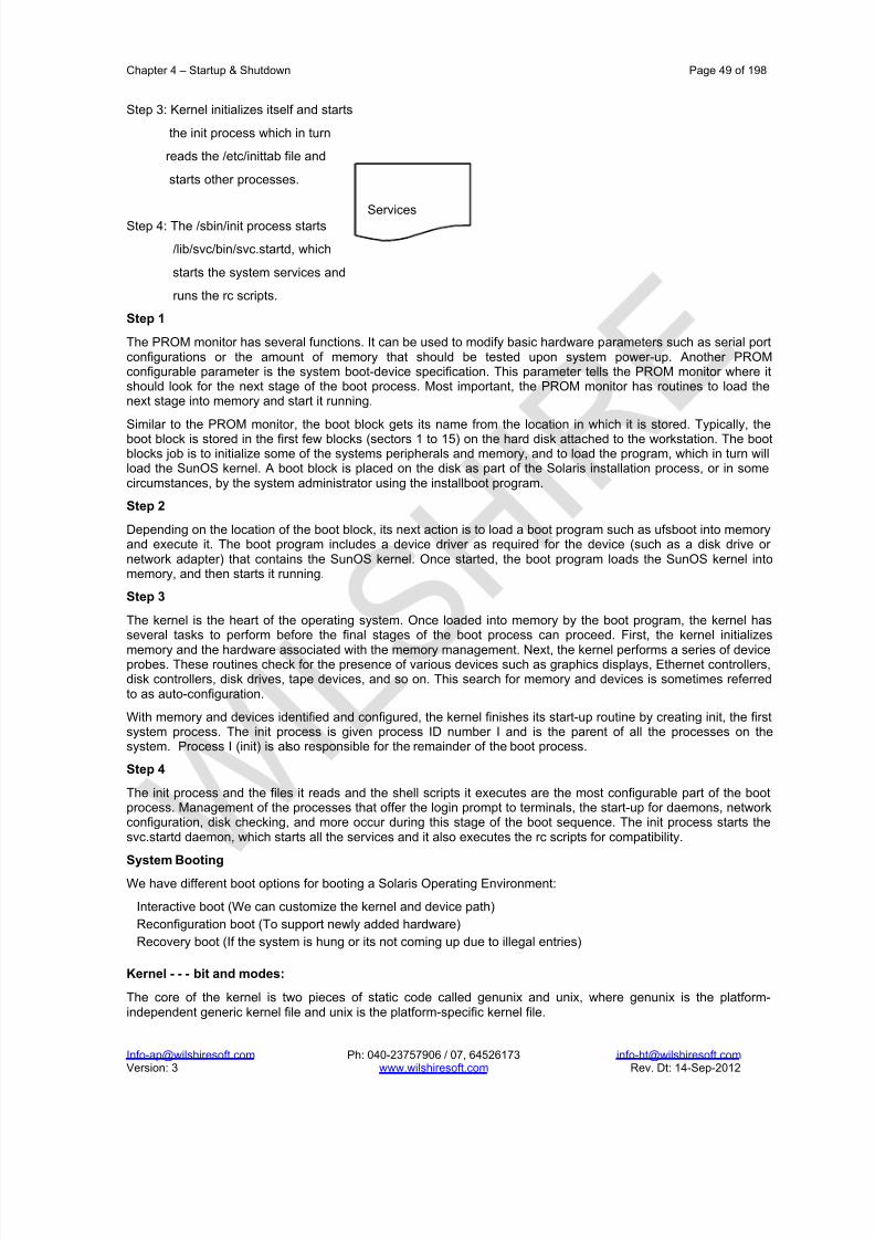
8/22/2019 Solaris%2010%20Handbook.pdf
http://slidepdf.com/reader/full/solaris201020handbookpdf 49/198
Chapter 4 – Startup & Shutdown Page 49 of 198
[email protected] Ph: 040-23757906 / 07, 64526173 [email protected] Version: 3 www.wilshiresoft.com Rev. Dt: 14-Sep-2012
Step 3: Kernel initializes itself and starts
the init process which in turn
reads the /etc/inittab file and
starts other processes.
Step 4: The /sbin/init process starts
/lib/svc/bin/svc.startd, which
starts the system services and
runs the rc scripts.
Step 1
The PROM monitor has several functions. It can be used to modify basic hardware p arameters such as serial portconfigurations or the amount of memory that should be tested upon system power-up. Another PROMconfigurable parameter is the system boot-device specification. This parameter tells the PROM monitor where itshould look for the next stage of the boot process. Most important, the PROM monitor has routines to load thenext stage into memory and start it running.
Similar to the PROM monitor, the boot block gets its name from the location in which it is stored. Typically, theboot block is stored in the first few blocks (sectors 1 to 15) on the hard disk attached to the workstation. The bootblocks job is to initialize some of the systems peripherals and memory, and to load the program, which in turn willload the SunOS kernel. A boot block is placed on the disk as part of the Solaris installation process, or in somecircumstances, by the system administrator using the installboot program.
Step 2
Depending on the location of the boot block, its next action is to load a boot program such as ufsboot into memoryand execute it. The boot program includes a device driver as required for the device (such as a disk drive or network adapter) that contains the SunOS kernel. Once started, the boot program loads the SunOS kernel intomemory, and then starts it running.
Step 3
The kernel is the heart of the operating system. Once loaded into memory by the boot program, the kernel hasseveral tasks to perform before the final stages of the boot process can proceed. First, the kernel initializes
memory and the hardware associated with the memory management. Next, the kernel performs a series of deviceprobes. These routines check for the presence of various devices such as graphics displays, Ethernet controllers,disk controllers, disk drives, tape devices, and so on. This search for memory and devices is sometimes referredto as auto-configuration.
With memory and devices identified and configured, the kernel finishes its start-up routine by creating init, the firstsystem process. The init process is given process ID number I and is the parent of all the processes on thesystem. Process I (init) is also responsible for the remainder of the boot process.
Step 4
The init process and the files it reads and the shell scripts it executes are the most configurable part of the bootprocess. Management of the processes that offer the login prompt to terminals, the start-up for daemons, networkconfiguration, disk checking, and more occur during this stage of the boot sequence. The init process starts thesvc.startd daemon, which starts all the services and it also executes the rc scripts for compatibility.
System Booting
We have different boot options for booting a Solaris Operating Environment:
Interactive boot (We can customize the kernel and device path)
Reconfiguration boot (To support newly added hardware)
Recovery boot (If the system is hung or its not coming up due to illegal entries)
Kernel - - - bit and modes:
The core of the kernel is two pieces of static code called genunix and unix, where genunix is the platform-independent generic kernel file and unix is the platform-specific kernel file.
Services

8/22/2019 Solaris%2010%20Handbook.pdf
http://slidepdf.com/reader/full/solaris201020handbookpdf 50/198
Chapter 4 – Startup & Shutdown Page 50 of 198
[email protected] Ph: 040-23757906 / 07, 64526173 [email protected] Version: 3 www.wilshiresoft.com Rev. Dt: 14-Sep-2012
When ufsboot loads these two files into memory, they are combined to form the running kernel.
On a system running in 32-bit mode, the two-part kernel is located in the directory /platform/‘uname -m‘/kernel.
On a system running in 64-bit mode, the two-part kernel is located in the directory /platform/‘uname -m‘/kernel/sparcv9.
Note – To determine the platform name (for example, the system hardware class), type the uname -m command.For example, when you type this command on an Ultra 10 workstation, the console displays sun4u.
The kernel Initialization Phase
The following describes the kernel initialization phase:
The kernel reads its configuration file, called /etc/system .
The kernel initializes itself and begins loading modules.
Modules can consist of device drivers, binary files to support file systems, and streams, as well as other moduletypes used for specific tasks within the system. The modules that make up the kernel typically reside in thedirectories /kernel and /usr/kernel. Platform-dependent modules reside in the /platform/‘uname -m‘/kernel and/platform/‘uname -i‘/kernel directories. Each subdirectory located under these directories is a collection of similar modules.
x86-boot process

8/22/2019 Solaris%2010%20Handbook.pdf
http://slidepdf.com/reader/full/solaris201020handbookpdf 51/198
Chapter 4 – Startup & Shutdown Page 51 of 198
[email protected] Ph: 040-23757906 / 07, 64526173 [email protected] Version: 3 www.wilshiresoft.com Rev. Dt: 14-Sep-2012
The following describes the types of module subdirectories contained in the /kernel, /usr/kernel, /platform/‘uname-m‘/kernel, or /platform/‘uname -i‘/kernel directories:
drv – Device drivers
exec – Executable file formats
fs – File system types, for example, ufs, nfs, and proc
misc – Miscellaneous modules (virtual swap)
sched – Scheduling classes (process execution scheduling)
strmod – Streams modules (generalized connection between users and device drivers)
sys – System calls (defined interfaces for applications to use)
The /kernel/drv directory contains all of the device drivers that are used for system boot. The /usr/kernel/drvdirectory is used for all other device drivers. Modules are loaded automatically as needed either at boot time or ondemand, if requested by an application. When a module is no longer in use, it might be unloaded on the basis thatthe memory it uses is needed for another task. After the boot process is complete, device drivers are loaded whendevices, such as tape devices, are accessed.
The advantage of this dynamic kernel arrangement is that the overall size of the kernel is smaller, which makesmore efficient use of memory and allows for simpler modification and tuning.
4.2.4. SMF and Booting
SMF provides new methods for booting a system. For instance:
There is a additional system state which is associated with the all milestone. This milestone is different than themultiuser init state because SMF only knows about the services that are defined. If you have added services,such as third party products, they may not be started automatically unless you use the following command:
# boot -m milestone=all
If you boot a system using one of the milestones, it is important to use the –s option as well. If you do not includethe -s, then the system will stay in the milestone state that you booted the system in. The system will not go into
multiuser state automatically by typing Control-D. You can get into the multiuser state by using the followingcommand:
# svcadm milestone -t all
4.2.5. Run Control Scripts
The Solaris software provides a detailed series of run control (rc) scripts to control run-level changes. Each runlevel has an associated rc script that is located in the /sbin directory:
rc0

8/22/2019 Solaris%2010%20Handbook.pdf
http://slidepdf.com/reader/full/solaris201020handbookpdf 52/198
Chapter 4 – Startup & Shutdown Page 52 of 198
[email protected] Ph: 040-23757906 / 07, 64526173 [email protected] Version: 3 www.wilshiresoft.com Rev. Dt: 14-Sep-2012
rc1
rc2
rc3
rc5
rc6
rcS
For each rc script in the /sbin directory, there is a corresponding directory named /etc/rcn.d that contains scripts toperform various actions for that run level. For example, /etc/rc2.d contains files that are used to start and stopprocesses for run level 2. The /etc/rcn.d scripts are always run in ASCII sort order. The scripts have names of theform:
[KS][0-9][0-9]*
Files that begin with K are run to terminate (kill) a system service. Files that begin with S are run to start a systemservice.
Run control scripts are located in the /etc/init.d directory. These files are linked to corresponding run controlscripts in the /etc/rcn.d directories. The actions of each run control script are summarized in the following section.
The /sbin/rc0 Script
The /sbin/rc0 script runs the /etc/rc0.d scripts to perform the following tasks:
Stops system services and daemons Terminates all running processes
Unmounts all file systems
The /sbin/rc1 Script
The /sbin/rc1 script runs the /etc/rc1.d scripts to perform the following tasks:
Stops system services and daemons
Terminates all running user processes
Unmounts all remote file systems
Mounts all local file systems if the previous run level was S
The /sbin/rc2 Script
The /sbin/rc2 script runs the /etc/rc2.d scripts to perform the following tasks, grouped by function:
Starts system accounting and system auditing, if configured
Configures serial device stream
Starts the Solaris PPP server or client daemons (pppoed or pppd), if configured
Configures the boot environment for the Live Upgrade software upon system startup or system shutdown
Checks for the presence of the /etc/.UNCONFIGURE file to see if the system should be reconfigured
Note – Many of the system services and applications that are started at run level 2 depend on what software isinstalled on the system.
The /sbin/rc3 Script
The /sbin/rc3 script runs the /etc/rc3.d scripts to perform the following tasks:
Starts the Apache server daemon (tomcat), if configured
Starts the Samba daemons (smdb and nmdb), if configured
The /sbin/rc5 and /sbin/rc6 ScriptsThe /sbin/rc5 and /sbin/rc6 scripts run the /etc/rc0.d/K* scripts to perform the following tasks:
Kills all active processes
Unmounts the file systems
The /sbin/rcS Script
The /sbin/rcS script runs the /etc/rcS.d scripts to bring the system up to run level S.

8/22/2019 Solaris%2010%20Handbook.pdf
http://slidepdf.com/reader/full/solaris201020handbookpdf 53/198
Chapter 4 – Startup & Shutdown Page 53 of 198
[email protected] Ph: 040-23757906 / 07, 64526173 [email protected] Version: 3 www.wilshiresoft.com Rev. Dt: 14-Sep-2012
4.2.6. System Shutdown
We can shut down the Solaris OE to perform administration tasks or maintenance activities if you are anticipatinga power outage or if you need to move the system to a new location.
The Solaris OE requires a clean and orderly shutdown, which stops processes, writes data in memory to disks,and unmounts file systems. Of course, the type of work you need to do while the system is shut down determineshow the system is shut down and which command you use.
The following describes the different types of system shutdowns.
Shut down the system to single-user mode
Shut down the system to stop the Solaris OE, and display the ok prompt
Shut down the system and turn off power
Shut down the system and automatically reboot to multiuser mode
The commands available to the root user for doing these types of system shutdown procedures include:
/sbin/init (using run levels S, 0, 1, 2, 5, or 6)
/usr/sbin/shutdown (using run levels S, 0, 1, 5, or 6)
/usr/sbin/halt
/usr/sbin/poweroff
/usr/sbin/reboot
The /usr/sbin/shutdown Command
The shutdown command is a script that invokes the init daemon to shut down, power off, or reboot the system. Itexecutes the rc0 kill scripts to shut down processes and applications gracefully. But unlike the init command, theshutdown command does the following:
Notifies all logged-in users that the system is being shut down
Delays the shutdown for 60 seconds by default
Enables you to include an optional descriptive message to inform your users of what will transpire
The command format for the shutdown command is:
shutdown -y -g grace-period -i init-state optional message
The -y option pre-answers the final shutdown confirmation question so that the command runs without your intervention.
The /usr/sbin/halt Command
The halt command performs an immediate system shutdown. It does not execute the rc0 kill scripts. It does notnotify logged-in users, and there is no grace period.
The /usr/sbin/poweroff Command
The poweroff command performs an immediate shutdown. It does not execute the rc0 kill scripts. It does notnotify logged-in users, and there is no grace period.
The /usr/sbin/reboot Command
The reboot command performs an immediate shutdown and reinitialization, bringing the system to run level 3 bydefault. The reboot command differs from the init 6 command because it does not execute the rc0 kill scripts.

8/22/2019 Solaris%2010%20Handbook.pdf
http://slidepdf.com/reader/full/solaris201020handbookpdf 54/198
Chapter 4 – Startup & Shutdown Page 54 of 198
[email protected] Ph: 040-23757906 / 07, 64526173 [email protected] Version: 3 www.wilshiresoft.com Rev. Dt: 14-Sep-2012

8/22/2019 Solaris%2010%20Handbook.pdf
http://slidepdf.com/reader/full/solaris201020handbookpdf 55/198
Chapter 5 – Account Management & Security Page 55 of 198
[email protected] Ph: 040-23757906 / 07, 64526173 [email protected] Version: 3 www.wilshiresoft.com Rev. Dt: 14-Sep-2012
5. Account Management & Security
5.1. What Are User Accounts and Groups?
One basic system administration task is to set up a user account for each user at a site. A typical user accountincludes the information a user needs to log in and use a system, without having the system’s roo t password.
When you set up a user account, you can add the user to predefined groups of users. A typical use of groups is toset up group permissions on a file and directory, which allows access only to users who are part of that group.
For example, you might have a directory containing confidential files that only a few users should be able toaccess. You could set up a group called topsecret that includes the users working on the topsecret project.
And, you could set up the topsecret files with read permission for the topsecret group. That way, only theusers in the topsecret group would be able to read the files. A special type of user account, called a role, is
used to give selected users special privileges.
5.1.1. User Account Components
The following sections describe the specific components of a user account.
User (Login) Names
User names, also called login names, let users access their own systems and remote systems that have theappropriate access privileges. You must choose a user name for each user account that you create.
Consider establishing a standard way of assigning user names so that they are easier for you to track. Also,names should be easy for users to remember. A simple scheme when selecting a user name is to use the firstname initial and first seven letters of the user’s last name. For example, Ziggy Ignatz becomes zignatz. If this
scheme results in duplicate names, you can use the first initial, middle initial, and the first six characters of theuser’s last name. For example, Ziggy Top Ignatz becomes ztignatz. If this scheme still results in duplicate
names, consider using the following scheme to create a user name:
1. The first initial, middle initial, first five characters of the user’s last name
2. The number 1, or 2, or 3, and so on, until you have a unique name
Note – Each new user name must be distinct from any mail aliases that are known to the system or to an NIS or NIS+ domain. Otherwise, mail might be delivered to the alias rather than to the actual user.
User ID Numbers Associated with each user name is a user identification number (UID). The UID number identifies the user nameto any system on which the user attempts to log in. And, the UID number is used by systems to identify theowners of files and directories. If you create user accounts for a single individual on a number of differentsystems, always use the same user name and ID number. In that way, the user can easily move files betweensystems without ownership problems.
UID numbers must be a whole number that is less than or equal to 2147483647. UID numbers are required for both regular user accounts and special system accounts. The following table lists the UID numbers that arereserved for user accounts and system accounts.
Reserved UID Numbers
Do not assign UIDs 0 through 99, which are reserved for system use, to regular user accounts. By definition, rootalways has UID 0, daemon has UID 1, and pseudo-user bin has UID 2. In addition, you should give uucp logins

8/22/2019 Solaris%2010%20Handbook.pdf
http://slidepdf.com/reader/full/solaris201020handbookpdf 56/198
Chapter 5 – Account Management & Security Page 56 of 198
[email protected] Ph: 040-23757906 / 07, 64526173 [email protected] Version: 3 www.wilshiresoft.com Rev. Dt: 14-Sep-2012
and pseudo user logins, such as who, tty, and ttytype, low UIDs so that they fall at the beginning of the passwdfile.
As with user (login) names, you should adopt a scheme to assign unique UID numbers. Some companies assignunique employee numbers. Then, administrators add a number to the employee number to create a unique UIDnumber for each employee.
To minimize security risks, you should avoid reusing the UIDs from deleted accounts. If you must reuse a UID,
“wipe the slate clean” so that the new user is not affected by attributes set for a former user. For ex ample, aformer user might have been denied access to a printer by being included in a printer deny list. However, thatattribute might be inappropriate for the new user.
Using Large User IDs and Group IDs
UIDs and group IDs (GIDs) can be assigned up to the maximum value of a signed integer, or 2147483647.
However, UIDs and GIDs over 60000 do not have full functionality and are incompatible with many Solarisfeatures. So, avoid using UIDs or GIDs over 60000. The following table describes interoperability issues withSolaris products and previous Solaris releases.
Interoperability Issues for UIDs or GIDs Over 60000

8/22/2019 Solaris%2010%20Handbook.pdf
http://slidepdf.com/reader/full/solaris201020handbookpdf 57/198
Chapter 5 – Account Management & Security Page 57 of 198
[email protected] Ph: 040-23757906 / 07, 64526173 [email protected] Version: 3 www.wilshiresoft.com Rev. Dt: 14-Sep-2012
Large UID or GID Limitation Summary
UNIX Groups
A group is a collection of users who can share files and other system resources. For example, users who workingon the same project could be formed into a group. A group is traditionally known as a UNIX group.
Each group must have a name, a group identification (GID) number, and a list of user names that belong to thegroup. A GID number identifies the group internally to the system. The two types of groups that a user can belongto are as follows:
Primary group – Specifies a group that the operating system assigns to files that are created by the user. Eachuser must belong to a primary group.
Secondary groups – Specifies one or more groups to which a user also belongs. Users can belong to up to 15secondary groups.
Sometimes, a user’s secondary group is not important. For example, ownership of files reflect the primary group,not any secondary groups. Other applications, however, might rely on a user’s secondary group memberships.For example, a user has to be a member of the sysadmin group (group 14) to use the Admintool software in
previous Solaris releases. However, it doesn’t matter if group 14 is his or her current primary group.
The groups command lists the groups that a user belongs to. A user can have only one primary group at a time.However, a user can temporarily change the user’s primary group, with the newgrp command, to any other group in which the user is a member.
When adding a user account, you must assign a primary group for a user or accept the default group, staff(group 10). The primary group should already exist. If the primary group does not exist, specify the group by aGID number. User names are not added to primary groups. If user names were added to primary groups, the listmight become too long. Before you can assign users to a new secondary group, you must create the group and
assign it a GID number.
Groups can be local to a system or managed through a name service. To simplify group administration, youshould use a name service such as NIS or a directory service such as LDAP. These services enable you tocentrally manage group memberships.
User Passwords
You can specify a password for a user when you add the user. Or, you can force the user to specify a passwordwhen the user first logs in. User passwords must comply with the following syntax:

8/22/2019 Solaris%2010%20Handbook.pdf
http://slidepdf.com/reader/full/solaris201020handbookpdf 58/198
Chapter 5 – Account Management & Security Page 58 of 198
[email protected] Ph: 040-23757906 / 07, 64526173 [email protected] Version: 3 www.wilshiresoft.com Rev. Dt: 14-Sep-2012
1. Password length must at least match the value identified by the PASSLENGTH variable in the/etc/default/passwd file. By default, PASSLENGTH is set to 6.
2. The first 6 characters of the password must contain at least two alphabetic characters and have at leastone numeric or special character.
3. You can increase the maximum password length to more than eight characters by configuring the/etc/policy.conf file with an algorithm that supports greater than eight characters.
Although user names are publicly known, passwords must be kept secret and known only to users. Each user account should be assigned a password. The password can be a combination of six to eight letters, numbers, or special characters.
To make your computer systems more secure, users should change their passwords periodically. For a high levelof security, you should require users to change their passwords every six weeks. Once every three months isadequate for lower levels of security. System administration logins (such as root and sys) should be changedmonthly, or whenever a person who knows the root password leaves the company or is reassigned.
Many breaches of computer security involve guessing a legitimate user’s password. You should make sure thatusers avoid using proper nouns, names, login names, and other passwords that a person might guess just byknowing something about the user.
Good choices for passwords include the following:
1. Phrases (beammeup).
2. Nonsense words made up of the first letters of every word in a phrase. For example, swotrb for SomeWhere over the RainBow.
3. Words with numbers or symbols substituted for letters. For example, sn00py for snoopy.
Do not use these choices for passwords:
1. Your name (spelled forwards, backwards, or jumbled)
2. Names of family members or pets
3. Car license numbers
4. Telephone numbers
5. Social Security numbers
6. Employee numbers
7. Words related to a hobby or interest
8. Seasonal themes, such as Santa in December
9. Any word in the dictionary
Home Directories
The home directory is the portion of a file system allocated to a user for storing private files. The amount of spaceyou allocate for a home directory depends on the kinds of files the user creates, their size, and the number of filesthat are created.
A home directory can be located either on the user’s local system or on a remote file server. In either case, byconvention the home directory should be created as /export/home/username. For a large site, you should
store home directories on a server. Use a separate file system for each /export/homen directory to facilitatebacking up and restoring home directories. For example, /export/home1, /export/home2.
Regardless of where their home directory is located, users usually access their home directories through a mountpoint named /home/username. When AutoFS is used to mount home directories, you are not permitted to createany directories under the /home mount point on any system. The system recognizes the special status of /home
when AutoFS is active.
To use the home directory anywhere on the network, you should always refer to the home directory as $HOME, notas /export/home/username. The latter is machine-specific. In addition, any symbolic links created in a user’shome directory should use relative paths (for example, ../../../x/y/x) so that the links are valid no matter
where the home directory is mounted.
Name Services
If you are managing user accounts for a large site, you might want to consider using a name or directory servicesuch as LDAP, NIS, or NIS+. A name or directory service enables you to store user account information in a
8/22/2019 Solaris%2010%20Handbook.pdf
http://slidepdf.com/reader/full/solaris201020handbookpdf 59/198
Chapter 5 – Account Management & Security Page 59 of 198
[email protected] Ph: 040-23757906 / 07, 64526173 [email protected] Version: 3 www.wilshiresoft.com Rev. Dt: 14-Sep-2012
centralized manner instead of storing user account informat ion in every system’s /etc files. When you use a
name or directory service for user accounts, users can move from system to system using the same user accountwithout having site-wide user account information duplicated on every system. Using a name or directory servicealso promotes centralized and consistent user account information.
User’s Work Environment
Besides having a home directory to create and store files, users need an environment that gives them access to
the tools and resources they need to do their work. When a user logs in to a system, the user’s work environmentis determined by initialization files. These files are defined by the user’s startup shell, such as the C, Korn, or Bourne shell.
A good strategy for managing the user’s work environment is to provide customized user initialization files, suchas .login, .cshrc, .profile, in the user’s home directory.
Note – Do not use system initialization files, such as /etc/profile or /etc/.login, to manage a user’s work
environment. These files reside locally on systems and are not centrally administered. For example, if AutoFS isused to mount the user’s home directory from any system on the network, you would have to modify the systeminitialization files on each system to ensure a consistent environment whenever a user moved from system tosystem.
Guidelines for Using User Names, User IDs, and Group Ids
User names, UIDs, and GIDs should be unique within your organization, which might span multiple domains.
Keep the following guidelines in mind when creating user or role names, UIDs, and GIDs:
User names – They should contain from two to eight letters and numerals. The first character should be a letter. At least one character should be a lowercase letter.
Note – Even though user names can include a period (.), underscore (_), or hyphen (-), using these characters isnot recommended because they can cause problems with some software products.
System accounts – Do not use any of the user names, UIDs, or GIDs that are contained in the default/etc/passwd and /etc/group files. UIDs and GIDs 0-99 are reserved for system use and should not be
used by anyone. This restriction includes numbers not currently in use.
For example, gdm is the reserved user name and group name for the GNOME Display Manager daemon andshould not be used for another user. For a complete listing of the default /etc/passwd and /etc/groupentries, see Table 4 –6 and Table 4 –9.
The nobody and nobody4 accounts should never be used for running processes. These two accounts arereserved for use by NFS. Use of these accounts for running processes could lead to unexpected security risks.Processes that need to run as a non-root user should use the daemon or noaccess accounts.
System account configuration – The configuration of the default system accounts should never be changed.This includes changing the login shell of a system account that is currently locked. The only exception to this ruleis the setting of a password and password aging parameters for the root account.
5.1.2. Where User Account and Group Information Is Stored
Depending on your site policy, user account and group information can be stored in your local system’s /etcfiles or in a name or directory service as follows:
1. The NIS+ name service information is stored in tables.
2. The NIS name service information is stored in maps.
3. The LDAP directory service information is stored in indexed database files.Note – To avoid confusion, the location of the user account and group information is generically referred to as afile rather than as a database, table, or map. Most user account information is stored in the passwd file.Password information is stored as follows:
1. In the passwd file when you are using NIS or NIS+
2. In the /etc/shadow file when you are using /etc files
3. In the people container when you are using LDAP

8/22/2019 Solaris%2010%20Handbook.pdf
http://slidepdf.com/reader/full/solaris201020handbookpdf 60/198
Chapter 5 – Account Management & Security Page 60 of 198
[email protected] Ph: 040-23757906 / 07, 64526173 [email protected] Version: 3 www.wilshiresoft.com Rev. Dt: 14-Sep-2012
Password aging is available when you are using NIS+ or LDAP, but not NIS. Group information is stored in thegroup file for NIS, NIS+ and files. For LDAP, group information is stored in the group container.
Fields in the passwd File
The fields in the passwd file are separated by colons and contain the following information:
username:password:uid:gid:comment:home-directory:login-shell
For example:
kryten:x:101:100:Kryten Series 4000 Mechanoid:/export/home/kryten:/bin/csh
The following table describes the passwd file fields.
Fields in the passwd File
Default passwd File
The default Solaris passwd file contains entries for standard daemons. Daemons are processes that are usuallystarted at boot time to perform some system-wide task, such as printing, network administration, or portmonitoring.
root:x:0:1:Super-User:/:/sbin/sh
daemon:x:1:1::/:
bin:x:2:2::/usr/bin:
sys:x:3:3::/:
adm:x:4:4:Admin:/var/adm:lp:x:71:8:Line Printer Admin:/usr/spool/lp:
uucp:x:5:5:uucp Admin:/usr/lib/uucp:
nuucp:x:9:9:uucp Admin:/var/spool/uucppublic:/usr/lib/uucp/uucico
smmsp:x:25:25:SendMail Message Submission Program:/:
listen:x:37:4:Network Admin:/usr/net/nls:
gdm:x:50:50:GDM Reserved UID:/:
webservd:x:80:80:WebServer Reserved UID:/:
nobody:x:60001:60001:NFS Anonymous Access User:/:

8/22/2019 Solaris%2010%20Handbook.pdf
http://slidepdf.com/reader/full/solaris201020handbookpdf 61/198
Chapter 5 – Account Management & Security Page 61 of 198
[email protected] Ph: 040-23757906 / 07, 64526173 [email protected] Version: 3 www.wilshiresoft.com Rev. Dt: 14-Sep-2012
noaccess:x:60002:60002:No Access User:/:
nobody4:x:65534:65534:SunOS 4.x NFS Anonymous Access User:/:

8/22/2019 Solaris%2010%20Handbook.pdf
http://slidepdf.com/reader/full/solaris201020handbookpdf 62/198
Chapter 5 – Account Management & Security Page 62 of 198
[email protected] Ph: 040-23757906 / 07, 64526173 [email protected] Version: 3 www.wilshiresoft.com Rev. Dt: 14-Sep-2012
Default passwd File Entries
Fields in the shadow File
The fields in the shadow file are separated by colons and contain the following information:
username:password:lastchg:min:max:warn:inactive:expire
For example:
rimmer:86Kg/MNT/dGu.:8882:0::5:20:8978
The following table describes the shadow file fields.

8/22/2019 Solaris%2010%20Handbook.pdf
http://slidepdf.com/reader/full/solaris201020handbookpdf 63/198
Chapter 5 – Account Management & Security Page 63 of 198
[email protected] Ph: 040-23757906 / 07, 64526173 [email protected] Version: 3 www.wilshiresoft.com Rev. Dt: 14-Sep-2012
Fields in the shadow File
Fields in the group File
The fields in the group file are separated by colons and contain the following information:
group-name:group-password:gid:user-list
For example:
bin::2:root,bin,daemon
The following table describes the group file fields.
Fields in the group File

8/22/2019 Solaris%2010%20Handbook.pdf
http://slidepdf.com/reader/full/solaris201020handbookpdf 64/198
Chapter 5 – Account Management & Security Page 64 of 198
[email protected] Ph: 040-23757906 / 07, 64526173 [email protected] Version: 3 www.wilshiresoft.com Rev. Dt: 14-Sep-2012
Default group file
Default Solaris group file contains following system groups that support some system-wide task, such asprinting, network administration, or electronic mail. Many of these groups having corresponding entries in passwd file.
root::0:other::1:
bin::2:root,daemon
sys::3:root,bin,adm
adm::4:root,daemon
uucp::5:root
mail::6:root
tty::7:root,adm
lp::8:root,adm
nuucp::9:root
staff::10:
daemon::12:root
smmsp::25:
sysadmin::14:
gdm::50:
webservd::80:
nobody::60001:
noaccess::60002:
nogroup::65534:

8/22/2019 Solaris%2010%20Handbook.pdf
http://slidepdf.com/reader/full/solaris201020handbookpdf 65/198
Chapter 5 – Account Management & Security Page 65 of 198
[email protected] Ph: 040-23757906 / 07, 64526173 [email protected] Version: 3 www.wilshiresoft.com Rev. Dt: 14-Sep-2012
Default group File Entries
Tools for Managing User Accounts and Groups
The following table lists the recommended tools for managing users and groups. These tools are included in theSolaris Management Console suite of tools.

8/22/2019 Solaris%2010%20Handbook.pdf
http://slidepdf.com/reader/full/solaris201020handbookpdf 66/198
Chapter 5 – Account Management & Security Page 66 of 198
[email protected] Ph: 040-23757906 / 07, 64526173 [email protected] Version: 3 www.wilshiresoft.com Rev. Dt: 14-Sep-2012
Tools for Managing Users and Groups
Use the Solaris Management Console online help for information on performing these tasks.
For information on the Solaris commands that can be used to manage user accounts and groups, see Table 1 –6.These commands provide the same functionality as the Solaris management tools, including authentication andname service support.
Tasks for Solaris User and Group Management Tools
The Solaris user management tools enable you to manage user accounts and groups on a local system or in aname service environment. This table describes the tasks you can do with the Users tool’s User Accounts feature.
Task Descriptions for User Accounts Tool

8/22/2019 Solaris%2010%20Handbook.pdf
http://slidepdf.com/reader/full/solaris201020handbookpdf 67/198
Chapter 5 – Account Management & Security Page 67 of 198
[email protected] Ph: 040-23757906 / 07, 64526173 [email protected] Version: 3 www.wilshiresoft.com Rev. Dt: 14-Sep-2012
5.1.3. Customizing a User’s Work Environment
Part of setting up a user’s home directory is providing user initialization files for the user’s login shell. A user initialization file is a shell script that sets up a work environment for a user after the user logs in to a system.Basically, you can perform any task in a user initialization file that you can do in a shell script. However, a user initialization file’s primary job is to define the characteristics of a user’s work environment, such as a user’s searchpath, environment variables, and windowing environment. Each login shell has its own user initialization file or
files, which are listed in the following table.
User Initialization Files for Bourne, C, and Korn Shells
The Solaris environment provides default user initialization files for each shell in the /etc/skel directory on
each system, as shown in the following table.
Default User Initialization Files
You can use these files as a starting point and modify them to create a standard set of files that provide the workenvironment common to all users. Or, you can modify these files to provide the working environment for differenttypes of users. Although you cannot create customized user initialization files with the Users tool, you canpopulate a user’s home directory with user initialization files located in a specified “skeleton” directory. You can dothis by creating a user template with the User Templates tool and specifying a skeleton directory from which tocopy user initialization files.
For step-by-step instructions on how to create sets of user initialization files for different types of users, see “Howto Customize User Initialization Files” on page 103. When you use the Users tool to create a new user accountand select the create home directory option, the following files are created, depending on which login shell isselected.
TABLE 4 –19 Files Created by Users Tool When Adding a User
If you use the useradd command to add a new user account and specify the /etc/skel directory by using the
-k and -m options, all three /etc/skel/local* files and the /etc/skel/.profile file are copied into theuser’s home directory. At this point, you need to rename them to whatever is appropriate for the user’s login shell.
Using Site Initialization Files
The user initialization files can be customized by both the administrator and the user. This important feature canbe accomplished with centrally located and globally distributed user initialization files, called site initialization files.Site initialization files enable you to continually introduce new functionality to the user’s work environment, whileenabling the user to customize the user’s initialization file.
When you reference a site initialization file in a user initialization file, all updates to the site initialization file areautomatically reflected when the user logs in to the system or when a user starts a new shell. Site initialization

8/22/2019 Solaris%2010%20Handbook.pdf
http://slidepdf.com/reader/full/solaris201020handbookpdf 68/198
Chapter 5 – Account Management & Security Page 68 of 198
[email protected] Ph: 040-23757906 / 07, 64526173 [email protected] Version: 3 www.wilshiresoft.com Rev. Dt: 14-Sep-2012
files are designed for you to distribute site-wide changes to users’ work environments that you did not anticipatewhen you added the users.
You can customize a site initialization file the same way that you customize a user initialization file. These filestypically reside on a server, or set of servers, and appear as the first statement in a user initialization file. Also,each site initialization file must be the same type of shell script as the user initialization file that references it.
To reference a site initialization file in a C-shell user initialization file, place a line similar to the following at the
beginning of the user initialization file:source /net/machine-name/export/site-files/site-init-file
To reference a site initialization file in a Bourne-shell or Korn-shell user initialization file, place a line similar to thefollowing at the beginning of the user initialization file:
. /net/machine-name/export/site-files/site-init-file
Avoiding Local System References
You should not add specific references to the local system in the user initialization fil e. You want the instructionsin a user initialization file to be valid regardless of which system the user logs into. For example:
1. To make a user’s home directory available anywhe re on the network, always refer to the home directorywith the variable $HOME. For example, use $HOME/bin instead of /export/home/username/bin. The$HOME variable works when the user logs in to another system and the home directories are
automounted.2. To access files on a local disk, use global path names, such as /net/ system-name/directory-name. Any
directory referenced by /net/ system-name can be mounted automatically on any system on which theuser logs in, assuming the system is running AutoFS.
Shell Features
The following table lists basic shell features that each shell provides, which can help you determine what you canand can’t do when creating user initialization files for each shell.
Shell Environment
A shell maintains an environment that includes a set of variables defined by the login program, the systeminitialization file, and the user initialization files. In addition, some variables are defined by default. A shell canhave two types of variables:
Environment variables – Variables that are exported to all processes spawned by the shell. Their settings can beseen with the env command. A subset of environment variables, such as PATH, affects the behavior of the shellitself.
Shell (local) variables – Variables that affect only the current shell. In the C shell, a set of these shell variableshave a special relationship to a corresponding set of environment variables. These shell variables are user, term,home, and path. The value of the environment variable counterpart is initially used to set the shell variable.
In the C shell, you use the lowercase names with the set command to set shell variables. You use uppercase
names with the setenv command to set environment variables. If you set a shell variable, the shell sets thecorresponding environment variable and vice versa. For example, if you update the path shell variable with anew path, the shell also updates the PATH environment variable with the new path.
In the Bourne and Korn shells, you can use the uppercase variable name equal to some value to set both shelland environment variables. You also have to use the export command to activate the variables for any
subsequently executed commands.
For all shells, you generally refer to shell and environment variables by their uppercase names.
In a user initialization file, you can customize a user’s shell environment by changing the values of the predefinedvariables or by specifying additional variables. The following table shows how to set environment variables in auser initialization file.
The PATH Variable
When the user executes a command by using the full path, the shell uses that path to find the command.However, when users specify only a command name, the shell searches the directories for the command in theorder specified by the PATH variable.

8/22/2019 Solaris%2010%20Handbook.pdf
http://slidepdf.com/reader/full/solaris201020handbookpdf 69/198
Chapter 5 – Account Management & Security Page 69 of 198
[email protected] Ph: 040-23757906 / 07, 64526173 [email protected] Version: 3 www.wilshiresoft.com Rev. Dt: 14-Sep-2012
If the command is found in one of the directories, the shell executes the command. A default path is set by thesystem. However, most users modify it to add other command directories. Many user problems related to settingup the environment and accessing the correct version of a command or a tool can be traced to incorrectly definedpaths.
Setting Path Guidelines
Here are some guidelines for setting up efficient PATH variables:
1. If security is not a concern, put the current working directory (.) first in the path. However, including thecurrent working directory in the path poses a security risk that you might want to avoid, especially for superuser.
2. Keep the search path as short as possible. The shell searches each directory in the path. If a command isnot found, long searches can slow down system performance.
3. The search path is read from left to right, so you should put directories for commonly used commands atthe beginning of the path.
4. Make sure that directories are not duplicated in the path.
5. Avoid searching large directories, if possible. Put large directories at the end of the path.
6. Put local directories before NFS mounted directories to lessen the chance of “hanging” when the NFSserver does not respond. This strategy also reduces unnecessary network traffic.
Examples—Setting a User’s Default Path
The following examples show how to set a user’s default path to include the home directory and other NFSmounted directories. The current working directory is specified first in the path. In a C-shell user initialization file,you would add the following:
set path=(. /usr/bin $HOME/bin /net/glrr/files1/bin)
In a Bourne-shell or Korn-shell user initialization file, you would add the following:
PATH=.:/usr/bin:/$HOME/bin:/net/glrr/files1/bin
export PATH
Locale Variables
The LANG and LC environment variables specify the locale-specific conversions and conventions for the shell.
These conversions and conventions include time zones, collation orders, and formats of dates, time, currency,and numbers. In addition, you can use the stty command in a user initialization file to indicate whether the
terminal session will support multibyte characters.The LANG variable sets all possible conversions and conventions for the given locale. You can set variousaspects of localization separately through these LC variables:
LC_COLLATE, LC_CTYPE, LC_MESSAGES, LC_NUMERIC, LC_MONETARY, and LC_TIME.
The following table describes some of the values for the LANG and LC environment variables.
Default File Permissions (umask)
When you create a file or directory, the default file permissions assigned to the file or directory are controlled bythe user mask. The user mask is set by the umask command in a user initialization file. You can display thecurrent value of the user mask by typing umask and pressing Return.
The user mask contains the following octal values:
1. The first digit sets permissions for the user
2. The second digit sets permissions for group
3. The third digit sets permissions for other, also referred to as world
Note that if the first digit is zero, it is not displayed. For example, if the user mask is set to 022, 22 is displayed.
To determine the umask value you want to set, subtract the value of the permissions you want from 666 (for afile) or 777 (for a directory). The remainder is the value to use with the umask command. For example, suppose
you want to change the default mode for files to 644 ( rw-r--r--). The difference between 666 and 644 is 022,which is the value you would use as an argument to the umask command.

8/22/2019 Solaris%2010%20Handbook.pdf
http://slidepdf.com/reader/full/solaris201020handbookpdf 70/198
Chapter 5 – Account Management & Security Page 70 of 198
[email protected] Ph: 040-23757906 / 07, 64526173 [email protected] Version: 3 www.wilshiresoft.com Rev. Dt: 14-Sep-2012
You can also determine the umask value you want to set by using the following table. This table shows the file
and directory permissions that are created for each of the octal values of umask.
Examples of User and Site Initialization Files
The following sections provide examples of user and site initialization files that you can use to start customizingyour own initialization files. These examples use system names and paths that you need to change for your
particular site.
The .profile File
(Line 1) PATH=$PATH:$HOME/bin:/usr/local/bin:/usr/ccs/bin:.
(Line 2) MAIL=/var/mail/$LOGNAME
(Line 3) NNTPSERVER=server1
(Line 4) MANPATH=/usr/share/man:/usr/local/man
(Line 5) PRINTER=printer1
(Line 6) umask 022
(Line 7) export PATH MAIL NNTPSERVER MANPATH PRINTER
1. Defines the user’s shell search path
2. Defines the path to the user’s mail file
3. Defines the user’s Usenet news server
4. Defines the user’s search path for man pages 5. Defines the user’s default printer
6. Sets the user’s default file creation permissions
7. Sets the listed environment variables
The .cshrc File
(Line 1) set path=($PATH $HOME/bin /usr/local/bin /usr/ccs/bin)
(Line 2) setenv MAIL /var/mail/$LOGNAME
(Line 3) setenv NNTPSERVER server1
(Line 4) setenv PRINTER printer1
(Line 5) alias h history
(Line 6) umask 022
(Line 7) source /net/server2/site-init-files/site.login
1. Defines the user’s shell search path.
2. Defines the path to the user’s mail file.
3. Defines the user’s Usenet news server.
4. Defines the user’s default printer.
5. Creates an alias for the history command. The user needs to type only h to run the historycommand.
6. Sets the user’s default file creation permissions.
7. Sources the site initialization file.
Site Initialization File
The following shows an example site initialization file in which a user can choose a particular version of anapplication.
# @(#)site.login main:
echo "Application Environment Selection"
echo ""
echo "1. Application, Version 1"
echo "2. Application, Version 2"
echo ""
echo -n "Type 1 or 2 and press Return to set your
application environment: "

8/22/2019 Solaris%2010%20Handbook.pdf
http://slidepdf.com/reader/full/solaris201020handbookpdf 71/198
Chapter 5 – Account Management & Security Page 71 of 198
[email protected] Ph: 040-23757906 / 07, 64526173 [email protected] Version: 3 www.wilshiresoft.com Rev. Dt: 14-Sep-2012
set choice = $<
if ( $choice !~ [1-2] ) then
goto main
endif
switch ($choice)
case "1":
setenv APPHOME /opt/app-v.1 breaksw
case "2":
setenv APPHOME /opt/app-v.2
endsw
This site initialization file could be referenced in a user’s .cshrc file (C shell users only) with the following line:
source /net/server2/site-init-files/site.login
In this line, the site initialization file is named site.login and is located on a server named server2. This linealso assumes that the automounter is running on the user’s system.
5.1.4. Quotas
What Are Quotas?Quotas enable system administrators to control the size of UFS file systems. Quotas limit the amount of diskspace and the number of inodes, which roughly corresponds to the number of files that individual users canacquire. For this reason, quotas are especially useful on the file systems where user home directories reside.
Using Quotas
Once quotas are in place, they can be changed to adjust the amount of disk space or the number of inodes thatusers can consume. Additionally, quotas can be added or removed, as system needs change.
In addition, quota status can be monitored. Quota commands enable administrators to display information aboutquotas on a file system, or search for users who have exceeded their quotas.
Setting Soft Limits and Hard Limits for Quotas
You can set both soft limits and hard limits. The system does not allow a user to exceed his or her hard limit.
However, a system administrator might set a soft limit, which the user can temporarily exceed. The soft limit mustbe less than the hard limit. Once the user exceeds the soft limit, a quota timer begins. While the quota timer isticking, the user is allowed to operate above the soft limit but cannot exceed the hard limit. Once the user goesbelow the soft limit, the timer is reset. However, if the user’s usage remains above the soft limit when the timer expires, the soft limit is enforced as a hard limit. By default, the soft limit timer is set to seven days.
The timeleft field in the repquota and quota commands shows the value of the timer.
For example, let’s say a user has a soft limit of 10,000 blocks and a hard limit of 12,000 blocks. If the user’s blockusage exceeds 10,000 blocks and the seven-day timer is also exceeded, the user cannot allocate more diskblocks on that file system until his or her usage drops below the soft limit.
The Difference between Disk Block and File Limits
A file system provides two resources to the user, blocks for data and inodes for files. Each file consumes oneinode. File data is stored in data blocks. Data blocks are usually made up of 1Kbyte blocks.
5.2. System Security
5.2.1. Monitoring System Access
All systems should be monitored routinely for unauthorized user access. You can determine who is or who hasbeen logged into the system by executing commands and examining log files.
Displaying Users on the Local System

8/22/2019 Solaris%2010%20Handbook.pdf
http://slidepdf.com/reader/full/solaris201020handbookpdf 72/198
Chapter 5 – Account Management & Security Page 72 of 198
[email protected] Ph: 040-23757906 / 07, 64526173 [email protected] Version: 3 www.wilshiresoft.com Rev. Dt: 14-Sep-2012
The who command displays a list of users currently logged in to the local system. It displays each user’s login
name, the login device (TTY port), the login date and time. The command reads the binary file /var/adm/utmpx to obtain this information and information about where the users logged in from.
If a user is logged in remotely, the who command displays the remote host name, or Internet Protocol (IP)
address in the last column of the output.
# who
root console Oct 29 16:09 (:0)root pts/4 Oct 29 16:09 (:0.0)
root pts/5 Oct 29 16:10 (192.168.0.234)
alice pts/7 Oct 29 16:48 (192.168.0.234)
The second field displayed by the who command defines the user’s login device, which is one of the following:
console – The device used to display system boot and error messages
pts – The pseudo device that represents a login or window session without a physical device
term – The device physically connected to a serial port, such as a terminal or a modem
Displaying Users on Remote Systems
The rusers command produces output similar to that of the who command, but it displays a list of the users logged
in on local and remote hosts. The list displays the user’s name and the host’s name in the order in which theresponses are received from the hosts.
A remote host responds only to the rusers command if its rpc.rusersd daemon is enabled. The rpc.rusersd daemon is the network server daemon that returns the list of users on the remote hosts.
Note – The full path to this network server daemon is /usr/lib/netsvc/rusers/rpc.rusersd .
Displaying User Information
To display detailed information about user activity that is either local or remote, use the finger command.
The finger command displays:
1. The user’s login name
2. The home directory path
3. The login time
4. The login device name5. The data contained in the comment field of the /etc/passwd file (usually the user’s full name)
6. The login shell
7. The name of the host, if the user is logged in remotely, and any idle time
Note – You get a response from the finger command only if the in.fingerd daemon is enabled.
Displaying a Record of Login Activity
Use the last command to display a record of all logins and logouts with the most recent activity at the top of theoutput. The last command reads the binary file /var/adm/wtmpx , which records all logins, logouts, and reboots.
Each entry includes the user name, the login device, the host that the user is logged in from, the date and timethat the user logged in, the time of logout, and the total login time in hours and minutes, including entries for system reboot times.
The output of the last command can be extremely long. Therefore, you might want to use it with the -n number option to specify the number of lines to display.
Recording Failed Login Attempts
When a user logs in to a system either locally or remotely, the login program consults the /etc/ passwd and the
/etc/shadow files to authenticate the user. It verifies the user name and password entered.
If the user provides a login name that is in the /etc/passwd file and the correct password for that login name,the login program grants access to the system.

8/22/2019 Solaris%2010%20Handbook.pdf
http://slidepdf.com/reader/full/solaris201020handbookpdf 73/198
Chapter 5 – Account Management & Security Page 73 of 198
[email protected] Ph: 040-23757906 / 07, 64526173 [email protected] Version: 3 www.wilshiresoft.com Rev. Dt: 14-Sep-2012
If the login name is not in the /etc/passwd file or the password is not correct for the login name, the login
program denies access to the system. You can log failed command-line login attempts in the/var/adm/loginlog file. This is a useful tool if you want to determine if attempts are being made to break into
a system.
By default, the loginlog file does not exist. To enable logging, you should create this file with read and writepermissions for the root user only, and it should belong to the sys group.
# touch /var/adm/loginlog# chown root:sys /var/adm/loginlog
# chmod 600 /var/adm/loginlog
All failed command-line login activity is written to this file automatically after five consecutive failed attempts.
The loginlog file contains one entry for each of the failed attempts. Each entry contains the user’s login name,login device (TTY port), and time of the failed attempt. If there are fewer than five consecutive failed attempts, noactivity is logged to this file.
5.2.2. Switching Users on a System
As the system administrator, you should log in to a system as a regular user, and then switch to the root accountonly to perform administrative tasks.
You should avoid logging in directly as the root user. This precaution helps protect the system from unauthorizedaccess, because it reduces the likelihood that the system will be left unattended with the root user logged in. Also,critical mistakes are less likely to occur if you perform routine work as a regular system user.
Introducing the su Command
su command is used to gain root privileges.
The su command is an application, which provides a means of gaining the authority of another user by supplyingthe user’s password when prompted. If the password is correct, the su command creates a new shell process, as
specified in the shell field of that user account’s /etc/passwd file entry.
The su - (dash) option specifies a complete login by reading all of the user’s shell initialization files. The - (dash)
option changes your work environment to what would be expected if you had logged in directly as that specifieduser. It also changes the user’s home directory.
Displaying the Effective User ID
When you run the su command, the user ID and the user group ID (GID) change to that of the user to which youhave switched, becoming the EUID and effective group ID (EGID), respectively.
Access to files and directories is determined by the value of the EUID and EGID for the effective user, rather thanby the UID and GID numbers of the original user who logged in to the system.
The whoami command displays the login name of the EUID.
Note – The whoami command resides in the /usr/ucb directory.
Displaying the Real User ID
To determine the login name of the original user use the who command with the am i option.
To use the who am i command, at the shell prompt, type the su command and the login name of the user
account to which you want to switch, and press Return. Type the password for the user account, and press
Return. Invoked without a user name, the su command offers access to root account. Because of the authoritygiven to the root user, the su command maintains its own log file, /var/adm/sulog
How to monitor who is using the su Command
The sulog file lists every use of the su command, not only the su attempts that are used to switch from user tosuperuser.
The entries of /var/adm/sulog display the following information:
1. The date and time that the command was entered.

8/22/2019 Solaris%2010%20Handbook.pdf
http://slidepdf.com/reader/full/solaris201020handbookpdf 74/198
Chapter 5 – Account Management & Security Page 74 of 198
[email protected] Ph: 040-23757906 / 07, 64526173 [email protected] Version: 3 www.wilshiresoft.com Rev. Dt: 14-Sep-2012
2. If the attempt was successful. A plus sign (+) indicates a successful attempt. A minus sign (-) indicates anunsuccessful attempt.
3. The port from which the command was issued.
4. The name of the user and the name of the switched identity.
The su logging in this file is enabled by default through the following entry in the /etc/default/su file:
SULOG=/var/adm/sulog
5.2.3. Controlling System Access
System security ensures that the system’s resources are used properly. Access controls can restrict who ispermitted access to resources on the system. The Solaris OS features for system security and access controlinclude the following:
Login administration tools – Commands for monitoring and controlling a user’s ability to log in.
Hardware access – Commands for limiting access to the PROM, and for restricting who can boot the system.
Resource access – Tools and strategies for maximizing the appropriate use of machine resources whileminimizing the misuse of those resources.
Role-based access control (RBAC) – Architecture for creating special, restricted user accounts that arepermitted to perform specific administrative tasks.
Privileges – Discrete rights on processes to perform operations. These process rights are enforced in the kernel.
Device management – Device policy additionally protects devices that are already protected by UNIXpermissions. Device allocation controls access to peripheral devices, such as a microphone or CD-ROM drive.Upon deallocation, device-clean scripts can then erase any data from the device.
Basic Audit Reporting Tool (BART) – A snapshot, called a manifest, of the file attributes of files on a system. Bycomparing the manifests across systems or on one system over time, changes to files can be monitored to reducesecurity risks.
File permissions – Attributes of a file or directory. Permissions restrict the users and groups that are permitted toread, write, or execute a file, or search a directory.
Security enhancement scripts – Through the use of scripts, many system files and parameters can be adjustedto reduce security risks.
Using UNIX Permissions to Protect FilesFiles can be secured through UNIX file permissions and through ACLs. Files with sticky bits, and files that areexecutable, require special security measures.
You can protect the files in a directory and its subdirectories by setting restrictive file permissions on thatdirectory. Note, however, that superuser has access to all files and directories on the system.
Special File Permissions (setuid, setgid and Sticky Bit)
Three special types of permissions are available for executable files and public directories: setuid, setgid, andsticky bit. When these permissions are set, any user who runs that executable file assumes the ID of the owner (or group) of the executable file.
You should monitor your system for any unauthorized use of the setuid permission and the setgid permission togain superuser capabilities. A suspicious permission grants ownership of an administrative program to a user rather than to root or bin.
setuid Permission
When setuid permission is set on an executable file, a process that runs this file is granted access on the basis of the owner of the file. The access is not based on the user who is running the executable file. This specialpermission allows a user to access files and directories that are normally available only to the owner.
For example, the setuid permission on the passwd command makes it possible for users to change passwords. Apasswd command with setuid permission would resemble the following:
-r-sr-sr-x 1 root sys 27220 Jan 23 2005 /usr/bin/passwd

8/22/2019 Solaris%2010%20Handbook.pdf
http://slidepdf.com/reader/full/solaris201020handbookpdf 75/198
Chapter 5 – Account Management & Security Page 75 of 198
[email protected] Ph: 040-23757906 / 07, 64526173 [email protected] Version: 3 www.wilshiresoft.com Rev. Dt: 14-Sep-2012
This special permission presents a security risk. Some determined users can find a way to maintain thepermissions that are granted to them by the setuid process even after the process has finished executing.
setgid Permission
The setgid permission is similar to the setuid permission. The process’s effective group ID (GID) is ch anged to thegroup that owns the file, and a user is granted access based on the permissions that are granted to that group.The /usr/bin/mail command has setgid permissions:
-r-x--s--x 1 root mail 67900 Jan 23 2005 /usr/bin/mail
When the setgid permission is applied to a directory, files that were created in this directory belong to the group towhich the directory belongs. The files do not belong to the group to which the creating process belongs. Any user who has write and execute permissions in the directory can create a file there. However, the file belongs to thegroup that owns the directory, not to the group that the user belongs to.
Sticky Bit
The sticky bit is a permission bit that protects the files within a directory. If the directory has the sticky bit set, a filecan be deleted only by the file owner, the directory owner, or by a privileged user. The root user and the Primary Administrator role are examples of privileged users. The sticky bit prevents a user from deleting other user s’ filesfrom public directories such as /tmp:
drwxrwxrwt 7 root sys 528 Oct 29 14:49 /tmp
Be sure to set the sticky bit manually when you set up a public directory on a TMPFS file system.File Permission Modes
The chmod command enables you to change the permissions on a file. You must be superuser or the owner of afile or directory to change its permissions. You can use the chmod command to set permissions in either of twomodes:
Absolute Mode – Use numbers to represent file permissions. When you change permissions by using theabsolute mode, you represent permissions for each triplet by an octal mode number. Absolute mode is themethod most commonly used to set permissions.
Symbolic Mode – Use combinations of letters and symbols to add permissions or remove permissions.
You must use symbolic mode to set or remove setuid permissions on a directory. In absolute mode, you setspecial permissions by adding a new octal value to the left of the permission triplet. The following table lists theoctal values for setting special permissions on a file.
The following table lists the octal values for setting file permissions in absolute mode.
who Specifies whose permissions are to be changed.
operator Specifies the operation to be performed.
permissions Specifies what permissions are to be changed.
Special File Permissions in Absolute Mode
Using Access Control Lists to Protect Files
Traditional UNIX file protection provides read, write, and execute permissions for the three user classes: fileowner, file group, and other. An access control list (ACL) provides better file security by enabling you to do thefollowing:
Define file permissions for the file owner, the group, other, specific users and groups
Define default permissions for each of the preceding categories

8/22/2019 Solaris%2010%20Handbook.pdf
http://slidepdf.com/reader/full/solaris201020handbookpdf 76/198
Chapter 5 – Account Management & Security Page 76 of 198
[email protected] Ph: 040-23757906 / 07, 64526173 [email protected] Version: 3 www.wilshiresoft.com Rev. Dt: 14-Sep-2012
For example, if you want everyone in a group to be able to read a file, you can simply grant group readpermissions on that file. Now, assume that you want only one person in the group to be able to write to that file.Standard UNIX does not provide that level of file security. However, an ACL provides this level of file security.
ACL entries define an ACL on a file. The entries are set through the setfacl command. ACL entries consist of thefollowing fields separated by colons:
entry-type:[uid|gid]:perms
entry-type Is the type of ACL entry on which to set file permissions. For example, entry-type can be user (theowner of a file) or mask (the ACL mask).
uid Is the user name or user ID (UID).
gid Is the group name or group ID (GID).
perms Represents the permissions that are set on entry-type. perms can be indicated by the symbolic charactersrwx or an octal number. These are the same numbers that are used with the chmod command.
Caution – UFS file system attributes such as ACLs are supported in UFS file systems only. Thus, if you restore or copy files with ACL entries into the /tmp directory, which is usually mounted as a TMPFS file system, the ACLentries will be lost. Use the /var/tmp directory for temporary storage of UFS files.
ACL Entries for Files
The following table lists the valid ACL entries that you might use when setting ACLs on files. The first three ACL
entries provide the basic UNIX file protection.
ACL Entries for Directories
We can set default ACL entries on a directory. Files or directories created in a directory that has default ACLentries will have the same ACL entries as the default ACL entries.
When you set default ACL entries for specific users and groups on a directory for the first time, you must also setdefault ACL entries for the file owner, file group, others, and the ACL mask. These entries are required. They arethe first four default ACL entries in the following table.
Default ACL Entry Description
d[efault]:u[ser]::perms Default file owner permissions.
d[efault]:g[roup]::perms Default file group permissions.
d[efault]:o[ther]:perms Default permissions for users other than the file owner or members of the file group.
d[efault]:m[ask]:perms Default ACL mask.
d[efault]:u[ser]:uid:perms Default permissions for a specific user. For uid, you can specify either a user nameor a
numeric UID.
d[efault]:g[roup]:gid:perms Default permissions for a specific group. For gid, you can specify either a groupname
or a numeric GID.
Commands for Administering ACLs
The following commands administer ACLs on files or directories.
setfacl command Sets, adds, modifies, and deletes ACL entries.
getfacl command Displays ACL entries.
5.2.4. ftp, rlogin, ssh
File Transfer Protocol (FTP) Access
The Solaris OE provides an American Standard Code for Information Interchange (ASCII) file named/etc/ftpd/ftpusers. The /etc/ftpd/ftpusers file lists the names of users who are prohibited from connecting to thesystem through the FTP protocol. Each line entry in this file contains a login name for a restricted user.

8/22/2019 Solaris%2010%20Handbook.pdf
http://slidepdf.com/reader/full/solaris201020handbookpdf 77/198
Chapter 5 – Account Management & Security Page 77 of 198
[email protected] Ph: 040-23757906 / 07, 64526173 [email protected] Version: 3 www.wilshiresoft.com Rev. Dt: 14-Sep-2012
The FTP server daemon in.ftpd reads the /etc/ftpd/ftpusers file when an FTP session is invoked. If the login nameof the user matches one of the listed entries, it rejects the login session and sends the Login failed error message.
The root entry is included in the ftpusers file as a security measure. The default security policy is to disallowremote logins for the root user. The policy is also followed for the default value set as the CONSOLE entry in the/etc/default/login file.
The /etc/hosts.equiv and $HOME/.rhosts Files
Typically, when a remote user requests login access to a local host, the first file read by the local host is its/etc/passwd file. An entry for that particular user in this file enables that user to log in to the local host from aremote system. If a password is associated with that account, then the remote user is required to supply thispassword at log in to gain system access. If there is no entry in the local host’s /etc/passwd file for the remoteuser, access is denied.
The /etc/hosts.equiv and $HOME/.rhosts files bypass this standard password-based authentication to determine if a remote user is allowed to access the local host, with the identity of a local user. These files provide a remoteauthentication procedure to make that determination.
This procedure first checks the /etc/hosts.equiv file and then checks the $HOME/.rhosts file in the home directoryof the local user who is requesting access. The information contained in these two files (if they exist) determines if remote access is granted or denied. The information in the /etc/hosts.equiv file applies to the entire system, whileindividual users can maintain their own $HOME/.rhosts files in their home directories.
Entries in the /etc/hosts.equiv and $HOME/.rhosts Files
While the /etc/hosts.equiv and $HOME/.rhosts files have the same format, the same entries in each file havedifferent effects. Both files are formatted as a list of one-line entries, which can contain the following types of entries:
hostname
hostname username
+
The host names in the /etc/hosts.equiv and $HOME/.rhosts files must be the official name of the host, not one of its alias names.
If the local host’s /etc/hosts.equiv file contains the host name of a remote host, then all regular users of thatremote host are trusted and do not need to supply a password to log in to the local host. This is provided so thateach remote user is known to the local host by having an entry in the local /etc/passwd file; otherwise, access isdenied.
This funtionality is particularly useful for sites where regular users commonly have accounts on many differentsystems, eliminating the security risk of sending ASCII passwords over the network.
The /etc/hosts.equiv file does not exist by default. It must be created if trusted remote user access is required onthe local host.
The $HOME/.rhosts File Rules
While the /etc/hosts.equiv file applies system-wide access for nonroot users, the .rhosts file applies to a specificuser.
All users, including the root user, can create and maintain their own .rhosts files in their home directories. For example, if you run an rlogin process from a remote host to gain root access to a local host, the /.rhosts file ischecked in the root home directory on the local host.
If the remote host name is listed in this file, it is a trusted host, and, in this case, root access is granted on the
local host. The CONSOLE variable in the /etc/default/login file must be commented out for remote root logins. The$HOME/.rhosts file does not exist by default. You must create it in the user’s home directory.
SSH (Solaris Secure Shell) – It is a secure remote login and transfer protocol that encryptscommunications over an insecure network.
In Solaris Secure Shell, authentication is provided by the use of passwords, public keys, or both. All networktraffic is encrypted. Thus, Solaris Secure Shell prevents a would-be intruder from being able to read anintercepted communication. Solaris Secure Shell also prevents an adversary from spoofing the system.
With Solaris Secure Shell, you can perform these actions:

8/22/2019 Solaris%2010%20Handbook.pdf
http://slidepdf.com/reader/full/solaris201020handbookpdf 78/198
Chapter 5 – Account Management & Security Page 78 of 198
[email protected] Ph: 040-23757906 / 07, 64526173 [email protected] Version: 3 www.wilshiresoft.com Rev. Dt: 14-Sep-2012
Log in to another host securely over an unsecured network.
Copy files securely between the two hosts.
Run commands securely on the remote host.
A Typical Solaris Secure Shell Session
The Solaris Secure Shell daemon (sshd) is normally started at boot time when network services are started. Thedaemon listens for connections from clients. A Solaris Secure Shell session begins when the user runs an ssh,
scp, or sftp command. A new sshd daemon is forked for each incoming connection. The forked daemons handlekey exchange, encryption, authentication, command execution, and data exchange with the client. These sessioncharacteristics are determined by client-side configuration files and server-side configuration files. Command-linearguments can override the settings in the configuration files. The client and server must authenticate themselvesto each other. After successful authentication, the user can execute commands remotely and copy data betweenhosts.

8/22/2019 Solaris%2010%20Handbook.pdf
http://slidepdf.com/reader/full/solaris201020handbookpdf 79/198
Chapter 6 – Printers Page 79 of 198
[email protected] Ph: 040-23757906 / 07, 64526173 [email protected] Version: 3 www.wilshiresoft.com Rev. Dt: 14-Sep-2012
6. PrintersThe Solaris printing service provides a complete network-printing environment. This environment allows sharingof printers across machines, management of special printing situations such as forms, and filtering output tomatch special printer types such as those that use the popular PostScript page description language. This releasealso supports IPP, and also expanded printer support (through the use of additional transformation software,raster image processor (RIP), and PostScript Printer Description (PPD) files, you can print to a wider range of
printers.
6.1. Printing Terminology
Printing services on Solaris use a set of special commands, daemons, filters, and directories. Files are not directlysent to the printer, but are spooled and then printed, freeing whatever application submitted the print request tomove on to other tasks. The term spooling refers to the temporary storage of a file for later use. It comes from theearly history of computing when files to be printed were saved temporarily on spools of magnetic tape.
Here spooling is defined as the process of placing a file in a special directory while it waits to be printed. Spoolingputs the SunOS multi-tasking capability to good use by allowing printing to occur at the same time as other activities. An example of a printing service is illustrated
Print File
Spool directory
lpsched, output filters, etc.
Printer
Print Client Print Server
The actual work of printing is executed by a printing daemon. Daemon is the nickname given to all processesrunning on a UNIX system. The main printing daemon is lpsched.
Most output bound for a printer will require filtering before it is printed. The term filter is used to describe aprogram that transforms the content of one file into another format as the file passes through the program. For instance, when an ASCII file is sent to the printer that accepts the PostScript page description language, the printservice first runs the file through a filter to transform the file from ASCII into PostScript.
The resulting PostScript file contains complete instructions in a form the printer can use to print the page, and issomewhat larger than the original file due to the addition of this information. After filtering, the PostScript file issent to the printer which reads a description of the pages to be printed and prints them.
Printing can be set up as a network-wide service. There are three varieties of network printing.
1. Machines with directly connected printers that accept print requests from other machines are called print servers.
2. Machines that submit print requests over the network to other machines are called print-clients. Amachine can be both a print server and a print client.
3. Printers directly attached to the workstation are known as local printers, whereas printers attached toother workstations reached via the network are known as remote printers.

8/22/2019 Solaris%2010%20Handbook.pdf
http://slidepdf.com/reader/full/solaris201020handbookpdf 80/198
Chapter 6 – Printers Page 80 of 198
[email protected] Ph: 040-23757906 / 07, 64526173 [email protected] Version: 3 www.wilshiresoft.com Rev. Dt: 14-Sep-2012
Finally, it is increasingly common for printers to be directly attached to the network. These network printers caneither be served from a print server or act as their own print server, depending on the facilities provided in theprinter by the manufacturer.
6.2. Printing in the Solaris Operating System
The Solaris printing software provides an environment for setting up and managing client access to printers on a
network. The Solaris printing software contains these tools:
1. Solaris Print Manager – A graphical user interface (GUI) that provides the ability to manage printingconfiguration on a local system or in a name service.
2. The LP print service commands – A command-line interface (CLI) that is used to set up and manageprinters on a local system or in a name service. These commands also provide functionality that extendbeyond the other print management tools.
Even if you do use Solaris Print Manager to set up printing, you will have to use some of the lp print servicecommands to completely manage printing on the Solaris Operating System.
Solaris Print Manager
Solaris Print Manager is a Java technology-based GUI that enables you to manage local and remote printer configuration. This tool can be used in the following name service environments: LDAP, NIS, NIS+, and files.Solaris Printer Manager centralizes printer information when used in conjunction with a name service. Using a
name service for storing printer configuration information is desirable because a name service makes printer information available to all systems on the network. This method provides easier printing administration.
Solaris Print Manager recognizes existing printer information on the printer servers, print clients, and in the nameservice databases. No conversion tasks are required to use Solaris Print Manager as long as the print clients arerunning either the Solaris 2.6, 7, 8, 9, or 10 releases.
The Solaris Print Manager package is SUNWppm.
Printing Support in the Name Service Switch
The printers database in /etc/nsswitch.conf, the name service switch file, provides centralized printer configurationinformation to print clients on the network. By including the printers database and corresponding sources of information in the name service switch file, print clients automatically have access to printer configurationinformation without having to add it to their own systems. The default printers entry in the /etc/nsswitch.conf filefor files, LDAP, NIS, and NIS+ environments are described in the following table. The nisplus keyword representsthe printers.org_dir table.
For example, if your name service is NIS, printer configuration information on print clients is searched for in thefollowing sources in this order:
user – Represents the user’s $HOME/.printers file files – Represents the /etc/printers.conf file
nis – Represents the printers.conf.byname table
Most printing configuration tasks can be accomplished with Solaris Print Manager. However, if you need to writeinterface scripts or add your own filters, you need to use the LP print service commands. These commandsunderlie Solaris Print Manager.
Managing Network Printers

8/22/2019 Solaris%2010%20Handbook.pdf
http://slidepdf.com/reader/full/solaris201020handbookpdf 81/198
Chapter 6 – Printers Page 81 of 198
[email protected] Ph: 040-23757906 / 07, 64526173 [email protected] Version: 3 www.wilshiresoft.com Rev. Dt: 14-Sep-2012
A network printer is a hardware device that is connected directly to the network. A network printer transfers datadirectly over the network to the output device. The printer or network connection hardware has its own systemname and IP address. Network printers often have software support provided by the printer vendor. If your printer has printer vendor-supplied software, then use the printer vendor software. If the network printer vendor does notprovide software support, Sun supplied software is available. This software provides generic support for network-attached printers. However, this software is not capable of providing full access to all possible printer capabilities.
6.3. Administering PrintersThere are 2 sides to managing printers:
The technical aspect of connecting a printer to a system and configuring software to work wi th the printer
Printing policy, including who should be allowed to use a particular printer or certain forms, or whether a particular printer should be shared among workstations on the network.
A printing service setup consists of 4 phases:
1. A connection to the printer must be made. The printer is physically connected to a machine called theprint server, or the printer must be connected to the network and configured to communicate with theother systems on the network.
2. For the print server or network printer to be configured some additional communications software neededshould be installed.
3. Print service is configured for other machines that will share the printer to act as print clients.4. Finally, configuration of special features such as print-wheels, forms, and printer access controls may be
required to complete the installation.
After you set up print servers and print clients, you might need to perform these administration tasks frequently:
1. Delete a printer
2. Delete remote printer access
3. Check the status of printers
4. Restart the print scheduler
You can customize the LP print service in the following ways:
1. Adjust the printer port characteristics.
2. Adjust the terminfo database.
3. Customize the printer interface program.4. Create a print filter.
5. Define a form.
How the Print Software Locates Printers
1. A user submits a print request from a print client by using the lp or lpr command. The user can specify adestination printer name or class in any of three styles:
Atomic style, which is the lp command and option, followed by the printer name or class, as shown in thisexample:
% lp -d neptune filename
POSIX style, which is the print command and option, followed by server:printer , as shown in thisexample:
% lpr -P galaxy:neptune filename
Context-based style, as shown in this example:% lpr -d thisdept/service/printer/ printer-name filename
2. The print command locates a printer and printer configuration information as follows:
The print command checks to see if the user specified a destination printer name or printer class in oneof the three valid styles.
If the user didn’t specify a printer name or class in a valid style, the command checks the user’sPRINTER or LPDEST environment variable for a default printer name.
If neither environment variable for the default printer is defined, the command checks the sourcesconfigured for the printers database in the /etc/nsswitch.conf file. The name service sources might beone of the following:

8/22/2019 Solaris%2010%20Handbook.pdf
http://slidepdf.com/reader/full/solaris201020handbookpdf 82/198
Chapter 6 – Printers Page 82 of 198
[email protected] Ph: 040-23757906 / 07, 64526173 [email protected] Version: 3 www.wilshiresoft.com Rev. Dt: 14-Sep-2012
1. LDAP dir ectory information tree in the domain’s ou=printers container
2. NIS printers.conf.byname map
3. NIS+ printers.conf_dir map

8/22/2019 Solaris%2010%20Handbook.pdf
http://slidepdf.com/reader/full/solaris201020handbookpdf 83/198
Chapter 6 – Printers Page 83 of 198
[email protected] Ph: 040-23757906 / 07, 64526173 [email protected] Version: 3 www.wilshiresoft.com Rev. Dt: 14-Sep-2012
Definition of the LP Print Service
The LP print service is a set of software utilities that allows users to print files while users continue to work.Originally, the print service was called the LP spooler. LP represents line printer, but the meaning now includesmany other types of printers, such as laser printers. Spool is an acronym for system peripheral operation off-line.The print service consists of the LP print service software, any print filters you might provide, and the hardware,such as the printer, system, and network connections.
LP Print Service Directories
The files of the LP print service are distributed among the directories that are shown in the following table.
LP Print Service Configuration Files
The lpsched daemon stores configuration information in the /etc/lp directory, as described in the following
table.
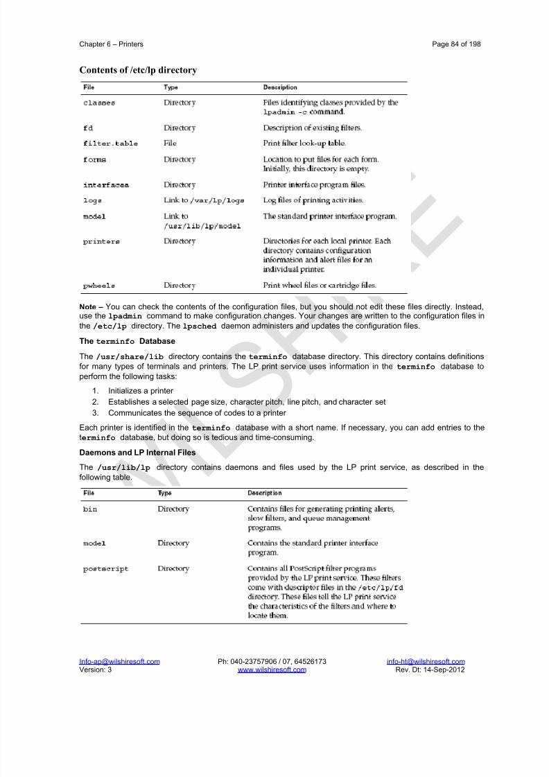
8/22/2019 Solaris%2010%20Handbook.pdf
http://slidepdf.com/reader/full/solaris201020handbookpdf 84/198
Chapter 6 – Printers Page 84 of 198
[email protected] Ph: 040-23757906 / 07, 64526173 [email protected] Version: 3 www.wilshiresoft.com Rev. Dt: 14-Sep-2012
Contents of /etc/lp directory
Note – You can check the contents of the configuration files, but you should not edit these files directly. Instead,use the lpadmin command to make configuration changes. Your changes are written to the configuration files in
the /etc/lp directory. The lpsched daemon administers and updates the configuration files.
The terminfo Database
The /usr/share/lib directory contains the terminfo database directory. This directory contains definitionsfor many types of terminals and printers. The LP print service uses information in the terminfo database to
perform the following tasks:
1. Initializes a printer
2. Establishes a selected page size, character pitch, line pitch, and character set
3. Communicates the sequence of codes to a printer
Each printer is identified in the terminfo database with a short name. If necessary, you can add entries to theterminfo database, but doing so is tedious and time-consuming.
Daemons and LP Internal Files
The /usr/lib/lp directory contains daemons and files used by the LP print service, as described in the
following table.

8/22/2019 Solaris%2010%20Handbook.pdf
http://slidepdf.com/reader/full/solaris201020handbookpdf 85/198
Chapter 6 – Printers Page 85 of 198
[email protected] Ph: 040-23757906 / 07, 64526173 [email protected] Version: 3 www.wilshiresoft.com Rev. Dt: 14-Sep-2012
LP Print Service Log Files
The LP print service maintains two sets of log files that are described in the following table.
Spooling Directories
Files queued for printing are stored in the /var/spool/lp directory until they are printed, which might be only
seconds.
How LP Administers Files and Schedules Local Print Requests
The LP print service has a scheduler daemon called lpsched . The scheduler daemon updates the LP system
files with information about printer setup and configuration. The lpsched daemon schedules all local print
requests on a print server, as shown in the following figure. Users can issue the requests from an application or
from the command line. Also, the scheduler tracks the status of printers and filters on the print server. When aprinter finishes a request, the scheduler schedules the next request n the queue on the print server, if a nextrequest exists.
Without rebooting the system, you can stop the scheduler with the svcadm disable application/print/server command. Then, restart the scheduler with the svcadm enable application/print/server command. The scheduler for each system manages requests that are issued to the system by the lp command.
How Remote Printing Works
The following figure shows what happens when a user on a Solaris print client submits a print request to an lpd-based print server. The command opens a connection and handles its own communications with the print server directly.

8/22/2019 Solaris%2010%20Handbook.pdf
http://slidepdf.com/reader/full/solaris201020handbookpdf 86/198
Chapter 6 – Printers Page 86 of 198
[email protected] Ph: 040-23757906 / 07, 64526173 [email protected] Version: 3 www.wilshiresoft.com Rev. Dt: 14-Sep-2012
Printing Service Commands
lpadmin Printer setup and few management aspects.
printmgr Graphical printer setup tool.
lpusers Manages printer job priorities.
lpmove Changes the destination of print jobs in the spool area.
lpforms Manages forms and associated parameters.
lpshut Stops the entire printing service.
lpsched Starts the printing service.
lpset Defines printer configuration in /etc/printers.conf..
lp Submits print jobs.
lpstat Displays the status of the printing service and the status of individual jobs and printers.
cancel Stops individual print jobs.
enable Starts a printer printing.
disable Stops printing on a particular printer.
accept Starts print jobs accumulating in the print spool for a particular printer.
reject Stops the print service from accepting jobs to be put in the printer spool area for printing ona particular printer.

8/22/2019 Solaris%2010%20Handbook.pdf
http://slidepdf.com/reader/full/solaris201020handbookpdf 87/198
Chapter 7 – System Processes & Job Automation Page 87 of 194
[email protected] Ph: 040-23757906 / 07, 64526173 [email protected] Version: 3 www.wilshiresoft.com Rev. Dt: 14-Sep-2012
7. System Processes & Job Automation Administering Solaris systems can be a t ime-consuming process. Simply keeping track of system files could be afull-time job, let alone managing security and user accounts. Let’s loo k at few of the tools to automate ceratinmundane system administration chores.
7.1. Updating System FilesOne of the most frequent housekeeping jobs an administrator faces is keeping system files current. For example,an administrator at a small site might manage 25 to 30 machines. Each machine has a private copy of the/usr/lib/sendmail software installed on the local disk. How could the administrator efficiently update the sendmailsoftware on 30 machines?
rdist command
The /bin/rdist command is a remote file distribution utility. The rdist utility allows the administrator to set up acentral repository of files which must be updated on multiple machines within the corporate network. To update allmachines on the network, the administrator makes changes to the files in the central repository, and then usesrdist utility to distribute these files to the other hosts on the network.
7.2. System Automation with Shell Scripts
The UNIX shell is an interactive programming language, as well as command interpreter. The shell executescommands received directly from the user sitting at the terminal. Alternately, the shell can execute commandsreceived from a file. A file containing shell-programming commands is called a shell file, or shell script.
Many of the operations performed by a sys-admin are accomplished by typing commands at the terminal. Due tofile access permissions, these commands must often be issued by root. The standard shell for root is /sbin/sh, astatically linked version of the Bourne shell. On the other hand, the program in /usr/bin/sh is a dynamically linkedversion of the Bourne shell.
(A statically linked program is one that links all library functions at compile time. If changes made to a libraryfunction due to compiler or other system software upgrades, the program must be recompiled to take advantageof those changes. A statically linked program will usually be quite large because it includes all library functions.
A dynamically linked program loads the library functions at run-time, which allows the program to include latestversion of all library functions upon invocation. No recompilation is required to enjoy the advantages of updated
library routines. Dynamically linked programs are usually smaller than statically linked counterparts because thelibrary functions are not included in the on-disk binary image.)
7.3. Automating Commands with cron and at
You can set up many system tasks to execute automatically. Some of these tasks should occur at regular intervals. Other tasks need to run only once, perhaps during off hours such as evenings or weekends.
The crontab command schedules repetitive commands. The at command schedules tasks that execute once.
The above table summarizes the commands
For Scheduling Repetitive Jobs: crontab
You can schedule routine system administration tasks to execute daily, weekly, or monthly by using the crontabcommand. Daily crontab system administration tasks might include the following:

8/22/2019 Solaris%2010%20Handbook.pdf
http://slidepdf.com/reader/full/solaris201020handbookpdf 88/198
Chapter 7 – System Processes & Job Automation Page 88 of 194
[email protected] Ph: 040-23757906 / 07, 64526173 [email protected] Version: 3 www.wilshiresoft.com Rev. Dt: 14-Sep-2012
Removing files more than a few days old from temporary directories
Executing accounting summary commands
Taking snapshots of the system by using the df and ps commands
Performing daily security monitoring
Running system backups
Weekly crontab system administration tasks might include the following:
Rebuilding the catman database for use by the man -k command
Running the fsck -n command to list any disk problems
Monthly crontab system administration tasks might include the following:
Listing files not used during a specific month
Producing monthly accounting reports
Additionally, users can schedule crontab commands to execute other routine system tasks, such as sendingreminders and removing backup files.
For Scheduling a Single Job: at
The at command allows you to schedule a job for execution at a later time. The job can consist of a singlecommand or a script. Similar to crontab, the at command allows you to schedule the automatic execution of routine tasks. However, unlike crontab files, at files execute their tasks once. Then, they are removed from their
directory. Therefore, the at command is most useful for running simple commands or scripts that direct output intoseparate files for later examination. Submitting an at job involves typing a command and following the atcommand syntax to specify options to schedule the time your job will be executed. The at command stores thecommand or script you ran, along with a copy of your current environment variable, in the /var/spool/cron/atjobsdirectory. Your at job file name is given a long number that specifies its location in the at queue, followed by the .aextension, such as 793962000.a. The cron daemon checks for at jobs at startup and listens for new jobs that aresubmitted. After the cron daemon executes an at job, the at job’s file is removed from the atjobs directory.
7.3.1. Scheduling a Repetitive System Task (cron)
The cron daemon schedules system tasks according to commands found within each crontab file. A crontab fileconsists of commands, one command per line, that will be executed at regular intervals. The beginning of eachline contains date and time information that tells the cron daemon when to execute the command. For example, acrontab file named root is supplied during SunOS software installation. The file’s contents include these command
lines:10 3 * * * /usr/sbin/logadm (1)
15 3 * * 0 /usr/lib/fs/nfs/nfsfind (2)
1 2 * * * [ -x /usr/sbin/rtc ] && /usr/sbin/rtc -c > /dev/null 2>&1 (3)
30 3 * * * [ -x /usr/lib/gss/gsscred_clean ] && /usr/lib/gss/gsscred_clean (4)
The following describes the output for each of these command lines:
The first line runs the logadm command at 3:10 a.m. every day.
The second line executes the nfsfind script every Sunday at 3:15 a.m.
The third line runs a script that checks for daylight savings time (and make corrections, if necessary) at2:10 a.m. daily. If there is no RTC time zone, nor an /etc/rtc_config file, this entry does nothing.
x86 only – The /usr/sbin/rtc script can only be run on an x86 based system.
The fourth line checks for (and removes) duplicate entries in the Generic Security Service table,/etc/gss/gsscred_db, at 3:30 a.m. daily.
The crontab files are stored in the /var/spool/cron/crontabs directory. Several crontab files besides root areprovided during SunOS software installation. See the following table:

8/22/2019 Solaris%2010%20Handbook.pdf
http://slidepdf.com/reader/full/solaris201020handbookpdf 89/198
Chapter 7 – System Processes & Job Automation Page 89 of 194
[email protected] Ph: 040-23757906 / 07, 64526173 [email protected] Version: 3 www.wilshiresoft.com Rev. Dt: 14-Sep-2012
Besides the default crontab files, users can create crontab files to schedule their own system tasks. Other crontabfiles are named after the user accounts in which they are created, such as bob, mary, smith, or jones. To accesscrontab files that belong to root or other users, superuser privileges are required. Procedures explaining how tocreate, edit, display, and remove crontab files are described in subsequent sections.
How the cron Daemon Handles Scheduling
cron daemon manages automatic scheduling of crontab commands. The role of cron daemon is to check/var/spool/cron/crontab directory for the presence of crontab files. The cron daemon performs the
following tasks at startup:
Checks for new crontab files
Reads the execution times that are listed within the files Submits the commands for execution at the proper times
Listens for notifications from the crontab commands regarding updated crontab files.
In much the same way, the cron daemon controls the scheduling of at files. These files are stored in the/var/spool/cron/atjobs directory. The cron daemon also listens for notifications from the crontab
commands regarding submitted at jobs.
Syntax of crontab File Entries
A crontab file consists of commands, one command per line that execute automatically at the time specified bythe first five fields of each command line. These five fields, described in the following table, are separated byspaces.
Follow these guidelines for using special characters in crontab time fields:
Use a space to separate each field.
Use a comma to separate multiple values.
Use a hyphen to designate a range of values.
Use an asterisk as a wildcard to include all possible values. Use a comment mark (#) at the beginning of a line to indicate a comment or a blank line.
For example, the following crontab command entry displays a reminder in the user’s console window at 4 p.m. onthe first and fifteenth days of every month.
0 16 1,15 * * echo Timesheets Due > /dev/console
Each command within a crontab file must consist of one line, even if that line is very long. The crontab file doesnot recognize extra carriage returns.
Controlling Access to the crontab Command

8/22/2019 Solaris%2010%20Handbook.pdf
http://slidepdf.com/reader/full/solaris201020handbookpdf 90/198
Chapter 7 – System Processes & Job Automation Page 90 of 194
[email protected] Ph: 040-23757906 / 07, 64526173 [email protected] Version: 3 www.wilshiresoft.com Rev. Dt: 14-Sep-2012
You can control access to the crontab command by using two files in the /etc/cron.d directory: cron.deny andcron.allow. These files permit only specified users to perform crontab command tasks such as creating, editing,displaying, or removing their own crontab files. The cron.deny and cron.allow files consist of a list of user names,one user name per line. These access control files work together as follows:
If cron.allow exists, only the users who are listed in this file can create, edit, display, or remove crontabfiles.
If cron.allow does not exist, all users can submit crontab files, except for users who are listed incron.deny.
If neither cron.allow nor cron.deny exists, superuser privileges are required to run the crontab command.
Superuser privileges are required to edit or create the cron.deny and cron.allow files. The cron.deny file, which iscreated during SunOS software installation, contains the following user names:
$ cat /etc/cron.d/cron.deny
daemon
bin
smtp
nuucp
listen
nobody
noaccess
None of the user names in the default cron.deny file can access the crontab command. You can edit this file toadd other user names that will be denied access to the crontab command. No default cron.allow file is supplied.So, after Solaris software installation, all users (except users who are listed in the default cron.deny file) canaccess the crontab command. If you create a cron.allow file, only these users can access the crontab command.
How to Verify Limited crontab Command Access
To verify if a specific user can access the crontab command, use the crontab –l command while you are loggedinto the user account.
$ crontab -l
If user can access crontab command, and already has created a crontab file, the file is displayed. Otherwise, if the user can access crontab command but no crontab file exists, a message similar to following message isdisplayed:
crontab: can’t open your crontab file
Either this user either is listed in the cron.allow file (if the file exists), or the user is not listed in the cron.deny file. If the user cannot access the crontab command, the following message is displayed whether or not a previouscrontab file exists:
crontab: you are not authorized to use cron. Sorry.
This message means that either the user is not listed in the cron.allow file (if the file exists), or the user is listed inthe cron.deny file.
7.3.2. Scheduling a Single System Task (at)
The following sections describe how to use the at command to perform the following tasks:
Schedule jobs (command and scripts) for execution at a later time
How to display and remove these jobs
How to control access to the at command
By default, users can create, display, and remove their own at job files. To access at files that belong to root or other users, you must have superuser privileges. When you submit an at job, it is assigned a job identificationnumber along with the .a extension. This designation becomes the job’s file name, as well as its queue number.
Description of the at Command
Submitting an at job file involves these steps:
1. Invoking the at utility and specifying a command execution time

8/22/2019 Solaris%2010%20Handbook.pdf
http://slidepdf.com/reader/full/solaris201020handbookpdf 91/198
Chapter 7 – System Processes & Job Automation Page 91 of 194
[email protected] Ph: 040-23757906 / 07, 64526173 [email protected] Version: 3 www.wilshiresoft.com Rev. Dt: 14-Sep-2012
2. Typing a command or script to execute later
For example, the following at job removes core files from the user account smith near midnight on the last day of July.
$ at 11:45pm July 31
at> rm /home/smith/*core*
at> Press Control-d
commands will be executed using /bin/csh
job 933486300.a at Tue Jul 31 23:45:00 2004
Controlling Access to the at Command
You can set up a file to control access to the at command, permitting only specified user s to create, remove, or display queue information about their at jobs. The file that controls access to the at command, /etc/cron.d/at.deny,consists of a list of user names, one user name per line. The users who are listed in this file cannot access atcommands. The at.deny file, which is created during SunOS software installation, contains the following user names:
daemon
bin
smtp
nuucp
listennobody
noaccess
With superuser privileges, you can edit the at.deny file to add other user names whose at command access youwant to restrict.
7.4. Viewing System Processes
A process is any program that is running on the system. All processes are assigned a unique processidentification (PID) number, which is used by the kernel to track and manage the process. The PID numbers areused by the root and regular users to identify and control their processes.
Using the CDE Process Manager
The Solaris OE Common Desktop Environment (CDE) provides a Process Manager to monitor and controlprocesses that are running on the local system.
Using the prstat Command
The prstat command examines and displays information about active processes on the system. This commandenables you to view information by specific processes, user identification (UID) numbers, central processing unit(CPU) IDs, or processor sets. By default, the prstat command displays information about all processes sorted byCPU usage. To use the prstat command, perform the command:
# prstat
To quit the prstat command, type q.
Note – The kernel and many applications are now multithreaded. A thread is a logical sequence of programinstructions written to accomplish a particular task. Each application thread is independently scheduled to run on
an LWP, which functions as a virtual CPU. LWPs in turn, are attached to kernel threads, which are scheduled torun on actual CPUs.
Note – Use the priocntl (1) command to assign processes to a priority class and to manage process priorities.The nice (1) command is only supported for backward compatibility to previous Solaris OE releases. The priocntlcommand provides more flexibility in managing processes.
Clearing Frozen Processes
You use the kill command or the pkill command to send a signal to one or more running processes. You wouldtypically use these commands to terminate or clear an unwanted process.

8/22/2019 Solaris%2010%20Handbook.pdf
http://slidepdf.com/reader/full/solaris201020handbookpdf 92/198
Chapter 7 – System Processes & Job Automation Page 92 of 194
[email protected] Ph: 040-23757906 / 07, 64526173 [email protected] Version: 3 www.wilshiresoft.com Rev. Dt: 14-Sep-2012
Using the kill and pkill Commands
You use the kill or pkill commands to terminate one or more processes. The format for the kill command is:
kill -signal PID
The format for the pkill command is:
pkill -signal Process
Before you can terminate a process, you must know its name or PID. Use either the ps or pgrep command tolocate the PID for the process. The following examples use the pgrep command to locate the PID for the mailprocesses.
$ pgrep -l mail
551 sendmail
12047 dtmail
$
$ pkill dtmail
The following examples use the ps and pkill commands to locate and terminate the dtmail process.
# ps -e |grep mail
314 ? 0:00 sendmail
1197 ? 0:01 dtmail# kill 1197
To terminate more than one process at the same time, use the following syntax:
$ kill signal PID PID PID PID
$ pkill signal process process
You use the kill command without a signal on the command line to send the default Signal 15 to the process. Thissignal usually causes the process to terminate.
1 - SIGHUP – A hangup signal to cause a telephone line or terminal connection to be dropped. For certain daemons, such as inetd and in.named, a hangup signal will cause daemon to reread itsconfiguration file.
2 - SIGINT – An interrupt signal from your keyboard—usually from a Control-C key combination.
9 - SIGKILL – A signal to kill a process. A process cannot ignore this signal.
15 - SIGTERM – A signal to terminate a process in an orderly manner. Some processes ignore thissignal.
A complete list of signals that the kill command can send can be found by executing the command kill -l, or byreferring to the man page for signal:
# man -s3head signal
Some processes can be written to ignore Signal 15. Processes that do not respond to a Signal 15 can beterminated by force by using Signal 9 with the kill or pkill commands. You use the following syntax:
$ kill -9 PID
$ pkill -9 process
Caution – Use the kill -9 or pkill -9 command as a last resort to terminate a process. Using kill -9 on a processthat controls a database application or a program that updates files can be disastrous. The process is terminated
instantly with no opportunity to perform an orderly shutdown.
Performing a Remote Login
When a workstation is not responding to your keyboard or mouse input, CDE might be frozen. In such cases, youmay be able to remotely access your workstation by using rlogin command or by using telnet command from
another system.

8/22/2019 Solaris%2010%20Handbook.pdf
http://slidepdf.com/reader/full/solaris201020handbookpdf 93/198
Chapter 7 – System Processes & Job Automation Page 93 of 194
[email protected] Ph: 040-23757906 / 07, 64526173 [email protected] Version: 3 www.wilshiresoft.com Rev. Dt: 14-Sep-2012
Killing the Process for a Frozen Login
After you are connected remotely to your system, you can invoke the pkill command to terminate the corruptedsession on your workstation. In the following example, the rlogin command is used to log in to sys42, from whichyou can issue a pkill command.
$ rlogin sys42
Password: EnterPassword
Last login: Mon Jan 14 10:11:56 from sys43Sun Microsystems Inc. SunOS 5.9 Beta May 2002
$ pkill -9 Xsun
or
$ pkill -9 Xsun

8/22/2019 Solaris%2010%20Handbook.pdf
http://slidepdf.com/reader/full/solaris201020handbookpdf 94/198
Chapter 8 – Backup and Restore Page 94 of 198
[email protected] Ph: 040-23757906 / 07, 64526173 [email protected] Version: 3 www.wilshiresoft.com Rev. Dt: 14-Sep-2012
8. Backup and Restore
8.1. Fundamentals of Backups
System administrator’s most important task is to ensure the availability of user data. Every file, every database,every byte of information stores on the system must be available. This requirement dictates the need for backup
copies of all data in the event there is a need to retrieve such information at a later date.However, making a copy of the data and storing it in another office in the same building may not be a solution tothe problem. For instance, in the event of a natural calamity the corporation may need to have copies of the datain remote locations to ensure survivability and accessibility of the backup media.
In the event of h/w failure or some other form of disaster, the system administrator sho uld be able to reload thebulk of user information from backup media. There will always be some loss of information. It is impossible tobackup every keystroke as it occurs. Therefore it is possible to lose information entered into the system betweenbackups. The goal of a backup procedure is to minimize data loss and allow the corporation to reload quickly andcontinue with business.
Which Files should be Backed Up?
Backing up all files on the system at regular intervals is good practice. Some files, however rarely change. Theadministrator needs to examine the content of system disks to identify the files that should be part of the filesystem backups, as well as files to be eliminated from regular backups.
Some programs are part of the OS. Administrators often decide not to backup the OS binaries, opting to reloadthem from the distribution media in the event of a loss. This practice requires making a backup of any OS relatedfiles that are created or changed. A few examples might be the NIS+ database, the password file, shadow file, rcfiles, and customizations that effect these files.
Another set of f iles that may be eliminated from regular backups are vendor-supplied binaries. If the distributionmedia for commercially purchased software is available, regular backups of these files are not necessary. Again,the administrator should ensure that any customized files or start-up scripts required for those packages are onthe backup list.
Files that should be backed up regularly include user files, corporate databases or other important data, and filesthat have been changed since the time of the last backup. On large systems the amount of data to be backed upmay exceed several GBs a day. Consequently, the administrator should decide how and when to performbackups in order to minimize impact on the system and loss of important data.
Backup Frequency

8/22/2019 Solaris%2010%20Handbook.pdf
http://slidepdf.com/reader/full/solaris201020handbookpdf 95/198
Chapter 8 – Backup and Restore Page 95 of 198
[email protected] Ph: 040-23757906 / 07, 64526173 [email protected] Version: 3 www.wilshiresoft.com Rev. Dt: 14-Sep-2012
Frequency is another very important factor in successful file system backup strategies. The administrator mustdetermine how much can be lost before seriously affecting the organizations ability to do business. Corporationsthat use computers for financial transactions, stock and commodities trading, and insurance activities would be afew examples, which don’t allow any data loss. In these cases the loss of a single transaction is not acceptable.
A reasonable backup schedule for a typical corporation would call for some form of backup to be performedeveryday. In addition, the backups must be performed every day so that the operator knows which tape to use toreload, and to force the administrator into a schedule. The fact that backups must be maintained on a rigid
schedule lends support to the automated backup methods.
Backup Scheduling
After determining the files to backup and the frequency of backup, its time to decide about the backup scheduleand also the devices to be used for backup.
8.2. Types of Backups
Several types of backups may be performed, and the simplest type is a full dump. A full dump is also referred toas a level 0 dump. A full dump copies every disk file to the backup media. On systems with large disk storagecapacity, it might not be possible to make full dumps very often due to the cost of the tapes, tape storage spacerequirements, and the amount of time required to copy files to the tapes. Because full dumps are expensive interms of time and resources, most programs written to perform backups allow for some form of incremental dump.In an incremental dump, files created or modified since the last dump are copied to the backup media. For
example, if a full dump is performed on a Sunday, the Monday incremental dump would contain only the filescreated or changed since the last Sunday dump.
The type of dump to be performed will typically rely on the chosen backup strategy. The strategy includes factorssuch as how long to keep copies of the dump media on hand, what type of dump to perform on which day of theweek, and how easily information can be restored from the backup media. In order to ensure successful dumps, itis recommended that the system be shut down to the single-user init state.
Typical Backup Strategies
Full dumps allow you to establish a snapshot of the system at a given point in time. All corporate data should becontained on a full dump. Incremental dumps allow the administrator to recover active files with a minimum of media and time. In case of incremental dumps, a level N dump will backup all files altered or created since thelast dump at a lower level.
Backup Interval Terms and Definitions

8/22/2019 Solaris%2010%20Handbook.pdf
http://slidepdf.com/reader/full/solaris201020handbookpdf 96/198
Chapter 8 – Backup and Restore Page 96 of 198
[email protected] Ph: 040-23757906 / 07, 64526173 [email protected] Version: 3 www.wilshiresoft.com Rev. Dt: 14-Sep-2012
Volume Calendar BackupLet us examine 3 of the popular backup strategies:
1. Volume/Calendar Backup
2. Grandfather/Father/Son Backup
3. Tower of Hanoi Backup
Volume/Calendar Backup
This strategy calls for a full system backup once a month. An incremental backupis performed once a week for files that change often. Daily incremental backupscatch the files that have changed since the last daily backup.
A typical schedule would be to perform the full (level 0) backup one Sunday amonth, and weekly level 3 backups every Sunday of the month. Daily level 5backups would be performed Monday through Saturday. This would require eightcomplete sets of media (one monthly tape, one weekly tape, and six daily tapes).
Recovering from complete data loss with the volume/calendar scheme requiresrestoring from the most recent full backup, then restoring from the most recentweekly backup, and finally, restoring from each daily backup tape written since theweekly backup.
An advantage to this backup scheme is that it requires a minimum of media. Oneproblem with this backup scheme is that the tapes are immediately reused. For example, every Monday overwrites last Monday’s backup information. Consider what would happen if one disk drives fail during second Monday backup. It wouldnot be possible to recover all the data, because the system was in the process of overwriting the backup tape when the drive failed.
Grandfather /Father /Son Backup
This strategy is similar to the volume/calendar strategy. The major differencebetween the 2 schemes is that this method incorporates a one-month archive inthe backup scheme. This eliminates the problem of overwriting a tape beforecompleting a more recent backup of the file system.
Implementing this strategy requires performing a full dump once a month to new
media. Once a week, an incremental (level 3) backup must be performed whichcaptures all files changed since the last weekly backup. This weekly backupshould also be saved on new media. Each day, an incremental level 5 backupmust be performed to capture files that have changed since the last daily backup.The daily backups reuse the tapes written one week earlier.
Day Date Level
Tape
Sun Date 1 0 AMon Date 2 5 B
Tue Date 3 5 C
Wed Date 4 5 D
Thu Date 5 5 E
Fri Date 6 5 F
Sat Date 7 5 G
Sun Date 8 3 H
Mon Date 9 5 B
Tue Date 10 5 C
Wed Date 11 5 D
Thu Date 12 5 E
Fri Date 13 5 FSat Date 14 5 G
Sun Date 15 3 H
Mon Date 16 5 B
Tue Date 17 5 C
Wed Date 18 5 D
Thu Date 19 5 E
Fri Date 20 5 F
Sat Date 21 5 G
Sun Date 22 3 H
Mon Date 23 5 B
Tue Date 24 5 C
Wed Date 25 5 D
Thu Date 26 5 E
Fri Date 27 5 F
Sat Date 28 5 G
Sun Date 29 3 H
Mon Date 30 5 B
Tue Date 31 5 C

8/22/2019 Solaris%2010%20Handbook.pdf
http://slidepdf.com/reader/full/solaris201020handbookpdf 97/198
Chapter 8 – Backup and Restore Page 97 of 198
[email protected] Ph: 040-23757906 / 07, 64526173 [email protected] Version: 3 www.wilshiresoft.com Rev. Dt: 14-Sep-2012
GRANDFATHER/FATHER/SON BACKUP
Day Date Level
Tape
Day Date Level
Tape
Day Date Level
Tape
Sun Date 1 0 A Wed Date 1 5 D Wed Date 1 5 D
Mon Date 2 5 B Thu Date 2 5 E Thu Date 2 5 E
Tue Date 3 5 C Fri Date 3 5 F Fri Date 3 5 F
Wed Date 4 5 D Sat Date 4 3 M Sat Date 4 3 K
Thu Date 5 5 E Sun Date 5 5 H Sun Date 5 5 H
Fri Date 6 5 F Mon Date 6 5 B Mon Date 6 5 B
Sat Date 7 3 G Tue Date 7 5 C Tue Date 7 5 C
Sun Date 8 5 H Wed Date 8 5 D Wed Date 8 5 D
Mon Date 9 5 B Thu Date 9 5 E Thu Date 9 5 E
Tue Date 10 5 C Fri Date 10 5 F Fri Date 10 5 F
Wed Date 11 5 D Sat Date 11 3 G Sat Date 11 3 MThu Date 12 5 E Sun Date 12 5 H Sun Date 12 5 H
Fri Date 13 5 F Mon Date 13 5 B Mon Date 13 5 B
Sat Date 14 3 I Tue Date 14 5 C Tue Date 14 5 C
Sun Date 15 5 H Wed Date 15 5 D Wed Date 15 5 D
Mon Date 16 5 B Thu Date 16 5 E Thu Date 16 5 E
Tue Date 17 5 C Fri Date 17 5 F Fri Date 17 5 F
Wed Date 18 5 D Sat Date 18 3 I Sat Date 18 3 G
Thu Date 19 4 E Sun Date 19 5 H Sun Date 19 5 H
Fri Date 20 5 F Mon Date 20 5 B Mon Date 20 5 B
Sat Date 21 3 J Tue Date 21 5 C Tue Date 21 5 C
Sun Date 22 5 H Wed Date 22 5 D Wed Date 22 5 D
Mon Date 23 5 B Thu Date 23 5 E Thu Date 23 5 ETue Date 24 5 C Fri Date 24 5 F Fri Date 24 5 F
Wed Date 25 5 D Sat Date 25 3 J Sat Date 25 3 I
Thu Date 26 5 E Sun Date 26 0 A Sun Date 26 0 L
Fri Date 27 5 F Mon Date 27 5 A Mon Date 27 5 B
Sat Date 28 3 K Tue Date 28 5 C Tue Date 28 5 C
Sun Date 29 0 L Wed Date 29 5 D
Mon Date 30 5 B Thu Date 30 5 E
Tue Date 31 5 C Fri Date 31 5 F

8/22/2019 Solaris%2010%20Handbook.pdf
http://slidepdf.com/reader/full/solaris201020handbookpdf 98/198
Chapter 8 – Backup and Restore Page 98 of 198
[email protected] Ph: 040-23757906 / 07, 64526173 [email protected] Version: 3 www.wilshiresoft.com Rev. Dt: 14-Sep-2012
Typical Scheduling for the Tower of Hanoi Backup Strategy
Tower of Hanoi Backup
The Tower of Hanoi backup strategy is avariation of “exponential backup.” Both
strategies rely on mathematical functions of powers of 2. For example, the use of fivebackup tapes provides for a 32-dayschedule. The use of 6 tapes would providefor a 64-day schedule.
The Tower of Hanoi backup scheduleprovides outstanding data survivability anda minimum of media. Unfortunately, on a 7-day backup system, the scheduling of fullbackups as opposed to partial backups canbecome a problem for the operator.
One way to avoid operator confusion is toperform a special level 0 backup on the first
day of each month. This tape would not beone of the five tapes used in the backupcycle. Total media requirements in thisscheme would be seven sets of media.
To recover from complete data loss, firstrestore from the most recent level 0backup, and then restore from the level 1backup if that backup was written after thelevel 0 backup. Next, restore consecutivelyfrom the most recent level 3 and 4 backupsif both were written after the level 0 backup.Finally, restore each of the level 5 backupsthat were written after the level 0 backup.Finally, restore each of the level 5 backupsthat were written after the level 0 backup.
Day Date Level
Tape
Day Date Leve
l
Tape
Sun Date 1 0 E Wed Date 1 5 A
Mon Date 2 5 A Thu Date 2 0 E
Tue Date 3 4 B Fri Date 3 5 A
Wed Date 4 5 A Sat Date 4 4 B
Thu Date 5 3 C Sun Date 5 5 A
Fri Date 6 5 A Mon Date 6 3 C
Sat Date 7 4 B Tue Date 7 5 A
Sun Date 8 5 A Wed Date 8 4 B
Mon Date 9 1 D Thu Date 9 5 A
Tue Date 10 5 A Fri Date 10 1 D
Wed Date 11 4 B Sat Date 11 5 A
Thu Date 12 5 A Sun Date 12 4 B
Fri Date 13 3 C Mon Date 13 5 A
Sat Date 14 5 A Tue Date 14 3 C
Sun Date 15 4 B Wed Date 15 5 A
Mon Date 16 5 A Thu Date 16 4 B
Tue Date 17 0 E Fri Date 17 5 A
Wed Date 18 5 A Sat Date 18 0 E
Thu Date 19 4 B Sun Date 19 5 A
Fri Date 20 5 A Mon Date 20 4 B
Sat Date 21 3 C Tue Date 21 5 A
Sun Date 22 5 A Wed Date 22 3 C
Mon Date 23 4 B Thu Date 23 5 ATue Date 24 5 A Fri Date 24 4 B
Wed Date 25 1 D Sat Date 25 5 A
Thu Date 26 5 A Sun Date 26 1 D
Fri Date 27 4 B Mon Date 27 5 A
Sat Date 28 5 A Tue Date 28 4 B
Sun Date 29 3 C
Mon Date 30 5 A
Tue Date 31 4 B

8/22/2019 Solaris%2010%20Handbook.pdf
http://slidepdf.com/reader/full/solaris201020handbookpdf 99/198
Chapter 8 – Backup and Restore Page 99 of 198
[email protected] Ph: 040-23757906 / 07, 64526173 [email protected] Version: 3 www.wilshiresoft.com Rev. Dt: 14-Sep-2012
Typical Scheduling for a reasonable backup strategy
This table offers a reasonable backup schedule for most sites. Performing a fulldump of the first Sunday of the month provides a monthly snapshot of the systemdata. Using two sets of dump media allows the operator to store information for two full months.
Note that in the example the Tuesday through Friday incremental backups containextra copies of files from Monday. This schedule ensures that any file modifiedduring the week can be recovered from the previous days incremental dump.
To recover from complete data loss, restore the most recent full (level 0) backuptape. Next, restore from the most recent of the weekly (level 3) backups. Once theweekly backups are restored, restore from each of the daily (level 5) backups.
8.3. Types of Backup Devices
Once a backup strategy has been chosen, it is time to devote some attention tobackup devices. Principal backup device requirements follow:
User ability to write data to the device
Media capable of storing the data for long periods
Supports standard system interconnects Supports reasonable I/O throughput
Most devices used for system backups consist of magnetic media (tape or disk)and the drive mechanism. The drive mechanism provides the electronics andtransport functions to allow the device to store digital signals on the magneticmedia. Lets take a look at few of the backup devices.
Tape Backup Devices:
Tape backup devices are probably the most common backup media in use. Themedia is relatively inexpensive, the performance is reasonable, the data formatsare standardized, and tape drives are easy to use. These factors combined makemagnetic tape backups an attractive option. One complication of tape backups isdeciding which type of tape system to use. Several of the more popular optionsare explored in the following sections.
½-inch 9-Track Tape Drive
Half-inch tape drives were once the mainstay of backup media. The early ½-inchtape drives allowed the operator to write information on the tape at 800 bits per inch of tape. Later drives allowed 1600 bits per inch, and the most recent drivesallow 6250 bits per inch. At 6250 bits per inch, a ½ inch tape can hold up to 100Mb of information.
A typical 1/2 –inch tape consists of 2400 feet of ½-inch-wide tape on a 10-inchplastic reel. The ½-inch tape drives are typically large and expensive, but the tape itself is relatively inexpensive.The ½-inch format is still a standard media for many industrial operations.
Older ½-inch tape drives required special bus interfaces to connect them to a system, whereas the SCSI interfaceis common today. Due to the vast quantity of information stored on ½-inch tape, the ½-inch tape drive will berequired for many years to come simply to access the stored information. However, with systems containing
literally hundreds of gigabytes of disk storage, ½-inch tape becomes impractical for data backup.
Cartridge Tape Drive
Cartridge tape drives store between 10 Mb and several GB of data on a small tape cartridge. Cartridge tapedrives are usually smaller and less expensive than ½-inch tape drives. Tape cartridges are typically moreexpensive than a reel of ½-inch tape. Because the data cartridge stores more information, a cartridge tape mustbe manufactured to tighter tolerances than ½-inch tapes.
Because the media is smaller and the drives less expensive, cartridge tape systems have become standarddistribution media for many software companies. Moreover, cartridge tapes are particularly attractive for disaster recovery situations because many systems still include boot PROM code to boot cartridge distribution tapes.
Day Date Level
Tape
Sun Date 1
Mon Date 2 0 A
Tue Date 3 5 B
Wed Date 4 5 C
Thu Date 5 5 D
Fri Date 6 3 E
Sat Date 7
Sun Date 8
Mon Date 9 5 F
Tue Date 10 5 B
Wed Date 11 5 C
Thu Date 12 5 D
Fri Date 13 3 E
Sat Date 14
Sun Date 15
Mon Date 16 5 F
Tue Date 17 5 B
Wed Date 18 5 D
Thu Date 19 5 D
Fri Date 20 3 E
Sat Date 21
Sun Date 22
Mon Date 23 5 F
Tue Date 24 5 B
Wed Date 25 5 DThu Date 26 5 D
Fri Date 27 3 E
Sat Date 28
Sun Date 29
Mon Date 30 5 F
Tue Date 31 5 B

8/22/2019 Solaris%2010%20Handbook.pdf
http://slidepdf.com/reader/full/solaris201020handbookpdf 100/198
Chapter 8 – Backup and Restore Page 100 of 198
[email protected] Ph: 040-23757906 / 07, 64526173 [email protected] Version: 3 www.wilshiresoft.com Rev. Dt: 14-Sep-2012
A cartridge tape distribution of the OS is easily stored in a remote location. In the event of a failure or disaster atthe primary computer location, these distribution tapes could be used to rebuild a system to replace the damagedhost.
Most cartridge tape systems use SCSI interconnections to the host system. These devices support data transfer rate up to 5 Mb per second. This transfer rate may be a little misleading, however, as the information is typicallybuffered in memory of the tape drive. The actual transfer rate from the tape drive memory to the tape media istypically about 500 Kb per second.
8-mm Tape Drive
These tape drives are also small and fast, and use relatively inexpensive tape media. The 8-mm media can holdbetween 2 and 40 GB of data. Because of high-density storage, 8-mm drives have become a standard backupdevice on many systems. Several companies also use 8-mm tape as distribution media for software.
The 8-mm drives use the SCSI bus as the system interconnection. Low-density 8-mm drives can store 2.2 GB of information on tape. These units transfer data to the tape at a rate of 250 Kb per second. High-density 8-mmdrives can store between 5 and 40 GB of information on tape.
At the “low” end, the 8-mm drives don’t use data compression techniques to store the information on tape. At the“high” end, the drives incorporate data compression hardware used to increase the amount of information that canbe stored on the tape. Regardless of the use of data compression, high-density 8-mm drives transfer data to tapeat a rate of 500 Kb per second. High-density drives also allow the user to read and write data at the lower densities supported by the low-density drives. When using the high-density drives in low-density mode, storage
capacities and throughput numbers are identical to low-density drives.Digital Audio Tape Drive
Digital audio tape (DAT) drives are small, fast, and use relatively inexpensive tape media. Typical DAT media canhold between 2 and 40 GB of data. The DAT media is a relative newcomer to the digital data backup market. Thetape drive electronics and media are basically the same as the DAT tapes used in home audio systems.
The various densities available on DAT drives are due to data compression. A standard DAT drive can write 2 Gbof data to a tape. By using various data compression algorithms, manufacturers have produced drives that canstore between 2 and 40 GB of data on tape. DAT drives use SCSI bus interconnections to the host system.Because DAT technology is relatively new, it offers performance and features not available with other tape systemtechnologies. For instance, the DAT drive offers superior file search capabilities as compared to the 8-mm helicalscan drives on the market.
Digital Linear Tape (DLT)
Digital linear tape backup devices are among the newest devices on the backup market. These tape devices offer huge data storage capabilities, high transfer rates, and small (but somewhat costly) media. Digital linear tapedrives can store up to 70 GB of data on a single tape cartridge. Transfer rates of 5 Mb/second are possible onhigh-end DLT drives, making them very attractive at sites with large on-line storage systems.
Where 8-mm and DAT tape cost (roughly) $15 per tape, the DLT tapes can run as much as $60 each. However,when the tape capacity is factored into the equation, the costs of DLT tapes become much more reasonable.(Consider an 8-mm tape that holds 14 GB on average versus a DLT cartridge, which can hold 70 Gb of data.)
Many operators elect not to enable the compression hardware on tape systems, opting instead for softwarecompression before the data are sent to the tape drive. In the event of a hardware failure in the tape drivescompression circuitry, it is possible that the data written to tape would be scrambled. By using the softwarecompression techniques, the operator can bypass such potential problems.
Jukebox System
Jukebox systems combine a “jukebox” mechanism with one or more tape drives to provide a tape system capableof storing several hundred Gb of data. The tape drives in the jukebox systems employ multiple tape drives, andspecial “robotic” hardware to load and unload the tapes.
Jukebox systems require special software to control the robotics. The software keeps track of the content of eachtape and builds an index to allow the user to quickly load the correct tape on demand. Many commerciallyavailable backup software packages allow the use of jukebox systems to permit backup automation.
Disk Systems as backup devices

8/22/2019 Solaris%2010%20Handbook.pdf
http://slidepdf.com/reader/full/solaris201020handbookpdf 101/198
Chapter 8 – Backup and Restore Page 101 of 198
[email protected] Ph: 040-23757906 / 07, 64526173 [email protected] Version: 3 www.wilshiresoft.com Rev. Dt: 14-Sep-2012
One problem involved in using tape devices for backups is the (relatively) low data throughput rate. If the operator had to backup up several gigabytes or terabytes of data daily it would not take long to realize that tape drives arenot the best backup method.
One popular method of backing up large-scale systems is to make backup copies of the data on several diskdrives. Disk drives are orders of magnitude faster than tape devices, and therefore offer a solution to one of thebackup problems on large-scale systems. However, disk drives are much more expensive than tapes. Diskbackups also consume large amounts of system resources. For example, you would need 100 2-Gb disks to back
up a hundred 2-Gb disks. Fortunately, there are software applications and hardware systems available totransparently perform this function.
RAID Disk Arrays
One operating mode of redundant arrays of inexpensive disks (RAID) enables the system to make mirror imagecopies of all data on backup disk drives. RAID disk arrays also allow data striping for high-speed data access. Yetanother mode stores the original data, as well as parity information on the RAID disks. If a drive should fail, theparity information may be used to re-create the data from the failed drive.
Problems with Disks as Backup Devices
Although backing up to disk devices is much faster than backing up to other devices, it should be noted that diskdevices present a potentially serious problem. One of the important considerations of backup planning is theavailability of the data to users. In the event of a natural disaster, it may be necessary to keep a copy of thecorporate data off-site.
When tape devices are employed as the backup platform, it is a simple matter to keep a copy of the backups off-site. When disk drives are employed as a backup media, the process of keeping a copy of the backup media off-site becomes a bit more complicated (not to mention much more expensive). In the case of a RAID disk array, theprimary copy of the data is stored on another disk. However, both disks are housed in a single box. This makesthe task of moving one drive off-site much more complicated.
RAID disk arrays have recently been equipped with fiber channel interfaces. The fiber channel is a high-speedinterconnect that allows devices to be located several kilometers from the computer. By linking RAID disk arraysto systems via optical fibers, it is possible to have an exact copy of the data at a great distance from the primarycomputing site at all times.
In applications and businesses where data accessibility is of the utmost importance, the use of RAID disk arraysand fiber channel interconnections could solve most of the problems.
Differences between Different types of Backups

8/22/2019 Solaris%2010%20Handbook.pdf
http://slidepdf.com/reader/full/solaris201020handbookpdf 102/198
Chapter 8 – Backup and Restore Page 102 of 198
[email protected] Ph: 040-23757906 / 07, 64526173 [email protected] Version: 3 www.wilshiresoft.com Rev. Dt: 14-Sep-2012
Using Dump Levels to Create Incremental Backups
The dump level you specify in the ufsdump command (0 –9) determines which files are backed up. Dump level 0creates a full backup. Levels 1 –9 are used to schedule incremental backups, but have no defined meanings.Levels 1 –9 are just a range of numbers that are used to schedule cumulative or discrete backups. The onlymeaning levels 1 –9 have is in relationship to each other, as a higher or lower number. A lower dump number always restarts a full or a cumulative backup. The following examples show the flexibility of the incremental dumpprocedure using levels 1 –9.
Dump Levels for Daily, Incremental Backups
Daily Cumulative, Weekly Cumulative Backup Schedule and Tape Contents
Daily Cumulative, Weekly Incremental Backup Schedule and Tape Contents
Daily Incremental, Weekly Cumulative Backup Schedule and Tape Contents

8/22/2019 Solaris%2010%20Handbook.pdf
http://slidepdf.com/reader/full/solaris201020handbookpdf 103/198
Chapter 8 – Backup and Restore Page 103 of 198
[email protected] Ph: 040-23757906 / 07, 64526173 [email protected] Version: 3 www.wilshiresoft.com Rev. Dt: 14-Sep-2012
8.4. Commands for Copying File Systems
When you need to back up and restore complete file systems, use the ufsdump and ufsrestore commands. When
you want to copy or move individual files, portions of file systems, or complete file systems, you can use theprocedures described in this chapter instead of the ufsdump and ufsrestore commands. The following tabledescribes when to use the various backup commands.
Differences between the various backup commands

8/22/2019 Solaris%2010%20Handbook.pdf
http://slidepdf.com/reader/full/solaris201020handbookpdf 104/198
Chapter 8 – Backup and Restore Page 104 of 198
[email protected] Ph: 040-23757906 / 07, 64526173 [email protected] Version: 3 www.wilshiresoft.com Rev. Dt: 14-Sep-2012
Frequently used commands for copying File Systems
Making a Literal File System Copy
The dd command makes a literal (block-level) copy of a complete UFS file system to another file system or to a
tape. By default, the dd command copies standard input to standard output.
Note – Do not use the dd command with variable-length tape drives without first specifying an appropriate blocksize.
You can specify a device name in place of standard input or standard output, or both. In this example, thecontents of the diskette are copied to a file in the /tmp directory:
$ dd < /floppy/floppy0 > /tmp/output.file2400+0 records in
2400+0 records out
The dd command reports on the number of blocks it reads and writes. The number after the + is a count of thepartial blocks that were copied. The default block size is 512 bytes. The dd command syntax is different from
most other commands. Options are specified as keyword=value pairs, where keyword is the option you want toset and value is the argument for that option. For example, you can replace standard input and standard outputwith this syntax:
$ dd if=input-file of=output-file

8/22/2019 Solaris%2010%20Handbook.pdf
http://slidepdf.com/reader/full/solaris201020handbookpdf 105/198
Chapter 8 – Backup and Restore Page 105 of 198
[email protected] Ph: 040-23757906 / 07, 64526173 [email protected] Version: 3 www.wilshiresoft.com Rev. Dt: 14-Sep-2012
To use the keyword=value pairs instead of the redirect symbols, you would type the following:
$ dd if=/floppy/floppy0 of=/tmp/output.file
How to Copy a Disk (dd )
Keep the following key points in mind when you consider copying a disk:
1. Do not use this procedure to copy a disk that is under the control of a volume manager.2. The primary methods for copying UFS file system data from one disk or system to another disk or system
is by using the ufsdump and ufsrestore commands.
3. You can clone systems by creating a flash archive and copying it to destination systems.
4. If you are still considering copying a disk with the dd command keep the following cautions in mind:
5. Make sure that the source disk and destination disk have the same disk geometry.
6. Check the UFS file systems on the disk to be copied with the fsck utility.
7. Make sure the system is in single-user mode when copying a disk with the dd command.
Copying Files and File Systems to Tape
You can use the tar, pax, and cpio commands to copy files and file systems to tape. The command that you
choose depends on how much flexibility and precision you require for the copy. Because all three commands usethe raw device, you do not need to format or make a file system on tapes before you use them. The tape drive
and device name that you use depend on the hardware configuration for each system.
Copying Files to Tape (tar Command)
Here is information that you should know before you copy files to tape with the tar command:
Copying files to a tape with the -c option to the tar command destroys any files already on the tape at or beyond the current tape position.
You can use file name substitution wildcards (? and *) as part of the file names that you specify whencopying files. For example, to copy all documents with a .doc suffix, type *.doc as the file nameargument.
You cannot use file name substitution wildcards when you extract files from a tar archive.
Copying Files to a Tape With the pax Command
How to Copy Files to a Tape ( pax)
1. Change to the directory that contains the files you want to copy.
2. Insert a write-enabled tape into the tape drive.
3. Copy the files to tape.
$ pax -w -f /dev/rmt/n filenames
-w Enables the write mode.
-f /dev/rmt/n Identifies the tape drive.
filenames Indicates the files and directories that you want to copy.
Separate multiple files with spaces.
4. Verify that the files have been copied to tape.
$ pax -f /dev/rmt/n
5. Remove the tape from the drive. Write the names of the files on the tape label.
Copying Files to Tape With the cpio Command
How to Copy All Files in a Directory to a Tape (cpio)
1. Change to the directory that contains the files you want to copy.
2. Insert a write-enabled tape into the tape drive.
3. Copy the files to tape.
$ ls | cpio -oc > /dev/rmt/n

8/22/2019 Solaris%2010%20Handbook.pdf
http://slidepdf.com/reader/full/solaris201020handbookpdf 106/198
Chapter 8 – Backup and Restore Page 106 of 198
[email protected] Ph: 040-23757906 / 07, 64526173 [email protected] Version: 3 www.wilshiresoft.com Rev. Dt: 14-Sep-2012
ls Provides the cpio command with a list of file names.
cpio -oc Specifies that the cpio command should operate in copy-out mode (-o) and write header information in ASCII character format (-c). These options ensure portability to other vendors’ systems.
> /dev/rmt/n Specifies the output file.
All files in the directory are copied to the tape in the drive you specify, overwriting any existing files on the
tape. The total number of blocks that are copied is shown.4. Verify that the files have been copied to tape.
$ cpio -civt < /dev/rmt/n
-c Specifies that the cpio command should read files in ASCII character format.
-i Specifies that the cpio command should operate in copy-in mode, even though the command is
only listing files at this point.
-v Displays the output in a format that is similar to the output from the ls -l command.
-t Lists the table of contents for the files on the tape in the tape drive that you specify.
< /dev/rmt/n Specifies the input file of an existing cpio archive.
How to Retrieve All Files from a Tape (cpio)
If the archive was created using relative path names, the input files are built as a directory within the currentdirectory when you retrieve the files. If, however, the archive was created with absolute path names, the sameabsolute paths are used to re-create the file on your system.
1. Change to the directory where you want to put the files.
2. Insert the tape into the tape drive.
3. Extract all files from the tape.
$ cpio -icvd < /dev/rmt/n
-i Extracts files from standard input.
-c Specifies that the cpio command should read files in ASCII character format.
-v Displays the files as they are retrieved in a format that is similar to the output from the ls command.
-d Creates directories as needed.
< /dev/rmt/n Specifies the output file.
4. Verify that the files were copied.
$ ls -l
Retrieving All Files from a Tape (cpio)
The following example shows how to retrieve all files from the tape in drive 0.
$ cd /var/tmp
cpio -icvd < /dev/rmt/0
answers
sc.directives
tests
8 blocks$ ls -l
How to Retrieve Specific Files From a Tape (cpio)
1. Change to the directory where you want to put the files.
2. Insert the tape into the tape drive.
3. Retrieve a subset of files from the tape.
$ cpio -icv "*file" < /dev/rmt/n
-i Extracts files from standard input.

8/22/2019 Solaris%2010%20Handbook.pdf
http://slidepdf.com/reader/full/solaris201020handbookpdf 107/198
Chapter 8 – Backup and Restore Page 107 of 198
[email protected] Ph: 040-23757906 / 07, 64526173 [email protected] Version: 3 www.wilshiresoft.com Rev. Dt: 14-Sep-2012
-c Specifies that the cpio command should read headers in ASCII character format.
-v Displays the files as they are retrieved in a format that is similar to the output from the ls command.
"*file" Specifies that all files that match the pattern are copied to the current directory. You can specify multiplepatterns, but each pattern must be enclosed in double quotation marks.
< /dev/rmt/n Specifies the input file.
Verify that the files were copied.
$ ls -l
Retrieving Specific Files from a Tape (cpio)
The following example shows how to retrieve all files with the chapter suffix from the tape in drive 0.
$ cd /home/smith/Book
$ cpio -icv "*chapter" < /dev/rmt/0
Boot.chapter
Directory.chapter
Install.chapter
Intro.chapter
31 blocks
$ ls -l
Copying Files to a Remote Tape Device
How to Copy Files to a Remote Tape Device (tar and dd )
1. The following prerequisites must be met to use a remote tape drive:
a. The local host name and optionally, the user name of the user doing the copy, mustappear in the remote system’s /etc/hosts.equiv file. Or, the user doing the copy
must have his or her home directory accessible on the remote machine, and have thelocal machine name in $HOME/.rhosts.
b. An entry for the remote system must be in the local system’s /etc/inet/hosts file
or in the name service hosts file.
2. To test whether you have the appropriate permission to execute a remote command, try the following:
$ rsh remotehost echo testIf test is echoed back to you, you have permission to execute remote commands. If Permission denied is
echoed back to you, check your setup as described in Step 1.
3. Change to the directory where you want to put the files.
4. Insert the tape into the tape drive.
5. Copy the files to a remote tape drive.
$ tar cvf - filenames | rsh remote-host dd of=/dev/rmt/n obs=block-size
tar cf Creates a tape archive, lists the files as they are archived, and specifies the tape device.
v Provides additional information about the tar file entries.
- (Hyphen) Represents a placeholder for the tape device.
filenames Identifies the files to be copied. Separate multiple files with spaces.
rsh | remote-host Pipes the tar command’s output to a remote shell.
dd of= /dev/rmt/n Represents the output device.
obs=block-size Represents the blocking factor.
6. Remove the tape from the drive. Write the names of the files on the tape label.
Copying Files to a Remote Tape Drive (tar and dd )
# tar cvf - * | rsh mercury dd of=/dev/rmt/0 obs=126b

8/22/2019 Solaris%2010%20Handbook.pdf
http://slidepdf.com/reader/full/solaris201020handbookpdf 108/198
Chapter 8 – Backup and Restore Page 108 of 198
[email protected] Ph: 040-23757906 / 07, 64526173 [email protected] Version: 3 www.wilshiresoft.com Rev. Dt: 14-Sep-2012
a answers/ 0 tape blocks
a answers/test129 1 tape blocks
a sc.directives/ 0 tape blocks
a sc.directives/sc.190089 1 tape blocks
a tests/ 0 tape blocks
a tests/test131 1 tape blocks
6+9 records in0+1 records out
How to Extract Files from a Remote Tape Device
1. Insert the tape into the tape drive.
2. Change to a temporary directory.
$ cd /var/tmp
3. Extract the files from a remote tape device.
$ rsh remote-host dd if=/dev/rmt/n | tar xvBpf -
rsh remote-host Indicates a remote shell that is started to extract the files from the tape device by usingthe dd command.
dd if=/dev/rmt/n Indicates the input device.
| tar xvBpf - Pipes the output of the dd command to the tar command, which is used to restore
the files.
4. Verify that the files have been extracted.
$ ls -l
Extracting Files from a Remote Tape Drive
$ cd /var/tmp
$ rsh mercury dd if=/dev/rmt/0 | tar xvBpf -
x answers/, 0 bytes, 0 tape blocks
x answers/test129, 48 bytes, 1 tape blocks
20+0 records in
20+0 records out
x sc.directives/, 0 bytes, 0 tape blocks
x sc.directives/sc.190089, 77 bytes, 1 tape blocksx tests/, 0 bytes, 0 tape blocks
x tests/test131, 84 bytes, 1 tape blocks
$ ls -l
8.5. Backup Device Names
You specify a tape or diskette to use for backup by supplying a logical device name. This name points to thesubdirectory that contains the “raw” device file and includes the logical unit number of the drive. Tape drivenaming conventions use a logical, not a physical, device name. In general, you specify a tape device as shown inthe following figure.

8/22/2019 Solaris%2010%20Handbook.pdf
http://slidepdf.com/reader/full/solaris201020handbookpdf 109/198
Chapter 8 – Backup and Restore Page 109 of 198
[email protected] Ph: 040-23757906 / 07, 64526173 [email protected] Version: 3 www.wilshiresoft.com Rev. Dt: 14-Sep-2012
If you don’t specify the density, a tape drive typically writes at its “preferred” density. The preferred density usuallymeans the highest density the tape drive supports. Most SCSI drives can automatically detect the density or format on the tape and read it accordingly. To determine the different densities that are supported for a drive, lookat the /dev/rmt subdirectory. This subdirectory includes the set of tape device files that support different output
densities for each tape. Also, a SCSI controller can have a maximum of seven SCSI tape drives.
Specifying the Rewind Option for a Tape Drive
Normally, you specify a tape drive by its logical unit number, which can run from 0 to n. The following tabledescribes how to specify tape device names with a rewind or a no-rewind option.
Specifying Different Densities for a Tape Drive
By default, the drive writes at its “preferred” density, which is usually the highest den sity the tape drive supports. If you do not specify a tape device, the command writes to drive number 0 at the default density the devicesupports. To transport a tape to a system whose tape drive supports only a certain density, specify a device namethat writes at the desired density. The following table describes how to specify different densities for a tape drive.
Displaying Tape Drive Status
You can use the status option with the mt command to get status information about tape drives. The mtcommand reports information about any tape drives that are described in the /kernel/drv/st.conf file.
How to Display Tape Drive Status
1. Load a tape into the drive you want information about.
2. Display the tape drive status.
# mt -f /dev/rmt/n status
3. Repeat steps 1 –2, substituting tape drive numbers 0, 1, 2, 3, and so on to display information about allavailable tape drives.
The following example shows the status for a QIC-150 tape drive (/dev/rmt/0):
$ mt -f /dev/rmt/0 status
Archive QIC-150 tape drive:
sense key(0x0)= No Additional Sense residual= 0 retries= 0
file no= 0 block no= 0

8/22/2019 Solaris%2010%20Handbook.pdf
http://slidepdf.com/reader/full/solaris201020handbookpdf 110/198
Chapter 8 – Backup and Restore Page 110 of 198
[email protected] Ph: 040-23757906 / 07, 64526173 [email protected] Version: 3 www.wilshiresoft.com Rev. Dt: 14-Sep-2012
The following example shows the status for an Exabyte tape drive (/dev/rmt/1):
$ mt -f /dev/rmt/1 status
Exabyte EXB-8200 8mm tape drive:
sense key(0x0)= NO Additional Sense residual= 0 retries= 0
file no= 0 block no= 0
The following example shows a quick way to poll a system and locate all of its tape drives:
$ for drive in 0 1 2 3 4 5 6 7
> do
> mt -f /dev/rmt/$drive status
> done
Archive QIC-150 tape drive:
sense key(0x0)= No Additional Sense residual= 0 retries= 0
file no= 0 block no= 0
/dev/rmt/1: No such file or directory
/dev/rmt/2: No such file or directory
/dev/rmt/3: No such file or directory
/dev/rmt/4: No such file or directory
/dev/rmt/5: No such file or directory
/dev/rmt/6: No such file or directory
/dev/rmt/7: No such file or directory
$
Handling Magnetic Tape Cartridges
If errors occur when a tape is being read, you can retension the tape, clean the tape drive, and then try again.
Retensioning a Magnetic Tape Cartridge
Retension a magnetic tape cartridge with the mt command. For example:
$ mt -f /dev/rmt/1 retension
$
Rewinding a Magnetic Tape Cartridge
To rewind a magnetic tape cartridge, use the mt command. For example:
$ mt -f /dev/rmt/1 rewind
$
Guidelines for Drive Maintenance and Media Handling
A backup tape that cannot be read is useless. So, periodically clean and check your tape drives to ensure correctoperation. See your hardware manuals for instructions on procedures for cleaning a tape drive. You can checkyour tape hardware by doing either of the following:
1. Copying some files to the tape, reading the files back, and then comparing the original files with thecopied files.
2. Using the -v option of the ufsdump command to verify the contents of the media with the source filesystem. The file system must be unmounted or completely idle for the -v option to be effective. Be
aware that hardware can fail in ways that the system does not report. Always label your tapes after abackup. This label should never change. Every time you do a backup, make another tape label thatcontains the following information:
The backup date
The name of the machine and file system that is backed up
The backup level
The tape number (1 of n, if the backup spans multiple volumes)
Any information specific to your site

8/22/2019 Solaris%2010%20Handbook.pdf
http://slidepdf.com/reader/full/solaris201020handbookpdf 111/198
Chapter 8 – Backup and Restore Page 111 of 198
[email protected] Ph: 040-23757906 / 07, 64526173 [email protected] Version: 3 www.wilshiresoft.com Rev. Dt: 14-Sep-2012
3. Store your tapes in a dust-free safe location, away from magnetic equipment. Some sites store archivedtapes in fireproof cabinets at remote locations. You should create and maintain a log that tracks whichmedia (tape volume) stores each job (backup) and the location of each backed-up file.

8/22/2019 Solaris%2010%20Handbook.pdf
http://slidepdf.com/reader/full/solaris201020handbookpdf 112/198
Chapter 9 – Network Basics Page 112 of 198
[email protected] Ph: 040-23757906 / 07, 64526173 [email protected] Version: 3 www.wilshiresoft.com Rev. Dt: 14-Sep-2012
9. Network Basics
We have seen how to manage peripherals and resources directly connected to local systems. Let us study indetail about the network and also see how computer networks allow the utilization of resources indirectlyconnected to the network.
Overview of the InternetThe Internet consists of many dissimilar network technologies around the world that are interconnected. Itoriginated in the mid-1970s as the ARPANET. Primarily funded by the Defense Advanced Research Projects Agency (DARPA), ARPANET pioneered the use of packet-switched networks using Ethernet, and a networkprotocol called Transmission Control Protocol/Internet Protocol (TCP/IP). The beauty of TCP/IP is that it “hides”network hardware issues from end users, making it appear as though all connected computers are using thesame network hardware.
The Internet currently consists of thousands of interconnected computer networks and millions of host computers.
Connecting to the Internet
If hosts on a network want to communicate, they need an addressing system that identifies the location of eachhost on the network. In the case of hosts on the Internet, the governing body that grants Internet addresses is theNetwork Information Center (NIC).
Technically, sites that do not want to connect to the Internet need not apply to the NIC for a network address. Thenetwork/system administrator may assign network addresses at will. However, if the site decides to connect to theInternet at some point in the future, it will need to re-address all hosts to a network address assigned by the NIC. Although reassigning network addresses is not difficult, it is tedious and time consuming, especially on networksof more than a few dozen hosts. It is therefore recommended that networked sites apply for an Internet addressas part of the initial system setup.
Beginning in 1995, management of the Internet became a commercial operation. The commercialization of Internet management led to several changes in the way addresses are assigned. Prior to 1995, sites had tocontact the NIC to obtain an address. The new management determined that sites should contact respective
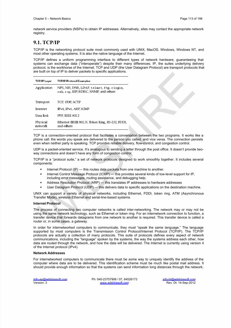
8/22/2019 Solaris%2010%20Handbook.pdf
http://slidepdf.com/reader/full/solaris201020handbookpdf 113/198
Chapter 9 – Network Basics Page 113 of 198
[email protected] Ph: 040-23757906 / 07, 64526173 [email protected] Version: 3 www.wilshiresoft.com Rev. Dt: 14-Sep-2012
network service providers (NSPs) to obtain IP addresses. Alternatively, sites may contact the appropriate networkregistry.
9.1. TCP/IP
TCP/IP is the networking protocol suite most commonly used with UNIX, MacOS, Windows, Windows NT, andmost other operating systems. It is also the native language of the Internet.
TCP/IP defines a uniform programming interface to different types of network hardware, guaranteeing thatsystems can exchange data (“interoperate”) despite their many differences. IP, the suites underlying deliveryprotocol, is the workhorse of the Internet. TCP and UDP (the User Datagram Protocol) are transport protocols thatare built on top of IP to deliver packets to specific applications.
TCP is a connection-oriented protocol that facilitates a conversation between the two programs. It works like aphone call: the words you speak are delivered to the person you called, and vice versa. The connection persistseven when neither party is speaking. TCP provides reliable delivery, flow-control, and congestion control.
UDP is a packet-oriented service. It’s analogous to sending a letter through the post office. It doesn’t provide two -way connections and doesn’t have any form of congestion control.
TCP/IP is a “protocol suite,” a set of network protocols designed to work smoothly together. It includes severalcomponents:
Internet Protocol (IP) --- this routes data packets from one machine to another.
Internet Control Message Protocol (ICMP) --- this provides several kinds of low-level support for IP,including error messages, routing assistance, and debugging help.
Address Resolution Protocol (ARP) --- this translates IP addresses to hardware addresses
User Datagram Protocol (UDP) --- this delivers data to specific applications on the destination machine.
UNIX can support a variety of physical networks, including Ethernet, FDDI, token ring, ATM (AsynchronousTransfer Mode), wireless Ethernet and serial-line-based systems.
Internet Protocol
The process of connecting two computer networks is called inter-networking. The network may or may not beusing the same network technology, such as Ethernet or token ring. For an internetwork connection to function, atransfer device that forwards datagrams from one network to another is required. This transfer device is called arouter or, in some cases, a gateway.
In order for internetworked computers to communicate, they must “speak the same language.” The languagesupported by most computers is the Transmission Control Protocol/Internet Protocol (TCP/IP). The TCP/IPprotocols are actually a collection of many protocols. This suite of protocols defines every aspect of networkcommunications, including the “language” spoken by the systems, the way the systems address each other, howdata are routed through the network, and how the data will be delivered. The Internet is currently using version 4of the Internet protocol (IPv4).
Network Addresses
For internetworked computers to communicate there must be some way to uniquely identify the address of thecomputer where data are to be delivered. This identification scheme must be much like postal mail address. Itshould provide enough information so that the systems can send information long distances through the network,

8/22/2019 Solaris%2010%20Handbook.pdf
http://slidepdf.com/reader/full/solaris201020handbookpdf 114/198
Chapter 9 – Network Basics Page 114 of 198
[email protected] Ph: 040-23757906 / 07, 64526173 [email protected] Version: 3 www.wilshiresoft.com Rev. Dt: 14-Sep-2012
yet have assurance that it will be delivered to the desired destination. As with postal addresses, there must besome sanctioned authority to assign addresses and administer the network.
The TCP/IP protocol defines one portion of the addressing scheme used in most computer networks. The Internetprotocol defines the Internet protocol address (also known as an IP address, or Internet address) scheme. The IPaddress is a unique number assigned to each host on the network.
The vendors of network hardware also provide a portion of the addressing information used on the network. Each
network technology defines a hardware (media) layer addressing scheme unique to that network technology.These hardware-level addresses are referred to as media access controller (MAC) addresses.
Internet Protocol Addresses
Hosts connected to the Internet have a unique Internet Protocol (IP) address. IP addre sses consist of 32-bithexadecimal number, but they are typically represented as a set of four integers separated by periods. Anexample of an Internet address is 192.168.3.1. Each integer in the address must be in the range from 0 to 255.
There are five classes of Internet addresses: Class A, Class B, Class C, Class D, Class E. Class A, B, and Caddresses are used for host addressing. Class D addresses are called multi-cast addresses, and Class Eaddresses are experimental addresses.
Class A Addresses
If the number in the first field of a hosts IP address is in the range 1 to 127, the host is on a Class A network.There are 127 Class A networks. Each Class A network can have up to 16 million hosts. With Class A networks,
the number in the first field identifies the network number, and the remaining three fields identify the host addresson that network.
NOTE: 127.0.0.1 is a reserve IP address called the “loopback address.” All hosts on the Internet use this addressfor their own internal network testing and interprocess communications. Don’t make address assignments of theform 127.x.x.x; nor should you remove the loopback address unless instructed otherwise.
Class B addresses
If the integer in the first field of a hosts IP address is in the range 128 to 191, the host is on a Class B network.There are 16,384 Class B networks with upto 65,000 hosts each. With Class B networks, the integers in the firsttwo fields identify the network number, and the remaining two fields identify the host address on that network. Aninternet protocol address space is shown:
Class 1s
Byte Format # Nets # Hosts per net
Class A
Class B
Class C
0-127 N.H.H.H
128-191 N.N.H.H
192-223 N.N.N.H
127
64
32
15,777,214
65,534
254
*** Network Portion denoted by N and host portion denoted by H
Class C Addresses
If the integer in the first field of a hosts IP address is in the range 192 to 223, the host is on a Class C network.There are 2,097,152 Class C networks with up to 254 hosts each. With Class C networks, the integers in the firstthree fields identify the network address, and the remaining field identifies the host address on that network.
NOTE: The numbers 0 and 255 are reserved for special use in an IP address. The number 0 refers to “thisnetwork.” Number 255, the “broadcast address,” refers to all hosts on a network. For example, the address192.168.0.0. refers to the class C network 192.168. The address 192.168.255.255 is the broadcast address for the 192.168.0.0 network and refers to all hosts on the network.
Public versus Private IP Addresses
There are some address ranges that could be used by sites that don’t connect to the Internet, or by sites thatemployed a firewall to isolate themselves from the Internet.

8/22/2019 Solaris%2010%20Handbook.pdf
http://slidepdf.com/reader/full/solaris201020handbookpdf 115/198
Chapter 9 – Network Basics Page 115 of 198
[email protected] Ph: 040-23757906 / 07, 64526173 [email protected] Version: 3 www.wilshiresoft.com Rev. Dt: 14-Sep-2012
Private IP Address Ranges
Class Starting
Address
Ending Address CIDR Notation
A 10.0.0.0 10.255.255.255 10.0.0.0/8
B 172.16.0.0 172.31.255.255 172.16.0.0./12
C 192.168.0.0 192.168.255.255 192.168.0.0/16
Address Translation
Address translation is a technique that allows a router to transfer private addresses into public addresses. Thisallows sites to assign private addresses internally, yet communicate with other hosts on the Internet using anassigned public IP address.
Some typical applications where address translation is required include connections to cable-modems, DSL, and
other high-speed Internet Service Provider networks. The ISP assigns a single IP address to a customer thatsigns up for cable-modem service. The customer has several computer systems that need to communicate over the Internet. The customer installs Address Translation Software on their router. When an internal host wants tocommunicate with an external host, the translation software goes to work.
The translation software “traps” the outbound packet, and records the destination IP address and servicerequested in a memory-resident table. It then changes the packets “source” address to the address of the localrouter and sends the packet out on the network. When the remote host replies, the packet is sent to the localrouter.
The address translation software intercepts the reply packet, determines where it came from, and looks thisaddress up in the memory-resident table. When it finds a match, the software determines which internal host wascommunicating with this external host, and modifies the packet destination address accordingly. The packet issent along to the internal host using the private address assigned to that host.
Media Access Controller (MAC) Addresses
In addition to IP addresses assigned by the NIC, most networks also employ another form of addressing knownas the hardware or media access controller (MAC) address. Each network interface board is assigned a uniqueMAC address by the manufacturer. In the case of Ethernet interface boards, the MAC address is a 48-bit value.The address is typically written as a series of six 2-byte hexadecimal values separated by colons.
Each network interface manufacturer is assigned a range of addresses it may assign to interface cards. For example, 08:00:20:3f:oi:ee might be the address of a Sun Microsystems Ethernet interface. This address wouldbecome a permanent part of the hardware for a workstation manufactured by the Sun Microsystems. (In a MACaddress, the first 3 bytes are IEEE assigned values and the next 3 bytes are vendor specific values).
Ethernet interfaces know nothing of IP addresses. The IP address is used by a “higher” level of thecommunications software. Instead, when two computers connected to an Ethernet communicate, they do so viaMAC addresses. Data transport over the network media is handled by one systems network hardware. If thedatagram is bound for a foreign network it is sent to the MAC address of the router, which will handle forwardingto the remote network.
Before the datagram is sent to the network interface for delivery, the communications software embeds the IPaddress within the datagram. The routers along the path to the final destination use the IP address to determinethe next “hop” along the path to the final destination. When the datagram arrives at the destination, thecommunications software extracts the IP address to determine what to do with the data.
Internet Protocol Version 6 (IPv6)
IPv4 is running out of address space as a result of the enormous expansion of the Internet in recent years. Inorder to ensure that address space is available in the future, the Internet Engineering Task Force is readying IPv6for deployment. Beginning with Solaris 8, the Solaris OE supports IPv6, and Dual-stack (IPv4/IPv6) protocols.Major differences between IPv4 and IPv6 follow:

8/22/2019 Solaris%2010%20Handbook.pdf
http://slidepdf.com/reader/full/solaris201020handbookpdf 116/198
Chapter 9 – Network Basics Page 116 of 198
[email protected] Ph: 040-23757906 / 07, 64526173 [email protected] Version: 3 www.wilshiresoft.com Rev. Dt: 14-Sep-2012
IPv6 addresses are 128 bits long (as opposed to the IPv4 32-bit addresses). A typical IPv6 address consists of aseries of colon-separated hexadecimal digits. For example, 0xFEDC:BA98:7654:3210:0123:4567:89AB: CDEFmight be a valid IPv6 host address. Provisions have been made to allow IPv4 addresses on an IPv6 network.These addresses will have hexadecimal numbers separated by colons, followed by decimal numbers separatedby periods. Such an address might look like the following:
0000:0000:0000:0000:0000: FFFF: 192.168.33.44
IPv6 implements multicasting to replace the IPv4 broadcast-address scheme. The IPv6 multicast scheme allowsfor several types of “broadcast” addr esses (organizational, Internet-wide, domain-wide, and so forth).
IPv6 doesn’t contain address classes. Some IPv6 address ranges will be reserved for specific services, butotherwise the idea of address classes will vanish.
IPv6 uses classless Internet domain routing (CIDR) algorithms. This new routing algorithm allows for moreefficient router operation in large network environments. Addresses will be assigned regionally to minimize routingtables, and to simplify packet routing. IPv6 can encrypt data on the transport media. IPv4 has no facility thatallows network data to be encrypted.
Ports
IP addresses identify machines, or more precisely, network interfaces on a machine. They are not specificenough to address particular processes or services. TCP and UDP extend IP addresses with a concept known asa “port”. A port is a 16-bit number that supplements an IP address to specify a particular communication channel.Standard UNIX services such as e-mail, FTP, and the remote login server all associate themselve s with “well-known” ports defined in the /etc/services. (UNIX systems restrict access to port numbers under 1024 to root.)
Address Types
Unicast: addresses that refer to a single host.
Multicast: addresses that identify a group of hosts.
Broadcast: addresses that include all hosts on the local network.
9.2. Network Services
Computers are generally networked to take advantage of the information stored on the networks individualsystems. By networking many systems, each of which manages a small portion of the data, the corporation hasaccess to all of the data. This is one of the underlying foundations of distributed computing.
For the systems on the network to take advantage of distributed computing, the network must provide network
services. A few of these services might be IP address to MAC address resolution, host-name-to-IP-addressresolution, network file services, and World Wide Web (WWW) services.
Name Services
Computers are very adept at dealing with numbers. In general, people are not capable of remembering so manynumbers associated with computer networking. People prefer to work with alphabetic names. The IP provides ameans of associating a host name with an IP address. The naming of computers makes it simple for humans toinitiate contact with a remote computer simply by referring to the computer by name.
The Name Server:
Unlike humans, computers refer to remote systems by IP addresses. Name services provide mapping betweenthe hostname humans prefer to use, and the IP addresses computers prefer to use. These name services requirea host (or hosts) connected to the local network to run special name resolution software. These name server hosts have a database containing mappings between hostnames and IP addresses.
Several name services are available under Solaris. Suns Network Information Service (NIS) and the DomainName Service (DNS) are the two name services used most frequently in the Solaris environment. The NIS isdesigned to provide local name service within an organization. The DNS name service is designed to provideInternet-wide name services.
Address Resolution Protocol
Systems connected to an Ethernet prefer to use MAC-level addresses for communications. But how do the hostsdetermine the MAC address of other computers on the network once they know the IP address? The address
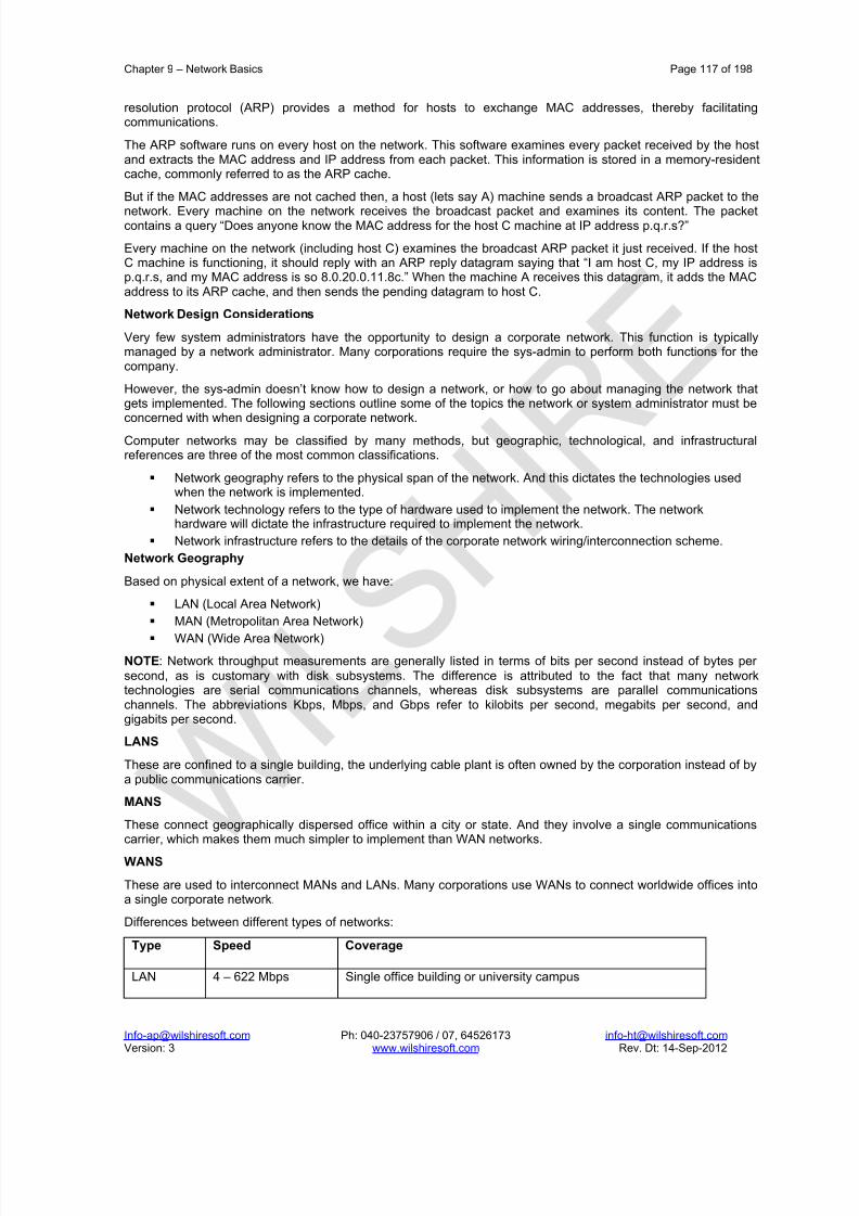
8/22/2019 Solaris%2010%20Handbook.pdf
http://slidepdf.com/reader/full/solaris201020handbookpdf 117/198
Chapter 9 – Network Basics Page 117 of 198
[email protected] Ph: 040-23757906 / 07, 64526173 [email protected] Version: 3 www.wilshiresoft.com Rev. Dt: 14-Sep-2012
resolution protocol (ARP) provides a method for hosts to exchange MAC addresses, thereby facilitatingcommunications.
The ARP software runs on every host on the network. This software examines every packet received by the hostand extracts the MAC address and IP address from each packet. This information is stored in a memory-residentcache, commonly referred to as the ARP cache.
But if the MAC addresses are not cached then, a host (lets say A) machine sends a broadcast ARP packet to the
network. Every machine on the network receives the broadcast packet and examines its content. The packetcontains a query “Does anyone know the MAC address for the host C machine at IP address p.q.r.s?”
Every machine on the network (including host C) examines the broadcast ARP packet it just received. If the hostC machine is functioning, it should reply with an ARP reply datagram saying that “I am host C, my IP address isp.q.r.s, and my MAC address is so 8.0.20.0.11.8c.” When the machine A receives this datagram, it adds the MACaddress to its ARP cache, and then sends the pending datagram to host C.
Network Design Considerations
Very few system administrators have the opportunity to design a corporate network. This function is typicallymanaged by a network administrator. Many corporations require the sys-admin to perform both functions for thecompany.
However, the sys-admin doesn’t know how to design a network, or how to go about managing the network thatgets implemented. The following sections outline some of the topics the network or system administrator must beconcerned with when designing a corporate network.
Computer networks may be classified by many methods, but geographic, technological, and infrastructuralreferences are three of the most common classifications.
Network geography refers to the physical span of the network. And this dictates the technologies usedwhen the network is implemented.
Network technology refers to the type of hardware used to implement the network. The networkhardware will dictate the infrastructure required to implement the network.
Network infrastructure refers to the details of the corporate network wiring/interconnection scheme.
Network Geography
Based on physical extent of a network, we have:
LAN (Local Area Network)
MAN (Metropolitan Area Network)
WAN (Wide Area Network)
NOTE: Network throughput measurements are generally listed in terms of bits per second instead of bytes per second, as is customary with disk subsystems. The difference is attributed to the fact that many networktechnologies are serial communications channels, whereas disk subsystems are parallel communicationschannels. The abbreviations Kbps, Mbps, and Gbps refer to kilobits per second, megabits per second, andgigabits per second.
LANS
These are confined to a single building, the underlying cable plant is often owned by the corporation instead of bya public communications carrier.
MANS
These connect geographically dispersed office within a city or state. And they involve a single communicationscarrier, which makes them much simpler to implement than WAN networks.
WANS
These are used to interconnect MANs and LANs. Many corporations use WANs to connect worldwide offices intoa single corporate network.
Differences between different types of networks:
Type Speed Coverage
LAN 4 – 622 Mbps Single office building or university campus

8/22/2019 Solaris%2010%20Handbook.pdf
http://slidepdf.com/reader/full/solaris201020handbookpdf 118/198
Chapter 9 – Network Basics Page 118 of 198
[email protected] Ph: 040-23757906 / 07, 64526173 [email protected] Version: 3 www.wilshiresoft.com Rev. Dt: 14-Sep-2012
MAN 9.6 Kbps – 45 Mbps Area the size of a city
WAN 56 Kbps – 155 Mbps Span vast geographic areas, like continents
Network Technologies:
We have to study the advantages and disadvantages of all the available technologies (because we have a wide
variety of them available) before implementing the physical network.Ethernet
It is one of the dominant LAN technologies in use today. Ethernet has no pre-arranged order in which hoststransfer data. Any host can transmit onto the network whenever the network is idle. Ethernet is said to be “multipleaccess” (MA). If two hosts transmit simultaneously, however, a data collision occurs. Both hosts will detect thecollision (CD) and stop transmitting. The hosts will then wait a random period before attempting to transmit again.
It is important to note that Ethernet is a best-effort delivery LAN. In other words, it doesnt perform error-correctionor retransmission of lost data when network errors occur due to events such as collisions. Any datagrams thatresult in a collision or arrive at the destination with errors must be retransmitted. On a highly loaded network,retranmission could result in a bottle-neck. It is best suited for LANs whose traffic patterns are data bursts. NFSand NIS are examples of network applications that tend to generate “bursty” network traffic.
Integrated Services Digital Network (ISDN)
ISDN is a multiplexed digital networking scheme for existing telephone facilities (which are mostly analog). Themajor advantage of ISDN is that it can be operated over most existing telephone lines.
Digital Subscriber Loop (DSL)
DSL is a relatively new form of long-haul, high-speed networking. DSL is available in many flavors. Each versionof DSL requires special DSL modem. These modems typically have an Ethernet connection on the local side, anda telephone line interface on the remote side.
Token Ring
Token Ring networks are another widely used local area network technology. A token ring network utilizes aspecial data-structure called a token, which circulates around the ring of connected hosts. Unlike the MA accessscheme of Ethernet, a host on a token ring can transmit data only when it possesses the token. Token ringnetworks operate in receive and transmit modes.
In transmit mode, the interface breaks the ring open. The host sends its data on the output side of the ring, and
then wait until it receives the information back on its input. Once the system receives information it just tranmitted,the token is placed back on the ring to allow other systems permission to transmit information, and the ring isagain closed.
In receive mode, a system copies the data from the input side of the ring to the output side of the ring. If the hostis down and unable to forward the information to the next host on the ring, the network is down. For this reason,many token ring interfaces employ a drop-out mechanism that, when enabled, connects the ring input to the ringoutput. This dropout mechanism is disabled by the network driver software when the system is up and running.However, if the system is not running, the dropout engages and data can get through the interface to the nextsystem on the ring.
Fiber Distributed Data Interconnect
FDDI is a token ring LAN based on fiber optics. FDDI networks are well suited for LANs whose traffic patternsinclude sustained high loads, such as relational database transfers and network tape backups. The FDDIstandards define 2 types of topologies: single attachment stations (SAS) and dual attachment stations (DAS).
Asynchronous Transfer Mode
ATM networks are rapidly becoming a popular networking technology. Because ATM networks are based onpublic telephone carrier standards, the technology may be used for LANs, MANs, and WANs.
ATM, like today’s telephone network, is a hierarchal standard that employs a connection-oriented protocol. For two hosts to communicate, one must “place a call” to the other. When the conversation is over, the connection isbroken. Most ATM networks are implemented over fiber optic media, although recent standards also defineconnections over twisted-pair copper cable plants.
Network Ethernet ISDN DSL FDDI ATM

8/22/2019 Solaris%2010%20Handbook.pdf
http://slidepdf.com/reader/full/solaris201020handbookpdf 119/198
Chapter 9 – Network Basics Page 119 of 198
[email protected] Ph: 040-23757906 / 07, 64526173 [email protected] Version: 3 www.wilshiresoft.com Rev. Dt: 14-Sep-2012
Technology
Speed 100Mbps 128Kbps 45Mbps 100Mbps 1 Gbps
**The maximum speeds which they are supporting is listed.
Network Infrastructures
The infrastructure of a network includes the cable plant required to tie the hosts together, the physical topology of the wire within the buildings, the type of electronics employed in the network, and the bandwidth requirements of the hosts connected to the network.
Bandwidth Requirements
(These are generic guidelines; configurations may vary depending on requirements)
A good rule of thumb for network design is to provide a hierarchal network structure. At the top (root) of thehierarchy is the corporate backbone. Systems connected to this network typically provide corporation-wideservices such as routing, name service, and firewall protection. These services are typically in high demand, andtherefore require the most network bandwidth. Connections at this level of the network should be the fastestavailable, typically 100 Mbits/second or faster.
One layer down from the root of the network is the portion of the network that provides connectivity to the other hosts on the network services. A few examples of the services at this level include network file system servers, e-mail servers, application servers, and license servers. These services, although still in high demand, are typicallyless bandwidth intensive than the top-level network services. Connections at this level are typically moderatespeed connections (100 Mbits/second). At the bottom layer of the network are individual workstations. Thesemachines typically require the least bandwidth, and therefore get the slowest links to the network, typically 10Mbits/second.
Network Electronics
The next step in the network design is to determine the type of electronics required to implement the network. For example, should the low-speed connections be implemented via network hubs, network switches, or routers?Should the high-speed connections be implemented via FDDI, ATM, or Fast Ethernet? Should hosts be used asrouters, or should dedicated routers be used to handle the routing of network traffic?
Network Implementation Issues
After deciding about the physical implementation of the network – the other issues which crop up are:
Determining if the network media is overloaded.
Minimizing media overload conditions.
Decide routes for the packets.
NETMASKS
These provide a method for segmenting large networks into smaller networks. For example, a Class A networkcould be segmented into several Class B and Class C networks. The “boundaries” of each network can be defined by providing a “mask” value, which is logically ANDed with the IP address for a host.
Each bit in the netmask with a value of 1 represents a bit of the network address. Netmask bits with zero (0)values represent bits used for the host address. For example, a netmask of 255.255.255.224 provides for 27 bitsof network address and 5 bits of host address. Such a netmask would provide a network of 30 hosts.
A Class B network number uses 16-bits for the network address, and 16 bits for the host address on the network.What would happen if a Class B network was treated as a group of Class C networks instead? This would allow
the site to have 254 individual networks instead of a single network. The implications of this segmentation aresummarized in the following:
External routers still route packets to the host listed as the gateway for the Class B network. This means that thegateway machine will be required to forward all incoming traffic to other hosts on the internal network.
Internal routers will be required to keep track of how to forward packets to internal network segments. This impliesthe existence of a name server, and the use of an internal routing protocol within the internal network. This alsosuggests that the assignment of IP addresses should be handled geographically such that the routing tableswould be minimized within the network.
Subnets

8/22/2019 Solaris%2010%20Handbook.pdf
http://slidepdf.com/reader/full/solaris201020handbookpdf 120/198
Chapter 9 – Network Basics Page 120 of 198
[email protected] Ph: 040-23757906 / 07, 64526173 [email protected] Version: 3 www.wilshiresoft.com Rev. Dt: 14-Sep-2012
All IP address classes allow more than 250 hosts to be connected to a network. In the real world, this is aproblem. Ethernet is the dominant network technology in use in private sector and campus networks. Due to theshared bandwidth design of Ethernet, more hosts on a network means less bandwidth is available to each host.How can this bandwidth problem be overcome?
One method of partitioning the network traffic is through a process called subnetting the network. Someorganizations place each department on a separate subnet. Others use the geographic location of a host (such asthe floor of an office building) as the subnet boundary. By segmenting the network media into logical entities, the
network traffic is also segmented over many networks, an example of which is shown:

8/22/2019 Solaris%2010%20Handbook.pdf
http://slidepdf.com/reader/full/solaris201020handbookpdf 121/198
Chapter 9 – Network Basics Page 121 of 198
[email protected] Ph: 040-23757906 / 07, 64526173 [email protected] Version: 3 www.wilshiresoft.com Rev. Dt: 14-Sep-2012
Corporate backbone network
192.168.4.0
192.168.1.0 192.168.2.0
1st floor subnet 2nd
floor subnet
192.168.3.0
3rd
floor subnet
For example, the machines on the 3rd
floor no longer have to contend with the machines on the 2nd
floor for anetwork access. Because the “floor” subnets are tied together by a router (or gateway), the machines may stillcommunicate when required, but otherwise the third floor machines dont “see” traffic bound for the second floor
machines. But should the sub-nets be incorporated into a network, and how are subnets implemented?When to Subnet?
There are no absolute formulas for determining when or how to subnet a network. The network topology, the LANtechnology being implemented, network bandwidth, and host applications all affect a networks performance.However subnetting should be considered if one or more of the following conditions exist.
There are more than 20 hosts on the network.
Network applications slow down as users begin accessing the network.
A high percentage of packets on the network are involved in collisions.
Obtaining accurate network load statistics requires sophisticated (and expensive) network analysis equipment.However, network load can be estimated by calculating the network interface collision rate on each host. This canbe done using the netstat – i – n command.
Using the information from thenetstat
commands output, divide the total collisions by the output packets, and
then multiply the result by 100. To obtain a rough idea of the network collision rate, collect netstat – i statistics
for all hosts on the network and average them. Collision rates under 2% are generally considered acceptable.Rates of 2% to 8% indicate a loaded network. Rates over 8% indicate a heavily loaded network that should beconsidered for subnettting.
From a troubleshooting perspective, subnetting allows administrators to isolate (disconnect) pieces (subnets) of anetwork when trying to resolve network problems. By isolating a subnet, it is often easier to determine the sourceof a network problem. Most routers, gateways, hubs, and multi-port transceivers have a switch allowing them tooperate in standalone mode. If the switch is set to local mode, the subnet is disconnected from the rest of thenetwork. With the switch set to remote mode, the subnet is connected to the rest of the network.
Routing Concerns
All networks require some form of packet routing to ensure that packets get from one host to another. On a simple
(single wire) network, the routing is also simple: a source host sends a packet out onto the media, and thedestination host picks it up. On a multi-tiered or subnetted network, routing becomes much more difficult. On theinternet, routing can become a nightmare.
Routing Overview
Network routing is an iterative process. Consider the problem – a visitor to a large city would have trying to locatean office in a building in a city that she is unfamiliar with. Generally this problem is broken down into a sequenceof smaller problems, as summarized in the following:
Determine how to get to the destination city.
Determine which quadrant of the city contains the desired street.
IP ROUTER

8/22/2019 Solaris%2010%20Handbook.pdf
http://slidepdf.com/reader/full/solaris201020handbookpdf 122/198
Chapter 9 – Network Basics Page 122 of 198
[email protected] Ph: 040-23757906 / 07, 64526173 [email protected] Version: 3 www.wilshiresoft.com Rev. Dt: 14-Sep-2012
Determine where the desired building is located on the street.
Determine where the office is located in the building.
The first 2 steps in this process are roughly equivalent to external routing. The last two steps are roughlyequivalent to internal routing.
In general, an organization should advertise a single routing address. Generally, this address is the networkportion of the IP address registered to the organization. Routers on the Internet search the network potion of the
IP address, and then forward packets toward the destination based on this information. This process is known asexternal routing.
Once the packet gets to the corporation, the internal router search the host portion of the address (and anyapplicable network mask) to determine how to deliver the packet to its final destination. This portion of the routingprocess is known as internal routing.
The following discussion of routing is organized into three areas. First, internal routing refers to the routingalgorithm used within a corporation’s network. External routing refers to the routing algorithm used to allow thecorporate network hosts to communicate with the outside world (e.g., other hosts on the Internet). Finallysupernets, or classless inter-domain routing (CIDR) blocks are discussed.
External Routing
This allows packets from the outside world to be delivered to the LAN, and vice-versa. Several external routingprotocols are available for use on the Internet.
External routing typically involves determining the next hop along the path to the final destination. A distant router that wants to deliver a datagram to a host on the LAN doesnt need to know the exact set of gateways required toget the packet to the final destination. Instead, the external router just needs to know the address of another router which is one step closer to the final destination.
External routers periodically exchange routing information with their “peers.” Each router knows the specifics of packet delivery within their local network. By exchanging information with other routers they build a rouitng tablewhich contains information about how to get datagrams to other networks. When the routers exchange routinginformation they are “advertising” routes to destinations. In other words, the information exchanged between routers includes an implied promise that the router knows how to get datagrams delivered to specific destinations.
Internal Routing
One host or router on the LAN must be configured to run one of the external routing protocols. This router/hostwill receive all (externally sourced) datagrams bound for hosts on the LAN. The router/host will have to makeinternal routing decisions in order to facilitate the delivery of the data to the local destination host. Likewise,
internal network traffic must be routed to destinations on the LAN. Therefore, the router which provides externalrouting must also know how to perform internal routing.
Internal routing may be handled in two ways. First, the network manager may tell each host to send all packets toa central router (or host) for delivery (static routing). Alternatively, the individual hosts may be allowed todetermine how to get packet from point A to point B (dynamic routing). Each routing algorithm has strengths andweaknesses.
Supernets
The opposite of subnetting is referred to as “supernetting.” Because the number of available network addresses isdwindling under IPv4, some entities end up with multiple Class C network numbers when they really need a ClassB network number. The process of supernetting allows the organization to maintain a single gateway to theoutside world by combining the Class C network addresses into single addressable supernetwork. Thesesupernetworks are also known as classless inter-domain routing (CIDR) blocks.
Assume that an organization with 400 hosts wanted to connect to the Internet, and applied for an IP address. TheInternet service provider may not have a free block of contiguous addresses to assign to the organization. TheISP could assign two Class C network numbers to the organization, and offer to provide the external routing for the organization by advertising a single supernet address to the rest of the network.
For example, suppose the organization was assigned the network number 192.168.4.0 and 192.168.5.0.Expressing these two addresses as binary numbers shows that they share a common 22-bit prefix. The ISP couldadvertise a route to the network 192.168.4/22. This tells the rest of the world that the first 22 bits of the addressare used as the network address, with the remaining 10 bits used as the host address.

8/22/2019 Solaris%2010%20Handbook.pdf
http://slidepdf.com/reader/full/solaris201020handbookpdf 123/198
Chapter 9 – Network Basics Page 123 of 198
[email protected] Ph: 040-23757906 / 07, 64526173 [email protected] Version: 3 www.wilshiresoft.com Rev. Dt: 14-Sep-2012
The external routers know to forward all datagram’s bound for hosts on the corporations two networks to the ISPsrouter based on this information. The ISPs router forwards the datagram’s to the corporate router f or final delivery. An example of supernet routing is shown in the following illustration:
192.168.7.0 = 11000000 10101000 00000111 00000000
192.168.6.0 = 11000000 10101000 00000110 00000000
First 23 bits of both networks are the same
Netmask = 11111111 11111111 11111100 00000000
Advertise = 11000000 10101000 00000110 00000000
192 168 6 /23
Network Monitoring and Troubleshooting
One method of troubleshooting is to use monitoring tools that determine how the network is being used. Another method is to watch the console error messages generated by the machines connected to the network.
Console Error Messages
Error messages that Solaris sends to the system console may provide a lot of information about the health of thesystem and the network.
Simple Network Management Protocol (SNMP)SNMP operates in a client/server mode. One machine on the network is designated as the SNMP networkmonitor station. It is configured to poll hosts on the local network in order to collect data into a central repository.The data may be made available to other packages in order to implement alarms, generate graphs of networkutilization, and other off-line processing.
The other hosts on the network are configured as SNMP clients. These hosts run a process that watches for polling requests from the network management station. When such a request is received, the SNMP agent codecollects the data from the workstations kernel and forwards it to the management station.
Network Troubleshooting Commands
snoop Utility
The common uses of snoop are:
Monitoring traffic between two hosts Monitoring traffic using a particular protocol
Monitoring traffic containing specific data
Monitoring a network to determine which host is creating the most network traffic
ping Utility
The command name stands for “packet Internet groper,” and is used to test reachability of hosts by sending anICMP echo request and waiting for a reply. If there is no reply then, there can be other causes like:
Faulty physical connection.
Faulty host interface
Corrupted /etc/inet/hosts file
Missing or corrupted /etc/hostname.hme0 file
Interface is turned off
Host is down.
Rebooting the non-responsive host solves most of the problems most of the times.
traceroute Utility
This utility traces the route from point A to point B. It is useful when trying to determine why two hosts cannotcommunicate. It basically prints an informational message about each “hop” along the route from the local host tothe remote host. Routing loops and inoperative hosts are very easy to spot in the traceroute output.

8/22/2019 Solaris%2010%20Handbook.pdf
http://slidepdf.com/reader/full/solaris201020handbookpdf 124/198
Chapter 10 – Swap, Core & Crash Files Page 124 of 194
[email protected] Ph: 040-23757906 / 07, 64526173 [email protected] Version: 3 www.wilshiresoft.com Rev. Dt: 14-Sep-2012
10. Swap, Core & Crash Files
10.1. Virtual Memory Concepts
The virtual memory system can be considered the core of a Solaris system and the implementation of Solarisvirtual memory affects just about every other sub-system in the operating system.
The need of Virtual memory
It presents a simple memory programming model to applications so that application developers need not knowhow the underlying memory hardware is arranged. It gives us a programming model with a larger memory sizethan available physical storage (e.g., RAM) and enables us to use slower but larger seconda ry storage (e.g., disk)as a backing store to hold the pieces of memory that dont fit in physical memory.
The VM system transparently manages the virtual storage between RAM and secondary storage. Because RAMis significantly faster than disk, (100 ns versus 10 ms), the job of the VM system is to keep the most frequentlyreferenced portions of memory in the faster primary storage. In the event of RAM shortage, the VM system isrequired to free RAM by transferring infrequently used memory to the secondary storage. By doing so, the VMsystem optimizes performance and removes the need for users to manage the allocation of their own memory.
Physical memory (RAM) is divided into fixed-size pieces called pages. The size of a page can vary acrossdifferent platforms. The process of migrating the physical page contents to the “backing store” is known as apage-out. Reading back the contents from the backing store i.e. migrating in is called a page-in.
We have more virtual address space than physical address space because the operating system can overflowmemory onto a slower medium, like a disk. The slower medium in UNIX is called swap space. If there is ashortage of memory, then all of the pages in memory of the least-active process are swapped out to the swapdevice, freeing memory for other processes. This is how swapping of memory between primary and secondarystorage helps in optimizing performance.
Swap Space
The Solaris OS uses some disk slices for temporary storage rather than for file systems. These slices are calledswap slices, or swap space. Swap space is used for virtual memory storage areas when the system does nothave enough physical memory to handle current processes. Since many applications rely on swap space, youshould know how to plan for, monitor, and add more swap space, when needed.
Swap Space and Virtual Memory
The virtual memory system maps physical copies of files on disk to virtual addresses in memory. Physicalmemory pages that contain the data for these mappings can be backed by regular files in the file system, or byswap space. If the memory is backed by swap space it is referred to as anonymous memory because no identityis assigned to the disk space that is backing the memory.
The Solaris OS uses the concept of virtual swap space, a layer between anonymous memory pages and thephysical storage (or disk-backed swap space) that actually back these pages. A system’s virtual swap space isequal to the sum of all its physical (disk-backed) swap space plus a portion of the currently available physicalmemory.
Virtual swap space has these advantages:
The need for large amounts of physical swap space is reduced because virtual swap space does not necessarilycorrespond to physical (disk) storage.
A pseudo file system called SWAPFS provides addresses for anonymous memory pages. Because SWAPFScontrols the allocation of memory pages, it has greater flexibility in deciding what happens to a page. For
example, SWAPFS might change the page’s requirements for disk-backed swap storage.
Swap Space and the TMPFS File System
The TMPFS file system is activated automatically in the Solaris environment by an entry in the /etc/vfstab file.The TMPFS file system stores files and their associated information in memory (in the /tmp directory) rather than
on disk, which speeds access to those files. This feature results in a major performance enhancement for applications such as compilers and DBMS products that use /tmp heavily.
The TMPFS file system allocates space in the /tmp directory from the system’s swap resources. This feature
means that as you use up space in the /tmp directory, you are also using up swap space. So, if your applications

8/22/2019 Solaris%2010%20Handbook.pdf
http://slidepdf.com/reader/full/solaris201020handbookpdf 125/198
Chapter 10 – Swap, Core & Crash Files Page 125 of 194
[email protected] Ph: 040-23757906 / 07, 64526173 [email protected] Version: 3 www.wilshiresoft.com Rev. Dt: 14-Sep-2012
use the /tmp directory heavily and you do not monitor swap space usage, your system could run out of swap
space.
Do use the following if you want to use TMPFS, but your swap resources are limited:
1. Mount the TMPFS file system with the size option (-o size) to control how much swap resourcesTMPFS can use.
2. Use your compiler’s TMPDIR environment variable to point to another larger directory.
Swap Space as a Dump Device
A dump device is usually disk space that is reserved to store system crash dump information. By default, asystem’s dump device is configured to be a swap slice. If possible, you should configure an alternate disk partitionas a dedicated dump device instead to provide increased reliability for crash dumps and faster reboot time after asystem failure. You can configure a dedicated dump device by using the dumpadm command.
10.2. Configuring Swap
How Do I Know If I Need More Swap Space?
Use the swap -l command to determine if your system needs more swap space. When a sys tem’s swap space
is at 100% allocation, an application’s memory pages become temporarily locked. Application errors might notoccur, but system performance will likely suffer.
Planning for Swap Space
The most important factors in determining swap space size are the requirements of the system’s softwareapplications. For example, large applications such as computer-aided design simulators, database managementproducts, transaction monitors, and geologic analysis systems can consume as much as 200 –1000 Mbytes of swap space. Consult your application vendors for swap space requirements for their applications.
Adding More Swap Space
As system configurations change and new software packages are installed, you might need to add more swapspace. The easiest way to add more swap space is to use the mkfile and swap commands to designate a part of an existing UFS or NFS file system as a supplementary swap area.
10.3. Core Files and Crash Dumps
10.3.1. Core Files
Core files are generated when a process or application terminates abnormally. Core files are managed with thecoreadm command. When a process terminates abnormally, it produces a core file in the current directory by
default. If the global core file path is enabled, each abnormally terminating process might produce two files, one inthe current working directory, and one in the global core file location. By default, a setuid process does notproduce core files using either the global or per-process path.
Configurable Core File Paths:
Two new configurable core file paths that can be enabled or disabled independently of each other are:
1. A per-process core file path, which defaults to core and is enabled by default. If enabled, the per-process
core file path causes a core file to be produced when the process terminates abnormally. The per-
8/22/2019 Solaris%2010%20Handbook.pdf
http://slidepdf.com/reader/full/solaris201020handbookpdf 126/198
Chapter 10 – Swap, Core & Crash Files Page 126 of 194
[email protected] Ph: 040-23757906 / 07, 64526173 [email protected] Version: 3 www.wilshiresoft.com Rev. Dt: 14-Sep-2012
process path is inherited by a new process from its parent process. When generated, a per-process corefile is owned by the owner of process with read/write permissions for the owner. Only the owning user canview this file.
2. A global core file path, which defaults to core and is disabled by default. If enabled, an additionalcore file with the same content as the per-process core file is produced by using the global core file path.When generated, a global core file is owned by superuser with read/write permissions for superuser only.Non-privileged users cannot view this file.
Specify Core File Content with coreadm
The coreadm command lets you specify which parts of a process are present in the core file during a crash. You
can see the system’s configuration by running coreadm with no arguments. You can specify the global core filecontent and the default per-process core file content by using the -G and -I options respectively. Each optionrequires a set of content specifier tokens. You can also set the core file content for individual processes by usingthe -P option. Core dumps that correspond to the global settings no longer honor the per-process, core file-sizeresource control. The -i and -I options to the coreadm command now apply to all processes whose core filesettings are using the system-wide default. Use the -p and -P options to override the default.
gcore Core File Content
The gcore utility creates core files from a running process without damaging that process. The gcore utility nowsupports variable core file content. Use the -c option to specify the content or the -p or -g options to force
gcore to use the coreadm settings.
mdb Supports Text and Symbol Tables in Core Files
Text is now in core files by default. Also, symbol tables can now be in core files by default. The mdb utility has
been updated to support this new core file data. This support means you can now debug your old core file withoutneeding the original binary or the libraries that are linked to that file.
Displaying the Current Core Dump Configuration
$ coreadm
Setting a Core File Name Pattern
Set a per-process file name pattern.
$ coreadm -p $HOME/corefiles/%f.%p $$
Set a global file name pattern.# coreadm -g /var/corefiles/%f.%p
Enabling a Per-Process Core File Path
# coreadm -e process
Display the current process core file path to verify the configuration.
$ coreadm $$
1180: /home/kryten/corefiles/%f.%p
Enabling a Global Core File Path
# coreadm -e global -g /var/core/core.%f.%p
Display the current process core file path to verify the configuration.
# coreadm
Examining Core Files
Some of the proc tools have been enhanced to examine process core files as well as live processes. The proctools are utilities that can manipulate features of the /proc file system. The /usr/proc/bin/pstack, pmap,
pldd, pflags, and pcred tools can now be applied to core files by specifying the name of the core file on the
command line, similar to the way you specify a process ID to these commands.
$ ./a.out
Segmentation Fault(coredump)

8/22/2019 Solaris%2010%20Handbook.pdf
http://slidepdf.com/reader/full/solaris201020handbookpdf 127/198
Chapter 10 – Swap, Core & Crash Files Page 127 of 194
[email protected] Ph: 040-23757906 / 07, 64526173 [email protected] Version: 3 www.wilshiresoft.com Rev. Dt: 14-Sep-2012
$ /usr/proc/bin/pstack ./core
core ’./core’ of 19305: ./a.out
000108c4 main (1, ffbef5cc, ffbef5d4, 20800, 0, 0) + 1c
00010880 _start (0, 0, 0, 0, 0, 0) + b8
10.3.2. Crash Dumps
System Crashes
System crashes can occur due to hardware malfunctions, I/O problems, and software errors. If the systemcrashes, it will display an error message on the console, and then write a copy of its physical memory to the dumpdevice. The system will then reboot automatically. When the system reboots, the savecore command isexecuted to retrieve the data from the dump device and write the saved crash dump to your savecore directory.
The saved crash dump files provide invaluable information to your support provider to aid in diagnosing theproblem.
System Crash Dump Files
The savecore command runs automatically after a system crash to retrieve the crash dump information from thedump device and writes a pair of files called unix.X and vmcore.X , where X identifies the dump sequence
number. Together, these files represent the saved system crash dump information. Crash dump files aresometimes confused with core files, which are images of user applications that are written when the application
terminates abnormally. Crash dump files are saved in a predetermined directory, which by default, is/var/crash/hostname. System crash information is managed with the dumpadm command.
Additionally, crash dumps saved by savecore can be useful to send to a customer service representative for
analysis of why the system is crashing.
The dumpadm Command
Use the dumpadm command to manage system crash dump information in the Solaris Operating System.
1. The dumpadm command enables you to configure crash dumps of the operating system. The dumpadm configuration parameters include the dump content, dump device, and the directory in which crash dumpfiles are saved.
2. Dump data is stored in compressed format on the dump device. Kernel crash dump images can be as bigas 4 Gbytes or more. Compressing the data means faster dumping and less disk space needed for thedump device.
3. Saving crash dump files is run in the background when a dedicated dump device, not the swap area, ispart of the dump configuration. This means a booting system does not wait for the savecore command
to complete before going to the next step. On large memory systems, the system can be available beforesavecore completes.
4. System crash dump files, generated by the savecore command, are saved by default.
5. The savecore -L command is a new feature, which enables you to get a crash dump of the live running
Solaris OS. This command is intended for troubleshooting a running system by taking a snapshot of memory during some bad state, such as a transient performance problem or service outage. If the systemis up and you can still run some commands, you can execute the savecore – L command to save a
snapshot of the system to the dump device, and then immediately write out the crash dump files to your savecore directory. Because the system is still running, you can only use the savecore -L command if you have configured a dedicated dump device.
How the dumpadm Command Works
During system startup, the dumpadm command is invoked by the svc:/system/dumpadm:default service toconfigure crash dumps parameters based on information in the /etc/dumpadm.conf file. Specifically, dumpadm initializes the dump device and the dump content through the /dev/dump interface. After the dump configuration
is complete, the savecore script looks for the location of the crash dump file directory by parsing the content of /etc/dumpadm.conf file. Then, savecore is invoked to check for crash dumps and check the content of the
minfree file in the crash dump directory.
Displaying the Current Crash Dump Configuration
# dumpadm

8/22/2019 Solaris%2010%20Handbook.pdf
http://slidepdf.com/reader/full/solaris201020handbookpdf 128/198
Chapter 10 – Swap, Core & Crash Files Page 128 of 194
[email protected] Ph: 040-23757906 / 07, 64526173 [email protected] Version: 3 www.wilshiresoft.com Rev. Dt: 14-Sep-2012
Dump content: kernel pages
Dump device: /dev/dsk/c0t3d0s1 (swap)
Savecore directory: /var/crash/venus
Savecore enabled: yes
The preceding example output means:
The dump content is kernel memory pages.
1. Kernel memory will be dumped on a swap device, /dev/dsk/c0t3d0s1. You can identify all your swapareas with the swap -l command.
2. System crash dump files will be written in the /var/crash/venus directory.
3. Saving crash dump files is enabled.
Modifying a Crash Dump Configuration
In this example, all of memory is dumped to the dedicated dump device, /dev/dsk/c0t1d0s1, and the
minimum free space that must be available after the crash dump files are saved is 10% of the file system space.
# dumpadm
Dump content: kernel pages
Dump device: /dev/dsk/c0t3d0s1 (swap)
Savecore directory: /var/crash/plutoSavecore enabled: yes
# dumpadm -c all -d /dev/dsk/c0t1d0s1 -m 10%
Dump content: all pages
Dump device: /dev/dsk/c0t1d0s1 (dedicated)
Savecore directory: /var/crash/pluto (minfree = 77071KB)
Savecore enabled: yes
Examining a Crash Dump
The following example shows sample output from the mdb utility, which includes system information andidentifies the tunables that are set in this system’s /etc/system file.
# /usr/bin/mdb -k unix.0
Loading modules: [ unix krtld genunix ip nfs ipc ptm ]
> ::statusdebugging crash dump /dev/mem (64-bit) from ozlo
operating system: 5.10 Generic (sun4u)
> ::system
set ufs_ninode=0x9c40 [0t40000]
set ncsize=0x4e20 [0t20000]
set pt_cnt=0x400 [0t1024]
Disabling or Enabling Saving Crash Dumps
This example illustrates how to disable the saving of crash dumps on your system.
# dumpadm -n
Dump content: all pages
Dump device: /dev/dsk/c0t1d0s1 (dedicated)
Savecore directory: /var/crash/pluto (minfree = 77071KB)Savecore enabled: no
Enabling the Saving of Crash Dumps
This example illustrates how to enable the saving of crash dump on your system.
# dumpadm -y
Dump content: all pages
Dump device: /dev/dsk/c0t1d0s1 (dedicated)
Savecore directory: /var/crash/pluto (minfree = 77071KB)

8/22/2019 Solaris%2010%20Handbook.pdf
http://slidepdf.com/reader/full/solaris201020handbookpdf 129/198
Chapter 10 – Swap, Core & Crash Files Page 129 of 194
[email protected] Ph: 040-23757906 / 07, 64526173 [email protected] Version: 3 www.wilshiresoft.com Rev. Dt: 14-Sep-2012
Savecore enabled: yes

8/22/2019 Solaris%2010%20Handbook.pdf
http://slidepdf.com/reader/full/solaris201020handbookpdf 130/198
Chapter 11 – Network File Systems Page 130 of 198
[email protected] Ph: 040-23757906 / 07, 64526173 [email protected] Version: 3 www.wilshiresoft.com Rev. Dt: 14-Sep-2012
11. Network File SystemsWe studied the different types of filesystems supported by the Solaris OE. In that flow, we studied about theNetwork File System (NFS). It was developed by Sun Microsystems in the mid-1980s. It is a standard feature onmost UNIX operating systems, including VMS, MS-DOS/Windows, and Macintosh (MacOS). It is a publishedstandard that allows file sharing among hosts over a network.
NOTE: In the Solaris 10 release, NFS version 4 is the default. NFS service is managed by the ServiceManagement Facility.
The objects that can be shared with the NFS service include any whole or partial directory tree or a filehierarchy—including a single file. A computer cannot share a file hierarchy that overlaps a file hierarchy that isalready shared. Peripheral devices such as modems and printers cannot be shared. The NFS service has thefollowing benefits:
Enables multiple computers to use the same files so that everyone on the network can access the samedata
Reduces storage costs by having computers share applications instead of needing local disk space for each user application
Provides data consistency and reliability because all users can read the same set of files
Makes mounting of file systems transparent to users
Makes accessing of remote files transparent to users
Supports heterogeneous environments
Reduces system administration overhead
11.1. NFS terminology
A host that shares file systems via NFS is called a NFS server. A host that mounts file systems from other hosts iscalled a client. A host can be both client and server. Networks on which there are servers and clients are calledclient-server networks. Networks where hosts are both client and server to each other are often called peer-to-peer networks. Most large networks have a mix of clients, servers and peers.
A file system, which is often offered for mounting by a server via NFS, is said to be shared. This term comes fromthe share command used to offer file systems for mounting. Similar to other file system types, a remote filesystem is mounted on a client using the mount command. The shared portion of the servers file systems can bemounted in the same location, or in a different location in the UNIX file tree, on the client.
11.2. Remote Procedure Call (RPC)
A key to NFS operation is its use of a protocol called remote procedure call (RPC). The RPC protocol wasdeveloped by Sun Microsystems in the mid-1980s along with NFS. A procedure call is a method by which aprogram makes use of a sub-routine. The RPC mechanism extends the procedure call to span the network,allowing the procedure call to be performed on a remote machine. In NFS, this is used to access files on remotemachines by extending basic file operations such as read and write across the network.
How RPC Works
To understand the purpose of RPC, first consider how the computer system interacts with the files stored on itslocal disk. When Solaris program is read into memory from disk, or a file is read or written, system calls are madeto the read or write procedures in the SunOS kernel. As a result, data is read from or written to the file system.
When a file is read from or written to an NFS file system on a network, the read or write calls are made over the
network via RPC. The RPC mechanism performs the read or writes operation needed on the servers file systemon behalf of the client. If the NFS client or server is a different type of host or operating system, such as VMS or aPC running Windows, the RPC mechanism also handles data conversion.
The result is that the information returned by the read or write call appears to be the same as if the read or writehad occurred on a local disk. Although this appears complex, it all occurs at the filesystem level and requires nochanges to normal operations on files or internal programs. As far as the programs that need to read and write thefiles are concerned, NFS is just another file system. The transparent nature of NFS is one of its best features.

8/22/2019 Solaris%2010%20Handbook.pdf
http://slidepdf.com/reader/full/solaris201020handbookpdf 131/198
Chapter 11 – Network File Systems Page 131 of 198
[email protected] Ph: 040-23757906 / 07, 64526173 [email protected] Version: 3 www.wilshiresoft.com Rev. Dt: 14-Sep-2012
NFS FILES
11.3. NFS Commands
automount
This command installs autofs mount points and associates the information in the automaster files with each mountpoint. The syntax of the command is as follows:
automount [ -t duration ] [ -v ]
-t duration sets the time, in seconds, that a file system is to remain mounted, and – v selects the verbose mode.Running this command in the verbose mode allows for easier troubleshooting.
clear_locks
This command enables you to remove all file, record, and share locks for an NFS client. You must be root to runthis command. From an NFS server, you can clear the locks for a specific client. From an NFS client, you canclear locks for that client on a specific server. The following example would clear the locks for the NFS client thatis named tulip on the current system.
# clear_locks tulip
Using the -s option enables you to specify which NFS host to clear the locks from. You must run this option fromthe NFS client, which created the locks. In this situation, the locks from the client would be removed from the NFSserver that is named bee.

8/22/2019 Solaris%2010%20Handbook.pdf
http://slidepdf.com/reader/full/solaris201020handbookpdf 132/198
Chapter 11 – Network File Systems Page 132 of 198
[email protected] Ph: 040-23757906 / 07, 64526173 [email protected] Version: 3 www.wilshiresoft.com Rev. Dt: 14-Sep-2012
# clear_locks -s bee
Caution – This command should only be run when a client crashes and cannot clear its locks. To avoid datacorruption problems, do not clear locks for an active client.
mount
With this command, you can attach a named file system, either local or remote, to a specified mount point. Usedwithout arguments, mount displays a list of file systems that are currently mounted on your computer.
mountall
Use this command to mount all file systems or a specific group of file systems that are listed in a file-system table.The command provides a way of doing the following:
1. Selecting the file-system type to be accessed with the -F FSType option
2. Selecting all the remote file systems that are listed in a file-system table with the – r option
3. Selecting all the local file systems with the -l option
setmnt
This command creates an /etc/mnttab table. The mount and umount commands consult the table. Generally,
you do not have to run this command manually, as this command runs automatically when a system is booted.
share
With this command, you can make a local file system on an NFS server available for mounting. You can also usethe share command to display a list of the file systems on your system that are currently shared. The NFS server must be running for the share command to work. The NFS server software is started automatically during boot if an entry is in /etc/dfs/dfstab . The command does not report an error if the NFS server software is not
running, so you must verify that the software is running.
shareall
This command allows for multiple file systems to be shared. When used with no options, the command shares allentries in /etc/dfs/dfstab . You can include a file name to specify the name of a file that lists share commandlines. If you do not include a file name, /etc/dfs/dfstab is checked. If you use a “-” to replace the file name,
you can type share commands from standard input.
showmount
This command displays one of the following:
All clients that have remotely mounted file systems that are shared from an NFS server
Only the file systems that are mounted by clients
The shared file systems with the client access information
Note – The showmount command only shows NFS version 2 and version 3 exports. This command does notshow NFS version 4 exports.
umount
This command enables you to remove a remote file system that is currently mounted. The umount commandsupports the -V option to allow for testing. You might also use the -a option to umount several file systems at one
time. If mount_points are included with the -a option, those file systems are unmounted. If no mount points areincluded, an attempt is made to unmount all file systems that are listed in /etc/mnttab except for the “required”file systems, such as /, /usr, /var, /proc, /dev/fd, and /tmp . Because the file system is alreadymounted and should have an entry in /etc/mnttab , you do not need to include a flag for the file-system type.
The -f option forces a busy file system to be unmounted. You can use this option to unhang a client that is hungwhile trying to mount an unmountable file system.
Caution – By forcing an unmount of a file system; you can cause data loss if files are being written to.
umountall
Use this command to unmount a group of file systems. The -k option runs the fuser -k mount_point command to kill any processes that are associated with the mount_point. The -s option indicates that unmount isnot to be performed in parallel. -l specifies that only local file systems are to be used, and -r specifies that only

8/22/2019 Solaris%2010%20Handbook.pdf
http://slidepdf.com/reader/full/solaris201020handbookpdf 133/198
Chapter 11 – Network File Systems Page 133 of 198
[email protected] Ph: 040-23757906 / 07, 64526173 [email protected] Version: 3 www.wilshiresoft.com Rev. Dt: 14-Sep-2012
remote file systems are to be used. The -h host option indicates that all file systems from the named host should
be unmounted. You cannot combine the -h option with -l or -r .
unshare
This command allows you to make a previously available file system unavailable for mounting by clients. You canuse the unshare command to unshare any file system—whether the file system was shared explicitly with theshare command or automatically through /etc/dfs/dfstab . If you use the unshare command to unshare a file
system that you shared through the dfstab file, be careful. Remember that the file system is shared again whenyou exit and reenter run level 3. You must remove the entry for this file system from the dfstab file if the change isto continue. When you unshare an NFS file system, access from clients with existing mounts is inhibited. The filesystem might still be mounted on the client, but the files are not accessible.
unshareall
This command makes all currently shared resources unavailable. The -F FSType option selects a list of file-system types that are defined in /etc/dfs/fstypes. This flag enables you to choose only certain types of filesystems to be unshared. The default file-system type is defined in /etc/dfs/fstypes. To choose specific file
systems, use the unshare command.
11.4. NFS Daemons
To support NFS activities, several daemons are started when a system goes into run level 3 or multiuser mode.
The mountd and nfsd daemons are run on systems that are servers. The automatic startup of the server daemonsdepends on the existence of entries that are labeled with the NFS file-system type in /etc/dfs/sharetab. To supportNFS file locking, the lockd and statd daemons are run on NFS clients and servers. However, unlike previousversions of NFS, in NFS version 4, the daemons lockd, statd, mountd, and nfslogd are not used.
automountd
This daemon handles the mounting and unmounting requests from the autofs service. The syntax of thecommand is as follows:
automountd [ -Tnv ] [ -D name=value ]
The command behaves in the following ways:
-T enables tracing.
-n disables browsing on all autofs nodes.
-v selects to log all status messages to the console.
-D name=value substitutes value for the automount map variable that is indicated by name.
The default value for the automount map is /etc/auto_master. Use the -T option for troubleshooting.
lockd
This daemon supports record-locking operations on NFS files. The lockd daemon manages RPC connectionsbetween the client and the server for the Network Lock Manager (NLM) protocol. The daemon is normally startedwithout any options. You can use three options with this command. See the lockd(1M) man page. These optionscan either be used from the command line or by editing the appropriate string in /etc/default/nfs.
mountd
This daemon handles file-system mount requests from remote systems and provides access control. The mountddaemon checks /etc/dfs/sharetab to determine which file systems are available for remote mounting and which
systems are allowed to do the remote mounting. You can use the -v option and the -r option with this command.See the mountd (1M) man page.
The -v option runs the command in verbose mode. Every time an NFS server determines the access that a clientshould be granted, a message is printed on the console. The information that is generated can be useful whentrying to determine why a client cannot access a file system. The -r option rejects all future mount requests fromclients. This option does not affect clients that already have a file system mounted.
Note – NFS version 4 does not use this daemon.
nfs4cbd

8/22/2019 Solaris%2010%20Handbook.pdf
http://slidepdf.com/reader/full/solaris201020handbookpdf 134/198
Chapter 11 – Network File Systems Page 134 of 198
[email protected] Ph: 040-23757906 / 07, 64526173 [email protected] Version: 3 www.wilshiresoft.com Rev. Dt: 14-Sep-2012
nfs4cbd, which is for the exclusive use of the NFS version 4 client, manages the communication endpoints for theNFS version 4 callback program. The daemon has no user-accessible interface.
nfsd
This daemon handles other client file-system requests. You can use several options with this command. See thenfsd(1M) man page for a complete listing. These options can either be used from the command line or by editingthe appropriate string in /etc/default/nfs.
The NFSD_LISTEN_BACKLOG=length parameter in /etc/default/nfs sets the length of the connection queue over connection-oriented transports for NFS and TCP. The default value is 32 entries. The same selection can bemade from the command line by starting nfsd with the -l option.
The NFSD_MAX_CONNECTIONS=#_conn parameter in /etc/default/nfs selects the maximum number of connections per connection-oriented transport. The default value for #_conn is unlimited. The same parameter can be used from the command line by starting the daemon with the -c #_conn option.
The NFSD_SERVER=nservers parameter in /etc/default/nfs selects the maximum number of concurrent requeststhat a server can handle. The default value for nservers is 16. The same selection can be made from thecommand line by starting nfsd with the nservers option. Unlike older versions of this daemon, nfsd does notspawn multiple copies to handle concurrent requests. Checking the process table with ps only shows one copy of the daemon running.
nfslogd
This daemon provides operational logging. NFS operations that are logged against a server are based on theconfiguration options that are defined in /etc/default/nfslogd. When NFS server logging is enabled, records of allRPC operations on a selected file system are written to a buffer file by the kernel. Then nfslogd postprocessesthese requests. The name service switch is used to help map UIDs to logins and IP addresses to host names.The number is recorded if no match can be found through the identified name services. Mapping of file handles topath names is also handled by nfslogd. The daemon tracks these mappings in a file-handle-to-path mappingtable. One mapping table exists for each tag that is identified in /etc/nfs/nfslogd. After post-processing, therecords are written to ASCII log files.
Note – NFS version 4 does not use this daemon.
nfsmapid
In NFS version 4, the nfsmapid(1M) daemon provides a mapping from a numeric user identification (UID) or anumeric group identification (GID) to a string representation, as well as the reverse. The string representation isused by the NFS version 4 protocol to represent owner or owner_group. For example, the UID 123456 for the
user, known_user, that is operating on a client that is named system.anydomain.com, would be mapped [email protected]. The NFS client sends the string representation, [email protected], tothe NFS server. The NFS server maps the string representation, [email protected], to the uniqueUID 123456.
Note – If the server does not recognize the given user name or group name (even if the domain is correct), theserver cannot map the user or group to its integer ID. More specifically, the server maps unrecognized stringsfrom the client to nobody. Administrators should avoid making special accounts that exist only on a client.
Although the server and the client do perform both integer-to-string conversions and string-to-integer conversions,a difference does exist. The server and the client respond differently to unrecognized strings. If the user does notexist on the server, the server rejects the remote procedure call (RPC). Under these circumstances, the user isunable to perform any operations on the client or on the server. However, if the user exists on both the client andthe server, but the domain names are mismatched, the server rejects only a subset of the RPC. This behavior enables the client to perform many operations on both the client and the server, even though the server ismapping the user to nobody. If the NFS client does not recognize the string, the NFS client maps the string tonobody.
statd
This daemon works with lockd to provide crash and recovery functions for the lock manager. The statd daemontracks the clients that hold locks on an NFS server. If a server crashes, on rebooting statd on the server contactsstatd on the client. The client statd can then attempt to reclaim any locks on the server. The client statd alsoinforms the server statd when a client has crashed so that the client’s locks on the server can be cleared. Youhave no options to select with this daemon. For more information, see the statd (1M) man page.

8/22/2019 Solaris%2010%20Handbook.pdf
http://slidepdf.com/reader/full/solaris201020handbookpdf 135/198
Chapter 11 – Network File Systems Page 135 of 198
[email protected] Ph: 040-23757906 / 07, 64526173 [email protected] Version: 3 www.wilshiresoft.com Rev. Dt: 14-Sep-2012
In the Solaris 7 release, the way that statd tracks the clients has been improved. In all earlier Solaris releases,statd created files in /var/statmon/sm for each client by using the client’s unqualified host name. This file namingcaused problems if you had two clients in different domains that shared a host name, or if clients were notresident in the same domain as the NFS server. Because the unqualified host name only lists the host name,without any domain or IP-address information, the older version of statd had no way to differentiate betweenthese types of clients. To fix this problem, the Solaris 7 statd creates a symbolic link in /var/statmon/sm to
the unqualified host name by using the IP address of the client.
Note – NFS version 4 does not use this daemon.
11.5. Commands for Troubleshooting NFS Problems
To determine where the NFS service has failed, you need to follow several procedures to isolate the failure.Check for the following items:
1. Can the client reach the server?
2. Can the client contact the NFS services on the server?
3. Are the NFS services running on the server?
In the process of checking these items, you might notice that other portions of the network are not functioning. For example, the name service or the physical network hardware might not be functioning. Also, during the processyou might see that the problem is not at the client end. An example is if you get at least one trouble call from
every subnet in your work area. In this situation, you should assume that the problem is the server or the networkhardware near the server. So, you should start the debugging process at the server, not at the client.
nfsstat
You can use this command to gather statistical information about NFS and RPC connections. The syntax of thecommand is as follows:
nfsstat [ -cmnrsz ]
-c Displays client-side information
-m Displays statistics for each NFS-mounted file system
-n Specifies that NFS information is to be displayed on both the client side and the server side
-r Displays RPC statistics
-s Displays the server-side information
-z Specifies that the statistics should be set to zero
pstack
This command displays a stack trace for each process. The pstack command must be run by the owner of theprocess or by root. You can use pstack to determine where a process is hung. The only option that is allowed withthis command is the PID of the process that you want to check.
rpcinfo
This command generates information about the RPC service that is running on a system. You can also use thiscommand to change the RPC service. Many options are available with this command. The data that is generatedby this command can include the following:
The RPC program number
The version number for a specific program
The transport protocol that is being used
The name of the RPC service
The owner of the RPC service
snoop
This command is often used to watch for packets on the network. The snoop command must be run as root. Theuse of this command is a good way to ensure that the network hardware is functioning on both the client and theserver. When troubleshooting, make sure that packets are going to and from the proper host. Also, look for error messages. Saving the packets to a file can simplify the review of the data.

8/22/2019 Solaris%2010%20Handbook.pdf
http://slidepdf.com/reader/full/solaris201020handbookpdf 136/198
Chapter 11 – Network File Systems Page 136 of 198
[email protected] Ph: 040-23757906 / 07, 64526173 [email protected] Version: 3 www.wilshiresoft.com Rev. Dt: 14-Sep-2012
truss
You can use this command to check if a process is hung. The truss command must be run by the owner of theprocess or by root. You can use many options with this command. A shortened syntax of the command follows.
truss [ -t syscall ] -p pid
-t syscall Selects system calls to trace
-p pid Indicates the PID of the process to be traced
The syscall can be a comma-separated list of system calls to be traced. Also, starting syscall with an ! selects toexclude the listed system calls from the trace. This example shows that the process is waiting for another connection request from a new client.
# /usr/bin/truss -p 243
poll(0x00024D50, 2, -1) (sleeping...)
The previous example shows a normal response. If the response does not change after a new connection requesthas been made, the process could be hung.
Example Commands from Client:
% /usr/sbin/ping bee
% nfsstat -m
% /usr/lib/nis/nisping -u% /usr/bin/getent hosts bee
Checking server from a remotely:
% rpcinfo -s bee|egrep ’nfs|mountd’
% /usr/bin/rpcinfo -u bee nfs
% /usr/bin/rpcinfo -u bee mountd
Commands on Server:
# /usr/bin/rpcinfo -u localhost rpcbind
# rpcinfo -u localhost nfs
# ps -ef | grep nfsd
# /usr/bin/rpcinfo -u localhost mountd
# ps -ef | grep mountd
11.6. Autofs
File systems that are shared through the NFS service can be mounted by using automatic mounting. Autofs, aclient-side service, is a file-system structure that provides automatic mounting. The autofs file system is initializedby automount, which is run automatically when a system is booted. The automount daemon, automountd, runscontinuously, mounting and unmounting remote directories as necessary.
Whenever a client computer that is running automountd tries to access a remote file or remote directory, thedaemon mounts the remote file system. This remote file system remains mounted for as long as needed. If theremote file system is not accessed for a certain period of time, the file system is automatically unmounted.
Mounting need not be done at boot time, and the user no longer has to know the superuser password to mount adirectory. Users do not need to use the mount and umount commands. The autofs service mounts and unmountsfile systems as required without any intervention by the user. Mounting some file hierarchies with automountd
does not exclude the possibility of mounting other hierarchies with mount. A diskless computer must mount /(root), /usr, and /usr/kvm through the mount command and the /etc/vfstab file.
11.6.1. Autofs Features
Autofs works with file systems that are specified in the local namespace. This information can be maintained inNIS, NIS+, or local files. A fully multithreaded version of automountd was included in the Solaris 2.6 release. Thisenhancement makes autofs more reliable and enables concurrent servicing of multiple mounts, which preventsthe service from hanging if a server is unavailable.

8/22/2019 Solaris%2010%20Handbook.pdf
http://slidepdf.com/reader/full/solaris201020handbookpdf 137/198
Chapter 11 – Network File Systems Page 137 of 198
[email protected] Ph: 040-23757906 / 07, 64526173 [email protected] Version: 3 www.wilshiresoft.com Rev. Dt: 14-Sep-2012
The new automountd also provides better on-demand mounting. Previous releases would mount an entire set of file systems if the file systems were hierarchically related. Now, only the top file system is mounted. Other filesystems that are related to this mount point are mounted when needed.
The autofs service supports browsability of indirect maps. This support enables a user to see which directoriescould be mounted, without having to actually mount each file system. A -nobrowse option has been added to theautofs maps so that large file systems, such as /net and /home, are not automatically browsable. Also, you canturn off autofs browsability on each client by using the -n option with automount.
11.6.2. Autofs Maps
Autofs uses three types of maps:
1. Master map
2. Direct maps
3. Indirect maps
Master Autofs Map
The auto_master map associates a directory with a map. The map is a master list that specifies all the mapsthat autofs should check. The following example shows what an auto_master file could contain.
Sample /etc/auto_master File
# Master map for automounter
#
+auto_master
/net -hosts -nosuid,nobrowse
/home auto_home -nobrowse
/- auto_direct -ro
This example shows the generic auto_master file with one addition for the auto_direct map. Each line in themaster map /etc/auto_master has the following syntax:
mount-point map-name [ mount-options ]
mount-point mount-point is the full (absolute) path name of a directory. If the directory does not exist, autofscreates the directory if possible. If the directory exists and is not empty, mounting on the directory hides its
contents. In this situation, autofs issues a warning.The notation /- as a mount point indicates that this particular map is a direct map. The notation also means that
no particular mount point is associated with the map.
map-name map-name is the map autofs uses to find directions to locations, or mount information. If the name ispreceded by a slash (/), autofs interprets the name as a local file. Otherwise, autofs searches for the mountinformation by using the search that is specified in the name-service switch configuration file(/etc/nsswitch.conf ).
mount-options mount-options is an optional, comma-separated list of options that apply to the mounting of theentries that are specified in map-name, unless the entries in map-name list other options. Options for eachspecific type of file system are listed in the mount man page for that file system.
For NFS-specific mount points, the bg (background) and fg (foreground) options do not apply. A line that beginswith # is a comment. All the text that follows until the end of the line is ignored. To split long lines into shorter
ones, put a backslash (\) at the end of the line. The maximum number of characters of an entry is 1024.Note – If the same mount point is used in two entries, the first entry is used by the automount command. Thesecond entry is ignored.
Mount Point /home
The mount point /home is the directory under which the entries that are listed in /etc/auto_home (an indirect
map) are to be mounted.

8/22/2019 Solaris%2010%20Handbook.pdf
http://slidepdf.com/reader/full/solaris201020handbookpdf 138/198
Chapter 11 – Network File Systems Page 138 of 198
[email protected] Ph: 040-23757906 / 07, 64526173 [email protected] Version: 3 www.wilshiresoft.com Rev. Dt: 14-Sep-2012
Note – Autofs runs on all computers and supports /net and /home (automounted home directories) by default.
These defaults can be overridden by entries in the NIS auto.master map or NIS+ auto_master table, or by localediting of the /etc/auto_master file.
Mount Point /net
Autofs mounts under the directory /net all the entries in the special map -hosts. The map is a built-in map thatuses only the hosts database. Suppose that the computer gumbo is in the hosts database and it exports any of
its file systems. The following command changes the current directory to the root directory of the computer gumbo.
% cd /net/gumbo
Autofs can mount only the exported file systems of host gumbo, that is, those file systems on a server that areavailable to network users instead of those file systems on a local disk. Therefore, all the files and directories ongumbo might not be available through /net/gumbo .
With the /net method of access, the server name is in the path and is location dependent. If you want to move
an exported file system from one server to another, the path might no longer work. Instead, you should set up anentry in a map specifically for the file system you want rather than use /net.
Note – Autofs checks the server’s export list only at mount time. After a server’s file systems are mounted, autofsdoes not check with the server again until the server’s file systems are automatically unmounted. Therefore,newly exported file systems are not “seen” until the file systems on the client are unmounted and then remounted.
Direct Autofs Maps
A direct map is an automount point. With a direct map, a direct association exists between a mount point on theclient and a directory on the server. Direct maps have a full path name and indicate the relationship explicitly. Thefollowing is a typical
/etc/auto_direct map:
/usr/local -ro \
/bin ivy:/export/local/sun4 \
/share ivy:/export/local/share \
/src ivy:/export/local/src
/usr/man -ro oak:/usr/man \
rose:/usr/man \
willow:/usr/man
/usr/games -ro peach:/usr/games
/usr/spool/news -ro pine:/usr/spool/news \
willow:/var/spool/news
Lines in direct maps have the following syntax:
key [ mount-options ] location
key key is the path name of the mount point in a direct map.
mount-options mount-options is the options that you want to apply to this particular mount. These options arerequired only if the options differ from the map default. Options for each specific type of file system are listed inthe mount man page for that file system.
location location is the location of the file system. One or more file systems are specified as server:pathname for NFS file systems or :devicename for High Sierra file systems (HSFS).
Note – The pathname should not include an automounted mount point. The pathname should be the actualabsolute path to the file system. For instance, the location of a home directory should be listed asserver:/export/home/username, not as server:/home/username.
As in the master map, a line that begins with # is a comment. All the text that follows until the end of the line isignored. Put a backslash at the end of the line to split long lines into shorter ones. Of all the maps, the entries in adirect map most closely resemble the corresponding entries in /etc/vfstab . An entry might appear in/etc/vfstab as follows:
dancer:/usr/local - /usr/local/tmp nfs - yes ro

8/22/2019 Solaris%2010%20Handbook.pdf
http://slidepdf.com/reader/full/solaris201020handbookpdf 139/198
Chapter 11 – Network File Systems Page 139 of 198
[email protected] Ph: 040-23757906 / 07, 64526173 [email protected] Version: 3 www.wilshiresoft.com Rev. Dt: 14-Sep-2012
The equivalent entry appears in a direct map as follows:
/usr/local/tmp -ro dancer:/usr/local
Note – No concatenation of options occurs between the automounter maps. Any options that are added to anautomounter map override all options that are listed in maps that are searched earlier. For instance, options thatare included in the auto_master map would be overridden by corresponding entries in any other map.
Mount Point /−
The mount point /- tells autofs not to associate the entries in auto_direct with any specific mount point.
Indirect maps use mount points that are defined in the auto_master file. Direct maps use mount points that arespecified in the named map. Remember, in a direct map the key, or mount point, is a full path name. An NIS or NIS+ auto_master file can have only one direct map entry because the mount point must be a unique value in
the namespace. An auto_master file that is a local file can have any number of direct map entries if entries are
not duplicated.
Indirect Autofs Maps
An indirect map uses a substitution value of a key to establish the association between a mount point on the clientand a directory on the server. Indirect maps are useful for accessing specific file systems, such as homedirectories. The auto_home map is an example of an indirect map. Lines in indirect maps have the followinggeneral syntax:
key [ mount-options ] location
key key is a simple name without slashes in an indirect map.
mount-options mount-options is the options that you want to apply to this particular mount. These options arerequired only if the options differ from the map default. Options for each specific type of file system are listed inthe mount man page for that file system.
location location is the location of the file system. One or more file systems are specified as server:pathname.
Note – The pathname should not include an automounted mount point. The pathname should be the actualabsolute path to the file system. For instance, the location of a directory should be listed asserver:/usr/local, not as server:/net/server/usr/local. As in the master map, a line that begins
with # is a comment. All the text that follows until the end of the line is ignored. Put a backslash (\) at the end of the line to split long lines into shorter ones. An example auto_master map that contains the following entry:
/home auto_home -nobrowse
auto_home is the name of the indirect map that contains the entries to be mounted under /home. A typicalauto_home map might contain the following:
david willow:/export/home/david
rob cypress:/export/home/rob
gordon poplar:/export/home/gordon
rajan pine:/export/home/rajan
tammy apple:/export/home/tammy
jim ivy:/export/home/jim
linda -rw,nosuid peach:/export/home/linda
As an example, assume that the previous map is on host oak. Suppose that the user linda has an entry in thepassword database that specifies her home directory as /home/linda. Whenever linda logs in to computer oak ,autofs mounts the directory /export/home/linda that resides on the computer peach. Her home directory is
mounted read-write, nosuid .
Assume the following conditions occur: User linda’s home directory is listed in the password database as/home/linda. Anybody, including Linda, has access to this path from any computer that is set up with themaster map referring to the map in the previous example. Under these conditions, user linda can run login or rlogin on any of these computers and have her home directory mounted in place for her. Furthermore, now Linda
can also type the following command:
% cd ~david
autofs mounts David’s home directory for her (if all permissions allow).

8/22/2019 Solaris%2010%20Handbook.pdf
http://slidepdf.com/reader/full/solaris201020handbookpdf 140/198
Chapter 11 – Network File Systems Page 140 of 198
[email protected] Ph: 040-23757906 / 07, 64526173 [email protected] Version: 3 www.wilshiresoft.com Rev. Dt: 14-Sep-2012
Note – No concatenation of options occurs between the automounter maps. Any options that are added to anautomounter map override all options that are listed in maps that are searched earlier. For instance, options thatare included in the auto_master map are overridden by corresponding entries in any other map. On a networkwithout a name service, you have to change all the relevant files (such as /etc/passwd) on all systems on thenetwork to allow Linda access to her files. With NIS, make the changes on the NIS master server and propagatethe relevant databases to the slave servers. On a network that is running NIS+, propagating the relevantdatabases to the slave servers is done automatically after the changes are made.
11.6.3. How Autofs Works
Autofs is a client-side service that automatically mounts the appropriate file system. The following is a simplifiedoverview of how autofs works. The automount daemon automountd is started at boot time by the servicesvc:/system/filesystem/autofs. This service also runs the automount command, which reads the master
map and installs autofs mount points.
Autofs is a kernel file system that supports automatic mounting and unmounting. When a request is made toaccess a file system at an autofs mount point, the following occurs:
1. Autofs intercepts the request.
2. Autofs sends a message to the automountd for the requested file system to be mounted.
3. automountd locates the file system information in a map, creates the trigger nodes, and performs themount.
4. Autofs allows the intercepted request to proceed.
5. Autofs unmounts the file system after a period of inactivity.
Note – Mounts that are managed through the autofs service should not be manually mounted or unmounted.
Even if the operation is successful, the autofs service does not check that the object has been unmounted,resulting in possible inconsistencies. A reboot clears all the autofs mount points.
Default Autofs Behavior with Name Services
At boot time autofs is invoked by the service svc:/system/filesystem/autofs and autofs checks for the
master auto_master map. Autofs is subject to the rules that are discussed subsequently. Autofs uses the nameservice that is specified in the automount entry of the /etc/nsswitch.conf file. If NIS+ is specified, as
opposed to local files or NIS, all map names are used as is. If NIS is selected and autofs cannot find a map thatautofs needs, but finds a map name that contains one or more underscores, the underscores are changed todots. This change allows the old NIS file names to work. Then autofs checks the map again, as shown below.

8/22/2019 Solaris%2010%20Handbook.pdf
http://slidepdf.com/reader/full/solaris201020handbookpdf 141/198
Chapter 11 – Network File Systems Page 141 of 198
[email protected] Ph: 040-23757906 / 07, 64526173 [email protected] Version: 3 www.wilshiresoft.com Rev. Dt: 14-Sep-2012
The screen activity for this session would resemble the following example.
$ grep /home /etc/auto_master
/home auto_home
$ ypmatch brent auto_homeCan’t match key brent in map auto_home. Reason: no such map in server’s domain.
$ ypmatch brent auto.home
diskus:/export/home/diskus1/&
If “files” is selected as the name service, all maps are assumed to be local files in the /etc directory. Autofsinterprets a map name that begins with a slash (/ ) as local regardless of which name service autofs uses.

8/22/2019 Solaris%2010%20Handbook.pdf
http://slidepdf.com/reader/full/solaris201020handbookpdf 142/198
Chapter 12 – Solaris Volume Manager Page 142 of 198
[email protected] Ph: 040-23757906 / 07, 64526173 [email protected] Version: 3 www.wilshiresoft.com Rev. Dt: 14-Sep-2012
12. Solaris Volume Manager
12.1. Introduction to Storage Management
In this chapter we will learn how to set up and maintain systems using Solaris Volume Manager to managestorage for high availability, flexibility, and reliability. However, you should always maintain backups of your data,
particularly before you modify an active Solaris Volume Manager configuration.How you choose to manage your storage determines how you control the devices that store the active data onyour system. To be useful, active data must be available and remain persistent even after unexpected events,such as a hardware or software failure.
RAID Levels
RAID is an acronym for Redundant Array of Inexpensive (or Independent) Disks. RAID refers to a set of disks,called an array or a volume that appears to the user as a single large disk drive. Depending on the configuration,this array provides improved reliability, response time, or storage capacity. Technically, there are six RAID levels,0-5. Each level refers to a method of distributing data while ensuring data redundancy. Very few storageenvironments support RAID Levels 2, 3, and 4, so those environments are not described here.
Solaris Volume Manager supports the following RAID levels:
RAID LEVEL 0 – Although stripes and concatenations do not provide redundancy, these volumes are often
referred to as RAID-0. Basically, data are spread across relatively small, equally-sized fragments that areallocated alternately and evenly across multiple physical disks. Any single drive failure can cause data loss.RAID-0 offers a high data transfer rate and high I/O throughput, but suffers lower reliability and lower availabilitythan a single disk.
RAID Level 1 – Mirroring uses equal amounts of disk capacity to store data and a copy (mirror) of the data. Datais duplicated, or mirrored, over two or more physical disks. Data can be read from both drives simultaneously,meaning that either drive can service any request, which provides improved performance. If one physical diskfails, you can continue to use the mirror with no loss in performance or loss of data. Solaris Volume Manager supports RAID-0+1 and (transparently) RAID-1+0 mirroring, depending on the underlying volumes
RAID Level 5 – RAID-5 uses striping to spread the data over the disks in an array. RAID-5 also records parityinformation to provide some data redundancy. A RAID-5 volume can withstand the failure of an underlying devicewithout failing. If a RAID-5 volume is used in conjunction with hot spares, the volume can withstand multiplefailures without failing. A RAID-5 volume will have substantial performance degradation when operating with afailed device.
In the RAID-5 model, every device has one area that contains a parity stripe and other areas that contain data.The parity is spread over all of the disks in the array, which reduces the write time. Write time is reduced becausewrites do not have to wait until a dedicated parity disk can accept the data.
For any given configuration, there are trade-offs in performance, availability, and hardware costs. You might needto experiment with the different variables to determine what works best for your configuration.
Write and Read Optimizations:
Differences between the various storage mechanisms:

8/22/2019 Solaris%2010%20Handbook.pdf
http://slidepdf.com/reader/full/solaris201020handbookpdf 143/198
Chapter 12 – Solaris Volume Manager Page 143 of 198
[email protected] Ph: 040-23757906 / 07, 64526173 [email protected] Version: 3 www.wilshiresoft.com Rev. Dt: 14-Sep-2012
12.2. Introduction to Solaris Volume Manager
Solaris Volume Manager is a software product that lets you manage large numbers of disks and the data on those
disks. Although there are many ways to use Solaris Volume Manager, most tasks include the following:
1. Increasing storage capacity
2. Increasing data availability
3. Easing administration of large storage devices
4. In some instances, Solaris Volume Manager can also improve I/O performance.
How Solaris Volume Manager Manages Storage
Solaris Volume Manager uses virtual disks to manage physical disks and their associated data. In Solaris VolumeManager, a virtual disk is called a volume. For historical reasons, some command-line utilities also refer to avolume as a metadevice.
From the perspective of an application or a file system, a volume is functionally identical to a physical disk. SolarisVolume Manager converts I/O requests directed at a volume into I/O requests to the underlying member disks.
Solaris Volume Manager volumes are built from disk slices or from other Solaris Volume Manager volumes.
For example, if you need more storage capacity as a single volume, you could use Solaris Volume Manager tomake the system treat a collection of slices as one larger volume. After you create a volume from these slices,you can immediately begin using the volume just as you would use any “real” slice or device.
Solaris Volume Manager can increase the reliability and availability of data by using RAID-1 (mirror) volumes andRAID-5 volumes. Solaris Volume Manager hot spares can provide another level of data availability for mirrors andRAID-5 volumes.
12.3. Solaris Volume Manager Requirements
Solaris Volume Manager requirements include the following:
1. You must be superuser
2. Before you can create volumes with Solaris Volume Manager, state database replicas must exist on theSolaris Volume Manager system. A state database replica contains configuration and status informationfor all volumes, hot spares, and disk sets. At least three replicas should exist, and the replicas should beplaced on different controllers and different disks for maximum reliability.
Solaris Volume Manager Components
The five basic types of components that you create with Solaris Volume Manager are volumes, soft partitions,disk sets, state database replicas, and hot spare pools.
Volumes

8/22/2019 Solaris%2010%20Handbook.pdf
http://slidepdf.com/reader/full/solaris201020handbookpdf 144/198
Chapter 12 – Solaris Volume Manager Page 144 of 198
[email protected] Ph: 040-23757906 / 07, 64526173 [email protected] Version: 3 www.wilshiresoft.com Rev. Dt: 14-Sep-2012
A volume is a group of physical slices that appears to the system as a single, logical device. Volumes areactually pseudo, or virtual, devices in standard UNIX terms. Historically, the Solstice DiskSuite product referred tothese logical devices as metadevices. For standardization, these devices are referred to as volumes.
Classes of Volumes
Volumes behave the same way as slices. Because volumes look like s lices, the volumes are transparent to endusers, applications, and file systems. As with physical devices, volumes are accessed through block or raw devicenames. Solaris Volume Manager enables you to expand a volume by adding additional slices and also expand(using growfs) a UFS filesystem on-line.
Note – After a file system has been expanded, the file system cannot be reduced in size. The inability to reducethe size of a file system is a UFS limitation. Similarly, after a Solaris Volume Manager partition has beenincreased in size, it cannot be reduced.
Volume Name Requirements
Volume names must begin with the letter “d” followed by a number (for example, d0). Solaris Volume Manager has 128 default volume names from 0 –127. The following shows some example volume names.
/dev/md/dsk/d0 Block volume d0
/dev/md/dsk/d1 Block volume d1
/dev/md/rdsk/d126 Raw volume d126
/dev/md/rdsk/d127 Raw volume d127
State Database and State Database Replicas
The state database is a database that stores information about the state of your Solaris Volume Manager configuration. The state database records and tracks changes made to your configuration. Solaris VolumeManager automatically updates the state database when a configuration or state change occurs. Creating a newvolume is an example of a configuration change. A submirror failure is an example of a state change.
The state database is actually a collection of multiple, replicated database copies. Each copy, referred to as astate database replica, and ensures that the data in the database is always valid. Multiple copies of the statedatabase protect against data loss from single points-of-failure. The state database tracks the location and statusof all known state database replicas. Solaris Volume Manager cannot operate until you have created the statedatabase and its state database replicas. A Solaris Volume Manager configuration must have an operating state
database.
When you set up your configuration, you can locate the state database replicas on either of the following:
On dedicated slices
On slices that will later become part of volumes
Solaris Volume Manager recognizes when a slice contains a state database replica, and automatically skips over the replica if the slice is used in a volume. The part of a slice reserved for the state database replica should not beused for any other purpose. You can keep more than one copy of a state database on one slice. However, youmight make the system more vulnerable to a single point-of-failure by doing so. The Solaris operating system

8/22/2019 Solaris%2010%20Handbook.pdf
http://slidepdf.com/reader/full/solaris201020handbookpdf 145/198
Chapter 12 – Solaris Volume Manager Page 145 of 198
[email protected] Ph: 040-23757906 / 07, 64526173 [email protected] Version: 3 www.wilshiresoft.com Rev. Dt: 14-Sep-2012
continues to function correctly if all state database replicas are deleted. However, the system loses all SolarisVolume Manager configuration data if a reboot occurs with no existing state database replicas on disk.
Hot Spare Pools
A hot spare pool is a collection of slices (hot spares) reserved by Solaris Volume Manager to be automaticallysubstituted for failed components. These hot spares can be used in either a submirror or RAID-5 volume. Hotspares provide increased data availability for RAID-1 and RAID-5 volumes.
When component errors occur, Solaris Volume Manager checks for the first available hot spare whose size isequal to or greater than the size of the failed component. If found, Solaris Volume Manager automatically replacesthe component and resynchronizes the data. If a slice of adequate size is not found in the list of hot spares, thesubmirror or RAID-5 volume is considered to have failed.
Disk Sets
A disk set is a set of physical storage volumes that contain logical volumes and hot spares. Volumes and hotspare pools must be built on drives from within that disk set. Once you have created a volume within the disk set,you can use the volume just as you would a physical slice. A disk set provides data availability in a clusteredenvironment. If one host fails, another host can take over the failed host’s disk s et. (This type of configuration isknown as a failover configuration.) Additionally, disk sets can be used to help manage the Solaris VolumeManager namespace, and to provide ready access to network-attached storage devices.
12.4. SVM ConfigurationGeneral Guidelines
Disk and controllers – Place drives in a volume on separate drive paths, or for SCSI drives, separate hostadapters. An I/O load distributed over several controllers improves volume performance and availability.
System files – Never edit or remove the /etc/lvm/mddb.cf or /etc/lvm/md.cf files. Make sure these files arebacked up regularly.
Volume Integrity – If a slice is defined as a volume, do not use the underlying slice for any other purpose,including using the slice as a dump device.
Information about disks and partitions – Keep a copy of output from the prtvtoc and metastat -p commands incase you need to reformat a bad disk or recreate your Solaris Volume Manager configuration.
File System Guidelines
Do not mount file systems on a volume’s underlying slice. If a slice is used for a volume of any kind, you must notmount that slice as a file system. If possible, unmount any physical device that you intend to use as a volumebefore you activate the volume.
When you create a Solaris Volume Manager component, you assign physical slices to a logical Solaris VolumeManager name, such as d0. The Solaris Volume Manager components that you can create include the following:
State database replicas
Volumes (RAID-0 (stripes, concatenations), RAID-1 (mirrors), RAID-5, and soft partitions)
Hot spare pools
Disk sets
Prerequisites for Creating Solaris Volume Manager Components
The prerequisites for creating Solaris Volume Manager components are as follows:
Create initial state database replicas
Identify slices that are available for use by Solaris Volume Manager.
Make sure you have root privilege.
1. Have a current backup of all data.
2. If you are using the GUI, start the Solaris Management Console and navigate to the Solaris VolumeManager feature.
Starting with the Solaris 9 4/03 release, Solaris Volume Manager supports storage devices and logical volumesgreater than 1 terabyte (Tbyte) on systems running a 64-bit kernel.

8/22/2019 Solaris%2010%20Handbook.pdf
http://slidepdf.com/reader/full/solaris201020handbookpdf 146/198
Chapter 12 – Solaris Volume Manager Page 146 of 198
[email protected] Ph: 040-23757906 / 07, 64526173 [email protected] Version: 3 www.wilshiresoft.com Rev. Dt: 14-Sep-2012
Note – Use isainfo -v to determine if your system is running a 64-bit kernel. If the string “64-bit” appears, you arerunning a 64-bit kernel.
Solaris Volume Manager allows you to do the following:
Create, modify, and delete logical volumes built on or from logical storage units (LUNs) greater than 1Tbyte in size.
Create, modify, and delete logical volumes that exceed 1 Tbyte in size. Support for large volumes is
automatic. If a device greater than 1 Tbyte is created, Solaris Volume Manager configures itappropriately and without user intervention.
Note – Do not create large volumes if you expect to run the Solaris software with a 32-bit kernel or if you expectto use a version of the Solaris OS prior to the Solaris 9 4/03 release.
Volume Manager State Database and Replicas
The Solaris Volume Manager state database contains configuration and status information for all volumes, hotspares, and disk sets. Solaris Volume Manager maintains multiple copies (replicas) of the state database toprovide redundancy and to prevent the database from being corrupted during a system crash (at most, only onedatabase copy will be corrupted). The state database replicas ensure that the data in the state database is alwaysvalid. When the state database is updated, each state database replica is also updated. The updates occur one ata time (to protect against corrupting all updates if the system crashes). If your system loses a state databasereplica, Solaris Volume Manager must figure out which state database replicas still contain valid data. SolarisVolume Manager determines this information by using a majority consensus algorithm. This algorithm requires
that a majority (half + 1) of the state database replicas be available and in agreement before any of them areconsidered valid. Because of the requirements of the majority consensus algorithm, you must create at least threestate database replicas when you set up your disk configuration. A consensus can be reached as long as at leasttwo of the three state database replicas are available. During booting, Solaris Volume Manager ignores corruptedstate database replicas. In some cases, Solaris Volume Manager tries to rewrite state database replicas that arecorrupted. Otherwise, they are ignored until you repair them. If a state database replica becomes corruptedbecause its underlying slice encountered an error, you need to repair or replace the slice and then enable thereplica.
If all state database replicas are lost, you could, in theory, lose all data that is stored on your Solaris VolumeManager volumes. For this reason, it is good practice to create enough state database replicas on separate drivesand across controllers to prevent catastrophic failure. It is also wise to save your initial Solaris Volume Manager configuration information, as well as your disk partition information.
State database replicas are also used for RAID-1 volume resynchronization regions. Too few state databasereplicas relative to the number of mirrors might cause replica I/O to impact RAID-1 volume performance. That is, if you have a large number of mirrors, make sure that you have at least two state database replicas per RAID-1volume, up to the maximum of 50 replicas per disk set. By default each state database replica occupies 4 Mbytes(8192 disk sectors) of disk storage. Replicas can be stored on the following devices:
A dedicated local disk partition
A local partition that will be part of a volume
A local partition that will be part of a UFS logging device
Note – Replicas cannot be stored on the root (/), swap, or /usr slices. Nor can replicas be stored on slices thatcontain existing file systems or data. After the replicas have been stored, volumes or file systems can be placedon the same slice.
Understanding the Majority Consensus Algorithm
An inherent problem with replicated databases is that it can be diff icult to determine which database has valid andcorrect data. To solve this problem, Solaris Volume Manager uses a majority consensus algorithm. This algorithmrequires that a majority of the database replicas agree with each other before any of them are declared valid. Thisalgorithm requires the presence of at least three initial replicas, which you create. A consensus can then bereached as long as at least two of the three replicas are available. If only one replica exists and the systemcrashes, it is possible that all volume configuration data will be lost.
To protect data, Solaris Volume Manager does not function unless half of all state database replicas are available.The algorithm, therefore, ensures against corrupt data. The majority consensus algorithm provides the following:
1. The system continues to run if at least half of the state database replicas are available.
2. The system panics if fewer than half of the state database replicas are available.

8/22/2019 Solaris%2010%20Handbook.pdf
http://slidepdf.com/reader/full/solaris201020handbookpdf 147/198
Chapter 12 – Solaris Volume Manager Page 147 of 198
[email protected] Ph: 040-23757906 / 07, 64526173 [email protected] Version: 3 www.wilshiresoft.com Rev. Dt: 14-Sep-2012
3. The system cannot reboot into multiuser mode unless a majority (half + 1) of the total number of statedatabase replicas is available.
4. If insufficient state database replicas are available, you must boot into single-user mode and deleteenough of the corrupted or missing replicas to achieve a quorum.
Note – When the total number of state database replicas is an odd number, Solaris Volume Manager computesthe majority by dividing the number in half, rounding down to the nearest integer, then adding 1 (one). For example, on a system with seven replicas, the majority would be four (seven divided by two is three and one-half,rounded down is three, plus one is four).
Administering State Database Replicas
1. By default, the size of a state database replica is 4 Mbytes or 8192 blocks. You should create statedatabase replicas on a dedicated slice with at least 4 Mbytes per replica. Because your disk slices mightnot be that small, you might want to resize a slice to hold the state database replica. To avoid singlepoints-of-failure, distribute state database replicas across slices, drives, and controllers. You want amajority of replicas to survive a single component failure. If you lose a replica (for example, due to adevice failure), problems might occur with running Solaris Volume Manager or when rebooting thesystem. Solaris Volume Manager requires at least half of the replicas to be available to run, but a majority(half + 1) to reboot into multiuser mode. A minimum of 3 state database replicas are recommended, up toa maximum of 50 replicas per Solaris Volume Manager disk set. The following guidelines arerecommended:
a. For a system with only a single drive: put all three replicas on one slice.
b. For a system with two to four drives: put two replicas on each drive.c. For a system with five or more drives: put one replica on each drive.
2. If multiple controllers exist, replicas should be distributed as evenly as possible across all controllers. Thisstrategy provides redundancy in case a controller fails and also helps balance the load. If multiple disksexist on a controller, at least two of the disks on each controller should store a replica.
3. If necessary, you could create state database replicas on a slice that will be used as part of a RAID-0,RAID-1, or RAID-5 volume, or soft partitions. You must create the replicas before you add the slice to thevolume. Solaris Volume Manager reserves the beginning of the slice for the state database replica. Whena state database replica is placed on a slice that becomes part of a volume, the capacity of the volume isreduced by the space that is occupied by the replica. The space used by a replica is rounded up to thenext cylinder boundary. This space is skipped by the volume.
4. RAID-1 volumes are used for small-sized random I/O (as in for a database). For best performance, haveat least two extra replicas per RAID-1 volume on slices (and preferably on separate disks and controllers)that are unconnected to the RAID-1 volume.
5. You cannot create state database replicas on existing file systems, or the root (/), /usr, and swap filesystems. If necessary, you can create a new slice (provided a slice name is available) by allocating spacefrom swap. Then, put the state database replicas on that new slice.
6. You can create state database replicas on slices that are not in use.
7. You can add additional state database replicas to the system at any time. The additional state databasereplicas help ensure Solaris Volume Manager availability.
Handling State Database Replica Errors
If a state database replica fails, the system continues to run if at least half of the remaining replicas are available.The system panics when fewer than half of the replicas are available. The system can reboot into multiuser modewhen at least one more than half of the replicas are available. If fewer than a majority of replicas are available,you must reboot into single-user mode and delete the unavailable replicas (by using the metadb command). For example, assume you have four replicas. The system continues to run as long as two replicas (half the totalnumber) are available. However, to reboot the system, three replicas (half the total + 1) must be available. In atwo-disk configuration, you should always create at least two replicas on each disk. For example, assume youhave a configuration with two disks, and you only create three replicas (two replicas on the first disk and onereplica on the second disk). If the disk with two replicas fails, the system panics because the remaining disk onlyhas one replica. This is less than half the total number of replicas.
Note – If you create two replicas on each disk in a two-disk configuration, Solaris Volume Manager still functionsif one disk fails. But because you must have one more than half of the total replicas available for the system toreboot, you cannot reboot. If a slice that contains a state database replica fails, the rest of your configurationshould remain in operation. Solaris Volume Manager finds a valid state database during boot (as long as at least

8/22/2019 Solaris%2010%20Handbook.pdf
http://slidepdf.com/reader/full/solaris201020handbookpdf 148/198
Chapter 12 – Solaris Volume Manager Page 148 of 198
[email protected] Ph: 040-23757906 / 07, 64526173 [email protected] Version: 3 www.wilshiresoft.com Rev. Dt: 14-Sep-2012
half +1 valid state database replicas are available). When you manually repair or enable state database replicas,Solaris Volume Manager updates them with valid data.
# metadb -a -c number -l length-of replica -f ctds-of-slice
-a Specifies to add or create a state database replica.
-f Specifies to force the operation, even if no replicas exist. Use the -f to force the creation of the initial replicas.
-c number Specifies the number of replicas to add to the specified slice.
-l length-of-replica Specifies the size of the new replicas, in blocks. The default size is 8192. This size should beappropriate for virtually all configurations, including those configurations with thousands of logical volumes.
ctds-of-slice Specifies the name of the component that will hold the replica.
Note – The metadb command entered on the command line without options reports the status of all statedatabase replicas.
Creating the First State Database Replica
# metadb -a -f c0t0d0s7
# metadb
flags first blk block count
...
a u 16 8192 /dev/dsk/c0t0d0s7
You must use the -f option along with the -a option to create the first state database replica. The -a optionadds state database replicas to the system.The -f option forces the creation of the first replica (and may be
omitted when you add supplemental replicas to the system).
Adding Two State Database Replicas to the Same Slice
# metadb -a -c 2 c1t3d0s1
# metadb
flags first blk block count
...
a u 16 8192 /dev/dsk/c1t3d0s1
a u 8208 8192 /dev/dsk/c1t3d0s1
The-a
option adds state database replicas to the system. The-c 2
option places two replicas on the specifiedslice. The metadb command checks that the replicas are active, as indicated by the a flag in the metadb
command output.
Adding State Database Replicas of a Specific Size
If you are replacing existing state database replicas, you might need to specify a replica size. Particularly if youhave existing state database replicas (on a system upgraded from the Solstice DiskSuite product, perhaps) thatshare a slice with a file system, you must replace existing replicas with other replicas of the same size or add newreplicas in a different location.
# metadb -a -c 3 -l 1034 c0t0d0s7
# metadb
flags first blk block count
...
a u 16 1034 /dev/dsk/c0t0d0s7
a u 1050 1034 /dev/dsk/c0t0d0s7
a u 2084 1034 /dev/dsk/c0t0d0s7
The -a option adds state database replicas to the system. The -l option specifies the length in blocks of the
replica to add.
Maintaining State Database Replicas
How to Check the Status of State Database Replicas
1. Become superuser.

8/22/2019 Solaris%2010%20Handbook.pdf
http://slidepdf.com/reader/full/solaris201020handbookpdf 149/198
Chapter 12 – Solaris Volume Manager Page 149 of 198
[email protected] Ph: 040-23757906 / 07, 64526173 [email protected] Version: 3 www.wilshiresoft.com Rev. Dt: 14-Sep-2012
2. To check the status of state database replicas, use one of the following methods:
From the Enhanced Storage tool within the Solaris Management Console, open the State Database Replicasnode to view all existing state database replicas.
Use the metadb command to view the status of state database replicas. Add the -i option to display anexplanation of the status flags, as shown in the following example
Checking the Status of All State Database Replicas
# metadb -i
flags first blk block count
a m p luo 16 8192 /dev/dsk/c0t0d0s7
a p luo 8208 8192 /dev/dsk/c0t0d0s7
a p luo 16400 8192 /dev/dsk/c0t0d0s7
a p luo 16 8192 /dev/dsk/c1t3d0s1
W p l 16 8192 /dev/dsk/c2t3d0s1
a p luo 16 8192 /dev/dsk/c1t1d0s3
a p luo 8208 8192 /dev/dsk/c1t1d0s3
a p luo 16400 8192 /dev/dsk/c1t1d0s3
r - replica does not have device relocation information
o - replica active prior to last mddb configuration change
u - replica is up to date
l - locator for this replica was read successfully
c - replica’s location was in /etc/lvm/mddb.cf
p - replica’s location was patched in kernel
m - replica is master, this is replica selected as input
W - replica has device write errors
a - replica is active, commits are occurring to this replica
M - replica had problem with master blocks
D - replica had problem with data blocksF - replica had format problems
S - replica is too small to hold current data base
R - replica had device read errors
A legend of all the flags follows the status. The characters in front of the device name represent the status.Uppercase letters indicate a problem status. Lowercase letters indicate an “Okay” status.
How to Delete State Database Replicas
You might need to delete state database replicas to maintain your Solaris Volume Manager configuration. For example, if you will be replacing disk drives, you want to delete the state database replicas before you remove thedrives. Otherwise Solaris Volume Manager will report them as having errors.
1. Become superuser.
2. To remove state database replicas, use one of the following methods:
From the Enhanced Storage tool within the Solaris Management Console, open the State Database Replicasnode to view all existing state database replicas. Select replicas to delete, then choose EditDelete to removethem. Use the following form of the metadb command:
# metadb -d -f ctds-of-slice
-d Specifies to delete a state database replica.
-f Specifies to force the operation, even if no replicas exist.

8/22/2019 Solaris%2010%20Handbook.pdf
http://slidepdf.com/reader/full/solaris201020handbookpdf 150/198
Chapter 12 – Solaris Volume Manager Page 150 of 198
[email protected] Ph: 040-23757906 / 07, 64526173 [email protected] Version: 3 www.wilshiresoft.com Rev. Dt: 14-Sep-2012
ctds-of-slice Specifies the name of the component that contains the replica. Note that you need to specify eachslice from which you want to remove the state database replica.
Deleting State Database Replicas
# metadb -d -f c0t0d0s7
This example shows the last replica being deleted from a slice. You must add the -f option to force the deletion
of the last replica on the system.
12.5. Overview of RAID-0 Volumes
RAID-0 volumes are composed of slices or soft partitions. These volumes enable you to expand disk storagecapacity. They can be used either directly or as the building blocks for RAID-1 (mirror) volumes, and softpartitions. There are three kinds of RAID-0 volumes:
1. Stripe volumes
2. Concatenation volumes
3. Concatenated stripe volumes
Note – A component refers to any devices, from slices to soft partitions, used in another logical volume.
A stripe volume spreads data equally across all components in the volume, while a concatenation volume writesdata to the first available component until it is full, then moves to the next available component. A concatenated
stripe volume is simply a stripe volume that has been expanded from its original configuration by adding additionalcomponents. For sequential I/O operations on a stripe volume, Solaris Volume Manager reads all the blocks in asegment of blocks (called an interlace) on the first component, then all the blocks in a segment of blocks on thesecond component, and so forth. For sequential I/O operations on a concatenation volume, Solaris VolumeManager reads all the blocks on the first component, then all the blocks of the second component, and so forth.On both a concatenation volume and a stripe volume, all I/O operations occur in parallel.
Fig: RAID 0 – Stripe Volume Example

8/22/2019 Solaris%2010%20Handbook.pdf
http://slidepdf.com/reader/full/solaris201020handbookpdf 151/198
Chapter 12 – Solaris Volume Manager Page 151 of 198
[email protected] Ph: 040-23757906 / 07, 64526173 [email protected] Version: 3 www.wilshiresoft.com Rev. Dt: 14-Sep-2012
Fig: RAID 0 - Concatenation Volume Example
Fig: RAID 0 – Concatenated Stripe Example
12.6. Overview of RAID-1 (Mirror) Volumes
A RAID-1 volume, or mirror, is a volume that maintains identical copies of the data in RAID-0 (stripe or concatenation) volumes. The RAID-0 volumes that are mirrored are called submirrors. Mirroring requires aninvestment in disks. You need at least twice as much disk space as the amount of data you have to mirror.Because Solaris Volume Manager must write to all submirrors, mirroring can also increase the amount of time it

8/22/2019 Solaris%2010%20Handbook.pdf
http://slidepdf.com/reader/full/solaris201020handbookpdf 152/198
Chapter 12 – Solaris Volume Manager Page 152 of 198
[email protected] Ph: 040-23757906 / 07, 64526173 [email protected] Version: 3 www.wilshiresoft.com Rev. Dt: 14-Sep-2012
takes for write requests to be written to disk. After you configure a mirror, the mirror can be used just like aphysical slice. You can mirror any file system, including existing file systems. These file systems root (/ ), swap ,and /usr . You can also use a mirror for any application, such as a database.
Tip – Use Solaris Volume Manager’s hot spare feature with mirrors to keep data safe and available.
Overview of Submirrors
A mirror is composed of one or more RAID-0 volumes (stripes or concatenations) called submirrors. A mirror canconsist of up to four submirrors. However, two-way mirrors usually provide sufficient data redundancy for mostapplications and are less expensive in terms of disk drive costs. A third submirror enables you to make onlinebackups without losing data redundancy while one submirror is offline for the backup. If you take a submirror “offline,” the mirror stops reading and writing to the submirror. At this point, you could access the submirror itself,for example, to perform a backup. However, the submirror is in a read-only state. While a submirror is offline,Solaris Volume Manager keeps track of all writes to the mirror. When the submirror is brought back online, onlythe portions of the mirror that were written while the submirror was offline (the resynchronization regions) areresynchronized. Submirrors can also be taken offline to troubleshoot or repair physical devices that have errors.Submirrors can be attached or be detached from a mirror at any time, though at least one submirror must remainattached at all times. Normally, you create a mirror with only a single submirror. Then, you attach a secondsubmirror after you create the mirror.
Fig: RAID 1 Mirror Example
Overview of Soft Partitions
As the storage capacity of disks has increased, disk arrays present larger logical devices to Solaris systems. Inorder to create more manageable file systems or partition sizes, users might need to subdivide disks or logicalvolumes into more than eight partitions. Solaris Volume Manager’s soft partition feature addresses this need.Solaris Volume Manager can support up to 8192 logical volumes per disk set. This number includes the local, or unspecified, disk set. However, by default Solaris Volume Manager is configured for 128 logical volumes per diskset. This default configuration provides d0 through d127 as the namespace available for use by volumes.
Solaris Volume Manager configures volumes dynamically as they are needed.
You can use soft partitions to divide a disk slice or logical volume into as many partitions as needed. You mustprovide a name for each division, or soft partition, just like you do for other storage volumes, such as stripes or mirrors. A soft partition, once named, can be accessed by applications, including file systems, as long as the softpartition is not included in another volume. Once included in a volume, the soft partition should no longer be
directly accessed.
12.7. Overview of RAID-5 Volumes
RAID level 5 is similar to striping, but with parity data distributed across all components (disk or logical volume). If a component fails, the data on the failed component can be rebuilt from the distributed data and parity informationon the other components. In Solaris Volume Manager, a RAID-5 volume is a volume that supports RAID level 5. ARAID-5 volume uses storage capacity equivalent to one component in the volume to store redundant information(parity). This parity information contains information about user data stored on the remainder of the RAID-5volume’s components. That is, if you have three components, the equivalent of one component is used for the

8/22/2019 Solaris%2010%20Handbook.pdf
http://slidepdf.com/reader/full/solaris201020handbookpdf 153/198
Chapter 12 – Solaris Volume Manager Page 153 of 198
[email protected] Ph: 040-23757906 / 07, 64526173 [email protected] Version: 3 www.wilshiresoft.com Rev. Dt: 14-Sep-2012
parity information. If you have five components, then the equivalent of one component is used for parityinformation. The parity information is distributed across all components in the volume. Similar to a mirror, a RAID-5 volume increases data availability, but with a minimum of cost in terms of hardware and only a moderatepenalty for write operations. However, you cannot use a RAID-5 volume for the root ( / ), /usr , and swap file
systems, or for other existing file systems. Solaris Volume Manager automatically resynchronizes a RAID-5volume when you replace an existing component. Solaris Volume Manager also resynchronizes RAID-5 volumesduring rebooting if a system failure or panic took place.
Fig: RAID 5 – Volume Example
12.8. Overview of Hot Spares and Hot Spare Pools
A hot spare pool is collection of slices (hot spares) that Solaris Volume Manager uses to provide increased dataavailability for RAID-1 (mirror) and RAID-5 volumes. In a slice failure occurs, in either a submirror or a RAID-5volume, Solaris Volume Manager automatically substitutes the hot spare for the failed slice.
Note – Hot spares do not apply to RAID-0 volumes or one-way mirrors. For automatic substitution to work,redundant data must be available.
A hot spare cannot be used to hold data or state database replicas while it is idle. A hot spare must remain readyfor immediate use a slice failure occurs in the volume with which it is associated. To use hot spares, you mustinvest in additional disks beyond those disks that the system actually requires to function. Solaris Volume
Manager enables you to dynamically add, delete, replace, and enable hot spares within hot spare pools.
How Hot Spares Work
When I/O errors occur, Solaris Volume Manager searches the hot spare pool for a hot spare based on the order in which hot spares were added to the hot spare pool. Solaris Volume Manager checks the hot spare pool for thefirst available hot spare whose size is equal to or greater than the size of the slice that is being replaced. The firsthot spare found by Solaris Volume Manager that is large enough is used as a replacement. Solaris VolumeManager changes the hot spare’s status to “In-Use” and automatically resynchronizes the data if necessary. Theorder of hot spares in the hot spare pool is not changed when a replacement occurs. In the case of a mirror, the

8/22/2019 Solaris%2010%20Handbook.pdf
http://slidepdf.com/reader/full/solaris201020handbookpdf 154/198
Chapter 12 – Solaris Volume Manager Page 154 of 198
[email protected] Ph: 040-23757906 / 07, 64526173 [email protected] Version: 3 www.wilshiresoft.com Rev. Dt: 14-Sep-2012
hot spare is resynchronized with data from a functional submirror. In the case of a RAID-5 volume, the hot spareis resynchronized with the other slices in the volume. If a slice of adequate size is not found in the list of hotspares, the submirror or RAID-5 volume that failed goes into a failed state and the hot spares remain unused. Inthe case of the submirror, the submirror no longer replicates the data completely. In the case of the RAID-5volume, data redundancy is no longer available.
Tip – When you add hot spares to a hot spare pool, add them from smallest to largest in size. This strategy avoidspotentially wasting “large” hot spares as replacements for small slices.
Hot Spare Pools
A hot spare pool is an ordered list (collection) of hot spares. You can place hot spares into one or more hot sparepools to get the most flexibility and protection from the fewest slices. You could put a single slice designated for use as a hot spare into multiple hot spare pools, with each hot spare pool having different slices andcharacteristics. Then, you could assign a hot spare pool to any number of submirror volumes or RAID-5 volumes.
Fig: Hot-Spare Pool Example
12.9. Introduction to Disk Sets
A disk set is a set of physical storage volumes that contain logical volumes and hot spares. Volumes and hotspare pools must be built on drives from within that disk set. Once you have created a volume within the disk set,you can use the volume just as you would use a physical slice. You can use the volume to create and to mount afile system and to store data.
Note – Disk sets are supported on both SPARC and x86 based platforms.
Solaris Volume Manager Disk Set Administration
Unlike local disk set administration, you do not need to manually create or delete disk set state databases. SolarisVolume Manager places one state database replica (on slice 7) on each disk across all disks in the disk set, up toa maximum of 50 total replicas in the disk set. When you add disks to a disk set, Solaris Volume Manager automatically creates the state database replicas on the disk set. When a disk is accepted into a disk set, SolarisVolume Manager might repartition the disk so that the state database replica for the disk set can be placed on thedisk. A file system that resides on a volume in a disk set normally is not mounted automatically at boot time withthe /etc/vfstab file. The necessary Solaris Volume Manager RPC daemons (rpc.metad and

8/22/2019 Solaris%2010%20Handbook.pdf
http://slidepdf.com/reader/full/solaris201020handbookpdf 155/198
Chapter 12 – Solaris Volume Manager Page 155 of 198
[email protected] Ph: 040-23757906 / 07, 64526173 [email protected] Version: 3 www.wilshiresoft.com Rev. Dt: 14-Sep-2012
rpc.metamhd ) do not start early enough in the boot process to permit this. Additionally, the ownership of a disk
set is lost during a reboot. Do not disable the Solaris Volume Manager RPC daemons in the /etc/inetd.conf file. They are configured to start by default. These daemons must remain enabled to allow Solaris VolumeManager to use its full functionality. When the autotake feature is enabled using the -A option of the metaset command, the disk set is automatically taken at boot time. Under these circumstances, a file system that resideson a volume in a disk set can be automatically mounted with the /etc/vfstab file. To enable an automatic take
during the boot process, the disk set must be associated with only a single host, and must have the autotake
feature enabled. A disk set can be enabled either during or after disk set creation.
Fig: Disk Sets Example

8/22/2019 Solaris%2010%20Handbook.pdf
http://slidepdf.com/reader/full/solaris201020handbookpdf 156/198
Chapter 13 – RBAC & Syslog Page 156 of 198
[email protected] Ph: 040-23757906 / 07, 64526173 [email protected] Version: 3 www.wilshiresoft.com Rev. Dt: 14-Sep-2012
13. RBAC and Syslog
13.1. RBAC
Role-based access control (RBAC) is a security feature for controlling user access to tasks that would normally berestricted to superuser. By applying security attributes to users, RBAC can divide up superuser capabilitiesamong several administrators. User rights management is implemented through RBAC.
RBAC COMPONENTS
In conventional UNIX systems, the root user, also referred to as superuser, is all-powerful. Programs that run asroot, or setuid programs, are all-powerful. The root user has the ability to read and write to any file, run allprograms, and send kill signals to any process. Effectively, anyone who can become superuser can modify asite’s firewall, alter the audit trail, read confidential records, and shut down the entire network. A setuid programthat is hijacked can do anything on the system.
Role-based access control (RBAC) provides a more secure alternative to the all-or-nothing superuser model. WithRBAC, you can enforce security policy at a more fine-grained level. RBAC uses the security principle of leastprivilege. Least privilege means that a user has precisely the amount of privilege that is necessary to perform a job. Ordinary users have enough privilege to use their applications, check the status of their jobs, print files,create new files, and so on. Capabilities beyond ordinary user capabilities are grouped into rights profiles. Userswho are expected to do jobs that require some of the capabilities of superuser assume a role that includes theappropriate rights profile. Few of the superuser capabilities grouped together is called a rights profile. These rightsprofiles are assigned to special user accounts that are called roles. A user to whom some work is to be delegatedis assigned that role. Predefined rights profiles are supplied with Solaris software. You create the roles and assignthe profiles.
Examples of rights profiles:Primary Administrator rights profile is equivalent to superuser is a broad capability profile.
Cron Management rights profile manages at and cron jobs is a narrow capability profile.
There is no hard and fast rule about roles and also no default roles are shipped with Solaris OE, but threerecommended roles are:
Primary Administrator – A powerful role that is equivalent to the root user, or superuser.
System Administrator – A less powerful role for administration that is not related to security. This role canmanage file systems, mail, and software installation. However, this role cannot set passwords.
Operator – A junior administrator role for operations such as backups and printer management.
These are just recommended roles. According to the needs of your organization you can prepare your own roles.The root user can also be converted into a role so as minimize security risk.
Solaris RBAC Elements and Basic Concepts
Roles: A role is a special type of user account from which you can run privileged applications. Roles are createdin the same general manner as user accounts. Roles have a home directory, a group assignment, a password,and so on. Rights profiles and authorizations give the role administrative capabilities. Roles cannot inheritcapabilities from other roles or other users. Discrete roles parcel out superuser capabilities, and thus enable moresecure administrative practices. When a user assumes a role, the role’s attributes replace all user attributes. Roleinformation is stored in the passwd, shadow, and user_attr databases. A role can be assigned to more than oneuser. All users who can assume the same role have the same role home directory, operate in the sameenvironment, and have access to the same files.
Roles
Rights
Profiles
Authorizations

8/22/2019 Solaris%2010%20Handbook.pdf
http://slidepdf.com/reader/full/solaris201020handbookpdf 157/198
Chapter 13 – RBAC & Syslog Page 157 of 198
[email protected] Ph: 040-23757906 / 07, 64526173 [email protected] Version: 3 www.wilshiresoft.com Rev. Dt: 14-Sep-2012
Rights Profiles: A right, also known as a profile or a rights profile, is a collection of privileges that can be assignedto a role or user. A rights profile can consist of authorizations, commands with setuid or setgid permissions(referred to as security attributes), and other rights profiles.
Authorizations: An authorization is a discrete right that can be granted to a role or to a user. Authorizationsenforce policy at the user application level. Authorizations can be assigned directly to a role or to a user.Typically, authorizations are included in a rights profile.
Applications That Check Authorizations
The Solaris OS additionally provides commands that check authorizations. By definition, the root user has allauthorizations. Therefore, the root user can run any application. Applications that check for authorizations includethe following:
1. The entire Solaris Management Console suite of tools
2. Audit administration commands, such as auditconfig and auditreduce
3. Printer administration commands, such as lpadmin and lpfilter
4. The batch job-related commands, such as at, atq, batch, and crontab
5. Device-oriented commands, such as allocate, deallocate, list_devices, and cdrw.
Profile Shell in RBAC
Roles can run privileged applications from the Solaris Management Console launcher or from a profile shell. Aprofile shell is a special shell that recognizes the security attributes that are included in a rights profile. Profile
shells are launched when the user runs the su command to assume a role. The profile shells are pfsh, pfcsh,and pfksh. The shells correspond to Bourne shell (sh), C shell (csh), and Korn shell (ksh), respectively.
The above figure illustrates the relationship between the various RBAC elements
RBAC can be configured with the following utilities:
Solaris Management Console GUI – The preferred method for performing RBAC-related tasks is through theGUI. The console tools for managing the RBAC elements are contained in the Users Tool collection.
Solaris Management Console commands – With the Solaris Management Console command-line interfaces,such as smrole, you can operate on any name service. The Solaris Management Console commands requireauthentication to connect to the server. As a result, these commands are not practical for use in scripts.
Local commands – With the user* and role* set of command-line interfaces, such as useradd , you can operate
on local files only. The commands that operate on local files must be run by superuser or by a role with theappropriate privileges.

8/22/2019 Solaris%2010%20Handbook.pdf
http://slidepdf.com/reader/full/solaris201020handbookpdf 158/198
Chapter 13 – RBAC & Syslog Page 158 of 198
[email protected] Ph: 040-23757906 / 07, 64526173 [email protected] Version: 3 www.wilshiresoft.com Rev. Dt: 14-Sep-2012
Databases That Support RBAC
/etc
user_attr security
prof_attr auth_attr exec_attr
The above tree shows the location of the databases that support RBAC.
Extended user attributes database (user_attr) – Associates users and roles with authorizations and rights
Rights profile attributes database (prof_attr) – Defines rights profiles, lists the profiles’ assigned authorizations,and identifies the associated help file
Authorization attributes database (auth_attr) – Defines authorizations and their attributes, and identifies theassociated help file
Execution attributes database (exec_attr) – Identifies the commands with security attributes that are assigned
to specific rights profiles
Creating Role From the Command Line:
# roleadd -c comment -g group -m homedir -u UID -s shell -P profile rolename
-c comment Is a comment that describes rolename.
-g group Is the group assignment for rolename.
-m homedir Is the path to the home directory for rolename.
-u UID Is the UID for rolename.
-s shell Is the login shell for rolename. This shell must be a profile shell.
-P profile Is one or more rights profiles for rolename.
rolename Is the name of the new local role. Assigning Role to a Local User:
# usermod -u UID -R rolename
-u UID Is the UID of the user.
-R rolename Is the role that is being assigned to the user.
To put the changes into effect, restart the name service cache daemon.
# svcadm restart system/name-service-cache
Changing the Properties of a Role:
$ rolemod -c comment -P profile-list rolename
-c comment Is the new comment that describes the capabilities of the role.
-P profile-list Is the list of the profiles that are included in the role. This list replaces the current list of profiles.
rolename Is the name of an existing, local role that you want to modify.
Changing the RBAC Properties of a User:
$ usermod -R rolename username
-R rolename Is the name of an existing local role.
username Is the name of an existing, local user that you want to modify.
8/22/2019 Solaris%2010%20Handbook.pdf
http://slidepdf.com/reader/full/solaris201020handbookpdf 159/198
Chapter 13 – RBAC & Syslog Page 159 of 198
[email protected] Ph: 040-23757906 / 07, 64526173 [email protected] Version: 3 www.wilshiresoft.com Rev. Dt: 14-Sep-2012
NOTE:
Commands that are designated with euid run with the supplied UID, which is similar to setting the setuidbit on an executable file. Commands that are designated with uid run with both the real UID and theeffective UID.
Commands that are designated with egid run with the supplied GID, which is similar to setting the setgidbit on an executable file. Commands that are designated with gid run with both the real GID and theeffective GID.
13.2. System Messaging
13.2.1. Syslog Function Fundamentals
System messages display on the console device. The text of most system messages look like this:
[ID msgid facility.priority]
For example:
[ID 672855 kern.notice] syncing file systems...
The error logging daemon, syslogd , automatically records various system warnings and errors in message files.
By default, many of these system messages are displayed on the system console and are stored in the /var/adm
directory. You can direct where these messages are stored by setting up system message logging. Thesemessages can alert you to system problems, such as a device that is about to fail. The /var/adm directorycontains several message files. the /var/adm directory stores large files containing messages, crash dumps, andother data, this directory can consume lots of disk space. To keep the /var/adm directory from growing too large,and to ensure that future crash dumps can be saved, you should remove unneeded files periodically. You canautomate this task by using the crontab file.
Messages generated by a system crash or reboot can be viewed using the dmesg command.
$ dmesg
System Log Rotation
System log files are rotated by the logadm command from an entry in the root crontab file. The/usr/lib/newsyslog script is no longer used. The system log rotation is defined in the /etc/logadm.conf file. This file includes log rotation entries for processes such as syslogd . For example, one entry in the/etc/logadm.conf file specifies that the /var/log/syslog file is rotated weekly unless the file is empty. Themost recent syslog file becomes syslog.0, the next most recent becomes syslog.1, and so on. Eightprevious syslog log files are kept. The /etc/logadm.conf file also contains time stamps of when the last log
rotation occurred. You can use the logadm command to customize system logging and to add additional loggingin the /etc/logadm.conf file as needed.
13.2.2. Customizing System Message Logging
You can capture additional error messages that are generated by various system processes by modifying the/etc/syslog.conf file. The /etc/syslog.conf file has two columns separated by tabs:
The following example shows sample lines from a default /etc/syslog.conf file.
user.err /dev/sysmsg
user.err /var/adm/messages
user.alert ‘root, operator’
user.emerg *
This means the following user messages are automatically logged:
User errors are printed to the console and also are logged to the /var/adm/messages file.
User messages requiring immediate action (alert) are sent to the root and operator users.
User emergency messages are sent to individual users.
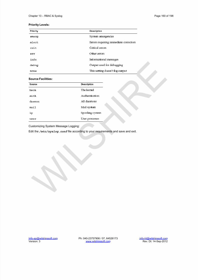
8/22/2019 Solaris%2010%20Handbook.pdf
http://slidepdf.com/reader/full/solaris201020handbookpdf 160/198
Chapter 13 – RBAC & Syslog Page 160 of 198
[email protected] Ph: 040-23757906 / 07, 64526173 [email protected] Version: 3 www.wilshiresoft.com Rev. Dt: 14-Sep-2012
Priority Levels:
Source Facilities:
Customizing System Message Logging:
Edit the /etc/syslog.conf file according to your requirements and save and exit.

8/22/2019 Solaris%2010%20Handbook.pdf
http://slidepdf.com/reader/full/solaris201020handbookpdf 161/198
Chapter 14 – Naming Services Page 161 of 198
[email protected] Ph: 040-23757906 / 07, 64526173 [email protected] Version: 3 www.wilshiresoft.com Rev. Dt: 14-Sep-2012
14. Naming Services
14.1. Name Service concept
Naming services store information in a central place, which enables users, machines, and applications tocommunicate across the network. This information can include the following.
1. Machine (host) names and addresses
2. User names
3. Passwords
4. Access permissions
5. Group membership, printers, and so on
Without a central naming service, each machine would have to maintain its own copy of this information. Namingservice information can be stored in files, maps, or database tables. If you centralize all data, administrationbecomes easier. A network information service enables machines to be identified by common names instead of numerical addresses. This makes communication simpler because users do not have to remember and try toenter cumbersome numerical addresses like 192.168.0.0. A network information service stores networkinformation on a server, which can be queried by any machine. The machines are known as clients of the server.
Whenever information about the network changes, instead of updating each client’s local file, an administrator
updates only the information stored by the network information service. Doing so reduces errors, inconsistenciesbetween clients, and the sheer size of the task. This arrangement, of a server providing centralized services toclients across a network, is known as client-server computing
14.2. Solaris Naming Services
The Solaris platform provides the following naming services.
1. DNS
2. /etc files, the original UNIX naming system
3. NIS, the Network Information Service
4. NIS+, the Network Information Service Plus
5. LDAP, the Lightweight Directory Access Protocol
Most modern networks use two or more of these services in combination. When more than one service is used,
the services are coordinated by the nsswitch.conf file.
Description of the DNS Naming Service
DNS is the naming service provided by the Internet for TCP/IP networks. DNS was developed so that machineson the network could be identified with common names instead of Internet addresses. DNS performs namingbetween hosts within your local administrative domain and across domain boundaries. The collection of networked machines that use DNS are referred to as the DNS namespace. The DNS namespace can be dividedinto a hierarchy of domains. A DNS domain is a group of machines. Each domain is supported by two or morename servers, a principal server and one or more secondary servers. Each server implements DNS by runningthe in.named daemon. On the client’s side, DNS is implemented through the “resolver.” The resolver’s function isto resolve users’ queries. The resolver queries a name server, which then returns either the requested informationor a referral to another server.
/etc Files Naming Service
The original host-based UNIX naming system was developed for standalone UNIX machines and then adaptedfor network use. Many old UNIX operating systems and machines still use this system, but the system is not wellsuited for large complex networks.
NIS Naming Service
The Network Information Service (NIS) was developed independently of DNS. DNS makes communicationsimpler by using machine names instead of numerical IP addresses. NIS focuses on making networkadministration more manageable by providing centralized control over a variety of network information. NIS storesinformation about the network, machine names and addresses, users, and network services. This collection of network information is referred to as the NIS namespace. NIS namespace information is stored in NIS maps. NIS

8/22/2019 Solaris%2010%20Handbook.pdf
http://slidepdf.com/reader/full/solaris201020handbookpdf 162/198
Chapter 14 – Naming Services Page 162 of 198
[email protected] Ph: 040-23757906 / 07, 64526173 [email protected] Version: 3 www.wilshiresoft.com Rev. Dt: 14-Sep-2012
maps were designed to replace UNIX /etc files, as well as other configuration files. NIS maps store much morethan names and addresses.
NIS uses a client-server arrangement which is similar to DNS. Replicated NIS servers provide services to NISclients. The principal servers are called master servers, and for reliability, the servers have backup, or slaveservers. Both master and slave servers use the NIS retrieval software and both store NIS maps
NIS+ Naming Service
The Network Information Service Plus (NIS+) is similar to NIS but with more features. However, NIS+ is not anextension of NIS. The NIS+ naming service is designed to conform to the shape of the organization. Unlike NIS,the NIS+ namespace is dynamic because updates can occur and be put into effect at any time by any authorizeduser. NIS+ enables you to store information about machine addresses, security information, mail information,Ethernet interfaces, and network services in one central location. This configuration of network information isreferred to as the NIS+ namespace. The NIS+ namespace is hierarchical. The NIS+ namespace is similar instructure to the UNIX directory file system. The hierarchical structure allows an NIS+ namespace to be configuredto conform to the logical hierarchy of an organization. The namespace’s layout of information is unrelated to itsphysical arrangement. Thus, an NIS+ namespace can be divided into multiple domains that can be administeredautonomously. Clients might have access to information in domains other than their own if the clients have theappropriate permissions.
NIS+ uses a client-server model to store and have access to the information contained in an NIS+ namespace.Each domain is supported by a set of servers. The principal server is called the primary server. The backupservers are called secondary servers. The network information is stored in 16 standard NIS+ tables in an internal
NIS+ database. Both primary and secondary servers run NIS+ server software and both maintain copies of NIS+tables. Changes made to the NIS+ data on the master server are incrementally propagated automatically to thesecondary servers.
NIS+ includes a sophisticated security system to protect the structure of the namespace and its information. NIS+uses authentication and authorization to verify whether a client’s request for information should be fulfilled. Authentication determines whether the information requester is a valid user on the network.
Authorization determines whether a particular user is allowed to have or modify the information requested.
LDAP Naming Services
Solaris 10 supports LDAP (Lightweight Directory Access Protocol) in conjunction with the Sun Java SystemDirectory Server (formerly Sun ONE Directory Server), as well as other LDAP directory servers.
The table above gives a comparative study of the various name services.

8/22/2019 Solaris%2010%20Handbook.pdf
http://slidepdf.com/reader/full/solaris201020handbookpdf 163/198
Chapter 14 – Naming Services Page 163 of 198
[email protected] Ph: 040-23757906 / 07, 64526173 [email protected] Version: 3 www.wilshiresoft.com Rev. Dt: 14-Sep-2012
14.3. The Name Service Switch
The name service switch is a file which is named, nsswitch.conf. The name service switch controls how a clientmachine or application obtains network information. Each machine has a switch file in it’s /etc directory. Each
line of that file identifies a particular type of network information, such as host, password, and group, followed byone or more locations of that information. The Solaris system automatically loads an nsswitch.conf file into everymachine’s /etc directory as part of the installation process. Four alternate (template) versions of the switch file
are also loaded into /etc for LDAP, NIS, NIS+, or files. No default file is provided for DNS, but you can edit any of these files to use DNS.
Format of the nsswitch.conf File
The nsswitch.conf file is essentially a list of 16 types of information
Default Search Criteria
The combination of nsswitch.conf file status message and action option determines what the routine does at eachstep. The combination of status and action make up the search criteria.
The switch’s default search criteria are the same for every source. As described in terms of the status messageslisted above, see the following.
SUCCESS=return. Stop looking for the information. Proceed using the information that has been found.
UNAVAIL=continue. Go to the next nsswitch.conf file source and continue searching. If this source is the last or
only source, return with a NOTFOUND status.
NOTFOUND=continue. Go to the next nsswitch.conf file source and continue searching. If this source is the lastor only source, return with a NOTFOUND status.
TRYAGAIN=continue. Go to the next nsswitch.conf file source and continue searching. If this source is the last or only source, return with a NOTFOUND status. Nondefault criteria are delimited by square brackets.
For example,
The networks: nis [NOTFOUND=return] files line specifies a nondefault criterion for the NOTFOUND status.Nondefault criteria are delimited by square brackets.
In this example, the search routine behaves as follows:
1. If the networks map is available, and contains the needed information, the routine returns with aSUCCESS status message.
2. If the networks map is not available, the routine returns with an UNAVAIL status message. By default, theroutine continues to search the appropriate /etc file.
3. If the networks map is available and found, but the map does not contain the needed information, theroutine returns with a NOTFOUND message. But, instead of continuing on to search the appropriate/etc file, which would be the default behavior, the routine stops searching.
4. If the networks map is busy, the routine returns with a TRYAGAIN status message and by defaultcontinues on to search the appropriate /etc file.
The nscd daemon caches switch information.
Some library routines do not periodically check the nsswitch.conf file to see whether the file has been changed.You must reboot the machine to make sure that the daemon and those routines have the latest information in thefile.
Maintaining multiple repositories for the same user is not recommended. By maintaining centralized password
management in a single repository for each user, you reduce the possibilities of confusion and error. If youchoose to maintain multiple repositories per user, update password information by using the passwd – r command.
passwd -r repository
If no repository is specified with the -r option, passwd updates the repositories listed in nsswitch.conf in reverseorder.

8/22/2019 Solaris%2010%20Handbook.pdf
http://slidepdf.com/reader/full/solaris201020handbookpdf 164/198
Chapter 14 – Naming Services Page 164 of 198
[email protected] Ph: 040-23757906 / 07, 64526173 [email protected] Version: 3 www.wilshiresoft.com Rev. Dt: 14-Sep-2012
14.4. Domain Name Service
DNS is the name service used on the Internet. Let’s understand the jargon of DNS.
Domains
DNS allows hierarchal domains. It uses the domainname to describe a generic “ownership” of the hosts.
Root DomainIn DNS the domain name space is very similar to the UNIX file system. One domain at the root of the name spacecontains all other domains. Known as the root domain, this domain is usually written as a single dot (.) at the endof the domain name.
(Root Level)
us arpa com edu gov mil net org in (Top Level )
Top Level Domains
DNS defines several “top level” domains. These domains are global in nature. For example, some common toplevel domains are edu, com, net, org, gov and mil. The names of these top level domains make an attempt todescribe the type of organizations they contain.
Under each top-level domain there may be any number of sub-domains. Under each of these second-leveldomains there may be other sub-domains.
(When the Internet was first put into operation, it only served hosts and organizations within the United States.Over time the Internet expanded to locations outside the United States. The International Standards Organization(ISO) developed a series of standard two-letter country codes. These two letter domains were inserted under theroot domain, with special provisions that the existing US top-level domains could remain unchanged.
Locations outside the US sub-divide their top-level domain in a manner similar to the US top-level domains.)
Traversing the domain tree
Domain names read from left to right, where the left-most component of the name is the furthest point from theroot of the name space. For example, the consider a fictious name alice.wonderland.carroll.org might describe ahost located in wonderland in the carroll domain under the org top-level domain. To be precise, there should be adot at the end of any domain/host name (e.g., alice.wonderland.carroll.org.). The dot signifies that the domain isfully qualified all the way to the root domain. When the trailing dot is left off the name, the name is said to bepartially qualified.
DNS Servers
Under DNS, name servers are programs that store information about domain namespace. A name server maintains database files that contain the master information for a domain. The client machines within the domainare configured in such a way that they will query the local name server when name to address mapping isrequired.
External hosts take a slightly different approach to resolution of name to address mappings. The remote host willquery its local name server to get the name to address mapping. The local name server may not have the
information required, so it queries another name server in an attempt to resolve the query. This (often recursive)process will continue until the local name server gets a valid mapping (query is resolved), or until appropriatename servers have been queried and failed to return the requested information (host not found).
Primary Name Servers
The primary name server obtains information about the domain from disk files contained on the name server host.The domain may actually have several primary name servers in an attempt to spread the work load around andprovide better service.
Secondary Name Servers

8/22/2019 Solaris%2010%20Handbook.pdf
http://slidepdf.com/reader/full/solaris201020handbookpdf 165/198
Chapter 14 – Naming Services Page 165 of 198
[email protected] Ph: 040-23757906 / 07, 64526173 [email protected] Version: 3 www.wilshiresoft.com Rev. Dt: 14-Sep-2012
Each domain can also define a number of secondary name servers. The secondary name servers obtain their databases from the primary name servers through a process called “zone transfer.” These secondary nameservers are queried in the event the primary name server(s) do not respond to a query.
Caching Name Server
Caching name servers have no direct access to any authoritative information about the domain. These nameservers query primary and secondary name servers with DNS requests, and store the results away in a memory
cache for future reference. When these servers spot a DNS look-up request on the network, they reply with theinformation they have stored in their respective caches. Caching name servers usually contain valid data, butbecause they don’t load information directly from primary name servers, the data can become stale. Cachingname servers are not considered authoritative name servers.
Root Name Servers
In order to provide a master list of name servers available on the Internet, the Network Information Center (NIC)maintains a group of root name servers. These name servers provide authoritative information about specific toplevel domains. When a local name server cannot resolve an address, it queries the root name server for theappropriate domain for information which may allow the local name server to resolve the address.
DNS Clients
DNS clients comprise a series of library calls, which issue RPC requests to a DNS server. These library routinesare referred to as “resolver code.” Whenever a system requires a name to IP address mapping, the sy stemsoftware executes a gethostbyname () library call. The resolver code contacts the appropriate name service
daemon to resolve the query.
/etc/resolv.conf File
In order to make DNS operate, the administrator must configure the /etc/resolv.conf file on each host. This
file tells the name service resolution routines where to find DNS information. The format of the entries in the/etc/resolv.conf file is keyword value.
nameserver: Valid values for name servers are IP addresses in standard dot notation.
domain: The domain value will be appended to any hostname which doesnt end in a dot. If a user types telnetalice, the resolver will automatically append .wonderland.carroll.org to the request such that the telnet session willactually be issued as telnet alice.wonderland.carroll.org.
DNS Database Files
The DNS service consults a series of database files in order to resolve name service queries. Such database filesare often called as db files. In order to provide scalability and modularity, the database information is split intoseveral files as described below:
1. named.hosts – This provides the hostname to IP address mapping for the hosts within the domain name.
2. named.rev – This database provides the IP address to hostname mapping (reverse mapping) for thehosts on network address.
Name Service Resource Records
The information stored in the database files is organised into resource records, and the format of these records isdetermined by the DNS design specifications.
The different types of records are:
Comment Records
SOA (Start of Authority) Records
NS (Name Server) Records
A (Address) Records
PTR (Pointer) Records
MX (Mail Exchanger) Records
CNAME (Canonical name) Records
TXT (Text) Records
RP (Responsible Person) Records
Comment Records

8/22/2019 Solaris%2010%20Handbook.pdf
http://slidepdf.com/reader/full/solaris201020handbookpdf 166/198
Chapter 14 – Naming Services Page 166 of 198
[email protected] Ph: 040-23757906 / 07, 64526173 [email protected] Version: 3 www.wilshiresoft.com Rev. Dt: 14-Sep-2012
DNS provides a method for embedding comments in the db files. It begins with a semicolon (;). Comments areneeded in an attempt to explain the local site setup.
SOA Records
This provides information about management of data within the domain. The SOA record must start in column 1.The format is shown below:
domain class SOA primary_server rp (
serial_number
refresh_value
retry_value
expiration_value
TTL)
The domain field is the domain name.
The class field allows the administrator to define the class of data. Currently, only one class is used. The IN classdefines Internet data.
SOA field tells the resolver that this is a start of authority record for domain.
The primary server field is the fully qualified host name of the primary name server for this domain.
The rp field gives the fully qualified email address of the person responsible for this domain
The serial number field is used by the secondary name servers. This field is a “counter” which gives the versionnumber for the file. This number should be incremented every time the file is altered. When the information storedon the secondary name servers expires, the servers contact the primary name server to obtain new information. If the serial number of the information obtained from the primary server is larger than the serial number of thecurrent information, a full zone transfer is performed. If the serial number from the primary name server is smaller than the current information, the secondary name server discards the information from the primary name server.
The refresh_value field is used by the secondary name servers. The value in this field tells the secondary servershow long (in seconds) to keep the data before they obtain a new copy from the primary name server. If the valueis too small, the name server may overload the network with zone transfers. If the value is too large, informationmay become stagnant and changes may not propagate efficiently from the primary to the secondary nameservers.
The retry_value field is used by the secondary name servers. The value in this field tells the secondary servershow long (in seconds) to wait before attempting to contact a non-responsive primary name server.
The expiration_value field is used by the secondary name servers. The value in this field tells the secondaryservers to expire their information after value seconds. Once the secondary server expires its data, it stopsresponding to name service requests.
The TTL field tells name servers how long they can “cache” the response from the name server befor e they purge(discard) the information obtained in response to a query. Example:
wonder.com. IN SOA alice.wonder.com. root.alice.wonder.com. (
2005111401 ; serial – format YYYYMMDD##
10800 ; Refresh every 3 hours
3600 ; Retry after an hour
604800 ; Expire data after 1 week
86400 ) ; TTL for cached data is 1 day
NS Records
The NS records define the name servers within a domain. The NS record starts in column 1 of the file. The formatof an NS record follows: domain class NS fully_qualified_hostname. An example appears below.
wonder.com. IN NS alice.wonder.com.
A Records

8/22/2019 Solaris%2010%20Handbook.pdf
http://slidepdf.com/reader/full/solaris201020handbookpdf 167/198
Chapter 14 – Naming Services Page 167 of 198
[email protected] Ph: 040-23757906 / 07, 64526173 [email protected] Version: 3 www.wilshiresoft.com Rev. Dt: 14-Sep-2012
The A (Address) records provide the information used to map host names to IP addresses. The A record mustbegin in column 1 of the file. The format of an A record is fully_qualified_hostname class A address. Example:
alice.wonder.com. IN A 200.200.0.1
PTR Records
The pointer records provide the information for reverse mapping (looking up a host name from an IP address).The PTR record must begin in column1 of the file. The format of the PTR record is address class PTR
fully_qualified_hostname. The PTR record does have one quirk: the address portion appears to be writtenbackwards, and contains information the user typically doesnt see. The information is presented in this format inorder to simplify the look-up procedure, and to maintain the premise that the information at the left of the record isfurthest from the root of the domain.
Ex: 1.0.200.200.in-addr.arpa. IN PTR alice.wonder.com.
MX Records
The mail exchanger records provide a way for remote hosts to determine where e-mail should be delivered for adomain. The MX records must begin in column 1 of the db files. The format of MX records isfully_qualified_hostname class MX preference fully_qualified_mail_hostname.
There should be an MX record for each host within a domain. The preference field tells the remote host thepreferred place to deliver the mail for the domain. This allows e-mail to be delivered in the event that the primarymail server is down. The remote host will try to deliver e-mail to the host with the lowest preference value first. If
that fails, the remote host will attempt to deliver the e-mail to the host with the next lowest preference value.Examples appear below:
alice.wonder.com. IN MX mail.wonder.com.
CNAME Records
The CNAME records provide a way to alias host names.
TXT Records
The TXT records allow the administrator to add text information to the db files giving more information about thedomain. The TXT records must start in column 1 of the db file, and the format of TXT records is hostname classTXT “Random text about hostname in this domain”.
alice IN TXT “Machine Alice is in Wonderland”
RP Records
These records define the person responsible for the domain. The RP records must start in column 1 of the dbfiles. The format of an RP record is hostname class RP fully_qualified_email_address fully_qualified_hostname.
alice IN user1.alice.wonder.com. queen.wonder.com.
queen IN TXT “The Responsible Person”
Configuring DNS
The Solaris 10 operating system ships with the BIND 9.x DNS name server. The DNS/BIND named service canbe managed by using the Sevice Management Facility (SMF).
Tip – Temporarily disabling a service by using the -t option provides some protection for the service configuration.If the service is disabled with the –t option, the original settings would be restored for the service after a reboot. If the service is disabled without -t, the service will remain disabled after reboot.
The Fault Managed Resource Identifiers (FMRIs) for the DNS service are
svc:/network/dns/server:<instance> and
svc:/network/dns/client:<instance>.
If you need to start the DNS service with different options (for example with a configuration file other than/etc/named.conf), change the start method property of the DNS server manifest by using the svccfg command.Multiple SMF service instances are only needed if you want to run multiple copies of BIND 9 name service. Eachadditional instance can be specified in the DNS server manifest with a different start method. While it isrecommended that you use svcadm to administer the server, you can use rndc as well. SMF is aware of the statechange of the BIND 9 named service, whether administered by using svcadm or rndc.

8/22/2019 Solaris%2010%20Handbook.pdf
http://slidepdf.com/reader/full/solaris201020handbookpdf 168/198
Chapter 14 – Naming Services Page 168 of 198
[email protected] Ph: 040-23757906 / 07, 64526173 [email protected] Version: 3 www.wilshiresoft.com Rev. Dt: 14-Sep-2012
Note – SMF will not be aware of the BIND 9 named service if the service is manually executed from the commandline.
DNS Server Configuration
# vi /etc/defaultdomain
wil.com
Save and exit
# domainname wil.com
# mkdir /var/named
# cd /var/named
# vi named.hosts
wil.com. IN SOA wstsun1.wil.com. root.wstsun1.wil.com. (
2005111401
10800
3600
604800
86400 )
wil.com. IN NS wstsun1.wil.com.
wstsun1 IN A 200.200.0.1
wstsun2 IN A 200.200.0.2 wstsun3 IN A 200.200.0.3
And save and exit
# vi named.rev
0.200.200.in-addr.arpa. IN SOA wstsun1.wil.com. root.wstsun1.wil.com. (
2005111401
10800
3600
604800
86400 )
0.200.200.in-addr.arpa. IN NS wstsun1.wil.com.
1 IN PTR wstsun1
2 IN PTR wstsun23 IN PTR wstsun3
# cd /etc
# vi named.conf
options {
directory “/var/named” ;
};
zone “wil.com” {
type master;
file “named.hosts” ;
};
zone “0.200.200.in-addr.arpa” {
type master;
file “named.rev”;
}
};
# svcadm enable \*dns\*
DNS Client Configuration
# vi /etc/nsswitch.conf
hosts dns files
Save and exit

8/22/2019 Solaris%2010%20Handbook.pdf
http://slidepdf.com/reader/full/solaris201020handbookpdf 169/198
Chapter 14 – Naming Services Page 169 of 198
[email protected] Ph: 040-23757906 / 07, 64526173 [email protected] Version: 3 www.wilshiresoft.com Rev. Dt: 14-Sep-2012
# vi /etc/resolv.conf
domain wil.com
nameserver 200.200.0.1
Save and exit
# svcadm restart \*dns\*
# nslookup
>
14.5. Network Information Service
NIS Fundamentals
By running NIS, the system administrator can distribute administrative databases, called maps, among a varietyof servers (master and slaves). The administrator can update those databases from a centralized location in anautomatic and reliable fashion to ensure that all clients share the same naming service information in a consistentmanner throughout the network. NIS was developed independently of DNS and has a slightly different focus.Whereas DNS focuses on making communication simpler by using machine names instead of numerical IPaddresses, NIS focuses on making network administration more manageable by providing centralized control over a variety of network information. NIS stores information not only about machine names and addresses, but alsoabout users, the network itself, and network services. This collection of network information is referred to as theNIS namespace.
NIS Architecture
NIS uses a client-server arrangement. NIS servers provide services to NIS clients. The principal servers arecalled master servers, and for reliability, they have backup, or slave servers. Both master and slave servers usethe NIS information retrieval software and both store NIS maps. NIS uses domains to arrange the machines,users, and networks in its namespace. However, it does not use a domain hierarchy; an NIS namespace is flat. An NIS domain cannot be connected directly to the Internet using just NIS. However, organizations that want touse NIS and also be connected to the Internet can combine NIS with DNS.
NIS Machine Types
There are three types of NIS machines.
1. Master server
2. Slave servers
3. Clients of NIS servers
Any machine can be an NIS client, but only machines with disks should be NIS servers, either master or slave.Servers are also clients, typically of themselves.
NIS Servers
The NIS server does not have to be the same machine as the NFS file server. NIS servers come in two varieties,master and slave. The machine designated as master server contains the set of maps that the systemadministrator creates and updates as necessary. Each NIS domain must have one, and only one, master server,which can propagate NIS updates with the least performance degradation. You can designate additional NISservers in the domain as slave servers. A slave server has a complete copy of the master set of NIS maps.Whenever the master server maps are updated, the updates are propagated among the slave servers. Slaveservers can handle any overflow of requests from the master server, minimizing “server unavailable” errors.
NIS Clients
NIS clients run processes that request data from maps on the servers. Clients do not make a distinction betweenmaster and slave servers, since all NIS servers should have the same information.
NIS Elements
The NIS naming service is composed of the following elements:
1. Domains
2. Daemons
3. Utilities
4. Maps

8/22/2019 Solaris%2010%20Handbook.pdf
http://slidepdf.com/reader/full/solaris201020handbookpdf 170/198
Chapter 14 – Naming Services Page 170 of 198
[email protected] Ph: 040-23757906 / 07, 64526173 [email protected] Version: 3 www.wilshiresoft.com Rev. Dt: 14-Sep-2012
5. NIS Command Set
NIS Domain
An NIS domain is a collection of machines which share a common set of NIS maps.
NIS Daemons
NIS service is provided by five daemons. The NIS service is managed by the Service Management Facility.
NIS Daemon Summary
NIS Utilities
NIS MAPS
NIS maps were designed to replace UNIX /etc files, as well as other configuration files, so they store much morethan names and addresses. On a network running NIS, the NIS master server for each NIS domain maintains aset of NIS maps for other machines in the domain to query. NIS slave servers also maintain duplicates of themaster server’s maps. NIS client machines can obtain namespace information from either master or slaveservers. NIS maps are essentially two-column tables. One column is the key and the other column is informationrelated to the key. NIS finds information for a client by searching through the keys.
NIS and the Service Management Facility:
The NIS Fault Managed Resource Identifiers (FMRIs) are
svc:/network/nis/server:<instance> for the NIS server and
svc:/network/nis/client:<instance> for the NIS client.
Preparing the Master Server Involves
1. Preparing Source Files for Conversion to NIS Maps
2. Check the source files on the master server to make sure they reflect an up-to-date picture of your system.

8/22/2019 Solaris%2010%20Handbook.pdf
http://slidepdf.com/reader/full/solaris201020handbookpdf 171/198
Chapter 14 – Naming Services Page 171 of 198
[email protected] Ph: 040-23757906 / 07, 64526173 [email protected] Version: 3 www.wilshiresoft.com Rev. Dt: 14-Sep-2012
3. Copy all of these source files, except passwd, to the DIR directory that you have selected.
4. Copy the passwd file to the PWDIR directory that you have selected.
5. Preparing the Makefile
NOTE
Source Files Directory
The source files should be located in the /etc directory, on the master server or in some other directory. Havingthem in /etc is undesirable because the contents of the maps are then the same as the contents of the local files
on the master server. This is a special problem for passwd and shadow files because all users have access to themaster server maps and the root password would be passed to all NIS clients through the passwd map. However,if you put the source files in some other directory, you must modify the Makefile in /var/yp by changing theDIR=/etc line to DIR=/your-choice, where your-choice is the name of the directory you will be using to store
the source files. This allows you to treat the local files on the server as if they were those of a client. (It is goodpractice to first save a copy of the original Makefile.)
After checking the source files and copying them into the source file directory, you now need to convert thosesource files into the ndbm format maps that the NIS service uses. This is done automatically for you by ypinitwhen called on the master server. The ypinit script calls the program make, which uses the Makefile locatedin the /var/yp directory. A default Makefile is provided for you in the /var/yp directory and contains the
commands needed to transform the source files into the desired ndbm format maps.
The function of the Makefile is to create the appropriate NIS maps for each of the databases listed under all. After passing through makedbm the data is collected in two files, mapname.dir and mapname.pag . Both filesare in the /var/yp/domainname directory on the master server. The Makefile builds passwd maps from the/PWDIR/passwd , /PWDIR/shadow , and /PWDIR/security/passwd.adjunct files, as appropriate.
Setting Up the Master Server
The ypinit script sets up master and slave servers and clients to use NIS. It also initially runs make to create
the maps on the master server.
Copy the contents of the nsswitch.files file to the nsswitch.conf file.
# cp /etc/nsswitch.files /etc/nsswitch.conf
Edit the /etc/hosts or /etc/inet/ipnodes file to add the name and IP address of each of the NIS servers.
Build new maps on the master server.
# /usr/sbin/ypinit -m
When ypinit prompts for a list of other machines to become NIS slave servers, type the name of the server youare working on, along with the names of your NIS slave servers.
When ypinit asks whether you want the procedure to terminate at the first nonfatal error or continue despitenonfatal errors, type y .
Note – A nonfatal error can appear when some of the map files are not present. This is not an error that affectsthe functionality of NIS. You might need to add maps manually if they were not created automatically.
ypinit asks whether the existing files in the /var/yp/domainname directory can be destroyed.
This message is displayed only if NIS has been previously installed.
After ypinit has constructed the list of servers, it invokes make.
This program uses the instructions contained in the Makefile (either the default one or the one you modified)located in /var/yp . The make command cleans any remaining comment lines from the files you designated. It
also runs makedbm on the files, creating the appropriate maps and establishing the name of the master server for each map.
If the map or maps being pushed by the Makefile correspond to a domain other than the one returned by thecommand domainname on the master, you can make sure that they are pushed to the correct domain by startingmake in the ypinit shell script with a proper identification of the variable DOM, as follows:
# make DOM=domainname password
This pushes the password map to the intended domain, instead of the domain to which the master belongs.

8/22/2019 Solaris%2010%20Handbook.pdf
http://slidepdf.com/reader/full/solaris201020handbookpdf 172/198
Chapter 14 – Naming Services Page 172 of 198
[email protected] Ph: 040-23757906 / 07, 64526173 [email protected] Version: 3 www.wilshiresoft.com Rev. Dt: 14-Sep-2012
To enable NIS as the naming service, type the following.
# cp /etc/nsswitch.nis /etc/nsswitch.conf
This replaces the current switch file with the default NIS-oriented switch file. You can edit this file as necessary.
Starting and Stopping NIS Service on the Master Server
Now that the master maps are created, you can start the NIS daemons on the master server and begin service.
When you enable the NIS service, ypserv and ypbind start on the server. When a client requests information fromthe server, ypserv is the daemon that answers information requests from clients after looking them up in the NISmaps. The ypserv and ypbind daemons are administered as a unit.
There are three ways that NIS service can be started or stopped on a server:
1. automatically invoking the /usr/lib/netsvc/yp/ypstart script during the boot process
2. using the Service Management Facility
3. using the ypstart(1M) and ypstop (1M) commands from the command line
Setting Up NIS Slave Servers
Your network can have one or more slave servers. Having slave servers ensures the continuity of NIS serviceswhen the master server is not available.
Preparing a Slave Server
Before actually running ypinit to create the slave servers, you should run the domainname command on each NISslave to make sure the domain name is consistent with the master server.
Note – Domain names are case-sensitive.
Make sure that the network is working properly before you configure an NIS slave server. In particular, check tobe sure you can use rcp to send files from the master NIS server to NIS slaves.
The following procedure shows how to set up a slave server.
Edit the /etc/hosts or /etc/inet/ipnodes file on the slave server to add the name and IP addresses of allthe other NIS servers.
Change directory to /var/yp on the slave server.
Note – You must first configure the new slave server as an NIS client so that it can get the NIS maps from the
master for the first time.Initialize the slave server as a client.
# /usr/sbin/ypinit -c
The ypinit command prompts you for a list of NIS servers. Enter the name of the local slave you are working onfirst, then the master server, followed by the other NIS slave servers in your domain in order from the physicallyclosest to the furthest in network terms.
Determine if the NIS client is running, then start the client service as needed.
# svcs network/nis/client
STATE STIME FMRI
online 20:32:56 svc:/network/nis/client:default
If svc:/network/nis/client is displayed with an online state, then NIS is running. If the service state is
disabled, then NIS is not running.a. If the NIS client is running, restart the client service.
# svcadm restart network/nis/client
b. If the NIS client is not running, start the client service.
# svcadm enable network/nis/client
c. Initialize this machine as a slave.
# /usr/sbin/ypinit -s master

8/22/2019 Solaris%2010%20Handbook.pdf
http://slidepdf.com/reader/full/solaris201020handbookpdf 173/198
Chapter 14 – Naming Services Page 173 of 198
[email protected] Ph: 040-23757906 / 07, 64526173 [email protected] Version: 3 www.wilshiresoft.com Rev. Dt: 14-Sep-2012
Where master is the machine name of the existing NIS master server.
Repeat the procedures described in this section for each machine you want configured as an NIS slave server.
The following procedure shows how to start NIS on a slave server.
Stop the client service and start all NIS server processes.
# svcadm disable network/nis/client
# svcadm enable network/nis/server
Setting Up NIS Clients
The two methods for configuring a client machine to use NIS as its naming service are explained below.
The recommended method for configuring a client machine to use NIS is to login to the machine as root and run ypinit -c .
# ypinit -c
You will be asked to name NIS servers from which the client obtains naming service information. You can list asmany master or slave servers as you want. The servers that you list can be located anywhere in the domain. It isa better practice to first list the servers closest (in network terms) to the machine, than those that are on moredistant parts of the net.
Broadcast method. An older method of configuring a client machine to use NIS to log in to the machine as root,
set the domain name with the domainname command, then run ypbind. ypstart will automatically invoke the NISclient in broadcast mode (ypbind -broadcast), if the /var/yp/binding/‘domainname‘/ypservers file does not exist.
# domainname doc.com
# mv /var/yp/binding/‘domainname‘/ypservers /var/yp/binding/‘domainname‘/ypservers.bak
# ypstart
When you run ypbind , it searches the local subnet for an NIS server. If it finds a subnet, ypbind binds to it. Thissearch is referred to as broadcasting. If there is no NIS server on the client’s local subnet, ypbind fails to bind
and the client machine is not able to obtain namespace data from the NIS service.

8/22/2019 Solaris%2010%20Handbook.pdf
http://slidepdf.com/reader/full/solaris201020handbookpdf 174/198
Chapter 15 – Advanced Installations Page 174 of 198
[email protected] Ph: 040-23757906 / 07, 64526173 [email protected] Version: 3 www.wilshiresoft.com Rev. Dt: 14-Sep-2012
15. Advanced Installations
15.1. Solaris Containers
A Solaris Container is a complete runtime environment for applications. Solaris 10 Resource Manager and SolarisZones software partitioning technology are both parts of the container.
15.1.1. Resource Management
Resource Manager enables us to control how applications use available system resources. Using the ResourceManager, we can
1. Allocate computing resources, such as processor time
2. Monitor how the allocations are being used, then adjust the allocations as necessary
3. Generate extended accounting information for analysis, billing, and capacity planning
A workload is an aggregation of all processes of an application or group of applications.
If resource management features are not used, the Solaris Operating System responds to workload demands byadapting to new application requests dynamically. By using the Resource Manager we can perform resourceallocation at the application level. We can,
1. Restrict access to a specific resource2. Offer resources to workloads on a preferential basis
3. Isolate workloads from each another
Resource management is implemented through a collection of algorithms. The algorithms handle the series of capability requests that an application presents in the course of its execution.
15.1.2. Solaris Zones
A growing number of users are interested in improving the utilization of their computing resources throughconsolidation and aggregation. Consolidation is already common in mainframe environments, where technologyto support running multiple applications and even operating systems on the same hardware has been indevelopment since the late 1960’s. Such technology is now becoming an important differentiator in other markets(such as Unix/Linux servers), both at the low end (virtual web hosting) and high end (traditional data center server consolidation).
Zones are a new operating system abstraction for partitioning systems, allowing multiple applications to run inisolation from each other on the same physical hardware. This isolation prevents processes running within a zonefrom monitoring or affecting processes running in other zones, seeing each other’s data, or manipulating theunderlying hardware. Zones also provide an abstraction layer that separates applications from physical attributesof the machine on which they are deployed, such as physical device paths and network interface names.
Much of the previous work in this area has involved running multiple operating system instances on a singlesystem, either through the use of hardware partitioning [IBMs lpar] or virtual machine monitors. Hardwarepartitioning, while providing a very high degree of application isolation, is costly to implement and is generallylimited to high-end systems. In addition, the granularity of resource allocation is often poor, particularly in the areaof CPU assignment. Virtual machine implementations can be much more granular in how resources are allocated(even time-sharing multiple VM’s on a single CPU), but suffer significant performance overheads. With either approach, the cost of administering multiple operating system instances can be substantial.
More recently, a number of projects have explored the idea of virtualizing the operating system environment,
rather than the physical hardware. These efforts differ from virtual machine implementations in that there is onlyone underlying operating system kernel, which is enhanced to provide increased isolation between groups of processes. The result is the ability to run multiple applications in isolation from each other within a singleoperating system instance.
Zones build on this concept by extending this virtual operating system environment to include many of thefeatures of a separate machine, such as a perzone console, system log, packaging database, run level, identity(including name services), and interprocess communication facility. For example, each zone has a virtualizedview of the process table (as reflected in the /proc file system) that reflects only the processes running in thatzone, as well as a virtualized /etc/mnttab file that shows only file system mounts within the zone.

8/22/2019 Solaris%2010%20Handbook.pdf
http://slidepdf.com/reader/full/solaris201020handbookpdf 175/198
Chapter 15 – Advanced Installations Page 175 of 198
[email protected] Ph: 040-23757906 / 07, 64526173 [email protected] Version: 3 www.wilshiresoft.com Rev. Dt: 14-Sep-2012
A set of administrative tools have been developed to manage zones, allowing them to be configured, installed,patched, upgraded, booted, rebooted, and halted. As a result, zones can be administered in a manner very similar to separate machines. In fact, some types of administration are significantly easier; for example, an administrator can apply a patch to every zone on a system with a single command.
A zone can either be bound to a dedicated pool of resources (such as a number of CPUs or a quantity of physicalmemory), or can share resources with other zones according to defined proportions. This allows the use of zonesboth on large systems (where dedicated resources may be most appropriate) and smaller ones (where a greater
degree of sharing is necessary). It also allows administrators to make appropriate tradeoffs depending on therelative importance of resource isolation versus utilization.
Zones provide for the delegation of many of the expected administrative controls for the virtual operating systemenvironment. Since each zone has its own name service identity, it also has its own notion of a password file andits own root user. The proportion of CPU resources that a zone can consume can be defined by an administator,and then that share can be further divided among workloads running in the zone by the (potentially different) zoneadministrator. In addition, the privileges available within a zone (even to the root user) are restricted to those thatcan only affect the zone itself. As a result, even if a zone is compromised by an intruder, the compromise will notaffect other zones in the system or the system as a whole.
Zones also allow sharing of file system data, particularly read-only data such as executables and libraries.Portions of the file system can be shared between all zones in the system through use of the read-only loopbackfile system (or lofs), which allows a directory and its contents to be spliced into another part of the file system.This not only substantially reduces the amount of disk space used by each zone, but reduces the time to install
zones and apply patches, and allows for greater sharing of text pages in the virtual memory system.NOTE: Zones are part of the N1 Grid Containers feature in Solaris 10 and the container technology is still under development.
The Solaris Zones partitioning technology is used to virtualize operating system services and provide an isolatedand secure environment for running applications. A zone is a virtualized operating system environment createdwithin a single instance of the Solaris Operating System. When you create a zone, you produce an applicationexecution environment in which processes are isolated from the rest of the system. This isolation preventsprocesses that are running in one zone from monitoring or affecting processes that are running in other zones.Even a process running with superuser credentials cannot view or affect activity in other zones.
A zone also provides an abstract layer that separates applications from the physical attributes of the machine onwhich they are deployed. Examples of these attributes include physical device paths. Zones can be used on anymachine that is running the Solaris 10 release. The upper limit for the number of zones on a system is 8192. Thenumber of zones that can be effectively hosted on a single system is determined by the total resource
requirements of the application software running in all of the zones.There are two types of non-global zone root file system models: sparse and whole root. The sparse root zonemodel optimizes the sharing of objects. The whole root zone model provides the maximum configurability.
When to Use Zones
Zones are ideal for environments that consolidate a number of applications on a single server. The cost andcomplexity of managing numerous machines make it advantageous to consolidate several applications on larger,more scalable servers. Zones enable more efficient resource utilization on your system. Dynamic resourcereallocation permits unused resources to be shifted to other containers as needed. Fault and security isolationmean that poorly behaved applications do not require a dedicated and underutilized system. With the use of zones, these applications can be consolidated with other applications. Zones allow you to delegate someadministrative functions while maintaining overall system security.
How Zones Work
A non-global zone can be thought of as a box. One or more applications can run in this box without interactingwith the rest of the system. Solaris zones isolate software applications or services by using flexible, software-defined boundaries. Applications that are running in the same instance of the Solaris Operating System can thenbe managed independently of one other. Thus, different versions of the same application can be run in differentzones, to match the requirements of your configuration.
Each zone that requires network connectivity has one or more dedicated IP addresses. A process assigned to azone can manipulate, monitor, and directly communicate with other processes that are assigned to the samezone. The process cannot perform these functions with processes that are assigned to other zones in the systemor with processes that are not assigned to a zone. Processes that are assigned to different zones are only able tocommunicate through network APIs.

8/22/2019 Solaris%2010%20Handbook.pdf
http://slidepdf.com/reader/full/solaris201020handbookpdf 176/198
Chapter 15 – Advanced Installations Page 176 of 198
[email protected] Ph: 040-23757906 / 07, 64526173 [email protected] Version: 3 www.wilshiresoft.com Rev. Dt: 14-Sep-2012
Every Solaris system contains a global zone. The global zone has a dual function. The global zone is both thedefault zone for the system and the zone used for system-wide administrative control. All processes run in theglobal zone if no non-global zones, referred to simply as zones, are created by the global administrator.
The global zone is the only zone from which a non-global zone can be configured, installed, managed, or uninstalled. Only the global zone is bootable from the system hardware. Administration of the systeminfrastructure, such as physical devices, routing, or dynamic reconfiguration (DR), is only possible in the globalzone. Appropriately privileged processes running in the global zone can access objects associated with other
zones.
Unprivileged processes in the global zone might be able to perform operations not allowed to privilegedprocesses in a non-global zone. For example, users in the global zone can view information about every processin the system. If this capability presents a problem for your site, you can restrict access to th e global zone.
Each zone, including the global zone, is assigned a zone name. The global zone always has the name global.Each zone is also given a unique numeric identifier, which is assigned by the system when the zone is booted.The global zone is always mapped to ID 0. Each zone also has a node name that is completely independent of the zone name. The node name is assigned by the administrator of the zone. Each zone has a path to its rootdirectory that is relative to the global zone’s root directory. The scheduling class for a non -global zone is set to thescheduling class for the system.
You can also set the scheduling class for a zone through the dynamic resource pools facility. If the zone isassociated with a pool that has its pool.scheduler property set to a valid scheduling class, then processes runningin the zone run in that scheduling class by default.
Features Summary:

8/22/2019 Solaris%2010%20Handbook.pdf
http://slidepdf.com/reader/full/solaris201020handbookpdf 177/198
Chapter 15 – Advanced Installations Page 177 of 198
[email protected] Ph: 040-23757906 / 07, 64526173 [email protected] Version: 3 www.wilshiresoft.com Rev. Dt: 14-Sep-2012
15.2. Custom JumpStart Introduction
The custom JumpStart installation method is a command –line interface that enables you to automatically install or upgrade several systems, based on profiles that you create. The profiles define specific software installationrequirements. You can also incorporate shell scripts to include preinstallation and postinstallation tasks. Youchoose which profile and scripts to use for installation or upgrade. The custom JumpStart installation methodinstalls or upgrades the system, based on the profile and scripts that you select. Also, you can use a sysidcfg file
to specify configuration information so that the custom JumpStart installation is completely hands-off.Custom JumpStart Example Scenario
The custom JumpStart process can be described by using an example scenario. In this example scenario, thesystems need to be set up with the following parameters:
Install Solaris on 100 new systems.
Seventy of the systems are SPARC based systems that are owned by the engi neering group and need to beinstalled as standalone systems with the Solaris OS software group for developers. The remaining 30 systemsare x86 based, owned by the marketing group and need to be installed as standalone systems with the SolarisOS software group for end users.
First, the system administrator must create a rules file and a profile for each group of systems. The rules file is atext file that contains a rule for each group of systems or single systems on which you want to install the Solarissoftware. Each rule distinguishes a group of systems that are based on one or more system attributes. Each rule
also links each group to a profile. A profile is a text file that defines how the Solaris software is to be installed oneach system in the group. Both the rules file and profile must be located in a JumpStart directory. For the examplescenario, the system administrator creates a rules file that contains two different rules, one for the engineeringgroup and another for the marketing group. For each rule, the system’s network number is used to distinguish theengineering group from the marketing group. Each rule also contains a link to an appropriate profile. For example,in the rule for the engineering group, a link is added to the profile, eng_profile, which was created for theengineering group. In the rule for the marketing group, a link is added to the profile, market_profile, which wascreated for the marketing group. You can save the rules file and the profiles on a diskette or on a server.
1. A profile diskette is required when you want to perform custom JumpStart installations on nonnetworked,standalone systems.
2. A profile server is used when you want to perform custom JumpStart installations on networked systemsthat have access to a server. After creating the rules file and profiles validate the files with the checkscript. If the check script runs successfully, the rules.ok file is created. The rules.ok is a generated versionof the rules file that the JumpStart program uses to install the Solaris software.
How the JumpStart Program Installs Solaris Software
After you validate the rules file and the profiles, you can begin a custom JumpStart installation. The JumpStartprogram reads the rules.ok file. Then, the JumpStart program searches for the first rule with defined systemattributes that match the system on which the JumpStart program is attempting to install the Solaris software. If amatch occurs, the JumpStart program uses the profile that is specified in the rule to install the Solaris software onthe system.
Figure 15 –1 illustrates how a custom JumpStart installation works with more than one system on a network.Previously, the system administrator set up different profiles and saved the profiles on a single server. Thesystem administrator initiates the custom JumpStart installation on one of the engineering systems. TheJumpStart program accesses the rules files in the JumpStart/ directory on the server. The JumpStart programmatches the engineering system to rule 1. rule 1 specifies that the JumpStart program use Engineering Group’sProfile to install the Solaris software. The JumpStart program reads Engineering Group’s Profile and installs theSolaris software, based on the instructions that the system administrator specified in Engineering Group’s Profile.

8/22/2019 Solaris%2010%20Handbook.pdf
http://slidepdf.com/reader/full/solaris201020handbookpdf 178/198
Chapter 15 – Advanced Installations Page 178 of 198
[email protected] Ph: 040-23757906 / 07, 64526173 [email protected] Version: 3 www.wilshiresoft.com Rev. Dt: 14-Sep-2012
Fig 15-1
15.3. Solaris Flash Introduction
The Solaris Flash installation feature enables you to use a single reference installation of the Solaris OS on asystem, which is called the master system. Then, you can replicate that installation on a number of systems,which are called clone systems. You can replicate clone systems with a Solaris Flash initial installation thatoverwrites all files on the system or with a Solaris Flash update that only includes the differences between twosystem images. A differential update changes only the files that are specified and is restricted to systems thatcontain software consistent with the old master image.
Installing Clone Systems with an Initial Installation
You can install a master system with a Solaris Flash archive for an initial installation by using any installation
method: Solaris installation program, custom JumpStart, Solaris Live Upgrade, or WAN boot. All files areoverwritten. The Solaris Flash installation is a five-part process.
1. Install the master system. You select a system and use any of the Solaris installation methods to installthe Solaris OS and any other software.
2. (Optional) Prepare customization scripts to reconfigure or customize the clone system before or after installation.
3. Create the Solaris Flash archive. The Solaris Flash archive contains a copy of all of the files on themaster system, unless you excluded some nonessential files.

8/22/2019 Solaris%2010%20Handbook.pdf
http://slidepdf.com/reader/full/solaris201020handbookpdf 179/198
Chapter 15 – Advanced Installations Page 179 of 198
[email protected] Ph: 040-23757906 / 07, 64526173 [email protected] Version: 3 www.wilshiresoft.com Rev. Dt: 14-Sep-2012
4. Install the Solaris Flash archive on clone systems. The master system and the clone system must havethe same kernel architecture. When you install the Solaris Flash archive on a system, all of the files in thearchive are copied to that system. The newly installed system now has the same installation configurationas the original master system, thus the system is called a clone system. Some customization is possible:Scripts can be used for customization.You can install extra packages with a Solaris Flash archive by using the custom JumpStart installationmethod. The packages must be from outside the software group being installed or a third-party package.
5. (Optional) Save a copy of the master image. If you plan to create a differential archive, the master imagemust be available and identical to the image installed on the clone systems.
Figure below shows an installation of clone systems with an initial installation. All files are overwritten.

8/22/2019 Solaris%2010%20Handbook.pdf
http://slidepdf.com/reader/full/solaris201020handbookpdf 180/198
Chapter 16 – Performance Tuning Page 180 of 194
[email protected] Ph: 040-23757906 / 07, 64526173 [email protected] Version: 3 www.wilshiresoft.com Rev. Dt: 14-Sep-2012
16. Performance TuningGetting good performance from a computer a network is an important part of system administration. This chapter is an overview of some of the factors that contribute to maintaining and managing the performance of the computer systems in your care.
Scheduler Activation
Scheduler activation provides kernel scheduling support for applications with particular scheduling needs, such asdatabase and multithreaded applications. Multithreaded support changes for scheduler activation areimplemented as a private interface between the kernel and the libthread library, without changing thelibthread interface. Additionally, applications may give scheduling hints to the kernel to improveperformance.
The psrset Command
Another new feature allows a group of processors to be for the exclusive use of one or more applications. The/usr/sbin/psrset command gives a system administrator control over the creation and management of processor sets.
UFS Direct Input/Output (I/O)
Direct I/O is intended to boost I/O operations user large buffer sizes to transfer larger files (files larger thanphysical memory).
An example of a bulk I/O operation is downloading satellite data, which writes large amounts of data to a file.Direct I/O data is read or written into memory without using the overhead of the operating system’s page cachingmechanism.
There is a potential penalty on direct I/O startup. If a file requested for I/O is already mapped by another application, the pages will have to be flushed out of memory before the direct I/O operation can begin. Direct I/Ocan also be enabled on a file system by using the forcedirectio option to the mount command. Enabling direct I/Ois a performance benefit only when a file system is tranferring large amounts of sequential data. When a filesystem is mounted with this option; data is transferred directly between a user’s address space and the disk.When forced direct I/O is not enabled for a file system, data transferred between a user’s address space and thedisk is first buffered in the kernel address space.
How to Enable Forced Direct I/O on a UFS File System
Become Superuser. Mount a file system with the forcedirectio mount option.
# mount –F ufs –o forcedirectio /dev/dsk/c0d0s7 /mnt
Verify the mounted file system has forced direct I/O enabled
# mount
/export/home on /dev/dsk/c0d0s7 fordirectio /setuid/read/write/largefiles on Mon May 12 13:47:55 1998
The /proc File System
The previous flat /proc file system has been restructured into a directory hierarchy that contains additional sub-directories for state information and control functions. It also provides a watch point facility that is used to remapread/write permissions on the individual pages of a process’s address space. This facility has no restrictions andis MT-safe. The new /proc file structure provides complete binary compatibility with the old /proc interfaceexcept that the new watchpoint facility cannot be used with the old interface. Debugging tools have beenmodified to use /proc’s new watchpoint facility, which means the entire watchpoint process is faster.The following
restrictions have been removed when setting watchpoints using the dbx debugging tool: Setting watchpoints on local variables on the stacks due to SPARC register windows
Setting watchpoints on multi-threaded processes
Where to Find System Performance Tasks
The performance of a computer system depends upon how the system uses and allocates its resources. It isimportant to monitor your system’s performance on a regularly so that you know how it behaves under normalconditions. You should have a good idea of what to expect, and be able to recognize a problem when it occurs.
System resources that affect performance include

8/22/2019 Solaris%2010%20Handbook.pdf
http://slidepdf.com/reader/full/solaris201020handbookpdf 181/198
Chapter 16 – Performance Tuning Page 181 of 194
[email protected] Ph: 040-23757906 / 07, 64526173 [email protected] Version: 3 www.wilshiresoft.com Rev. Dt: 14-Sep-2012
Central processing unit (CPU) – The CPU processes instructions, fetching instructions from memory andexecuting them. Input/Output (I/O) devices – I/O devices transfer information into and out of the computer. Sucha device could be terminal and keyboard, a disk drive, or a printer. Memory – Physical (or main) memory is theamount of memory (RAM) on the system.
Monitoring Performance (Tasks) describes the tools that display statistics about the activity and theperformance of the computer system.
Processes and System PerformanceTerms related to process are described in process
Process Term Description
Process An instance of program in executionLightweight process Is a virtual CPU or execution resource. LWPs are scheduled by the kernel to usePU
resources based on their scheduling class and priority. LWPs include a kernel thread,which contians information that has to be in memory all the time and an LWP whichcontians information that is swappable.
Application thread A series of instructions with a separate stack that can execute independently in a user’saddress space. They can be multiplexed on top of LWPs.
A processs can consist of multiple LWPs and multiple application threads. The kernel schedules a kernel - threadstructure, which is the structure, which is the scheduling entity in the Sun OS environment. Various process
structures are described in Process Structures.
Process StructuresStructure Desription
Proc Contains information that pertains to the whole process and has to be in main memory allthe time.
Kthread Contains information that pertains to one LWP and has to be in main memory all the time.User Contians the per process information that is swappable.Klwp Contains the per LWP process information that is swappable.
The illustration below shows the relationship among these structures.
Main Memory
(non-swappable)
proccess kernel thread
(proc structure) (kthread structure)
per process per LWP
user LWP
(user structure) (klwp structure)
swappable
Command for Managing Processesps Check the status of active processes on a system, as well as display detailed information about
the processDispadmin List default scheduling policies
priocntl Assignn processes to a priority class and manage process prioritiesnice Change the priority of a timesharing process
In addition, process tools are available in /usr/proc/bin that display highly detailed information about the processeslisted in /proc, also know as the process file system ( PROCFS ). Images of active process are stored here bytheir process ID number.
The process tools are similar to some options of the ps command, except that the output provided by the tools ismore detailed. In general, the process tools:
Display more details about processes, such as fstat and fcntl information, working directories, and trees of parentand child processes. Provided control over processes, allowing users to stop or resume them

8/22/2019 Solaris%2010%20Handbook.pdf
http://slidepdf.com/reader/full/solaris201020handbookpdf 182/198
Chapter 16 – Performance Tuning Page 182 of 194
[email protected] Ph: 040-23757906 / 07, 64526173 [email protected] Version: 3 www.wilshiresoft.com Rev. Dt: 14-Sep-2012
The new /usr/proc/bin utilities are summarized in Process Tools.
Process ToolsTools That Control Process What the Tools Do
/usr/proc/bin/pstop pid Stops the process/usr/proc/bin/prun pid Restarts the process/usr/proc/bin/ptime pid Times the process using microstate accounting
/usr/proc/bin/pwait [ -v ] pid Waits for specified processes to terminate
Tools That Display Process What the Tools Display
/usr/proc/bin/pcred pid Credentials/usr/proc/bin/pfiles pid fstat and fcntl information for open files/usr/proc/bin/pflags pid /proc tracing flags, pending and held signals, and other status/usr/proc/bin/pldd pid Dynamic libraries linked into each process/usr/proc/bin/pmap pid Address space map/usr/proc/bin/psig pid Signal actions/usr/proc/bin/pstack pid Hex+synbolic stack trace for each lwp/usr/proc/bin/ptree pid Process trees containing specified pids/usr/proc/bin/pwdx pid Current working directory
In these commands, pid is a process identification number. You can obtain this number by using the ps –ef
command.
Process Scheduling Classes and Priority Levels
A process is allocated CPU timem acording to its scheduling class and its priority level. By default, the solarisoperating system has four process scheduling classes: real-time, system, timesharing and interactive.
Real-time processes have the highest priority. This class includes processes that must respond too externalevents as they happen. For example, processes that collect data from a sensing device may need to process thedata and respond immediately. In most cases, a real-time process requires a dedicated system. No other processes can be serviced while a real-time process has control of the CPU. By default, the range of priorities is100-159. System processes have the middle priorities. The class is made up of those processes that areautomatically run by the kernel, such as the swapper and the paging daemon. By default, the range of priorities is60-99. Timesharing processes have the lowest priority. This class includes the standard UNIX processes.Normally, all user processes are timesharing processes. They are subject to a scheduling policy that attempts todistribute processing time fairly, giving interactive applications quick response time and maintaining good
throughput for computations. By default, the range of prorities is 0-59. Interactive processes are introduced in thesunOS 5.4 environment. The priorities range from 0-59. All processes started under open windows are placed inthe interactive class and those processes with keyboard focus get higher priorities.The scheduling prioritydetermines the order in which processes will be run. Real-time processes have fixed priorities. If a read-timeprocess is ready to run, no system process or timesharing process can run. System processes have fixedpriorities that are established by the kernel when they are started. The processes in the system class arecontrolled by the kernel, and cannot be changed. Timesharing and interactive processes are controlled by thescheduler, which dynamically assigns their priorities. You can manipulate the priorities of the processes within thisclass.
Disk I/O and System Performance
The disk is used to store data and instructions used by your computer system. You can examine how efficientlythe system is accessing data on the disk by looking at the disk access activity and termiinal activity. If the CPUspends much of its time waiting for I/O completions, there is a problem with disk slowndown. Some ways to
prevent disk slowdowns are:Keep disk space with 10% free so file systems are not full. If a disk becomes full, backup up and restore thefilesystems to prevent disk fragmentation. Consider purchasing products that resolve disk fragmentation.Organize the filesystem to minimize disk activity. If you have two disks, distribute the file system for a morebalanced load. Using Sun’s Solstice DiskSuite produuct provides more efficient disk usage.
Add more memory. Additional memory reduces swapping and paging traffic, allows an expanded buffer pool(reducing the number of user-level reads and writes that need to go out to disk). Add a disk and balance themost active filesystems across the disks.
Memory and System Performance

8/22/2019 Solaris%2010%20Handbook.pdf
http://slidepdf.com/reader/full/solaris201020handbookpdf 183/198
Chapter 16 – Performance Tuning Page 183 of 194
[email protected] Ph: 040-23757906 / 07, 64526173 [email protected] Version: 3 www.wilshiresoft.com Rev. Dt: 14-Sep-2012
Performance suffers when the programs running on the system require more physical memory than is available.When this happens, the operating system begins paging and swapping, which is costly in both disk and CPUoverhead. Paging involves moving pages that have not been recently referenced to a free list of availablememory pages. Most of the kernel resides in main memory and is not pageable. Swapping occurs if the pagedaemon cannot keep up with the demand for memory. The swapper will attempt to swap out sleeping or stoppedlightweight process. The swapper will swap LWPs back in based on their priority. It will attempt to swap inprocesses that are runnable.
Swap Space
Swap areas are really file systems used for swapping. Swap areas should be sized based on the requirements of your applications.Check with your vendor to identify application requirements.
Buffer Resources
The buffer cache for read and write system calls uses a range of virtual addresses in t he kernel address space. Apage of data is mapped into the kernel address space and the amount of data requested by the process in thenphysically copied to the process’ address space. The page is then unmapped in the kernel. The physical pagewill remain in memory until the page is freed up by the page daemon.
This means a few I/O-intensive processes can monopolize or force other processes out of main memory. Toprevent monopolization of main memory, balance the running of I/O- intensive processes serially in a script or with the at command. Programmers can use mmap and madvise to ensure that their programs free memorywhen they are not using it.
Kernel Parameters and System Performance
Many basic parameters (or tables) within the kernel are calculated from the value of the maxusers parameter.Tables are allocated space dynamically. However, you can set maximums for these tables to ensure thatapplications won’t take up large amounts of memmory.
By default, maxusers is approximately set to the number of Mbytes of physical memory on the system. However,the system will never set maxusers higher than 1024. The maximum value of maxusers is 2048, which can be setby modifying the /etc/system file. In addtion to maxusers, a number of kernel parameters are allocateddynamically based on the amount of physical memory on the system, as shown in kernel parameters below
Kernel Parameter Ufs_ninode The maximum size of the inode tableNcsize The size of the direectory name lookup cacheMax_nprocss The maximum size of the processNdquot The number of disk quota structures
Maxuprc The maximum number of user processes per user-ID
Default Settings for Kernel ParametersKernel Table Variable Default Setting
Inode ufs_ninode max_nproces + 16 + maxusers + 64Name cache ncsize max_nprocs + 16 + maxusers + 64Process max_nprocs 10 + 16 * maxusersQuota table ndquot ( maxusers * NMOUNT ) / 4 + max_nprocsUser process maxuprc max_nprocs -5
SAR (System Activity Report)
SAR command writes the standard output the contents of the selected cumulative activity counters in theoperating system. If the following list is a breakdown of those activity counters that SAR accumulates
File access (sar –f)
Buffer usage (sar –b)
System call activity (sar –a)
Disk and tape input / output activity (sar –d)
Free memory & swap space (sar –w)
Kernel memory allocation (sar –m)
Inter process communication (sar –c)
Paging
8/22/2019 Solaris%2010%20Handbook.pdf
http://slidepdf.com/reader/full/solaris201020handbookpdf 184/198
Chapter 16 – Performance Tuning Page 184 of 194
[email protected] Ph: 040-23757906 / 07, 64526173 [email protected] Version: 3 www.wilshiresoft.com Rev. Dt: 14-Sep-2012
Queue activity (sar –q)
Central Processing Unit (CPU) (sar –u)
Kernel tables (sar –k)
Switching (sar –s)
Buffers
A cache of memory storage units that holds recently used data. (Buffers increase efficiency by keeping this data
on hand and decrease reading from the disk).
Table Entries
A space in system tables that the kernel uses to keep track of current tasks, resources and events.
Other Parameters
These are other definable values that govern special resources (Such as number of multi screens available).
The use of these resources is defined by certain limits known as tunable kernel parameters. These limits can bedecreased or extended. Some times at the expense of other resources.
Kernel Parameters
These are the values contain in the Unix system kernel, which is the core of operating system. Performancetuning is activity that may need your attention when you first setup your Unix system. When you bring the systemup for the first time, the system is automatically set to a basic configuration i.e. satisfactory for most sites.
Changing kernel parameters:
The sysdef command shows current configuration of the kernel along with the relevant keywords which can be
used in /etc/system file to reconfigure the kernel.
Process Table
The process table sets the number of processes that the system can run at a time. These processes includedaemon processes, processes that local users are running, and processes those remote users are running.
User Process Table
The user process table controls the number of processes per user that the system can run.
Inode Table
When inode table is full, performance will degrade. This table is also relevant to the open file table since they areboth concern with same sub-system.
Open File Table
This table determines the number of files that can be open at the same time. When the system call is made andthe table is full the program will get error indication.
Quota Table
If your system is configured to support disk quotas, this table contains the number of structures that have beenset aside for that use. The quota table will have an entry for each user who has a file system that has quotasturned on. As with the inode table, performance suffers when the table fills up, and errors are written to theconsole.
Callout Table
This table controls the number of timers that can be active concurrently. Timers are critical to many kernel related
and I/O activities. If the callout table over flows, the system is likely to crash.
NICE
The nice command is used to execution a command at a different scheduling priority than usual. The range of nice value is from 0 to 39, with higher nice values resulting in lower priorities. By default, when nice isnot used, commands have nice value range of –20 to 20. Usually, you should use the nice command tolower the priority of background or batch processes for which you do not need fast turn around.
Example
#nice find . –name *.c – print &

8/22/2019 Solaris%2010%20Handbook.pdf
http://slidepdf.com/reader/full/solaris201020handbookpdf 185/198
Chapter 16 – Performance Tuning Page 185 of 194
[email protected] Ph: 040-23757906 / 07, 64526173 [email protected] Version: 3 www.wilshiresoft.com Rev. Dt: 14-Sep-2012
This will set the process to a default nice priority.
#nice 16 find . –name *.c – print &
This runs the process at given range of lower priority.
Linking Files
Link is a pointer stored else where on the system. Instead of two or more copies of a file on your system, you can
link to a file that already exists on your system. Links are also useful for centralizing files. There are two types of links for a file.
1. Hard Link
2. Symbolic Link
Hard Link
In hard links, original file name and linked file names points to the same physical address and are absolutelyidentical. In this a directory cannot have hard link and it cannot cross-file system. It is possible to delete theoriginal file name without deleting a linking file name. Under such circumstances, the file is not deleted. But thedirectory of the original file is deleted and the link count is decrement by one. Data blocks of the file are deletedwhen the link count becomes zero.
Symbolic Link (Soft Link)
In the symbolic link there are two files, one is the original file, and other is the linked file name-containing name of
the original file. In symbolic link you may remove original file and it will cause linked file name to be there, butwithout any data. An important feature of symbolic link is that it can be used to link directories as well as files.
Compress Utility
In UNIX we can compress large files if we need more free disk space. It is recommended that always maintainatleast 15% free space in every filesystem. In case if you see any filesystem is low on freespace, you can consultyour users, and compress some of the big files.
# compress export.dmp
This command will compress the above file and renames the file with .Z extension. To uncompress this file, youcan use another command called “uncompress” command.
Solaris kernel tuning
Kernel is the core of Operating system and provides services such as process and memory management, I/O
services, device drivers, job scheduling, and low-level hardware interface routines such as test and setinstructions. The kernel consists of many internal routines that handle user’s requests. You cannot call Kernel’sinternal routines directly. The only way to call it is by using system calls.
The kernel manages requests from users via system calls that switch the process from user space to Kernelspace. Each time a user process makes a system call such as read (), fork (), open (), exec (), etc.
The user process experiences a context switch. A context switch is a mechanism by which a process switchesfrom one state to another. The process may be either suspended until the system call is completed (blocking) or the process may continue and later be notified of the system call completion via a signal (non-blocking).
On sun Solaris the path for the UNIX Kernel is /kernel/genunix . Each time a process is started, the kernelhas to initialize the process, assign the process a priority, allocate memory and resources for the process, andschedule the process to run. When the process terminates, the kernel frees any resources held by it.
Unix buffers
UNIX employs a file system buffer cache to cache file system information. When a user process issues a read,the kernel first scans through the UNIX buffer cache to determine if the data is already in the cache, the Kernelthen copies the data from the buffer cache into the users work space.
The UNIX buffer is controlled by Kernel parameter bufhwm controls the size of the UNIX buffer cache, another parameter npbuf controls the number of physical I/O buffers allocated each time when more buffers are needed.
These parameters can be set in /etc/system file.
Any reads issued to a UNIX file system-based file causes the data first to be brought into UNIX buffer cache, andthen copied into the user space (in Oracle database it is the Oracle SGA). Therefore each read translates into aread followed by a copy from Kernel space to user space.

8/22/2019 Solaris%2010%20Handbook.pdf
http://slidepdf.com/reader/full/solaris201020handbookpdf 186/198
Chapter 16 – Performance Tuning Page 186 of 194
[email protected] Ph: 040-23757906 / 07, 64526173 [email protected] Version: 3 www.wilshiresoft.com Rev. Dt: 14-Sep-2012
The UNIX buffer cache is used to cache file data and file-related information such as file headers, inodes, andindirect block addresses. You can use sar -b to monitor the hit ratio of the buffer cache.
Virtual memory
The virtual memory model allows a process or a system to address more memory than physically exists. TheUNIX operating system uses swap device in addition to physical memory to manage the allocation anddeallocation of memory, For example, a machine with 64 MB of physical memory and 192MB swap device
supports a virtual memory size of 256 M.
The physmem kernel parameter sets the total amount of physical memory in the system. This value is
automatically set when the system boots up. For benchmarking purpose this parameter can be set to study thesystem behavior, e.g., if you have 1GB physical memory, you may want to set physmem to 128M and run
applications.
The physmem parameter can be set in /etc/system file, use
# set physmem = 260000
Remember the size is set in pages, not in bytes, in the case above it is (260000 * 4K).
The kernel memory allocator (kma) is responsible for serving all memory allocation and de-allocation requests.The kma is responsible for maintaining memory free list.
On solaris, you can monitor the activity of the kma using kma command.
Using sar -k, you can monitor the workload of the kma.
Note: The Sun4u architecture (ultra series) uses an 8K page size.
Swapping
Swapping is the process by which the system no longer has enough free physical memory, and memory pages of a process are completely swapped (written) to the swap device. The minfree kernel parameter sets theabsolute lower limit of free available memory. If free memory drops below minfree, swapping activity begins.
To list the swap devices configured on your system use
# swap -l
Paging
Current versions of UNIX provide a more granular approach to swapping known as paging. Paging swaps outvarious different pages in memory to swap device rather than the entire process as in swapping. Typical memorypages are 4K in size. There are several paging parameters that control both the action and the frequency of thepage daemon. The paging parameters are lotsfree, desfree, minfree, slowscan, fastscan and handspreadpages these parameters can be set in /etc/system file.
Because the UNIX operating system is based on the virtual memory model, a translation layer is needed betweenvirtual memory addresses and physical memory addresses. This translation layer is part of the Kernel and isusually written in machine level language (Assembly) to achieve optimal performance when translating andmapping addresses.
For example, declaring large SGA when only a small section of the SGA is actively used could cause the unusedportions of the SGA to be paged back to the free list. This allows other processes access to the physical memorypages. UNIX kernel maintains a free list of memory pages and uses the page daemon to periodically scan thememory pages for active and idle pages.
The lotsfree kernel parameter sets the upper bound of free memory that the system tries to maintain. If the
available free memory is always above lotsfree, the page daemon will remain idle. Setting lotsfree parameter to a higher value if you have low memory causes page daemon to be active and the processes do nothave to starve for memory.
The maxpgio parameter regulates the number of page-out I/O operations per second that are scheduled by the
system. On Solaris, the default is 40 pages per second. This value is based on the 3600rpm disk drive. However,most new disk drives are either 5400 or 7200 rpm. On Solaris, the formula for maxpgio is rpm value X 2/3.
When tuning kenel paging parameters, you must maintain the following range check:
LOTSFREE > DESFREE > MINFREE

8/22/2019 Solaris%2010%20Handbook.pdf
http://slidepdf.com/reader/full/solaris201020handbookpdf 187/198
Chapter 16 – Performance Tuning Page 187 of 194
[email protected] Ph: 040-23757906 / 07, 64526173 [email protected] Version: 3 www.wilshiresoft.com Rev. Dt: 14-Sep-2012
Thrashing occurs when swapping was not successful in freeing memory, and memory is needed to serve criticalprocesses. This usually results in a panic.
Memory Leaks
Programs sometimes cause memory leaks due to improper process cleanup during the life of a process. Memoryleaks are generally difficult to detect, especially in daemon that run continuously and fork children to parallelizerequests. There are numerous tools available in the market those help to detect memory leaks and access
violations.Shared memory
The UNIX system V Release 4 operating system standard provides many different mechanisms for inter-processcommunication. Inter-process communication is required when multiple distinct processes need to communicatewith each other either by sharing data or resources or both.
Shared memory, as the term suggests, enables multiple processes to "share" the same memory. In other words,multiple processes mapping into the same virtual address map.
Oracle uses shared memory to hold the System Global Area (SGA).
The kernel parameters associated with the shared memory are:
SHMMAX, SHMMIN, SHMNI, and SHMSEG.
These parameters can be set in /etc/system file.
Process model
The UNIX operating system uses a priority-based round-robin process scheduling architecture. Processes aredispatched to the run queue based on priority, and are placed on the sleep queue based either on the processcompletion of its time slice or by waiting on a event or resource. Processes can sometimes result in a deadlockwhen waiting on a resource. The kernel provides deadlock detection within the kernel; the best practice is for theuser application to provide deadlock detection.
For example if three processes are on dispatch queue which begins execution on three different CPUs, and threemore processes are sleeping. Once the time slice of the running process is exceeded, the process will bemigrated to sleep queue in favor of other sleeping processes.
Then the the process with highest priority (which is in the Ready to runqueue) will be scheduled to run. The kernelmay also decide to preempt processes by reducing their priority to make way for other processes.
Process states
The lifetime of a process can be concptually didvided into a set of states that describe the process. At any time, aprocess can be in one of the following states.
1. The process is executing in user mode.
2. The process is executing in kernel mode.
3. The process is not executing but ready to run as soon as the kernel schedules it.
4. The process is sleeping & resides in main memory.
5. The process is ready to run, but the swapper (process 0) must swap the process into main memorybefore the kernel can schedule it to execute.
6. The process is sleeping, and the swapper has swapped the process to secondary storage
7. To make room for other processes in main memory.
The process is returning from kernel to user mode, but the kernel preempts it and does a context switch toschedule another process.
The process is newly created and is in a transition state; the process is ready to exist, but it is not ready to run,nor it is sleeping. This state is the start state for all processes except process 0.
The process executed the exit system call and is in the zombie state. The process no longer exists, but it leaves arecord containing the exit code and some timing statistics for its parent process to collect. The zombie state is thefinal state of a process.
The zombie process has two meanings:
The first is that process (child process) has terminated, and has a parent process.

8/22/2019 Solaris%2010%20Handbook.pdf
http://slidepdf.com/reader/full/solaris201020handbookpdf 188/198
Chapter 16 – Performance Tuning Page 188 of 194
[email protected] Ph: 040-23757906 / 07, 64526173 [email protected] Version: 3 www.wilshiresoft.com Rev. Dt: 14-Sep-2012
The second is that the process is marked to be killed by the UNIX kernel. During the zombie state, the processstructure and address space is removed and freed back to the system. The only information remaining in thekernel for a zombie process is an entry in the process table.
The process structure contains many different fields, including process information and process statistics in casethe process is swapped out. Each time a process is created, a separate process structure for that process iscreated. The complete listing of process structure is available in proc.h file located in /usr/include/sys
directory.
nice command can be used to change priority levels of a process and only super-user can do this.
Job Scheduler
UNIX operating system job scheduler provides three different types of job classes as below
Job Class Priority Range DescriptionTime-share 0 through 59 Default job classSystem 60 through 99 Reserved for system daemon processesReal-Time 100 through 159 Highest priority job class
In theTime-slice job class, each process is assigned a time slice (or Quantum). The time slice specifies thenumber of CPU clock ticks that a particular process can occupy the CPU. Once the process finishes its time slice,the process priority is usually decreased and the process is placed on the sleep queue. Other process waiting for the CPU time may have their priority increased & they are likelihood to run.
The system job class is reserved for system daemon processes such as the pageout daemon or the file systemdaemon.
Real-Time job class is the highest priority job class, and has no time slice. Best example is thrashing.
Use ps -efc command to list job class and priority of a process.
Threads
A thread is an independent path (unit of control) of execution within a process.
A thread can be thought of as a sub-task or sub-process. Unlike process model, which creates a separateprocess structure for each process, the threads model has substantial less overhead than a process. A thread is apart of the process address space; therefore it is not necessary to duplicate the address space of a process whena new thread is created. There is an order of magnitude of difference between creating a process versus a thread.It takes approximately 1,000 times longer to create a full process that it does to create a thread. Sun Solaris 2.x
provides a Solaris threads library as well as the POSIX thread library.Most of the system daemons use threads to serve requests.

8/22/2019 Solaris%2010%20Handbook.pdf
http://slidepdf.com/reader/full/solaris201020handbookpdf 189/198
Chapter 17 – Miscellaneous Page 189 of 194
[email protected] Ph: 040-23757906 / 07, 64526173 [email protected] Version: 3 www.wilshiresoft.com Rev. Dt: 14-Sep-2012
17. Miscellaneous
17.1. Dynamic Host Configuration Protocol
Not very long ago, networks used to be small and static in nature and easy to manage on a per-host basis. Plentyof IP addresses were available, and these IP addresses were assigned statically to all hosts connected to a
network. An IP address was reserved for each host in this scheme even if the host was not turned on. Thisscheme worked fine until networks grew larger and mobile hosts, such as laptops and PDAs, started creeping in.Mobile hosts that moved frequently from one network to another needed special attention, because of thedifficulty of reconfiguring a laptop computer whenever it was connected to a different network. With very largenetworks, the need for centralized configuration management also became an issue. The Dynamic HostConfiguration Protocol (DHCP) solves these problems by dynamically assigning network configuration to hosts atboot time. A DHCP server keeps information about IP addresses that can be allocated to hosts. It also keepsother configuration data, such as the default gateway address, Domain Name Server (DNS) address, the NISserver, and so on. A DHCP client broadcasts a message that locates a DHCP server. If one or moreDHCPservers are present, they offer an IP address and other network configuration data to the client. If the clientreceives a response from multiple servers, it accepts the offer from one of the servers. The server then leasesone IP address to the client for a certain period of time and the client configures itself with network configurationparameters provided by the server. If the client host needs an IP address for a longer period, it can renew thelease time. If a client host goes down before the lease time is over, it sends a message to the DHCP server torelease the IP address so that it can be assigned to another host. DHCP is usually not used for hosts that need
static IP addresses, although it has the provision to assign static IP addresses to clients. These hosts includedifferent types of servers and routers. Servers need static IP addresses so that clients of that server alwaysconnect to the right host. Similarly, routers need a static IP address to have a consistent and reliable routing table.Other than that, user PCs, workstations, and laptop computers may be assigned dynamic addresses.
The Dynamic Host Configuration Protocol is based on the Bootstrap Protocol (BOOTP). BOOTP was used to bootdiskless workstations. BOOTP has many limitations, however, including the manual configuration on the BOOTPserver. DHCP also can be used to configure several more network parameters compared to BOOTP, and it ismore flexible.
DHCP Lease Time
When a client connects to a DHCP server, the server offers an IP address to the client for a certain period of time.This time is called the lease time. If the client does not renew the lease, the IP address is revoked after thedesignated time. If configured as such, the client can renew its lease as many times as it likes.
DHCP ScopeScope is the range of IP addresses from a network that a DHCP server can assign to clients. A server may havemultiple scopes. However, a server must have at least one scope to be able to assign IP addresses to DHCPclients. DHCP scope is defined at the time of configuring the DHCP server.
Booting a Workstation Using DHCP
DHCP uses BOOTP port numbers 67 (for clients) and 68 (for servers). The process of booting a host using DHCPconsists of a number of steps. First, a DHCP client locates a DHCP server using a broadcast packet on thenetwork. All the DHCP servers listen to this request and send a lease offer. The client accepts one of the leaseoffers and requests the offering server to assign an IP address and other network parameters. The followingsections describe these steps in more detail.
Discovering the DHCP Server
First, the DHCP client sends a DHCPDISCOVER type of broadcast message to find the available DHCP servers
on the network. The source address in this message is 0.0.0.0 because the DHCP client does not know its own IPaddress at this time. If no DHCP server responds to this message, the message send attempt is retried. Thenumber of retries depends on the client.
Lease Offer
When the DHCP server listens to the DHCPDISCOVER message, a response is sent back using theDHCPOFFER message. A client may receive multiple offers depending on how many DHCP servers are presenton the network. The DHCPOFFER message contains the offered IP address and other network configurationinformation.
Lease Acknowledgment

8/22/2019 Solaris%2010%20Handbook.pdf
http://slidepdf.com/reader/full/solaris201020handbookpdf 190/198
Chapter 17 – Miscellaneous Page 190 of 194
[email protected] Ph: 040-23757906 / 07, 64526173 [email protected] Version: 3 www.wilshiresoft.com Rev. Dt: 14-Sep-2012
The selected DHCP server then sends back a DHCP acknowledgment message (DHCPACK) to the DHCP client.If response from the client is too late and the server is not able to fulfill the offered IP address, a negativeacknowledgment (DHCPNAK) is sent back to the client.
Client Configuration
When a client receives an acknowledgment message with configuration parameters, it verifies that any other hoston the network is not using the offered IP address. If the IP address is free, the client starts using it. The snoop
command can be used to see how data packets are exchanged between a client and a server during the time thatthe client verifies that no other host is using the offered IP address.
DHCP Lease Renewal
A DHCP client requests the DHCP server to renew the IP lease time when 50% of the lease time has passed. Itdoes so by sending a DHCPREQUEST message to the server. If the server responds with a DHCPACKmessage, the lease is renewed and a time counter is reset. If the client does not receive an acknowledgment fromthe server, it again tries to renew the lease when 87.5% of the lease time has passed. If it does not receive amessage for this request, it restarts the DHCP configuration process at the end of the lease time.
Lease Release
If a client shuts down before the lease time is expired, it sends a DHCPRELEASE message to the DHCP server telling it that it is going down and the IP address is going to be free. A server can then reuse this IP addressimmediately. If the client does not send this message before shutting down, the IP address may still be marked asbeing in use.
DHCP IP Address Allocation Types
Basically, the following three types of IP address allocations are used by DHCP when assigning IP addresses toDHCP clients:
1. Automatic: The automatic lease is used to assign permanent IP addresses to hosts. No leaseexpiration time applies to automatic IP addresses.
2. Dynamic: The dynamic lease is the most commonly used type. Leased IP addresses expire after lease
time is over, and the lease must be renewed if the DHCP client wants to continue to use the IP address.
3. Manual: A manual allocation is used by system administrators to allocate fixed IP addresses to certainhosts.
Planning DHCP Deployment
#/usr/sadm/admin/bin/dhcpmgr
This is GUI tool to configure DHCP
Normally two types of hosts reside on a network: those hosts that have fixed IP address allocation and those thatcan have dynamic IP address allocation. Usually servers and routers have fixed allocation, whereas user PCs andworkstations can be assigned IP addresses dynamically. When planning DHCP on a network, keep in mind thefollowing things:
How many IP addresses can be used with DHCP? When you calculate this number keep in mind the number of IP addresses assigned to servers and routers. These are the fixed IP addresses that will not be used in DHCP.Subtract this number from the total available IP addresses to determine the number of available IP addresses for DHCP. Remember that you also might need more fixed IP addresses in the future than you are currently using.
How many DHCP servers should be installed? This depends on the number of DHCP clients and the lease time.The larger the number of clients, the more servers should be used. If the lease time is too short, it might loadDHCP servers (because in such a case, each DHCP client has to renew its lease very often). The number of
DHCP servers also depends on the number of network segments.
How many people use laptops or mobile units that may be connected to different networks? Practically, it mightnot be realistic to figure this number out, but you should make an educated guess.
Do people reboot their systems on a daily basis or do they keep their systems running? This will help you choosethe appropriate lease time.
If you have plenty of IP addresses, you might want to install backup DHCP servers. Remember that two DHCPservers cannot have the same scope; therefore, there isn’t really a “true” DHCP server backup. You must have adifferent scope for each DHCP server. If you install two DHCP servers on the same network but with a differentscope of IP addresses, one of these can respond to clients if the other one is dead. If you have fewer than 100

8/22/2019 Solaris%2010%20Handbook.pdf
http://slidepdf.com/reader/full/solaris201020handbookpdf 191/198
Chapter 17 – Miscellaneous Page 191 of 194
[email protected] Ph: 040-23757906 / 07, 64526173 [email protected] Version: 3 www.wilshiresoft.com Rev. Dt: 14-Sep-2012
DHCP clients on network 192.168.2.0, for example, you can have two DHCP servers. One of these DHCPservers has the scope of IP addresses from 192.168.2.51 to 192.168.2.150, and the other one has a scope of IPaddresses from 192.168.2.151 to 192.168.2.250.
When planning to deploy DHCP, follow these steps:
Collect information about your network topology to find out how many DHCP servers or relay agents are required.DHCP cannot be used where multiple IP networks use the same network physical media.
1. Select the best available servers for DHCP.
2. Determine which data storage method should be used. The data storage method tells the DHCP server how to keep the DHCP database. Two methods are available on Solaris systems: the files methodand the nisplus (NIS+) method. In the files method, DHCP database files are stored in a local directory
on the DHCP server. In the NIS+ method, the DHCP data is stored in NIS+ database on the NIS+ server.I recommend using the files method; in fact, NIS+ is seldom used.
3. Determine a lease policy for your network. Keep in mind the factors mentioned earlier while deciding on alease policy. Also decide whether you’ll use a dynamic or permanent lease type.
4. Determine which routers you need for DHCP clients. You have to assign these addresses to clients whenoffering a lease.
5. Determine the IP addresses to be managed by each server. After going through each of these steps, youshould have a fairly good idea about how to proceed with the installation of DHCP on your network.
DHCP Configuration Filesdhcp_network This file is present in the same directory as the dhcptab file.
The actual name of the file is in the NNN_NNN_NNN_NNN notation, where NNN shows octet values in thenetwork address.
dhcptab This is a DHCP macro table file.
/etc/default/dhcp This file contains the location of the preceding two files along with other information.
Automatic Startup of DHCP Server
When you configure the DHCP service using dhcpmgr or dhcpcon.g utilities, startup and shutdown scripts arecreated in appropriate directories. The default startup script for DHCP is present in /etc/init.d/dhcp and is shownhere:
bash-2.03# cat /etc/init.d/dhcp
This is a simple script and is copied as /etc/rc3.d/S34dhcp to start the DHCP service and as /etc/rc2.d/K34dhcp toshut down DHCP services. Ideally you don’t need to do anything if you are using one of the DHCP configurationmethods discussed earlier. However, you also can create and modify the script manually.
Configuring the DHCP Client
You can enable DHCP on one or more of the network interfaces installed on your server or workstation.Configuring a DHCP client is very easy. First you must determine on which interface you want to enable DHCP. If this interface is already configured with an IP address, you have to unconfigure it using the ifconfig
<interface> unplumb command.
Manually Configuring the DHCP Client
Use the ifconfig command to list the interfaces. If an interface is not listed but you know it is present, use the
ifconfig plumb command to bring it up. The following command brings hme1 up:
bash-2.03# ifconfig hme1 plumb
Use the following command to list this interface to determine what the current configuration is:
bash-2.03# ifcon.g hme1
hme1: .ags=1000842<BROADCAST,RUNNING,MULTICAST,IPv4> mtu.1500 index 2
inet 0.0.0.0 netmask 0
bash-2.03#
Enable DHCP on the interface by using the following command:
8/22/2019 Solaris%2010%20Handbook.pdf
http://slidepdf.com/reader/full/solaris201020handbookpdf 192/198
Chapter 17 – Miscellaneous Page 192 of 194
[email protected] Ph: 040-23757906 / 07, 64526173 [email protected] Version: 3 www.wilshiresoft.com Rev. Dt: 14-Sep-2012
#ifconfig hme1 dhcp
You can check the status of DHCP on this interface by using the following command:
#ifconfig hme1 dhcp status
Enabling DHCP on Interfaces at Boot Time
To enable DHCP on an interface at boot time, you have to create two files. If you want to enable DHCP on the
newly configured interface hme1, for example, you have to create the following two files in the /etc directory:homename.hme1
dhcp.hme1
Next time you reboot your system, interface hme1 will be configured with DHCP.
Troubleshooting DHCP
If you are using files to store DHCP databases rather than nisplus, you should have few problems to troubleshoot.The following common DHCP server problems may occur:
The reutilization of IP addresses. It may happen that one or more IP addresses included in the DHCP scope arestatically assigned to other hosts. In this case, there is conflict of IP addresses. Use the snoop command inconjunction with the ping command to find the MAC address of the other host that is using the conflicting IPaddress.
Same IP address included in scopes of multiple DHCP servers. An IP conflict may also occur if overlapping IPaddresses are included in the scope of multiple DHCP servers. You should use DHCP Administrator or dhcpcon.gto correct this problem.
A client asks to renew a lease for an IP address that has been marked as unusable. A message from the DHCPserver will appear in the SYSLOG message, if configured, in such a case. You can use DHCP Manager to correctthis problem. This also might happen if a client ID is configured for a particular IP address and that address ismarked as unusable.
If you see a message such as No more IP addresses, the number of DHCP clients is more than the number of available IP addresses. You can trace many DHCP problems using the snoop command. This command willshow network packets flowing on a particular interface. You also can trace DHCP problems by running DHCPclient and DHCP server in Debug mode.
17.2. Samba
UNIX has brought TCP/IP and the Internet to the table, while windows has brought millions of users. And so, we just cant survive only with one operating system, rather we have to take advantage of the of the variety andcooperate to make most of the available OSs.
The most powerful level of PC/UNIX integration is achieved by sharing directories that live on a UNIX host withdesktop PCs that run Windows. The shared directories can be made to appear transparently under Windows, asan extension to the regular Windows network file tree. Either NFS or CIFS can be used to implement thisfunctionality.
NFS was designed to share files among UNIX hosts, on which the file locking and security paradigms aresignificantly different from those of Windows. Although a variety of products (e.g. PC-NFS) that mount NFS-shared directories on Windows clients are available, their use should be aggressively avoided, both because of the paradigm mismatch and because CIFS just works better.
CIFS: the Common Internet File System
CIFS is based on protocols that were formerly referred to as Server Message Block or SMB. SMB was anextension that Microsoft added to DOs in tis early days to allow disk I/O to be redirected to a system known asNetBIOS (Network Basic Input/Output System). Designed by IBM and Sytec, NetBIOS was a crude interfacebetween the network and application.
In the modern world, SMB packets are carried in an extension of NetBIOS known as NBT, NetBIOS over TCP.While this sounds very convoluted, the result is that these protocols have become widespread and are availableon platforms ranging from MVS and VMS to our friends UNIX and Windows.
Samba is an enormously popular software package available under the GNU public license that implements CIFSon UNIX hosts. Andrew Tridgell, an Australian, who reverse engineered the SMB protocol from another systemand published the resulting code in 1992, originally created it.

8/22/2019 Solaris%2010%20Handbook.pdf
http://slidepdf.com/reader/full/solaris201020handbookpdf 193/198
Chapter 17 – Miscellaneous Page 193 of 194
[email protected] Ph: 040-23757906 / 07, 64526173 [email protected] Version: 3 www.wilshiresoft.com Rev. Dt: 14-Sep-2012
Today, Samba is well supported and actively under development to expand its functionality. It provides a stable,industrial-strength mechanism for integrating Windows machines into a UNIX network. The real beauty of it is thatyou only need to install one package on the UNIX machine; no additional software is needed on the Windowsside.
CIFS provides five basic services:
File Sharing
Network Printing
Authentication and authorization
Name Resolution
Service announcement (file server and printer “browsing”)
Most of Sambas functionality is implemented by two daemons: smbd and nmbd . smbd implements the first threeservices (as listed above) and nmbd provides the remaining two services.
Unlike NFS, which is deeply intertwined with the kernel, Samba requires no kernel modifications and runs entirelyas a user process. It binds to the sockets used for NBT requests and waits for a client to request access to aresource. Once the request has been made and authenticated, smbd forks an instance of itself that runs as theuser who is making the requests. As a result, all normal UNIX file access permissions (including grouppermissions) are obeyed. The only special functionality that smbd adds on top of this is a file locking service that
provides client PCs with the locking semantics they are accustomed to.
17.3. Apache
In the 1980s, UNIX established a reputation for providing a high-performance, production-quality networkedenvironment on a variety of hardware platforms. When the World Wide Web appeared on the scene as theultimate distributed client/server application in the early 1990s, UNIX was there as its ready-made platform, and anew era was born.
Web Hosting
In the early 1990s, UNIX was the only choice for serving content on the web. As the webs popularity grew, anincreasing number of parties developed an interest in having their own presence on the net.
Seizing the opportunity, companies large and small jumped into the ring with their own server solutions. A newindustry segment known as “web-hosting” or “Internet hosting” was born around the task serving content to the
web. These days we have a variety of web hosting platforms to choose from, and a number of specialized webservers have been developed to meet the needs of specific market channels. Foe reliability, maintainability,security and performance, UNIX is a better choice.
The foremost advantages of UNIX are its maintainability and performance. UNIX was designed from the start as amulti-user, interactive operating system. On a UNIX box, one administrator can maintain a database, whileanother looks after I/O performance and a third maintains the web server.
Web Hosting Basics
Hosting a web site isn’t substantially different from providing any other network service. The foundation of theWorld Wide Web is the Hyper-Text Transfer Protocol (HTTP), a simple TCP-based protocol thats used to format,transmit, and link documents containing a variety of media types, including text, pictures, sound, animation, andvideo. HTTP behaves much like the other client/server protocols used on the Internet, for example, SMTP (for email) and FTP (for file transfer).
A web-server is simply a system that’s configured to answer HTTP requests. To convert your UNIX system into aweb hosting platform, you need to install a daemon that listens for connections on TCP port 80 (the HTTPstandard), accepts requests for documents, and transmits them to the requesting user.
Web browsers such as Netscape and IE contact remote web-servers and make requests on behalf of users. Thedocuments thus obtained can contain hypertext pointers to other documents, which may or may not live and theserver that the user originally contacted. Since the HTTP protocol standard is well defined, clients running on anyOS can connect to any HTTP server.
How HTTP works

8/22/2019 Solaris%2010%20Handbook.pdf
http://slidepdf.com/reader/full/solaris201020handbookpdf 194/198
Chapter 17 – Miscellaneous Page 194 of 194
[email protected] Ph: 040-23757906 / 07, 64526173 [email protected] Version: 3 www.wilshiresoft.com Rev. Dt: 14-Sep-2012
HTTP is the protocol that makes the WWW really work and it is an extremely basic, stateless, client/server protocol. In the HTTP model, the initiator of a connection is always a client (usually a browser). The client asksthe server for contents of a specific URL. The server responds with either a spurt of data or with some type of error message.
Virtual Interfaces
In the “olden days”, a UNIX machine typically acted as a server for single web site. As the webs popularity grew,
everybody wanted to have their own web-sites, and overnight, thousands of companies became web hostingproviders.
Providers quickly realized that they could achieve significant economies of scale if they were able to host morethan one site on a single server. In response to this business need, virtual interfaces were born (in fact, theresearch project of UNIX was funded by the then big companies to support their “businesses”).
The idea is simple: a single UNIX machine responds on the network to more IP addresses than it has physicalnetwork interfaces. Each of the resulting “virtual” network interfaces can be associated with a correspondingdomain name that users on the Internet might want to connect to. This feature allows a single UNIX machine toserve literally hundreds of web sites.
WWW Servers
Installing and configuring a Web server is a much more involved process. A Web server is a very complexdaemon with numerous features controlled by a couple of configuration files. Web servers not only access filescontaining Web pages, graphics and other media types for distribution of clients, they can also assemble pagesfrom more than one file, run CGI applications, and negotiate secure communications. Basic server configurationissues are discussed in the follwing sections.
Apache is a free Web server developed by a community of Internet Programmers; it is available for many UNIXsystems as well as Solaris in source code form. It includes the latest features and provides for a broad range of customization and configuration. It is a good choice for sites that require the latest web server features andpossess the required software development tools to compile and maintain the program.

8/22/2019 Solaris%2010%20Handbook.pdf
http://slidepdf.com/reader/full/solaris201020handbookpdf 195/198
[email protected] Ph: 040-23757906 / 07, 64526173 [email protected] Version: 3 www.wilshiresoft.com Rev. Dt: 14-Sep-2012
AppendixSMF Services
The following table lists some of the services that have been converted to use SMF. Each service includes thedaemon or service name, the FMRIs for that service, the run script that used to start the service, and whether theservice is started by inetd .

8/22/2019 Solaris%2010%20Handbook.pdf
http://slidepdf.com/reader/full/solaris201020handbookpdf 196/198
[email protected] Ph: 040-23757906 / 07, 64526173 [email protected] Version: 3 www.wilshiresoft.com Rev. Dt: 14-Sep-2012

8/22/2019 Solaris%2010%20Handbook.pdf
http://slidepdf.com/reader/full/solaris201020handbookpdf 197/198
[email protected] Ph: 040-23757906 / 07, 64526173 [email protected] Version: 3 www.wilshiresoft.com Rev. Dt: 14-Sep-2012

8/22/2019 Solaris%2010%20Handbook.pdf
http://slidepdf.com/reader/full/solaris201020handbookpdf 198/198