Embed Size (px)
Citation preview
Soldering Solutions
User ManualIndustrial Quality Solder Pot
2
TABL
E O
F CO
NTE
NTS TABLE OF CONTENTS 2
INTRODUCTION 3PRODUCT CONTENTS 4-5
Model 300 & 600 4
Model MP-9 5SAFETY 6-7
Safety - Personal 6
Safety - Workspace 6
Safety - Device 7SET-UP & OPERATION 8-11
Selecting a Location 8
Charging the Solder Pot 8
Setting the Proper Temperature 10
Proper use of Solder Pot 11MAINTENANCE & CARE 12-13
Purging the Pot 13TROUBLE SHOOTING 14 REPLACEMENT PARTS 15WARRANTY & SERVICE DETAILS 16
Company Information
American Beauty Tools are made just outside of Detroit Michigan, USA.
Ph: 1.248.280.2810 1.800.550.2510
Fax: 1.248.280.2878
Email: [email protected]
Website: www.americanbeautytools.com
www.americanbeautytools.com3
INTR
OD
UC
TIO
N American Beauty has been a fixture in the soldering tool market-place since 1894. Our tools are a throw-back to a time when people took pride in the tools they used and companies took pride in the tools they manufactured. Today, American Beauty® tools are routinely chosen to tackle the most challenging soldering, brazing and thermal management applications with a diverse line of soldering irons and stations, solder pots, resistance soldering systems and accessories.
Your American Beauty solder pot has been manufactured to stand-up to the rigors of today’s demanding production environment. Elements from it’s grey cast iron crucible, form a protective layer with the higher tin content in today’s solders, making it a great, economical choice when going Lead-free. All American Beauty® solder pots are RoHS compliant. Common applications include “dip-soldering” small electronic board assemblies, “re-tinning” soldering irons tips, and pre-tinning standard lead wires, cable conductors and electronic component leads.
With this type of tool, the operator plays an essential role in achieving quality end-results, avoiding injury and ensuring a long product lifespan. Please ensure that you take the time to read this manual carefully. It contains all the information required to understand how to properly set-up, operate & maintain this American Beauty equipment. Additionally, please feel free to visit our full-service website (www.americanbeautytools.com) for links to instructional videos, product specifications, a technical blog, an on-line shopping cart and much more.
The following video demonstrates how to quickly get started using your solder pot.
www.americanbeautytools.com/v/sp/quickstart
4
Item Description Quantity
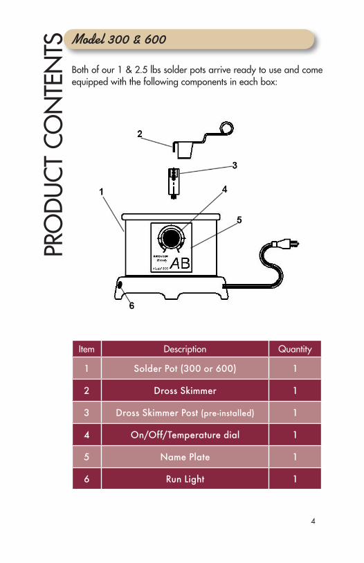
1 Solder Pot (300 or 600) 1
2 Dross Skimmer 1
3 Dross Skimmer Post (pre-installed) 1
4 On/Off/Temperature dial 1
5 Name Plate 1
6 Run Light 1
PRO
DU
CT
CON
TEN
TSBoth of our 1 & 2.5 lbs solder pots arrive ready to use and come equipped with the following components in each box:
Model 300 & 600
www.americanbeautytools.com5
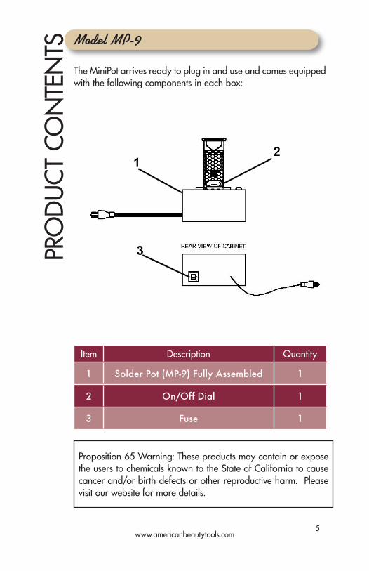
Model MP-9
The MiniPot arrives ready to plug in and use and comes equipped with the following components in each box:
PRO
DU
CT
CON
TEN
TS
Item Description Quantity
1 Solder Pot (MP-9) Fully Assembled 1
2 On/Off Dial 1
3 Fuse 1
Proposition 65 Warning: These products may contain or expose the users to chemicals known to the State of California to cause cancer and/or birth defects or other reproductive harm. Please visit our website for more details.
6
SAFE
TYSolder pots contain molten solder which is extremely hot. Operators of this product should be made aware of and fully understand all of the warnings as they relate to the operation or use of this device. Failure to observe the following safety instruction could result in serious injury.
Safety - Personal
• Only use the solder pot for its intended use as outlined in the introduction of this manual.
• Always wear Personal Protective Equipment (PPE) when operating your solder pot. This includes safety glasses, protective gloves, and sleeves (if necessary) to cover your body.
• Do not operate solder pot while under the influence of alcohol or drugs.
Safety - Workspace
• Always operate the solder pot in a well ventilated area. Some solders and fluxes release fumes that can be harmful. Proper attention should be given to these materials and the ventilation required to exhaust these fumes.
• Do not operate the solder pot in the presence of water and/or combustible & heat sensitive materials.
• Never leave a solder pot unattended unless it is unplugged and completely cooled down. Note: When cooling, solder will solidify on surface, but will remain molten beneath the surface for an extended period of time.
• Be sure to properly label work area when in use to identify the dangers of a hot solder pot.
www.americanbeautytools.com7
Safety - Device
• American Beauty solder pots are available in both a low voltage (110-120VAC) and high voltage (220-240VAC) version. Please consult your cord label to determine what version you have purchased and ensure your solder pot is properly plugged in to the corresponding outlet.
• When in operation, a solder pot gets extremely hot to the touch. After a period of time, this can also include the adjustment knob. Extreme caution should be used when touching any part of the solder pot. Do not pick up pot at any time during operation.
• Always ensure that the solder pot has been properly turned off at the completion of its use:
• Models 300 & 600 – these models use a bi-metal thermostat to control temperature and should be turned to the lowest setting and unplugged to ensure they are “off”.
• MP-9 – this model’s temperature control comes equipped with a “positive off” feature that can be both heard and felt. The unit may be unplugged as well as a secondary caution.
• Do not attempt to operate the solder pot with a frayed or damaged cord.
• Do not operate the solder pot with the base plate removed, this could expose the operator to an electrical shock.
• Do not attempt to remove the protective circuitry.
• Never attempt to perform routine maintenance, repairs, diagnostics, or install replacements while unit is plugged in.
• Repairs should only be performed by a qualified technician familiar with the product.
SAFE
TY
8
SET-
UP
& O
PERA
TIO
N Selecting a Location
We have created a checklist of considerations to guide you in selecting a suitable location for your solder pot. Choosing a good location to station your solder pot is the first step to operating your solder pot safely and efficiently.
• Area is well ventilated
• Surface is both flat and level
• Surface is both chemically and thermally resistant
• Area is away from high volume foot traffic zones
• Area is free from excess clutter
• Workspace is not in the direct path of airflow from AC or furnace vent
• Workspace is preferably on an inside wall, or at-least away from windows
• Workspace has access to a properly grounded outlet whose output voltage matches that of your tool. (110-120VAC or 220-240VAC)
• Workspace has adequate space that allows the power cord to hang freely
Following these basic steps should ensure a suitably safe and efficient location for the operation of your solder pot.
Charging the Solder Pot
“Charging” a solder pot is the common industry term that describes the process of adding solder to the solder pot for the first time. Follow these easy steps to get your pot ready for every-day usage.
1. Prepare solder ~ While many forms of solder can be used for the charging of your pot, we recommend bar solder, cut into 1” pieces.
www.americanbeautytools.com9
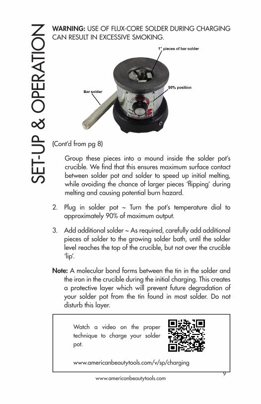
(Cont’d from pg 8)
Group these pieces into a mound inside the solder pot’s crucible. We find that this ensures maximum surface contact between solder pot and solder to speed up initial melting, while avoiding the chance of larger pieces ‘flipping’ during melting and causing potential burn hazard.
2. Plug in solder pot ~ Turn the pot’s temperature dial to approximately 90% of maximum output.
3. Add additional solder ~ As required, carefully add additional pieces of solder to the growing solder bath, until the solder level reaches the top of the crucible, but not over the crucible ‘lip’.
Note: A molecular bond forms between the tin in the solder and the iron in the crucible during the initial charging. This creates a protective layer which will prevent future degradation of your solder pot from the tin found in most solder. Do not disturb this layer.
WARNING: USE OF FLUX-CORE SOLDER DURING CHARGING CAN RESULT IN EXCESSIVE SMOKING.
SET-
UP
& O
PERA
TIO
N
Watch a video on the proper technique to charge your solder pot.
www.americanbeautytools.com/v/sp/charging
10
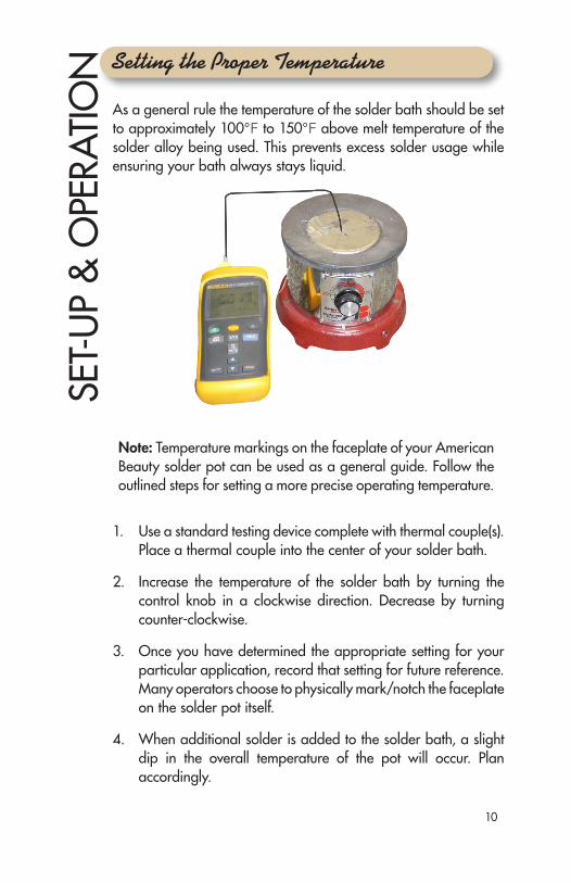
As a general rule the temperature of the solder bath should be set to approximately 100°F to 150°F above melt temperature of the solder alloy being used. This prevents excess solder usage while ensuring your bath always stays liquid.
1. Use a standard testing device complete with thermal couple(s). Place a thermal couple into the center of your solder bath.
2. Increase the temperature of the solder bath by turning the control knob in a clockwise direction. Decrease by turning counter-clockwise.
3. Once you have determined the appropriate setting for your particular application, record that setting for future reference. Many operators choose to physically mark/notch the faceplate on the solder pot itself.
4. When additional solder is added to the solder bath, a slight dip in the overall temperature of the pot will occur. Plan accordingly.
Setting the Proper TemperatureSE
T-U
P &
OPE
RATI
ON
Note: Temperature markings on the faceplate of your American Beauty solder pot can be used as a general guide. Follow the outlined steps for setting a more precise operating temperature.
www.americanbeautytools.com11
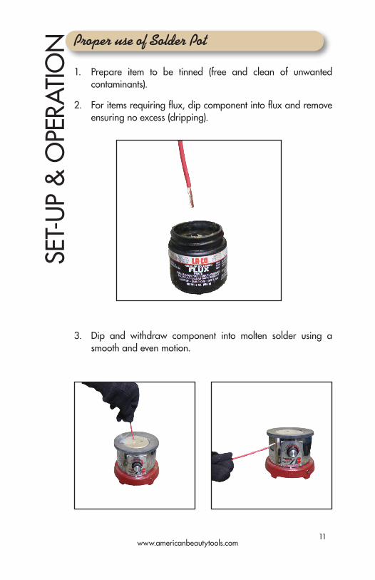
1. Prepare item to be tinned (free and clean of unwanted contaminants).
2. For items requiring flux, dip component into flux and remove ensuring no excess (dripping).
3. Dip and withdraw component into molten solder using a smooth and even motion.
Proper use of Solder PotSE
T-U
P &
OPE
RATI
ON
12
MA
INTE
NA
NCE
& C
ARE
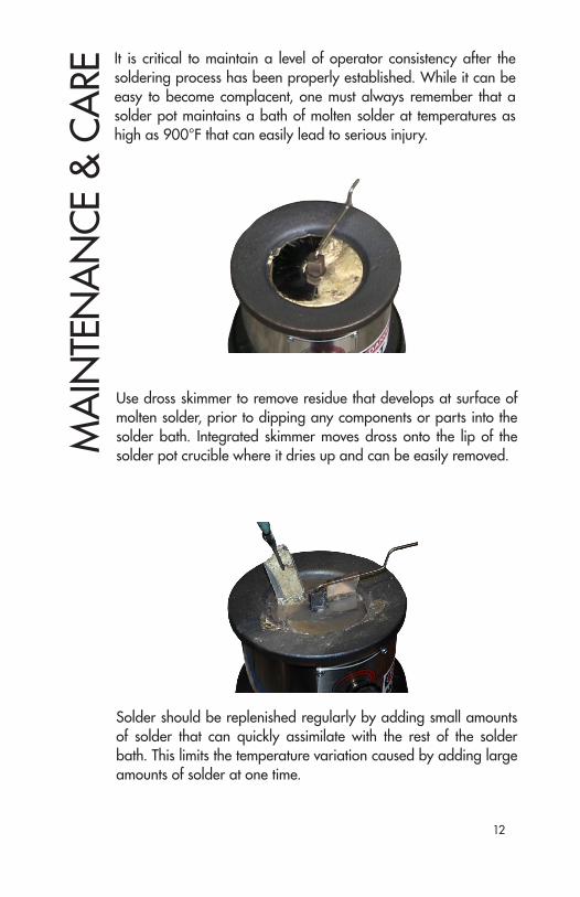
It is critical to maintain a level of operator consistency after the soldering process has been properly established. While it can be easy to become complacent, one must always remember that a solder pot maintains a bath of molten solder at temperatures as high as 900°F that can easily lead to serious injury.
Use dross skimmer to remove residue that develops at surface of molten solder, prior to dipping any components or parts into the solder bath. Integrated skimmer moves dross onto the lip of the solder pot crucible where it dries up and can be easily removed.
Solder should be replenished regularly by adding small amounts of solder that can quickly assimilate with the rest of the solder bath. This limits the temperature variation caused by adding large amounts of solder at one time.
www.americanbeautytools.com13
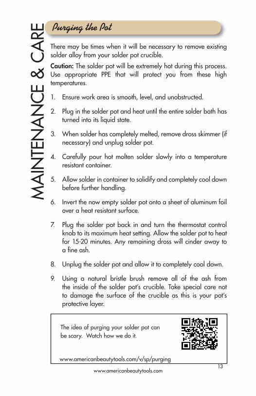
Caution: The solder pot will be extremely hot during this process. Use appropriate PPE that will protect you from these high temperatures.
1. Ensure work area is smooth, level, and unobstructed.
2. Plug in the solder pot and heat until the entire solder bath has turned into its liquid state.
3. When solder has completely melted, remove dross skimmer (if necessary) and unplug solder pot.
4. Carefully pour hot molten solder slowly into a temperature resistant container.
5. Allow solder in container to solidify and completely cool down before further handling.
6. Invert the now empty solder pot onto a sheet of aluminum foil over a heat resistant surface.
7. Plug the solder pot back in and turn the thermostat control knob to its maximum heat setting. Allow the solder pot to heat for 15-20 minutes. Any remaining dross will cinder away to a fine ash.
8. Unplug the solder pot and allow it to completely cool down.
9. Using a natural bristle brush remove all of the ash from the inside of the solder pot’s crucible. Take special care not to damage the surface of the crucible as this is your pot’s protective layer.
There may be times when it will be necessary to remove existing solder alloy from your solder pot crucible.
MA
INTE
NA
NCE
& C
ARE Purging the Pot
The idea of purging your solder pot can be scary. Watch how we do it.
www.americanbeautytools.com/v/sp/purging
14
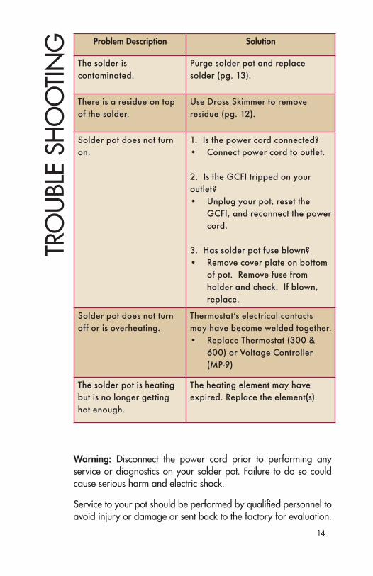
Problem Description Solution
The solder is contaminated.
Purge solder pot and replace solder (pg. 13).
There is a residue on top of the solder.
Use Dross Skimmer to remove residue (pg. 12).
Solder pot does not turn on.
1. Is the power cord connected?• Connect power cord to outlet.
2. Is the GCFI tripped on your outlet?• Unplug your pot, reset the
GCFI, and reconnect the power cord.
3. Has solder pot fuse blown?• Remove cover plate on bottom
of pot. Remove fuse from holder and check. If blown, replace.
Solder pot does not turn off or is overheating.
Thermostat’s electrical contacts may have become welded together. • Replace Thermostat (300 &
600) or Voltage Controller (MP-9)
The solder pot is heating but is no longer getting hot enough.
The heating element may have expired. Replace the element(s).
TRO
UBL
E SH
OO
TIN
G
Warning: Disconnect the power cord prior to performing any service or diagnostics on your solder pot. Failure to do so could cause serious harm and electric shock.
Service to your pot should be performed by qualified personnel to avoid injury or damage or sent back to the factory for evaluation.
www.americanbeautytools.com15
REP
LACE
MEN
T PA
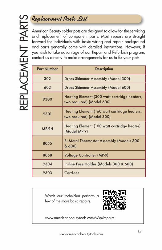
RTS Replacement Parts List
American Beauty solder pots are designed to allow for the servicing and replacement of component parts. Most repairs are straight forward for individuals with basic wiring and repair background and parts generally come with detailed instructions. However, if you wish to take advantage of our Repair and Refurbish program, contact us directly to make arrangements for us to fix your pots.
Part Number Description
302 Dross Skimmer Assembly (Model 300)
602 Dross Skimmer Assembly (Model 600)
9300Heating Element (300 watt cartridge heaters, two required) (Model 600)
9301Heating Element (160 watt cartridge heaters, two required) (Model 300)
MP-9HHeating Element (100 watt cartridge heater) (Model MP-9)
8055Bi-Metal Thermostat Assembly (Models 300 & 600)
8058 Voltage Controller (MP-9)
9304 In-line Fuse Holder (Models 300 & 600)
9303 Cord-set
Watch our technician perform a few of the more basic repairs.
www.americanbeautytools.com/v/sp/repairs
16
Warranty DetailsW
ARR
AN
TY &
SER
VICE
DET
AILS
Repair Service
American Beauty tools are warrantied to be free from defects in material and workmanship as outlined below. No warranty is made with respect to products which have been altered, subjected to abuse or improperly used.
Consumable Parts - NOT COVERED
Items include such parts as Soldering Iron Tips, Desoldering Braid, Resistance Soldering Elements and Electrodes, etc.
Serviceable Parts - 90-DAY PERIOD
Items include such parts as are Heating Elements, Thermostats, Voltage Controllers, Cord-sets, etc. It is the customer’s responsibility to make themselves aware of proper operating parameters, that when not followed, can greatly reduce the life-span of this type of part.
Standard American Beauty Products - 3-YR PERIOD
These items include all American Beauty soldering tools that don’t fall into the two categories highlighted above.
Complete warranty details can be located on our company website at www.americanbeautytools.com/warranty
Eventually even the toughest soldering tools require minor repair work. We have expanded our internal repair department and reassigned our most experienced technicians to work on repairs. We implemented customized software to ensure accurate and timely processing of all returned products. Save yourself unnecessary downtime and aggravation by taking advantage of American Beauty’s world-class repair and refurbishment service. Contact us today to make arrangements, or visit www.americanbeautytools.com/repair