Embed Size (px)
Citation preview
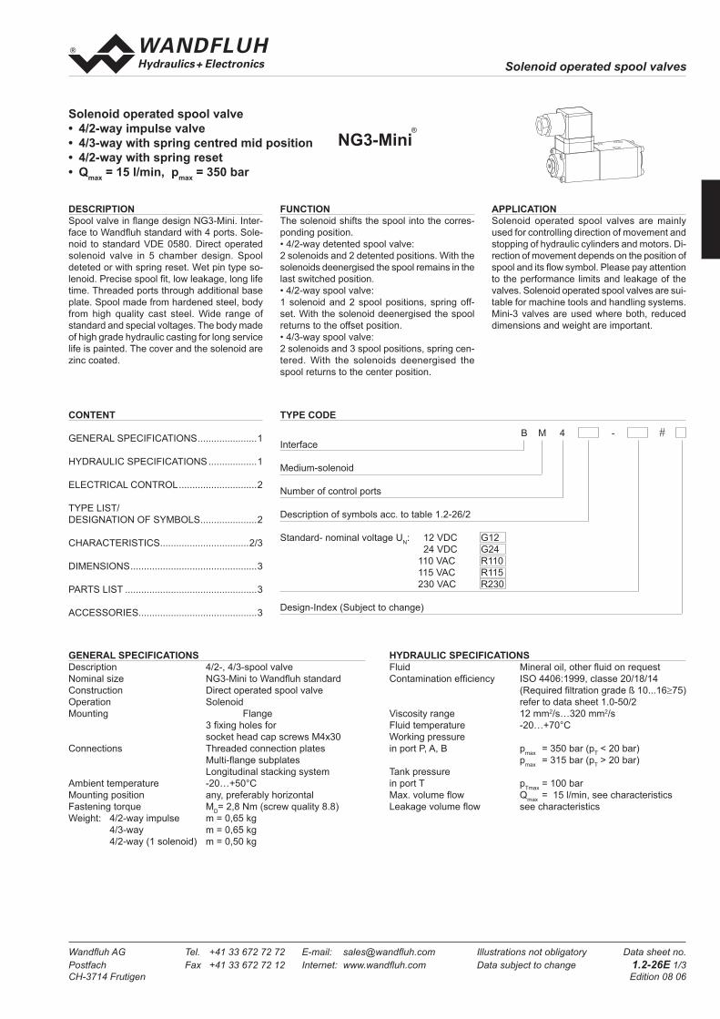
Solenoid operated spool valves
Wandfl uh AG Tel. +41 33 672 72 72 E-mail: sales@wandfl uh.com Illustrations not obligatory Data sheet no.
Postfach Fax +41 33 672 72 12 Internet: www.wandfl uh.com Data subject to change 1.2-26E 1/3
CH-3714 Frutigen Edition 08 06
Solenoid operated spool valve
• 4/2-way impulse valve
• 4/3-way with spring centred mid position
• 4/2-way with spring reset
• Qmax
= 15 l/min, pmax
= 350 bar
B M 4 - #
Interface
Medium-solenoid
Number of control ports
Description of symbols acc. to table 1.2-26/2
Standard- nominal voltage UN: 12 VDC G12
24 VDC G24
110 VAC R110
115 VAC R115
230 VAC R230
Design-Index (Subject to change)
TYPE CODE
DESCRIPTION
Spool valve in fl ange design NG3-Mini. Inter-
face to Wandfl uh standard with 4 ports. Sole-
noid to standard VDE 0580. Direct operated
solenoid valve in 5 chamber design. Spool
deteted or with spring reset. Wet pin type so-
lenoid. Precise spool fi t, low leakage, long life
time. Threaded ports through additional base
plate. Spool made from hardened steel, body
from high quality cast steel. Wide range of
standard and special voltages. The body made
of high grade hydraulic casting for long service
life is painted. The cover and the solenoid are
zinc coated.
FUNCTION
The solenoid shifts the spool into the corres-
ponding position.
• 4/2-way detented spool valve:
2 solenoids and 2 detented positions. With the
solenoids deenergised the spool remains in the
last switched position.
• 4/2-way spool valve:
1 solenoid and 2 spool positions, spring off-
set. With the solenoid deenergised the spool
returns to the offset position.
• 4/3-way spool valve:
2 solenoids and 3 spool positions, spring cen-
tered. With the solenoids deenergised the
spool returns to the center position.
APPLICATION
Solenoid operated spool valves are mainly
used for controlling direction of movement and
stopping of hydraulic cylinders and motors. Di-
rection of movement depends on the position of
spool and its fl ow symbol. Please pay attention
to the performance limits and leakage of the
valves. Solenoid operated spool valves are sui-
table for machine tools and handling systems.
Mini-3 valves are used where both, reduced
dimensions and weight are important.
CONTENT
GENERAL SPECIFICATIONS ......................1
HYDRAULIC SPECIFICATIONS ..................1
ELECTRICAL CONTROL .............................2
TYPE LIST/
DESIGNATION OF SYMBOLS .....................2
CHARACTERISTICS .................................2/3
DIMENSIONS ...............................................3
PARTS LIST .................................................3
ACCESSORIES............................................3
GENERAL SPECIFICATIONS
Description 4/2-, 4/3-spool valve
Nominal size NG3-Mini to Wandfl uh standard
Construction Direct operated spool valve
Operation Solenoid
Mounting Flange
3 fi xing holes for
socket head cap screws M4x30
Connections Threaded connection plates
Multi-fl ange subplates
Longitudinal stacking system
Ambient temperature -20…+50°C
Mounting position any, preferably horizontal
Fastening torque MD= 2,8 Nm (screw quality 8.8)
Weight: 4/2-way impulse m = 0,65 kg
4/3-way m = 0,65 kg
4/2-way (1 solenoid) m = 0,50 kg
HYDRAULIC SPECIFICATIONS
Fluid Mineral oil, other fl uid on request
Contamination effi ciency ISO 4406:1999, classe 20/18/14
(Required fi ltration grade ß 10...16≥75)
refer to data sheet 1.0-50/2
Viscosity range 12 mm2/s…320 mm2/s
Fluid temperature -20…+70°C
Working pressure
in port P, A, B pmax
= 350 bar (pT < 20 bar)
pmax
= 315 bar (pT > 20 bar)
Tank pressure
in port T pTmax
= 100 bar
Max. volume fl ow Qmax
= 15 l/min, see characteristics
Leakage volume fl ow see characteristics
NG3-Mini®

Solenoid operated spool valves
Wandfl uh AG Tel. +41 33 672 72 72 E-mail: sales@wandfl uh.com Illustrations not obligatory Data sheet no.
Postfach Fax +41 33 672 72 12 Internet: www.wandfl uh.com Data subject to change 1.2-26E 2/3
CH-3714 Frutigen Edition 08 06
ELECTRICAL CONTROL
Voltage tolerance ±10% of nominal voltage
Protection class IP 65 to EN 60529
Relative duty factor 100% DF (see data sheet 1.1-430)
Switching cycles 15'000/h
Operating life 107 (number of switching cycles, theoretically)
Connection/Power supply Over device plug connection to
EN175301-803 (DIN 43650)
ISO4400, form A, (2P+E),
other connections on request.
Solenoid connection: SIN29V (data sheet 1.1-80)
Construction Solenoid, wet pin push type, pressure tight
Standard-nominal voltage UN = 12 VDC
UN = 24 VDC
UN = 110 VAC∗
UN = 115 VAC∗
UN
= 230 VAC∗
AC = 50 bis 60 Hz
∗ Rectifi er integrated in the plug,
other nominal voltages and nominal
performances on request
TYPE LIST / DESIGNATION OF SYMBOLS
4/3-way valve spring centered
4/2-way valve impulse 4/2-way valve with spring reset Transitional functions
operation A-side operation B-side
CHARACTERSISTICS Oilviscosity υ = 30 mm2/s
p = f (Q) Performance limits with standard voltage -10% QL = f (p) Leakage volume fl ow characteristics
per control edge
Leakage envelope J30/Z30/D31/D32/D34/D35
Leakage envelope D33
0 150
Q [l/m in]
K0261
p [bar]
50100150200250300350
2 4 6 8 10 12 14
Z31/D31
Z34/D34Z35/D35
Z32/D32Z33/D33
J30 Z30
K0263
a b
BA
P T
a b
BA
P T
o
a b
BA
P T
o
a b
BA
P T
o
a b
BA
P T
o
a b
BA
P T
a b
BA
P T
ab
BA
P T
a b
BA
P T
ab
BA
P T
ab
BA
P T
a b
BA
P T
a b
BA
P T
ab
BA
P T
a b
BA
P T
ab
BA
P T
ab
BA
P T
J30
D31
D32
D33
D34
D35
Z30a
Z31a
Z32a
Z33a
Z34a
Z35a
Z30b
Z31b
Z32b
Z33b
Z34b
Z35b
a b
BA
P T
o
Solenoid operated spool valves
Wandfl uh AG Tel. +41 33 672 72 72 E-mail: sales@wandfl uh.com Illustrations not obligatory Data sheet no.
Postfach Fax +41 33 672 72 12 Internet: www.wandfl uh.com Data subject to change 1.2-26E 3/3
CH-3714 Frutigen Edition 08 06
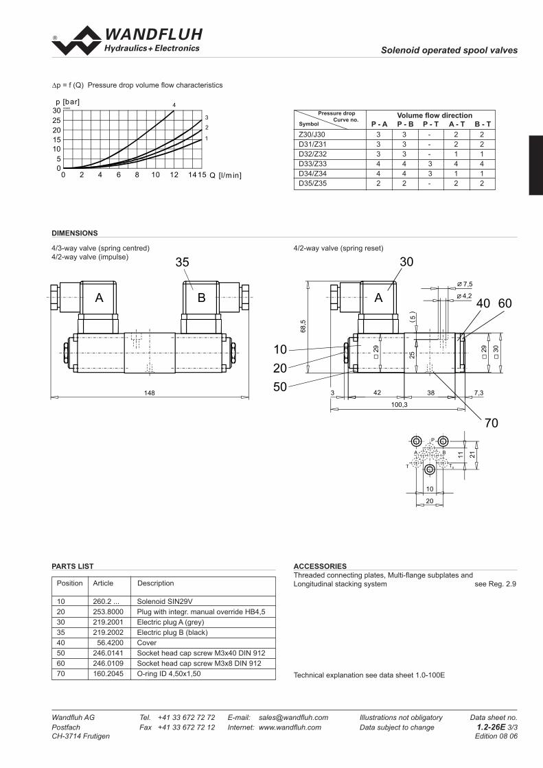
∆p = f (Q) Pressure drop volume fl ow characteristics
ACCESSORIES
Threaded connecting plates, Multi-fl ange subplates and
Longitudinal stacking system see Reg. 2.9
DIMENSIONS
4/3-way valve (spring centred)
4/2-way valve (impulse)
4/2-way valve (spring reset)
Volume fl ow direction
P - A P - B P - T A - T B - T
Z30/J30 3 3 - 2 2
D31/Z31 3 3 - 2 2
D32/Z32 3 3 - 1 1
D33/Z33 4 4 3 4 4
D34/Z34 4 4 3 1 1
D35/Z35 2 2 - 2 2
Pressure drop
Curve no.Symbol
0 150
Q [l/m in]
K0262
p [bar]
2 4 6 8 10 12 14
1
2
3
4
5
10
15
20
25
30
Technical explanation see data sheet 1.0-100E
PARTS LIST
Position Article Description
10 260.2 ... Solenoid SIN29V
20 253.8000 Plug with integr. manual override HB4,5
30 219.2001 Electric plug A (grey)
35 219.2002 Electric plug B (black)
40 56.4200 Cover
50 246.0141 Socket head cap screw M3x40 DIN 912
60 246.0109 Socket head cap screw M3x8 DIN 912
70 160.2045 O-ring ID 4,50x1,50
10
20
50
30
40 60
70
A
29
30
29
68,5
3 42 38 7,3
100,325
5()
4,2
7,5
35
A B
148
A B
P
T T0
10
20
11
21

Solenoid operated spool valves
Wandfl uh AG Tel. +41 33 672 72 72 E-mail: sales@wandfl uh.com Illustrations not obligatory Data sheet no.
Postfach Fax +41 33 672 72 12 Internet: www.wandfl uh.com Data subject to change 1.2-33E 1/4
CH-3714 Frutigen Edition 14 10
Solenoid operated spool valve
• 4/2-way impulse valve
• 4/3-way with spring centred mid position
• 4/2-way with spring reset
• Qmax
= 30 l/min, pmax
= 350 bar
GENERAL SPECIFICATIONS
Description 4/2-, 4/3-spool valve
Nominal size NG4-Mini to Wandfl uh standard
Construction Direct operated spool valve
Operation Solenoid
Mounting Flange
3 fi xing holes for
socket head cap screws M5x40
Connections Threaded connection plates
Multi-fl ange subplates
Longitudinal stacking system
APPLICATION
Solenoid operated spool valves are mainly
used for controlling direction of movement and
stopping of hydraulic cylinders and motors. Di-
rection of movement depends on the position of
spool and its fl ow symbol. Please pay attention
to the performance limits and leakage of the
valves. Solenoid operated spool valves are sui-
table for machine tools and handling systems.
Mini-4 valves are used where both, reduced
dimensions and weight are important.
DESCRIPTION
Spool valve in fl ange design NG4-Mini. Inter-
face to Wandfl uh standard with 4 ports. Soleno-
id to standard VDE 0580. Direct operated sole-
noid valve in 5 chamber design. Spool deteted
or with spring reset. Wet pin type solenoid.
Precise spool fi t, low leakage, long life time.
Spool made from hardened steel. Wide range
of standard and special voltages. Two basic
versions available (Economy and Medium). The
body made of high grade hydraulic casting for
long service life is painted. The armature tube
and the plug crew are zinc coated. The solenoid
coil is nickel-/chromium-coated.
FUNCTION
The solenoid shifts the spool into the corres-
ponding position.
• 4/2-way detented spool valve:
2 solenoids and 2 detented positions. With the
solenoids deenergised the spool remains in the
last switched position.
• 4/2-way spool valve:
1 solenoid and 2 spool positions, spring off-
set. With the solenoid deenergised the spool
returns to the offset position.
• 4/3-way spool valve:
2 solenoids and 3 spool positions, spring cen-
tered. With the solenoids deenergised the
spool returns to the center position.
NG4-Mini®
Ambient temperature -20…+70 °C (slip-on coil«V»)
if > +50 °C, then
voltage tolerance 0 / -10%
-20…+70 °C (slip-on coil «N»)
Mounting position any, preferably horizontal
Fastening torque MD= 5,5 Nm (screw quality 8.8)
For fi xing screws
MD= 5 Nm for Knurled nut
W D F A04 - - - / - #
Spool valve direct operated
Economy-slip-on coil E
Medium-slip-on coil M
Flange construction
Mounting interface acc. to Wandfl uh standard, NG4-Mini
Description of symbols acc. to table 1.2-33/2
Spool specifi cation Standard
Low Leakage 1/x (only Economy)
Standard-nominal voltage UN 12 VDC G12
24 VDC G24
115 VAC R115
230 VAC R230
without solenoid coil X5
Slip-on coil Metal housing round with one-sided collar V
Metal housing square with one-sided collar N* (only Medium)
Electric connection Connector socket EN 175301 - 803 / ISO4400 D
Connector socket AMP Junior-Timer J (only for UN ≤ 75 VDC)
Connector Deutsch DT04 - 2P G (only for UN ≤ 75 VDC)
Sealing material NBR
FKM (Viton) D1
Manual override Integrated
Push-button HF1
Spindle HS1
Design-Index (Subject to change)
* Only available in conjunction with other nominal voltages and connection versions. (See data sheet 1.1-175)
TYPE CODE

Solenoid operated spool valves
Wandfl uh AG Tel. +41 33 672 72 72 E-mail: sales@wandfl uh.com Illustrations not obligatory Data sheet no.
Postfach Fax +41 33 672 72 12 Internet: www.wandfl uh.com Data subject to change 1.2-33E 2/4
CH-3714 Frutigen Edition 14 10
ELECTRICAL CONTROL
Construction Solenoid, wet pin push type, pressure tight
Standard-nominal voltage UN = 12 VDC
UN = 24 VDC
UN = 115 VAC∗
UN
= 230 VAC∗
AC = 50 to 60 Hz
∗ Rectifi er integrated in the coil, other
nominal voltages and nominal
performances on request
Voltage tolerance ±10% of nominal voltage
Protection class Connection version
to EN 60 529 D: IP 65
J: IP 66 only for UN ≤ 75 VDC
G: IP 67 and 69K only for UN ≤ 75 VDC
Relative duty factor 100% DF (see data sheet 1.1-430)
Switching cycles 15 000/h
Operating life 107 (number of switching cycles, theoretically)
Connection/Power supply Over device plug connection
Coil versions:
Economy: V.E37 / 19 x 40 (data sheet 1.1-168)
Medium: V.E37 / 19 x 50 (data sheet 1.1-168)
Other electrical specifi cations see data sheet 1.1-168 (V)
1.1-175 (N)
TYPE LIST / DESIGNATION OF SYMBOLS
4/2-way valve impulse 4/2-way valve with spring reset Transitional functions
operation A-side operation B-side
4/3-way valve spring centered
MANUAL OVERRIDE
- Integrated (–) Actuation pin integrated in the armature tube.
- Push-button (HF1) integrated in the knurled nut.
Actuation by pressing the pin
- Spindle (HS1) integrated in the knurled nut.
Actuation by turning the spindle (infi nitely variable valve actuation)
HYDRAULIC SPECIFICATIONS
Fluid Mineral oil, other fl uid on request
Contamination effi ciency ISO 4406:1999, classe 20/18/14
(Required fi ltration grade ß 10…16≥75)
refer to data sheet 1.0-50/2
Viscosity range 12 mm2/s…320 mm2/s
Fluid temperature -20…+70°C
Working pressure
in port P, A, B pmax
= 350 bar (pT <20 bar)
pmax
= 315 bar (pT >20 bar)
Tank pressure
in port T pT max
= 100 bar
Max. volume fl ow Qmax
= 30 l/min, see characteristics
Leakage volume fl ow see characteristics
Weight Economy Medium
4/2-way impulse m = 1,1 kg m = 1,25 kg
4/3-way m = 1,1 kg m = 1,25 kg
4/2-way (1 solenoid) m = 0,83 kg m = 0,9 kg
a b
BA
P T
a b
BA
P T
o
a b
BA
P T
o
a b
BA
P T
o
a b
BA
P T
o
a b
BA
P T
a b
BA
P T
ab
BA
P T
a b
BA
P T
ab
BA
P T
ab
BA
P T
a b
BA
P T
a b
BA
P T
ab
BA
P T
a b
BA
P T
ab
BA
P T
ab
BA
P T
AB3
ACB
ADB
BEA
AFB
AGB
AB1
AC1
AD1
BE1
AF1
AG1
AB2
CB2
DB2
EA2
FB2
GB2
a b
BA
P T
o
NOTE!
The actuation of the manual override is possible up to a
tank pressure of:
40 bar Integrated (-)
40 bar Push-button (HF1)
100 bar Spindle (HS1)
Solenoid operated spool valves
Wandfl uh AG Tel. +41 33 672 72 72 E-mail: sales@wandfl uh.com Illustrations not obligatory Data sheet no.
Postfach Fax +41 33 672 72 12 Internet: www.wandfl uh.com Data subject to change 1.2-33E 3/4
CH-3714 Frutigen Edition 14 10
Volume fl ow direction
P - A P - B P - T A - T B - T
AB1 2 2 - 1 1
AB3 2 2 - 1 1
ACB 2 2 - 1 1
ADB 2 2 - 1 1
BEA 1 1 4 1 1
AFB 1 1 3 1 1
AGB 1 1 - 1 1
Volume fl ow direction
P - A P - B P - T A - T B - T
AB1 1 1 - 1 2
AB3 1 1 - 1 2
ADB 1 1 - 4 3
QL = f (p) Leakage volume fl ow characteristics per control edge
Pressure drop
Curve no.
Pressure drop
Curve no.
Symbol
Symbol
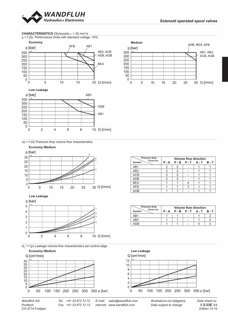
CHARACTERSISTICS Oilviscosity υ = 30 mm2/s
p = f (Q) Performance limits with standard voltage -10%
MediumEconomy
350300250200150100
500
AFB AB1
BEA
AB3, ACB
ADB, AGB
K1026
p [bar]
350300250200150100
500
AB1, AB3,
ACB, AGB
ADB, BEA, AFB
0 5 10 15 20 25 30
K1027
p [bar]
K1028
p [bar]
350300250200150100500
ADB
AB1
AB3
0 2 4 6 8 10
K1029
p [bar]
0 5 10 15 20 25 30
4
21
3
K1030
p [bar]
0 2 4 6 8 10
2
1
3
4
5
4
3
2
1
0
K1031
Q [cm3/min]
0 50 100 150 200 250 300 350
4035302520151050
K1032
Q [cm3/min]
0 50 100 150 200 250 300 350
12
10
8
6
4
2
0
∆p = f (Q) Pressure drop volume fl ow characteristics
Economy / Medium
Low Leakage
Economy / Medium
Low Leakage
Low Leakage

Solenoid operated spool valves
Wandfl uh AG Tel. +41 33 672 72 72 E-mail: sales@wandfl uh.com Illustrations not obligatory Data sheet no.
Postfach Fax +41 33 672 72 12 Internet: www.wandfl uh.com Data subject to change 1.2-33E 4/4
CH-3714 Frutigen Edition 14 10
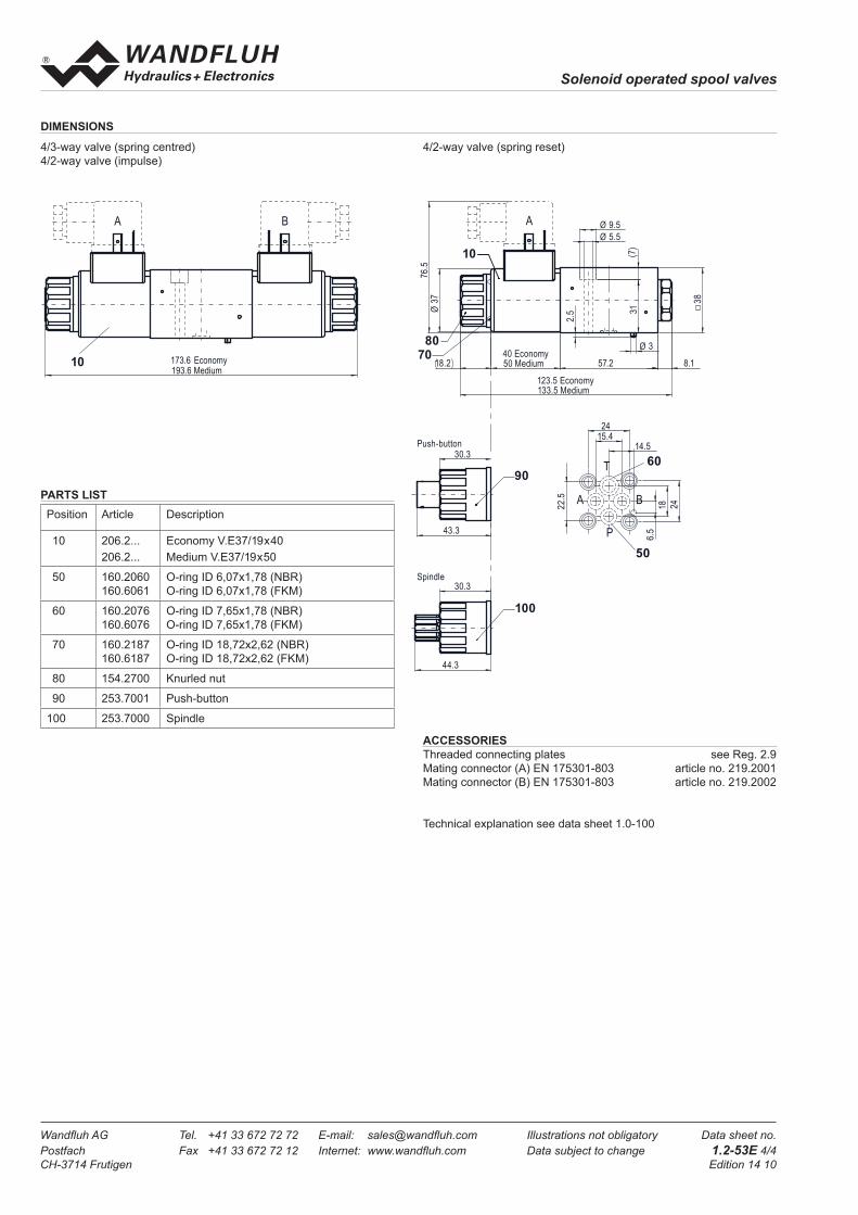
DIMENSIONS
4/3-way valve (spring centred)
4/2-way valve (impulse)
4/2-way valve (spring reset)
PARTS LIST
ACCESSORIES
Threaded connecting plates, Multi-fl ange subplates
and Longitudinal stacking system see Reg. 2.9
Mating connector (A) EN175301-803 article no. 219.2001
Mating connector (B) EN 175301-803 article no. 219.2002
Technical explanation see data sheet 1.0-100
Position Article Description
10 206.2...
206.2...
Economy V.E37/19x40
Medium V.E37/19x50
50 160.2052
160.6052
O-ring ID 5,28x1,78 (NBR)
O-ring ID 5,28x1,78 (FKM)
60 160.2187
160.6187
O-ring ID 18,72x2,62 (NBR)
O-ring ID 18,72x2,62 (FKM)
70 154.2700 Knurled nut
80 253.7001 Push-button
90 253.7000 Spindle
90
80
Push-button
Spindle
76.5
Ø 5.5 632
Ø 9.5
123.5 Economy133.5 Medium
57.2 8.1
38
Ø37
40 Economy50 Medium18.2
A
28
14
2714
P
A B
T T0
30.3
43.3
30.3
44.3
A B
193.6 Medium173.6 Economy
50
70
60
10

Solenoid operated spool valves
Wandfl uh AG Tel. +41 33 672 72 72 E-mail: sales@wandfl uh.com Illustrations not obligatory Data sheet no.
Postfach Fax +41 33 672 72 12 Internet: www.wandfl uh.com Data subject to change 1.2-53E 1/4
CH-3714 Frutigen Edition 14 10
Solenoid operated spool valve
• 4/2-way impulse valve
• 4/3-way with spring centred mid position
• 4/2-way with spring reset
• Qmax
= 30 l/min, pmax
= 350 bar
TYPE CODE
APPLICATION
Solenoid operated spool valves are mainly
used for controlling direction of movement and
stopping of hydraulic cylinders and motors.
Direction of movement depends on the posi-
tion of spool and its fl ow symbol. Please pay
attention to the performance limits and leakage
of the valves. Solenoid operated spool valves
are suitable for machine tools and handling sy-
stems. 4 valves are used where both, reduced
dimensions and weight are important.
DESCRIPTION
Spool valve in flange design NG4 to ISO
4401-02 with 4 ports. Solenoid to standard
VDE 0580. Direct operated solenoid valve in 5
chamber design. Spool deteted or with spring
reset. Wet pin type solenoid. Precise spool fi t,
low leakage, long life time. Spool made from
hardened steel. Wide range of standard and
special voltages. Two basic versions available
(Economy and Medium). The body made of
high grade hydraulic casting for long service
life is painted. The armature tube and the
plug crew are zinc coated. The solenoid coil is
nickel-/chromium-coated.
FUNCTION
The solenoid shifts the spool into the corres-
ponding position.
• 4/2-way detented spool valve:
2 solenoids and 2 detented positions. With the
solenoids deenergised the spool remains in the
last switched position.
• 4/2-way spool valve:
1 solenoid and 2 spool positions, spring off-
set. With the solenoid deenergised the spool
returns to the offset position.
• 4/3-way spool valve:
2 solenoids and 3 spool positions, spring cen-
tered. With the solenoids deenergised the
spool returns to the center position.
NG4ISO 4401-02
GENERAL SPECIFICATIONS
Description 4/2-, 4/3-spool valve
Nominal size NG4 to ISO 4401-02
Construction Direct operated spool valve
Operation Solenoid
Mounting Flange
4 fi xing holes for
socket head cap screws M5x40
Connections Threaded connection plates
Multi-fl ange subplates
Longitudinal stacking system
Ambient temperature -20…+70 °C (slip-on coil«V»)
if > +50 °C, then
voltage tolerance 0 / -10%
-20…+70 °C (slip-on coil «N»)
Mounting position any, preferably horizontal
Fastening torque MD= 5,5 Nm (screw quality 8.8)
For fi xing screws
MD= 5 Nm for Knurled nut
W D F B04 - - - / - #
Spool valve direct operated
Economy-slip-on coil E
Medium-slip-on coil M
Flange construction
International standard interface ISO, nominal size 4
Description of symbols acc. to table 1.2-53/2
Spool specifi cation Standard
Low Leakage 1/x (only Economy)
Standard-nominal voltage UN 12 VDC G12
24 VDC G24
115 VAC R115
230 VAC R230
without solenoid coil X5
Slip-on coil Metal housing round with one-sided collar V
Metal housing square with one-sided collar N* (only Medium)
Electric connection Connector socket EN 175301 - 803 / ISO4400 D
Connector socket AMP Junior-Timer J (only for UN ≤ 75 VDC)
Connector Deutsch DT04 - 2P G (only for UN ≤ 75 VDC)
Sealing material NBR
FKM (Viton) D1
Manual override Integrated
Push-button HF1
Spindle HS1
Design-Index (Subject to change)
* Only available in conjunction with other nominal voltages and connection versions. (See data sheet 1.1-175)

Solenoid operated spool valves
Wandfl uh AG Tel. +41 33 672 72 72 E-mail: sales@wandfl uh.com Illustrations not obligatory Data sheet no.
Postfach Fax +41 33 672 72 12 Internet: www.wandfl uh.com Data subject to change 1.2-53E 2/4
CH-3714 Frutigen Edition 14 10
TYPE LIST / DESIGNATION OF SYMBOLS
4/3-way valve spring centered
4/2-way valve impulse 4/2-way valve with spring reset Transitional functions
operation A-side operation B-side
ELECTRICAL CONTROL
Construction Solenoid, wet pin push type, pressure tight
Standard-nominal voltage UN = 12 VDC
UN = 24 VDC
UN = 115 VAC∗
UN
= 230 VAC∗
AC = 50 to 60 Hz
∗ Rectifi er integrated in the coil, other
nominal voltages and nominal
performances on request
Voltage tolerance ±10% of nominal voltage
Protection class Connection version
to EN 60 529 D: IP 65
J: IP 66 only for UN ≤ 75 VDC
G: IP 67 and 69K only for UN ≤ 75 VDC
Relative duty factor 100% DF (see data sheet 1.1-430)
Switching cycles 15 000/h
Operating life 107 (number of switching cycles, theoretically)
Connection/Power supply Over device plug connection
Coil versions:
Economy: V.E37 / 19 x 40 (data sheet 1.1-168)
Medium: V.E37 / 19 x 50 (data sheet 1.1-168)
Other electrical specifi cations see data sheet 1.1-168 (V)
1.1-175 (N)
MANUAL OVERRIDE
- Integrated (–) Actuation pin integrated in the armature tube.
- Push-button (HF1) integrated in the knurled nut.
Actuation by pressing the pin
- Spindle (HS1) integrated in the knurled nut.
Actuation by turning the spindle (infi nitely variable valve actuation)
HYDRAULIC SPECIFICATIONS
Fluid Mineral oil, other fl uid on request
Contamination effi ciency ISO 4406:1999, classe 20/18/14
(Required fi ltration grade ß 10…16≥75)
refer to data sheet 1.0-50/2
Viscosity range 12 mm2/s…320 mm2/s
Fluid temperature -20…+70°C
Working pressure
in port P, A, B pmax
= 350 bar
Tank pressure
in port T pT max
= 100 bar
Max. volume fl ow Qmax
= 30 l/min, see characteristics
Leakage volume fl ow see characteristics
Weight Economy Medium
4/2-way impulse m = 1,1 kg m = 1,25 kg
4/3-way m = 1,1 kg m = 1,25 kg
4/2-way (1 solenoid) m = 0,83 kg m = 0,9 kg
a b
BA
P T
a b
BA
P T
o
a b
BA
P T
o
a b
BA
P T
o
a b
BA
P T
o
a b
BA
P T
a b
BA
P T
ab
BA
P T
a b
BA
P T
ab
BA
P T
ab
BA
P T
a b
BA
P T
a b
BA
P T
ab
BA
P T
a b
BA
P T
ab
BA
P T
ab
BA
P T
AB3
ACB
ADB
BEA
AFB
AGB
AB1
AC1
AD1
BE1
AF1
AG1
AB2
CB2
DB2
EA2
FB2
GB2
a b
BA
P T
o
NOTE!
The actuation of the manual override is possible up to a
tank pressure of:
40 bar Integrated (-)
40 bar Push-button (HF1)
100 bar Spindle (HS1)

Solenoid operated spool valves
Wandfl uh AG Tel. +41 33 672 72 72 E-mail: sales@wandfl uh.com Illustrations not obligatory Data sheet no.
Postfach Fax +41 33 672 72 12 Internet: www.wandfl uh.com Data subject to change 1.2-53E 3/4
CH-3714 Frutigen Edition 14 10
Volume fl ow direction
P - A P - B P - T A - T B - T
AB1 2 2 - 1 1
AB3 2 2 - 1 1
ACB 2 2 - 1 1
ADB 2 2 - 1 1
BEA 2 2 4 2 2
AFB 1 1 3 3 3
AGB 3 3 - 1 1
Volume fl ow direction
P - A P - B P - T A - T B - T
AB1 1 1 - 1 1
AB3 1 1 - 2 2
ADB 1 1 - 1 1
∆p = f (Q) Pressure drop volume fl ow characteristics
QL = f (p) Leakage volume fl ow characteristics per control edge
Pressure drop
Curve no.
Pressure drop
Curve no.
Symbol
Symbol
CHARACTERSISTICS Oilviscosity υ = 30 mm2/s
p = f (Q) Performance limits with standard voltage -10%
Medium
Low Leakage
Economy
Low Leakage
Economy / Medium
Low Leakage
Economy / Medium
ADB
350300250200150100
500
BEA
AFB AB1AB3
ACB
AGB
0 5 10 15 20 Q [l/min]
p [bar]K1118
350300250200150100500
ADB
BEAAB1
AB3
ACB
AFB
AGB
0 5 10 15 20 25 30 Q [l/min]
p [bar]K1119
350300250200150100500
AB1
AB3
ADB
0 2 4 6 8 10 Q [l/min]
p [bar]K1120
30
25
20
15
10
5
00 5 10 15 20 25 30 Q [l/min]
p [bar]K1121
3
1
2
4
2017.5
1512.5
107.5
52.5
00 2 4 6 8 10 12 14 16 18 20 Q [l/min]
p [bar]K1122
2
1
0 50 100 150 200 250 300 350
4035302520151050
[cm3 /min]
K1033
0 50 100 150 200 250 300 350
[cm3 /min]
12
10
8
6
4
2
0
K1034
Solenoid operated spool valves
Wandfl uh AG Tel. +41 33 672 72 72 E-mail: sales@wandfl uh.com Illustrations not obligatory Data sheet no.
Postfach Fax +41 33 672 72 12 Internet: www.wandfl uh.com Data subject to change 1.2-53E 4/4
CH-3714 Frutigen Edition 14 10
DIMENSIONS
4/3-way valve (spring centred)
4/2-way valve (impulse)
4/2-way valve (spring reset)
PARTS LIST
ACCESSORIES
Threaded connecting plates see Reg. 2.9
Mating connector (A) EN 175301-803 article no. 219.2001
Mating connector (B) EN 175301-803 article no. 219.2002
Technical explanation see data sheet 1.0-100
Position Article Description
10 206.2...
206.2...
Economy V.E37/19x40
Medium V.E37/19x50
50 160.2060
160.6061
O-ring ID 6,07x1,78 (NBR)
O-ring ID 6,07x1,78 (FKM)
60 160.2076
160.6076
O-ring ID 7,65x1,78 (NBR)
O-ring ID 7,65x1,78 (FKM)
70 160.2187
160.6187
O-ring ID 18,72x2,62 (NBR)
O-ring ID 18,72x2,62 (FKM)
80 154.2700 Knurled nut
90 253.7001 Push-button
100 253.7000 Spindle
76.5
Ø 9.5
Ø 5.5
31(7
)
123.5 Economy133.5 Medium
Ø37
57.2
38
8.140 Economy50 Medium18.2
Ø 3
2.5
A
10
80
70
30.3
43.3
90
Push-button
50
6.5
14.5
2415.4
1822.
5
24
T
A B
P
60
173.6 Economy193.6 Medium
A B
10
30.3
44.3
100
Spindle
Solenoid operated spool valves
Wandfl uh AG Tel. +41 33 672 72 72 E-mail: sales@wandfl uh.com Illustrations not obligatory Data sheet no.
Postfach Fax +41 33 672 72 12 Internet: www.wandfl uh.com Data subject to change 1.2-59E 1/4
CH-3714 Frutigen Edition 12 33
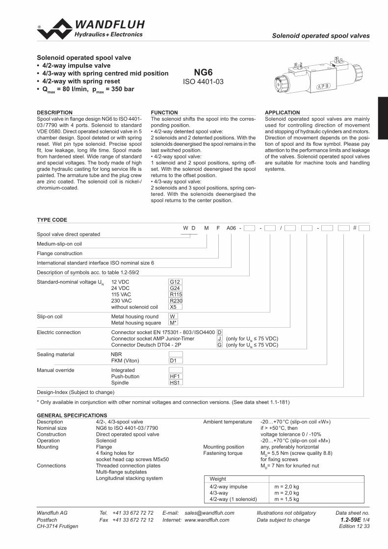
Solenoid operated spool valve
• 4/2-way impulse valve
• 4/3-way with spring centred mid position
• 4/2-way with spring reset
• Qmax
= 80 l/min, pmax
= 350 bar
GENERAL SPECIFICATIONS
Description 4/2-, 4/3-spool valve Ambient temperature -20…+70 °C (slip-on coil «W»)
Nominal size NG6 to ISO 4401-03 / 7790 if > +50 °C, then
Construction Direct operated spool valve voltage tolerance 0 / -10%
Operation Solenoid -20…+70 °C (slip-on coil «M»)
Mounting Flange Mounting position any, preferably horizontal
4 fi xing holes for Fastening torque MD= 5,5 Nm (screw quality 8.8)
socket head cap screws M5x50 for fi xing screws
Connections Threaded connection plates MD= 7 Nm for knurled nut
Multi-fl ange subplates
Longitudinal stacking system
APPLICATION
Solenoid operated spool valves are mainly
used for controlling direction of movement
and stopping of hydraulic cylinders and motors.
Direction of movement depends on the posi-
tion of spool and its fl ow symbol. Please pay
attention to the performance limits and leakage
of the valves. Solenoid operated spool valves
are suitable for machine tools and handling
systems.
DESCRIPTION
Spool valve in fl ange design NG6 to ISO 4401-
03 / 7790 with 4 ports. Solenoid to standard
VDE 0580. Direct operated solenoid valve in 5
chamber design. Spool deteted or with spring
reset. Wet pin type solenoid. Precise spool
fi t, low leakage, long life time. Spool made
from hardened steel. Wide range of standard
and special voltages. The body made of high
grade hydraulic casting for long service life is
painted. The armature tube and the plug crew
are zinc coated. The solenoid coil is nickel-/
chromium-coated.
FUNCTION
The solenoid shifts the spool into the corres-
ponding position.
• 4/2-way detented spool valve:
2 solenoids and 2 detented positions. With the
solenoids deenergised the spool remains in the
last switched position.
• 4/2-way spool valve:
1 solenoid and 2 spool positions, spring off-
set. With the solenoid deenergised the spool
returns to the offset position.
• 4/3-way spool valve:
2 solenoids and 3 spool positions, spring cen-
tered. With the solenoids deenergised the
spool returns to the center position.
NG6ISO 4401-03
W D M F A06 - - / - #
Spool valve direct operated
Medium-slip-on coil
Flange construction
International standard interface ISO nominal size 6
Description of symbols acc. to table 1.2-59/2
Standard-nominal voltage UN 12 VDC G12
24 VDC G24
115 VAC R115
230 VAC R230
without solenoid coil X5
Slip-on coil Metal housing round W
Metal housing square M*
Electric connection Connector socket EN 175301 - 803 / ISO4400 D
Connector socket AMP Junior-Timer J (only for UN ≤ 75 VDC)
Connector Deutsch DT04 - 2P G (only for UN ≤ 75 VDC)
Sealing material NBR
FKM (Viton) D1
Manual override Integrated
Push-button HF1
Spindle HS1
Design-Index (Subject to change)
* Only available in conjunction with other nominal voltages and connection versions. (See data sheet 1.1-181)
TYPE CODE
Weight
4/2-way impulse m = 2,0 kg
4/3-way m = 2,0 kg
4/2-way (1 solenoid) m = 1,5 kg
Solenoid operated spool valves
Wandfl uh AG Tel. +41 33 672 72 72 E-mail: sales@wandfl uh.com Illustrations not obligatory Data sheet no.
Postfach Fax +41 33 672 72 12 Internet: www.wandfl uh.com Data subject to change 1.2-59E 2/4
CH-3714 Frutigen Edition 12 33
ELECTRICAL CONTROL
Construction Solenoid, wet pin push type, pressure tight
Standard-nominal voltage UN = 12 VDC
UN = 24 VDC
UN = 115 VAC∗
UN
= 230 VAC∗
AC = 50 bis 60 Hz
∗ Rectifi er integrated in the coil, other
nominal voltages and nominal
performances on request
Voltage tolerance ±10% of nominal voltage
Protection class Connection version
to EN 60 529 D: IP 65
J: IP 66 only for UN ≤ 75 VDC
G: IP 67 and 69K only for UN ≤ 75 VDC
Relative duty factor 100% DF (see data sheet 1.1-430)
Switching cycles 15 000/h
Operating life 107 (number of switching cycles, theoretically)
Connection/Power supply Over device plug connection
Coil versions: W.E45 / 23 x 50 (data sheet 1.1-182)
Other electrical specifi cations see data sheet 1.1-182 (W)
1.1-181 (M)
MANUAL OVERRIDE
- Integrated (–) Actuation pin integrated in the armature tube.
- Push-button (HF1) integrated in the knurled nut.
Actuation by pressing the pin
- Spindle (HS1) integrated in the knurled nut.
Actuation by turning the spindle (infi nitely variable valve actuation)
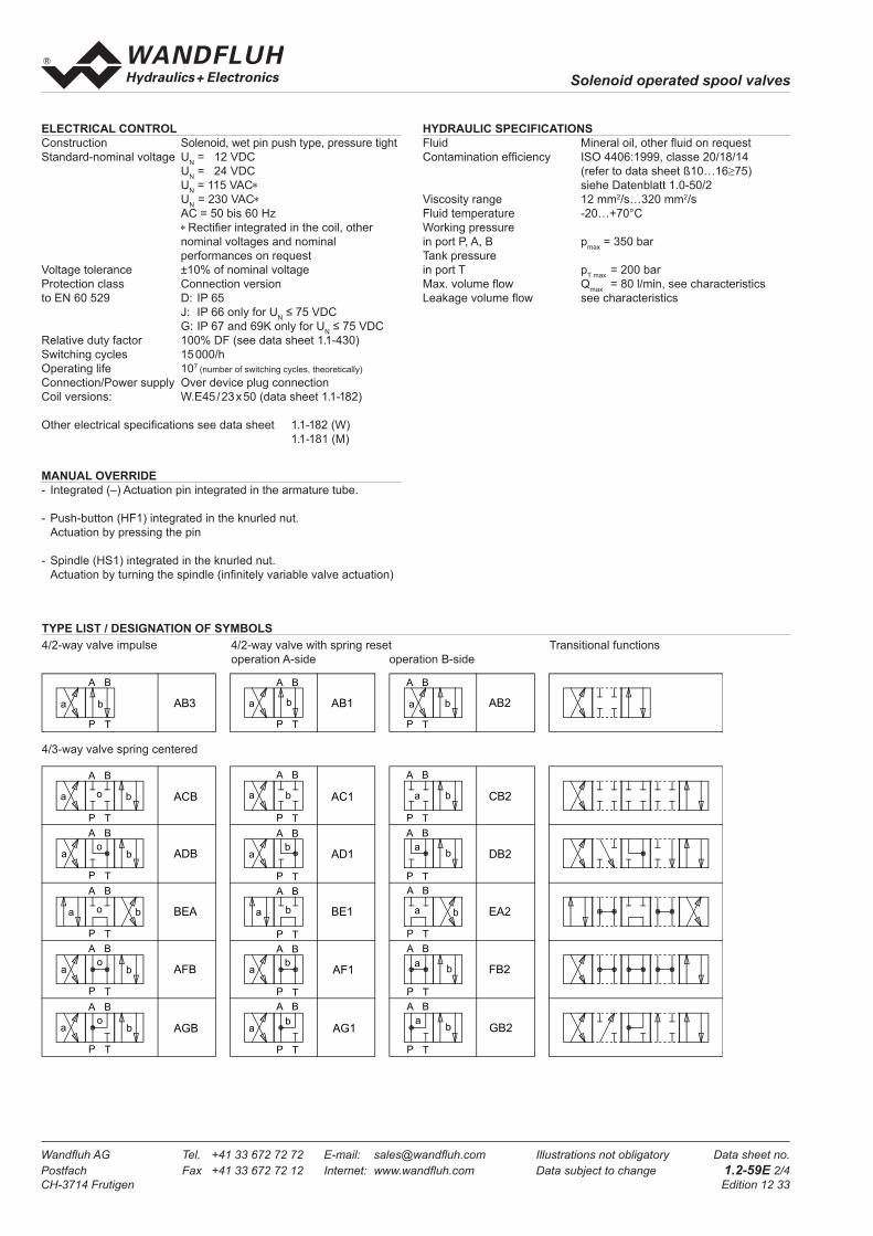
TYPE LIST / DESIGNATION OF SYMBOLS
4/3-way valve spring centered
4/2-way valve impulse 4/2-way valve with spring reset Transitional functions
operation A-side operation B-side
HYDRAULIC SPECIFICATIONS
Fluid Mineral oil, other fl uid on request
Contamination effi ciency ISO 4406:1999, classe 20/18/14
(refer to data sheet ß10…16≥75)
siehe Datenblatt 1.0-50/2
Viscosity range 12 mm2/s…320 mm2/s
Fluid temperature -20…+70°C
Working pressure
in port P, A, B pmax
= 350 bar
Tank pressure
in port T pT max
= 200 bar
Max. volume fl ow Qmax
= 80 l/min, see characteristics
Leakage volume fl ow see characteristics
a b
BA
P T
a b
BA
P T
o
a b
BA
P T
o
a b
BA
P T
o
a b
BA
P T
o
a b
BA
P T
a b
BA
P T
ab
BA
P T
a b
BA
P T
ab
BA
P T
ab
BA
P T
a b
BA
P T
a b
BA
P T
ab
BA
P T
a b
BA
P T
ab
BA
P T
ab
BA
P T
AB3
ACB
ADB
BEA
AFB
AGB
AB1
AC1
AD1
BE1
AF1
AG1
AB2
CB2
DB2
EA2
FB2
GB2
a b
BA
P T
o
Solenoid operated spool valves
Wandfl uh AG Tel. +41 33 672 72 72 E-mail: sales@wandfl uh.com Illustrations not obligatory Data sheet no.
Postfach Fax +41 33 672 72 12 Internet: www.wandfl uh.com Data subject to change 1.2-59E 3/4
CH-3714 Frutigen Edition 12 33
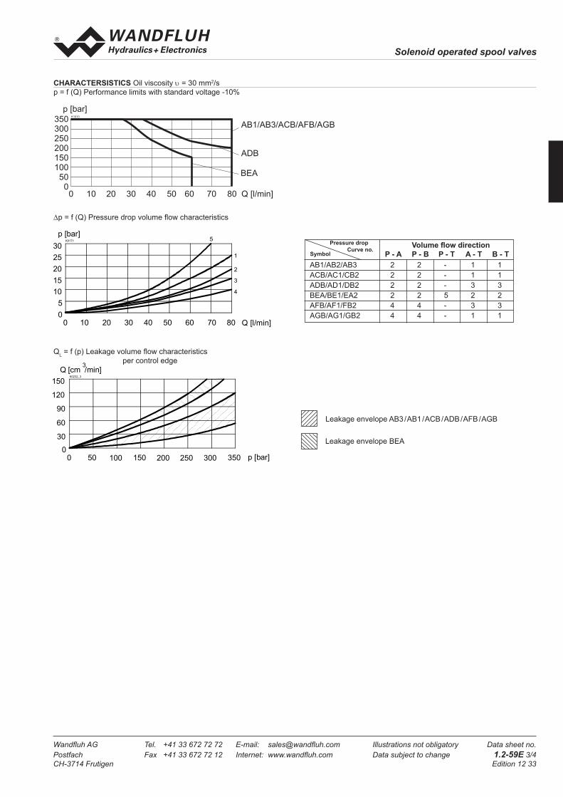
CHARACTERSISTICS Oil viscosity υ = 30 mm2/s
p = f (Q) Performance limits with standard voltage -10%
∆p = f (Q) Pressure drop volume fl ow characteristics
Volume fl ow direction
P - A P - B P - T A - T B - T
AB1/AB2/AB3 2 2 - 1 1
ACB/AC1/CB2 2 2 - 1 1
ADB/AD1/DB2 2 2 - 3 3
BEA/BE1/EA2 2 2 5 2 2
AFB/AF1/FB2 4 4 - 3 3
AGB/AG1/GB2 4 4 - 1 1
Pressure drop
Curve no.Symbol
QL = f (p) Leakage volume fl ow characteristics
per control edge
Leakage envelope AB3 / AB1 / ACB / ADB / AFB / AGB
Leakage envelope BEA
350300250200150100500
0 10 20 30 40 50 60 70 80 Q [l/min]
K1010
AB1/AB3/ACB/AFB/AGB
ADB
BEA
p [bar]
0800
K0171
10 30 50 70 Q [l/min]20 40 60
p [bar]
5
10
15
20
25
305
1
2
3
4
p [bar]
K0232_3
Q [cm /min]3
0 50 100 150 200 250 300 3500
30
60
90
120
150

Solenoid operated spool valves
Wandfl uh AG Tel. +41 33 672 72 72 E-mail: sales@wandfl uh.com Illustrations not obligatory Data sheet no.
Postfach Fax +41 33 672 72 12 Internet: www.wandfl uh.com Data subject to change 1.2-59E 4/4
CH-3714 Frutigen Edition 12 33
DIMENSIONS
4/3-way valve (spring centred)
4/2-way valve (impulse)
4/2-way valve (spring reset)
PARTS LIST
ACCESSORIES
Threaded connecting plates, Multi-fl ange subplates
and Longitudinal stacking system see Reg. 2.9
Mating connector (A) EN175301-803 article no. 219.2001
Mating connector (B) EN 175301-803 article no. 219.2002
Technical explanation see data sheet 1.0-100
46
17.8
21
32.5
31
40.5
21.5
B
T
P
A
BA
207.4
A
5.5
(8)
41
85.7
(19.7) 50 68
49
12.6
150.3
Ø45
Ø 9.5
37.2
57.2
37.2
50.7
Push-button
Spindle
80
50
70
6010
90
Position Article Description
10 206.1... W.E45/23x50
50 160.2093
160.6092
O-ring ID 9,25x1,78 (NBR)
O-ring ID 9,25x1,78 (FKM)
60 160.2222
160.6222
O-ring ID 22,22x2,62 (NBR)
O-ring ID 22,22x2,62 (FKM)
70 154.2701 Knurled nut
80 253.7004 Push-button
90 253.7002 Spindle
Solenoid operated spool valves
Wandfl uh AG Tel. +41 33 672 72 72 E-mail: sales@wandfl uh.com Illustrations not obligatory Data sheet no.
Postfach Fax +41 33 672 72 12 Internet: www.wandfl uh.com Data subject to change 1.2-60E 1/4
CH-3714 Frutigen Edition 13 50
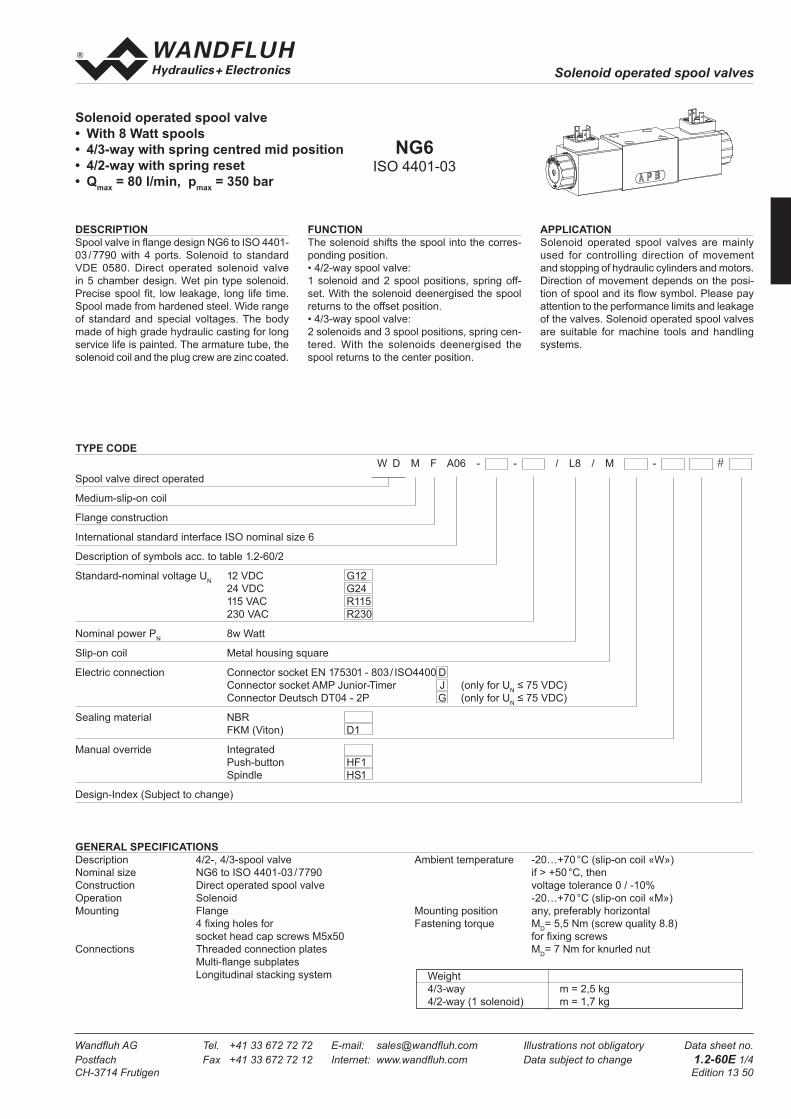
Solenoid operated spool valve
• With 8 Watt spools
• 4/3-way with spring centred mid position
• 4/2-way with spring reset
• Qmax
= 80 l/min, pmax
= 350 bar
GENERAL SPECIFICATIONS
Description 4/2-, 4/3-spool valve Ambient temperature -20…+70 °C (slip-on coil «W»)
Nominal size NG6 to ISO 4401-03 / 7790 if > +50 °C, then
Construction Direct operated spool valve voltage tolerance 0 / -10%
Operation Solenoid -20…+70 °C (slip-on coil «M»)
Mounting Flange Mounting position any, preferably horizontal
4 fi xing holes for Fastening torque MD= 5,5 Nm (screw quality 8.8)
socket head cap screws M5x50 for fi xing screws
Connections Threaded connection plates MD= 7 Nm for knurled nut
Multi-fl ange subplates
Longitudinal stacking system
APPLICATION
Solenoid operated spool valves are mainly
used for controlling direction of movement
and stopping of hydraulic cylinders and motors.
Direction of movement depends on the posi-
tion of spool and its fl ow symbol. Please pay
attention to the performance limits and leakage
of the valves. Solenoid operated spool valves
are suitable for machine tools and handling
systems.
DESCRIPTION
Spool valve in fl ange design NG6 to ISO 4401-
03 / 7790 with 4 ports. Solenoid to standard
VDE 0580. Direct operated solenoid valve
in 5 chamber design. Wet pin type solenoid.
Precise spool fi t, low leakage, long life time.
Spool made from hardened steel. Wide range
of standard and special voltages. The body
made of high grade hydraulic casting for long
service life is painted. The armature tube, the
solenoid coil and the plug crew are zinc coated.
FUNCTION
The solenoid shifts the spool into the corres-
ponding position.
• 4/2-way spool valve:
1 solenoid and 2 spool positions, spring off-
set. With the solenoid deenergised the spool
returns to the offset position.
• 4/3-way spool valve:
2 solenoids and 3 spool positions, spring cen-
tered. With the solenoids deenergised the
spool returns to the center position.
NG6ISO 4401-03
Weight
4/3-way m = 2,5 kg
4/2-way (1 solenoid) m = 1,7 kg
TYPE CODE
W D M F A06 - - / L8 / M - #
Spool valve direct operated
Medium-slip-on coil
Flange construction
International standard interface ISO nominal size 6
Description of symbols acc. to table 1.2-60/2
Standard-nominal voltage UN 12 VDC G12
24 VDC G24
115 VAC R115
230 VAC R230
Nominal power PN 8w Watt
Slip-on coil Metal housing square
Electric connection Connector socket EN 175301 - 803 / ISO4400 D
Connector socket AMP Junior-Timer J (only for UN ≤ 75 VDC)
Connector Deutsch DT04 - 2P G (only for UN ≤ 75 VDC)
Sealing material NBR
FKM (Viton) D1
Manual override Integrated
Push-button HF1
Spindle HS1
Design-Index (Subject to change)
Solenoid operated spool valves
Wandfl uh AG Tel. +41 33 672 72 72 E-mail: sales@wandfl uh.com Illustrations not obligatory Data sheet no.
Postfach Fax +41 33 672 72 12 Internet: www.wandfl uh.com Data subject to change 1.2-60E 2/4
CH-3714 Frutigen Edition 13 50
ELECTRICAL CONTROL
Construction Solenoid, wet pin push type, pressure tight
Standard-nominal voltage UN = 12 VDC
UN = 24 VDC
UN = 115 VAC∗
UN
= 230 VAC∗
AC = 50 bis 60 Hz
∗ Rectifi er integrated in the coil, other
nominal voltages and nominal
performances on request
Voltage tolerance ±10% of nominal voltage
Protection class Connection version
to EN 60 529 D: IP 65
J: IP 66 only for UN ≤ 75 VDC
G: IP 67 and 69K only for UN ≤ 75 VDC
Relative duty factor 100% DF (see data sheet 1.1-430)
Switching cycles 15 000/h
Operating life 107 (number of switching cycles, theoretically)
Connection/Power supply Over device plug connection
Other electrical specifi cations see data sheet 1.1-181
MANUAL OVERRIDE
- Integrated (–) Actuation pin integrated in the armature tube.
- Push-button (HF1) integrated in the knurled nut.
Actuation by pressing the pin
- Spindle (HS1) integrated in the knurled nut.
Actuation by turning the spindle (infi nitely variable valve actuation)
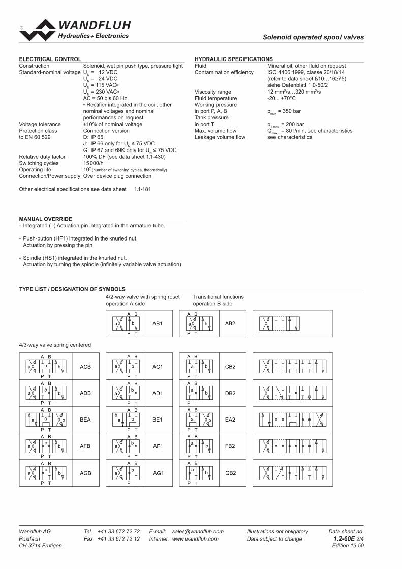
TYPE LIST / DESIGNATION OF SYMBOLS
4/3-way valve spring centered
4/2-way valve with spring reset Transitional functions
operation A-side operation B-side
HYDRAULIC SPECIFICATIONS
Fluid Mineral oil, other fl uid on request
Contamination effi ciency ISO 4406:1999, classe 20/18/14
(refer to data sheet ß10…16≥75)
siehe Datenblatt 1.0-50/2
Viscosity range 12 mm2/s…320 mm2/s
Fluid temperature -20…+70°C
Working pressure
in port P, A, B pmax
= 350 bar
Tank pressure
in port T pT max
= 200 bar
Max. volume fl ow Qmax
= 80 l/min, see characteristics
Leakage volume fl ow see characteristics
a b
BA
P T
a b
BA
P T
AB1 AB2
a b
BA
P T
a b
BA
P T
o
a b
BA
P T
o
a b
BA
P T
o
a b
BA
P T
o
a b
BA
P T
ab
BA
P T
a b
BA
P T
ab
BA
P T
ab
BA
P T
a b
BA
P T
ab
BA
P T
a b
BA
P T
ab
BA
P T
ab
BA
P T
ACB
ADB
BEA
AFB
AGB
AC1
AD1
BE1
AF1
AG1
CB2
DB2
EA2
FB2
GB2
o

Solenoid operated spool valves
Wandfl uh AG Tel. +41 33 672 72 72 E-mail: sales@wandfl uh.com Illustrations not obligatory Data sheet no.
Postfach Fax +41 33 672 72 12 Internet: www.wandfl uh.com Data subject to change 1.2-60E 3/4
CH-3714 Frutigen Edition 13 50
CHARACTERSISTICS Oil viscosity υ = 30 mm2/s
p = f (Q) Performance limits with standard voltage -10%
∆p = f (Q) Pressure drop volume fl ow characteristics
Volume fl ow direction
P - A P - B P - T A - T B - T
AB1/AB2 2 2 - 1 1
ACB/AC1/CB2 2 2 - 1 1
ADB/AD1/DB2 2 2 - 3 3
BEA/BE1/EA2 2 2 5 2 2
AFB/AF1/FB2 4 4 - 3 3
AGB/AG1/GB2 4 4 - 1 1
Pressure drop
Curve no.Symbol
QL = f (p) Leakage volume fl ow characteristics
per control edge
Leakage envelope AB1 / ACB / ADB / AFB / AGB
Leakage envelope BEA
0800
K0171
10 30 50 70 Q [l/min]20 40 60
p [bar]
5
10
15
20
25
305
1
2
3
4
p [bar]
K0232_3
Q [cm /min]3
0 50 100 150 200 250 300 3500
30
60
90
120
150
350300250200150100
500
0 10 20 30 40 50 60 70 80 Q [l/min]
K1086
ACB
AB1
ADBBEA
AFB
AGB
p [bar]

Solenoid operated spool valves
Wandfl uh AG Tel. +41 33 672 72 72 E-mail: sales@wandfl uh.com Illustrations not obligatory Data sheet no.
Postfach Fax +41 33 672 72 12 Internet: www.wandfl uh.com Data subject to change 1.2-60E 4/4
CH-3714 Frutigen Edition 13 50
DIMENSIONS
4/3-way valve (spring centred) 4/2-way valve (spring reset)
PARTS LIST
ACCESSORIES
Threaded connecting plates, Multi-fl ange subplates
and Longitudinal stacking system see Reg. 2.9
Mating connector (A) EN175301-803 article no. 219.2001
Mating connector (B) EN 175301-803 article no. 219.2002
Technical explanation see data sheet 1.0-100
Position Article Description
10 206.1... M.S45/23x50
50 160.2093
160.6092
O-ring ID 9,25x1,78 (NBR)
O-ring ID 9,25x1,78 (FKM)
60 160.2222
160.6222
O-ring ID 22,22x2,62 (NBR)
O-ring ID 22,22x2,62 (FKM)
70 154.2701 Knurled nut
80 253.7004 Push-button
90 253.7002 Spindle
A B
207.410
46
17.8
21
32.5
31
40.5
21.5
B
T
P
A
A
85.8
Ø 5.5
Ø 9.5
41
8
45
68 12.6
150.3
49
5316.7
37.2
50.7
37.2
57.2
Push-button
Spindle
70
60
90
80
50

Solenoid operated spool valves
Wandfl uh AG Tel. +41 33 672 72 72 E-mail: sales@wandfl uh.com Illustrations not obligatory Data sheet no.
Postfach Fax +41 33 672 72 12 Internet: www.wandfl uh.com Data subject to change 1.2-75E 1/4
CH-3714 Frutigen Edition 13 36
Solenoid operated spool valve
• 4/2-way impulse valve
• 4/3-way with spring centred mid position
• 4/2-way with spring reset
• Qmax
= 160 l/min, pmax
= 350 bar
GENERAL SPECIFICATIONS
Description 4/2-, 4/3-spool valve Ambient temperature -20…+70 °C
Nominal size NG10 to ISO 4401-05 / 7790 if > +50 °C, then
Construction Direct operated spool valve voltage tolerance 0 / -10%
Operation Solenoid Mounting position any, preferably horizontal
Mounting Flange Fastening torque MD= 9,5 Nm (screw quality 8.8)
4 fi xing holes for for fi xing screws
socket head cap screws M6x70 MD= 7 Nm for knurled nut
Connections Threaded connection plates
Multi-fl ange subplates
Longitudinal stacking system
APPLICATION
Solenoid operated spool valves are mainly
used for controlling direction of movement
and stopping of hydraulic cylinders and motors.
Direction of movement depends on the posi-
tion of spool and its fl ow symbol. Please pay
attention to the performance limits and leakage
of the valves. Solenoid operated spool valves
are suitable for machine tools and handling
systems.
DESCRIPTION
Spool valve in fl ange design NG10 to ISO 4401-
05 / 7790 with 4 ports. Solenoid to standard
VDE 0580. Direct operated solenoid valve in 5
chamber design. Spool deteted or with spring
reset. Wet pin type solenoid. Precise spool
fi t, low leakage, long life time. Spool made
from hardened steel. Wide range of standard
and special voltages. The body made of high
grade hydraulic casting for long service life is
painted. The armature tube and the plug crew
are zinc coated. The solenoid coil is nickel-/
chromium-coated.
FUNCTION
The solenoid shifts the spool into the corres-
ponding position.
• 4/2-way detented spool valve:
2 solenoids and 2 detented positions. With the
solenoids deenergised the spool remains in the
last switched position.
• 4/2-way spool valve:
1 solenoid and 2 spool positions, spring off-
set. With the solenoid deenergised the spool
returns to the offset position.
• 4/3-way spool valve:
2 solenoids and 3 spool positions, spring cen-
tered. With the solenoids deenergised the
spool returns to the center position.
NG10ISO 4401-05
W D M F A10 - - / W - #
Spool valve direct operated
Medium-slip-on coil
Flange construction
International standard interface ISO nominal size 10
Description of symbols acc. to table 1.2-75/2
Standard-nominal voltage UN 12 VDC G12
24 VDC G24
without solenoid coil X5
Slip-on coil Metal housing round W
Electric connection Connector socket EN 175301 - 803 / ISO4400 D
Connector socket AMP Junior-Timer J (only for UN ≤ 75 VDC)
Connector Deutsch DT04 - 2P G (only for UN ≤ 75 VDC)
Sealing material NBR
FKM (Viton) D1
Manual override Integrated
Push-button HF1
Spindle HS1
Design-Index (Subject to change)
TYPE CODE
Weight
4/2-way impulse m = 5,9 kg
4/3-way m = 5,9 kg
4/2-way (1 solenoid) m = 4,4 kg
Solenoid operated spool valves
Wandfl uh AG Tel. +41 33 672 72 72 E-mail: sales@wandfl uh.com Illustrations not obligatory Data sheet no.
Postfach Fax +41 33 672 72 12 Internet: www.wandfl uh.com Data subject to change 1.2-75E 2/4
CH-3714 Frutigen Edition 13 36
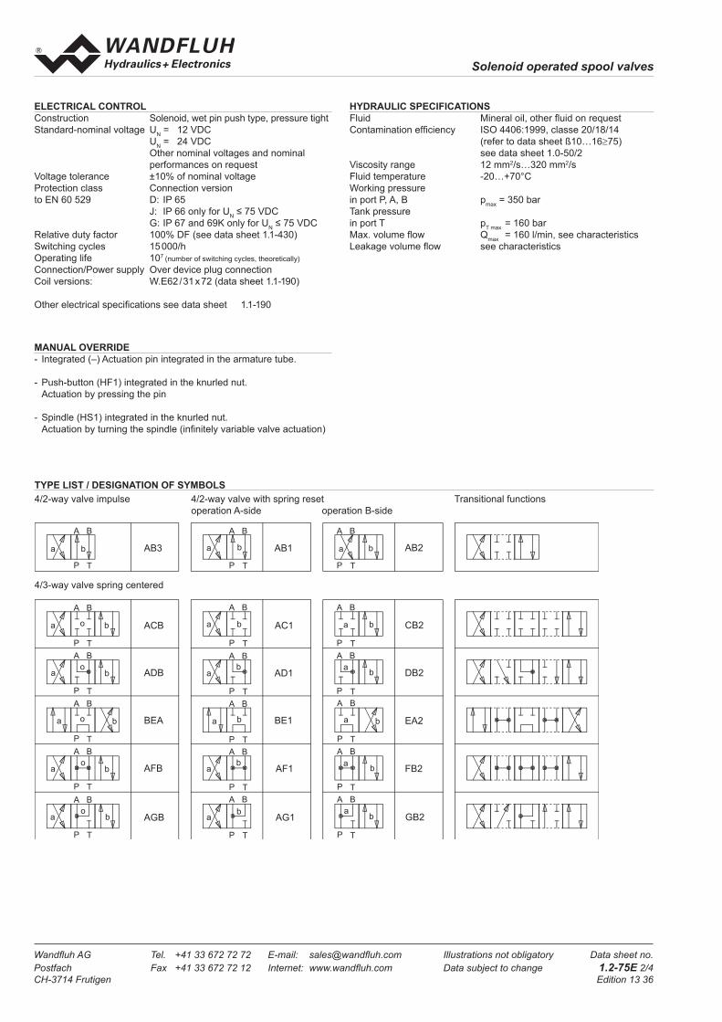
ELECTRICAL CONTROL
Construction Solenoid, wet pin push type, pressure tight
Standard-nominal voltage UN = 12 VDC
UN = 24 VDC
Other nominal voltages and nominal
performances on request
Voltage tolerance ±10% of nominal voltage
Protection class Connection version
to EN 60 529 D: IP 65
J: IP 66 only for UN ≤ 75 VDC
G: IP 67 and 69K only for UN ≤ 75 VDC
Relative duty factor 100% DF (see data sheet 1.1-430)
Switching cycles 15 000/h
Operating life 107 (number of switching cycles, theoretically)
Connection/Power supply Over device plug connection
Coil versions: W.E62 / 31 x 72 (data sheet 1.1-190)
Other electrical specifi cations see data sheet 1.1-190
MANUAL OVERRIDE
- Integrated (–) Actuation pin integrated in the armature tube.
- Push-button (HF1) integrated in the knurled nut.
Actuation by pressing the pin
- Spindle (HS1) integrated in the knurled nut.
Actuation by turning the spindle (infi nitely variable valve actuation)
TYPE LIST / DESIGNATION OF SYMBOLS
4/3-way valve spring centered
4/2-way valve impulse 4/2-way valve with spring reset Transitional functions
operation A-side operation B-side
a b
BA
P T
a b
BA
P T
o
a b
BA
P T
o
a b
BA
P T
o
a b
BA
P T
o
a b
BA
P T
a b
BA
P T
ab
BA
P T
a b
BA
P T
ab
BA
P T
ab
BA
P T
a b
BA
P T
a b
BA
P T
ab
BA
P T
a b
BA
P T
ab
BA
P T
ab
BA
P T
AB3
ACB
ADB
BEA
AFB
AGB
AB1
AC1
AD1
BE1
AF1
AG1
AB2
CB2
DB2
EA2
FB2
GB2
a b
BA
P T
o
HYDRAULIC SPECIFICATIONS
Fluid Mineral oil, other fl uid on request
Contamination effi ciency ISO 4406:1999, classe 20/18/14
(refer to data sheet ß10…16≥75)
see data sheet 1.0-50/2
Viscosity range 12 mm2/s…320 mm2/s
Fluid temperature -20…+70°C
Working pressure
in port P, A, B pmax
= 350 bar
Tank pressure
in port T pT max
= 160 bar
Max. volume fl ow Qmax
= 160 l/min, see characteristics
Leakage volume fl ow see characteristics

Solenoid operated spool valves
Wandfl uh AG Tel. +41 33 672 72 72 E-mail: sales@wandfl uh.com Illustrations not obligatory Data sheet no.
Postfach Fax +41 33 672 72 12 Internet: www.wandfl uh.com Data subject to change 1.2-75E 3/4
CH-3714 Frutigen Edition 13 36
CHARACTERSISTICS Oil viscosity υ = 30 mm2/s
p = f (Q) Performance limits with standard voltage -10%
∆p = f (Q) Pressure drop volume fl ow characteristics
Volume fl ow direction
P - A P - B P - T A - T B - T
AB1 2 2 – 4 4
AB3 2 2 – 4 4
ACB 2 2 – 2 2
ADB 1 1 – 5 5
BEA 3 3 6 4 4
AFB 4 4 5 5 5
AGB 4 4 – 2 2
Pressure drop
Curve no.Symbol
QL = f (p) Leakage volume fl ow characteristics per control edge
Leakage envelope AB3 / AB1 / ACB / ADB / AFB / AGB
Leakage envelope BEA
350300250200150100500
0 20 40 60 80 100 120 140 160 Q [l/min]
K1021
AGB / AB3 / AFB
AB1
BEA
p [bar] ADB / ACB
0 20 40 60 80 100 120 140 160 Q [l/min]
20
15
10
5
0
K1022
p [bar]6 1
2
3
4
5
0 50 100 150 200 250 300 350 p [bar]
Q [cm3/min]300
250
200
150
100
50
0
K1023

Solenoid operated spool valves
Wandfl uh AG Tel. +41 33 672 72 72 E-mail: sales@wandfl uh.com Illustrations not obligatory Data sheet no.
Postfach Fax +41 33 672 72 12 Internet: www.wandfl uh.com Data subject to change 1.2-75E 4/4
CH-3714 Frutigen Edition 13 36
DIMENSIONS
4/3-way valve (spring centred)
4/2-way valve (impulse)
4/2-way valve (spring reset)
PARTS LIST
ACCESSORIES
Threaded connecting plates, Multi-fl ange subplates
and Longitudinal stacking system see Reg. 2.9
Mating connector (A) EN175301-803 article no. 219.2001
Mating connector (B) EN 175301-803 article no. 219.2002
Technical explanation see data sheet 1.0-100
BA
307
10
A
54
1.5
20.8
16.8
9.7
46 68
48
T
A B
T0
P
106.
5
6011Ø 6.5
Ø 10.5
14.2
71
937235
Ø62
214.2
51.4
64.9
51.4
71.4
50
70
60
80
90
Push-button
Spindle
Position Article Description
10 206.3... W.E62/31x72
50 160.2120
160 8124
O-ring ID 12,42x1,78 (NBR)
O-ring ID 12,42x1,78 (FKM)
60 160.2282
160.6282
O-ring ID 28,24x2,62 (NBR)
O-ring ID 28,24x2,62 (FKM)
70 154.2706 Knurled nut
80 253.7006 Push-button
90 253.7005 Spindle

Wandfl uh AG Tel. +41 33 672 72 72 E-mail: sales@wandfl uh.com llustrations not obligatory Data sheet no.
Postfach Fax +41 33 672 72 12 Internet: www.wandfl uh.com Data subject to change 1.4-13E 1/4
CH-3714 Frutigen Edition 13 09
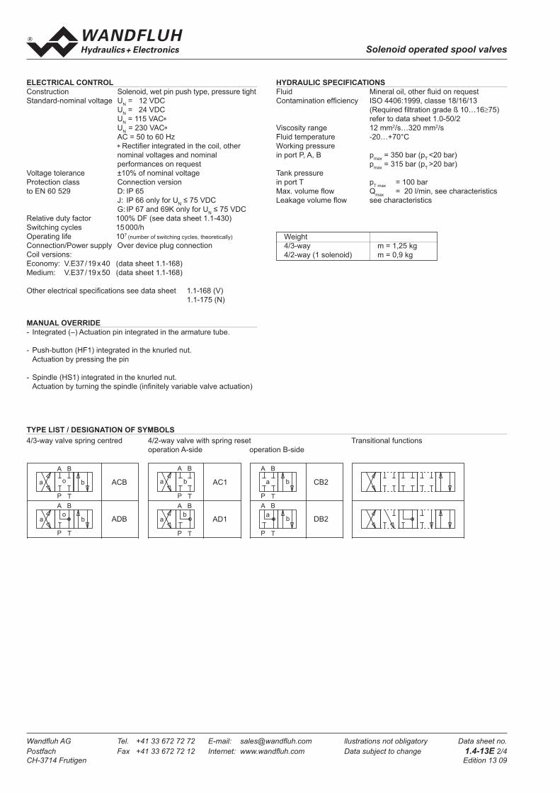
Solenoid operated spool valves
Solenoid operated spool valve soft switching
• 4/3-way with spring centred mid position
• 4/2-way with spring reset
• Qmax
= 20 l/min, pmax
= 350 bar
FUNCTION
The solenoid shifts the spool into the corres-
ponding position.
• 4/3-way spool valve:
2 solenoids and 3 spool positions, spring cen-
tered. With the solenoids deenergised the
spool returns to the center position.
• 4/2-way spool valve:
1 solenoid and 2 spool positions, spring off-
set. With the solenoid deenergised the spool
returns to the offset position.
APPLICATION
Normal solenoid spool valves switch very
quickly. This can induce shocks in the hydraulic
system which can cause mechanical wear and
have a negative effect on performance. The
soft switching valves slow down and dampen
the switching movements. All starting, stopping
and oscillating movements are done softly,
which benefi ts the system. Optimum results
can be achieved if all ports are connected and
the valve is properly bleed of air. Individual
settings are available on request.
Important: at the time the valve is taken into
service, the valve must be vented under pres-
sure (max. 2 revolutions of screw E).
DESCRIPTION
Spool valve with soft switching, NG4-Mini
fl ange construction in accordance to Wand-
fl uh-standard with 4 connections. Solenoids
to norme VDE 0580. Direct solenoid operated
spool valve with a 5 annular chamber body
design. The valve’s with soft switching charac-
teristic is achieved by means of an optimum
combination of removable oriffi ce and pistion
design. Solenoid wet pin oil immersed armature
type. Precision honed spool for low leakage.
Low pressure drop due to the body design
and spool profi ling. Spool is of hardened steel,
body is of high grade hydraulic cast iron for
long service life. Wide range of standard and
special voltages. The body made of high grade
hydraulic casting for long service life is painted.
The armature tube and the plug crew are zinc
coated. The solenoid coil is nickel-/chromium-
coated.
NG4-Mini®
GENERAL SPECIFICATIONS
Description 4/2-, 4/3-spool valve
Nominal size NG4-Mini to Wandfl uh standard
Construction Direct operated spool valve
Operation Solenoid
Mounting Flange
3 fi xing holes for
socket head cap screws M5x40
Connections Threaded connection plates
Multi-fl ange subplates
Longitudinal stacking system
Ambient temperature -20…+70 °C (slip-on coil«V»)
if > +50 °C, then
voltage tolerance 0 / -10%
-20…+70 °C (slip-on coil «N»)
Mounting position any, preferably horizontal
Fastening torque MD= 5,5 Nm (screw quality 8.8)
For fi xing screws
MD= 5 Nm for Knurled nut
W W M F A04 - - / - # Spool valve soft switching
Medium-slip-on coil
Flange construction
Mounting interface acc. to Wandfl uh standard, NG4-Mini
Description of symbols acc. to table 1.4-13/2
Standard-nominal voltage UN 12 VDC G12
24 VDC G24
115 VAC R115
230 VAC R230
without solenoid coil X5
Slip-on coil Metal housing round with one-sided collar V
Metal housing square with one-sided collar N*
Electric connection Connector socket EN 175301 - 803 / ISO4400 D
Connector socket AMP Junior-Timer J (only for UN ≤ 75 VDC)
Connector Deutsch DT04 - 2P G (only for UN ≤ 75 VDC)
Sealing material NBR
FKM (Viton) D1
Manual override Integrated
Push-button HF1
Spindle HS1
Diameter of orifi ce ø 0,3 mm (Standard)
Design-Index (Subject to change)
* Only available in conjunction with other nominal voltages and connection versions. (See data sheet 1.1-175)
TYPE CODE
Wandfl uh AG Tel. +41 33 672 72 72 E-mail: sales@wandfl uh.com llustrations not obligatory Data sheet no.
Postfach Fax +41 33 672 72 12 Internet: www.wandfl uh.com Data subject to change 1.4-13E 2/4
CH-3714 Frutigen Edition 13 09
Solenoid operated spool valves
Weight
4/3-way m = 1,25 kg
4/2-way (1 solenoid) m = 0,9 kg
a b
BA
P T
a b
BA
P T
o
a b
BA
P T
o
a b
BA
P T
o
a b
BA
P T
o
a b
BA
P T
a b
BA
P T
ab
BA
P T
a b
BA
P T
ab
BA
P T
ab
BA
P T
a b
BA
P T
a b
BA
P T
ab
BA
P T
a b
BA
P T
ab
BA
P T
ab
BA
P T
A B 3
A C B
A D B
B E A
A F B
A G B
A B 1
A C 1
A D 1
B E 1
A F 1
A G 1
A B 2
C B 2
D B 2
E A 2
F B 2
G B 2
a b
BA
P T
o
TYPE LIST / DESIGNATION OF SYMBOLS
4/3-way valve spring centred 4/2-way valve with spring reset Transitional functions
operation A-side operation B-side
MANUAL OVERRIDE
- Integrated (–) Actuation pin integrated in the armature tube.
- Push-button (HF1) integrated in the knurled nut.
Actuation by pressing the pin
- Spindle (HS1) integrated in the knurled nut.
Actuation by turning the spindle (infi nitely variable valve actuation)
HYDRAULIC SPECIFICATIONS
Fluid Mineral oil, other fl uid on request
Contamination effi ciency ISO 4406:1999, classe 18/16/13
(Required fi ltration grade ß 10…16≥75)
refer to data sheet 1.0-50/2
Viscosity range 12 mm2/s…320 mm2/s
Fluid temperature -20…+70°C
Working pressure
in port P, A, B pmax
= 350 bar (pT <20 bar)
pmax
= 315 bar (pT >20 bar)
Tank pressure
in port T pT max
= 100 bar
Max. volume fl ow Qmax
= 20 l/min, see characteristics
Leakage volume fl ow see characteristics
ELECTRICAL CONTROL
Construction Solenoid, wet pin push type, pressure tight
Standard-nominal voltage UN = 12 VDC
UN = 24 VDC
UN = 115 VAC∗
UN
= 230 VAC∗
AC = 50 to 60 Hz
∗ Rectifi er integrated in the coil, other
nominal voltages and nominal
performances on request
Voltage tolerance ±10% of nominal voltage
Protection class Connection version
to EN 60 529 D: IP 65
J: IP 66 only for UN ≤ 75 VDC
G: IP 67 and 69K only for UN ≤ 75 VDC
Relative duty factor 100% DF (see data sheet 1.1-430)
Switching cycles 15 000/h
Operating life 107 (number of switching cycles, theoretically)
Connection/Power supply Over device plug connection
Coil versions:
Economy: V.E37 / 19 x 40 (data sheet 1.1-168)
Medium: V.E37 / 19 x 50 (data sheet 1.1-168)
Other electrical specifi cations see data sheet 1.1-168 (V)
1.1-175 (N)

Wandfl uh AG Tel. +41 33 672 72 72 E-mail: sales@wandfl uh.com llustrations not obligatory Data sheet no.
Postfach Fax +41 33 672 72 12 Internet: www.wandfl uh.com Data subject to change 1.4-13E 3/4
CH-3714 Frutigen Edition 13 09
Solenoid operated spool valves
Volume fl ow direction
P - A P - B P - T A - T B - T
ACB 3 3 - 3 3
ADB 2 2 - 1 1
Pressure drop
Curve no.Symbol
∆p = f (Q) Pressure drop volume fl ow characteristics
CHARACTERSISTICS Oilviscosity υ = 30 mm2/s
p = f (Q) Performance limits with standard voltage -10%
SWITCHING TIMES Infl uence of soft switching
Measured with WWMFA04-ACB-G24 at Q = 10 l/min compared with WDMFA04-ACB-G24
Solenoid energised Orifi ces in valve body infl uence shifting time
Solenoid deenergised
(Pressure mesured in P)
(Pressure mesured in P)
K1035
p [bar]
350300250200150100500
0 5 10 15 20
ACB
ADB
K1036
p [bar]
3
2
1
0 5 10 15 20
4035302520151050
QL = f (p) Leakage volume fl ow characteristics per control edge
K1037
Q [cm3/min]
60
50
40
30
20
10
00 50 100 150 200
Standard valve
Soft-switching valve
K1049
Standard valve
Soft-switching valve
K1050
Wandfl uh AG Tel. +41 33 672 72 72 E-mail: sales@wandfl uh.com llustrations not obligatory Data sheet no.
Postfach Fax +41 33 672 72 12 Internet: www.wandfl uh.com Data subject to change 1.4-13E 4/4
CH-3714 Frutigen Edition 13 09
Solenoid operated spool valves
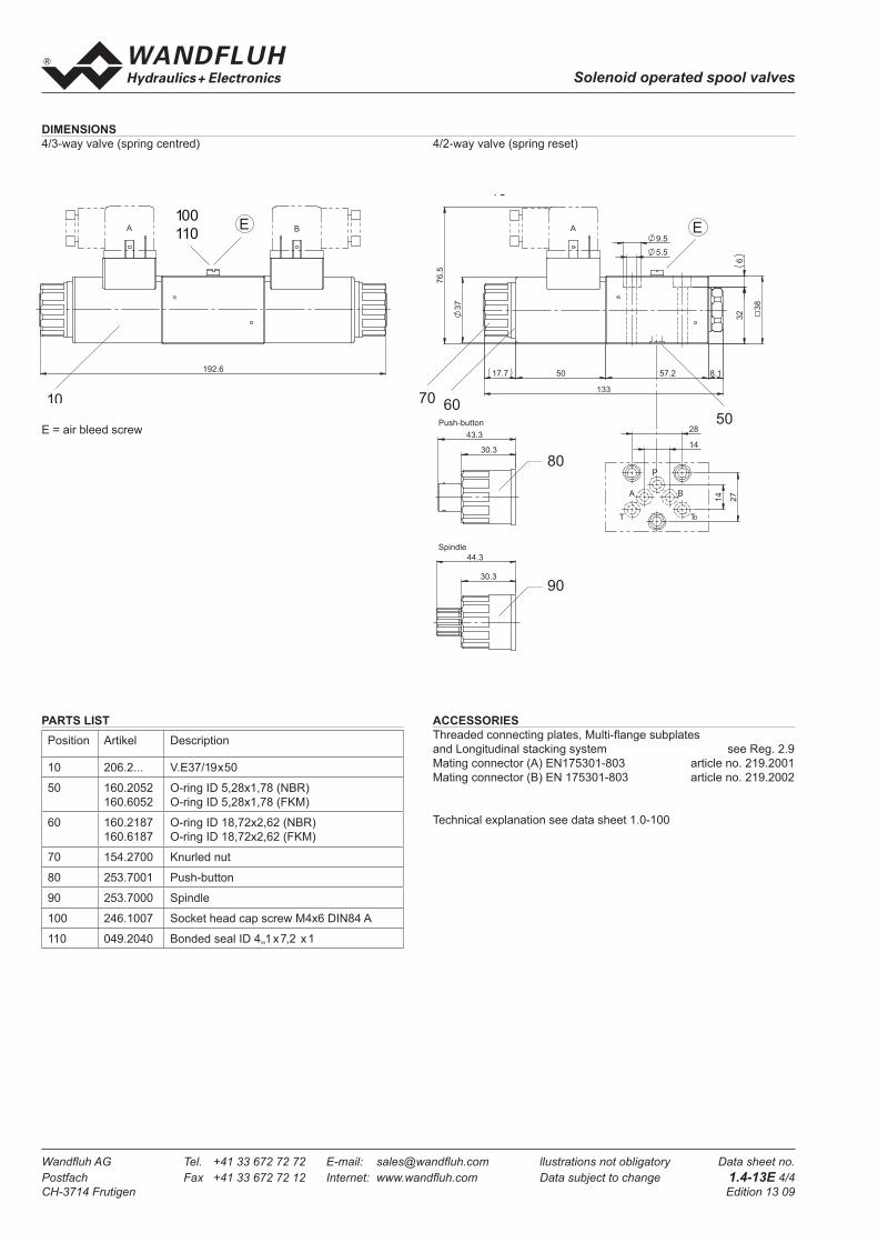
PARTS LIST
Position Artikel Description
10 206.2... V.E37/19x50
50 160.2052
160.6052
O-ring ID 5,28x1,78 (NBR)
O-ring ID 5,28x1,78 (FKM)
60 160.2187
160.6187
O-ring ID 18,72x2,62 (NBR)
O-ring ID 18,72x2,62 (FKM)
70 154.2700 Knurled nut
80 253.7001 Push-button
90 253.7000 Spindle
100 246.1007 Socket head cap screw M4x6 DIN84 A
110 049.2040 Bonded seal ID 4,,1 x 7,2 x 1
ACCESSORIES
Threaded connecting plates, Multi-fl ange subplates
and Longitudinal stacking system see Reg. 2.9
Mating connector (A) EN175301-803 article no. 219.2001
Mating connector (B) EN 175301-803 article no. 219.2002
Technical explanation see data sheet 1.0-100
E = air bleed screw
DIMENSIONS
4/3-way valve (spring centred) 4/2-way valve (spring reset)
A B
192.6
10
E100
110A
32
6
5.5
9.5
76
.5
30.3
44.3
30.3
43.3
133
8.1 57.2 50
3
7
17.7
3
8
T
A B
0T
P
28
14
14
27
90
80
506070
10
E
Push-button
Spindle

Wandfl uh AG Tel. +41 33 672 72 72 E-mail: sales@wandfl uh.com llustrations not obligatory Data sheet no.
Postfach Fax +41 33 672 72 12 Internet: www.wandfl uh.com Data subject to change 1.4-23E 1/4
CH-3714 Frutigen Edition 13 09
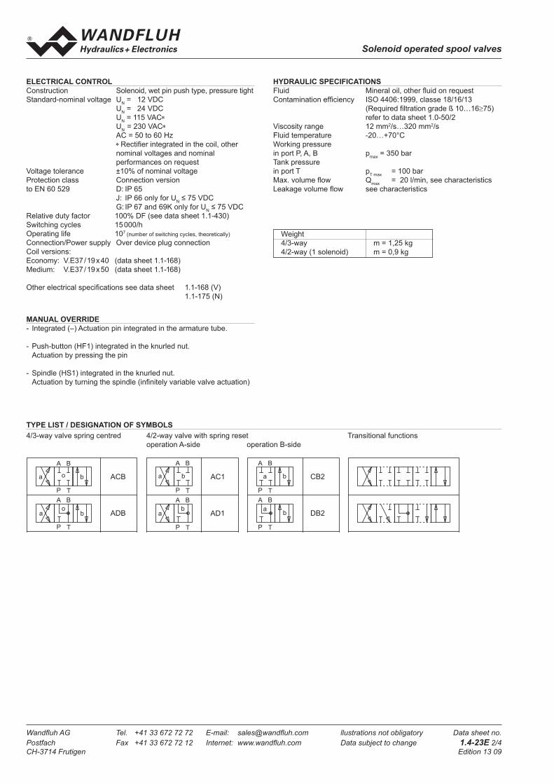
Solenoid operated spool valves
Solenoid operated spool valve with soft switching
• 4/3-way with spring centred mid position
• 4/2-way with spring reset
• Qmax
= 20 l/min, pmax
= 350 bar
FUNCTION
The solenoid shifts the spool into the corres-
ponding position.
• 4/3-way spool valve:
2 solenoids and 3 spool positions, spring cen-
tered. With the solenoids deenergised the
spool returns to the center position.
• 4/2-way spool valve:
1 solenoid and 2 spool positions, spring off-
set. With the solenoid deenergised the spool
returns to the offset position.
APPLICATION
Normal solenoid spool valves switch very
quickly. This can induce shocks in the hydraulic
system which can cause mechanical wear and
have a negative effect on performance. The
soft switching valves slow down and dampen
the switching movements. All starting, stopping
and oscillating movements are done softly,
which benefi ts the system. Optimum results
can be achieved if all ports are connected and
the valve is properly bleed of air. Individual
settings are available on request.
Important: at the time the valve is taken into
service, the valve must be vented under pres-
sure (max. 2 revolutions of screw E).
DESCRIPTION
Spool valve with soft switching, NG4 fl ange
construction in accordance to ISO 4401-02
with 4 connections. Solenoids to norme VDE
0580. Direct solenoid operated spool valve
with a 5 annular chamber body design. The
valve’s with soft switching charac-teristic is
achieved by means of an optimum combina-
tion of removable oriffi ce and pistion design.
Solenoid wet pin oil immersed armature type.
Precision honed spool for low leakage. Low
pressure drop due to the body design and spool
profi ling. Spool is of hardened steel, body is of
high grade hydraulic cast iron for long service
life. Wide range of standard voltages. The body
made of high grade hydraulic casting for long
service life is painted. The armature tube and
the plug crew are zinc coated. The solenoid
coil is nickel-/chromium-coated.
NG4®
ISO 4401-02
GENERAL SPECIFICATIONS
Description 4/2-, 4/3-spool valve
Nominal size NG4 to ISO 4401-02
Construction Direct operated spool valve
Operation Solenoid
Mounting Flange
4 fi xing holes for
socket head cap screws M5x40
Connections Threaded connection plates
Multi-fl ange subplates
Longitudinal stacking system
Ambient temperature -20…+70 °C (slip-on coil«V»)
if > +50 °C, then
voltage tolerance 0 / -10%
-20…+70 °C (slip-on coil «N»)
Mounting position any, preferably horizontal
Fastening torque MD= 5,5 Nm (screw quality 8.8)
For fi xing screws
MD= 5 Nm for Knurled nut
W W M F B04 - - / - # Spool valve soft switching
Medium-slip-on coil
Flange construction
International standard interface ISO, nominal size 4
Description of symbols acc. to table 1.4-23/2
Standard-nominal voltage UN 12 VDC G12
24 VDC G24
115 VAC R115
230 VAC R230
without solenoid coil X5
Slip-on coil Metal housing round with one-sided collar V
Metal housing square with one-sided collar N*
Electric connection Connector socket EN 175301 - 803 / ISO4400 D
Connector socket AMP Junior-Timer J (only for UN ≤ 75 VDC)
Connector Deutsch DT04 - 2P G (only for UN ≤ 75 VDC)
Sealing material NBR
FKM (Viton) D1
Manual override Integrated
Push-button HF1
Spindle HS1
Diameter of orifi ce ø 0,3 mm (Standard)
Design-Index (Subject to change)
* Only available in conjunction with other nominal voltages and connection versions. (See data sheet 1.1-175)
TYPE CODE
Wandfl uh AG Tel. +41 33 672 72 72 E-mail: sales@wandfl uh.com llustrations not obligatory Data sheet no.
Postfach Fax +41 33 672 72 12 Internet: www.wandfl uh.com Data subject to change 1.4-23E 2/4
CH-3714 Frutigen Edition 13 09
Solenoid operated spool valves
Weight
4/3-way m = 1,25 kg
4/2-way (1 solenoid) m = 0,9 kg
a b
BA
P T
a b
BA
P T
o
a b
BA
P T
o
a b
BA
P T
o
a b
BA
P T
o
a b
BA
P T
a b
BA
P T
ab
BA
P T
a b
BA
P T
ab
BA
P T
ab
BA
P T
a b
BA
P T
a b
BA
P T
ab
BA
P T
a b
BA
P T
ab
BA
P T
ab
BA
P T
A B 3
A C B
A D B
B E A
A F B
A G B
A B 1
A C 1
A D 1
B E 1
A F 1
A G 1
A B 2
C B 2
D B 2
E A 2
F B 2
G B 2
a b
BA
P T
o
TYPE LIST / DESIGNATION OF SYMBOLS
4/3-way valve spring centred 4/2-way valve with spring reset Transitional functions
operation A-side operation B-side
MANUAL OVERRIDE
- Integrated (–) Actuation pin integrated in the armature tube.
- Push-button (HF1) integrated in the knurled nut.
Actuation by pressing the pin
- Spindle (HS1) integrated in the knurled nut.
Actuation by turning the spindle (infi nitely variable valve actuation)
HYDRAULIC SPECIFICATIONS
Fluid Mineral oil, other fl uid on request
Contamination effi ciency ISO 4406:1999, classe 18/16/13
(Required fi ltration grade ß 10…16≥75)
refer to data sheet 1.0-50/2
Viscosity range 12 mm2/s…320 mm2/s
Fluid temperature -20…+70°C
Working pressure
in port P, A, B pmax
= 350 bar
Tank pressure
in port T pT max
= 100 bar
Max. volume fl ow Qmax
= 20 l/min, see characteristics
Leakage volume fl ow see characteristics
ELECTRICAL CONTROL
Construction Solenoid, wet pin push type, pressure tight
Standard-nominal voltage UN = 12 VDC
UN = 24 VDC
UN = 115 VAC∗
UN
= 230 VAC∗
AC = 50 to 60 Hz
∗ Rectifi er integrated in the coil, other
nominal voltages and nominal
performances on request
Voltage tolerance ±10% of nominal voltage
Protection class Connection version
to EN 60 529 D: IP 65
J: IP 66 only for UN ≤ 75 VDC
G: IP 67 and 69K only for UN ≤ 75 VDC
Relative duty factor 100% DF (see data sheet 1.1-430)
Switching cycles 15 000/h
Operating life 107 (number of switching cycles, theoretically)
Connection/Power supply Over device plug connection
Coil versions:
Economy: V.E37 / 19 x 40 (data sheet 1.1-168)
Medium: V.E37 / 19 x 50 (data sheet 1.1-168)
Other electrical specifi cations see data sheet 1.1-168 (V)
1.1-175 (N)

Wandfl uh AG Tel. +41 33 672 72 72 E-mail: sales@wandfl uh.com llustrations not obligatory Data sheet no.
Postfach Fax +41 33 672 72 12 Internet: www.wandfl uh.com Data subject to change 1.4-23E 3/4
CH-3714 Frutigen Edition 13 09
Solenoid operated spool valves
∆p = f (Q) Pressure drop volume fl ow characteristics QL = f (p) Leakage volume fl ow characteristics per control edge
CHARACTERSISTICS Oilviscosity υ = 30 mm2/s
p = f (Q) Performance limits with standard voltage -10%
SHIFTING TIMES Infl uence of soft switching
Measured with WWMFB04-ACB-G24 at Q = 10 l/min compared with WDMFB04-ACB-G24
Solenoid energised Orifi ces in valve body infl uence shifting time
Solenoid deenergised
(Pressure mesured in P)
(Pressure mesured in P)
Volume fl ow direction
P - A P - B P - T A - T B - T
ACB 3 3 - 3 3
ADB 2 2 - 1 1
Pressure drop
Curve no.Symbol
Standard valve
Soft-switching valve
K1049
Standard valve
Soft-switching valve
K1050
K1035
p [bar]
350300250200150100
500
0 5 10 15 20
ACB
ADB
K1036
p [bar]
3
2
1
0 5 10 15 20
4035302520151050
K1037
Q [cm3/min]
60
50
40
30
20
10
00 50 100 150 200
Wandfl uh AG Tel. +41 33 672 72 72 E-mail: sales@wandfl uh.com llustrations not obligatory Data sheet no.
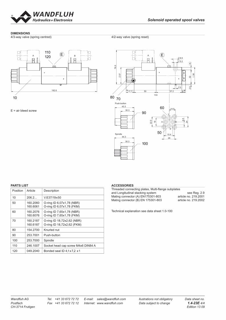
Postfach Fax +41 33 672 72 12 Internet: www.wandfl uh.com Data subject to change 1.4-23E 4/4
CH-3714 Frutigen Edition 13 09
Solenoid operated spool valves
PARTS LIST
Position Article Description
10 206.2... V.E37/19x50
50 160.2060
160.6061
O-ring ID 6,07x1,78 (NBR)
O-ring ID 6,07x1,78 (FKM)
60 160.2076
160.6076
O-ring ID 7,65x1,78 (NBR)
O-ring ID 7,65x1,78 (FKM)
70 160.2187
160.6187
O-ring ID 18,72x2,62 (NBR)
O-ring ID 18,72x2,62 (FKM)
80 154.2700 Knurled nut
90 253.7001 Push-button
100 253.7000 Spindle
110 246.1007 Socket head cap screw M4x6 DIN84 A
120 049.2040 Bonded seal ID 4,1 x 7,2 x 1
ACCESSORIES
Threaded connecting plates, Multi-fl ange subplates
and Longitudinal stacking system see Reg. 2.9
Mating connector (A) EN175301-803 article no. 219.2001
Mating connector (B) EN 175301-803 article no. 219.2002
Technical explanation see data sheet 1.0-100
E = air bleed screw
DIMENSIONS
4/3-way valve (spring centred) 4/2-way valve (spring reset)
A
32
6
76
.5
9.5
5.2
133
8.1 50
3
17.7
37
57.2
3
8
2.5
30.3
44.3
30.3
43.3
Push-button
Spindle
T
A B
P
22
.5
14.5
24
24
15.4
6.5
18
100
90
60
50
7080
10
EA B
192.6
10
E110
120
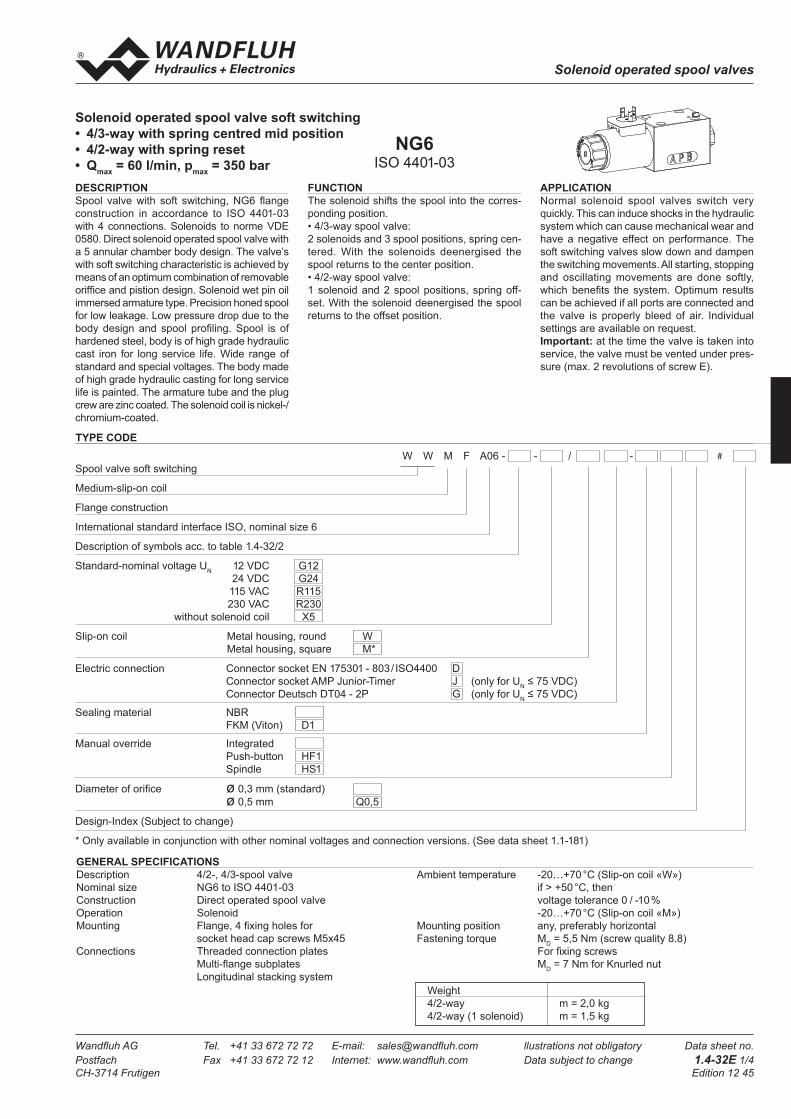
Wandfl uh AG Tel. +41 33 672 72 72 E-mail: sales@wandfl uh.com llustrations not obligatory Data sheet no.
Postfach Fax +41 33 672 72 12 Internet: www.wandfl uh.com Data subject to change 1.4-32E 1/4
CH-3714 Frutigen Edition 12 45
Solenoid operated spool valves
Solenoid operated spool valve soft switching
• 4/3-way with spring centred mid position
• 4/2-way with spring reset
• Qmax
= 60 l/min, pmax
= 350 bar
FUNCTION
The solenoid shifts the spool into the corres-
ponding position.
• 4/3-way spool valve:
2 solenoids and 3 spool positions, spring cen-
tered. With the solenoids deenergised the
spool returns to the center position.
• 4/2-way spool valve:
1 solenoid and 2 spool positions, spring off-
set. With the solenoid deenergised the spool
returns to the offset position.
APPLICATION
Normal solenoid spool valves switch very
quickly. This can induce shocks in the hydraulic
system which can cause mechanical wear and
have a negative effect on performance. The
soft switching valves slow down and dampen
the switching movements. All starting, stopping
and oscillating movements are done softly,
which benefi ts the system. Optimum results
can be achieved if all ports are connected and
the valve is properly bleed of air. Individual
settings are available on request.
Important: at the time the valve is taken into
service, the valve must be vented under pres-
sure (max. 2 revolutions of screw E).
DESCRIPTION
Spool valve with soft switching, NG6 fl ange
construction in accordance to ISO 4401-03
with 4 connections. Solenoids to norme VDE
0580. Direct solenoid operated spool valve with
a 5 annular chamber body design. The valve’s
with soft switching characteristic is achieved by
means of an optimum combination of removable
oriffi ce and pistion design. Solenoid wet pin oil
immersed armature type. Precision honed spool
for low leakage. Low pressure drop due to the
body design and spool profi ling. Spool is of
hardened steel, body is of high grade hydraulic
cast iron for long service life. Wide range of
standard and special voltages. The body made
of high grade hydraulic casting for long service
life is painted. The armature tube and the plug
crew are zinc coated. The solenoid coil is nickel-/
chromium-coated.
NG6ISO 4401-03
GENERAL SPECIFICATIONS
Description 4/2-, 4/3-spool valve
Nominal size NG6 to ISO 4401-03
Construction Direct operated spool valve
Operation Solenoid
Mounting Flange, 4 fi xing holes for
socket head cap screws M5x45
Connections Threaded connection plates
Multi-fl ange subplates
Longitudinal stacking system
TYPE CODE
Ambient temperature -20…+70 °C (Slip-on coil «W»)
if > +50 °C, then
voltage tolerance 0 / -10 %
-20…+70 °C (Slip-on coil «M»)
Mounting position any, preferably horizontal
Fastening torque MD = 5,5 Nm (screw quality 8.8)
For fi xing screws
MD = 7 Nm for Knurled nut
W W M F A06 - - / - # Spool valve soft switching
Medium-slip-on coil
Flange construction
International standard interface ISO, nominal size 6
Description of symbols acc. to table 1.4-32/2
Standard-nominal voltage UN 12 VDC G12
24 VDC G24
115 VAC R115
230 VAC R230
without solenoid coil X5
Slip-on coil Metal housing, round W
Metal housing, square M*
Electric connection Connector socket EN 175301 - 803 / ISO4400 D
Connector socket AMP Junior-Timer J (only for UN ≤ 75 VDC)
Connector Deutsch DT04 - 2P G (only for UN ≤ 75 VDC)
Sealing material NBR
FKM (Viton) D1
Manual override Integrated
Push-button HF1
Spindle HS1
Diameter of orifi ce ø 0,3 mm (standard)
ø 0,5 mm Q0,5
Design-Index (Subject to change)
* Only available in conjunction with other nominal voltages and connection versions. (See data sheet 1.1-181)
Weight
4/2-way m = 2,0 kg
4/2-way (1 solenoid) m = 1,5 kg

Wandfl uh AG Tel. +41 33 672 72 72 E-mail: sales@wandfl uh.com llustrations not obligatory Data sheet no.
Postfach Fax +41 33 672 72 12 Internet: www.wandfl uh.com Data subject to change 1.4-32E 2/4
CH-3714 Frutigen Edition 12 45
Solenoid operated spool valves
ELECTRICAL CONTROL
Construction Solenoid, wet pin push type, pressure tight
Standard-nominal voltage UN = 12 VDC
UN = 24 VDC
UN = 115 VAC∗
UN
= 230 VAC∗
AC = 50 to 60 Hz
∗ Rectifi er integrated in the coil, other
nominal voltages and nominal
performances on request
Voltage tolerance ±10% of nominal voltage
Protection class Connection version
to EN 60 529 D: IP 65
J: IP 66 only for UN ≤ 75 VDC
G: IP 67 and 69K only for UN ≤ 75 VDC
Relative duty factor 100% DF (see data sheet 1.1-430)
Switching cycles Since switching is damped and slow,
the switching frequency is of secondary
importance.
Operating life 107 (number of switching cycles, theoretically)
Connection/Power supply Over device plug connection
Coil versions: W.E45 / 23 x 50 (data sheet 1.1-182)
Other electrical specifi cations see data sheet 1.1-182 (W)
1.1-181 (M)
MANUAL OVERRIDE
- Integrated (–) Actuation pin integrated in the armature tube.
- Push-button (HF1) integrated in the knurled nut.
Actuation by pressing the pin
- Spindle (HS1) integrated in the knurled nut.
Actuation by turning the spindle (infi nitely variable valve actuation)
HYDRAULIC SPECIFICATIONS
Fluid Mineral oil, other fl uid on request
Contamination effi ciency ISO 4406:1999, classe 20/18/14
(Required fi ltration grade ß 10…16 ≥75)
refer to data sheet 1.0-50/2
Viscosity range 12 mm2/s…320 mm2/s
Fluid temperature -20…+70°C
Working pressure
in port P, A, B pmax
= 350 bar
Tank pressure
in port T pT max
= 200 bar
Max. volume fl ow Qmax
= 60 l/min, see characteristics
Leakage volume fl ow see characteristics
TYPE LIST / DESIGNATION OF SYMBOLS
4/2-way valve with spring reset Transitional functions
operation A-side operation B-side
4/3-way valve spring centred
a b
BA
P T
a b
BA
P T
o
a b
BA
P T
o
a b
BA
P T
o
a b
BA
P T
o
a b
BA
P T
a b
BA
P T
ab
BA
P T
a b
BA
P T
ab
BA
P T
ab
BA
P T
a b
BA
P T
a b
BA
P T
ab
BA
P T
a b
BA
P T
ab
BA
P T
ab
BA
P T
A B 3
A C B
A D B
B E A
A F B
A G B
A B 1
A C 1
A D 1
B E 1
A F 1
A G 1
A B 2
C B 2
D B 2
E A 2
F B 2
G B 2
a b
BA
P T
o

Wandfl uh AG Tel. +41 33 672 72 72 E-mail: sales@wandfl uh.com llustrations not obligatory Data sheet no.
Postfach Fax +41 33 672 72 12 Internet: www.wandfl uh.com Data subject to change 1.4-32E 3/4
CH-3714 Frutigen Edition 12 45
Solenoid operated spool valves
∆p = f (Q) Pressure drop volume fl ow characteristics QL = f (p) Leakage volume fl ow characteristics per control edge
CHARACTERSISTICS Oilviscosity υ = 30 mm2/s
p = f (Q) Performance limits with standard voltage -10%
SHIFTING TIMES Infl uence of soft switching
Measured with WWMFA06-ACB-G24 at Q = 30 l/min compared with WDMFA06-ACB-G24
Solenoid energised Orifi ces in valve body infl uence shifting time
Solenoid deenergised
(Pressure mesured in P)
(Pressure mesured in P)
Volume fl ow direction
P - A P - B P - T A - T B - T
AB1 / AB2 1 1 - 1 1
ACB 4 4 - 4 4
ADB 3 3 - 2 2
Pressure drop
Curve noSymbol
350
300
250
200
150
100
50
00 10 20 30 40 50 60
AB1, AB2
ADB, ACBK1041
2
4
1
3
p [bar]
0 10 20 30 40 50 60
20
15
10
5
0
K1042 180160140120100806040200
0 50 100 150 200 250 300 350
[cm3 /min]K1043
Standard valve
Soft-switching valve Orifice 0,5 mm
Soft-switching valve Orifice 0,3 mm
K1051
Standard valve
Soft-switching valve
Orifice 0,5
Soft-switching valve Orifice 0,3 mm
K1052
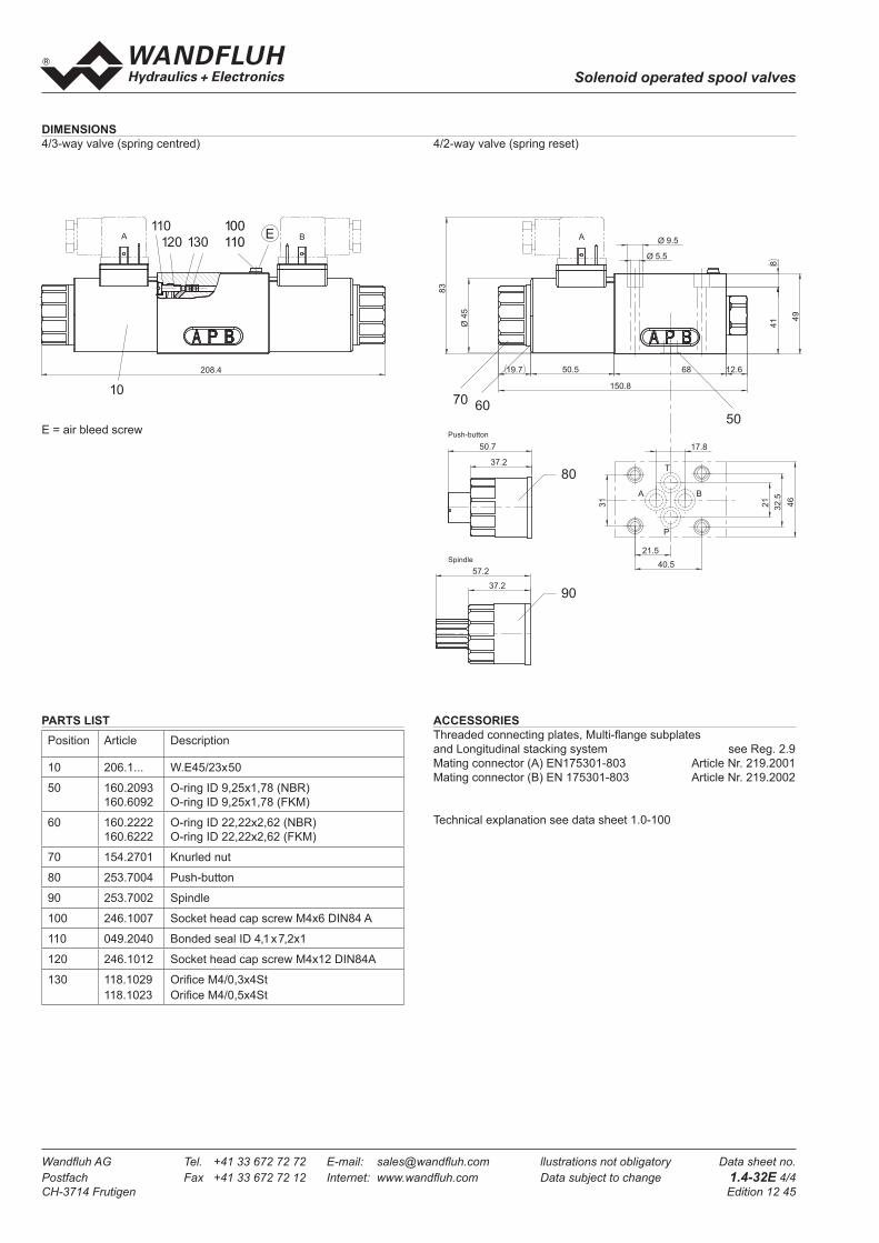
Wandfl uh AG Tel. +41 33 672 72 72 E-mail: sales@wandfl uh.com llustrations not obligatory Data sheet no.
Postfach Fax +41 33 672 72 12 Internet: www.wandfl uh.com Data subject to change 1.4-32E 4/4
CH-3714 Frutigen Edition 12 45
Solenoid operated spool valves
PARTS LIST
E = air bleed screw
DIMENSIONS
4/3-way valve (spring centred) 4/2-way valve (spring reset)
Position Article Description
10 206.1... W.E45/23x50
50 160.2093
160.6092
O-ring ID 9,25x1,78 (NBR)
O-ring ID 9,25x1,78 (FKM)
60 160.2222
160.6222
O-ring ID 22,22x2,62 (NBR)
O-ring ID 22,22x2,62 (FKM)
70 154.2701 Knurled nut
80 253.7004 Push-button
90 253.7002 Spindle
100 246.1007 Socket head cap screw M4x6 DIN84 A
110 049.2040 Bonded seal ID 4,1 x 7,2x1
120 246.1012 Socket head cap screw M4x12 DIN84A
130 118.1029
118.1023
Orifi ce M4/0,3x4St
Orifi ce M4/0,5x4St
ACCESSORIES
Threaded connecting plates, Multi-fl ange subplates
and Longitudinal stacking system see Reg. 2.9
Mating connector (A) EN175301-803 Article Nr. 219.2001
Mating connector (B) EN 175301-803 Article Nr. 219.2002
Technical explanation see data sheet 1.0-100
A B
208.4
10
E100
110120
110
130
46
17.8
21
32.5
31
40.5
21.5
B
T
P
A
A
83
Ø 5.5
Ø 9.5
41
8
Ø45
19.7 50.5 12.6
150.8
49
68
506070
10
37.2
50.7
37.2
57.2
90
80
Push-button
Spindle

Wandfl uh AG Tel. +41 33 672 72 72 E-mail: sales@wandfl uh.com llustrations not obligatory Data sheet no.
Postfach Fax +41 33 672 72 12 Internet: www.wandfl uh.com Data subject to change 1.4-40E 1/4
CH-3714 Frutigen Edition 06 20
Solenoid operated spool valves
Solenoid operated spool valve with soft switching
• 4/2-way with 2 solenoids
• 4/3-way with spring centred mid position
• 4/2-way with spring reset
• Qmax
= 80 l/min, pmax
= 350 bar
CONTENT
GENERAL SPECIFICATIONS ......................1
HYDRAULIC SPECIFICATIONS ..................1
ELECTRICAL CONTROL .............................2
SOLENOID DESCRIPTION .........................2
TYPE LIST /
DESIGNATIONS OF SYMBOLS ..................2
CHARACTERISTICS ....................................3
DIMENSIONS ...............................................3
SHIFTING TIMES .........................................4
PARTS LIST .................................................4
ACCESSORIES............................................4
DESCRIPTION
Spool valve with soft switching, NG10 fl ange
construction in accordance to ISO 4401-05 with
4 connections. Solenoids to norme VDE 0580.
Direct solenoid operated spool valve with a 5
annular chamber body design. The valve's
with soft switching characteristic is achieved
by means of an optimum combination of remo-
vable oriffi ce and pistion design. Solenoid wet
pin oil immersed armature type. Precision
honed spool for low leakage. Low pressure
drop due to the body design and spool profi -
ling. Spool is of hardened steel, body is of high
grade hydraulic cast iron for long service life.
Wide range of standard and special voltages
in 2 solenoid versions. The body made of high
grade hydraulic casting for long service life is
painted. The cover and the solenoid are zinc
coated.
APPLICATION
Normal solenoid spool valves switch very
quickly. This can induce shocks in the hydraulic
system which can cause mechanical wear and
have a negative effect on performance. The
soft switching valves slow down and dampen
the switching movements. All starting, stopping
and oscillating movements are done softly,
which benefi ts the system. Optimum results
can be achieved if all ports are connected and
the valve is properly bleed of air. Individual
settings are available on request.
Important: at the time the valve is taken into
service, the valve must be vented under pres-
sure (max. 2 revolutions of screw E).
TYPE CODE
A W 4 - / #
International mounting interface ISO
Medium-solenoid M
Super-solenoid S
Soft switching
Number of control ports
Description of symbols acc. to table 1.4-40/2
Standard- nominal voltage UN: 12 VDC G12 110 VAC R110
24 VDC G24 115 VAC R115
230 VAC R230
Orifi ce area: Ø 0,5 Standard type no remark
Ø 0,7 0,7
Ø 0,9 0,9
Design-Index (Subject to change)
GENERAL SPECIFICATIONS
Description 4/2-, 4/3-way spool valve
Nominal size NG10 to ISO 4401-05
Construction Direct operated spool valve
Operations Solenoid
Mounting Flange
4 fi xing holes for
socket head cap screw M6 x 65
Connections Threaded connection plates
Multi-fl ange subplates
Longitudinal stacking system
Ambient temperature -20...+50 °C
Mounting position any, preferably horizontal
Fastening torque MD= 9,5 Nm (screw quality 8.8)
Weight:
4/2-way (2 solenoid) m = 6,0 kg
4/3-way m = 6,0 kg
4/2-way (1 solenoid) m = 4,5 kg
HYDRAULIC SPECIFICATIONS
Fluid Mineral oil, other fl uid on request
Contamination effi ciency ISO 4406:1999, class 18/16/13
(Required fi ltration grade ß 6...10≥75)
refer to data sheet 1.0-50/2
Viscosity range 12 mm2/s...320 mm2/s
Fluid temperature -20...+70 °C
Working pressure
in port P, A, B pmax
= 350 bar
Tank pressure
in port T Medium: pmax
= 160 bar
Super: pmax
= 200 bar
Max. volume fl ow Qmax
= 80 l/min, see characteristics
Leakage volume fl ow see characteristics
FUNCTION
The solenoid shifts the spool into the corres-
ponding position.
• 4/2-way
Two solenoids and 2 switch settings. 100% ED
holds the switch setting on the solenoid (no
mechanical detente).
• 4/3-way spool valve:
2 solenoids and 3 spool positions, spring cen-
tered. With the solenoids deenergised the
spool returns to the center position.
• 4/2-way spool valve:
1 solenoid and 2 spool positions, spring off-
set. With the solenoid deenergised the spool
returns to the offset position.
NG10ISO 4401-05

Wandfl uh AG Tel. +41 33 672 72 72 E-mail: sales@wandfl uh.com llustrations not obligatory Data sheet no.
Postfach Fax +41 33 672 72 12 Internet: www.wandfl uh.com Data subject to change 1.4-40E 2/4
CH-3714 Frutigen Edition 06 20
Solenoid operated spool valves
a b
BA
P T
a b
BA
P T
o
a b
BA
P T
o
a b
BA
P T
o
a b
BA
P T
o
a b
BA
P T
a b
BA
P T
ab
BA
P T
a b
BA
P T
ab
BA
P T
ab
BA
P T
a b
BA
P T
a b
BA
P T
ab
BA
P T
a b
BA
P T
ab
BA
P T
ab
BA
P T
J 1 0 0
D 1 0 1
D 1 0 2
D 1 0 3
D 1 0 4
D 1 0 5
Z 1 0 0 a
Z 1 0 1 a
Z 1 0 2 a
Z 1 0 3 a
Z 1 0 4 a
Z 1 0 5 a
Z 1 0 0 b
Z 1 0 1 b
Z 1 0 2 b
Z 1 0 3 b
Z 1 0 4 b
Z 1 0 5 b
a b
BA
P T
o
ELECTRICAL CONTROL
Construction Solenoid, wet pin push type, pressure
tight
Standard-nominal voltage UN = 12 VDC, 24 VDC
UN = 110 VAC∗, 115 VAC∗, 230 VAC∗
AC = 50 to 60 Hz
∗ Rectifi er integrated in the plug, other
nominal voltages and nominal
performances on request.
Voltage tolerance ±10 % of nominal voltage
Protection class IP 65 to EN 60 529
Relative duty factor 100 % DF (see data sheet 1.1-430)
Switching cycles Since switching is damped and slow, the
switching frequency is of secondary
importance.
Operating life 107 (number of switching cycles, theoretically)
Connection / Power supply Over device plug connection to ISO 4400/
DIN 43 650, (2P+E), other connections on
request.
SOLENOID DESCRIPTION
With respect to the selection of the solenoid, the following statements
are important:
– The solenoid is the most expensive component of the solenoid
spool valve.
– For this reason, it is not economical to use the same solenoid for
all applications.
– Depending on the application, sales area, and customer, the
requirements for solenoid spool valves and solenoids differ very
considerably.
– In order to be able to offer the customer an optimum, we can supp-
ly our solenoid spool valves NG10 in 2 different versions:
– Medium SIN60V (data sheet 1.1-145)
– Super SIS60V (data sheet 1.1-150)
TYPE LIST / DESIGNATION OF SYMBOLS
4/3-way valve spring centered
4/2-way valve 4/2-way valve with spring reset Transitional functions
with 2 solenoids operation A-side operation B-side

Wandfl uh AG Tel. +41 33 672 72 72 E-mail: sales@wandfl uh.com llustrations not obligatory Data sheet no.
Postfach Fax +41 33 672 72 12 Internet: www.wandfl uh.com Data subject to change 1.4-40E 3/4
CH-3714 Frutigen Edition 06 20
Solenoid operated spool valves
Volume fl ow direction
P - A P - B P - T A - T B - T
Z100/J100 2 2 - 2 2
D101/Z101 2 2 - 2 2
D102/Z102 2 2 - 1 1
D103/Z103 3 3 2 3 3
D104/Z104 1 1 - 1 1
D105/Z105 1 1 - 2 2
Pressure drop
curve no.Symbol
9 08 0 3 5
E
E
A B
1 0
2 0
3 0
4 0 6 0
7 0
5 0
E
E
A
T
A B
P
T o
2 6 7 , 4
60
62
1 7 , 59 38 1 , 5
1 9 8
60
1 0 , 5
7(
)
55
6 , 5
100
5 4
2 0 , 8
4 8
46
1,5
16,8
9,7
CHARACTERISTICS Oil viscosity υ = 30 mm2/s
p = f (Q) Performance limits with standard voltage -10 %
Medium Super
∆p = f (Q) Pressure drop volume fl ow characteristics
QL = f (p) Leakage volume fl ow characteristics per control edge
E = air bleed screw
DIMENSIONS
4/3-way valve (spring centered) 4/2-way valve (spring reset)
4/2-way valve (with 2 solenoids)
0 800
Q [l/min]
K0394
p [bar]Z102/D102
Z104/D104
50100150200250300350
10 20 30 40 50 60 70
J100/Z105/D105Z100/Z101/D101Z103/D103
0 800
Q [l/min]
K0395
p [bar]
Z100
Z104/D104
50100150200250300350
10 20 30 40 50 60 70
J100/Z105/D105Z101/D101
Z103/D103
Z102/D102
0800
K0396
10 30 50 70 Q [l/min]20 40 60
4
8
12
16
1
2
3p [bar]
p [bar]
K0397
Q [cm /min]3
0 50 100 150 200 250 300 3500
40
80
120
160
200

Wandfl uh AG Tel. +41 33 672 72 72 E-mail: sales@wandfl uh.com llustrations not obligatory Data sheet no.
Postfach Fax +41 33 672 72 12 Internet: www.wandfl uh.com Data subject to change 1.4-40E 4/4
CH-3714 Frutigen Edition 06 20
Solenoid operated spool valves
Position Article Description
10 260.8 ... Medium-solenoid SIN60V
260.9 ... Super-solenoid SIS60V
20 239.2033 Plug HB0 (incl. seal)
30 219.2001 Plug A (grey)
35 219.2002 Plug B (black)
40 059.2201 Cover Medium
059.2203 Cover Super
50 246.3190 Socket head cap screw M6x90 DIN912
60 246.3121 Socket head cap screw M6x20 DIN912
70 160.2140 O-ring ID 14,00x1,78
80 246.2006 Socket head cap screw M5x6 DIN84 A
90 049.2050 Bonded seal ID 5,7x10x1
SHIFTING TIMES Infl uence of orifi ces on shifting
Mesured with AMW4D61-G24 Flow Q = 7 l/min
Solenoid energised Orifi ces in valve body infl uence shifting time
Solenoid deenergised
ACCESSORIES
Threaded connecting plates, Multi-fl ange subplates and
Longitudinal stacking system see Reg. 2.9
PARTS LIST
Technical explanation see data sheet 1.0-100
0
0
K0602
t [s]0,2 0,40,1 0,3 0,5
24
40
60
80
0,6 0,7 0,8 0,9 1,0
100
p [bar]
U [V]
0
20
(Pressure mesured in P)
no orifice
Orifice 0,9 Orifice 0,7
Orifice 0,5
0
0
K0603
t [s]0,2 0,40,1 0,3 0,5
24
40
60
80
0,6 0,7 0,8 0,9 1,0
100
p [bar]
U [V]
0
20
Orifice 0,7
Orifice 0,5
Orifice 0,9
no orifice
(Pressure mesured in P)
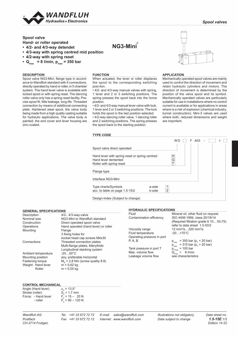
Spool valves
Wandfl uh AG Tel. +41 33 672 72 72 E-mail: sales@wandfl uh.com Illustrations not obligatory Data sheet no.
Postfach Fax +41 33 672 72 12 Internet: www.wandfl uh.com Data subject to change 1.5-15E 1/3
CH-3714 Frutigen Edition 14 22
Spool valve
Hand- or roller operated
• 4/2- and 4/3-way detendet
• 4/3-way with spring centred mid position
• 4/2-way with spring reset
• Qmax
= 8 l/min, pmax
= 350 bar
FUNCTION
When actuated, the lever or roller displaces
the spool to the corresponding switching
posi-tion.
• 4/2- and 4/3-way manual valves with spring,
1 lever and 2 or 3 switching positions. The
spring presses the spool back into the home
position.
• 4/2- and 4/3-way manual lever valve with lock,
1 lever and 2 or 3 switching positions. The lock
holds the spool in the last position selected.
• 4/2-way dancing roller valve, 1 dancing roller
and 2 switching positions. The spring presses
the spool back to the starting position.
APPLICATION
Mechanically operated spool valves are mainly
used to control the direction of movement and
retain hydraulic cylinders and motors. The
direction of movement is determined by the
position of the valve spool and its symbol.
Mechanically operated valves are particularly
suitable for use in installations where no control
current is available or for applications in areas
where is a risk of explosion (chemical industry,
tunnel construction). Mini-3 valves are used
where both, reduced dimensions and weight
are important.
DESCRIPTION
Spool valve NG3-Mini, fl ange type in accord-
ance to Wandfl uh standard with 4 connections,
directly operated by hand or roller, in 5 chamber
system. The hand lever valve is available with
locked spool or with spring reset. The dancing
roller valve only has a spring reset facility. Pre-
cise spool fi t, little leakage, long life. Threaded
connection by means of additional connecting
plate. Hardened steel spool, the valve body
being made from a high quality casting suitable
for hydraulic applications. The valve body is
painted, the end cover and lever housing are
zinc-coated.
GENERAL SPECIFICATIONS
Description 4/2-, 4/3-way-valve
Nominal size NG3-Mini to Wandfl uh standard
Construction Direct operated spool valve
Operations Hand operated (hand lever) or roller
Mounting Flange
3 fi xing holes for
socket head cap screws M4x30
Connections Threaded connection plates
Multi-fl ange plates, Manyfolds
Longitudinal stacking system
Ambient temperature -20…50°C
Mounting position any, preferable horizontal
Fastening torque MD = 2,8 Nm (screw quality 8.8)
Weight: Hand lever m = 0,62 kg
Roller m = 0,55 kg
HYDRAULIC SPECIFICATIONS
Fluid Mineral oil, other fl uid on request
Contamination effi ciency ISO 4406:1999, class 20/18/14
(Required fi ltration grade ß 10…16≥75)
refer to data sheet 1.0-50/2
Viscosity range 12 mm2/s…320 mm2/s
Fluid temperature -20…+70°C
Operating pressure in port
P, A, B pmax
= 350 bar (pT < 20 bar)
pmax
= 315 bar (pT > 20 bar)
Tank pressure in port T pTmax
= 100 bar
Max. volume fl ow Qmax
= 8 l/min
Leakage volume fl ow see characteristics
CONTROL MECHANICAL
Angle (Hand lever) αb = 13,5°
Stroke (roller) Sb = 1,7 mm
Force: - Hand lever Fb = 15 – 20 N
- roller Fb = 90 – 120 N
W D F A03 - #
Spool valve direct operated
Hand lever with spring reset or spring centred H
Hand lever dentented G
Roller with spring reset T
Flange type
Interface NG3-Mini
Type charts/Symbols a-side 1
acc. to table on page 1.5-15/2 b-side 2
Design-Index (Subject to change)
TYPE CODE
NG3-Mini®

Spool valves
Wandfl uh AG Tel. +41 33 672 72 72 E-mail: sales@wandfl uh.com Illustrations not obligatory Data sheet no.
Postfach Fax +41 33 672 72 12 Internet: www.wandfl uh.com Data subject to change 1.5-15E 2/3
CH-3714 Frutigen Edition 14 22
TYPE LIST / DESIGNATION OF SYMBOLS
4/3-way valve 4/2-way valve Transitional functions
(only by hand lever operation)
4/2-way valve Transitional functions
CHARACTERSISTICS Oilviscosity υ = 30 mm2/s
p = f (Q) Performance limits QL = f (p) Leakage volume fl ow characteristics
per control edge
∆p = f (Q) Pressure drop volume fl ow characteristics
Volume fl ow direction
P - A P - B P - T A - T B - T
AB1/AB2 4 4 - 3 3
ACB1/ACB2/AC1/CB2 4 4 - 2 2
ADB1/ADB2/AD1/DB2 3 3 - 2 2
BEA1/BEA2/BE1/EA2 6 6 4 5 5
AFB1/AFB2/AF1/FB2 2 2 1 2 2
AGB1/AGB2/AG1/GB2 3 3 - 3 3
Pressure drop curve no.
Symbol
080
K0528
Q [l/min]2 4 6 71 3 5
4
8
12
16
p [bar]
6
5
4
321
a b
BA
P T
a b
BA
P T
o
a b
BA
P T
o
a b
BA
P T
o
a b
BA
P T
o
a b
BA
P T
a b
BA
P T
ab
BA
P T
a b
BA
P T
ab
BA
P T
ab
BA
P T
a b
BA
P T
ab
BA
P T
a b
BA
P T
ab
BA
P T
ab
BA
P T
AB1
ACB1
ADB1
BEA1
AFB1
AGB1
AB2
AC1
AD1
BE1
AF1
AG1
CB2
DB2
EA2
FB2
GB2
a b
BA
P T
o
ACB2
ADB2
BEA2
AFB2
AGB2
K0263
BEA
AB1/ACB/ADB/AFB/AGB

Spool valves
Wandfl uh AG Tel. +41 33 672 72 72 E-mail: sales@wandfl uh.com Illustrations not obligatory Data sheet no.
Postfach Fax +41 33 672 72 12 Internet: www.wandfl uh.com Data subject to change 1.5-15E 3/3
CH-3714 Frutigen Edition 14 22
DIMENSIONS
Roller Hand lever
PARTS LIST ACCESSORIES
Threaded connection plates, Multi fl ange plates register 2.9
Position Article Description
10 081.0018 Grip
20 096.2008 Lever
30 034.1106 Bolt
40 253.1100 Mechanical control head BTIII
50 246.0126 Socket head cap screw M3x25 DIN 912
60 246.0151 Socket head cap screw M3x50 DIN 912
70 246.0131 Socket head cap screw M3x30 DIN 912
80 238.1100 Plug screw galv. M10x1 DIN 7604A
(by spring centred version)
239.7104 Plug screw
(by dedented version)
90 049.1100 Cop. seal ring NG10x13,5x1 DIN 7603
(only by dedented version)
100 221.1166 Spring tension pin ∅ 2x16 DIN 6325
110 221.1382 Spring tension pin ∅ 4x24 DIN 6325
120 160.2045 O-ring ID4,50x1,50 Technical explanation see data sheet 1.0-100
120
100
40
70
Wide = 8
Breite = 8
Largeur = 8
4,2
7,5
26 38 20
48,5
117,5
29
5(
)25 3
0
10
2030
110
60
80,90
5010
6
382619
35,5
5(
)25
7,5
109
20
29
30
4,2
16
A B
P
T
T0
11
21
10
20
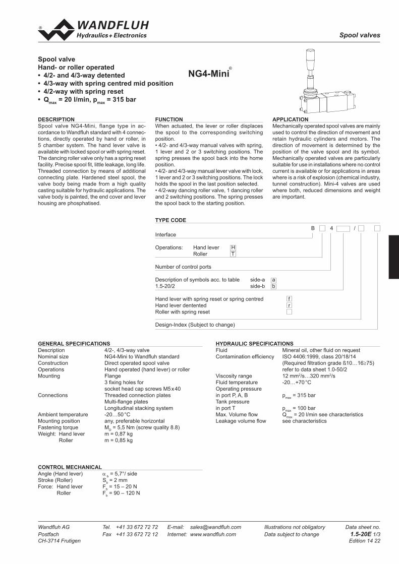
Spool valves
Wandfl uh AG Tel. +41 33 672 72 72 E-mail: sales@wandfl uh.com Illustrations not obligatory Data sheet no.
Postfach Fax +41 33 672 72 12 Internet: www.wandfl uh.com Data subject to change 1.5-20E 1/3
CH-3714 Frutigen Edition 14 22
Spool valve
Hand- or roller operated
• 4/2- and 4/3-way detented
• 4/3-way with spring centred mid position
• 4/2-way with spring reset
• Qmax
= 20 l/min, pmax
= 315 bar
CONTROL MECHANICAL
Angle (Hand lever) α b = 5,7°/ side
Stroke (Roller) Sb = 2 mm
Force: Hand lever Fb = 15 – 20 N
Roller Fb = 90 – 120 N
GENERAL SPECIFICATIONS
Description 4/2-, 4/3-way valve
Nominal size NG4-Mini to Wandfl uh standard
Construction Direct operated spool valve
Operations Hand operated (hand lever) or roller
Mounting Flange
3 fi xing holes for
socket head cap screws M5 x 40
Connections Threaded connection plates
Multi-fl ange plates
Longitudinal stacking system
Ambient temperature -20…50 °C
Mounting position any, preferable horizontal
Fastening torque MD = 5,5 Nm (screw quality 8.8)
Weight: Hand lever m = 0,87 kg
Roller m = 0,85 kg
HYDRAULIC SPECIFICATIONS
Fluid Mineral oil, other fl uid on request
Contamination effi ciency ISO 4406:1999, class 20/18/14
(Required fi ltration grade ß10…16≥75)
refer to data sheet 1.0-50/2
Viscosity range 12 mm2/s…320 mm2/s
Fluid temperature -20…+70 °C
Operating pressure
in port P, A, B pmax
= 315 bar
Tank pressure
in port T pmax
= 100 bar
Max. Volume fl ow Qmax
= 20 l/min see characteristics
Leakage volume fl ow see characteristics
FUNCTION
When actuated, the lever or roller displaces
the spool to the corresponding switching
position.
• 4/2- and 4/3-way manual valves with spring,
1 lever and 2 or 3 switching positions. The
spring presses the spool back into the home
position.
• 4/2- and 4/3-way manual lever valve with lock,
1 lever and 2 or 3 switching positions. The lock
holds the spool in the last position selected.
• 4/2-way dancing roller valve, 1 dancing roller
and 2 switching positions. The spring presses
the spool back to the starting position.
APPLICATION
Mechanically operated spool valves are mainly
used to control the direction of movement and
retain hydraulic cylinders and motors. The
direction of movement is determined by the
position of the valve spool and its symbol.
Mechanically operated valves are particularly
suitable for use in installations where no control
current is available or for applications in areas
where is a risk of explosion (chemical industry,
tunnel construction). Mini-4 valves are used
where both, reduced dimensions and weight
are important.
DESCRIPTION
Spool valve NG4-Mini, flange type in ac-
cordance to Wandfl uh standard with 4 connec-
tions, directly operated by hand or roller, in
5 chamber system. The hand lever valve is
available with locked spool or with spring reset.
The dancing roller valve only has a spring reset
facility. Precise spool fi t, little leakage, long life.
Threaded connection by means of additional
connecting plate. Hardened steel spool, the
valve body being made from a high quality
casting suitable for hydraulic applications. The
valve body is painted, the end cover and lever
housing are phosphatised.
TYPE CODE
NG4-Mini®
B 4 /
Interface
Operations: Hand lever H
Roller T
Number of control ports
Description of symbols acc. to table side-a a
1.5-20/2 side-b b
Hand lever with spring reset or spring centred f
Hand lever dentented r
Roller with spring reset
Design-Index (Subject to change)

Spool valves
Wandfl uh AG Tel. +41 33 672 72 72 E-mail: sales@wandfl uh.com Illustrations not obligatory Data sheet no.
Postfach Fax +41 33 672 72 12 Internet: www.wandfl uh.com Data subject to change 1.5-20E 2/3
CH-3714 Frutigen Edition 14 22
TYPE LIST / DESIGNATION OF SYMBOLS
CHARACTERSISTICS Oilviscosity υ = 30 mm2/s
p = f (Q) Performance limits QL = f (p) Leakage volume fl ow characteristics
per control edge
∆p = f (Q) Pressure drop volume fl ow characteristics
Volume fl ow direction
P - A P - B P - T A - T B - T
Z40 5 5 - 2 2
D41/Z41 5 5 - 2 2
D42/Z42 5 5 - 2 2
D43/Z43 4 4 6 1 1
D44/Z44 4 4 3 1 1
D45/Z45 4 4 - 2 2
Pressure drop
curve no.Symbol
00
p [bar]K0099
Q [l/m in]5 1510 20
5
1 0
1 5
2 0
2 5
3 0 6
54321
a b
BA
P T
a b
BA
P T
o
a b
BA
P T
o
a b
BA
P T
o
a b
BA
P T
o
a b
BA
P T
ab
BA
P T
a b
BA
P T
ab
BA
P T
ab
BA
P T
a b
BA
P T
ab
BA
P T
a b
BA
P T
ab
BA
P T
ab
BA
P T
D41a
D42a
D43a
D44a
D45a
Z41a
Z42a
Z43a
Z44a
Z45a
Z41b
Z42b
Z43b
Z44b
Z45b
o
D41b
D42b
D43b
D44b
D45b
a b
BA
P T
Z40a Z40ba b
BA
P T
00
p [bar]K0098
Q [l/m in]5 1510 20
1 0 0
2 0 0
3 0 0
Z40
Z41/D41Z41/D42
Z45/D45
Z43/D43
Z44/D44
K0263_1
D43
Z40/D41/D42/D44/D45
4/2-way valve Transitional functions
4/3-way valve 4/2-way valve Transitional functions
(only by hand lever operation)
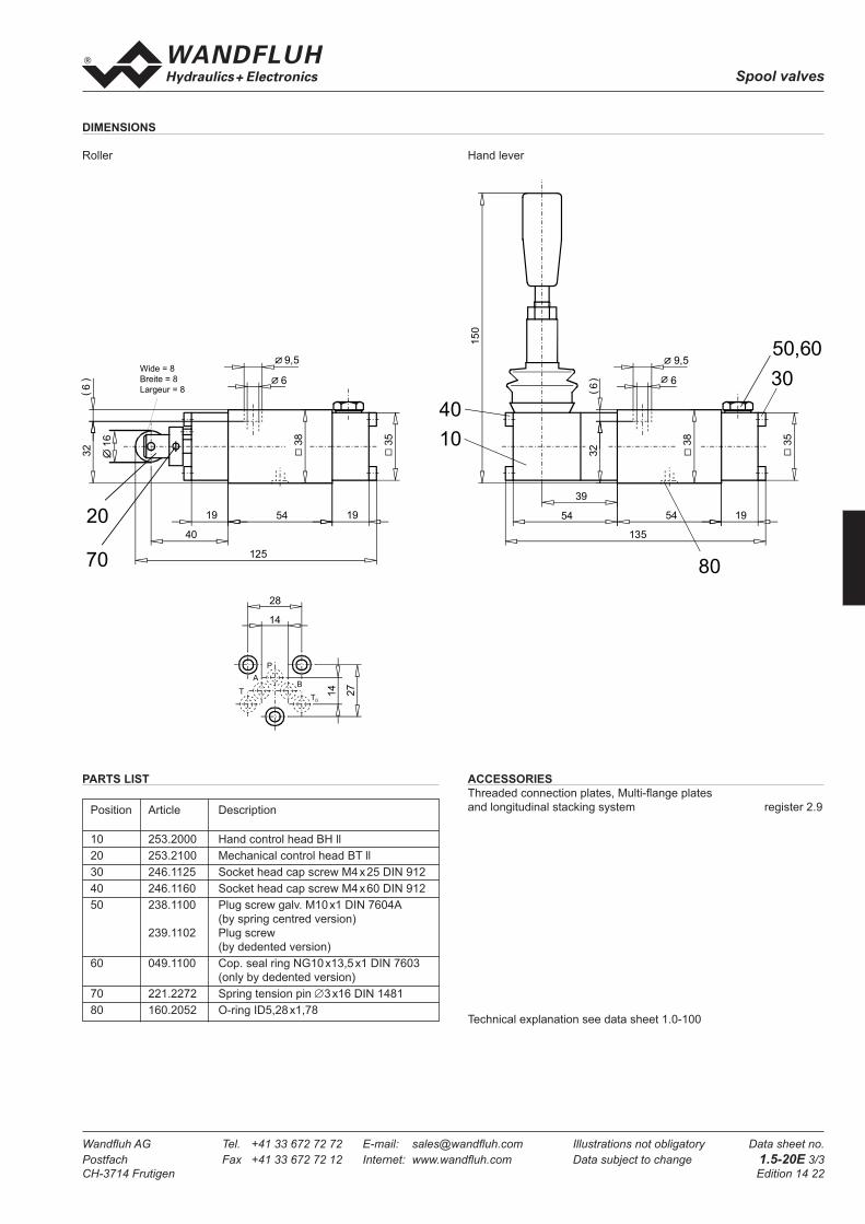
Spool valves
Wandfl uh AG Tel. +41 33 672 72 72 E-mail: sales@wandfl uh.com Illustrations not obligatory Data sheet no.
Postfach Fax +41 33 672 72 12 Internet: www.wandfl uh.com Data subject to change 1.5-20E 3/3
CH-3714 Frutigen Edition 14 22
PARTS LIST
Position Article Description
10 253.2000 Hand control head BH ll
20 253.2100 Mechanical control head BT ll
30 246.1125 Socket head cap screw M4 x 25 DIN 912
40 246.1160 Socket head cap screw M4 x 60 DIN 912
50 238.1100 Plug screw galv. M10 x1 DIN 7604A
(by spring centred version)
239.1102 Plug screw
(by dedented version)
60 049.1100 Cop. seal ring NG10 x13,5 x1 DIN 7603
(only by dedented version)
70 221.2272 Spring tension pin ∅3 x16 DIN 1481
80 160.2052 O-ring ID5,28 x1,78Technical explanation see data sheet 1.0-100
ACCESSORIES
Threaded connection plates, Multi-fl ange plates
and longitudinal stacking system register 2.9
DIMENSIONS
Roller Hand lever
14
28
14
27
T
A
P
B
T0
1954
39
54
135
15
0
32
6(
) 6
9,5
35
3810
30
40
50,60
80
195419
40
125
32
6(
) 6
9,5
35
38
20
70
16
Wide = 8
Breite = 8
Largeur = 8
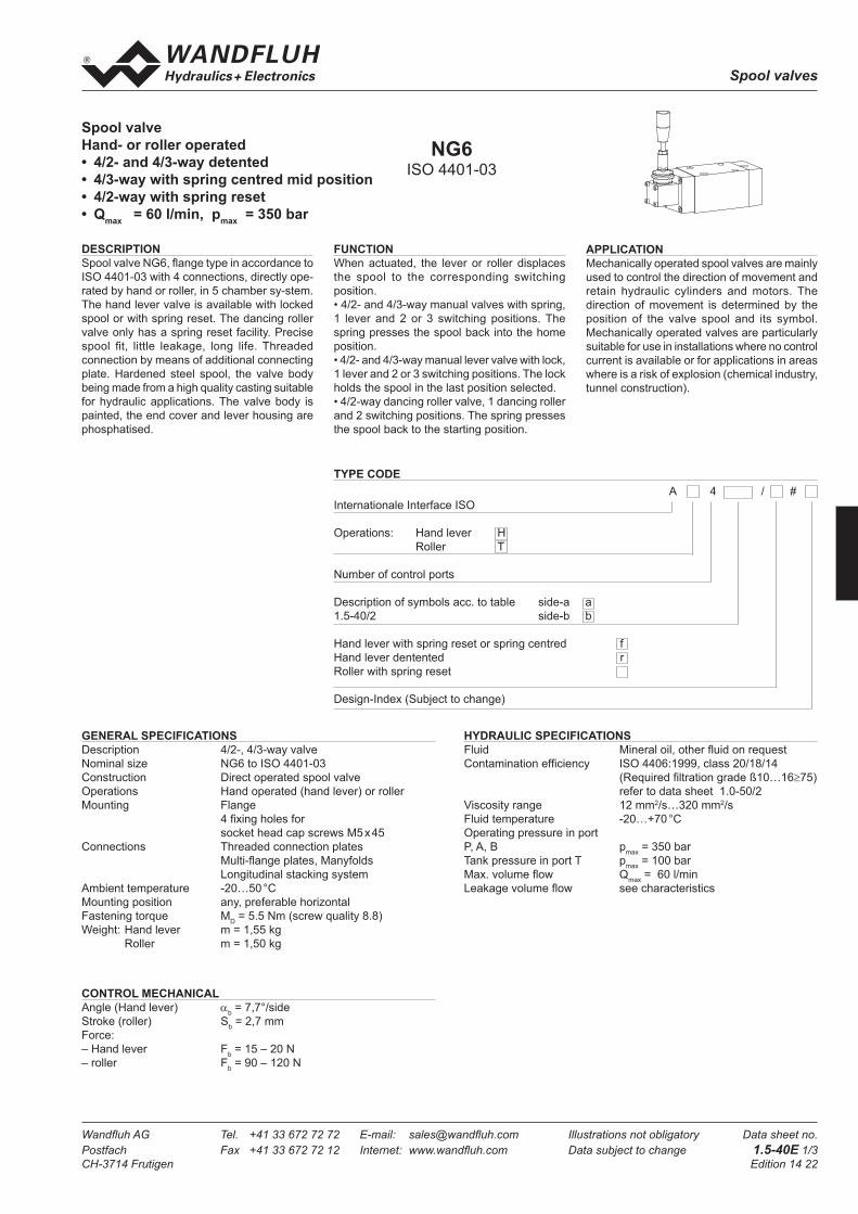
Spool valves
Wandfl uh AG Tel. +41 33 672 72 72 E-mail: sales@wandfl uh.com Illustrations not obligatory Data sheet no.
Postfach Fax +41 33 672 72 12 Internet: www.wandfl uh.com Data subject to change 1.5-40E 1/3
CH-3714 Frutigen Edition 14 22
FUNCTION
When actuated, the lever or roller displaces
the spool to the corresponding switching
position.
• 4/2- and 4/3-way manual valves with spring,
1 lever and 2 or 3 switching positions. The
spring presses the spool back into the home
position.
• 4/2- and 4/3-way manual lever valve with lock,
1 lever and 2 or 3 switching positions. The lock
holds the spool in the last position selected.
• 4/2-way dancing roller valve, 1 dancing roller
and 2 switching positions. The spring presses
the spool back to the starting position.
Spool valve
Hand- or roller operated
• 4/2- and 4/3-way detented
• 4/3-way with spring centred mid position
• 4/2-way with spring reset
• Qmax
= 60 l/min, pmax
= 350 bar
TYPE CODE
CONTROL MECHANICAL
Angle (Hand lever) αb = 7,7°/side
Stroke (roller) Sb = 2,7 mm
Force:
– Hand lever Fb = 15 – 20 N
– roller Fb = 90 – 120 N
GENERAL SPECIFICATIONS
Description 4/2-, 4/3-way valve
Nominal size NG6 to ISO 4401-03
Construction Direct operated spool valve
Operations Hand operated (hand lever) or roller
Mounting Flange
4 fi xing holes for
socket head cap screws M5 x 45
Connections Threaded connection plates
Multi-fl ange plates, Manyfolds
Longitudinal stacking system
Ambient temperature -20…50 °C
Mounting position any, preferable horizontal
Fastening torque MD = 5.5 Nm (screw quality 8.8)
Weight: Hand lever m = 1,55 kg
Roller m = 1,50 kg
HYDRAULIC SPECIFICATIONS
Fluid Mineral oil, other fl uid on request
Contamination effi ciency ISO 4406:1999, class 20/18/14
(Required fi ltration grade ß10…16≥75)
refer to data sheet 1.0-50/2
Viscosity range 12 mm2/s…320 mm2/s
Fluid temperature -20…+70 °C
Operating pressure in port
P, A, B pmax
= 350 bar
Tank pressure in port T pmax
= 100 bar
Max. volume fl ow Qmax
= 60 l/min
Leakage volume fl ow see characteristics
A 4 / #
Internationale Interface ISO
Operations: Hand lever H
Roller T
Number of control ports
Description of symbols acc. to table side-a a
1.5-40/2 side-b b
Hand lever with spring reset or spring centred f
Hand lever dentented r
Roller with spring reset
Design-Index (Subject to change)
APPLICATION
Mechanically operated spool valves are mainly
used to control the direction of movement and
retain hydraulic cylinders and motors. The
direction of movement is determined by the
position of the valve spool and its symbol.
Mechanically operated valves are particularly
suitable for use in installations where no control
current is available or for applications in areas
where is a risk of explosion (chemical industry,
tunnel construction).
DESCRIPTION
Spool valve NG6, fl ange type in accordance to
ISO 4401-03 with 4 connections, directly ope-
rated by hand or roller, in 5 chamber sy-stem.
The hand lever valve is available with locked
spool or with spring reset. The dancing roller
valve only has a spring reset facility. Precise
spool fi t, little leakage, long life. Threaded
connection by means of additional connecting
plate. Hardened steel spool, the valve body
being made from a high quality casting suitable
for hydraulic applications. The valve body is
painted, the end cover and lever housing are
phosphatised.
NG6ISO 4401-03

Spool valves
Wandfl uh AG Tel. +41 33 672 72 72 E-mail: sales@wandfl uh.com Illustrations not obligatory Data sheet no.
Postfach Fax +41 33 672 72 12 Internet: www.wandfl uh.com Data subject to change 1.5-40E 2/3
CH-3714 Frutigen Edition 14 22
Volume fl ow direction
P - A P - B P - T A - T B - T
Z60 3 3 - 4 4
D61/Z61 2 2 - 4 4
D62/Z62 3 3 - 4 4
D63/Z63 2 2 5 3 3
D64/Z64 1 1 - 3 3
D65/Z65 1 1 - 4 4
Pressure drop
curve no.Symbol
TYPE LIST / DESIGNATION OF SYMBOLS
4/3-way valve 4/2-way valve Transitional functions
(only by hand lever operation)
4/2-way valve Transitional functions
CHARACTERSISTICS Oilviscosity υ = 30 mm2/s
p = f (Q) Performance limits QL = f (p) Leakage volume fl ow characteristics
per control edge
∆p = f (Q) Pressure drop volume fl ow characteristics
p [bar]K0235
Q [l/min]
Z61/D61
Z62/D62Z65/D65
Z60
050
100150200250300350
0 10 20 30 40 50 60
Z63/D63Z64/D64
p [bar]
Q [cm /min]3
K 02 3 7
0 50 100 150 200 250 300 35005
1015
20253035
p [bar]K0236
Q [l/min]
1
2
05
1015202530
35
0 10 20 30 40 50 60
3
45
a b
BA
P T
a b
BA
P T
o
a b
BA
P T
o
a b
BA
P T
o
a b
BA
P T
o
a b
BA
P T
a b
BA
P T
ab
BA
P T
a b
BA
P T
ab
BA
P T
ab
BA
P T
a b
BA
P T
ab
BA
P T
a b
BA
P T
ab
BA
P T
ab
BA
P T
Z60a
D61a
D62a
D63a
D64a
D65a
Z60b
Z61a
Z62a
Z63a
Z64a
Z65a
Z61b
Z62b
Z63b
Z64b
Z65b
a b
BA
P T
o
D61b
D62b
D63b
D64b
D65b

Spool valves
Wandfl uh AG Tel. +41 33 672 72 72 E-mail: sales@wandfl uh.com Illustrations not obligatory Data sheet no.
Postfach Fax +41 33 672 72 12 Internet: www.wandfl uh.com Data subject to change 1.5-40E 3/3
CH-3714 Frutigen Edition 14 22
PARTS LIST
Position Article Description
10 253.2000 Hand control head BH ll
20 253.4100 Mechanical control head AT ll
30 246.1120 Socket head cap screw M4 x 20 DIN 912
40 249.1000 Socket head cap screw M4 x 63
45 234.5040 Spring washer M4
50 238.0201 Plug screw galv. M8 x1 DIN 908
(by spring centred version)
239.2000 Plug screw
(by dedented version)
60 49.1080 Cop. seal ring NG8 x11,5 x1 DIN 7603
(only by dedented version)
70 221.2272 Spring tension pin ∅ 3 x16 DIN1 481
80 160.2093 O-ring ID9,25 x1,78
DIMENSIONS
Roller Hand lever
Technical explanation see data sheet 1.0-100
ACCESSORIES
Threaded connection plates, Multi-fl ange plates
and longitudinal stacking system register 2.9
A
T
B
P
17,8
31
21,5 19
40,5
21
32,5
3020
7020,8
41,8
134,6
20,864
45
39
7(
)5,5
9,546
10
40, 45
80
50,60
40,8
6455,8
145,5
39
5,5
9,515
4
20,8
7(
)
46
45
Wide = 8
Breite = 8
Largeur = 8
16
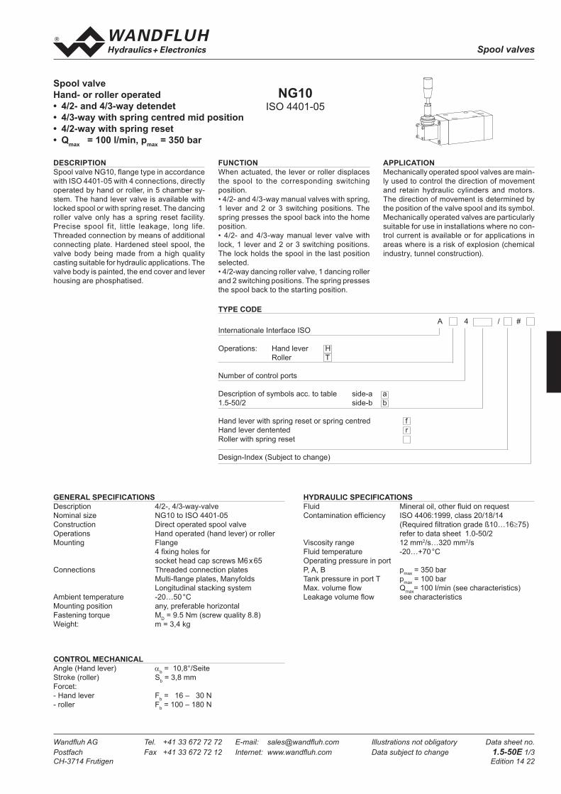
Spool valves
Wandfl uh AG Tel. +41 33 672 72 72 E-mail: sales@wandfl uh.com Illustrations not obligatory Data sheet no.
Postfach Fax +41 33 672 72 12 Internet: www.wandfl uh.com Data subject to change 1.5-50E 1/3
CH-3714 Frutigen Edition 14 22
FUNCTION
When actuated, the lever or roller displaces
the spool to the corresponding switching
position.
• 4/2- and 4/3-way manual valves with spring,
1 lever and 2 or 3 switching positions. The
spring presses the spool back into the home
position.
• 4/2- and 4/3-way manual lever valve with
lock, 1 lever and 2 or 3 switching positions.
The lock holds the spool in the last position
selected.
• 4/2-way dancing roller valve, 1 dancing roller
and 2 switching positions. The spring presses
the spool back to the starting position.
Spool valve
Hand- or roller operated
• 4/2- and 4/3-way detendet
• 4/3-way with spring centred mid position
• 4/2-way with spring reset
• Qmax
= 100 l/min, pmax
= 350 bar
TYPE CODE
CONTROL MECHANICAL
Angle (Hand lever) αb = 10,8°/Seite
Stroke (roller) Sb = 3,8 mm
Forcet:
- Hand lever Fb = 16 – 30 N
- roller Fb = 100 – 180 N
GENERAL SPECIFICATIONS
Description 4/2-, 4/3-way-valve
Nominal size NG10 to ISO 4401-05
Construction Direct operated spool valve
Operations Hand operated (hand lever) or roller
Mounting Flange
4 fi xing holes for
socket head cap screws M6 x 65
Connections Threaded connection plates
Multi-fl ange plates, Manyfolds
Longitudinal stacking system
Ambient temperature -20…50 °C
Mounting position any, preferable horizontal
Fastening torque MD = 9.5 Nm (screw quality 8.8)
Weight: m = 3,4 kg
HYDRAULIC SPECIFICATIONS
Fluid Mineral oil, other fl uid on request
Contamination effi ciency ISO 4406:1999, class 20/18/14
(Required fi ltration grade ß10…16≥75)
refer to data sheet 1.0-50/2
Viscosity range 12 mm2/s…320 mm2/s
Fluid temperature -20…+70 °C
Operating pressure in port
P, A, B pmax
= 350 bar
Tank pressure in port T pmax
= 100 bar
Max. volume fl ow Qmax
= 100 l/min (see characteristics)
Leakage volume fl ow see characteristics
APPLICATION
Mechanically operated spool valves are main-
ly used to control the direction of movement
and retain hydraulic cylinders and motors.
The direction of movement is determined by
the position of the valve spool and its symbol.
Mechanically operated valves are particularly
suitable for use in installations where no con-
trol current is available or for applications in
areas where is a risk of explosion (chemical
industry, tunnel construction).
DESCRIPTION
Spool valve NG10, fl ange type in accordance
with ISO 4401-05 with 4 connections, directly
operated by hand or roller, in 5 chamber sy-
stem. The hand lever valve is available with
locked spool or with spring reset. The dancing
roller valve only has a spring reset facility.
Precise spool fit, little leakage, long life.
Threaded connection by means of additional
connecting plate. Hardened steel spool, the
valve body being made from a high quality
casting suitable for hydraulic applications. The
valve body is painted, the end cover and lever
housing are phosphatised.
NG10ISO 4401-05
A 4 / #
Internationale Interface ISO
Operations: Hand lever H
Roller T
Number of control ports
Description of symbols acc. to table side-a a
1.5-50/2 side-b b
Hand lever with spring reset or spring centred f
Hand lever dentented r
Roller with spring reset
Design-Index (Subject to change)

Spool valves
Wandfl uh AG Tel. +41 33 672 72 72 E-mail: sales@wandfl uh.com Illustrations not obligatory Data sheet no.
Postfach Fax +41 33 672 72 12 Internet: www.wandfl uh.com Data subject to change 1.5-50E 2/3
CH-3714 Frutigen Edition 14 22
Volume fl ow direction
P - A P - B P - T A - T B - T
Z100/J100 2 2 - 2 2
D101/Z101 2 2 - 2 2
D102/Z102 2 2 - 1 1
D103/Z103 2 2 3 2 2
D104/Z104 1 1 - 1 1
D105/Z105 1 1 - 2 2
Pressure drop
curve no.Symbol
TYPE LIST / DESIGNATION OF SYMBOLS
CHARACTERSISTICS Oilviscosity υ = 30 mm2/s
p = f (Q) Performance limits QL = f (p) Leakage volume fl ow characteristics
per control edge
∆p = f (Q) Pressure drop volume fl ow characteristics
p [bar]K0427
Q [l/min]
Z101/D101
Z102/D102Z105/D105
050
100150200250300350
0 20 40 60 80 100
Z100Z103/D103
Z104/D104
00
K0303
Q [l/min]
5
10
15
20
20 40 60 80 100
p [bar]
1
2
3
p [bar]
K 03 0 4
Q [cm /min]3
0 50 100 150 200 250 300 3500
50
100
150
200
250
300
a b
BA
P T
a b
BA
P T
o
a b
BA
P T
o
a b
BA
P T
o
a b
BA
P T
o
a b
BA
P T
ab
BA
P T
a b
BA
P T
ab
BA
P T
ab
BA
P T
a b
BA
P T
ab
BA
P T
a b
BA
P T
ab
BA
P T
ab
BA
P T
D101a
D102a
D103a
D104a
D105a
Z101a
Z102a
Z103a
Z104a
Z105a
Z101b
Z102b
Z103b
Z104b
Z105b
o
D101b
D102b
D103b
D104b
D105b
a b
BA
P T
Z100a Z100ba b
BA
P T
4/2-way valve Transitional functions
4/3-way valve 4/2-way valve Transitional functions
(only by hand lever operation)

Spool valves
Wandfl uh AG Tel. +41 33 672 72 72 E-mail: sales@wandfl uh.com Illustrations not obligatory Data sheet no.
Postfach Fax +41 33 672 72 12 Internet: www.wandfl uh.com Data subject to change 1.5-50E 3/3
CH-3714 Frutigen Edition 14 22
Position Article Description
10 253.2000 Hand control head BH ll
20 253.4100 Mechanical control head AT ll
30 246.3125 Socket head cap screw M6 x 25 DIN 912
40 246.1140 Socket head cap screw M4 x 40 DIN 912
50 238.0201 Plug screw M8 x1 DIN 908
(by spring centred version)
239.2000 Plug screw
(by dedented version)
60 049.1080 Cop. seal ring NG 8 x11,5 x1 DIN 7603
(only by dedented version)
70 221.2271 Spring tension pin ∅ 3 x16 DIN 1481
80 160.2140 O-ring ID14,00x1,78
DIMENSIONS
Roller Hand lever
PARTS LIST
Technical explanation see data sheet 1.0-100
ACCESSORIES
Threaded connection plates, Multi-fl ange plates
and longitudinal stacking system register 2.9
20
70
6,5
10,5
22,8
93 23,843,8
168,6
60
62
7(
)55
40
10
80
30
50,60
10,5
6,5
60
62
55
7()16
2
42,8
61,8 93 23,8
178,6
16
Wide = 8
Breite = 8
Largeur = 8
T0
B
P
A
T
54
1,5
9,7
46
16,8
20,8
48

Spool valves
Wandfl uh AG Tel. +41 33 672 72 72 E-mail: sales@wandfl uh.com Illustrations not obligatory Data sheet no.
Postfach Fax +41 33 672 72 12 Internet: www.wandfl uh.com Data subject to change 1.6-15E 1/3
CH-3714 Frutigen Edition 08 06
Spool valve pneumatically operated
• 4/2-way impuls version
• 4/3-way with spring centered mid position
• 4/2-way with spring reset
• Qmax
= 8 l/min, pmax
= 350 bar
FUNCTION
When actuated, the pneumatic head displaces the valve spool to the corresponding switching position.• 4/2-way inpulse spool valve:2 pneumatic head and 2 locking switch positi-ons. When the pneumatic head is not actuated, the spool is held by the lock in the correspon-ding switching position.• 4/3-way spool valve:2 pneumatic heads and 3 switching position. When the air head is not actuated, the spool is switched back to the centre position via the springs.• 4/2-way spool valves:1 pneumatic head and 2 switching positions. When the pneumatic head is not actuated, the spool is switched back to the home position by the spring.
APPLICATION
Pneumatically operated spool valves are mainly used to control the direction of mo-vement and for retaining hydraulic cylinders and motors. The direction of movement is determinet by the position of the valve spool and its symbol. Pneumatically operated valves are particularly suitable for use in areas where there is a risk of explosion in the chemical or mining industries and also in industrial installa-tions where compressed air is used. The Mini-3 valves are intended for applications where both the dimensions and weight should be reduced as much as possible or for the pilot control of larger valves.
GENERAL SPECIFICATIONS
Description 4/2-, 4/3-way valveNominal size NG3-Mini to Wandfl uh standardConstruction Direct operated spool valveOperations PneumaticallyMounting Flange 3 fi xing holes for socket head cap screws M4x30Connections Threaded connection plates Multi-fl ange plates, Manyfolds Longitudinal stacking systemAmbient temperature -20…50°CMounting position any, preferably horizontalFastening torque M
D= 2,8 Nm (screw quality 8.8)
Weight: 4/2-way Impuls m = 0,57 kg4/3-way m = 0,57 kg4/2-way (1 control head) m = 0,42 kg
HYDRAULIC SPECIFICATIONS
Fluid Mineral oil, other fl uid on requestContamination effi ciency ISO 4406:1999, class 20/18/14 (Required fi ltration grade ß10…16≥75) refer to data sheet 1.0-50/2Viscosity range 12 mm2/s…320 mm2/sFluid temperature -20…+70°COperating pressure inPort P, A, B p
max = 350 bar (p
T < 20 bar)
pmax
= 315 bar (pT > 20 bar)
Tank pressure intank T p
Tmax = 100 bar
Max. volume fl ow Qmax
= 8 l/min, see characteristicsLeakage volume fl ow see characteristics
CONTROL PNEUMATIC operated with control head CK IIIMin. pilot pressure p
st,
min = 2 bar by p
T = 20 bar
pst,
min = 5 bar by p
T = 100 bar
Control volume Vst = 2 cm3
TYPE CODE
W D L F A03 - #
Spool valve direct operated
Pneumatically
Flange construction
Mounting interface NG3-Mini
Symbols accord. to table on page 1.6-15/2
Design-Index (Subject to change)
DESCRIPTION
Spool valve NG3-Mini, flange type in acc-ordance to Wandfl uh standard with 4 connec-tions. Directly and pneumatically operated spool valve in a 5 chamber system. Spool blocked or with spring reset. Spool type pneu-matic head, precise spool fi t, small leakage, long life. Threaded connection by means of additional connecting plate. Spool made from hardened steel, the valve body is made from a high quality casting suitable for hydraulic applications. The valve bodies are painted. The end covers ant the pneumatic heads are zinc coated.
CONTENTS
GENERAL SPECIFICATIONS ......................1
HYDRAULIC SPECIFICATIONS ..................1
CONTROL PNEUMATIC ..............................1
TYPE CHARTS / SYMBOLS ........................2
CHARACTERISTICS ....................................2
DIMENSIONS ...............................................3
PARTS LIST .................................................3
ACCESSORIES............................................3
NG3-Mini®

Spool valves
Wandfl uh AG Tel. +41 33 672 72 72 E-mail: sales@wandfl uh.com Illustrations not obligatory Data sheet no.
Postfach Fax +41 33 672 72 12 Internet: www.wandfl uh.com Data subject to change 1.6-15E 2/3
CH-3714 Frutigen Edition 08 06
Leakage envelope AB1/ACB/ADB/AFB/AGB
Leakage envelope BEA
a b
BA
P T
a b
BA
P T
o
a b
BA
P T
o
a b
BA
P T
o
a b
BA
P T
o
a b
BA
P T
a b
BA
P T
ab
BA
P T
a b
BA
P T
ab
BA
P T
ab
BA
P T
a b
BA
P T
a b
BA
P T
ab
BA
P T
a b
BA
P T
ab
BA
P T
ab
BA
P T
A B 3
A C B
A D B
B E A
A F B
A G B
A B 1
A C 1
A D 1
B E 1
A F 1
A G 1
A B 2
C B 2
D B 2
E A 2
F B 2
G B 2
a b
BA
P T
o
Volume fl ow direction
P - A P - B P - T A - T B - T
AB1/AB2/AB3 4 4 - 3 3
ACB/AC1/CB2 4 4 - 2 2
ADB/AD1/DB2 3 3 - 2 2
BEA/BE1/EA2 6 6 4 5 5
AFB/AF1/FB2 2 2 1 2 2
AGB/AG1/GB2 3 3 - 3 3
Pressure drop
Curve no.Symbol
TYPE LIST / DESIGNATION OF SYMBOLS
4/3-way valve spring centered
4/2-way valve impulse 4/2-way valve with spring reset Transitional functions operation A-side operation B-side
CHARACTERSISTICS Ölviscosity υ = 30 mm2/sp = f (Q) Performance limits Q
L = f (p) Leakage volume fl ow characteristics
per control edge
∆p = f (Q) Pressure drop volume fl ow characteristics
K0655 K0263
080
K0528
Q [l/min]2 4 6 71 3 5
4
8
12
16
p [bar]
6
5
4
321
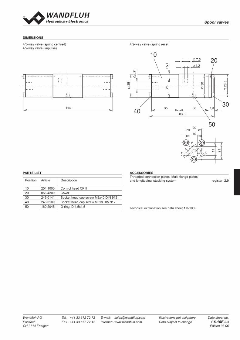
Spool valves
Wandfl uh AG Tel. +41 33 672 72 72 E-mail: sales@wandfl uh.com Illustrations not obligatory Data sheet no.
Postfach Fax +41 33 672 72 12 Internet: www.wandfl uh.com Data subject to change 1.6-15E 3/3
CH-3714 Frutigen Edition 08 06
PARTS LIST
Position Article Description
10 254.1000 Control head CKIII
20 056.4200 Cover
30 246.0141 Socket head cap screw M3x40 DIN 912
40 246.0109 Socket head cap screw M3x8 DIN 912
50 160.2045 O-ring ID 4,5x1,5
DIMENSIONS
4/3-way valve (spring centred)4/2-way valve (impulse)
4/2-way valve (spring reset)
Technical explanation see data sheet 1.0-100E
ACCESSORIES
Threaded connection plates, Multi-fl ange platesand longitudinal stacking system register 2.9
1 1 4
A
T
P
B
T0
2 0
1 0
11
21
2 0
3 0
5 0
4 0
1 0
3 5 3 8
8 3 , 3
29
25
5(
)
4 , 2
7 , 5
30
7 , 3
G1/8"
28,5

Spool valves
Wandfl uh AG Tel. +41 33 672 72 72 E-mail: sales@wandfl uh.com Illustrations not obligatory Data sheet no.
Postfach Fax +41 33 672 72 12 Internet: www.wandfl uh.com Data subject to change 1.6-20E 1/3
CH-3714 Frutigen Edition 06 20
GENERAL SPECIFICATIONS
Description 4/2-, 4/3-way valve
Nominal size NG4-Mini to Wandfl uh standard
Constructions Direct operated spool valve
Operations Pneumatically
Mounting Flange
3 fi xing holes for
socket head cap screws M5 x 40
Connections Threaded connection plates
Multi-fl ange plates
Longitudinal stacking system
Ambient temperature -20…50 °C
Mountin position any, preferably horizontal
Fastening torque MD= 5,5 Nm (screw quality 8.8)
Weight:
4/2-way Impuls m = 1,04 kg
4/3-way m = 1,04 kg
4/2-way (1 control head) m = 0,84 kg
Spool valve pneumatically operated
• 4/2-way impuls version detended
• 4/3-way with spring centered mid position
• 4/2-way with spring reset
• Qmax
= 20 l/min, pmax
= 315 bar
HYDRAULIC SPECIFICATIONS
Fluid Mineral oil, other fl uid on request
Contamination effi ciency ISO 4406:1999, class 20/18/14
(Required fi ltration grade ß10…16≥75)
refer to data sheet 1.0-50/2
Viscosity range 12 mm2/s…320 mm2/s
Fluid temperature -20…+70 °C
Operating pressure
in port P, A, B pmax
= 315 bar
Tank pressure
in port T pmax
= 100 bar
Max. Volume fl ow Qmax
= 20 l/min, see characteristics
Leakage volume fl ow see characteristics
CONTROL PNEUMATIC operated with control head
Min. pilot pressure pst,
min = 2,5 bar at p
T = 20 bar
pst,
min = 5 bar at p
T = 100 bar
Control volume Vst = 2,5 cm3
CONTENT
GENERAL SPECIFICATIONS ......................1
HYDRAULIC SPECIFICATIONS ..................1
CONTROL PNEUMATIC ..............................1
TYPE CHARTS / SYMBOLS .........................2
CHARACTERISTICS ....................................2
DIMENSIONS ...............................................3
PARTS LIST .................................................3
ACCESSORIES............................................3
FUNCTION
When actuated, the pneumatic head displaces
the valve spool to the corresponding switching
position.
• 4/2-way inpulse spool valve:
2 pneumatic head and 2 locking switch positi-
ons. When the pneumatic head is not actuated,
the spool is held by the lock in the correspon-
ding switching position.
• 4/3-way spool valve:
2 pneumatic heads and 3 switching position.
When the air head is not actuated, the spool
is switched back to the centre position via the
springs.
• 4/2-way spool valves:
1 pneumatic head and 2 switching positions.
When the pneumatic head is not actuated, the
spool is switched back to the home position
by the spring.
APPLICATION
Pneumatically operated spool valves are
mainly used to control the direction of move-
ment and for retaining hydraulic cylinders and
motors. The direction of movement is deter-
minet by the position of the valve spool and
its symbol. Pneumatically operated valves are
particularly suitable for use in areas where
there is a risk of explosion in the chemical or
mining industries and also in industrial instal-
lations where compressed air is used. The
Mini-4 valves are intended for applications
where both the dimensions and weight should
be reduced as much as possible or for the pilot
control of larger valves.
DESCRIPTION
Spool valve NG4-Mini, fl ange type in accord-
ance to Wandfl uh standard with 4 connections.
Directly and pneumatically operated spool
valve in a 5 chamber system. Spool blocked
or with spring reset. Spool type pneumatic
head, precise spool fi t, small leakage, long life.
Threaded connection by means of additional
connecting plate. Spool made from hardened
steel, the valve body is made from a high qua-
lity casting suitable for hydraulic applications.
The valve bodies are painted. The end covers
and the pneumatic heads are zinc coated.
TYPE CODE
B K 4 #
Interface
Operation pneumatically
No. of control ports
Type charts / Symbols acc. to table 1.6-20/2
Design-Index (Subject to change)
NG4-Mini®

Spool valves
Wandfl uh AG Tel. +41 33 672 72 72 E-mail: sales@wandfl uh.com Illustrations not obligatory Data sheet no.
Postfach Fax +41 33 672 72 12 Internet: www.wandfl uh.com Data subject to change 1.6-20E 2/3
CH-3714 Frutigen Edition 06 20
(1) pV = 2,5 bar; p
T = 20 bar
(2) pV = 5 bar; p
T = 160 bar
a b
BA
P T
a b
BA
P T
o
a b
BA
P T
o
a b
BA
P T
o
a b
BA
P T
o
a b
BA
P T
a b
BA
P T
ab
BA
P T
a b
BA
P T
ab
BA
P T
ab
BA
P T
a b
BA
P T
a b
BA
P T
ab
BA
P T
a b
BA
P T
ab
BA
P T
ab
BA
P T
J 4 0
D 4 1
D 4 2
D 4 3
D 4 4
D 4 5
Z 4 0 a
Z 4 1 a
Z 4 2 a
Z 4 3 a
Z 4 4 a
Z 4 5 a
Z 4 0 b
Z 4 1 b
Z 4 2 b
Z 4 3 b
Z 4 4 b
Z 4 5 b
a b
BA
P T
o
Volume fl ow direction
P - A P - B P - T A - T B - T
Z40/J40 5 5 - 2 2
D41/Z41 5 5 - 2 2
D42/Z42 5 5 - 1 1
D43/Z43 4 4 6 2 2
D44/Z44 4 4 3 2 2
D45/Z45 4 4 - 2 2
Pressure drop
Curve no.Symbol
TYPE LIST / DESIGNATION OF SYMBOLS
4/3-way valve spring centered
4/2-way valve impulse 4/2-way valve with spring reset Transitional functions
operation A-side operation B-side
CHARACTERSISTICS Oilviscosity υ = 30 mm2/s
p = f (Q) Performance limits QL = f (p) Leakage volume fl ow characteristics
per control edge
∆p = f (Q) Pressure drop volume fl ow characteristics
00
p [bar]K0101
Q [l/min]5 1510 20
5
10
15
20
25
306
5
4
3
2
1
K0100
Z40 (1+2)
J40 (1)
J40 (2)
Z44/D44 (1)
Z43/D43 (1)
Z41/D41 (1+2)Z42/D42 (1+2)Z43/D43 (2)
Z44/D44 (2)Z45/D45 (1+2)
0
p [bar]
50100150200250300350
50 10 15 20 Q [l/min]
0 50 100 150 200 250 300 350
Q [cm3/min]K0126

Spool valves
Wandfl uh AG Tel. +41 33 672 72 72 E-mail: sales@wandfl uh.com Illustrations not obligatory Data sheet no.
Postfach Fax +41 33 672 72 12 Internet: www.wandfl uh.com Data subject to change 1.6-20E 3/3
CH-3714 Frutigen Edition 06 20
Position Article Description
10 254.2000 Control head BKII
20 057.4202 Cover
30 246.1113 Socket head cap screw M4 x12 DIN 912
40 246.1146 Socket head cap screw M4 x45 DIN 912
50 160.2052 O-ring ID 5,28 x1,78
1 4 1
T
A
P
B
T0
2 8
1 4
27
14
5 0
1 02 0
3 0
4 0
9 , 5
5 , 5
38
1 05 43 8
1 0 7 , 5
32
6(
)
35
G 1 / 8 "
35
PARTS LIST
DIMENSIONS
4/3-way valve (spring centred)
4/2-way valve (impulse)
4/2-way valve (spring reset)
Technical explanation see data sheet 1.0-100
ACCESSORIES
Threaded connection plates, Multi-fl ange plates
and longitudinal stacking system register 2.9

Spool valves
Wandfl uh AG Tel. +41 33 672 72 72 E-mail: sales@wandfl uh.com Illustrations not obligatory Data sheet no.
Postfach Fax +41 33 672 72 12 Internet: www.wandfl uh.com Data subject to change 1.6-30E 1/3
CH-3714 Frutigen Edition 06 20
GENERAL SPECIFICATIONS
Description 4/2-, 4/3-way valve
Nominal size NG6 to ISO 4401-03
Constructions Direct operated spool valve
Operations Pneumatically
Mounting Flange
4 fi xing holes for
socket head cap screws M5 x 45
Connections Threaded connection plates
Multi-fl ange plates
Longitudinal stacking system
Ambient temperature -20…50 °C
Mountin position any, preferably horizontal
Fastening torque MD= 5,5 Nm (screw quality 8.8)
Weight:
4/2-way impuls m = 2,0 kg
4/3-way m = 2,0 kg
4/2-way (1 control head) m = 1,6 kg
Spool valve pneumatically operated
• 4/2-way impuls version detended
• 4/3-way with spring centered mid position
• 4/2-way with spring reset
• Qmax
= 60 l/min, pmax
= 350 bar
HYDRAULIC SPECIFICATIONS
Fluid Mineral oil, other fl uid on request
Contamination effi ciency ISO 4406:1999, class 20/18/14
(Required fi ltration grade ß10…16≥75)
refer to data sheet 1.0-50/2
Viscosity range 12 mm2/s…320 mm2/s
Fluid temperature -20…+70 °C
Operating pressure
in port P, A, B pmax
= 350 bar
Tank pressure
in port T pmax
= 200 bar
Max. Volume fl ow Qmax
= 60 l/min, see characteristics
Leakage volume fl ow see characteristics
CONTROL PNEUMATIC operated with control head
Min. pilot pressure pst,
min = 1,5 bar at p
T = 20 bar
pst,
min = 5 bar at p
T = 200 bar
Control volume Vst = 6,9 cm3
CONTENT
GENERAL SPECIFICATIONS ......................1
HYDRAULIC SPECIFICATIONS ..................1
CONTROL PNEUMATIC ..............................1
TYPE CHARTS / SYMBOLS .........................2
CHARACTERISTICS ....................................2
DIMENSIONS ...............................................3
PARTS LIST .................................................3
ACCESSORIES............................................3
FUNCTION
When actuated, the pneumatic head displaces
the valve spool to the corresponding switching
position.
• 4/2-way inpulse spool valve:
2 pneumatic head and 2 locking switch positi-
ons. When the pneumatic head is not actuated,
the spool is held by the lock in the correspon-
ding switching position.
• 4/3-way spool valve:
2 pneumatic heads and 3 switching position.
When the air head is not actuated, the spool
is switched back to the centre position via the
springs.
• 4/2-way spool valves:
1 pneumatic head and 2 switching positions.
When the pneumatic head is not actuated, the
spool is switched back to the home position
by the spring.
APPLICATION
Pneumatically operated spool valves are
mainly used to control the direction of mo-
vement and for retaining hydraulic cylinders
and motors. The direction of movement is
determinet by the position of the valve spool
and its symbol. Pneumatically operated valves
are particularly suitable for use in areas where
there is a risk of explosion in the chemical or
mining industries and also in industrial instal-
lations where compressed air is used.
DESCRIPTION
Spool valve NG6, fl ange type in accordance to
ISO 4401-03 standard with 4 connections. Di-
rectly and pneumatically operated spool valve
in a 5 chamber system. Spool blocked or with
spring reset. Spool type pneumatic head, pre-
cise spool fi t, small leakage, long life. Threaded
connection by means of additional connecting
plate. Spool made from hardened steel, the
valve body is made from a high quality casting
suitable for hydraulic applications. The valve
bodies are painted. The end covers and the
pneumatic heads are zinc coated.
TYPE CODE
A K 4 #
International interface ISO
Operation pneumatically
No. of control ports
Type charts/Symbols acc. to table 1.6-30/2
Design-Index (Subject to change)
NG6ISO 4401-03
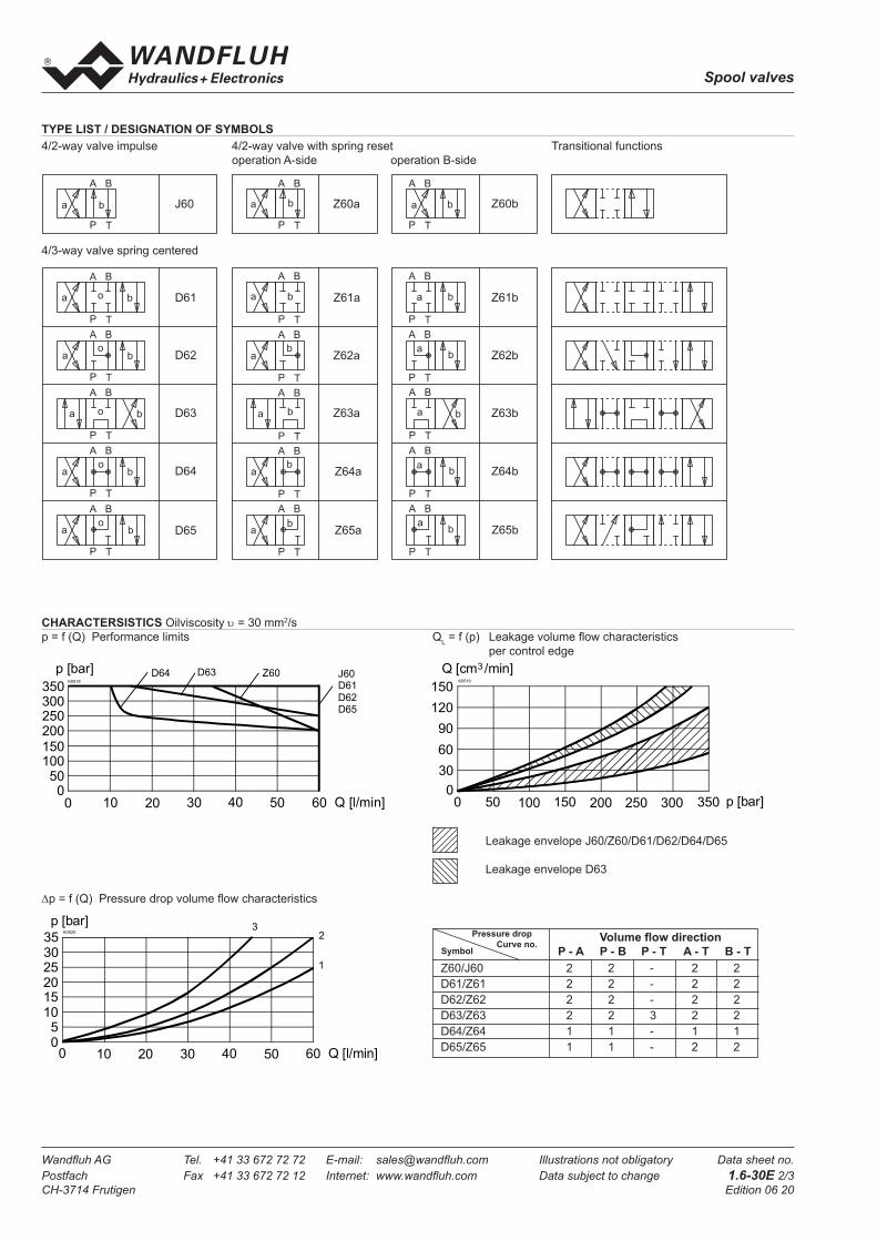
Spool valves
Wandfl uh AG Tel. +41 33 672 72 72 E-mail: sales@wandfl uh.com Illustrations not obligatory Data sheet no.
Postfach Fax +41 33 672 72 12 Internet: www.wandfl uh.com Data subject to change 1.6-30E 2/3
CH-3714 Frutigen Edition 06 20
Leakage envelope J60/Z60/D61/D62/D64/D65
Leakage envelope D63
a b
BA
P T
a b
BA
P T
o
a b
BA
P T
o
a b
BA
P T
o
a b
BA
P T
o
a b
BA
P T
a b
BA
P T
ab
BA
P T
a b
BA
P T
ab
BA
P T
ab
BA
P T
a b
BA
P T
a b
BA
P T
ab
BA
P T
a b
BA
P T
ab
BA
P T
ab
BA
P T
J 6 0
D 6 1
D 6 2
D 6 3
D 6 4
D 6 5
Z 6 0 a
Z 6 1 a
Z 6 2 a
Z 6 3 a
Z 6 4 a
Z 6 5 a
Z 6 0 b
Z 6 1 b
Z 6 2 b
Z 6 3 b
Z 6 4 b
Z 6 5 b
a b
BA
P T
o
Volume fl ow direction
P - A P - B P - T A - T B - T
Z60/J60 2 2 - 2 2
D61/Z61 2 2 - 2 2
D62/Z62 2 2 - 2 2
D63/Z63 2 2 3 2 2
D64/Z64 1 1 - 1 1
D65/Z65 1 1 - 2 2
Pressure drop
Curve no.Symbol
TYPE LIST / DESIGNATION OF SYMBOLS
4/3-way valve spring centered
4/2-way valve impulse 4/2-way valve with spring reset Transitional functions
operation A-side operation B-side
CHARACTERSISTICS Oilviscosity υ = 30 mm2/s
p = f (Q) Performance limits QL = f (p) Leakage volume fl ow characteristics
per control edge
∆p = f (Q) Pressure drop volume fl ow characteristics
0
K0518
Q [l/min]
p [bar]
50100150
200250300350
Z60D63D64
0 10 20 30 40 50
J60D61
D62D65
60
p [bar]K0520
Q [l/min]
1
2
05
101520253035
0 10 20 30 40 50 60
3
p [bar]
K0519
Q [cm /min]3
0 50 100 150 200 250 300 3500
30
60
90
120
150
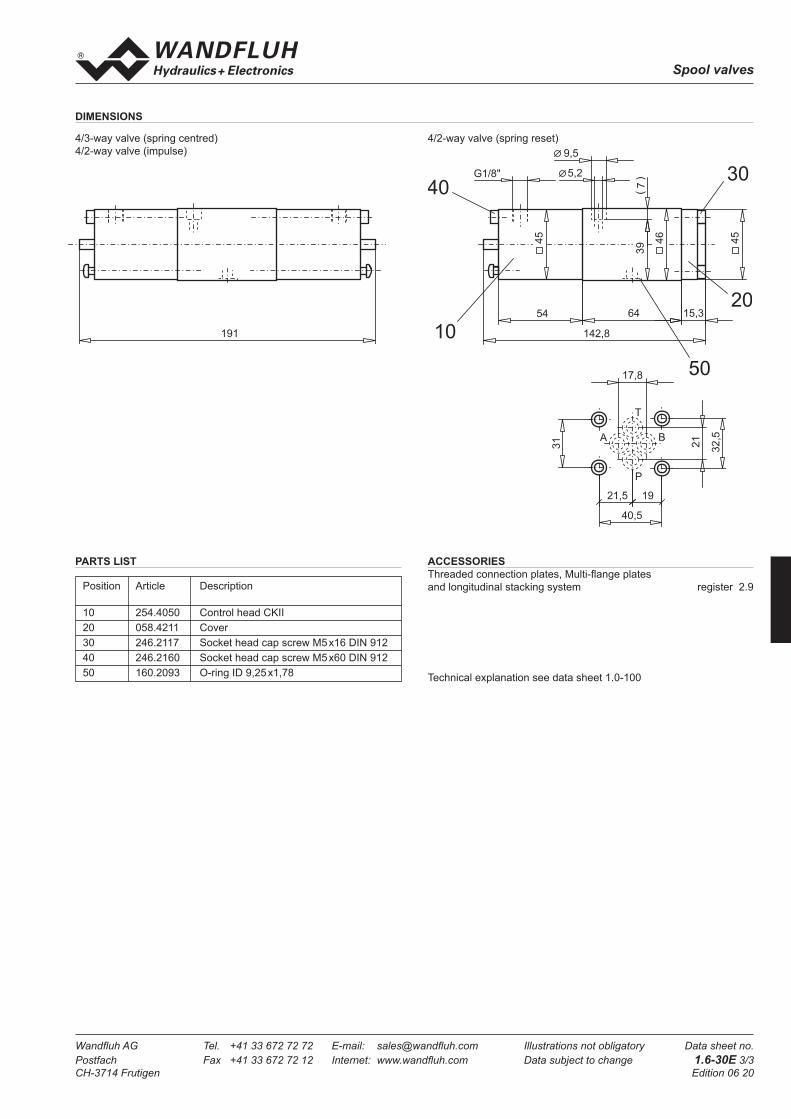
Spool valves
Wandfl uh AG Tel. +41 33 672 72 72 E-mail: sales@wandfl uh.com Illustrations not obligatory Data sheet no.
Postfach Fax +41 33 672 72 12 Internet: www.wandfl uh.com Data subject to change 1.6-30E 3/3
CH-3714 Frutigen Edition 06 20
PARTS LIST
Position Article Description
10 254.4050 Control head CKII
20 058.4211 Cover
30 246.2117 Socket head cap screw M5 x16 DIN 912
40 246.2160 Socket head cap screw M5 x60 DIN 912
50 160.2093 O-ring ID 9,25 x1,78
1 0
2 0
3 04 0
5 0
5 4 6 4 1 5 , 3
1 4 2 , 8
45
45
46
39
7(
)5 , 2
9 , 5
G 1 / 8 "
1 9 1
A
T
B
P
1 7 , 8
2 1 , 5 1 9
4 0 , 5
31
32,5
21
DIMENSIONS
4/3-way valve (spring centred)
4/2-way valve (impulse)
4/2-way valve (spring reset)
Technical explanation see data sheet 1.0-100
ACCESSORIES
Threaded connection plates, Multi-fl ange plates
and longitudinal stacking system register 2.9

Spool valves
Wandfl uh AG Tel. +41 33 672 72 72 E-mail: sales@wandfl uh.com Illustrations not obligatory Data sheet no.
Postfach Fax +41 33 672 72 12 Internet: www.wandfl uh.com Data subject to change 1.6-40E 1/3
CH-3714 Frutigen Edition 08 48
CONTENT
GENERAL SPECIFICATIONS ......................1
HYDRAULIC SPECIFICATIONS ..................1
CONTROL PNEUMATIC ..............................1
TYPE CHARTS / SYMBOLS .........................2
CHARACTERISTICS ....................................2
DIMENSIONS ...............................................3
PARTS LIST .................................................3
ACCESSORIES............................................3
TYPE CODE
Spool valve pneumatically operated
• 4/2-way impuls version detended
• 4/3-way with spring centered mid position
• 4/2-way with spring reset
• Qmax
= 80 l/min, pmax
= 350 bar
A K 4 #
International interface ISO
Operation pneumatically
No. of control ports
Type charts/Symbols acc. to table 1.6-40/2
Design-Index (Subject to change)
DESCRIPTION
Spool valve NG10, fl ange type in accordance
to ISO 4401-05 standard with 4 connections.
Directly and pneumatically operated spool
valve in a 5 chamber system. Spool blocked
or with spring reset. Spool type pneumatic
head, precise spool fi t, small leakage, long life.
Threaded connection by means of additional
connecting plate. Spool made from hardened
steel, the valve body is made from a high qua-
lity casting suitable for hydraulic applications.
The valve bodies are painted. The end covers
and the pneumatic heads are zinc coated.
FUNCTION
When actuated, the pneumatic head displaces
the valve spool to the corresponding switching
position.
• 4/2-way inpulse spool valve:
2 pneumatic head and 2 locking switch positi-
ons. When the pneumatic head is not actuated,
the spool is held by the lock in the correspon-
ding switching position.
• 4/3-way spool valve:
2 pneumatic heads and 3 switching position.
When the air head is not actuated, the spool
is switched back to the centre position via the
springs.
• 4/2-way spool valves:
1 pneumatic head and 2 switching positions.
When the pneumatic head is not actuated, the
spool is switched back to the home position
by the spring.
APPLICATION
Pneumatically operated spool valves are mainly
used to control the direction of movement and
for retaining hydraulic cylinders and motors.
The direction of movement is determinet by
the position of the valve spool and its symbol.
Pneumatically operated valves are particularly
suitable for use in areas where there is a risk of
explosion in the chemical or mining industries
and also in industrial installations where com-
pressed air is used.
GENERAL SPECIFICATIONS
Description 4/2-, 4/3-way valve
Nominal size NG10 to ISO 4401-05
Constructions Direct operated spool valve
Operations Pneumatically
Mounting Flange
4 fi xing holes for
socket head cap screws M6x65
Connections Threaded connection plates
Multi-fl ange plates
Longitudinal stacking system
Ambient temperature -20…50 °C
Mountin position any, preferably horizontal
Fastening torque MD= 9,5 Nm (screw quality 8.8)
Weight:
4/2-way Impuls m = 4,8 kg
4/3-way m = 4,8 kg
4/2-way (1 control head) m = 3,8 kg
HYDRAULIC SPECIFICATIONS
Fluid Mineral oil, other fl uid on request
Contamination effi ciency ISO 4406:1999, class 20/18/14
(Required fi ltration grade ß10...16≥75)
refer to data sheet 1.0-50/2
Viscosity range 12 mm2/s…320 mm2/s
Fluid temperature -20…+70 °C
Operating pressure
in port P, A, B pmax
= 350 bar
Tank pressure
in port T pmax
= 200 bar
Max. Volume fl ow Qmax
= 80 l/min, see characteristics
Leakage volume fl ow see characteristics
CONTROL PNEUMATIC operated with control head
Min. pilot pressure pst,
min = 2,5 bar at p
T = 20 bar
pst,
min = 5 bar at p
T = 200 bar
Control volume Vst = 10,7 cm3
NG10ISO 4401-05

Spool valves
Wandfl uh AG Tel. +41 33 672 72 72 E-mail: sales@wandfl uh.com Illustrations not obligatory Data sheet no.
Postfach Fax +41 33 672 72 12 Internet: www.wandfl uh.com Data subject to change 1.6-40E 2/3
CH-3714 Frutigen Edition 08 48
a b
BA
P T
a b
BA
P T
o
a b
BA
P T
o
a b
BA
P T
o
a b
BA
P T
o
a b
BA
P T
a b
BA
P T
ab
BA
P T
a b
BA
P T
ab
BA
P T
ab
BA
P T
a b
BA
P T
a b
BA
P T
ab
BA
P T
a b
BA
P T
ab
BA
P T
ab
BA
P T
J 1 0 0
D 1 0 1
D 1 0 2
D 1 0 3
D 1 0 4
D 1 0 5
Z 1 0 0 a
Z 1 0 1 a
Z 1 0 2 a
Z 1 0 3 a
Z 1 0 4 a
Z 1 0 5 a
Z 1 0 0 b
Z 1 0 1 b
Z 1 0 2 b
Z 1 0 3 b
Z 1 0 4 b
Z 1 0 5 b
a b
BA
P T
o
Volume fl ow direction
P - A P - B P - T A - T B - T
Z100/J100 2 2 - 2 2
D101/Z101 2 2 - 2 2
D102/Z102 2 2 - 1 1
D103/Z103 2 2 3 2 2
D104/Z104 1 1 - 1 1
D105/Z105 1 1 - 2 2
Pressure drop
Curve no.Symbol
TYPE LIST / DESIGNATION OF SYMBOLS
4/3-way valve spring centered
4/2-way valve impulse 4/2-way valve with spring reset Transitional functions
operation A-side operation B-side
CHARACTERSISTICS Oilviscosity υ = 30 mm2/s
p = f (Q) Performance limits QL = f (p) Leakage volume fl ow characteristics
per control edge
∆p = f (Q) Pressure drop volume fl ow characteristics
00
K0414
Q [l/min]
5
10
15
20
20 40 60 80
1
2
3
p [bar]
p [bar]
K 03 0 4
Q [cm /min]3
0 50 100 150 200 250 300 3500
50
100
150
200
250
300
0800
K0413
Q [l/min]20 40 60 7010 30 50
p [bar]
50100150200250300350
J100
D101/D102/D104/D105Z100/D103
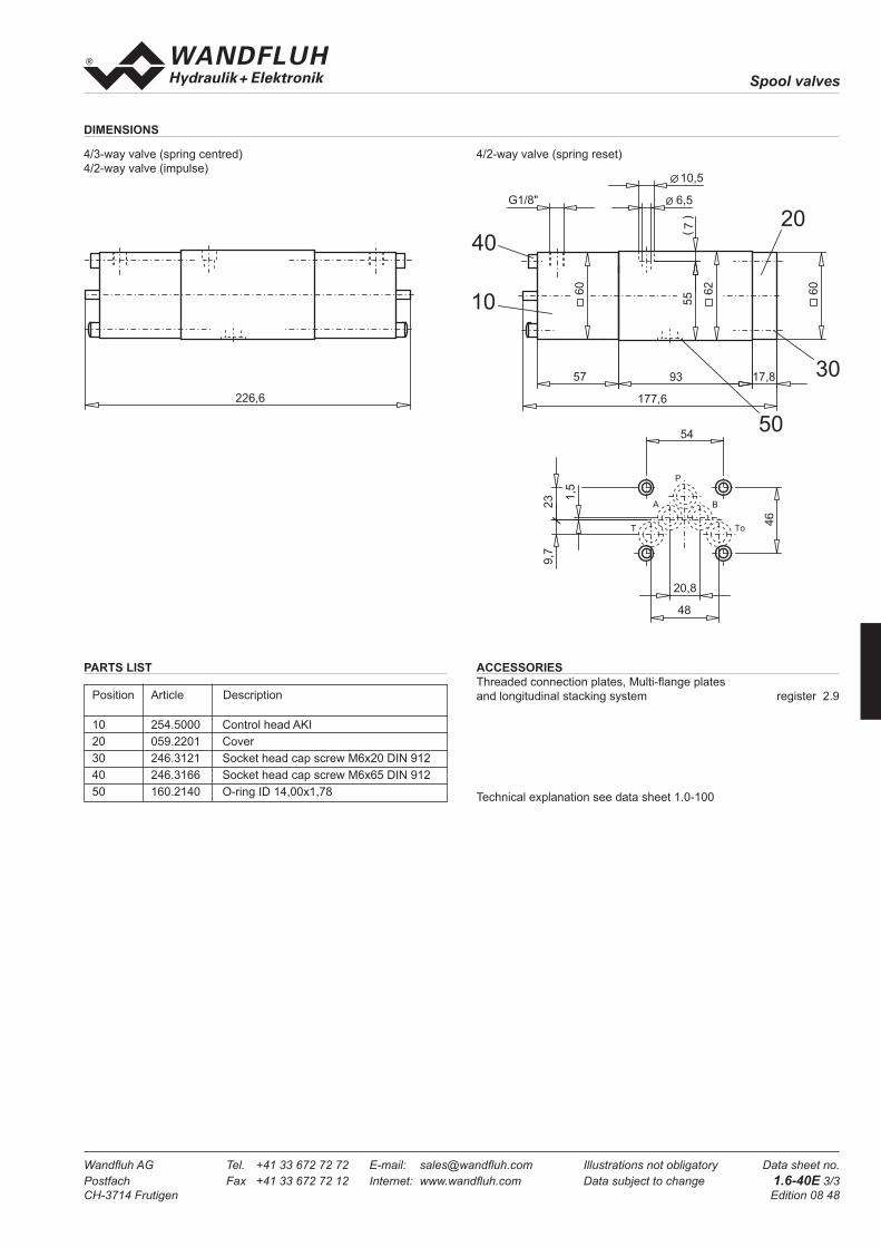
Spool valves
Wandfl uh AG Tel. +41 33 672 72 72 E-mail: sales@wandfl uh.com Illustrations not obligatory Data sheet no.
Postfach Fax +41 33 672 72 12 Internet: www.wandfl uh.com Data subject to change 1.6-40E 3/3
CH-3714 Frutigen Edition 08 48
PARTS LIST
Position Article Description
10 254.5000 Control head AKI
20 059.2201 Cover
30 246.3121 Socket head cap screw M6x20 DIN 912
40 246.3166 Socket head cap screw M6x65 DIN 912
50 160.2140 O-ring ID 14,00x1,78
2 2 6 , 6
1 0
2 0
3 0
4 0
5 0
1 7 7 , 6
1 7 , 89 35 7
55 62
60
60
1 0 , 5
6 , 5
7(
)
G 1 / 8 "
T o
A
T
P
B
5 4
2 0 , 8
4 8
1,5
9,7
23
46
DIMENSIONS
4/3-way valve (spring centred)
4/2-way valve (impulse)
4/2-way valve (spring reset)
Technical explanation see data sheet 1.0-100
ACCESSORIES
Threaded connection plates, Multi-fl ange plates
and longitudinal stacking system register 2.9

Spool valves
Wandfl uh AG Tel. +41 33 672 72 72 E-mail: sales@wandfl uh.com Illustrations not obligatory Data sheet no.
Postfach Fax +41 33 672 72 12 Internet: www.wandfl uh.com Data subject to change 1.7-15E 1/3
CH-3714 Frutigen Edition 12 47
Spool valve hydraulic operation
• 4/2-way impulse valve
• 4/3-way with spring centered mid position
• 4/2-way with spring reset
• Qmax
= 8 l/min, pmax
= 350 bar
FUNCTION
Pilot pressure shifts spool to end position.
• 4/2-way impulse
2 pilot ports. 2 detented spool positions. Spool
held in position by detent unless oposite pilot
port is pressurised to shift back.
• 4/3-way spring centered
2 pilot ports. 3 spool positions. Spool shifted
to center position by spring as pilot pressure
decays.
• 4/2-way spring offset
1 pilot port. 1 drain port on spring side, 2 spool
positions. Spool shifted to home position by
spring as pilot pressure decays.
DESCRIPTION
Spool valve NG3-Mini, fl ange type in accord-
ance to Wandfl uh standard with 4 connections.
Direct hydraulic operation via pilot ports in end
covers. 5 chamber system. Spool with spring
return or detented. Precise spool fi t, low leak,
long life. Threaded ports by means of additional
connecting plate. Hardened spool. Valve body
made of high quality casting. Valve body is
painted, the end covers are zinc coated.
APPLICATION
Hydraulically operated spool valves are mainly
used to control the direction of movement and
retain hydraulic cylinders and motors. The
direction of movement is determined by the
position of the valve spool and its symbol.
Hydraulically operated valves are particularly
suitable for use in installations where no electric
current is available or for applications in areas
with a risk of explosion (chemical industry,
tunnel construction). Mini-3 valves are used
where both, reduced dimensions and weight
are important.
CONTENTS
GENERAL SPECIFICATIONS ......................1
HYDRAULIC SPECIFICATIONS ..................1
CONTROL HYDRAULIC ..............................1
SPOOL OPTIONS/SYMBOLS ......................2
CHARACTERISTICS ....................................2
DIMENSIONS/
SECTIONAL DRAWING ...............................3
PARTS LIST .................................................3
ACCESSOIRES............................................3
GENERAL SPECIFICATIONS
Description 4/2-, 4/3-way spool valve
Nominal size NG3-Mini to Wandfl uh standard
Construction Direct operated spool valve
Operations Hydraulic
Mounting Flange
3 fi xing holes for
socket head cap screws M4x30
Connections Threaded connection plates
Multi-fl ange subplates
Longitudinal stacking system
Ambient temperature -20…+50°C
Mounting position any, preferably horizontal
Fastening torque MD= 2,8 Nm (screw quality 8.8)
Weight m = 0,4 kg
HYDRAULIC SPECIFICATIONS
Fluid Mineral oil, other fl uid on request
Contamination effi ciency ISO 4406:1999, class 20/18/14
(Required fi ltration grade ß10…16≥75)
refer to data sheet 1.0-50/2
Viscosity range 12 mm2/s…320 mm2/s
Fluid temperature -20…+70°C
Operating pressure in
ports P, A, B pmax
= 350 bar (pT < 20 bar)
pmax
= 315 bar (pT > 20 bar)
Tank pressure in
port T ptTmax
= 90 bar
resp. 10 bar below pst
Max. volume fl ow Qmax
= 8 l/min
Leakage volume fl ow see characteristics
CONTROL HYDRAULIC
Min. pilot pressure pst min
= 10 bar
Max. pilot pressure pst max
= 100 bar
Control volume Vst = 0,08 cm3
TYPE CODE
W D F F A03 - #
Spool valve direct operated
Hydraulic operation
Flange type
Interface NG3-Mini
Spool options/symbols acc. to table 1.7-15/2
Design-Index (Subject to change)
NG3-Mini®
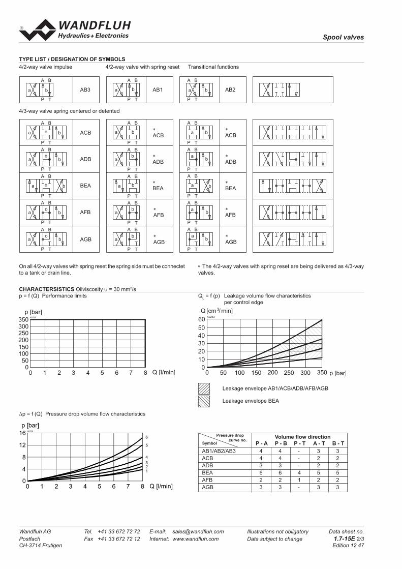
Spool valves
Wandfl uh AG Tel. +41 33 672 72 72 E-mail: sales@wandfl uh.com Illustrations not obligatory Data sheet no.
Postfach Fax +41 33 672 72 12 Internet: www.wandfl uh.com Data subject to change 1.7-15E 2/3
CH-3714 Frutigen Edition 12 47
On all 4/2-way valves with spring reset the spring side must be connectet
to a tank or drain line.
Leakage envelope AB1/ACB/ADB/AFB/AGB
Leakage envelope BEA
Volume fl ow direction
P - A P - B P - T A - T B - T
AB1/AB2/AB3 4 4 - 3 3
ACB 4 4 - 2 2
ADB 3 3 - 2 2
BEA 6 6 4 5 5
AFB 2 2 1 2 2
AGB 3 3 - 3 3
Pressure drop
curve no.Symbol
a b
BA
P T
a b
BA
P T
o
a b
BA
P T
o
a b
BA
P T
o
a b
BA
P T
o
a b
BA
P T
a b
BA
P T
ab
BA
P T
a b
BA
P T
ab
BA
P T
ab
BA
P T
a b
BA
P T
a b
BA
P T
ab
BA
P T
a b
BA
P T
ab
BA
P T
ab
BA
P T
A B 3
A C B
A D B
B E A
A F B
A G B
A B 1
*
A C B
*
A D B
*
B E A
*
A F B
*
A G B
A B 2
*
A C B
*
A D B
*
B E A
*
A F B
*
A G B
a b
BA
P T
o
∗ The 4/2-way valves with spring reset are being delivered as 4/3-way
valves.
TYPE LIST / DESIGNATION OF SYMBOLS
4/3-way valve spring centered or detented
4/2-way valve impulse 4/2-way valve with spring reset Transitional functions
CHARACTERSISTICS Oilviscosity υ = 30 mm2/s
p = f (Q) Performance limits QL = f (p) Leakage volume fl ow characteristics
per control edge
∆p = f (Q) Pressure drop volume fl ow characteristics
080
K0528
Q [l/min]2 4 6 71 3 5
4
8
12
16
p [bar]
6
5
4
321
K0263

Spool valves
Wandfl uh AG Tel. +41 33 672 72 72 E-mail: sales@wandfl uh.com Illustrations not obligatory Data sheet no.
Postfach Fax +41 33 672 72 12 Internet: www.wandfl uh.com Data subject to change 1.7-15E 3/3
CH-3714 Frutigen Edition 12 47
Position Article Description
10 056.4701 Cover
20 246.0114 Socket head cap screw M3x14 DIN 912
30 160.2045 O-ring ID 4,5x1,5
PARTS LIST
DIMENSIONS
Technical explanation see data sheet 1.0-100E
ACCESSORIES
Threaded connection plates, Multi-fl ange plates
and longitudinal stacking system register 2.9
G 1 / 8 "G 1 / 8 "
1 0
2 0
3 0
25
5(
)
2 0 , 6 3 8
7 9 , 2
2 0 , 6
29
4 , 2
7 , 5
30
T
A
P
B
T o
2 0
1 0
11
21

Spool valves
Wandfl uh AG Tel. +41 33 672 72 72 E-mail: sales@wandfl uh.com Illustrations not obligatory Data sheet no.
Postfach Fax +41 33 672 72 12 Internet: www.wandfl uh.com Data subject to change 1.7-20E 1/3
CH-3714 Frutigen Edition 12 47
Spool valve hydraulic operation
• 4/2-way impuls valve
• 4/3-way with spring centered mid position
• 4/2-way with spring reset
• Qmax
= 20 l/min, pmax
= 315 bar
FUNCTION
Pilot pressure shifts spool to end position.
• 4/2-way impulse
2 pilot ports. 2 detented spool positions. Spool
held in position by detent unless oposite pilot
port is pressurised to shift back.
• 4/3-way spring centered
2 pilot ports. 3 spool positions. Spool shifted
to center position by spring as pilot pressure
decays.
• 4/2-way spring offset
1 pilot port. 1 drain port on spring side, 2 spool
positions. Spool shifted to home position by
spring as pilot pressure decays.
DESCRIPTION
Spool valve NG4-Mini, fl ange type in accord-
ance to Wandfl uh standard with 4 connections.
Direct hydraulic operation via pilot ports in end
covers. 5 chamber system. Spool with spring
return or detented. Precise spool fi t, low leak,
long life. Threaded ports by means of additional
connecting plate. Hardened spool. Valve body
made of high quality casting. Valve body is
painted, the end covers are zinc coated.
APPLICATION
Hydraulically operated spool valves are mainly
used to control the direction of movement and
retain hydraulic cylinders and motors. The
direction of movement is determined by the
position of the valve spool and its symbol.
Hydraulically operated valves are particularly
suitable for use in installations where no electric
current is available or for applications in areas
with a risk of explosion (chemical industry,
tunnel construction). Mini-4 valves are used
where both, reduced dimensions and weight
are important.
CONTENT
GENERAL SPECIFICATIONS ......................1
HYDRAULIC SPECIFICATIONS ..................1
CONTROL HYDRAULIC ..............................1
TYPE CHARTS / SYMBOLS .........................2
CHARACTERISTICS ....................................2
DIMENSIONS ...............................................3
PARTS LIST .................................................3
ACCESSORIES............................................3
GENERAL SPECIFICATIONS
Description 4/2-, 4/3-way spool valve
Nominal size NG4-Mini to Wandfl uh standard
Construction Direct operated spool valve
Operations Hydraulic
Mounting Flange
3 fi xing holes for
socket head cap screws M5 x40
Connections Threaded connection plates
Multi-fl ange plates
Longitudinal stacking system
Ambient temperature -20…50 °C
Mounting position any, preferably horizontal
Fastening torque MD= 5,5 Nm (screw quality 8.8)
Weight m = 0,6 kg
HYDRAULIC SPECIFICATIONS
Fluid Mineral oil, other fl uid on request
Contamination effi ciency ISO 4406:1999, class 20/18/14
(Required fi ltration grade ß10…16≥75)
refer to data sheet 1.0-50/2
Viscosity range 12 mm2/s…320 mm2/s
Fluid temperature -20…+70 °C
Operating pressure
in port P, A, B pmax
= 315 bar
Tank pressure
in port T pmax
= 90 bar
resp. 10 bar below pst
Max. Volume fl ow Qmax
= 20 l/min, see characteristics
Leakage volume fl ow see characteristics
CONTROL HYDRAULIC
Min. pilot pressure pst min
= 10 bar
Max. pilot pressure pst max
= 100 bar
Control volume Vst = 0,16 cm3
TYPE CODE
B P 4 #
Interface
Hydraulic operation
No. of control ports
Type charts/Symbols acc. to table 1.7-20/2
Design-Index (Subject to change)
NG4-Mini®

Spool valves
Wandfl uh AG Tel. +41 33 672 72 72 E-mail: sales@wandfl uh.com Illustrations not obligatory Data sheet no.
Postfach Fax +41 33 672 72 12 Internet: www.wandfl uh.com Data subject to change 1.7-20E 2/3
CH-3714 Frutigen Edition 12 47
Leakage envelope J40/Z40/D41/D42/D44/D45
Leakage envelope D43
Volume fl ow direction
P - A P - B P - T A - T B - T
Z40/J40 5 5 - 2 2
D41 5 5 - 2 2
D42 5 5 - 1 1
D43 4 4 6 2 2
D44 4 4 3 2 2
D45 4 4 - 2 2
Pressure drop
curve no.Symbol
a b
BA
P T
a b
BA
P T
o
a b
BA
P T
o
a b
BA
P T
o
a b
BA
P T
o
a b
BA
P T
a b
BA
P T
ab
BA
P T
a b
BA
P T
ab
BA
P T
ab
BA
P T
a b
BA
P T
a b
BA
P T
ab
BA
P T
a b
BA
P T
ab
BA
P T
ab
BA
P T
J 4 0
D 4 1
D 4 2
D 4 3
D 4 4
D 4 5
Z 4 0 a
*
D 4 1
*
D 4 2
*
D 4 3
*
D 4 4
*
D 4 5
Z 4 0 b
*
D 4 1
*
D 4 2
*
D 4 3
*
D 4 4
*
D 4 5
a b
BA
P T
o
TYPE LIST / DESIGNATION OF SYMBOLS
4/3-way valve spring centered or detented
4/2-way valve impulse 4/2-way valve with spring reset Transitional functions
On all 4/2-way valves with spring reset the spring side must be connectet
to a tank or drain line.
∗ The 4/2-way valves with spring reset are being delivered as 4/3-way
valves.
CHARACTERSISTICS Oilviscosity υ = 30 mm2/s
p = f (Q) Performance limits QL = f (p) Leakage volume fl ow characteristics
per control edge
∆p = f (Q) Pressure drop volume fl ow characteristics
∗ Performance limit with pv = 12 bar: Q = 20 l/min and 315 bar
00
p [bar]K0097
Q [l/m in]5 1510 20
5 0
1 0 0
1 5 0
2 0 0
2 5 0
3 0 0
3 5 0
Z40
J40D43
D45
D41
D42
D44
p [bar]
K0125
0
20
40
60
80
0 50 100 150 200 250 315
Q [cm /min]3
00
p [bar]K0101
Q [l/min]5 1510 20
5
10
15
20
25
306
5
4
3
2
1

Spool valves
Wandfl uh AG Tel. +41 33 672 72 72 E-mail: sales@wandfl uh.com Illustrations not obligatory Data sheet no.
Postfach Fax +41 33 672 72 12 Internet: www.wandfl uh.com Data subject to change 1.7-20E 3/3
CH-3714 Frutigen Edition 12 47
PARTS LIST
Position Article Description
10 057.4600 Cover
20 246.1113 Socket head cap screw M4 x12 DIN 912
30 160.2052 O-ring ID 5,28 x1,78
DIMENSIONS
Technical explanation see data sheet 1.0-100
ACCESSORIES
Threaded connection plates, Multi-fl ange plates
and longitudinal stacking system register 2.9
G 1 / 8 " G 1 / 8 "
1 02 0
3 0
8 8 , 6
1 7 , 3 5 4 1 7 , 3
38
35
5 , 5
9 , 5
32
6(
)
T
A
P
B
T0
2 8
1 4
27
14

Spool valves
Wandfl uh AG Tel. +41 33 672 72 72 E-mail: sales@wandfl uh.com Illustrations not obligatory Data sheet no.
Postfach Fax +41 33 672 72 12 Internet: www.wandfl uh.com Data subject to change 1.7-30E 1/3
CH-3714 Frutigen Edition 12 33
Spool valve hydraulic operation
• 4/2-way impuls valve
• 4/3-way with spring centered mid position
• 4/2-way with spring reset
• Qmax
= 30 l/min, pmax
= 350 bar
FUNCTION
Pilot pressure shifts spool to end position.
• 4/2-way impulse
2 pilot ports. 2 detented spool positions. Spool
held in position by detent unless oposite pilot
port is pressurised to shift back.
• 4/3-way spring centered
2 pilot ports. 3 spool positions. Spool shifted
to center position by spring as pilot pressure
decays.
• 4/2-way spring offset
1 pilot port. 1 drain port on spring side, 2 spool
positions. Spool shifted to home position by
spring as pilot pressure decays.
APPLICATION
Hydraulically operated spool valves are mainly
used to control the direction of movement and
retain hydraulic cylinders and motors. The
direction of movement is determined by the
position of the valve spool and its symbol.
Hydraulically operated valves are particularly
suitable for use in installations where no
electric current is available or for applications
in areas with a risk of explosion (chemical
industry, tunnel construction).
DESCRIPTION
Spool valve NG6, fl ange type in accordance
to ISO 4401-03 with 4 connections. Direct
hydraulic operation via pilot ports in end co-
vers. 5 chamber system. Spool with spring
return or detented. Precise spool fi t, low leak,
long life. Threaded ports by means of additio-
nal connecting plate. Hardened spool. Valve
body made of high quality casting. Valve body
painted, end covers zinc coated.
CONTENT
GENERAL SPECIFICATIONS ......................1
HYDRAULIC SPECIFICATIONS ..................1
CONTROL HYDRAULIC ..............................1
TYPE CHARTS / SYMBOLS .........................2
CHARACTERISTICS ....................................2
DIMENSIONS ...............................................3
PARTS LIST .................................................3
ACCESSORIES............................................3
GENERAL SPECIFICATIONS
Description 4/2-, 4/3-way spool valve
Nominal size NG6 to ISO 4401-03
Construction Direct operated spool valve
Operations Hydraulic
Mounting Flange
4 fi xing holes for
socket head cap screws M5 x 45
Connections Threaded connection plates
Multi-fl ange plates
Longitudinal stacking system
Ambient temperature -20…50 °C
Mounting position any, preferably horizontal
Fastening torque MD
= 5,5 Nm (screw quality 8.8)
Weight m = 1,4 kg
HYDRAULIC SPECIFICATIONS
Fluid Mineral oil, other fl uid on request
Contamination effi ciency ISO 4406:1999, class 20/18/14
(Required fi ltration grade ß10…16≥75)
refer to data sheet 1.0-50/2
Viscosity range 12 mm2/s…320 mm2/s
Fluid temperature -20…+70 °C
Operating pressure
in port P, A, B pmax
= 350 bar
Tank pressure
in port T pmax
= 150 bar
resp. 10 bar below pst
Max. Volume fl ow Qmax
= 30 l/min, see characteristics
Leakage volume fl ow see characteristics
CONTROL HYDRAULIC
Min. pilot pressure pst min
= 10 bar
Max. pilot pressure pst max
= 160 bar
Control volume Vst = 0,28 cm3
TYPE CODE
A P 4 #
International interface ISO
Hydraulic operation
Number of control ports
Type charts/Symbols acc. to table 1.7-30/2
Design-Index (Subject to change)
NG6ISO 4401-03
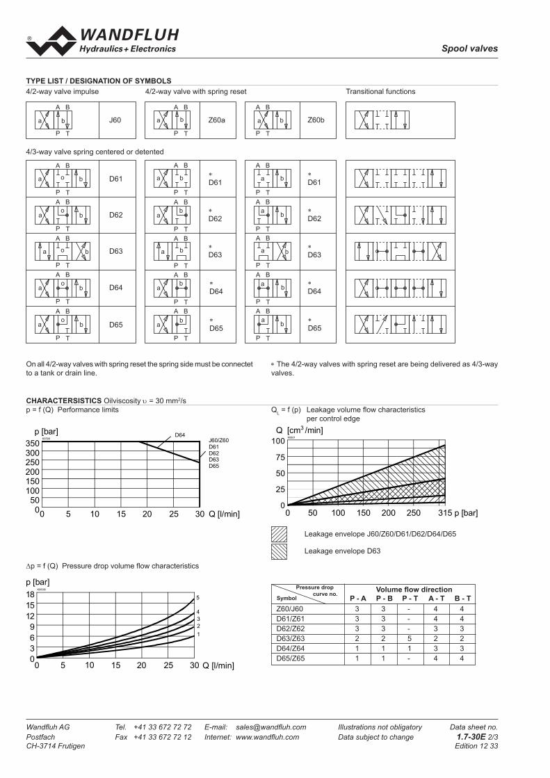
Spool valves
Wandfl uh AG Tel. +41 33 672 72 72 E-mail: sales@wandfl uh.com Illustrations not obligatory Data sheet no.
Postfach Fax +41 33 672 72 12 Internet: www.wandfl uh.com Data subject to change 1.7-30E 2/3
CH-3714 Frutigen Edition 12 33
Volume fl ow direction
P - A P - B P - T A - T B - T
Z60/J60 3 3 - 4 4
D61/Z61 3 3 - 4 4
D62/Z62 3 3 - 3 3
D63/Z63 2 2 5 2 2
D64/Z64 1 1 1 3 3
D65/Z65 1 1 - 4 4
Pressure drop
curve no.Symbol
Leakage envelope J60/Z60/D61/D62/D64/D65
Leakage envelope D63
a b
BA
P T
a b
BA
P T
o
a b
BA
P T
o
a b
BA
P T
o
a b
BA
P T
o
a b
BA
P T
a b
BA
P T
ab
BA
P T
a b
BA
P T
ab
BA
P T
ab
BA
P T
a b
BA
P T
a b
BA
P T
ab
BA
P T
a b
BA
P T
ab
BA
P T
ab
BA
P T
J 6 0
D 6 1
D 6 2
D 6 3
D 6 4
D 6 5
Z 6 0 a
*
D 6 1
*
D 6 2
*
D 6 3
*
D 6 4
*
D 6 5
Z 6 0 b
*
D 6 1
*
D 6 2
*
D 6 3
*
D 6 4
*
D 6 5
a b
BA
P T
o
TYPE LIST / DESIGNATION OF SYMBOLS
4/3-way valve spring centered or detented
4/2-way valve impulse 4/2-way valve with spring reset Transitional functions
On all 4/2-way valves with spring reset the spring side must be connectet
to a tank or drain line.
∗ The 4/2-way valves with spring reset are being delivered as 4/3-way
valves.
CHARACTERSISTICS Oilviscosity υ = 30 mm2/s
p = f (Q) Performance limits QL = f (p) Leakage volume fl ow characteristics
per control edge
∆p = f (Q) Pressure drop volume fl ow characteristics
00
p [bar]K0599
Q [l/min]5 1510 20
50100150200250300350
J60/Z60
D61
D62D63
D65
25 30
D64
00
p [bar]K0600i
Q [l/min]5 1510 20
3
6
9
12
15
18 5
4
3
2
1
25 30
p [bar]
K0601
0
25
50
75
100
0 50 100 150 200 250 315
Q [cm /min]3

Spool valves
Wandfl uh AG Tel. +41 33 672 72 72 E-mail: sales@wandfl uh.com Illustrations not obligatory Data sheet no.
Postfach Fax +41 33 672 72 12 Internet: www.wandfl uh.com Data subject to change 1.7-30E 3/3
CH-3714 Frutigen Edition 12 33
PARTS LIST
Position Article Description
10 058.4600 Cover
20 246.2121 Socket head cap screw M5 x 20 DIN 912
30 160.2093 O-ring ID 9,25 x1,78
DIMENSIONS
Technical explanation see data sheet 1.0-100
ACCESSORIES
Threaded connection plates, Multi-fl ange plates
and longitudinal stacking system register 2.9
1 0
2 0
3 0
G 1 / 8 " G 1 / 8 "
6 4
5 , 2
9 , 5
46
39
7(
)
2 2
1 0 8
2 2
45
A
T
B
P
1 7 , 8
2 1 , 5 1 9
4 0 , 5
31
32,5
21

Spool valves
Wandfl uh AG Tel. +41 33 672 72 72 E-mail: sales@wandfl uh.com Illustrations not obligatory Data sheet no.
Postfach Fax +41 33 672 72 12 Internet: www.wandfl uh.com Data subject to change 1.7-40E 1/3
CH-3714 Frutigen Edition 12 33
Spool valve hydraulic operation
• 4/2-way Impuls version detended
• 4/3-way with spring centered
• 4/2-way with spring reset
• Qmax
= 100 l/min, pmax
= 350 bar
APPLICATION
Hydraulically operated spool valves are mainly
used to control the direction of movement and
retain hydraulic cylinders and motors. The
direction of movement is determined by the
position of the valve spool and its symbol.
Hydraulically operated valves are particularly
suitable for use in installations where no electric
current is available or for applications in areas
with a risk of explosion (chemical industry,
tunnel construction).
DESCRIPTION
Spool valve NG10, fl ange type in accordance
to ISO 4401-05 with 4 connections. Direct hy-
draulic operation via pilot ports in end covers.
5 chamber system. Spool with spring return or
detented. Precise spool fi t, low leak, long life.
Threaded ports by means of additional connec-
ting plate. Hardened spool. Valve body made
of high quality casting. Valve body painted, end
covers zinc coated.
GENERAL SPECIFICATIONS
Description 4/2-, 4/3-way spool valve
Nominal size NG10 to ISO 4401-05
Construction Direct operated spool valve
Operations Hydraulic
Mounting Flange
4 fi xing holes for
socket head cap screws M6x65
Connections Threaded connection plates
Multi-fl ange plates
Longitudinal stacking system
Ambient temperature -20…50°C
Mounting position any, preferably horizontal
Fastening torque MD= 9,5 Nm (screw quality 8.8)
Weight m = 4 kg
HYDRAULIC SPECIFICATIONS
Fluid Mineral oil, other fl uid on request
Contamination effi ciency ISO 4406:1999, class 20/18/14
(Required fi ltration grade ß 10...16≥75)
refer to data sheet 1.0-50/2
Viscosity range 12 mm2/s…320 mm2/s
Fluid temperature -20…+70°C
Operating pressure
in port P, A, B pmax
= 350 bar
Tank pressure
in port T pmax
= 200 bar
resp. 12 bar below pst
Max. Volume fl ow Qmax
= 100 l/min
Leakage volume fl ow see characteristics
CONTROL HYDRAULIC
Minimal pilot pressure pst min
= 12 bar
(for AP4J100) pst min
= 2,5 bar, higher pilot pressure on request
Maximal pilot pressure pst max
= 315 bar
Control volume Vst = 1,25 cm3
FUNCTION
Pilot pressure shifts spool to end position.
• 4/2-way impulse
2 pilot ports. 2 detented spool positions. Spool
held in position by detent unless oposite pilot
port is pressurised to shift back.
• 4/3-way spring centered
2 pilot ports. 3 spool positions. Spool shifted
to center position by spring as pilot pressure
decays.
• 4/2-way spring offset
1 pilot port. 1 drain port on spring side, 2 spool
positions. Spool shifted to home position by
spring as pilot pressure decays.
CONTENT
GENERAL SPECIFICATIONS ......................1
HYDRAULIC SPECIFICATIONS ..................1
CONTROL HYDRAULIC ..............................1
TYPE CHARTS/SYMBOLS ..........................2
CHARACTERISTICS ....................................2
DIMENSIONS ...............................................3
PARTS LIST .................................................3
ACCESSORIES............................................3
TYPE CODE
A P 4 #
International interface ISO
Hydraulic operation
No. of control ports
Type charts/Symbols acc. to table 1.7-40/2
Design-Index (Subject to change)
NG10ISO 4401-05
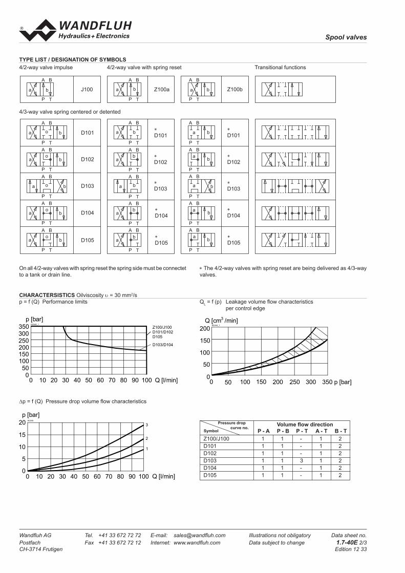
Spool valves
Wandfl uh AG Tel. +41 33 672 72 72 E-mail: sales@wandfl uh.com Illustrations not obligatory Data sheet no.
Postfach Fax +41 33 672 72 12 Internet: www.wandfl uh.com Data subject to change 1.7-40E 2/3
CH-3714 Frutigen Edition 12 33
Volume fl ow direction
P - A P - B P - T A - T B - T
Z100/J100 1 1 - 1 2
D101 1 1 - 1 2
D102 1 1 - 1 2
D103 1 1 3 1 2
D104 1 1 - 1 2
D105 1 1 - 1 2
Pressure drop
curve no.Symbol
a b
BA
P T
a b
BA
P T
o
a b
BA
P T
o
a b
BA
P T
o
a b
BA
P T
o
a b
BA
P T
a b
BA
P T
ab
BA
P T
a b
BA
P T
ab
BA
P T
ab
BA
P T
a b
BA
P T
a b
BA
P T
ab
BA
P T
a b
BA
P T
ab
BA
P T
ab
BA
P T
J 1 0 0
D 1 0 1
D 1 0 2
D 1 0 3
D 1 0 4
D 1 0 5
Z 1 0 0 a
*
D 1 0 1
*
D 1 0 2
*
D 1 0 3
*
D 1 0 4
*
D 1 0 5
Z 1 0 0 b
*
D 1 0 1
*
D 1 0 2
*
D 1 0 3
*
D 1 0 4
*
D 1 0 5
a b
BA
P T
o
TYPE LIST / DESIGNATION OF SYMBOLS
4/3-way valve spring centered or detented
4/2-way valve impulse 4/2-way valve with spring reset Transitional functions
On all 4/2-way valves with spring reset the spring side must be connectet
to a tank or drain line.
∗ The 4/2-way valves with spring reset are being delivered as 4/3-way
valves.
CHARACTERSISTICS Oilviscosity υ = 30 mm2/s
p = f (Q) Performance limits QL = f (p) Leakage volume fl ow characteristics
per control edge
∆p = f (Q) Pressure drop volume fl ow characteristics
0
p [bar]K0345
100 Q [l/min]20 40 60 80 9010 30 50 70
1
2
3
0
5
10
15
20
0
p [bar]K0346_1
100 Q [l/min]20 40 60 80 9010 30 50 70
D103/D104
Z100/J100
D101/D102
D105
050
100150200250300350 K0344_1
p [bar]
50
100
150
200
Q [cm /min]3
00 50 100 150 200 250 300 350

Spool valves
Wandfl uh AG Tel. +41 33 672 72 72 E-mail: sales@wandfl uh.com Illustrations not obligatory Data sheet no.
Postfach Fax +41 33 672 72 12 Internet: www.wandfl uh.com Data subject to change 1.7-40E 3/3
CH-3714 Frutigen Edition 12 33
Position Article Description
10 059.2206 Cover
20 173.1503 Pilot plate NG4-Mini
30 246.3131 Socket head cap screw M6x30 DIN 912
40 246.2126 Socket head cap screw M5x25 DIN 912
50 160.2052 O-ring ID 5,28x1,78
60 160.2140 O-ring ID 14,00x1,78
PARTS LIST
DIMENSIONS
Technical explanation see data sheet 1.0-100
ACCESSORIES
Threaded connection plates, Multi-fl ange plates
and longitudinal stacking system register 2.9
54
20,8
48
1,5
9,7
16,8
46
A
P
T
B
To
93
148,6
60
G1/8"
54
87
62
7()
55
()
AB
10
2040
50
60
30
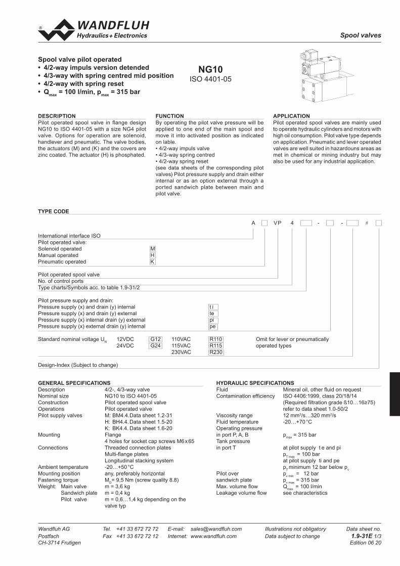
Spool valves
Wandfl uh AG Tel. +41 33 672 72 72 E-mail: sales@wandfl uh.com Illustrations not obligatory Data sheet no.
Postfach Fax +41 33 672 72 12 Internet: www.wandfl uh.com Data subject to change 1.9-31E 1/3
CH-3714 Frutigen Edition 06 20
Spool valve pilot operated
• 4/2-way impuls version detended
• 4/3-way with spring centred mid position
• 4/2-way with spring reset
• Qmax
= 100 l/min, pmax
= 315 bar
DESCRIPTION
Pilot operated spool valve in fl ange design
NG10 to ISO 4401-05 with a size NG4 pilot
valve. Options for operation are solenoid,
handlever and pneumatic. The valve bodies,
the actuators (M) and (K) and the covers are
zinc coated. The actuator (H) is phosphated.
FUNCTION
By operating the pilot valve pressure will be
applied to one end of the main spool and
move it into activated position as indicated
on lable.
• 4/2-way impuls valve
• 4/3-way spring centred
• 4/2-way spring reset
(see data sheets of the corresponding pilot
valves) Pilot pressure supply and drain either
internal or as an option external through a
ported sandwich plate between main and
pilot valve.
GENERAL SPECIFICATIONS
Description 4/2-, 4/3-way valve
Nominal size NG10 to ISO 4401-05
Construction Pilot operated spool valve
Operations Pilot operated valve
Pilot supply valves M: BM4.4. Data sheet 1.2-31
H: BH4.4. Data sheet 1.5-20
K: BK4.4. Data sheet 1.6-20
Mounting Flange
4 holes for socket cap screws M6 x 65
Connections Threaded connection plates
Multi-fl ange plates
Longitudinal stacking system
Ambient temperature -20…+50 °C
Mounting position any, preferably horizontal
Fastening torque MD= 9,5 Nm (screw quality 8.8)
Weight: Main valve m = 3,6 kg
Sandwich plate m = 0,4 kg
Pilot valve m = 0,6…1,4 kg depending on the
valve typ
HYDRAULIC SPECIFICATIONS
Fluid Mineral oil, other fl uid on request
Contamination effi ciency ISO 4406:1999, class 20/18/14
(Required fi ltration grade ß10…16≥75)
refer to data sheet 1.0-50/2
Viscosity range 12 mm2/s…320 mm2/s
Fluid temperature -20…+70 °C
Operating pressure
in port P, A, B pmax
= 315 bar
Tank pressure
in port T at pilot supply t e and pi
pT max
= 100 bar
at pilot supply ti and pe
pT minimum 12 bar below p
v
Pilot over pv min
= 12 bar
sandwich plate pv max
= 315 bar
Max. volume fl ow Qmax
= 100 l/min
Leakage volume fl ow see characteristics
APPLICATION
Pilot operated spool valves are mainly used
to operate hydraulic cylinders and motors with
high oil consumption. Pilot valve type depends
on application. Pneumatic and lever operated
valves are well suited in hazardouns areas as
met in chemical or mining industry but may
also be used for any industrial application.
TYPE CODE
A VP 4 - - #
International interface ISO
Pilot operated valve:
Solenoid operated M
Manual operated H
Pneumatic operated K
Pilot operated spool valve
No. of control ports
Type charts/Symbols acc. to table 1.9-31/2
Pilot pressure supply and drain:
Pressure supply (x) and drain (y) internal t i
Pressure supply (x) and drain (y) external te
Pressure supply (x) internal drain (y) external pi
Pressure supply (x) external drain (y) internal pe
Standard nominal voltage UN 12VDC G12 110VAC R110 Omit for lever or pneumatically
24VDC G24 115VAC R115 operated types
230VAC R230
Design-Index (Subject to change)
NG10ISO 4401-05
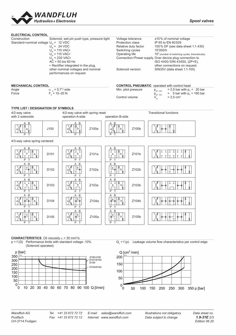
Spool valves
Wandfl uh AG Tel. +41 33 672 72 72 E-mail: sales@wandfl uh.com Illustrations not obligatory Data sheet no.
Postfach Fax +41 33 672 72 12 Internet: www.wandfl uh.com Data subject to change 1.9-31E 2/3
CH-3714 Frutigen Edition 06 20
Construction Solenoid, wet pin push type, pressure tight
Standard-nominal voltage UN = 12 VDC
UN = 24 VDC
UN = 110 VAC∗
UN = 115 VAC∗
UN
= 230 VAC∗
AC = 50 bis 60 Hz
∗ Rectifi er integrated in the plug,
other nominal voltages and nominal
performances on request
Voltage tolerance ±10 % of nominal voltage
Protection class IP 65 to EN 60 529
Relative duty factor 100 % DF (see data sheet 1.1-430)
Switching cycles 15’000/h
Operating life 107 (number of switching cycles, theoretically)
Connection / Power supply Over device plug connection to
ISO 4400 / DIN 43 650, (2P+E),
other connections on request.
Solenoid version: SIN35V (data sheet 1.1-105)
MECHANICAL CONTROL
Angle α b = 5,7°/ side
Force Fb = 15–20 N
CONTROL PNEUMATIC operated with control head
Min. pilot pressure pst,
min = 2,5 bar with p
T = 20 bar
pst,
min = 5 bar with p
T = 160 bar
Control volume Vst = 2,5 cm3
ELECTRICAL CONTROL
TYPE LIST / DESIGNATION OF SYMBOLS
4/3-way valve spring centered
4/2-way valve 4/2-way valve with spring reset Transitional functions
with 2 solenoids operation A-side operation B-side
a b
BA
P T
a b
BA
P T
o
BA
P T
o
a b
BA
P T
o
a b
BA
P T
o
a b
BA
P T
a b
BA
P T
ab
BA
P T
b
BA
P T
ab
BA
P T
ab
BA
P T
a b
BA
P T
a b
BA
P T
ab
BA
P T
a
BA
P T
ab
BA
P T
ab
BA
P T
J 1 0 0
D 1 0 1
D 1 0 2
D 1 0 3
D 1 0 4
D 1 0 5
Z 1 0 0 a
Z 1 0 1 a
Z 1 0 2 a
Z 1 0 3 a
Z 1 0 4 a
Z 1 0 5 a
Z 1 0 0 b
Z 1 0 1 b
Z 1 0 2 b
Z 1 0 3 b
Z 1 0 4 b
Z 1 0 5 b
a b
BA
P T
o
a b a b
CHARACTERISTICS Oil viscosity υ = 30 mm2/s
p = f (Q) Performance limits with standard voltage -10% QL = f (p) Leakage volume fl ow characteristics per control edge
(Solenoid operated)
0
p [bar]K0346
100 Q [l/min]20 40 60 80 9010 30 50 70
D103/D104
Z100/J100D101/D102
D105
050
100150200250300350
K0344
p [bar]
50
100
150
200
Q [cm /min]3
00 50 100 150 200 250 300 350

Spool valves
Wandfl uh AG Tel. +41 33 672 72 72 E-mail: sales@wandfl uh.com Illustrations not obligatory Data sheet no.
Postfach Fax +41 33 672 72 12 Internet: www.wandfl uh.com Data subject to change 1.9-31E 3/3
CH-3714 Frutigen Edition 06 20
∆p = f (Q) Pressure drop volume fl ow characteristics
DIMENSIONS
Pilot supply ti and pi
Pilot supply te and pe
Volume fl ow direction
P - A P - B P - T A - T B - T
Z100/J100 1 1 - 1 2
D101/Z101 1 1 - 1 2
D102/Z102 1 1 - 1 2
D103/Z103 4 4 5 1 2
D104/Z104 4 4 - 1 2
D105/Z105 1 1 - 1 2
Pressure drop
curve no.Symbol
Volume fl ow direction
P - A P - B P - T A - T B - T
Z100/J100 1 1 - 1 2
D101/Z101 1 1 - 1 2
D102/Z102 1 1 - 1 2
D103/Z103 1 1 3 1 2
D104/Z104 1 1 - 1 2
D105/Z105 1 1 - 1 2
Pressure drop
curve no.Symbol
PARTS LIST
Position Article Description
10 059.2206 Cover
20 246.3131 Socket head cap screw M6 x 30 DIN 912
30 246.2141 Socket head cap screw M5 x 40 DIN 912
for pilot supply ti
246.2160 Socket head cap screw M5 x 60
for pilot supply te, pi and pe
40 160.2052 O-ring ID 5,28 x1,78
50 160.2140 O-ring ID 14,00 x1,78
60 238.1405 Plug screw G1/8"
ACCESSORIES
Threaded connecting plates, Multi-fl ange subplates and
Longitudinal stacking system see Reg. 2.9
Technical explanation see data sheet 1.0-100
Y = G 1 / 8 "
X = G 1 / 8 "
1 0
2 0
3 0 4 0
5 0
6 0 , 7 0
1 4 8 , 6
9 3
60
62
82
55
7(
)
5 4
1 0 , 5
6 , 5
BA
T
P
T o
5 4
1,5
9,7
16,8
2 0 , 8
4 8
46
Mounting instruction
To screw the main valve body (MD = 9,5 Nm, quality 8.8) to the base
plate the pilot valve (MD = 5,5 Nm, quality 8.8) must be taken off.
60
p [bar]
0
K0347
100 Q [l/min]20 40 60 80 9010 30 50 70
3
2
1
0
5
10
15
204
5

Module type manifold systems
Wandfluh AG Tel. +41 33 672 72 72 E-mail: [email protected] Illustrations not obligatory Data sheet no.Postfach Fax +41 33 672 72 12 Internet: www.wandfluh.com Data subject to change 2.9-100E 1/2CH-3714 Frutigen Edition 03 26
Module type manifold blocks• pmax = 350 bar
functionThe module type manifold blocks are available with 3 different basic circuits, namely parallel, serial and pressure reduction circuit.
applicationThis block system can be used as a replace-ment for expensive special blocks. Existing systems may be exended or reduced by adding as removing modular blocks.
General specificationsDescription Parallel-, serial- and pressure reduction circuitNominal size NG6 acc. to ISO 4401-03Fastening see data sheet 2.9-124Connection Threaded connections P, Pred T1, A, B = G3/8“ T = G1/2“Mounting position anyWeight: m = 2,0 kg
descriptionModule type manifold blocks with interface NG6 acc. to ISO 4401-03. Using an adapter plate and connecting blocks, combinations with NG3-Mini, NG4-Mini and NG10 are also possible (see also data sheet 2.9-80). The module type manifold blocks are made from steel and are phosphated.
type code A LV 6 #
International standard interface ISO
Module type manifold
Nominal size 6
Type listParallel circuit PSerial circuit SPressure reduction circuit D
Design-Index (Subject to change)
Hydraulic specificationsWorking pressure pmax = 350 bar
syMBols
Block for parallel circuitALV6P
Block for serial circuitALV6S
Block for pressure reduction circuitALV6D
nG6ISO 4401-03
P
T
A B
P
T
T1
T
A B
P
T
Pred
T
A B
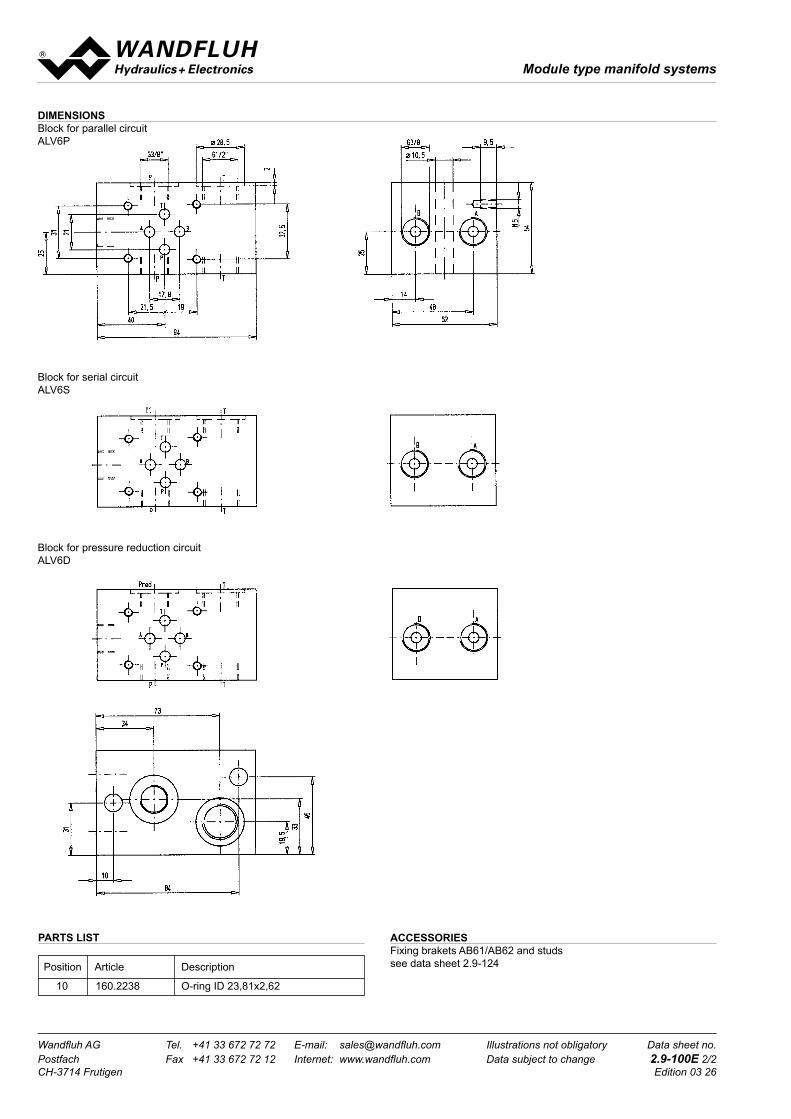
Module type manifold systems
Wandfluh AG Tel. +41 33 672 72 72 E-mail: [email protected] Illustrations not obligatory Data sheet no.Postfach Fax +41 33 672 72 12 Internet: www.wandfluh.com Data subject to change 2.9-100E 2/2CH-3714 Frutigen Edition 03 26
diMensionsBlock for parallel circuitALV6P
Block for serial circuitALV6S
Block for pressure reduction circuitALV6D
accessoriesFixing brakets AB61/AB62 and studs see data sheet 2.9-124
parts list
Position Article Description
10 160.2238 O-ring ID 23,81x2,62