Embed Size (px)
Citation preview
102
VALVES GENERAL CATALOG
INDEX
SOLENOID VALVESSERIES,
Before use, be sure to read the “Safety Precautions” on p. 31.Caution
Features 103Product Range 104Handling Instructions and Precautions 105EA Series
Specifications 109Order Codes 113Dimensions 116
EB SeriesSpecifications 121Order Codes 125Dimensions 128
SOLE
NOID
VAL
VES
EA, E
B SE
RIES
103
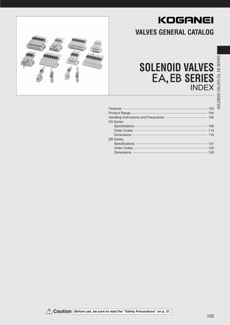
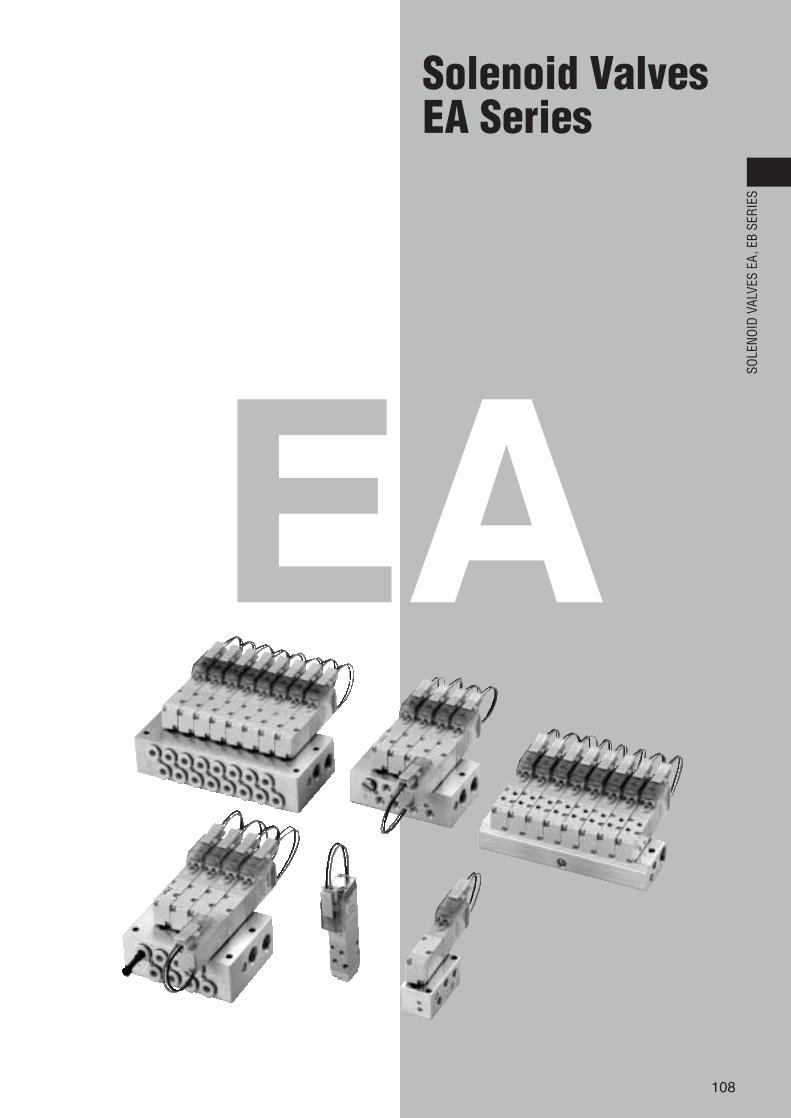
Small, easy-to-use, simple construction valves!Suitable for various needs and offering high-performancecontrol, while achieving still lower power consumption and quicker response!
SOLENOID VALVES
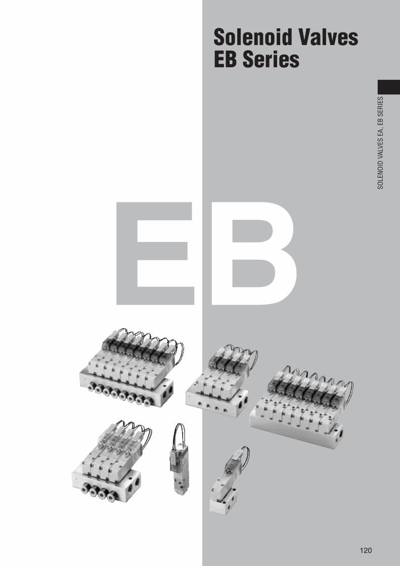
EB series(2, 3-port pilot type solenoid valves)
SOLENOID VALVES
EA series(2, 3, 5-port pilot type solenoid valves)
Space Saving—Thin and compact sizeValve width: 10mm [0.394in.]Valve length: 56.7mm [2.232in.] (EA series)
53mm [2.087in.] (EB series)(for standard type)
Flow—Efficient flow rateSonic conductance C: 0.26dm3/(s·bar)(Effective area: 1.3mm2〔Cv: 0.07〕)Optimum for pilot-operated valves, and for operating up to φ25 [0.984in.] bore size cylinders.
Response—Fast response timeResponse time: When ON, 6ms or below
When OFF, 7ms or below(in the case of quick response type single solenoids)
Power—Lower power consumptionStandard type: 0.55W, Low current type: 0.15W
Reliability—Improved reliabilityNew solenoid and stem construction resulting fromyears of our valve technology experience haveboosted operating life, response, and other basicperformance features.
Environmental Protection—Improved performanceGrommet type valves offer moisture proof specifications.
Provides reliable performance for allsituations in which solenoid valves arerequired, in the manufacturing lines, inmachinery, or in equipment.A NEW standard in compact valves!
10mm
56.7
mm
10mm
53m
m
SOLENOID VALVES SERIES,
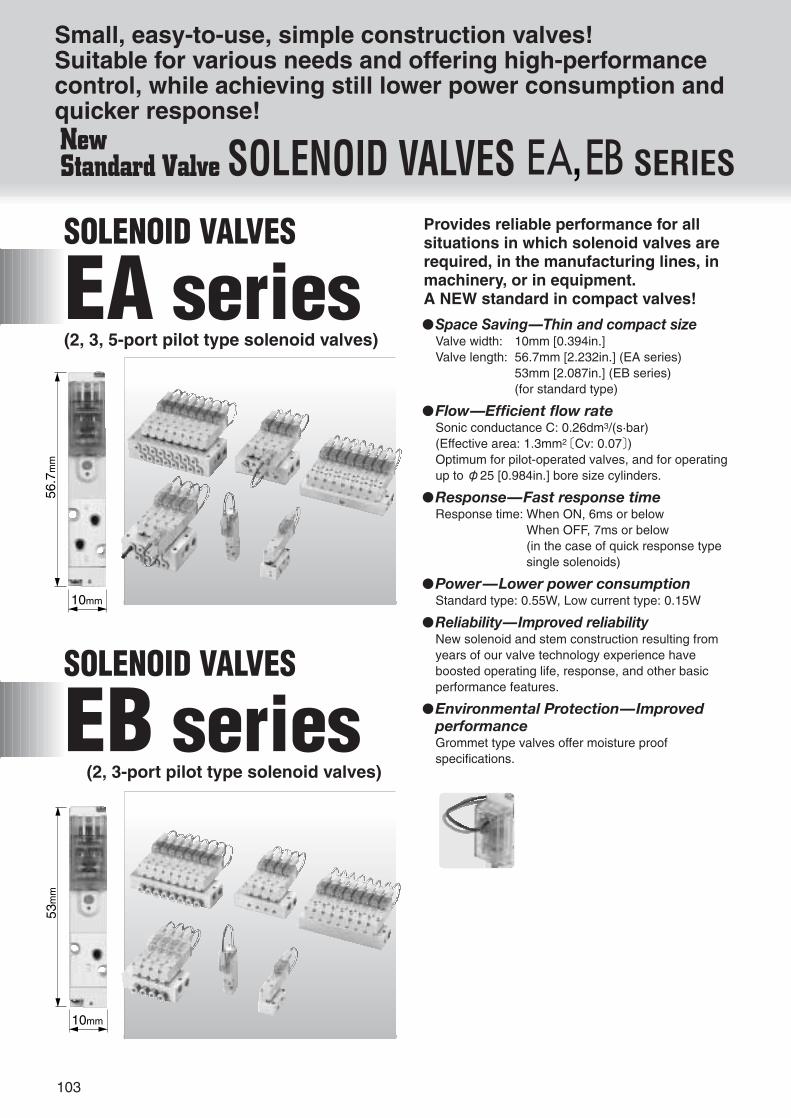
—Product Variety—
Providing a wide product range
Single unit (direct piping) Single
solenoidNormally closed (NC) Normally open (NO)Double
solenoid
Single unit (base piping)
F type manifold (direct piping type)
A, AJ type manifolds(base piping type)
Function-specificsolenoids (for both EA and EB series)
Standard, low current andquick response types canbe identified by the color oftheir housings.
Standard type: Blue Low current type: Light blue Quick response type: White
EA10F5 EA10F6EB10F1EB10F3
EB10F2EB10F4
Single solenoid
Normally closed (NC)
Manifold for combination mounting of 2, 3, 5-port valves Manifold for 2, 3-port valves
Manifold for combination mounting of 2, 3, 5-port valves Manifold for 2, 3-port valves
Normally open (NO)Double solenoid
EA10A5-25 EA10A6-25EB10A1-25EB10A3-25
EAMF EBMF
EB10A2-25EB10A4-25
EAMA EAMAJ EBMA EBMAJ
116
116
118
118
128
128
129
129
104
SOLE
NOID
VAL
VES
EA, E
B SE
RIES
(2, 3-portvalves)Solenoid Valves EA Series Solenoid Valves EB Series
105
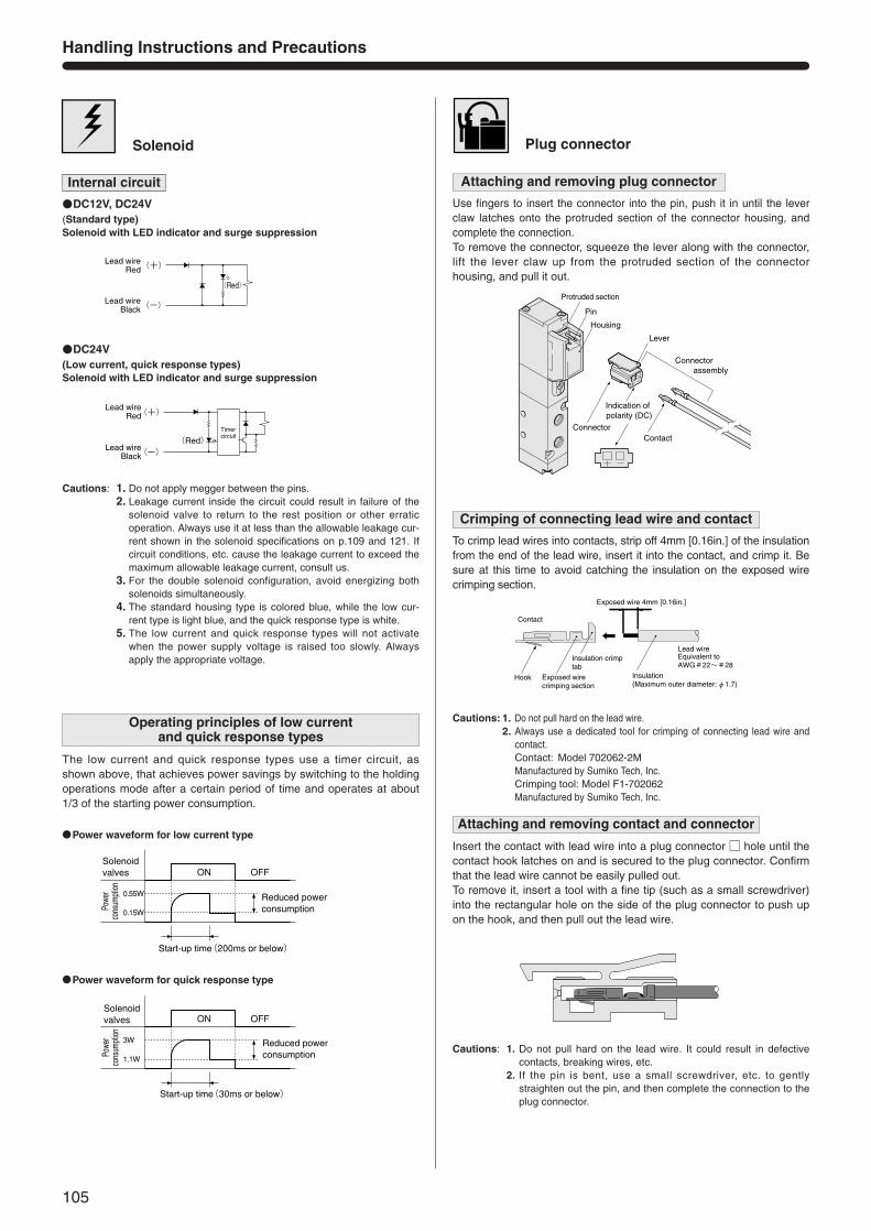
Solenoid
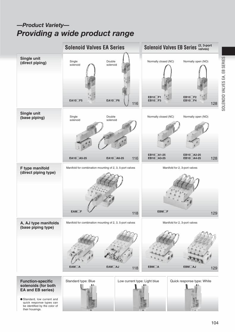
Handling Instructions and Precautions
The low current and quick response types use a timer circuit, asshown above, that achieves power savings by switching to the holdingoperations mode after a certain period of time and operates at about1/3 of the starting power consumption.
DC12V, DC24V
DC24V
Internal circuit
(-)
(+)
(Red)Timer circuit
Lead wireRed
Lead wireBlack
(Standard type)Solenoid with LED indicator and surge suppression
(Low current, quick response types)Solenoid with LED indicator and surge suppression
ON
OFF
0.15W
0.55W
Solenoid valves
Powe
rco
nsum
ption
Start-up time(200ms or below)
Reduced power consumption
(-)
(+)Lead wireRed
Lead wireBlack
(Red)
Plug connector
Attaching and removing plug connector
Use fingers to insert the connector into the pin, push it in until the leverclaw latches onto the protruded section of the connector housing, andcomplete the connection.To remove the connector, squeeze the lever along with the connector,lift the lever claw up from the protruded section of the connectorhousing, and pull it out.
Crimping of connecting lead wire and contact
To crimp lead wires into contacts, strip off 4mm [0.16in.] of the insulationfrom the end of the lead wire, insert it into the contact, and crimp it. Besure at this time to avoid catching the insulation on the exposed wirecrimping section.
Attaching and removing contact and connector
Insert the contact with lead wire into a plug connector hole until thecontact hook latches on and is secured to the plug connector. Confirmthat the lead wire cannot be easily pulled out.To remove it, insert a tool with a fine tip (such as a small screwdriver)into the rectangular hole on the side of the plug connector to push upon the hook, and then pull out the lead wire.
Housing
Protruded section
Pin
ConnectorContact
Lever
Connector assembly
Indication of polarity (DC)
Hook Exposed wire crimping section
Insulation crimp tab
Contact
Exposed wire 4mm [0.16in.]
Lead wire
Insulation (Maximum outer diameter:φ1.7)
Equivalent to AWG#22~#28
Power waveform for low current type
ON
OFF
1.1W
3W
Solenoid valves
Powe
rco
nsum
ption
Start-up time(30ms or below)
Reduced power consumption
Power waveform for quick response type
Cautions: 1. Do not apply megger between the pins.2. Leakage current inside the circuit could result in failure of the
solenoid valve to return to the rest position or other erraticoperation. Always use it at less than the allowable leakage cur-rent shown in the solenoid specifications on p.109 and 121. Ifcircuit conditions, etc. cause the leakage current to exceed themaximum allowable leakage current, consult us.
3. For the double solenoid configuration, avoid energizing bothsolenoids simultaneously.
4. The standard housing type is colored blue, while the low cur-rent type is light blue, and the quick response type is white.
5. The low current and quick response types will not activatewhen the power supply voltage is raised too slowly. Alwaysapply the appropriate voltage.
Operating principles of low current and quick response types
Cautions: 1. Do not pull hard on the lead wire.2. Always use a dedicated tool for crimping of connecting lead wire and
contact.Contact: Model 702062-2MManufactured by Sumiko Tech, Inc.Crimping tool: Model F1-702062Manufactured by Sumiko Tech, Inc.
Cautions: 1. Do not pull hard on the lead wire. It could result in defectivecontacts, breaking wires, etc.
2. If the pin is bent, use a small screwdriver, etc. to gentlystraighten out the pin, and then complete the connection to theplug connector.
106
SOLE
NOID
VAL
VES
EA, E
B SE
RIES
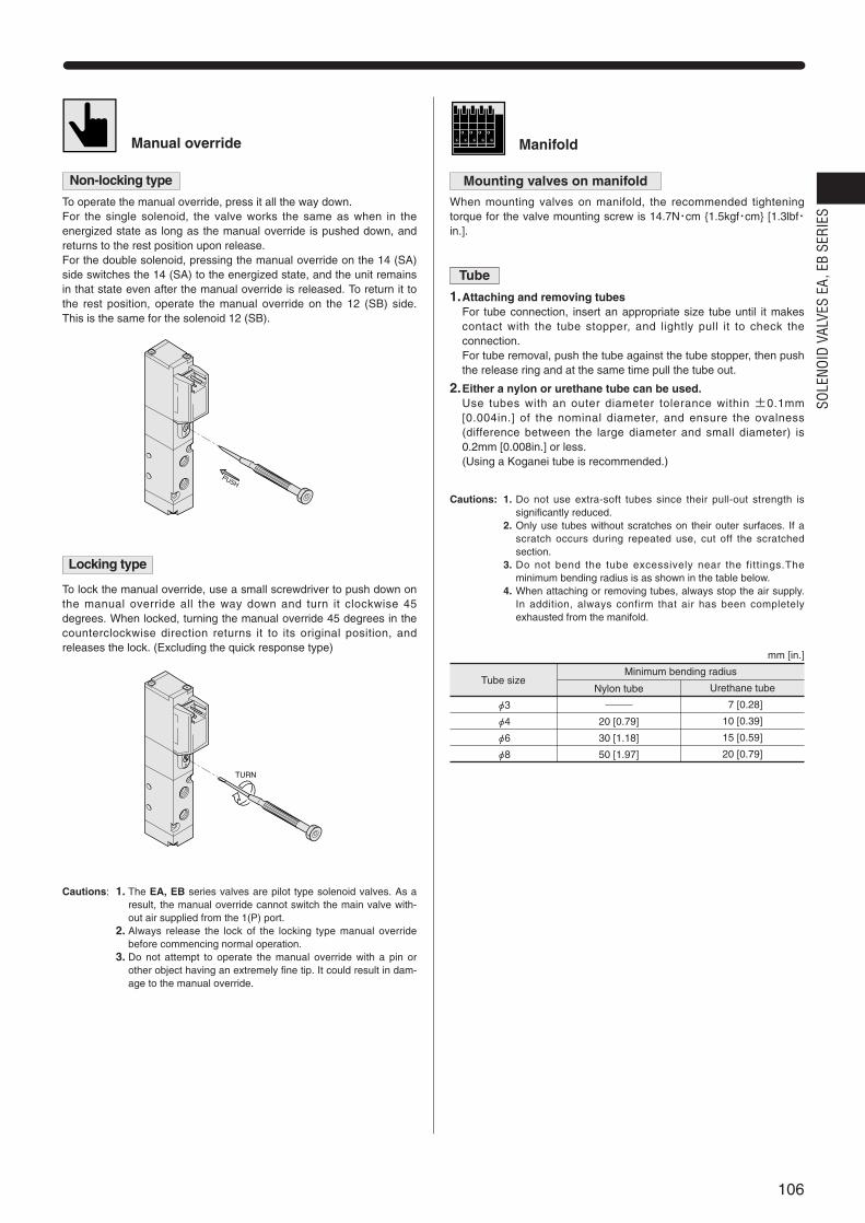
Mounting valves on manifold
When mounting valves on manifold, the recommended tighteningtorque for the valve mounting screw is 14.7N・cm 1.5kgf・cm [1.3lbf・in.].
Tube
1.Attaching and removing tubesFor tube connection, insert an appropriate size tube until it makescontact with the tube stopper, and lightly pull it to check theconnection.For tube removal, push the tube against the tube stopper, then pushthe release ring and at the same time pull the tube out.
2.Either a nylon or urethane tube can be used.Use tubes with an outer diameter tolerance within ±0.1mm[0.004in.] of the nominal diameter, and ensure the ovalness(difference between the large diameter and small diameter) is0.2mm [0.008in.] or less.(Using a Koganei tube is recommended.)
Tube size
φ3
φ4
φ6
φ8
Nylon tube
20 [0.79]
30 [1.18]
50 [1.97]
Urethane tube
17 [0.28]
10 [0.39]
15 [0.59]
20 [0.79]
mm [in.]
ManifoldManual override
Non-locking type
To operate the manual override, press it all the way down. For the single solenoid, the valve works the same as when in theenergized state as long as the manual override is pushed down, andreturns to the rest position upon release.For the double solenoid, pressing the manual override on the 14 (SA)side switches the 14 (SA) to the energized state, and the unit remainsin that state even after the manual override is released. To return it tothe rest position, operate the manual override on the 12 (SB) side.This is the same for the solenoid 12 (SB).
Locking type
To lock the manual override, use a small screwdriver to push down onthe manual override all the way down and turn it clockwise 45degrees. When locked, turning the manual override 45 degrees in thecounterclockwise direction returns it to its original position, andreleases the lock. (Excluding the quick response type)
PUSH
TURN
Minimum bending radius
Cautions: 1. The EA, EB series valves are pilot type solenoid valves. As aresult, the manual override cannot switch the main valve with-out air supplied from the 1(P) port.
2. Always release the lock of the locking type manual overridebefore commencing normal operation.
3. Do not attempt to operate the manual override with a pin orother object having an extremely fine tip. It could result in dam-age to the manual override.
Cautions: 1. Do not use extra-soft tubes since their pull-out strength issignificantly reduced.
2. Only use tubes without scratches on their outer surfaces. If ascratch occurs during repeated use, cut off the scratchedsection.
3. Do not bend the tube excessively near the fittings.Theminimum bending radius is as shown in the table below.
4. When attaching or removing tubes, always stop the air supply.In addition, always confirm that air has been completelyexhausted from the manifold.

107
EA
108
SOLE
NOID
VAL
VES
EA, E
B SE
RIES
Solenoid ValvesEA Series
109
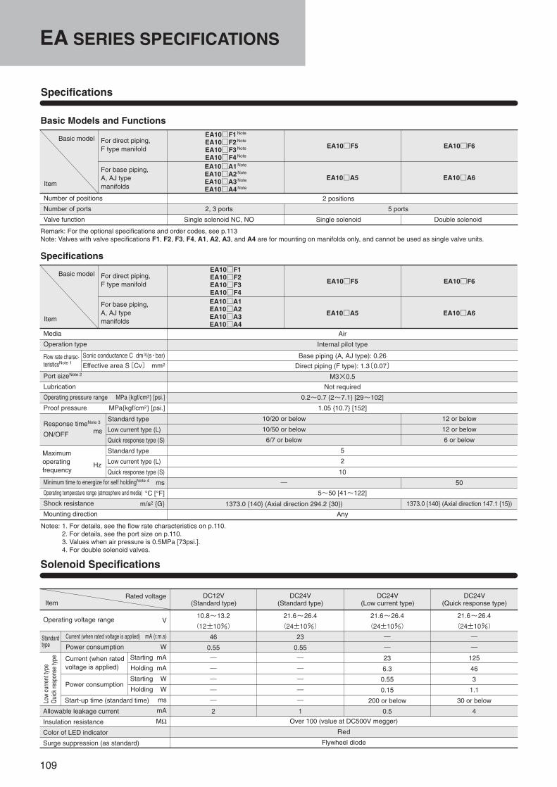
EA SERIES SPECIFICATIONS
Air
Internal pilot type
Not required
0.2~0.7 2~7.1 [29~102]
1.05 10.7 [152]
5
2
5~50 [41~122]
Any
Media
Operation type
Port sizeNote 2
Lubrication
Operating pressure range MPa kgf/cm2 [psi.]
Proof pressure MPakgf/cm2 [psi.]
Response timeNote 3
ON/OFF
Minimum time to energize for self holdingNote 4
Operating temperature range (atmosphere and media)
Shock resistance
Mounting direction
Specifications
Basic Models and Functions
Specifications
Basic model
Item
Number of positions
Number of ports
Valve function
EA10F1Note
EA10F2Note
EA10F3Note
EA10F4Note
EA10F5 EA10F6
EA10A1Note
EA10A2Note
EA10A3Note
EA10A4Note
EA10A5 EA10A6
2 positions
5 ports
Notes: 1. For details, see the flow rate characteristics on p.110.2. For details, see the port size on p.110.3. Values when air pressure is 0.5MPa [73psi.].4. For double solenoid valves.
Remark: For the optional specifications and order codes, see p.113Note: Valves with valve specifications F1, F2, F3, F4, A1, A2, A3, and A4 are for mounting on manifolds only, and cannot be used as single valve units.
Solenoid Specifications
Rated voltageItem
10.8~13.2
(12±10%)
46
0.55
―
―
―
―
―
2
21.6~26.4
(24±10%)
23
0.55
―
―
―
―
―
1Over 100 (value at DC500V megger)
Red
Flywheel diode
21.6~26.4
(24±10%)
―
―
23
6.3
0.55
0.15
200 or below
0.5
21.6~26.4
(24±10%)
―
―
125
46
3
1.1
30 or below
4
2, 3 ports
Single solenoid NC, NO Single solenoid Double solenoid
10/20 or below
10/50 or below
6/7 or below
10
―
1373.0 140 (Axial direction 294.2 30)
12 or below
12 or below
6 or below
50
1373.0 140 (Axial direction 147.1 15)
Base piping (A, AJ type): 0.26
Direct piping (F type): 1.3〔0.07〕
M3×0.5
For direct piping, F type manifold
For base piping, A, AJ typemanifolds
Basic model
Item
EA10F1EA10F2EA10F3EA10F4
EA10F5 EA10F6
EA10A1EA10A2EA10A3EA10A4
EA10A5 EA10A6
For direct piping, F type manifold
For base piping, A, AJ typemanifolds
Flow rate charac-teristicsNote 1
Sonic conductance C dm3/(s・bar)
Effective area S〔Cv〕 mm2
ms
Hz
Standard type
Low current type (L)
Quick response type (S)
Standard type
Low current type (L)
Quick response type (S)
ms
°C [°F]
m/s2 G
Low
curre
ntty
peQ
uick
resp
onse
type
Standardtype
Operating voltage range
Current (when rated voltage is applied)
Power consumption
Current (when ratedvoltage is applied)
Power consumption
Start-up time (standard time)
Allowable leakage current
Insulation resistance
Color of LED indicator
Surge suppression (as standard)
V
mA (r.m.s)
W
Starting mA
Holding mA
Starting W
Holding W
ms
mA
MΩ
DC12V(Standard type)
DC24V(Standard type)
DC24V(Low current type)
DC24V(Quick response type)
Maximumoperatingfrequency
110
SOLE
NOID
VAL
VES
EA, E
B SE
RIES
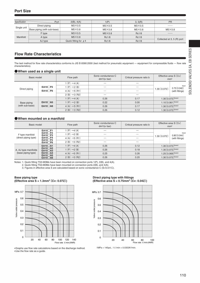
Port Size
Direct piping
Base piping (with sub-base)
F type
A type
AJ type
Single unit
Manifold
2(B), 4(A)
M3×0.5
M5×0.8
M3×0.5
M5×0.8
Quick fitting for φ4
1(P)
M3×0.5
M5×0.8
M5×0.8
Rc1/8
Rc1/8
3, 5(R)
M3×0.5
M5×0.8
Rc1/8
Rc1/8
Rc1/8
PR
M5×0.8
Collected at 3, 5 (R) port
EA10F5
EA10F6
EA10A5
EA10A6
Direct piping
Base piping(with sub-base)
―
―
―
―
0.26
0.22
0.26
0.26
―
―
―
―
0.17
0.00
0.17
0.12
1.30〔0.072〕 0.75〔0.042〕(with fittings)
1(P)→4(A)
1(P)→2(B)
4(A)→5(R1)
2(B)→3(R2)
1(P)→4(A)
1(P)→2(B)
4(A)→5(R1)
2(B)→3(R2)
1.30〔0.072〕Note3
1.10〔0.061〕Note3
1.30〔0.072〕Note3
1.30〔0.072〕Note3
When used as a single unit
Base piping type (Effective area S = 1.3mm2〔Cv: 0.072〕)
Direct piping type with fittings (Effective area S = 0.75mm2〔Cv: 0.042〕)
The test method for flow rate characteristics conforms to JIS B 8390:2000 (test method for pneumatic equipment — equipment for compressible fluids — flow ratecharacteristics).
Notes: 1. Quick fitting TS3-M3Ms have been mounted on connection ports 1(P), 2(B), and 4(A).2. Quick fitting TS3-M3Ms have been mounted on connection ports 2(B), and 4(A).3. Figures in effective area S are calculated based on sonic conductance C (S=5.0×C).
Flow Rate Characteristics
Basic model Flow path Critical pressure ratio bEffective area S〔Cv〕
mm2
Sonic conductance Cdm3/(s・bar)
EA10F1EA10F2EA10F3EA10F4EA10F5EA10F6EA10A1EA10A2EA10A3EA10A4EA10A5EA10A6
F type manifold(direct piping type)
A, AJ type manifolds(base piping type)
―
―
―
―
0.26
0.26
0.25
0.26
―
―
―
―
0.12
0.18
0.26
0.20
1.30〔0.072〕 0.80〔0.044〕(with fittings)
1(P)→4(A)
1(P)→2(B)
4(A)→5(R1)
2(B)→3(R2)
1(P)→4(A)
1(P)→2(B)
4(A)→5(R1)
2(B)→3(R2)
1.30〔0.072〕Note3
1.30〔0.072〕Note3
1.25〔0.069〕Note3
1.30〔0.072〕Note3
When mounted on a manifold
Basic model Flow path Critical pressure ratio bEffective area S〔Cv〕
mm2
Sonic conductance Cdm3/(s・bar)
Specification Port
020 40 60 80 100 120 140 20 40 60 80 100
0.2
0.4
0.6
0.1
0.3
0.5
MPa 0.7
0
0.2
0.4
0.6
0.1
0.3
0.5
MPa 0.7
Flow rate R/min(ANR) Flow rate R/min(ANR)
Val
ve o
utle
t pre
ssur
e
Val
ve o
utle
t pre
ssur
e
Graphs use flow rate calculations based on the discharge method. Use the flow rate as a guide.
1MPa = 145psi., 1R/min = 0.0353ft.3/min.
Note1
Note2
111
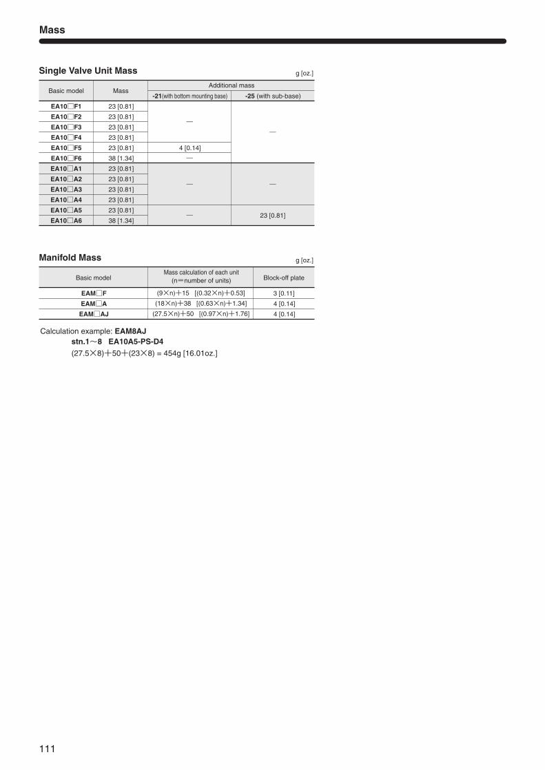
Single Valve Unit Mass
Mass
g [oz.]
Calculation example: EAM8AJstn.1~8 EA10A5-PS-D4
(27.5×8)+50+(23×8) = 454g [16.01oz.]
Basic model
EA10F1
EA10F2
EA10F3
EA10F4
EA10F5
EA10F6
EA10A1
EA10A2
EA10A3
EA10A4
EA10A5
EA10A6
Mass
23 [0.81]
23 [0.81]
23 [0.81]
23 [0.81]
23 [0.81]
38 [1.34]
23 [0.81]
23 [0.81]
23 [0.81]
23 [0.81]
23 [0.81]
38 [1.34]
-21(with bottom mounting base)
―
4 [0.14]
―
―
―
Additional mass
-25 (with sub-base)
―
―
23 [0.81]
Manifold Mass g [oz.]
Basic model
EAMF
EAMA
EAMAJ
Mass calculation of each unit(n=number of units)
(9×n)+15 [(0.32×n)+0.53]
(18×n)+38 [(0.63×n)+1.34]
(27.5×n)+50 [(0.97×n)+1.76]
Block-off plate
3 [0.11]
4 [0.14]
4 [0.14]
112
SOLE
NOID
VAL
VES
EA, E
B SE
RIES
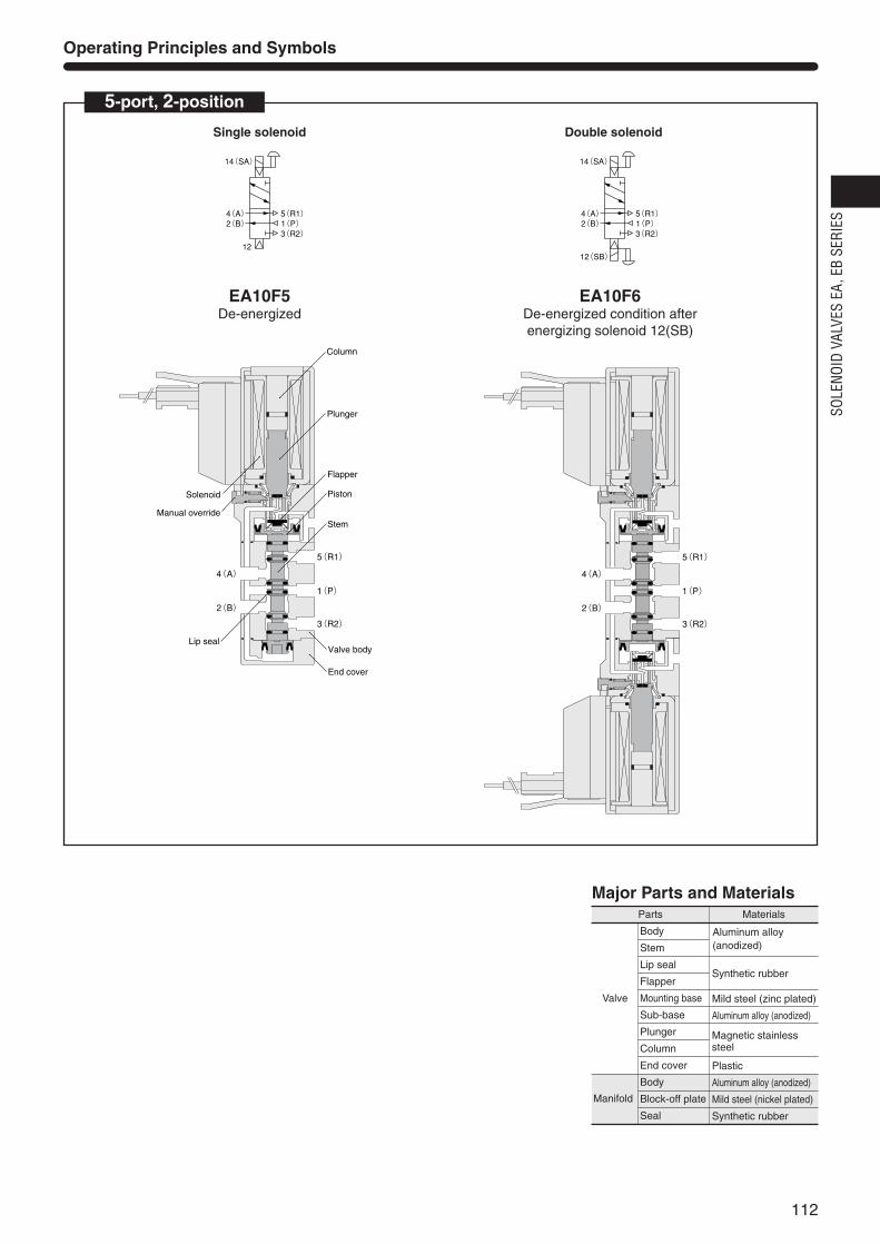
Operating Principles and Symbols
5-port, 2-position
12
4(A)2(B)
14(SA)
3(R2)
5(R1)1(P)
Single solenoid
5(R1)
4(A)
2(B)
1(P)
3(R2)
Column
Plunger
Piston
Stem
Valve body
End cover
Lip seal
Flapper
Manual override
Solenoid
5(R1)
4(A)
2(B)
1(P)
3(R2)
EA10F5De-energized
4(A)2(B)
12(SB)
14(SA)
3(R2)
5(R1)1(P)
Double solenoid
EA10F6De-energized condition afterenergizing solenoid 12(SB)
Parts
Valve
Manifold
Materials
Body
Stem
Lip seal
Flapper
Mounting base
Sub-base
Plunger
Column
End cover
Body
Block-off plate
Seal
Synthetic rubber
Mild steel (zinc plated)
Aluminum alloy (anodized)
Plastic
Aluminum alloy (anodized)
Mild steel (nickel plated)
Synthetic rubber
Major Parts and Materials
Aluminum alloy(anodized)
Magnetic stainlesssteel
Locking typeNote4
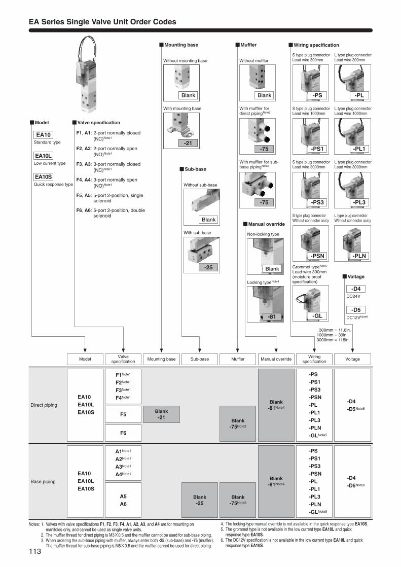
EA Series Single Valve Unit Order Codes
Notes: 1. Valves with valve specifications F1, F2, F3, F4, A1, A2, A3, and A4 are for mounting on manifolds only, and cannot be used as single valve units.
2. The muffler thread for direct piping is M3×0.5 and the muffler cannot be used for sub-base piping.3. When ordering the sub-base piping with muffler, always enter both -25 (sub-base) and -75 (muffler).
The muffler thread for sub-base piping is M5×0.8 and the muffler cannot be used for direct piping.
Direct pipingBlank-21
F1Note1
F2Note1
F3Note1
F4Note1
F5
F6
EA10EA10LEA10S
Blank-75Note2
Blank-81Note4
-D4-D5Note6
Valve specification Mounting base MufflerSub-base
-PS-PS1-PS3-PSN-PL-PL1-PL3-PLN-GLNote5
Base piping
Blank-25
A1Note1
A2Note1
A3Note1
A4Note1
A5A6
EA10EA10LEA10S
Blank-75Note3
Blank-81Note4
-D4-D5Note6
-PS-PS1-PS3-PSN-PL-PL1-PL3-PLN-GLNote5
Wiringspecification VoltageModel Manual override
Sub-base
Blank
-25
Without sub-base
With sub-base
Manual override
Blank
-81
Non-locking type
Voltage
Model Valve specification
F1, A1: 2-port normally closed(NC)Note1
F2, A2: 2-port normally open(NO)Note1
F3, A3: 3-port normally closed(NC)Note1
F4, A4: 3-port normally open(NO)Note1
F5, A5: 5-port 2-position, singlesolenoid
F6, A6: 5-port 2-position, doublesolenoid
Wiring specification
-GL
Grommet typeNote5
Lead wire 300mm(moisture proofspecification)
-PS
S type plug connectorLead wire 300mm
-PS1
S type plug connectorLead wire 1000mm
-PS3
S type plug connector Lead wire 3000mm
-PSN
S type plug connectorWithout connector ass’y
-PL
L type plug connectorLead wire 300mm
-PL1
L type plug connectorLead wire 1000mm
-PL3
L type plug connector Lead wire 3000mm
-PLN
L type plug connectorWithout connector ass’y
EA10
EA10L
EA10S
-D4DC24V
-D5DC12VNote6
Without mounting base
With mounting base
Mounting base
Blank
-21
Muffler
Blank
-75
Without muffler
With muffler for sub-base pipingNote3
With muffler fordirect pipingNote2
-75
113
Standard type
Low current type
Quick response type
4. The locking-type manual override is not available in the quick response type EA10S.5. The grommet type is not available in the low current type EA10L and quick
response type EA10S.6. The DC12V specification is not available in the low current type EA10L and quick
response type EA10S.
1300mm = 11.8in.1000mm = 39in.3000mm = 118in.
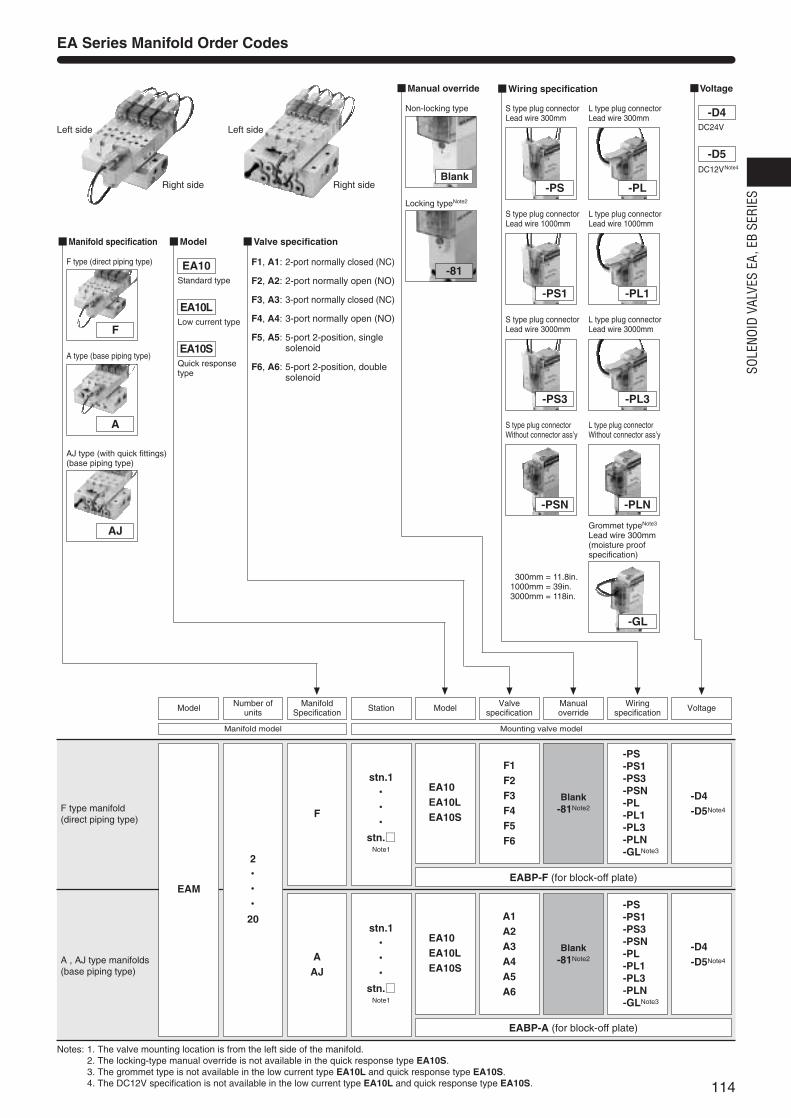
Locking typeNote2
Left side
Right side Right side
Left side
114
SOLE
NOID
VAL
VES
EA, E
B SE
RIES
Notes: 1. The valve mounting location is from the left side of the manifold.2. The locking-type manual override is not available in the quick response type EA10S.3. The grommet type is not available in the low current type EA10L and quick response type EA10S.4. The DC12V specification is not available in the low current type EA10L and quick response type EA10S.
F type manifold(direct piping type)
stn.1・・・・・・
stn.Note1
EA10EA10LEA10S
EABP-F (for block-off plate)
EABP-A (for block-off plate)
EAM
F1F2F3F4F5F6
Blank-81Note2
-D4-D5Note4
-PS-PS1-PS3-PSN-PL-PL1-PL3-PLN-GLNote3
A , AJ type manifolds(base piping type)
EA10EA10LEA10S
stn.1・・・・・・
stn.Note1
2・・・・・・20
F
AAJ
A1A2A3A4A5A6
Blank-81Note2
-D4-D5Note4
-PS-PS1-PS3-PSN-PL-PL1-PL3-PLN-GLNote3
Manual override
Blank
-81
Non-locking type
Manifold specification
F
A
F type (direct piping type)
A type (base piping type)
AJ
AJ type (with quick fittings)(base piping type)
VoltageWiring specification
-GL
Grommet typeNote3
Lead wire 300mm(moisture proofspecification)
-PS
S type plug connectorLead wire 300mm
-PS1
S type plug connectorLead wire 1000mm
-PS3
S type plug connector Lead wire 3000mm
-PSN
S type plug connectorWithout connector ass’y
-PL
L type plug connectorLead wire 300mm
-PL1
L type plug connectorLead wire 1000mm
-PL3
L type plug connector Lead wire 3000mm
-PLN
L type plug connectorWithout connector ass’y
-D4DC24V
-D5DC12VNote4
Model Valve specification
F1, A1: 2-port normally closed (NC)
F2, A2: 2-port normally open (NO)
F3, A3: 3-port normally closed (NC)
F4, A4: 3-port normally open (NO)
F5, A5: 5-port 2-position, singlesolenoid
F6, A6: 5-port 2-position, doublesolenoid
EA10
EA10L
EA10S
EA Series Manifold Order Codes
Station Valvespecification
ManualoverrideModel VoltageModel Number of
unitsManifold
SpecificationWiring
specification
Mounting valve modelManifold model
Standard type
Low current type
Quick response type
1300mm = 11.8in.1000mm = 39in.3000mm = 118in.
115
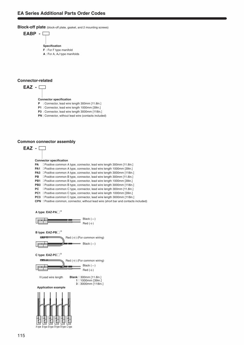
EABP -
SpecificationF : For F type manifoldA : For A, AJ type manifolds
EAZ - Connector-related
EA Series Additional Parts Order Codes
Block-off plate (block-off plate, gasket, and 2 mounting screws)
Connector specificationP : Connector, lead wire length 300mm [11.8in.]P1 : Connector, lead wire length 1000mm [39in.]P3 : Connector, lead wire length 3000mm [118in.]PN : Connector, without lead wire (contacts included)
EAZ - Common connector assembly
Connector specificationPA :Positive common A type, connector, lead wire length 300mm [11.8in.]PA1 :Positive common A type, connector, lead wire length 1000mm [39in.]PA3 :Positive common A type, connector, lead wire length 3000mm [118in.]PB :Positive common B type, connector, lead wire length 300mm [11.8in.]PB1 :Positive common B type, connector, lead wire length 1000mm [39in.]PB3 :Positive common B type, connector, lead wire length 3000mm [118in.]PC :Positive common C type, connector, lead wire length 300mm [11.8in.]PC1 :Positive common C type, connector, lead wire length 1000mm [39in.]PC3 :Positive common C type, connector, lead wire length 3000mm [118in.]CPN:Positive common, connector, without lead wire (short bar and contacts included)
Red (+) (For common wiring)
Black (-)
Red (+)
Black (-)
Red (+)
Red (+) (For common wiring)
Black (-)
※Lead wire length 1:1000mm [39in.] 3:3000mm [118in.]
A type B type B type B type B type C type
Application example
A type: EAZ-PA※
B type: EAZ-PB※
※C type: EAZ-PC
Blank:300mm [11.8in.]
116
SOLE
NOID
VAL
VES
EA, E
B SE
RIES
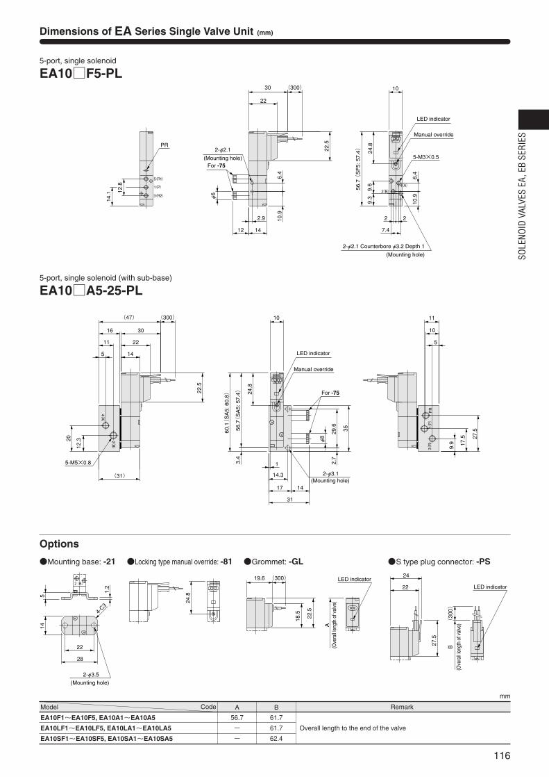
Remark
mm
EA10F1~EA10F5, EA10A1~EA10A5
EA10LF1~EA10LF5, EA10LA1~EA10LA5
EA10SF1~EA10SF5, EA10SA1~EA10SA5
56.7
-
-
61.7
61.7
62.4
Overall length to the end of the valve
Model Code A B
Dimensions of EA Series Single Valve Unit (mm)
24.8
2-φ3.5
4-C3
14
28
22
5
1.2
2(B)
(Mounting hole)
Locking type manual override: -81
A
18.5
22.5
(300)19.6
G
LED indicator
(Ove
rall l
engt
h of
val
ve)
Grommet: -GL
(300)
B27.5
22
24
LED indicator
(Ove
rall l
engt
h of
val
ve)
S type plug connector: -PSMounting base: -21
5-port, single solenoid
EA10F5-PL
φ6
12 14
2.9
22.5
22
(300)
24.8
For -75
6.4
10.9
2-φ2.1(Mounting hole)
9.6
56.7
(S
F5:
57.
4)
9.3
10
6.4
5-M3×0.5
10.9
7.4
2 2
30
4(A)
2(B)
5(R1)
1(P)
3(R2)
12.8
14.1
PR
Manual override
LED indicator
2-φ2.1 Counterbore φ3.2 Depth 1
(Mounting hole)
5-port, single solenoid (with sub-base)
EA10A5-25-PL
3.4
2(B)
4(A)
PR
1(P)
3(R)
56.7(
SA
5: 5
7.4)22.5
(300)(47)
30
22
14
16
14
10
31
17
1
14.3
φ8
60.1(
SA
5: 6
0.8)
24.8
11
10
5
(31)
2.7
29.6 35
5-M5×0.8
12.320
5
11
9.9
27.5
17.5
2-φ3.1
For -75
LED indicator
Manual override
(Mounting hole)
Options
117
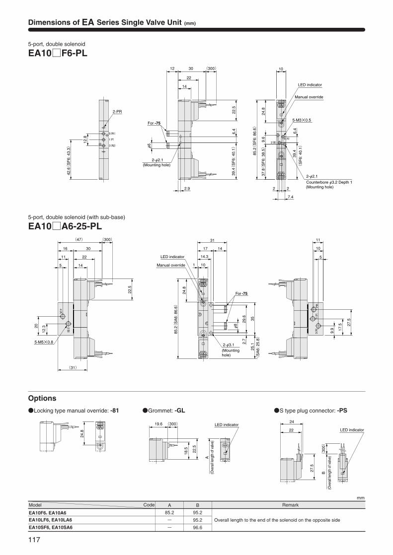
Dimensions of EA Series Single Valve Unit (mm)
mm
5-port, double solenoid (with sub-base)
EA10A6-25-PL
(31)
2(B)
4(A)
PR
1(P)
3(R)
31
1417
14.3
1145
(300)(47)
30
22
16
11
22.5
24.8
φ8
11
10
5
9.9
27.5
17.5
2.7
29.6
35
85.2(
SA
6: 8
6.6)
10
12.320
5-M5×0.8
25.1
(S
A6:
25.
8)
2-φ3.1(Mountinghole)
Manual override
For -75
LED indicator
5-port, double solenoid
EA10F6-PL
39.4
(S
F6:
40.
1)
37.8(
SF
6: 3
8.5)
39.4(
SF
6: 4
0.1)
42.6(
SF
6: 4
3.3)
12
5-M3×0.5
22
14
(300)30
22.5
6.4
24.8
6.4
9.6
12.8
φ6
10
85.2(
SF
6: 8
6.6)
2-φ2.1
3(R2)
1(P)
5(R1)
4(A)2(B)
2.9 22
7.4
2-PR
Manual override
LED indicator
For -75
(Mounting hole)
2-φ2.1
Counterbore φ3.2 Depth 1(Mounting hole)
24.8
Locking type manual override: -81
A
18.5
22.5
(300)19.6 LED indicator
(Ove
rall l
engt
h of
val
ve)
Grommet: -GL
(300)
B27.5
22
24
LED indicator
(Ove
rall l
engt
h of
val
ve)
S type plug connector: -PS
Remark
mm
EA10F6, EA10A6
EA10LF6, EA10LA6
EA10SF6, EA10SA6
85.2
-
-
95.2
95.2
96.6
Overall length to the end of the solenoid on the opposite side
Model Code A B
Options
Unit dimensions
Unit dimensionsNumber of units
118
SOLE
NOID
VAL
VES
EA, E
B SE
RIES
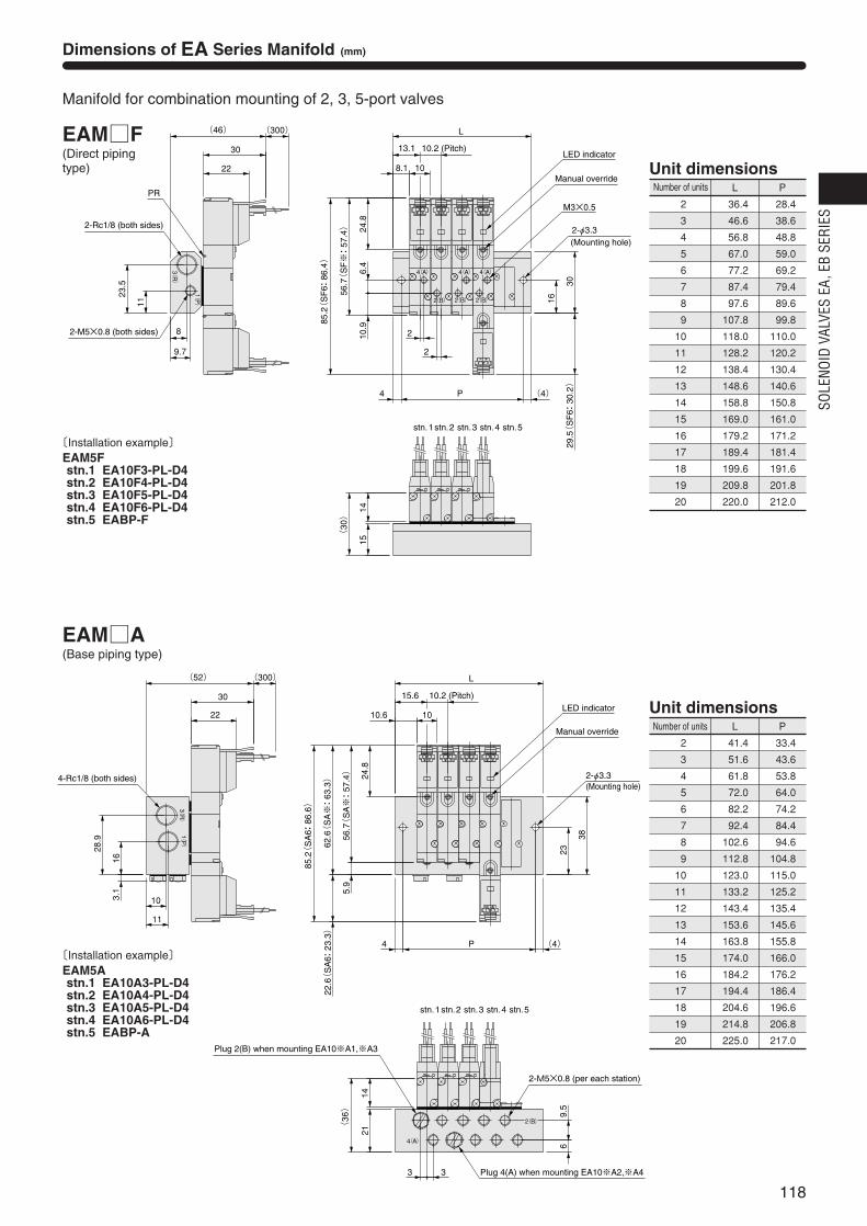
Dimensions of EA Series Manifold (mm)
Manifold for combination mounting of 2, 3, 5-port valves
EAMF(Direct piping type)
EAMA(Base piping type)
L P
36.4
46.6
56.8
67.0
77.2
87.4
97.6
107.8
118.0
128.2
138.4
148.6
158.8
169.0
179.2
189.4
199.6
209.8
220.0
28.4
38.6
48.8
59.0
69.2
79.4
89.6
99.8
110.0
120.2
130.4
140.6
150.8
161.0
171.2
181.4
191.6
201.8
212.0
2
3
4
5
6
7
8
9
10
11
12
13
14
15
16
17
18
19
20
Number of units L P
41.4
51.6
61.8
72.0
82.2
92.4
102.6
112.8
123.0
133.2
143.4
153.6
163.8
174.0
184.2
194.4
204.6
214.8
225.0
33.4
43.6
53.8
64.0
74.2
84.4
94.6
104.8
115.0
125.2
135.4
145.6
155.8
166.0
176.2
186.4
196.6
206.8
217.0
2
3
4
5
6
7
8
9
10
11
12
13
14
15
16
17
18
19
20
stn.1stn.2 stn.3 stn.4 stn.5
M3×0.5
9.7
8
2-φ3.3
(300)23.5
2
2
(4)P4
(30)
1415
29.5(
SF
6: 3
0.2)
24.8
6.4
10.9
85.2(
SF
6: 8
6.4)
56.7(
SF※: 5
7.4)
30
16
L
13.1
108.1
11(46)
30
22
1(P)
3(R)
2(B)
4(A)
2(B)2(B)
4(A)4(A)
PR
LED indicator
Manual override
(Mounting hole)
2-M5×0.8 (both sides)
10.2 (Pitch)
2-Rc1/8 (both sides)
5.9
62.6(
SA※: 6
3.3)
(36)
14
(52)
30
22
24.8
(4)P4
22.6(
SA
6: 2
3.3)
2-φ3.3(Mounting hole)
15.6
1010.6
21
9.5
6
L
38
23
85.2(
SA
6: 8
6.6)
56.7(
SA※: 5
7.4)
3.1
11
10
28.9
16
33
(300)1(P)
3(R)
4(A)
2(B)
stn.1stn.2 stn.3 stn.4 stn.5
LED indicator
Manual override
10.2 (Pitch)
4-Rc1/8 (both sides)
2-M5×0.8 (per each station)
Plug 2(B) when mounting EA10※A1,※A3
Plug 4(A) when mounting EA10※A2,※A4
〔Installation example〕EAM5Fstn.1 EA10F3-PL-D4stn.2 EA10F4-PL-D4stn.3 EA10F5-PL-D4stn.4 EA10F6-PL-D4stn.5 EABP-F
〔Installation example〕EAM5Astn.1 EA10A3-PL-D4stn.2 EA10A4-PL-D4stn.3 EA10A5-PL-D4stn.4 EA10A6-PL-D4stn.5 EABP-A
Unit dimensions
119
4-φ3.3
19.5
2.5
(38)
1423
(4)P4
L
15.6
1010.6
46
2411
67
85.2(
SA
6: 8
6.6)
14.6(
SA
6: 1
5.3)
70.6(
SA※: 7
1.3)
24.8
56.7(
SA※: 5
7.4)
13.9
38.5
24
13
11
22
(300)(54)
30
333(R)
1(P)
4(A)
2(B)
Plug 2(B) when mounting EA10※A1,※A3
Plug 4(A) when mounting EA10※A2,※A4
Quick fitting for 2-φ4
(per each station)
LED indicator
Manual override
(Mounting hole)
10.2 (Pitch)
4-Rc1/8 (both sides)
stn.1stn.2 stn.3 stn.4 stn.5
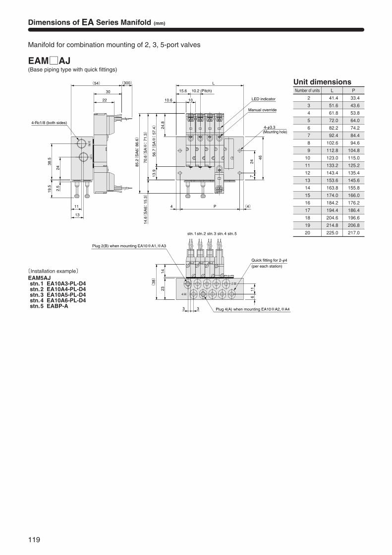
Dimensions of EA Series Manifold (mm)
Manifold for combination mounting of 2, 3, 5-port valves
EAMAJ(Base piping type with quick fittings)
Number of units L P
41.4
51.6
61.8
72.0
82.2
92.4
102.6
112.8
123.0
133.2
143.4
153.6
163.8
174.0
184.2
194.4
204.6
214.8
225.0
33.4
43.6
53.8
64.0
74.2
84.4
94.6
104.8
115.0
125.2
135.4
145.6
155.8
166.0
176.2
186.4
196.6
206.8
217.0
2
3
4
5
6
7
8
9
10
11
12
13
14
15
16
17
18
19
20
〔Installation example〕EAM5AJstn.1 EA10A3-PL-D4stn.2 EA10A4-PL-D4stn.3 EA10A5-PL-D4stn.4 EA10A6-PL-D4stn.5 EABP-A
EB
120
SOLE
NOID
VAL
VES
EA, E
B SE
RIES
Solenoid ValvesEB Series
121
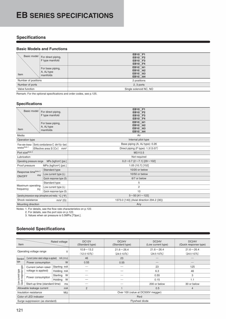
Specifications
Basic Models and Functions
Basic model
Item
Number of positions
Number of ports
Valve function
EB10F1EB10F2EB10F3EB10F4EB10A1EB10A2EB10A3EB10A42 positions
Remark: For the optional specifications and order codes, see p.125.
2, 3 ports
Single solenoid NC, NO
For direct piping, F type manifold
For base piping, A, AJ typemanifolds
Air
Internal pilot type
Not required
0.2~0.7 2~7.1 [29~102]
1.05 10.7 [152]
5
2
5~50 [41~122]
Any
Specifications
Notes: 1. For details, see the flow rate characteristics on p.122.2. For details, see the port size on p.122.3. Values when air pressure is 0.5MPa [73psi.].
Solenoid Specifications
Rated voltageItem
10.8~13.2
(12±10%)
46
0.55
―
―
―
―
―
2
21.6~26.4
(24±10%)
23
0.55
―
―
―
―
―
1Over 100 (value at DC500V megger)
Red
Flywheel diode
21.6~26.4
(24±10%)
―
―
23
6.3
0.55
0.15
200 or below
0.5
21.6~26.4
(24±10%)
―
―
125
46
3
1.1
30 or below
4
10/20 or below
10/50 or below
6/7 or below
10
1373.0 140 (Axial direction 294.2 30)
Base piping (A, AJ type): 0.26
Direct piping (F type): 1.3〔0.07〕
M3×0.5
Basic model
Item
For direct piping, F type manifold
For base piping, A, AJ typemanifolds
EB10F1EB10F2EB10F3EB10F4EB10A1EB10A2EB10A3EB10A4
EB SERIES SPECIFICATIONS
Media
Operation type
Port sizeNote 2
Lubrication
Operating pressure range MPa kgf/cm2 [psi.]
Proof pressure MPa kgf/cm2 [psi.]
Response timeNote 3
ON/OFF
Operating temperature range (atmosphere and media)
Shock resistance
Mounting direction
Flow rate charac-teristicsNote 1
Sonic conductance C dm3/(s・bar)
Effective area S〔Cv〕 mm2
Standard type
Low current type (L)
Quick response type (S)
Standard type
Low current type (L)
Quick response type (S)
°C [°F]
m/s2 G
Maximum operatingfrequency Hz
ms
Low
curre
ntty
peQ
uick
resp
onse
type
Standardtype
Operating voltage range
Current (when rated voltage is applied)
Power consumption
Current (when ratedvoltage is applied)
Power consumption
Start-up time (standard time)
Allowable leakage current
Insulation resistance
Color of LED indicator
Surge suppression (as standard)
V
mA (r.m.s)
W
Starting mA
Holding mA
Starting W
Holding W
ms
mA
MΩ
DC24V(Low current type)
DC24V(Quick response type)
DC12V(Standard type)
DC24V(Standard type)
122
SOLE
NOID
VAL
VES
EA, E
B SE
RIES
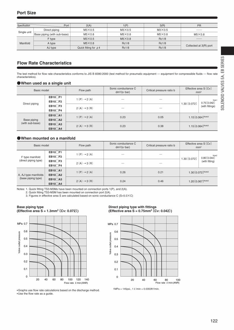
Port Size
Direct piping
Base piping (with sub-base)
F type
A type
AJ type
Single unit
Manifold
2(A)
M3×0.5
M5×0.8
M3×0.5
M5×0.8
Quick fitting for φ4
1(P)
M3×0.5
M5×0.8
M5×0.8
Rc1/8
Rc1/8
3(R)
M3×0.5
M5×0.8
Rc1/8
Rc1/8
Rc1/8
PR
M5×0.8
Collected at 3(R) port
Specification Port
EB10F1
EB10F2
EB10F3
EB10F4
EB10A1
EB10A2
EB10A3
EB10A4
Direct piping
Base piping(with sub-base)
1.30〔0.072〕 0.75〔0.042〕(with fittings)
1(P)→2(A)
2(A)→3(R)
1(P)→2(A)
2(A)→3(R)
―
―
0.23
0.23
―
―
0.05
0.38
1.15〔0.064〕Note3
1.15〔0.064〕Note3
When used as a single unit
Base piping type (Effective area S = 1.3mm2〔Cv: 0.072〕)
Direct piping type with fittings (Effective area S = 0.75mm2〔Cv: 0.042〕)
The test method for flow rate characteristics conforms to JIS B 8390:2000 (test method for pneumatic equipment — equipment for compressible fluids — flow ratecharacteristics).
Notes: 1. Quick fitting TS3-M3Ms have been mounted on connection ports 1(P), and 2(A).2. Quick fitting TS3-M3M has been mounted on connection port 2(A).3. Figures in effective area S are calculated based on sonic conductance C (S=5.0×C)
Flow Rate Characteristics
Basic model Flow path Critical pressure ratio bEffective area S〔Cv〕
mm2
Sonic conductance Cdm3/(s・bar)
EB10F1
EB10F2
EB10F3
EB10F4
EB10A1
EB10A2
EB10A3
EB10A4
F type manifold(direct piping type)
A, AJ type manifolds(base piping type)
1.30〔0.072〕 0.80〔0.044〕(with fitting)
1(P)→2(A)
2(A)→3(R)
1(P)→2(A)
2(A)→3(R)
―
―
0.26
0.24
―
―
0.21
0.46
1.30〔0.072〕Note3
1.20〔0.067〕Note3
When mounted on a manifold
Basic model Flow path Critical pressure ratio bEffective area S〔Cv〕
mm2
Sonic conductance Cdm3/(s・bar)
020 40 60 80 100 120 140 20 40 60 80 100
0.2
0.4
0.6
0.1
0.3
0.5
MPa 0.7
0
0.2
0.4
0.6
0.1
0.3
0.5
MPa 0.7
Flow rate R/min(ANR) Flow rate R/min(ANR)
Val
ve o
utle
t pre
ssur
e
Val
ve o
utle
t pre
ssur
e
Graphs use flow rate calculations based on the discharge method. Use the flow rate as a guide.
1MPa = 145psi., 1R/min = 0.0353ft.3/min.
Note1
Note2
123
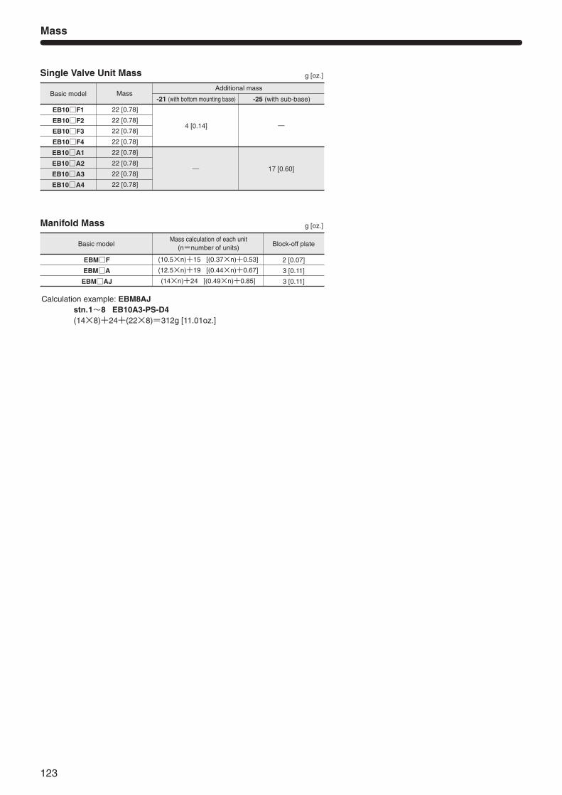
Single Valve Unit Mass
Mass
g [oz.]
Basic model
EB10F1
EB10F2
EB10F3
EB10F4
EB10A1
EB10A2
EB10A3
EB10A4
Mass
22 [0.78]
22 [0.78]
22 [0.78]
22 [0.78]
22 [0.78]
22 [0.78]
22 [0.78]
22 [0.78]
-21 (with bottom mounting base)
4 [0.14]
―
Additional mass
-25 (with sub-base)
―
17 [0.60]
Manifold Mass g [oz.]
Basic model
EBMF
EBMA
EBMAJ
Mass calculation of each unit(n=number of units)
(10.5×n)+15 [(0.37×n)+0.53]
(12.5×n)+19 [(0.44×n)+0.67]
(14×n)+24 [(0.49×n)+0.85]
Block-off plate
2 [0.07]
3 [0.11]
3 [0.11]
Calculation example: EBM8AJstn.1~8 EB10A3-PS-D4(14×8)+24+(22×8)=312g [11.01oz.]
124
SOLE
NOID
VAL
VES
EA, E
B SE
RIES
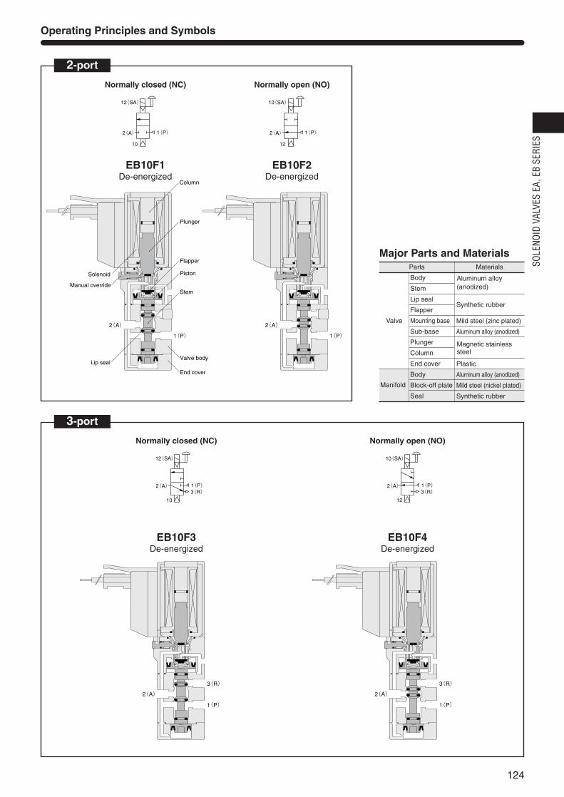
Operating Principles and Symbols
2-port
Normally closed (NC)
3-port
2(A)
12(SA)
10
1(P) 2(A)
10(SA)
12
1(P)
Normally open (NO)
2(A)
1(P)
Column
Plunger
Piston
Stem
Valve body
End cover
Lip seal
Flapper
Manual override
Solenoid
2(A)
1(P)
EB10F1De-energized
EB10F2De-energized
2(A)
12(SA)
10
3(R)1(P)
Normally closed (NC)
2(A)
1(P)
3(R)
2(A)
1(P)
3(R)
EB10F3De-energized
2(A)
10(SA)
12
3(R)1(P)
Normally open (NO)
EB10F4De-energized
Parts
Valve
Manifold
Materials
Body
Stem
Lip seal
Flapper
Mounting base
Sub-base
Plunger
Column
End cover
Body
Block-off plate
Seal
Synthetic rubber
Mild steel (zinc plated)
Aluminum alloy (anodized)
Plastic
Aluminum alloy (anodized)
Mild steel (nickel plated)
Synthetic rubber
Major Parts and Materials
Aluminum alloy(anodized)
Magnetic stainlesssteel
Without mounting base
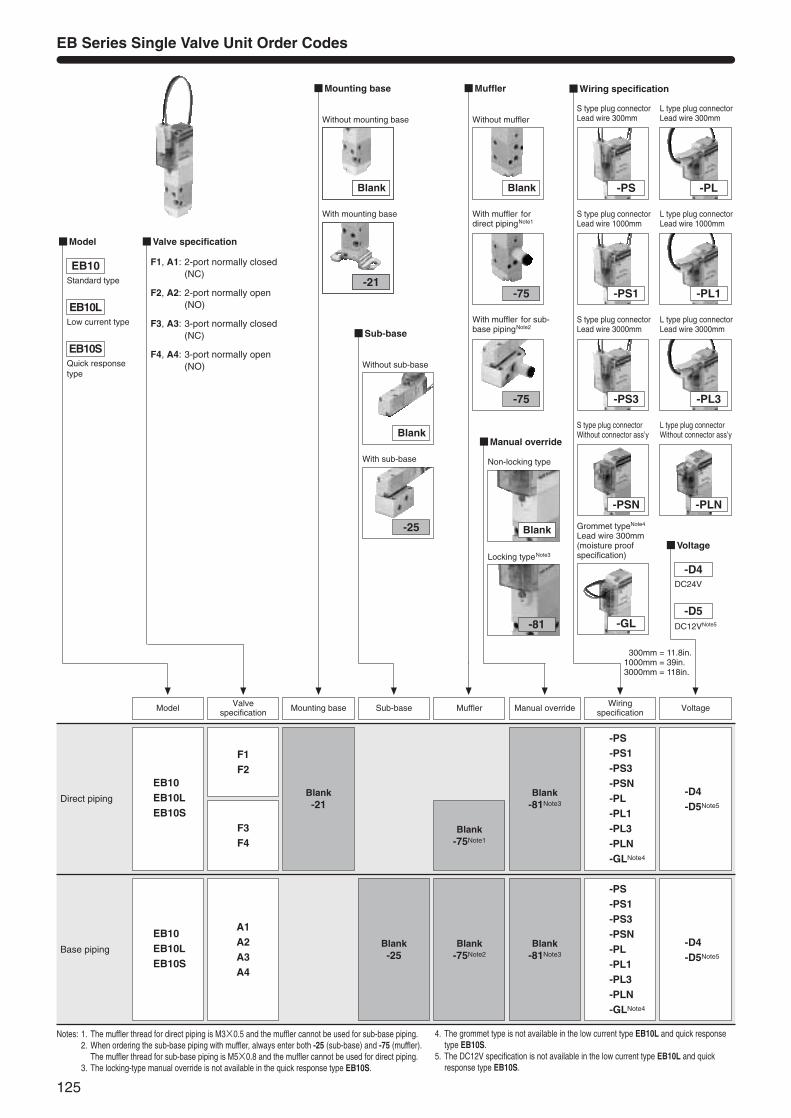
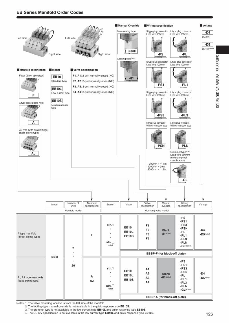
EB Series Single Valve Unit Order Codes
Notes: 1. The muffler thread for direct piping is M3×0.5 and the muffler cannot be used for sub-base piping.2. When ordering the sub-base piping with muffler, always enter both -25 (sub-base) and -75 (muffler).
The muffler thread for sub-base piping is M5×0.8 and the muffler cannot be used for direct piping.3. The locking-type manual override is not available in the quick response type EB10S.
4. The grommet type is not available in the low current type EB10L and quick responsetype EB10S.
5. The DC12V specification is not available in the low current type EB10L and quickresponse type EB10S.
Direct pipingBlank-21
F1F2
F3F4
EB10EB10LEB10S
Blank-75Note1
Blank-81Note3
-D4-D5Note5
Valve specification Mounting base MufflerSub-base
-PS-PS1-PS3-PSN-PL-PL1-PL3-PLN-GLNote4
Base pipingBlank-25
A1A2A3A4
EB10EB10LEB10S
Blank-75Note2
Blank-81Note3
-D4-D5Note5
-PS-PS1-PS3-PSN-PL-PL1-PL3-PLN-GLNote4
Wiringspecification VoltageModel Manual override
Sub-base
Blank
-25
Without sub-base
With sub-base
Manual override
Blank
-81
Non-locking type
Locking typeNote3
Voltage
Model Valve specification
F1, A1: 2-port normally closed(NC)
F2, A2: 2-port normally open(NO)
F3, A3: 3-port normally closed(NC)
F4, A4: 3-port normally open(NO)
Wiring specification
-GL
Grommet typeNote4
Lead wire 300mm(moisture proofspecification)
-PS
S type plug connectorLead wire 300mm
-PS1
S type plug connectorLead wire 1000mm
-PS3
S type plug connector Lead wire 3000mm
-PSN
S type plug connectorWithout connector ass’y
-PL
L type plug connectorLead wire 300mm
-PL1
L type plug connectorLead wire 1000mm
-PL3
L type plug connector Lead wire 3000mm
-PLN
L type plug connectorWithout connector ass’y
EB10
EB10L
EB10S
-D4DC24V
-D5DC12VNote5
With mounting base
Mounting base
Blank
-21
Muffler
Blank
-75
Without muffler
With muffler for sub-base pipingNote2
With muffler fordirect pipingNote1
-75
125
Standard type
Low current type
Quick responsetype
1300mm = 11.8in.1000mm = 39in.3000mm = 118in.
126
SOLE
NOID
VAL
VES
EA, E
B SE
RIES
Notes: 1. The valve mounting location is from the left side of the manifold.2. The locking-type manual override is not available in the quick response type EB10S.3. The grommet type is not available in the low current type EB10L and quick response type EB10S.4. The DC12V specification is not available in the low current type EB10L and quick response type EB10S.
F type manifold(direct piping type)
stn.1・・・・・・
stn.Note1
EB10EB10LEB10S
EBBP-F (for block-off plate)
EBBP-A (for block-off plate)
EBM
F1F2F3F4
Blank-81Note2
-D4-D5Note4
-PS-PS1-PS3-PSN-PL-PL1-PL3-PLN-GLNote3
A , AJ type manifolds(base piping type)
EB10EB10LEB10S
stn.1・・・・・・
stn.Note1
2・・・・・・20
F
AAJ
A1A2A3A4
Blank-81Note2
-D4-D5Note4
-PS-PS1-PS3-PSN-PL-PL1-PL3-PLN-GLNote3
Manual Override
Blank
-81
Non-locking type
Locking typeNote2
Manifold specification
F
A
F type (direct piping type)
A type (base piping type)
AJ
AJ type (with quick fittings)(base piping type)
VoltageWiring specification
-GL
Grommet typeNote3
Lead wire 300mm(moisture proofspecification)
-PS
S type plug connectorLead wire 300mm
-PS1
S type plug connectorLead wire 1000mm
-PS3
S type plug connector Lead wire 3000mm
-PSN
S type plug connectorWithout connector ass’y
-PL
L type plug connectorLead wire 300mm
-PL1
L type plug connectorLead wire 1000mm
-PL3
L type plug connector Lead wire 3000mm
-PLN
L type plug connectorWithout connector ass’y
-D4DC24V
-D5DC12VNote4
Model Valve specification
F1, A1: 2-port normally closed (NC)
F2, A2: 2-port normally open (NO)
F3, A3: 3-port normally closed (NC)
F4, A4: 3-port normally open (NO)
EB10
EB10L
EB10S
EB Series Manifold Order Codes
Station Valvespecification
ManualoverrideModel VoltageModel Number of
unitsManifold
specificationWiring
specification
Mounting valve modelManifold model
Left side
Right side
Left side
Right side
Standard type
Low current type
Quick response type
1300mm = 11.8in.1000mm = 39in.3000mm = 118in.
127
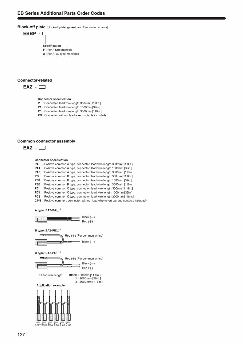
EBBP -
SpecificationF : For F type manifoldA : For A, AJ type manifolds
EAZ - Connector-related
EB Series Additional Parts Order Codes
Block-off plate (block-off plate, gasket, and 2 mounting screws)
Connector specificationP : Connector, lead wire length 300mm [11.8in.]P1 : Connector, lead wire length 1000mm [39in.]P3 : Connector, lead wire length 3000mm [118in.]PN : Connector, without lead wire (contacts included)
EAZ - Common connector assembly
Connector specificationPA :Positive common A type, connector, lead wire length 300mm [11.8in.]PA1 :Positive common A type, connector, lead wire length 1000mm [39in.]PA3 :Positive common A type, connector, lead wire length 3000mm [118in.]PB :Positive common B type, connector, lead wire length 300mm [11.8in.]PB1 :Positive common B type, connector, lead wire length 1000mm [39in.]PB3 :Positive common B type, connector, lead wire length 3000mm [118in.]PC :Positive common C type, connector, lead wire length 300mm [11.8in.]PC1 :Positive common C type, connector, lead wire length 1000mm [39in.]PC3 :Positive common C type, connector, lead wire length 3000mm [118in.]CPN:Positive common, connector, without lead wire (short bar and contacts included)
Red (+) (For common wiring)
Black (-)
Red (+)
Black (-)
Red (+)
Red (+) (For common wiring)
Black (-)
※Lead wire length 1:1000mm [39in.] 3:3000mm [118in.]
A type B type B type B type B type C type
Application example
A type: EAZ-PA※
B type: EAZ-PB※
※C type: EAZ-PC
Blank:300mm [11.8in.]
128
SOLE
NOID
VAL
VES
EA, E
B SE
RIES
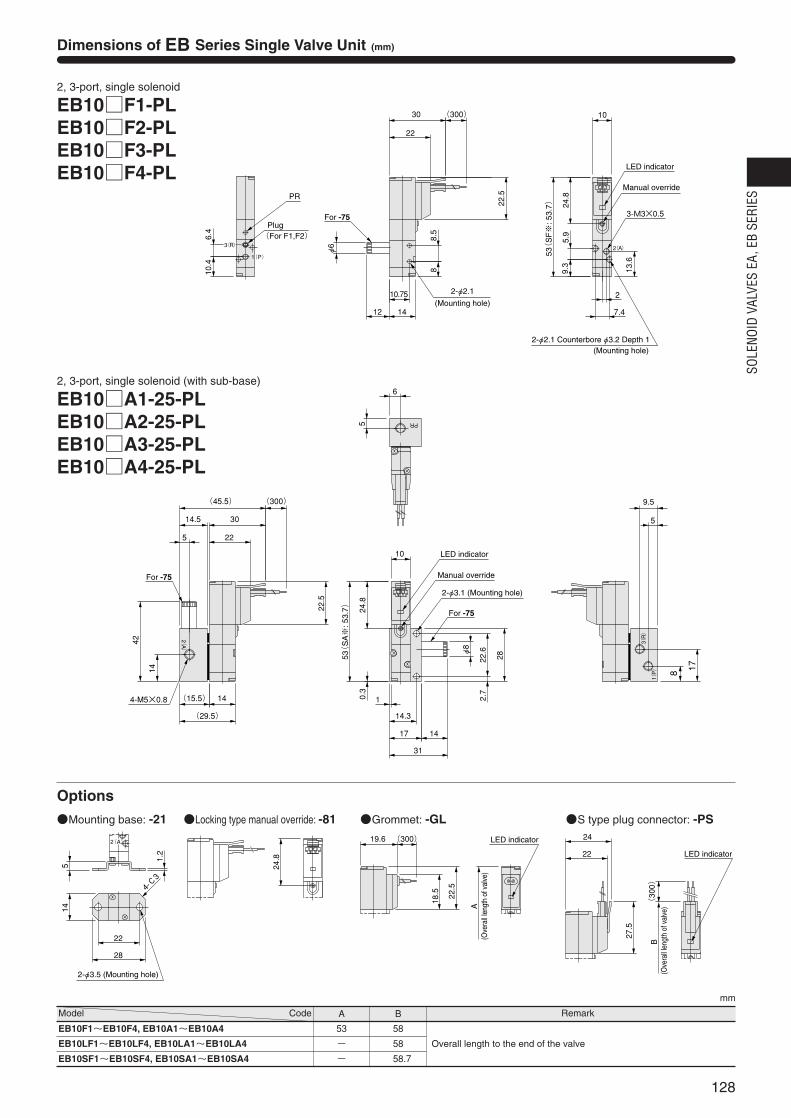
Dimensions of EB Series Single Valve Unit (mm)
2, 3-port, single solenoid
EB10F1-PLEB10F2-PLEB10F3-PLEB10F4-PL
22.5
22
14
10.75
24.8
2(A)3(R)
1(P)
10.4
6.4
PR
10
53(
SF※
: 53.
7)
9.3
5.9
2
7.4
13.6
3-M3×0.5
88.5
(300)30
12
φ6
Plug(For F1,F2)
Manual override
LED indicator
2-φ2.1 Counterbore φ3.2 Depth 1
2-φ2.1
(Mounting hole)
For -75
(Mounting hole)
2, 3-port, single solenoid (with sub-base)
EB10A1-25-PLEB10A2-25-PLEB10A3-25-PLEB10A4-25-PL
22.5
0.3
14.5
(15.5)
42
24.8
(29.5)
14
(300)(45.5)
30
22
31
1417
14.3
1
φ8
9.5
5
1(P)
3(R)
2(A)
8
2.7
22.6
2853(
SA※
: 53.
7)
10
4-M5×0.8
14
5
17
6
5 PR
For -75
LED indicator
Manual override
2-φ3.1 (Mounting hole)
For -75
24.8
2(A)
22
28
4-C3
5
1.2
14
2-φ3.5 (Mounting hole)
Locking type manual override: -81
19.6 (300)
22.5
18.5
A(O
vera
ll len
gth
of v
alve
)
LED indicator
Grommet: -GL
22
27.5
B(300)
24
LED indicator
(Ove
rall l
engt
h of
val
ve)
S type plug connector: -PSMounting base: -21
mm
Remark
EB10F1~EB10F4, EB10A1~EB10A4
EB10LF1~EB10LF4, EB10LA1~EB10LA4
EB10SF1~EB10SF4, EB10SA1~EB10SA4
53
-
-
58
58
58.7
Overall length to the end of the valve
Model Code A B
Options
129
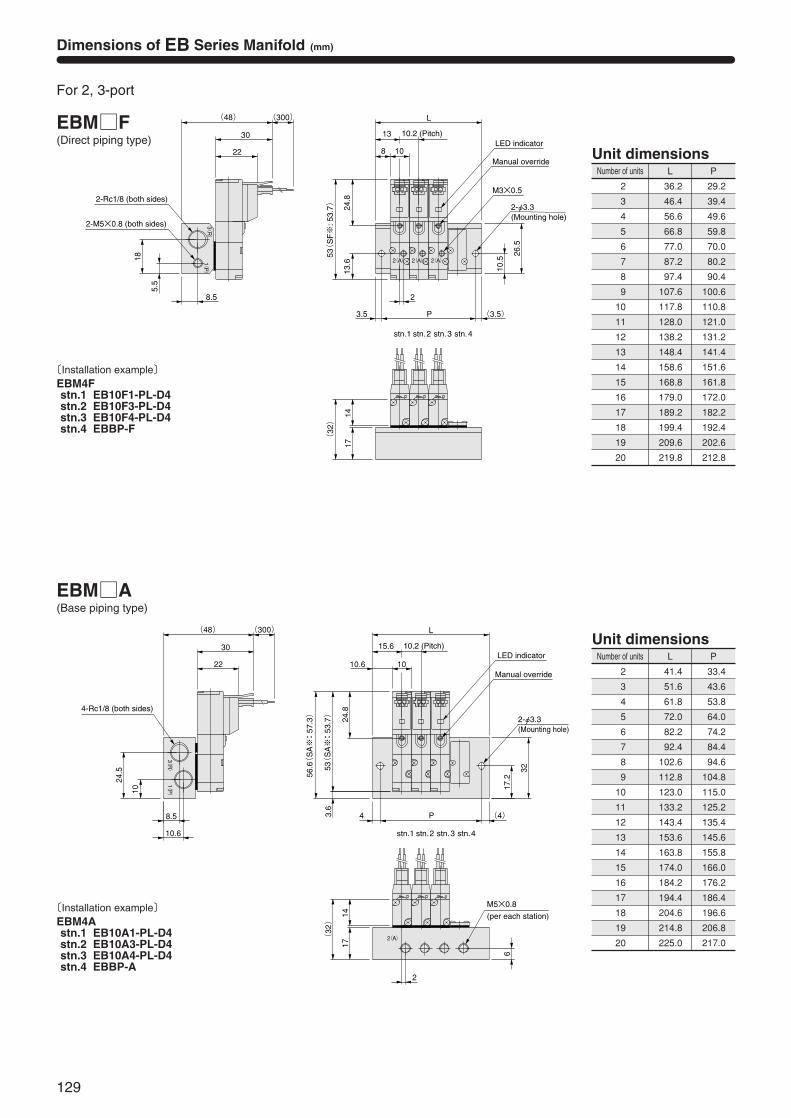
Dimensions of EB Series Manifold (mm)
For 2, 3-port
EBMF(Direct piping type)
Number of units L P
36.2
46.4
56.6
66.8
77.0
87.2
97.4
107.6
117.8
128.0
138.2
148.4
158.6
168.8
179.0
189.2
199.4
209.6
219.8
29.2
39.4
49.6
59.8
70.0
80.2
90.4
100.6
110.8
121.0
131.2
141.4
151.6
161.8
172.0
182.2
192.4
202.6
212.8
Unit dimensions
2
3
4
5
6
7
8
9
10
11
12
13
14
15
16
17
18
19
20
stn.4stn.3stn.2stn.1
M3×0.5
18
5.5
8.5
(300)(48)
30
22
(32)
1417
2
13
2(A)
L
108
(3.5)P3.5
53(
SF※
: 53.
7) 24.8
26.5
10.5
13.6 2(A)2(A)1(
P)3(R)
LED indicator
Manual override
2-Rc1/8 (both sides)
2-M5×0.8 (both sides)
10.2 (Pitch)
2-φ3.3(Mounting hole)
〔Installation example〕EBM4Fstn.1 EB10F1-PL-D4stn.2 EB10F3-PL-D4stn.3 EB10F4-PL-D4stn.4 EBBP-F
EBMA(Base piping type)
Number of units L P
41.4
51.6
61.8
72.0
82.2
92.4
102.6
112.8
123.0
133.2
143.4
153.6
163.8
174.0
184.2
194.4
204.6
214.8
225.0
33.4
43.6
53.8
64.0
74.2
84.4
94.6
104.8
115.0
125.2
135.4
145.6
155.8
166.0
176.2
186.4
196.6
206.8
217.0
Unit dimensions
2
3
4
5
6
7
8
9
10
11
12
13
14
15
16
17
18
19
20
2
6
(32)
1417
(300)(48)
30
22
10.6
8.5
24.5
10
(4)P4
32
17.256
.6(S
A※: 5
7.3)
3.6
53(
SA※: 5
3.7) 24.8
L
15.6
1010.6
1(P)
3(R)
2(A)
stn.4stn.3stn.2stn.1
M5×0.8
(per each station)
LED indicator
Manual override
4-Rc1/8 (both sides)2-φ3.3 (Mounting hole)
10.2 (Pitch)
〔Installation example〕EBM4Astn.1 EB10A1-PL-D4stn.2 EB10A3-PL-D4stn.3 EB10A4-PL-D4stn.4 EBBP-A
130
SOLE
NOID
VAL
VES
EA, E
B SE
RIES
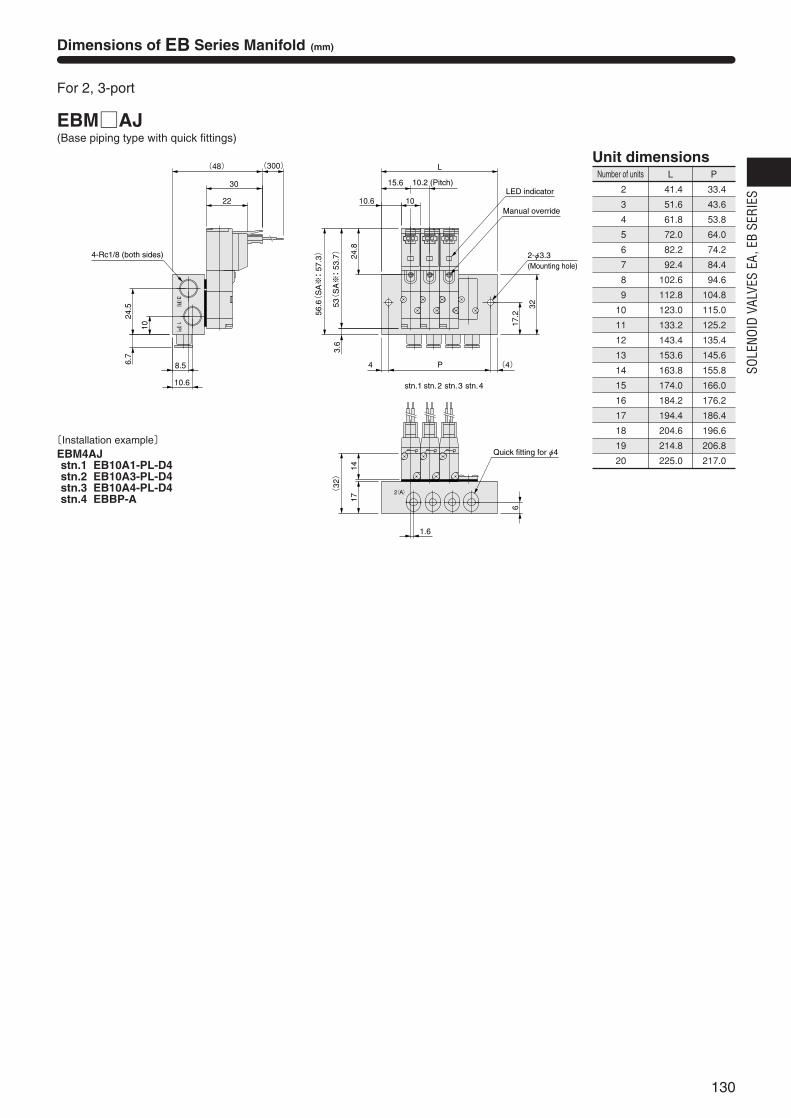
Dimensions of EB Series Manifold (mm)
For 2, 3-port
EBMAJ(Base piping type with quick fittings)
Number of units L P
41.4
51.6
61.8
72.0
82.2
92.4
102.6
112.8
123.0
133.2
143.4
153.6
163.8
174.0
184.2
194.4
204.6
214.8
225.0
33.4
43.6
53.8
64.0
74.2
84.4
94.6
104.8
115.0
125.2
135.4
145.6
155.8
166.0
176.2
186.4
196.6
206.8
217.0
Unit dimensions
2
3
4
5
6
7
8
9
10
11
12
13
14
15
16
17
18
19
20
6.7
24.5
10
10.6
8.5
(300)(48)
30
22
(32)
1417
6
32
17.2
(4)P4
56.6(
SA※: 5
7.3)
3.6
53(
SA※: 5
3.7) 24.8
L
1.6
15.6
1010.6
3(R)
1(P)
2(A)
Quick fitting for φ4
LED indicator
Manual override
4-Rc1/8 (both sides) 2-φ3.3(Mounting hole)
10.2 (Pitch)
stn.4stn.3stn.2stn.1
〔Installation example〕EBM4AJstn.1 EB10A1-PL-D4stn.2 EB10A3-PL-D4stn.3 EB10A4-PL-D4stn.4 EBBP-A

131
31
Do not use for the purposes listed below:1. Medical equipment related to maintenance or management
of human lives or bodies.2. Mechanical devices or equipment designed for the purpose
of moving or transporting people.3. Critical safety components in mechanical devices.This product has not been planned or designed for purposesthat require advanced stages of safety. It could cause injury tohuman life.
Do not use in locations with or near dangerous substancessuch as flammable or ignitable substances. This product isnot explosion-proof. It could ignite or burst into flames.
When attaching the product and workpiece, always ensurethat it is securely mounted in place. Dropping or falling theproduct or improper operation could result in injury.
Persons who use a pacemaker, etc., should keep a distanceof at least one meter [3.28ft.] away from the product. There isa possibility that the pacemaker will malfunction due to thestrong magnet built into the product.
Never attempt to remodel the product. It could result inabnormal operation leading to injury, electric shock, fire, etc.
Never attempt inappropriate disassembly, assembly or repairof the product’s basic construction, or of its performance orfunctions. It could result in injury, electric shock, fire, etc.
Do not splash water on the product. Spraying it with water,washing it, or using it underwater could result in malfunctionof the product leading to injury, electric shock, fire, etc.
While the product is in operation, avoid touching it with yourhands or otherwise approaching too close. In addition, do notmake any adjustments to the interior or to the attachedmechanisms (manual override, connecting and disconnectingof wiring connectors, adjustment of pressure switches, orrelease or connection of piping tubes or plugs) while inoperation. The actuator can move suddenly, possibly resultingin injury.
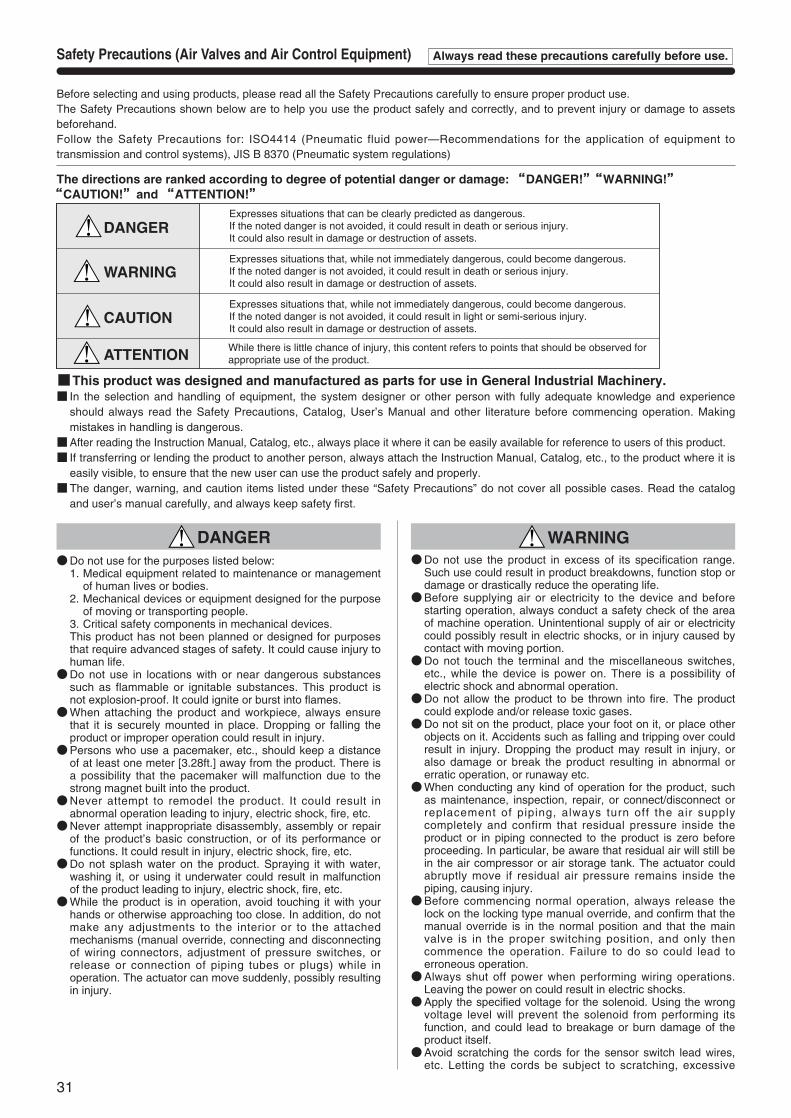
Before selecting and using products, please read all the Safety Precautions carefully to ensure proper product use.The Safety Precautions shown below are to help you use the product safely and correctly, and to prevent injury or damage to assetsbeforehand.Follow the Safety Precautions for: ISO4414 (Pneumatic fluid power—Recommendations for the application of equipment totransmission and control systems), JIS B 8370 (Pneumatic system regulations)
This product was designed and manufactured as parts for use in General Industrial Machinery. In the selection and handling of equipment, the system designer or other person with fully adequate knowledge and experience
should always read the Safety Precautions, Catalog, User’s Manual and other literature before commencing operation. Makingmistakes in handling is dangerous.
After reading the Instruction Manual, Catalog, etc., always place it where it can be easily available for reference to users of this product. If transferring or lending the product to another person, always attach the Instruction Manual, Catalog, etc., to the product where it is
easily visible, to ensure that the new user can use the product safely and properly.The danger, warning, and caution items listed under these “Safety Precautions” do not cover all possible cases. Read the catalog
and user’s manual carefully, and always keep safety first.
DANGERExpresses situations that can be clearly predicted as dangerous. If the noted danger is not avoided, it could result in death or serious injury. It could also result in damage or destruction of assets.
WARNINGExpresses situations that, while not immediately dangerous, could become dangerous. If the noted danger is not avoided, it could result in death or serious injury. It could also result in damage or destruction of assets.
CAUTIONExpresses situations that, while not immediately dangerous, could become dangerous. If the noted danger is not avoided, it could result in light or semi-serious injury. It could also result in damage or destruction of assets.
ATTENTION While there is little chance of injury, this content refers to points that should be observed forappropriate use of the product.
The directions are ranked according to degree of potential danger or damage: ““DANGER!””““WARNING!””““CAUTION!””and ““ATTENTION!””
Safety Precautions (Air Valves and Air Control Equipment) Always read these precautions carefully before use.
DANGER WARNINGDo not use the product in excess of its specification range.
Such use could result in product breakdowns, function stop ordamage or drastically reduce the operating life.
Before supplying air or electricity to the device and beforestarting operation, always conduct a safety check of the areaof machine operation. Unintentional supply of air or electricitycould possibly result in electric shocks, or in injury caused bycontact with moving portion.
Do not touch the terminal and the miscellaneous switches,etc., while the device is power on. There is a possibility ofelectric shock and abnormal operation.
Do not allow the product to be thrown into fire. The productcould explode and/or release toxic gases.
Do not sit on the product, place your foot on it, or place otherobjects on it. Accidents such as falling and tripping over couldresult in injury. Dropping the product may result in injury, oralso damage or break the product resulting in abnormal orerratic operation, or runaway etc.
When conducting any kind of operation for the product, suchas maintenance, inspection, repair, or connect/disconnect orreplacement of piping, always turn off the air supplycompletely and confirm that residual pressure inside theproduct or in piping connected to the product is zero beforeproceeding. In particular, be aware that residual air will still bein the air compressor or air storage tank. The actuator couldabruptly move if residual air pressure remains inside thepiping, causing injury.
Before commencing normal operation, always release thelock on the locking type manual override, and confirm that themanual override is in the normal position and that the mainvalve is in the proper switching position, and only thencommence the operation. Failure to do so could lead toerroneous operation.
Always shut off power when performing wiring operations.Leaving the power on could result in electric shocks.
Apply the specified voltage for the solenoid. Using the wrongvoltage level will prevent the solenoid from performing itsfunction, and could lead to breakage or burn damage of theproduct itself.
Avoid scratching the cords for the sensor switch lead wires,etc. Letting the cords be subject to scratching, excessive
32
bending, pulling, rolling up, or being placed under heavyobjects or squeezed between two objects, may result incurrent leaks or defective transmission that lead to fires,electric shocks, or abnormal operation.
Do not pull out the connectors while the power is ON. Also, donot put unnecessary stress on the connector. It could result inerroneous equipment operation that could lead to personalinjury, equipment breakdown, or electrical shocks, etc.
Always check the Catalog to ensure that the product wiringand piping is done correctly. Errors in wiring and piping couldlead to abnormal operation of the actuators, etc.
In the first operation after the equipment has been idle for 48hours or more, or has been in storage, there is a possibilitythat contacting parts have been sticked, result ing inequipment operation delays or sudden movements. For thesefirst operations, always run a test operation before use tocheck that operating performance is normal.
In low frequency use (more than 30 days between uses),there is a possibility that contact parts will stick, resulting inequipment operation delays or sudden movements that couldlead to personal injury. Run a test operation at least onceevery 30 days to confirm that movement is normal.
For double solenoid type (excluding the Tandem 3-portvalve), do not apply current through both solenoidssimultaneously. It is impossible in such a situation to maintainthe correct valve position, and the equipment may operate inan unintended direction, leading to the possibil i ty ofequipment breakdown or personal injury.
Do not use the solenoid valves or the wiring that controls them,near power lines where large electrical currents are flowing, orin locations subject to powerful magnetic fields or powersurges. Such application could lead to unintended operation.
The solenoid valve can generate surge voltage andelectromagnetic waves when the switch is turned off, affectingthe operations of surrounding equipment. Use solenoids withsurge suppression, or take countermeasures in the electricalcircuits for surges or electromagnetic waves.
Do not use where ozone may be generated, such as nearocean beaches or other places subject to direct sunlight ormercury lamps. Ozone can cause rubber parts to deteriorate,which can lead to degraded performance and functions, or toequipment stoppages and functional shutdown. (Excludesitems where measures against ozone have been taken.)
Do not use any media other than shown on the specifications.Use of non-specified media could lead to functional shutdownafter a short period, to sudden performance drops, or toshorter operating life.
If mounting the solenoid valve inside a control panel, or ifenergizing it for long periods, provide heat radiation measuresto ensure that temperatures surrounding the solenoid valvealways remain within the specified temperature range. Ifenergizing the unit for long periods, consult us.
After finishing wiring operations, always check to ensure thatno wiring connection errors exist before turning on the power.
Do not collect the exhaust lines for air cylinders, etc. with pilotexhaust lines for solenoid valves into the same piping, etc.Interference in the exhaust could result in erratic operation.
CAUTIONWhen mounting the product, leave room for adequate working
space around it. Failure to ensure adequate working spacewill make it more difficult to conduct daily inspections ormaintenance, which could eventually lead to systemshutdown or damage to the product.
For mounting or transport of heavy products, use a lift,supporting tool, or several people, to provide firm support,and proceed with due caution to ensure personal safety.
Do not bring floppy disks or magnetic media, etc., within onemeter [3.28ft.] of the product. There is the possibility that thedata on the floppy disks will be destroyed due to themagnetism of the magnet.
If leakage current is occurring in the control circuit, there is apossibility of the product performing an unintended operation.Take measures against current leaking in the control circuit,to ensure that the leakage current value does not exceed theallowed range in the product specifications.
Do not block the product’s breathing holes. Pressure changesoccur due to changes in volume during operation. Blockingthe breathing holes destroys the pressure balance, and couldcause failure of the intentioned operation, equipment damage,or personal injury.
Do not use the solenoid valve in locations subject to largeelectrical currents or magnetic fields. It could result in erraticoperation.
Oily materials from the compressor (excluding the oil-freecompressor) can cause drastic deterioration in productperformance, and even a functional shutdown. Always installa mist filter before pneumatic equipment to remove the oilycomponent.
The properties of the lubrication oil can change when used indry air where dew point temperatures is lower than –20degrees Celsius [–4°F]. It could result in degradedperformance or in functional shutdown.
Do not use the product in locations of direct sunlight(ultraviolet), in locations subject to dust, salt, or iron powder,in locations with humidity and high temperature, or in themedia and/or the ambient atmospheres that include organicsolvents, phosphoric ester type hydraulic oil, sulfur dioxide,chlorine gas, or acids, etc. These conditions could lead tofunctional shutdowns, sudden degraded performance, orshortened operating life in a brief period of time. For materialsused, see Major Parts and Materials.
ATTENTIONWhen considering the possibility of using this product in
situations or environments not specifically noted in theCatalog or User’s Manual, or in applications where safety isan important requirement, such as in an airplane facility,combustion equipment, leisure equipment, safety equipmentand other places where human life or assets may be greatlyaffected, take adequate safety precautions such asapplication with enough margins for ratings and performanceor fail-safe measures. Be sure to consult us with suchapplications.
Always check the catalog and other reference materials forproduct wiring and piping.
Install a muffler, etc. on the exhaust port. It is effective inreducing exhaust noise.
When handling the product, wear protective gloves, safetyglasses, safety boots, etc. to keep safety.
When the product can no longer be used, or is no longernecessary, dispose of it appropriately as industrial waste.
Pneumatic equipment can exhibit degraded performance andfunction over its operating l ife. Always conduct dailyinspections of the pneumatic equipment, and confirm that allrequisite system functions are satisfied, to prevent accidentsfrom happening.
Air leaks from the valve are not zero. For application of requiringholding pressure (including vacuum) inside the pressure vessel,consider adequate margin of capacity and holding time indesign of the system.
For inquiries about the product, consult your nearest Koganeisales office or Koganei overseas department. The address andtelephone number is shown on the back cover of this catalog.
OTHERSAlways observe the following items.
1. When using this product in pneumatic systems, always usegenuine KOGANEI parts or compatible parts (recom-mended parts).When conducting maintenance and repairs, always usegenuine KOGANEI parts or compatible parts (rec-ommended parts). Always observe the required methodsand procedure.
2. Do not attempt inappropriate disassembly or assembly ofthe product relating to basic construction, or i tsperformance or functions.
Koganei cannot be responsible if these items are not properlyobserved.
33
Insert the tube to connect as far as thetube stopper contacts the tubes. Pull thetube to confirm the connection.For tube removal, push the release ringforward parallel to the ring, and pull thetube out.
Tube installation and removal
Either nylon or urethane tubes can beused. Use tubes that are not scratched ontheir outer surface.The tube’s outer diameter toleranceshould be within ±0.1mm [±0.004in.] ofthe nominal dimension, and within 0.2mm[0.008in.] for the ellipticity (differencebetween long and short diameter).
Tubes
Caution: Do not excessively bend the tube nearfittings.
Subsonic speed flow when P1+0.1013<1.89 (P2+0.1013)
Q=226S ΔP (P2+0.1013)
Sonic speed flow when P1+0.1013≧1.89 (P2+0.1013)
Q=113S (P1+0.1013)
Q: Air flow rate〔R/min (ANR)〕S: Effective area〔mm2〕
ΔP: Pressure drop P1-P2〔MPa〕P1: Upstream pressure〔MPa〕P2: Downstream pressure〔MPa〕
※Corrections for variances in air temperatureMultiply the flow rate calculated in the formulaabove by the coefficients in the table below.
Since the 1(P) and exhaust ports are onboth ends of the manifold, piping directioncan be selected depending on theapplication (excluding some models).At shipping, plugs are temporari lyscrewed in ports at one end, but are notfirmly tightened. Regardless of which endpiping is connected, always remove theplugs, use sealing tape or apply othersealing agent, and securely tighten theplugs into the unused ports.
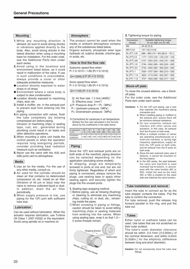
1. Sealing tape wrapping methodqBefore piping, use air blowing (flushing)
or cleaning to eliminate any machiningchips, cutting oil, or dust, etc., remain-ing inside the pipes.
wWhen screwing in piping or fittings,caution should be taken to avoid lettingmachining chips or sealing materialsfrom entering into the valves. Whenusing sealing tape, wrap it so that 1.5~2 screw threads remain.
Piping
Remain about 2 screw theads
Sealing tape
Wrapping direction
How to find the flow rate
Air temperature°C [°F]
Correctioncoefficient
–20[–4]
1.08
–10[14]
1.06
0[32]
1.04
10[50]
1.02
30[86]
0.98
40[104]
0.97
50[122]
0.95
60[140]
0.94
M3
M5×0.8
Rc (PT )1/8
Rc (PT)1/4
Rc (PT) 3/8
Rc (PT) 1/2
Rc (PT) 3/4
Rc (PT) 1
Rc (PT) 1 1/4
Rc (PT) 1 1/2
59 (6) [5.2]
157 (16) [13.9]
686~883 (70~90) [60.8~78.1]
1177~1373 (120~140) [104~122]
2157~2354 (220~240) [191~208]
2746~2942 (280~300) [243~260]
2746~2942 (280~300) [243~260]
3530~3727 (360~380) [313~330]
3923~4119 (400~420) [347~365]
4707~4903 (480~500) [417~434]
2. Tightening torque for piping
1. While any mounting direction isallowed, be sure to avoid strong shocksor vibrations applied directly to thebody. Also, avoid strong shocks in thelateral direction when using a mountingbase for installation. For the order code,see the Additional Parts item undereach series.
2. Avoid using in the locations andenvironment listed below, as it couldresult in malfunction of the valve. If usein such conditions is unavoidable,always provide a cover or otheradequate protective measures.
Location directly exposed to waterdrops or oil drops
Environment where a valve body issubject to dew condensation
Location directly exposed to machiningchips, dust, etc
3. Install a muffler, etc. in the exhaust portto prevent dust from entering into thepiping.
4.In piping connection with valves, flushthe tube completely (by blowingcompressed air) before piping.Intrusion of machining chips or sealingtape, rust, etc., generated duringplumbing could result in air leaks andother defective operations.
5. When mounting a valve unit inside thecontrol panels or when the operationrequires long energizing periods,consider providing heat radiationmeasure such as ventilation.
6. Never use the valve with the 4(A) and2(B) ports vent to atmosphere.
Mounting
Can be used without lubrication. When theactuator requires lubrication, use TurbineOil Class 1 (ISO VG32) or the equivalent.Avoid using spindle oil or machine oil.
Lubrication
1. Use air for the media. For the use ofany other media, consult us.
2. Air used for the cylinder should beclean air that contains no deterioratedcompressor oil, etc. Install an air filter(filtration of 40 µm or less) near thevalve to remove collected liquid or dust.In addit ion, drain the air f i l terperiodically.
3. When supply pressure is low, usepiping for the 1(P) port with sufficienttube size.
Media
The product cannot be used when themedia or ambient atmosphere containsany of the substances listed below.Organic solvents, phosphate ester typehydraulic oil, sulphur dioxide, chlorine gas,or acids, etc.
Atmosphere
To close the unused stations, use a block-off plate.For the order code, see the AdditionalParts item under each series.
Block-off plate
Cautions: 1. For the 1(P) port piping, use a sizethat matches the manifold’s pipingconnection port.
2. When installing piping or mufflers tothe exhaust port, ensure there willbe minimum exhaust resistance.
3. On rare occasions, exhaust caninterfere with other valves andactuators. In this case, let exhaustfrom the R ports on both ends.
4. When a multiple number of valvesare operating simultaneously on amulti-unit manifold, or during highfrequency applications, supply airfrom the 1(P) ports on both ends,and let exhaust from the R ports onboth ends.
5. Since the twin solenoid valve uses 2stations, it cannot be mounted onthe final station.
6. In the 025 series, the seal betweenthe valve and manifold is usedreversed top-to-bottom, in accord-ance with the valve function (NC orNO). Install the seal as the mark(NC or NO) is located on the valveside and matches the valve function.
General Precautions
Suitable tightening torque N・cm (kgf・cm) [in・lbf]
Connection thread