Embed Size (px)
Citation preview

CHAPTER 12
SOLID PROPELLANTS
In this chapter we describe several common solid rocket propellants, their principal categories, ingredients, hazards, manufacturing processes, and qual- ity control. We also discuss liners and insulators, propellants for igniters, tailoring of propellants, and propellants for gas generators. It is the second of four chapters dealing with solid propellant rocket motors.
Thermochemical analyses are needed to characterize the performance of a given propellant. The analysis methods are described in Chapter 5. Such ana- lyses provide theoretical values of average molecular weight, combustion tem- perature, average specific heat ratio, and the characteristic velocity; they are functions of the propellant composition and chamber pressure. A specific impulse can also be computed for a particular nozzle configuration.
The term solid propellant has several connotations, including: (1) the rub- bery or plastic-like mixture of oxidizer, fuel, and other ingredients that have been processed and constitute the finished grain; (2) the processed but uncured product; (3) a single ingredient, such as the fuel or the oxidizer. Acronyms and chemical symbols are used indiscriminately as abbreviations for propellant and ingredient names; only some of these will be used here.
12.1. CLASSIFICATION
Processed modern propellants can be classified in several ways, as described below. This classification is not rigorous or complete. Sometimes the same propellant will fit into two or more of the classifications.
474
12.1. CLASSIFICATION 4,75
1. Propellants are often tailored to and classified by specific applications, such as space launch booster propellants or tactical missile propellants; each has somewhat specific chemical ingredients, different burning rates, different physical properties, and different performance. Table 11-1 shows four kinds of rocket motor applications (each has somewhat dif- ferent propellants) and several gas generator applications. Propellants for rocket motors have hot (over 2400 K) gases and are used to produce thrust, but gas generator propellants have lower-temperature combustion gases (800 to 1200 K) and they are used to produce power, not thrust.
Historically, the early rocket motor propellants used to be grouped into two classes: double-base (DB*) propellants were used as the first production propellants, and then the development of polymers as binders made the composite propellants feasible.
2. Double-base (DB) propellants form a homogeneous propellant grain, usually a nitrocellulose (NC*), a solid ingredient which absorbs liquid nitroglycerine (NG) plus minor percentages of additives. Both the major ingredients are explosives and function as a combined fuel and oxidizer. Both extruded double-base (EDB) and cast double-base (CDB) propellant have found extensive applications, mostly in small tactical missiles of older design. By adding crystalline nitramines (HMX or RDX)* the performance and density can be improved; this is sometimes called cast-modified double-base propellant. A further improvement is to add an elastomeric binder (rubber-like, such as crosslinked polybutadiene), which improves the physical properties and allows more nitramine and thus improves the performance slightly. The resulting propellant is called elastomeric-modified cast double-base (EMCDB). These four classes of double base have nearly smokeless exhausts. Adding some solid ammo- nium perchlorate (AP) and aluminum (A1) increases the density and the specific impulse slightly, but the exhaust gas is smoky. The propellant is called composite-modified double-base propellant or CMDB.
3. Composite propellants form a heterogeneous propellant grain with the oxidizer crystals and a powdered fuel (usually aluminum) held together in a matrix of synthetic rubber (or plastic) binder, such as polybutadiene (HTPB)*. Composite propellants are cast from a mix of solid (AP crys- tals, A1 powder)* and liquid (HTPB, PPG)* ingredients. The propellant is hardened by crosslinking or curing the liquid binder polymer with a small amount of curing agent, and curing it in an oven, where it becomes hard and solid. In the past three decades the composite propellants have been the most commonly used class. They can be further subdivided:
(1) Conventional composite propellants usually contain between 60 and 72% ammonium perchlorate (AP) as crystalline oxidizer, up to 22%
*Acronyms, symbols, abbreviations, and chemical names of propellant ingredients are explained in Tables 12-6 and 12-7 in Section 12.4.

476 SOLID PROPELLANTS
aluminum powder (A1) as a metal fuel, and 8 to 16% of elastomeric binder (organic polymer) including its plasticizer.
(2) Modified composite propellant where an energetic nitramine (HMX or RDX) is added for obtaining a little more performance and also a somewhat higher density.
(3) Modified composite propellant where an energetic plasticizer such as nitroglycerine (used in double-base propellant) is added to give a little more performance. Sometimes HMX is also added.
(4) A high-energy composite solid propellant (with some aluminum), where the organic elastomeric binder and plasticizer are largely replaced by energetic materials (such as certain explosives) and where some of the AP is replaced by HMX. Some of these are called elastomer-modified cast double-base propellants (EMCDB). Most are experimental propellants. The theoretical specific impulse can be between 270 and 275 sec at standard conditions.
(5) A lower-energy composite propellant, where ammonium nitrate (AN) is the crystalline oxidizer (no AP). It is used for gas generator propel- lant. If a large amount of HMX is added, it can become a minimum smoke propellant with fair performance.
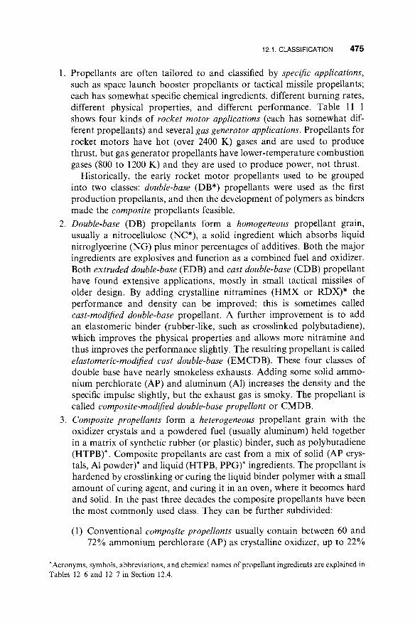
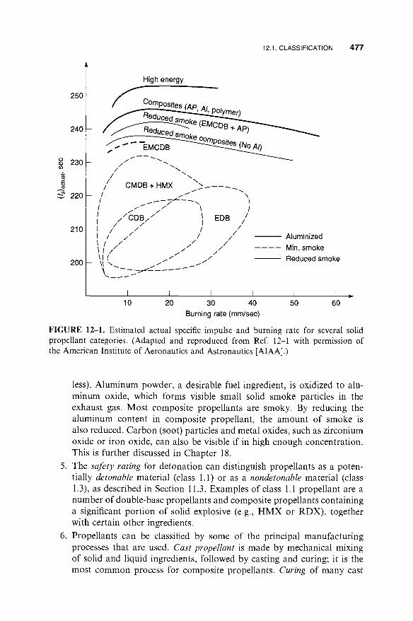
Figures 12-1 and 12-2 show the general regions for the specific impulse, burning rate, and density for the more common classes of propellants. Composite propellants give higher densities, specific impulse, and a wider range of burning rates. The ordinate in these figures is an actual or esti- mated specific impulse at standard conditions (1000 psi and expansion to sea-level atmosphere). It does not include any pressure drops in the cham- ber, any nozzle erosion, or an assumption about combustion losses and scaling. The composite propellants are shown to have a wide range of burning rates and densities; most of them have specific gravities between 1.75 and 1.81 and burning rates between 7 and 20 mm/sec. Table 12-1 lists performance characteristics for several propellants. The double-base (DB) propellants and the ammonium nitrate (AN) propellants have lower per- formance and density. Most composite propellants have almost the same performance and density but a wide range of burning rates. The highest performance is for a CMDB propellant whose ingredients are identified as DB/AP-HMX/A1, but it is only four percent higher.
Several of the classifications can be confusing. The term composite- modified double-base propellant (CMDB) has been used for (1) a DB propellant, where some AP, A1, and binder are added; (2) alternatively, the same propellant could be classified as a composite propellant to which some double-base ingredients have been added.
4. Propellants can be classified by the density of the smoke in the exhaust plume as smoky, reduced smoke, or minimum smoke (essentially smoke-
12.1. CLASSIFICATION 477
250
240
O 230
~ eeo
210
200
High energy
/ x
/ \ / CMDB + HMX \
- \ f / ---- "-- 7~-" -- "- ~
I f ~ ' ~ / \ / /
I / / C D B / / 1 i / I
/ I I / I
I / /
/ / / /
I I
I EDB / /
/ /
/ /
/ /
\I( / / \1 \ ~ / / / ~ I /
\ _ _-2 j . . . . . .
Aluminized
Min. smoke
Reduced smoke
I I I I I I -- 10 20 30 40 50 60
Burning rate (mm/sec)
FIGURE 12-1. Estimated actual specific impulse and burning rate for several solid propellant categories. (Adapted and reproduced from Ref. 12-1 with permission of the American Institute of Aeronautics and Astronautics [AIAA].)
,
less). Aluminum powder, a desirable fuel ingredient, is oxidized to alu- minum oxide, which forms visible small solid smoke particles in the exhaust gas. Most composite propellants are smoky. By reducing the aluminum content in composite propellant, the amount of smoke is also reduced. Carbon (soot) particles and metal oxides, such as zirconium oxide or iron oxide, can also be visible if in high enough concentration. This is further discussed in Chapter 18.
The safety rating for detonation can distinguish propellants as a poten- tially detonable material (class 1.1) or as a nondetonable material (class 1.3), as described in Section 11.3. Examples of class 1.1 propellant are a number of double-base propellants and composite propellants containing a significant portion of solid explosive (e.g., H M X or RDX), together with certain other ingredients.
Propellants can be classified by some of the principal manufacturing processes that are used. Cast propellant is made by mechanical mixing of solid and liquid ingredients, followed by casting and curing; it is the most common process for composite propellants. Curing of many cast
478 SOLID PROPELLANTS
(sec)
250 I - ~
240
230
Aluminized propellants
Minimum smoke propellants
Reduced smoke propellants
_ /CD . . ; , ; .
Composites
, High., energy
Composites "~ (AP, AI, polymer)\
1.60 1.65 1.70 1.75 1.85 Density (g/cm 3)
Reduced smoke EMCDB ~ . + AP + HMX
1.80
FIGURE 12-2. Estimated actual specific impulse and specific gravity for several solid propellant categories. (Adapted and reproduced from Ref. 12-1 with permission of the AIAA.)
propellants is by chemical reaction between binder and curing agent at elevated temperature (45 to 150°C); however, there are some that can be cured at ambient temperatures (20 to 25°C) or hardened by a nonchemi- cal process such as crystallization. Propellant can also be made by a solvation process (dissolving a plasticizer in a solid pelletized matrix, whose volume is expanded). Extruded propellant is made by mechanical mixing (rolling into sheets) followed by extrusion (pushing through a die at high pressure). Solvation and extrusion processes apply primarily to double-base propellants.
7. Propellants have also been classified by their principal ingredient, such as the principal oxidizer (ammonium perchlorate propellants, ammonium nitrate propellants, or azide-type propellants) or their principal binder or fuel ingredient, such as polybutadiene propellants or aluminized propel lants. This classification of propellants by ingredients is described in Section 12.4 and Table 12-8.
8. Propellants with toxic and nontoxic exhaust gases. This is discussed in more detail in Section 12.3.

TABLE 12-1. Characteristics of Some Operational Solid Propellants
Propellant Type a
Flame Density or Is Temperature e Spec. Gravity e Metal
Range Content (see) b (°F) (°K) (lb/in 3) (sp. gr.) (wt %)
Burning Pressure Rate C'e Exponent e Hazard
(in./sec) n Classification d
Stress (psi)/Strain (%)
-60OF + 150°F Processing
Method
DB 220-230 4100 2550 0.058 1.61 0 0.05-1.2 0.30 1.1 4600/2 DB/AP/A1 260-265 6500 3880 0.065 1.80 20-21 0.2-1.0 0.40 1.3 2750/5 DB/AP-HMX/A1 265-270 6700 4000 0.065 1.80 20 0.2-1.2 0.49 1.1 2375/3 PVC/AP/A1 260-265 5600 3380 0.064 1.78 21 0.3-0.9 0.35 1.3 369/150
PU/AP/A1 260-265 5700 3440 0.064 1.78 16-20 0.2-0.9 0.15 1.3 1170/6 PBAN/AP/A1 260-263 5800 3500 0.064 1.78 16 0.25-1.0 0.33 1.3 520/16
(at -10°F)
CTPB/AP/A1 260-265 5700 3440 0.064 1.78 15-17 0.25-2.0 0.40 1.3 325/26 HTPB/AP/A1 260-265 5700 3440 0.067 1.86 4-17 0.25-3.0 0.40 1.3 910/50 PBAA/AP/A1 260-265 5700 3440 0.064 1.78 14 0.25-1.3 0.35 1.3 500/13 AN/Polymer 180-190 2300 1550 0.053 1.47 0 0.06-0.5 0.60 1.3 200/5
490/60 Extruded 120/50 Extruded 50/33 Solvent cast 38/220 Cast or
extruded 75/33 Cast 71/28 Cast
88/75 Cast 90/33 Cast 41/31 Cast NA Cast
"AI, aluminum; AN, ammonium nitrate; AP, ammonium perchlorate; CTPB, carboxy-terminated polybutadiene; DB, double-base; HMX, cyclotetramethylene tetranitramine; HTPB, hydroxyl-terminatd poly- butadiene; PBAA, polybutadiene-acrylic acid polymer; PBAN, polybutadiene-acrylic acid-acrylonitrile terpolymer; PU, polyurethane; PVC, polyvinyl chloride. h At 1000 psia expanding to 14.7 psia, ideal or theoretical value at reference conditions. " At 1000 psia. a See page 491. e I,. flame temperature, density, burn rate and pressure exponent will vary slightly with specific composition.
,,q t,O

480 SOLID PROPELLANTS
A large variety of different chemical ingredients and propellant formulations have been synthesized, analyzed, and tested in experimental motors. Later we list many of them. Perhaps only 12 basic types of propellant are in common use today. Other types are still being investigated. Table 12-2 evaluates some of the advantages and disadvantages of several selected propellant classes. A typical propellant has between 4 and 12 different ingredients. Representative formula- tions for three types of propellant are given in Table 12-3. In actual practice, each manufacturer of a propellant has his own precise formulation and proces- sing procedure. The exact percentages of ingredients, even for a given propel- lant such as PBAN, not only vary among manufacturers but often vary from motor application to motor application. The practice of adjusting the mass percentage and even adding or deleting one or more of the minor ingredients (additives) is known as propellant tailoring. Tailoring is the practice of taking a well-known propellant and changing it slightly to fit a new application, differ- ent processing equipment, altered motor ballistics, storage life, temperature limits, or even a change in ingredient source.
New propellant formulations are normally developed using laboratory-size mixers, curing ovens, and related apparatus with the propellant mixers (1 to 5 liters) operated by remote control for safety reasons. Process studies usually accompany the development of the formulation to evaluate the "processibility" of a new propellant and to guide the design of any special production equip- ment needed in preparing ingredients, mixing, casting, or curing the propellant.
Historically, black powder (a pressed mixture of potassium nitrate, sulfur, and an organic fuel such as ground peach stones) was the first to be used. Other types of ingredients and propellants have been used in experimental motors, including fluorine compounds, propellants containing powdered beryllium, boron, hydrides of boron, lithium, or beryllium, or new synthetic organic plasticizer and binder materials with azide or nitrate groups. Most have not yet been considered satisfactory or practical for production in rocket motors.
12.2. PROPELLANT CHARACTERISTICS
The propellant selection is critical to rocket motor design. The desirable pro- pellant characteristics are listed below and are discussed again in other parts of this book. The requirements for any particular motor will influence the prio- rities of these characteristics:
1. High performance or high specific impulse; really this means high gas temperature and/or low molecular mass.
2. Predictable, reproducible, and initially adjustable burning rate to fit the need of the grain design and the thrust-time requirement.
3. For minimum variation in thrust or chamber pressure, the pressure or burning rate exponent and the temperature coefficient should be small.

12.2. PROPELLANT CHARACTERISTICS 481
10.
11.
12.
13.
14.
4. Adequate physical properties (including bond strength) over the intended operating temperature range.
5. High density (allows a small-volume motor).
6. Predictable, reproducible ignition qualities (such as reasonable ignition overpressure)
7. Good aging characteristics and long life. Aging and life predictions depend on the propellant's chemical and physical properties, the cumu- lative damage criteria with load cycling and thermal cycling (see page 461), and actual tests on propellant samples and test data from failed motors.
8. Low absorption of moisture, which often causes chemical deterioration.
9. Simple, reproducible, safe, low-cost, controllable, and low-hazard man- ufacturing.
Guaranteed availability of all raw materials and purchased components over the production and operating life of the propellant, and good control over undesirable impurities.
Low technical risk, such as a favorable history of prior applications.
Relative insensitivity to certain energy stimuli described in the next sec- tion.
Non-toxic exhaust gases.
Not prone to combustion instability (see next chapter).
Some of these desirable characteristics will apply also to all materials and purchased components used in solid motors, such as the igniter, insulator, case, or safe and arm device. Several of these characteristics are sometimes in conflict with each other. For example, increasing the physical strength (more binder and or more crosslinker) will reduce the performance and density. So a mod- ification of the propellant for one of these characteristics can often cause changes in several of the others.
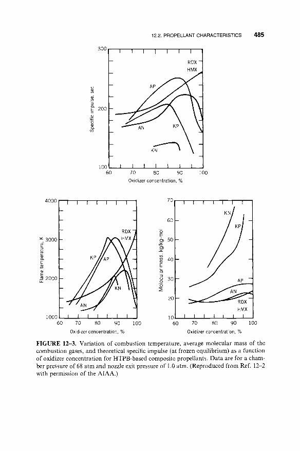
Several illustrations will now be given on how the characteristics of a propellant change when the concentration of one of its major ingredients is changed. For composition propellants using a polymer binder [hydroxyl-ter- minated polybutadiene (HTPB)] and various crystalline oxidizers, Fig. 12-3 shows the calculated variation in combustion or flame temperature, average product gas molecular weight, and specific impulse as a function of oxidizer concentration; this is calculated data taken from Ref. 12-2, based on a thermochemical analysis as explained in Chapter 5. The maximum values of Is and T 1 o c c u r at approximately the same concentration of oxidizer. In practice the optimum percentage for AP (about 90 to 93%) and AN (about 93%) cannot be achieved, because concentrations greater than about 90% total solids (including the aluminum and solid catalysts) cannot be processed in a mixer. A castable slurry that will flow into a mold requires 10 to 15% liquid content.

TABL-E 12-2. Characteristics of Selected Propellants
Propellant Type Advantages Disadvantages
Double-base (extruded)
Double-base (castable) safe to handle; simple, well-known process; modest cost; good
mechanical properties; good burn rate control; low temperature coefficient; plateau burning can be achieved
Composite-modified double-base or Higher performance; good mechanical properties; high density CMDB with some AP and A1 (sp. gr. 1.83-1.86); less likely to have combustion stability
problems; intermediate cost; good background experience
Composite AP, A1, and PBAN or PU or CTPB binder
Composite AP, A1, and HTPB binder; most common composite propellant today
Modified composite AP, A1, PB binder plus some HMX or RDX
Modest cost; nontoxic clean exhaust, smokeless; good burn rate Free-standing grain requires structural support; low control; wide range of burn rates; simple performance, low density; high to intermediate well-known process; good mechanical properties; low hazard in manufacture; can have storage temperature coefficient; very low pressure exponent; plateau problems with NG bleeding out; diameter limited burning is possible by available extrusion presses; class 1.1
Wide range of burn rates; nontoxic smokeless exhaust; relatively NG may bleed out or migrate; high to intermediate manufacture hazard; low performance; low density; higher cost than extruded DB; class 1.1
Storage stability can be marginal; complex facilities; some smoke in exhaust; high flame temperature; moisture sensitive; moderately toxic exhaust; hazards in manufacture; modest ambient temperature range; the value of n is high (0.8 to 0.9); moderately high temperature coefficient
Reliable; high density; long experience background; modest cost; Modest ambient temperature range; high viscosity good aging; long cure time; good performance; usually stable limits at maximum solid loading; high flame combustion; low to medium cost; wide temperature range; high temperature; toxic, smoky exhaust; some are density; low to moderate temperature sensitivity; good burn moisture sensitive; some burn-rate modifiers (e.g. rate control; usually good physical properties; class 1.3 aziridines) are carcinogens
Slightly better solids loading % and performance than PBAN or Complex facilities; moisture sensitive; fairly high CTPB; widest ambient temperature limits; good burn-rate flame temperature; toxic, smoky exhaust control; usually stable combustion; medium cost; good storage stability; widest range of burn rates; good physical properties; good experience; class 1.3
Higher performance; good burn-rate control; usually stable Expensive, complex facilities; hazardous processing; combustion; high density; moderate temperature sensitivity; can harder-to-control burn rate; high flame have good mechanical properties temperature; toxic, smoky exhaust; can be impact
sensitive; can be class 1.1; high cost; pressure exponent 0.5-0.7

Composite with energetic binder and plasticizer such as NG, AP, HMX
Modified double- base with HMX
Modified AN propellant with HMX or RDX added
Ammonium nitrate plus polymer binder (gas generator)
RDX/HMX with polymer
Highest performance; high density (1.8 to 1.86); narrow range of burn rates
Higher performance; high density (1.78 to 1.88); stable combustion; narrow range of burn rates
Fair performance; relatively clean; smokeless; nontoxic exhaust
Clean exhaust; little smoke; essentially nontoxic exhaust; low temperature gas; usually stable combustion; modest cost; low pressure exponent
Low smoke; nontoxic exhaust; lower combustion temperature
Expensive; limited experience; impact sensitive; high pressure exponent
Same as CMDB above; limited experience; most are class 1.1; high cost
Relatively little experience; can be hazardous to manufacture; need to stabilize AN to limit grain growth; low burn rates; impact sensitive; medium density; class 1.1 or 1.3
Low performance; low density; need to stabilize AN to limit grain growth and avoid phase transformations; moisture sensitive; low burn rates
Low performance; low density; class 1.1

484 SOLID PROPELLANTS
TABLE 12-3. Representative Propellant Formulations
Double-Base (JPN Propellant)
Composite (PBAN Propellant)
Composite Double-Base (CMDB Propellant)
Ingredient Wt % Ingredient Wt % Ingredient Wt %
Nitrocellulose 51.5 Ammonium 70.0 Ammonium 20.4 perchlorate perchlorate
Nitroglycerine 43.0 Aluminum powder 16 .0 Aluminum powder 21.1 Diethyl phthalate 3.2 Polybutadiene- 11.78 Nitrocellulose 21.9
acrylic acid- acrylonitrile
Ethyl centralite 1.0 Epoxy curative 2.22 Nitroglycerine 29.0 Potassium sulfate 1.2 Triacetin 5.1 Carbon black < 1% Stabilizers 2.5 Candelilla wax < 1%
Source: Courtesy of Air Force Phillips Laboratory, Edwards, California.
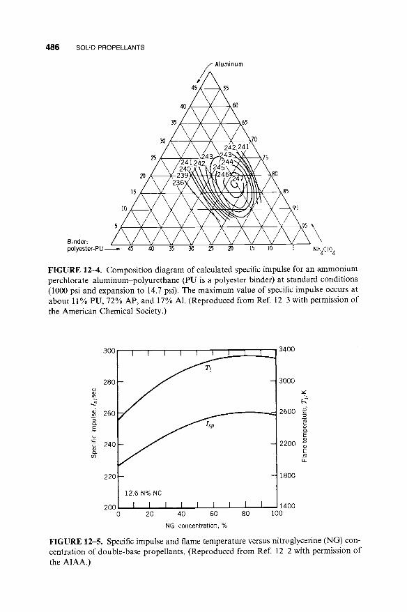
A typical composition diagram for a composite propellant is shown in Fig. 12-4. It shows how the specific impulse varies with changes in the composition of the three principal ingredients: the solid AP, solid A1, and viscoelastic poly- mer binder.
For double-base (DB) propellant the theoretical variations of Is and T1 are shown in Figs. 12-1 and 12-5 as a function of the nitroglycerine (NG) or plasticizer percentage. The theoretical maximum specific impulse occurs at about 80% NG. In practice, nitroglycerine, which is a liquid, is seldom found in concentrations over 60%, because the physical properties are poor if NG is high. There need to be other major solid or soluble ingredients to make a usable DB propellant.
For CMDB propellant the addition of either AP or a reactive nitramine such as RDX allows a higher Is than ordinary DB (where AP or RDX percent is zero), as shown in Fig. 12-6. Both AP and RDX greatly increase the flame temperature and make heat transfer more critical. The maximum values of Is occur at about 50% AP and at 100% RDX (which is an impractical propellant that cannot be manufactured and will not have reasonable physical properties). At high concentrations of AP or RDX the exhaust gases contain considerable H20 and 02 (as shown in Fig. 12-7); these enhance the erosion rate of carbon- containing insulators or nozzle materials. The toxic HC1 is present in concen- trations between 10 and 20%, but for practical propellants it seldom exceeds 14%.
Nitramines such as RDX or H M X contain relatively few oxidizing radicals, and the binder surrounding the nitramine crystals cannot be fully oxidized. The binder is decomposed at the combustion temperature, forms gases rich in hydrogen and carbon monoxide (which reduces the molecular weight), and
12.2. PROPELLANT CHARACTERIST ICS 4 8 5
300~
o
(29
(D
E 2 0 0 - ._
._ o
Q.
(29
100 60
I I I I I I
RDX HMX
70 80 90 Oxidizerconcentration, %
100
4000t_
3000 6
2000
1000 60
! I I I I I 1 4
1 RDX
70 80 90 100
Oxidizer concentration, %
70
60
0 E 6~ 5o x-
CD
c6 40
E
o 30 0
2O
10 60
I I I ! I I
KN
P
I "1 I I 70 80 90 100
Oxidizer concentration, %
FIGURE 12-3. Variation of combustion temperature, average molecular mass of the combustion gases, and theoretical specific impulse (at frozen equilibrium) as a function of oxidizer concentration for HTPB-based composite propellants. Data are for a cham- ber pressure of 68 atm and nozzle exit pressure of 1.0 atm. (Reproduced from Ref. 12-2 with permission of the AIAA.)
486 SOLID PROPELLANTS
Binder: polyester-PU
~ Aluminum
/ h / \
Is / V V \ k~\\\%'x"~/l ll\W \ 8s
= 45 40 35 30 25 N 15 I0 5 NH4CIO 4
FIGURE 12--4. Composition diagram of calculated specific impulse for an ammonium perchlorate-aluminum-polyurethane (PU is a polyester binder) at standard conditions (1000 psi and expansion to 14.7 psi). The maximum value of specific impulse occurs at about 11% PU, 72% AP, and 17% A1. (Reproduced from Ref. 12-3 with permission of the American Chemical Society.)
300 3400
TI
280 - 3000 (o
260 2600 • - , %
0. .
E . _ o .
,,., E "5 240 2200
E I t _
220 1800
2 0 0 ~ 1400 0 20 40 60 80 I00
NG concentration, %
FIGURE 12-5. Specific impulse and flame temperature versus nitroglycerine (NG) con- centration of double-base propellants. (Reproduced from Ref. 12-2 with permission of the AIAA.)

12.3. HAZARDS 487
300
280
260 m
- I
E
.~- 2 4 0
Q .
220
200 0
I I ! ! I I I I i
_ //I-- ~ ~ / /
// ~ \\
- - - - - - AP-CMDB \ \ RDX-CMDB \ \
I I I I I I I I ~ 50 1(
AP or RDX concentration, %
3400
3000
2600
E
2 2 0 0 ~
m
1800
1400 ~0
FIGURE 12--6. Specific impulse and flame temperature versus AP or RDX concentra- tion of AP-CMDB propellants. (Reproduced from Ref. 12-2 with permission of the AIAA.)
cools the gases to a lower combustion temperature. The exhaust gases of AP- based and RDX-based C M D B propellant are shown in Fig. 12-7. The solid carbon particles seem to disappear if the R D X content is high.
1 2 , 3 . H A Z A R D S
With proper precautions and equipment, all common propellants can be man- ufactured, handled, and fired safely. It is necessary to fully understand the hazards and the methods for preventing hazardous situations from arising. Each material has its own set of hazards; some of the more common ones are described briefly below and also in Refs. 12-4 and 12-5. Not all apply to each propellant.
I n a d v e r t e n t I g n i t i o n
If a rocket motor is ignited and starts combustion when it is not expected to do so, the consequences can include very hot gases, local fires, or ignition of adjacent rocket motors. Unless the motor is constrained or fastened down, its thrust will suddenly accelerate it to unanticipated high velocities or erratic flight paths that can cause damage. Its exhaust cloud can be toxic and corro- sive. Inadvertent ignition can be caused by these effects:

4118 SOLID PROPELLANTS
o"e 40 E o
o 30 u,...
O ~ 2o
10
p = 70 atm
H2
H20
HCI
N2 O ~ 60 70 80 90 100
AP concentration, %
50
a~ 40
E .___ ~ 30
O
:~ 20
10
0 60
- - p = 70 atm
CO
70 80 90 100
RDX concentration, %
FIGURE 12-7. Calculated combustion products of composite propellant with varying amounts of AP or RDX. (Adapted from Chapter 1 of Ref. 12-2 with permission of the AIAA.)
Stray or induced currents activate the igniter.
Electrostatic discharge causes a spark or arc discharge.
Fires cause excessive heating of motor exterior, which can raise the propel- lant temperature above the ignition point.
Impact (bullet penetration, or dropping the motor onto a hard surface).
Energy absorption from prolonged mechanical vibration can cause the pro- pellant to overheat.
An electromechanical system is usually provided that prevents stray currents from activating the igniter; it is called safe and arm system. It prevents ignition induced by currents in other wires of the vehicle, radar- or radio-frequency- induced currents, electromagnetic surges, or pulses from a nuclear bomb explo- sion. It prevents electric currents from reaching the igniter circuit during its

12.3. HAZARDS 489
"unarmed" condition. When put into the "arm" position, it is ready to accept and transmit the start signal to the igniter.
Electrostatic discharges (ESD) can be caused by lightning, friction of insu- lating materials, or the moving separation of two insulators. The buildup of a high electrostatic potential of thousands of volts can, upon discharge, allow a rapid increase in electric current, which in turn can lead to arcing or exothermic reactions along the current's path. For this reason all propellants, liners, or insulators should have sufficient electric conductivity to prevent the buildup of an electrostatic charge. The inadvertent ignition of a Pershing ground-to- ground missile is believed to have been caused by electrostatic discharge while in the transporter-erector vehicle. ESD is a function of the materials, their surface and volume resistivities, dielectric constants, and the breakdown voltages.
Viscoelastic propellants are excellent absorbers of vibration energy and can become locally hot when oscillated for extensive periods at particular frequen- cies. This can happen in designs where a segment of the grain is not well supported and is free to vibrate at natural frequencies. A propellant can also be accidentally ignited by various other energy inputs, such as mechanical friction or vibration. Standard tests have been developed to measure the pro- pellant's resistance to these energy inputs.
Aging and Useful Life
This topic was discussed briefly in the section on Structural Design in the previous chapter. The aging of a propellant can be measured with test motors and propellant sample tests if the loading during the life of the motor can be correctly anticipated. It is then possible to estimate and predict the useful shelf or storage life of a rocket motor (see Refs. 12-5 and 12-6). When a reduction in physical properties, caused by estimated thermal or mechanical load cycles (cumulative damage), has reduced the safety margin on the stresses and/or strains to a danger point, the motor is no longer considered to be safe to ignite and operate. Once this age limit or its predicted, weakened condition is reached, the motor has a high probability of failure. It needs to be pulled from the ready inventory, and the old aged propellant needs to be removed and replaced with new, strong propellant.
The life of a particular motor depends on the particular propellant, the frequency and magnitude of imposed loads or strains, the design, and other factors. Typical life values range from 5 to 25 years. Shelf life can usually be increased by increasing the physical strength of the propellants (e.g., by increasing the amount of binder), selecting chemically compatible, stable ingre- dients with minimal long-term degradation, or by minimizing the vibration loads, temperature limits, or number of cycles (controlled storage and trans- port environment).

490 SOLID PROPELLANTS
Case Overpressure and Failure
The motor case will break or explode if the chamber pressure exceeds the case's burst pressure. The release of high-pressure gas energy can cause an explosion; motor pieces could be thrown out into the adjacent area. The sudden depres- surization from chamber pressure to ambient pressure, which is usually below the deflagration limit, would normally cause a class 1.3 propellant to stop burning. Large pieces of unburned propellant can often be found after a violent case burst. This type of motor failure can be caused by one of the following phenomena:
1. The grain is overaged, porous, or severely cracked and/or has major unbonded areas due to severe accumulated damage.
2. There has been a significant chemical change in the propellant due to migration or slow, low-order chemical reactions. This can reduce the allowable physical properties, weakening the grain, so that it will crack or cause unfavorable increases in the burning rate. In some cases chemi- cal reactions create gaseous products which create many small voids and raise the pressure in sealed stored motors.
3. The motor is not properly manufactured. Obviously, careful fabrication and inspection are necessary.
4. The motor has been damaged. For example, a nick or dent in the case caused by improper handling will reduce the case strength. This can be prevented by careful handling and repeated inspections.
5. An obstruction plugs the nozzle (e.g., a loose large piece of insulation) and causes a rapid increase in chamber pressure.
6. Moisture absorption can degrade the strength and strain capabilities by a factor of 3 to 10 in propellants that contain hygroscopic ingredients. Motors are usually sealed to prevent humid air access.
Detonation versus Deflagration. When burning rocket motor propellant is overpressurized, it can either deflagrate (or burn) or detonate (explode vio- lently), as described in Table 12-4. In a detonation the chemical reaction en- ergy of the whole grain can be released in a very short time (microseconds), and in effect it becomes an explosive bomb. This detonation condition can happen with some propellants and some ingredients (e..g, nitroglycerine or HMX, which are described later in this chapter). Detonations can be minimized or avoided by proper design, correct manufacture, and safe handling and operat- ing procedures.
The same material may burn or detonate, depending on the chemical for- mulation, the type and intensity of the initiation, the degree of confinement, the physical propellant properties (such as density or porosity), and the geometric characteristics of the motor. It is possible for certain propellants to change suddenly from an orderly deflagration to a detonation. A simplified explana- tion of this transition starts with normal burning at rated chamber pressure;

T A B L E 12-4. C o m p a r i s o n of Burning and De tona t ion
12.3. HAZARDS 491
Burning
Characteristic With Air Within Rocket Motors Explosive
Detonation
Typical material Coal and air Propellant, no air
Common means of Heat Heat initiating reaction
Linear reaction rate 10 -6 0.2 to 5 × 10 -2 (m/see) (subsonic) (subsonic)
Produces shock No No waves
Time for completing 10 -1 10 -2 to 10 -3 reaction (see)
Maximum pressure 0.07-0.14 0.7-100 (100-14,500) [MPa (psi)] (1 0-20)
Process limitation By vaporization and heat transfer at burning surface
Increase in burning Potential Overpressure and rate can result in: furnace sudden failure of
failure pressure container
Rocket propellant or explosives
Shock wave; sudden pressure rise plus heat
2 to 9 × 10³ (supersonic)
Yes
10 -6
7000-70,000 (106-107 )
By physical and chemical properties of material, (e.g., density, composition)
Detonation and violent rapid explosion of all the propellant
the hot gas then penetrates pores or small cracks in the unburned propellant, where the local confinement can cause the pressure to become very high locally, the combustion front speeds up to shock wave speed with a low-pressure differential, and it then accelerates further to a strong, fast, high-pressure shock wave, characteristic of detonations. The degree and rigidity of the geo- metric confinement and a scale factor (e.g., larger-diameter grain) influence the severity and occurrence of detonations.
Hazard Classification. Propellants that can experience a transition from deflagration to detonation are considered more hazardous and are usually designated as class 1.1-type propellants. Most propellants will burn, the case may burst if chamber pressure becomes too high, but the propellant will not detonate and are class 1.3 propellants. The required tests and rules for deter- mining this hazard category are explained in Ref. 12-7. Propellant samples are subjected to various tests, including impact tests (dropped weight) and card gap tests (which determine the force needed to initiate a propellant detonation when a sample is subjected to a blast from a known booster explosive). If the case should burst violently with a class 1.3 propellant, much of the remaining unburnt propellant would be thrown out, but would then usually stop burning. With a class 1.1 propellant, a powerful detonation can sometimes ensue, which rapidly gasifies all the remaining propellant, and is much more powerful and destructive than the bursting of the case under high pressure. Unfortunately, the term "explosion" has been used to describe both a bursting of a case with

492 SOLID PROPELLANTS
its fragmentation of the motor and also the higher rate of energy release of a detonation, which leads to a very rapid and more energetic fragmentation of the motor.
The Department of Defense (DOD) classification of 1.1 or 1.3 determines the method of labeling and the cost of shipping rocket propellants, loaded military missiles, explosives, or ammunition; it also determines the required limits on the amount of that propellant stored or manufactured in any one site and the minimum separation distance of that site to the next building or site. The DOD system (Ref. 12-7) is the same as that used by the United Nations.
Insensitive Munitions
In military operations an accidental ignition and unplanned operation or an explosion of a rocket missile can cause severe damage to equipment and injure or kill personnel. This has to be avoided or minimized by making the motor designs and propellants insensitive to a variety of energy stimuli. The worst scenario is a detonation of the propellant, releasing the explosive energy of all of the propellant mass, and this scenario is to be avoided. The missiles and its motors must undergo a series of prescribed tests to determine their resistance to inadvertent ignition with the most likely energy inputs during a possible battle situation. Table 12-5 describes a series of tests called out in a military speci- fication, which are detailed in Refs. 12-8 and 12-9. A threat hazard assessment
must be made prior to the tests, to evaluate the logistic and operational threats during the missile's life cycle. The evaluation may cause some modifications to the test setups, changes in the passing criteria, or the skipping of some of these tests.
The missiles, together with their motors, are destroyed in these tests. If the motor should detonate (an unacceptable result), the motor has to be redesigned
TABLE 12-5. Testing for Insensitivity of Rockets and Missiles
Test Description Criteria for Passing
Fast cook off
Slow cook off Bullet impact
Fragment impact Sympathetic
detonation Shaped explosive
charge impact Spall impact
Build a fire (of jet fuel or wood) underneath No reaction more severe than the missile or its motor burning
Gradual heating (6°F/hr) to failure Same as above One to three 50 caliber bullets fired at short Same as above
intervals Small high-speed steel fragment Same as above Detonation from an adjacent similar motor No detonation of test motor
or a nearby specific munition Blast from specified shaped charge in No detonation
specified location Several high-speed spalled fragments from a Fire, but no explosion or
steel plate which is subjected to a shaped detonation charge

12.3. HAZARDS 493
and/or have a change in propellant. There are some newer propellants that are more resistant to these stimuli and are therefore preferred for tactical missile applications, even though there is usually a penalty in propulsion performance. If explosions (not detonations) occur, it may be possible to redesign the motor and mitigate the effects of the explosion (make it less violent). For example, the case can have a provision to vent itself prior to an explosion. Changes to the shipping container can also mitigate some of these effects. If the result is a fire (an acceptable result), it should be confined to the particular grain or motor. Under some circumstances a burst failure of the case is acceptable.
Upper Pressure Limit
If the pressure-rise rate and the absolute pressure become extremely high (as in some impact tests or in the high acceleration of a gun barrel), some propellants will detonate. For many propellants these pressures are above approximately 1500 MPa or 225,000 psi, but for others they are lower (as low as 300 MPa or 45,000 psi). They represent an upper pressure limit beyond which a propellant should not operate.
Toxicity
A large share of all rockets do not have a significant toxicity problem. A number of propellant ingredients (e.g., some crosslinking agents and burning rate catalysts) and a few of the plastics used in fiber-reinforced cases can be dermatological or respiratory toxins; a few are carcinogens (cancer-causing agents) or suspected carcinogens. They, and the mixed uncured propellant containing these materials, have to be handled carefully to prevent operator exposure. This means using gloves, face shields, good ventilation, and, with some high-vapor-pressure ingredients, gas masks. The finished or cured grain or motor is usually not toxic.
The exhaust plume gases can be very toxic if they contain beryllium or berylium oxide particles, chlorine gas, hydrochloric acid gas, hydrofluoric acid gas, or some other fluorine compounds. When an ammonium perchlorate oxidizer is used, the exhaust gas can contain up to about 14% hydrochloric acid. For large rocket motors this can be many tons of highly toxic gas. Test and launch facilities for rockets with toxic plumes require special precautions and occasionally special decontamination processes, as explained in Chapter 20.
Safety Rules
The most effective way to control hazards and prevent accidents is (1) to train personnel in the hazards of each propellant of concern and to teach them how to avoid hazardous conditions, prevent accidents, and how to recover from an accident; (2) to design the motors, facilities, and the equipment to be safe; and

494 SOLID PROPELLANTS
(3) to institute and enforce rigid safety rules during design, manufacture, and operation. There are many such rules. Examples are no smoking and no matches in areas where there are propellants or loaded motors, wearing spark-proof shoes and using spark-proof tools, shielding all electrical equip- ment, providing a water-deluge fire extinguishing system in test facilities to cool motors or extinguish burning, or proper grounding of all electrical equipment and items that could build up static electrical charges.
12.4. PROPELLANT INGREDIENTS
A number of relatively common propellant ingredients are listed in Table 12-6 for double-base propellants and in Table 12-7 for composite-type solid pro- pellants. They are categorized by major function, such as oxidizer, fuel, binder, plasticizer, curing agent, and so on, and each category is described in this section. However, several of the ingredients have more than one function. These lists are not complete and at least 200 other ingredients have been tried in experimental rocket motors.
A classification of modern propellants, including some new types that are still in the experimental phase, is given in Table 12-8, according to their bin- ders, plasticizers, and solid ingredients; these solids may be an oxidizer, a solid fuel, or a combination or compound of both.
The ingredient properties and impurities can have a profound effect on the propellant characteristics. A seemingly minor change in one ingredient can cause measurable changes in ballistic properties, physical properties, migra- tion, aging, or ease of manufacture. When the propellant's performance or ballistic characteristics have tight tolerances, the ingredient purity and proper- ties must also conform to tight tolerances and careful handling (e.g., no expo- sure to moisture). In the remainder of this section a number of the important ingredients, grouped by function, are briefly, discussed.
Inorganic Oxidizers
Some of the thermochemical properties of several oxidizers and oxygen radical- containing compounds are listed in Table 12-9. Their values depend on the chemical nature of each ingredient.
Ammonium perchlorate (NH4C104) is the most widely used crystalline oxi- dizer in solid propellants. Because of its good characteristics, including com- patibility with other propellant materials, good performance, quality, uniformity, and availability, it dominates the solid oxidizer field. Other solid oxidizers, particularly ammonium nitrate and potassium perchlorate, were used and occasionally are still being used in production rockets but to a large extent have been replaced by more modern propellants containing ammo- nium perchlorate. Many oxidizer compounds were investigated during the 1970s, but none reached production status.

12.4. PROPELLANT INGREDIENTS 495
TABLE 12-6. Typical Ingredients of Double-Base (DB) Propellants and Composite- Modified Double-Base (CMDB) Propellants
Type Percent Acronym Typical Chemicals
Binder 30-50 NC
Reactive plasticizer (liquid explosive)
Plasticizer (organic liquid fuel)
20-50
0-10
Burn-rate modifier up to 3
Coolant Opacifier
Stabilizer and or antioxidant
Visible flame suppressant
Lubricant (for extruded propellant only)
Metal fuel a Crystalline oxidizer a
Solid explosive crystals a
NG DEGDN TEGDN PDN TMETN DEP TA DMP
EC DBP
PbSa PbSt CuSa CuSt OXM C
DED > 1 EC
DPA
KNO3 up to 2 K2SO 4 >0.3 C
0-15 A1 { AP
0-15 AN HMX
0-20 RDX NQ
Nitrocellulose (solid), usually plasticized with 20 to 50% nitroglycerine
Nitroglycerine Diethylene glycol dinitrate Triethylene glycol dinitrate Propanedial-dinitrate Trimethylolethane trinitrate Diethyl phthalate Triacetin Dimethyl phthalate Dioctile phthalate Ethyl centralite Dibutyl phthalate
Lead salicylate Lead stearate Copper salicylate Copper stearate Oxamine Carbon black (powder or graphite
powder) Diethyl diphenyl Ethyl centralite Diphenyl amine
Potassium nitrate Potassium sulphate Graphite Wax
Aluminum, fine powder (solid) Ammonium perchlorate Ammonium nitrate Cyclotetramethylenetetranitramine Cyclotrimethylenetrinitramine Nitroguanadine
a Several of these, but not all, are added to CMDB propellant.
The oxidizing potential of the perchlorates is generally high, which makes this material suited to high specific impulse propellants. Both ammonium and potassium perchlorate are only slightly soluble in water, a favorable trait for propellant use. All the perchlorate oxidizers produce hydrogen chloride (HC1) and other toxic and corrosive chlorine compounds in their reaction with fuels. Care is required in firing rockets, particularly the very large rockets, to safe- guard operating personnel or communities in the path of exhaust gas clouds. Ammonium perchlorate (AP) is supplied in the form of small white crystals. Particle size and shape influences the manufacturing process and the propellant burning rate. Therefore, close control of the crystal sizes and the size distribu-

496 SOLID PROPELLANTS
TABLE 12-7. Typical Ingredients of Composite Solid Propellants
Type Percent Acronym Typical Chemicals
Oxidizer (crystalline)
Metal fuel (also acts as a combustion stabilizer)
Fuel/Binder, polybutadiene type
Fuel/Binder, polyether and polyester type
Curing agent or crosslinker, which reacts with polymer binder
Burn-rate modifier
Explosive filler (solid)
Plasticizer/Pot life control (organic liquid)
0-70
0-30
5-18
0-15
0.2-3.5
0.2-3
0-40
0-7
AP AN KP KN
DN A1 Be
Zr
I HTPB CTPB PBAN PBAA PEG PCP PGA PPG HTPE PU MAPO IPDI TDI HMDI DDI TMP BITA FeO nBF
HMX RDX NQ DOP DOA DOS DMP IDP
Ammonium perchlorate Ammonium nitrate Potassium perchlorate Potassium nitrate Ammonium dinitramine Aluminum Beryllium (experimental propellant
only) Zirconium (also acts as burn-rate
modifier) Hydroxyl-terminated polybutadiene Carboxyl-terminated polybutadiene Polybutadiene acrylonitrile acrylic acid Polybutadiene acrylic acid Polyethylene glycol Polycaprolactone polyol Polyglycol adipate Polypropylene glycol Hydroxyl-terminated polyethylene Polyurethane polyester or polyether Methyl aziridinyl phosphine oxide Isophorone diisocyanate Toluene-2,4-diisocyanate Hexamethylene diisocyanide Dimeryl diisocyanate Trimethylol propane Trimesoyl- 1 (2-ethyl)-aziridine Ferric oxide n-Butyl ferrocene Oxides of Cu, Pb, Zr, Fe Alkaline earth carbonates Alkaline earth sulfates Metallo-organic compounds Cyclotetramethylenetetranitramine Cyclotrimethylenetrinitramine Nitroguanadine
Dioctyl phthalate Dioctyl adipate Dioctyl sebacate Dimethyl phthalate Isodecyl pelargonate

TABLE 12-7. (Continued)
12.4. PROPELLANT INGREDIENTS 497
Type Percent Acronym Typical Chemicals
Energetic plasticizer (liquid)
Energetic fuel/ binder
0-14
0-15
GAP NG DEGDN BTTN TEGDN TMETN PCP GAP PGN BAMO/AMMO
BAMO/NMMO
Bonding agent >0.1 MT-4 (improves bond to solid HX-752 particles)
Stabilizer I DPA (reduces chemical > 0.5 NMA deterioration)
Processing aid > 0.5
Glycidyl azide polymer Nitroglycerine Diethylene glycol dinitrate Butanetriol trinitrate Triethylene glycol dinitrate Trimethylolethane trinitrate Polycaprolactone polymer Glycidyl azide polymer Propylglycidyl nitrate Bis-azidomethyloxetane/Azidomethyl-
methyloxetane copolymer Bis-azidomethyloxetane/Nitramethyl-
methyloxetane copolymer MAPO-tartaric acid-adipic acid
condensate Bis-isophthal-methyl-aziridine
Diphenylamine Phenylnaphthylamine N-methyl-p-nitroaniline Dinitrodiphenylanine Lecithin Sodium lauryl sulfate
tion present in a given quantity or batch is required. AP crystals are rounded (nearly ball shaped) to allow easier mixing than sharp, fractured crystals. They come in sizes ranging from about 600 [arn (l[arn - 10 -6 m) diameter to about 80 [am from the factory. Sizes below about 40 [am diameter are considered hazardous (can easily be ignited and sometimes detonated) and are not shipped; instead, the propellant manufacturer takes larger crystals and grinds them (at the motor factory) to the smaller sizes (down to 2 [am) just before they are incorporated into a propellant.
The inorganic nitrates are relatively low-performance oxidizers compared with perchlorates. However, ammonium nitrate is used in some applications because of its very low cost and smokeless and relatively nontoxic exhaust. Its principal use is with low-burning-rate, low-performance rocket and gas generator applications. Ammonium nitrate (AN) changes its crystal structure at several phase transformation temperatures. These changes cause slight changes in volume. One phase transformation at 32°C causes about a 3.4% change in volume. Repeated temperature cycling through this transition tem- perature creates tiny voids in the propellant, and causes growth in the grain and a change in physical or ballistic properties. The addition of a small amount

TABLE 12-8. Classification of Solid Rocket Propellants Used in Flying Vehicles According to their Binders, Plasticizers, and Solid Ingredients
Solid Oxidizer Propellant Designation Binder Plasticizer and/or Fuel Application
Double-base, DB Plasticized NC NG, TA, etc.
CMDB a Plasticized NC NG, TMETN, TA, BTTN, etc.
Same Same Same Same
EMCDB a Plasticized NC + elastomeric polymer
Polybutadiene HTPB
HTPB
CTPB, PBAN, PBAA
TPE a Thermoplastic elastomer
PEG, PPG, PCP, PGA, and mixtures
GAP, PGN, BAMO/ NMMO, BAMO/AMMO
Polyether and polyesters
Energetic binder (other than NC)
Same
DOA, IDP, DOP, DOA, etc.
Same
None Minimum signature and smoke
A1, AP, KP Booster, sustainer, and spacecraft
HMX, RDX, AP Reduced smoke HMX, RDX, azides Minimum signature, gas
generator Like CMDB above, but generally superior mechanical properties
with elastomer added as binder Booster, sustainer or
spacecraft; used extensively in many applications
Reduced smoke, gas generator
A1, AP, KP, HMX, RDX
AN, HMX, RDX, some AP
All like HTPB above, but somewhat lower performance due to higher processing viscosity and consequent lower solids content. Still used in applications with older designs
Similar to HTPB, but without chemical curing process. TPEs cure (crosslink) via selective crystallization of certain parts of the binder. Still are experimental propellants
DOA, IDP, TMETN, DEGDN, etc. A1, AP, KP, HMX Booster, sustainer, or spacecraft
TMETN, BTTN, etc. GAP-azide, Like polyether/polyester propellants above, but with slightly GAP-nitrate, NG higher performance. Experimental propellant.
a CMDB, composite-modified double-base; EMCDB, elastomer-modified cast double-base; TPE, thermoplastic elastomer. For definition of acronyms and abbreviation of propellant ingredients see Tables 12-6 and 12-7.

12.4. PROPELLANT INGREDIENTS 499
TABLE 12-9. Comparison of Crystalline Oxidizers
Molecular Oxygen Chemical Mass Density Content
Oxidizer Symbol (kg/kg-mol) (kg/m 3) (wt %) Remarks
Ammonium NH4C10 4 117.49 1949 54.5 Low n, low cost, perchlorate readily available
Potassium KC10 4 138.55 2519 46.2 Low burning rate, perchlorate medium
performance Sodium NaC104 122.44 2018 52.3 Hygroscopic, high
perchlorate performance Ammonium NH4NO 3 80.0 1730 60.0 Smokeless, medium
nitrate performance Potassium KNO3 101.10 2109 47.5 Low cost, low
nitrate performance
of stabilizer such as nickel oxide (NiO) or potassium nitrate (KNO3) seems to change the transition temperature to above 60°C, a high enough value so that normal ambient temperature cycling will no longer cause recrystallization (Refs. 12-10 and 12-11). AN with such an additive is known as phase-stabilized ammonium nitrate (PSAN). AN is hygroscopic, and the absorption of moisture will degrade propellant made with AN.
Fuels
This section discusses solid fuels. Powdered spherical aluminum is the most common. It consists of small spherical particles (5 to 60 lam diameter) and is used in a wide variety of composite and composite-modified double-base pro- pellant formulations, usually constituting 14 to 20% of the propellant by weight. Small aluminum particles can burn in air and this powder is mildly toxic if inhaled. During rocket combustion this fuel is oxidized into aluminum oxide. These oxide particles tend to agglomerate and form larger particles. The aluminum increases the heat of combustion, the propellant density, the com- bustion temperature, and thus the specific impulse. The oxide is in liquid droplet form during combustion and solidifies in the nozzle as the gas tem- perature drops. When in the liquid state the oxide can form a molten slag which can accumulate in pockets (e.g., around an impropely designed sub- merged nozzle), thus adversely affecting the vehicle's mass ratio. It also can deposit on walls inside the combustion chamber, as described in Refs. 12-12 and 14-13.
Boron is a high-energy fuel that is lighter than aluminum and has a high melting point (2304°C). It is difficult to burn with high efficiency in combustion chambers of reasonable length. However, it can be oxidized at reasonable

500 SOLID PROPELLANTS
efficiency if the boron particle size is very small. Boron is used advantageously as a propellant in combination rocket-air-burning engines, where there is ade- quate combustion volume and oxygen from the air.
Beryllium burns much more easily than boron and improves the specific impulse of a solid propellant motor, usually by about 15 sec, but it and its oxide are highly toxic powders absorbed by animals and humans when inhaled. The technology with composite propellants using powdered beryllium fuel has been experimentally proven, but its severe toxicity makes its application unlikely.
Theoretically, both aluminum hydride (A1H3) and beryllium hydride (BeH2) are attractive fuels because of their high heat release and gas-volume contribu- tion. Specific impulse gains are 10 to 15 sec for AlzH3 and 25 to 30 sec for BeH2. Both are difficult to manufacture and both deteriorate chemically during storage, with loss of hydrogen. These compounds are not used today in practical fuels.
Binders
The binder provides the structural glue or matrix in which solid granular ingredients are held together in a composite propellant. The raw materials are liquid prepolymers or monomers. Polyethers, polyesters and poly-buta- dienes have been used (see Tables 12-6 and 12-7). After they are mixed with the solid ingredients, cast and cured, they form a hard rubber-like material that constitutes the grain. Polyvinylchloride (PVC) and polyurethane (PU) (Table 12-1) were used 40 years ago and are still used in a few motors, mostly of old design. Binder materials are also really fuels for solid propel- lant rockets and are oxidized in the combustion process. The binding ingre- dient, usually a polymer of one type or another, has a primary effect on motor reliability, mechanical properties, propellant processing complexity, storability, aging, and costs. Some polymers undergo complex chemical reac- tions, crosslinking, and branch chaining during curing of the propellant. HTPB has been the favorite binder in recent years, because it allows a some- what higher solids fraction (88 to 90% of AP and A1) and relatively good physical properties at the temperature limits. Several common binders are listed in Tables 12-1, 12-6 and 12-7. Elastomeric binders have been added to plasticized double-base-type nitrocellulose to improve physical properties. Polymerization occurs when the binder monomer and its crosslinking agent react (beginning in the mixing process) to form long-chain and complex three-dimensional polymers. Other types of binders, such as PVC, cure or plasticize without a molecular reaction (see Refs. 12-2, 12-3, and 12-13). Often called plastisol-type binders, they form a very viscous dispersion of a powdered polymerized resin in nonvolatile liquid. They polymerize slowly by interaction.

12.4. PROPELLANT INGREDIENTS 501
Burning-Rate Modifiers
A burning-rate catalyst or burning-rate modifier helps to accelerate or decele- rate the combustion at the burning surface and increases or decreases the value of the propellant burning rate. It permits the tailoring of the burning rate to fit a specific grain design and thrust-time curve. Several are listed in Tables 12-6 and 12-7. Some, like iron oxide or lead stearate, increase the burning rate; however, others, like lithium fluoride, will reduce the burning rate of some composite propellants. The inorganic catalysts do not contribute to the com- bustion energy, but consume energy when they are heated to the combustion temperature. These modifiers are effective because they change the combustion mechanism, which is described in Chapter 13. Chapter 2 of Ref. 12-2 gives examples of how several modifiers change the burning rate of composite pro- pellants.
Plasticizers
A plasticizer is usually a relatively low-viscosity liquid organic ingredient which is also a fuel. It is added to improve the elongation of the propellant at low temperatures and to improve processing properties, such as lower viscosity for casting or longer pot life of the mixed but uncured propellants. The plasticizers listed in Tables 12-6, 12-7, and 12-8 show several plasticizers.
Curing Agents or Crosslinkers
A curing agent or crosslinker causes the prepolymers to form longer chains of larger molecular mass and interlocks between chains. Even though these mate- rials are present in small amounts (0.2 to 3%), a minor change in the percen- tage will have a major effect on the propellant physical properties, manufacturability, and aging. It is used only with composite propellants. It is the ingredient that causes the binder to solidify and become hard. Several curing agents are listed in Table 12-7.
Energetic Binders and Plasticizers
Energetic binders and/or plasticizers are used in lieu of the conventional organic materials. They contain oxidizing species (such as azides or organic nitrates) as well as organic species. They add some additional energy to the propellant causing a modest increase in performance. They serve also as a binder to hold other ingredients, or as an energetic plasticizer liquid. They can self-react exothermally and burn without a separate oxidizer. Glycidyl azide polymer (GAP) is an example of an energetic, thermally stable, hydro- xyl-terminated prepolymer that can be polymerized. It has been used in experi-

502 SOLID PROPELLANTS
ental propellants. Other energetic binder or plasticizer materials are listed in Tables 12-6, 12-7 and 12-8.
Organic Oxidizers or Explosives
Organic oxidizers are explosive organic compounds with - - N O 2 radical or other oxidizing fractions incorporated into the molecular structure. References 12-2 and 12-13 describe their properties, manufacture, and application. These are used with high-energy propellants or smokeless propellants. They can be crystalline solids, such as the nitramines HMX or RDX, fibrous solids such as NC, or energetic plasticizer liquids such as D E G N or NG. These materials can react or burn by themselves when initiated with enough activating energy, but all of them are explosives and can also be detonated under certain conditions. Both H M X and RDX are stoichiometrically balanced materials and the addi- tion of either fuel or oxidizer only will reduce the T1 and Is values. Therefore, when binder fuels are added to hold the HMX or RDX crystals in a viscoelastic matrix, it is also necessary to add an oxidizer such as AP or AN.
RDX and H M X are quite similar in structure and properties. Both are white crystalline solids that can be made in different sizes. For safety, they are shipped in a desensitizing liquid, which has to be removed prior to propellant processing. H M X has a higher density, a higher detonation rate, yields more energy per unit volume, and has a higher melting point. NG, NC, HMX, and RDX are also used extensively in military and commercial explosives. H M X or RDX can be included in DB, CMDB, or composite propellants to achieve higher performance or other characteristics. The percentage added can range up to 60% of the propellant. Processing propellant with these or similar ingre- dients can be hazardous, and the extra safety precautions make the processing more expensive.
Liquid nitroglycerine (NG) by itself is very sensitive to shock, impact, or friction. It is an excellent plasticizer for propellants when desensitized by the addition of other materials (liquids like triacetin or dibutyl phthalate) or by compounding with nitrocellulose. It is readily dissolved in many organic sol- vents, and in turn it acts as a solvent for NC and other solid ingredients (Ref. 12-13).
Nitrocellulose (NC) is a key ingredient in DB and CMDB propellant. It is made by the acid nitration of natural cellulose fibers from wood or cotton and is a mixture of several organic nitrates. Although crystalline, it retains the fiber structure of the original cellulose (see Ref. 12-13). The nitrogen content is important in defining the significant properties of nitrocellulose and can range from 8 to 14%, but the grades used for propellant are usually between 12.2 and 13.1%. Since it is impossible to make NC from natural products with an exact nitrogen content, the required properties are achieved by careful blending. Since the solid fiber-like NC material is difficult to make into a

12.4. PROPELLANT INGREDIENTS 503
grain, it is usually mixed with NG, DEGN, or other plasticizer to gelatinize or solvate it when used with DB and CMDB propellant.
Additives
Small amounts of additives are used for many purposes, including accelerating or lengthening the curing time, improving the rheological properties (easier casting of viscous raw mixed propellant), improving the physical properties, adding opaqueness to a transparent propellant to prevent radiation heating at places other than the burning surface, limiting migration of chemical species from the propellant to the binder or vice versa, minimizing the slow oxidation or chemical deterioration during storage, and improving the aging characteris- tics or the moisture resistance. Bonding agents are additives to enhance adhe- sion between the solid ingredients (AP or A1) and the binder. Stabilizers are intended to minimize the slow chemical or physical reactions that can occur in propellants. Catalysts are sometimes added to the crosslinker or curing agent to slow down the curing rate. Lubricants aid the extrusion process. Desensitizing agents help to make a propellant more resistant to inadvertent energy stimulus. These are usually added in very small quantities.
Particle-Size Parameters
The size, shape, and size distribution of the solid particles of AP, A1 or HMX in the propellant can have a major influence on the composite propellant char- acteristics. The particles are spherical in shape, because this allows easier mix- ing and a higher percentage of solids in the propellant than shapes of sharp- edged natural crystals. Normally, the ground AP oxidizer crystals are graded according to particle size ranges as follows:
Coarse 400 to 600 ~tm (1 ~tm = 10 - 6 m) Medium 50 to 200 lam Fine 5 to 15 tam Ultrafine submicrometer to 5 ~tm
Coarse and medium-grade AP crystals are handled as class 1.3 materials, whereas the fine and ultrafine grades are considered as class 1.1 high explosives and are usually manufactured on-site from the medium or coarse grades. (See Section 12.3 for a definition of these explosive hazard classifications.) Most propellants use a blend of oxidizer particle sizes, if only to maximize the weight of oxidizer per unit volume of propellant, with the small particles filling part of the voids between the larger particles.
Figure 12-8 shows the influence of varying the ratio of coarse to fine oxidi- zer particle sizes on propellant burning rate and also the influence of a burning rate additive. Figure 12-9 shows that the influence of particle size of the alu- minum fuel on propellant burning rate is much less pronounced than that of oxidizer particle size. Figure 12-8 also shows the effect of particle size. Particle

5 0 4 SOLID PROPELLANTS
0.80
0.76 ¢ j Q) (/1
• -~ 0.72
= 0.68 ¢. .
L
m
0.64
0.60 65
j j Strand Wburner: 600 psi, 80°F
t35 60/40 55/45 50/50 Coarse/fine ratio
FIGURE 12-8. Typical effect of oxidizer (ammonium perchlorate) particle size mixture and burning rate additive on the burning rate of a composite propellant. (From NASA report SP-72262, Motor Propellant Development, July l, 1967.)
size range and particle shape of both the oxidizer [usually ammonium perchlo- rate (AP)] and solid fuel (usually aluminum) have a significant effect on the solid packing fraction and the rheological properties (associated with the flow- ing or pouring of viscous liquids) of uncured composite propellant. By defini- tion, the packing fraction is the volume fraction of all solids when packed to minimum volume (a theoretical condition). High packing fraction makes mix- ing, casting, and handling during propellant fabrication more difficult. Figure 12-10 shows the distribution of AP particle size using a blend of sizes; the shape of this curve can be altered drastically by controlling the size ranges and ratios. Also, the size range and shape of the solid particles affect the solids loading ratio, which is the mass ratio of solid to total ingredients in the uncured propellants. Computer-optimized methods exist for adjusting particle-size dis- tributions for improvement of the solids loading. The solids loading can be as
0.23
t .)
.__. 0.22
.E 0.21 e -
m
0.20 0
c~
I I I Strand burner: 500 psi, room temperature
o ~
10 20 30 40 50 60 Particle size, pm
FIGURE 12-9. Typical effect of aluminum particle size on propellant burning rate for a composite propellant. (From NASA Report 8075, Solid Propellant Processing Factors in Rocket Motor Design, October 1971.)

12.5. OTHER PROPELLANT CATEGORIES 505
m" ._o
w..
0 .- , . , (I}
E 0
E
e -
E I,..
{..
30
20
A I r
0 0 100 400 200 300
Particle diameter, pm
F I G U R E 12-10. The oxidizer (AP) particle size distribution is a blend of two or more different particle sizes; this particular composite propellant consists of a narrow cut at about 10 pm and a broad region from 50 to 200 pm.
high as 90% in some composite propellants. High solids loading, desired for high performance, introduces complexity and higher costs into the processing of propellant. Trade-off among ballistic (performance) requirements, processi- bility, mechanical strength, rejection rates, and facility costs is a continuing problem with many high-specific-impulse composite propellants. References 12-2 and 12-13 give information on the influence of particle size on motor performance.
A monomodal propellant has one size of solid oxidizer particles, a bimodal has two sizes (say, 20 and 200 pm), and a trimodal propellant has three sizes, because this allows a larger mass of solids to be placed into the propellant. Problem 12-1 has a sketch that explains how the voids between the large particles are filled with smaller particles.
12.5. OTHER PROPELLANT CATEGORIES
Gas Generator Propellants
Gas generator propellants produce hot gas but not thrust. They usually have a low combustion temperature (800 to 1600 K), and most do not require insu- lators when used in metal cases. Typical applications of gas generators were listed in Table 11-1. A large variety of propellants have been used to create hot gas for gas generators, but only a few will be mentioned.
Stabilized AN-based propellants have been used for many years with various ingredients or binders. They give a clean, essentially smokeless exhaust and a low combustion temperature. Because of their low burning rate they are useful for long-duration gas generator applications, say 30 to 300 sec. Typical c o r n -

506 SOLID PROPELLANTS
positions are shown in Ref. 12-11, and a typical propellant is described in Table 12-10.
One method of reducing flame temperature is to burn conventional hot AP propellant and then add water to it to cool the gases to a temperature where uncooled metals can contain them. This is used on the MX missile launcher tube gas generator (Ref. 12-14). Another formulation uses HMX or RDX with an excess of polyether- or polyester-type polyurethane.
For the inflation of automobile collision safety bags the exhaust gas must be nontoxic, smoke free, have a low temperature (will not burn people), be quickly initiated, and be reliably available. One solution is to use alkali azides (e.g., NaN3 or KN3) with an oxide and an oxidizer. The resulting nitrates or oxides are solid materials that are removed by filtering and the gas is clean and is largely moderately hot nitrogen. In one model, air can be aspirated into the air
TABLE 12-10. Typical Gas Generator Propellant using Ammonium Nitrate Oxidizer
Ballistic Properties
Calculated flame temperature (K) 1370 Burning rate at 6.89 MPa and 20°C (mm/sec) 2.1 Pressure exponent n (dimensionless) 0.37 Temperature sensitivity ap (%/K) 0.22 Theoretical characteristic velocity, c* (m/sec) 1205 Ratio of specific heats 1.28 Molecular weight of exhaust gas 19
Composition (Mass Fraction)
Ammonium nitrate (%) 78 Polymer binder plus curing agent (%) 17 Additives (processing aid, stabilizer, antioxidant) (%) 5 Oxidizer particle size, (gm) 150
Exhaust Gas Composition (Molar %)
Water 26 Carbon monoxide 19 Carbon dioxide 7 Nitrogen 21 Hydrogen 27 Methane Trace
Physical Properties at 25°C or 298 K
Tensile strength (MPa) 1.24 Elongation (%) 5.4 Modulus of elasticity in tension (N/m 2) 34.5 Specific gravity 1.48

12.5. OTHER PROPELLANT CATEGORIES 507
bag by the hot, high-pressure gas (see Ref. 12-15). One particular composition uses 65 to 75% NAN3, 10 to 28% Fe203, 5 to 16% NaNO3 as an oxidizer, a burn rate modifier, and a small amount of SiO 2 for moisture absorption. The resultant solid nitride slag is caught in a filter.
The power P delivered by a gas generator can be expressed as
P - &(hi - h2) -- [rhT1Rk/(k - 1)][1 - (p2/Pl) (k-1)/k] (12-1)
where rh is the mass flow rate, hi and h2 the enthalpies per unit mass, respec- tively, at the gas generator chamber and exhaust pressure conditions, T1 is the flame temperature in the gas generator chamber, R the gas constant, P2/Pl is the reciprocal of the pressure ratio through which these gases are expanded, and k the specific heat ratio. Because the flame temperature is relatively low there is no appreciable dissociation, and frozen equilibrum calculations are usually adequate.
Smokeless or Low-Smoke Propellant
Certain types of DB propellant, DB modified with HMX, and AN composites can be nearly smokeless. There is no or very little particulate matter in the exhaust gas. These minimum-smoke propellants are not a special class with a peculiar formulation but a variety of one of the classes mentioned previously. Propellants containing A1, Zr, Fe203 (burn rate modifier), or other metallic species will form visible clouds of small solid metal or metal oxide particles in the exhaust.
For certain military applications a smokeless propellant is needed and the reasons are stated in Chapter 18 (Exhaust Plumes). It is very difficult to make a propellant which has a truly smokeless exhaust gas. We therefore distinguish between low-smoke also called minimum-smoke (almost smokeless), and reduced-smoke propellants, which have a faintly visible plume. A visible smoke trail comes from solid particles in the plume, such as aluminum oxide. With enough of these particles, the exhaust plume will scatter or absorb light and become visible as primary smoke. The particles can act as focal points for moisture condensation, which can occur in saturated air or under high humidity, low temperature conditions. Also, vaporized plume molecules, such as water or hydrochloric acid, can condense in cold air and form droplets and thus a cloud trail. These processes create a vapor trail or secondary smoke.
Several types of DB propellant, DB modified with HMX, nitramine (HMX or RDX) based composites, AN composites, or combinations of these, give very few or no solid particles in their exhaust gas. They do not contain alumi- num or AP, generally have lower specific impulse than comparable propellants with AP, and have very little primary smoke, but can have secondary smoke in unfavorable weather. Several of these propellants have been used in tactical missiles.

508 SOLID PROPELLANTS
Reduced-smoke propellants are usually composite propellants with low con- centrations of aluminum (1 to 6%); they have a low percentage of aluminum oxide in the exhaust plume, are faintly visible as primary smoke, but can precipitate heavy secondary smoke in unfavorable weather. Their performance is substantially better than that of minimum-smoke propellants, as seen in Fig. 12-1.
Igniter Propellants
The process of propellant ignition is discussed in Section 13.2, and several types of igniter hardware are discussed in Section 14.3. Propellants for igniters, a specialized field of propellant technology, is described here briefly. The require- ments for an igniter propellant will include the following:
Fast high heat release and high gas evolution per unit igniter propellant mass to allow rapid filling of grain cavity with hot gas and partial pres- surization of the chamber.
Stable initiation and operation over a wide range of pressures (subatmo- spheric to chamber pressure) and smooth burning at low pressure with no ignition overpressure surge.
Rapid initiation of igniter propellant burning and low ignition delays.
Low sensitivity of burn rate to ambient temperature changes and low burn- ing rate pressure exponent.
Operation over the required ambient temperature range.
Safe and easy to manufacture, safe to ship and handle.
Good aging characteristics and long life.
Minimal moisture absorption or degradation with time.
Low cost of ingredients and fabrication.
Some igniters not only generate hot combustion gas, but also hot solid particles or hot liquid droplets, which radiate heat and impinge on the propellant sur- face, embed themselves into this surface, and assist in achieving propellant burning on the exposed grain surface.
There have been a large variety of different igniter propellants and their development has been largely empirical. Black powder, which was used in early motors, is no longer favored, because it is difficult to duplicate its properties. Extruded double-base propellants are used frequently, usually as a large num- ber of small cylindrical pellets. In some cases rocket propellants that are used in the main grain are also used for the igniter grain; sometimes they are slightly modified. They are used in the form of a small rocket motor within a large motor that is to be ignited. A common igniter formulation uses 20 to 35% boron and 65 to 80% potassium nitrate with 1 to 5% binder. Binders typically include epoxy resins, graphite, nitrocellulose, vegetable oil, polyisobutylene, and other binders listed in Table 12-7. Another formulation uses magnesium

12.6. LINERS, INSULATORS, AND INHIBITORS 509
with a fluorocarbon (Teflon); it gives hot particles and hot gas (Refs. 12-16 and 12-17). Other igniter propellants are listed in Ref. 12-18.
12.6. LINERS, INSULATORS, AND INHIBITORS
These three layers at the interface of a grain were defined in Section 11.3. Their materials do not contain any oxidizing ingredients; they will ablate, cook, char, vaporize, or distintegrate in the presence of hot gases. Many will burn if the hot combustion gas contains even a small amount of oxidizing species, but they will not usually burn by themselves. The liner, internal insulator, or inhibitor must be chemically compatible with the propellant and each other to avoid migration (described below) or changes in material composition; they must have good adhesive strength, so that they stay bonded to the propellant, or to each other. The temperature at which they suffer damage or experience a large surface regression should be high. They should all have a low specific gravity, thus reducing inert mass. Typical materials are neoprene (specific gravity 1.23), butyl rubber (0.93), a synthetic rubber called ethylenepropylene diene or EPDM (0.86), or the binder used in the propellant, such as polybutadiene (0.9 to 1.0); these values are low compared with a propellant specific gravity of 1.6 to 1.8. For low-smoke propellant these three rubber-like materials should give off some gas, but few, if any, solid particles (see Ref. 12-19).
In addition to the desired characteristics listed in the previous paragraph, the liner should be a soft stretchable rubber-type thin material (typically 0.02 to 0.04 in. thick with 200 to 450% elongation) to allow relative movement along the bond line between the grain and the case. This differential expansion occurs because the thermal coefficient of expansion of the grain is typically an order of magnitude higher than that of the case. A liner will also seal fiber-wound cases (particularly thin cases), which are often porous, so that high-pressure hot gas cannot escape. A typical liner for a tactical guided missile has been made from polypropylene glycol (about 57%), a titanium oxide filler (about 20%), a di- isocyanate crosslinker (about 20%), and minor ingredients such as an antiox- idant. The motor case had to be preheated to about 82°C prior to application. Ethylenepropylene diene monomer (EPDM) is linked into ethylenepropylene diene terpolymer to form a synthetic rubber which is often used as polymer for liners; it adheres and elongates nicely.
In some motors today the internal insulator not only provides for the ther- mal protection of the case from the hot combustion gases, but also often serves the function of the liner for good bonding between propellant and insulator or insulator and case. Most motors still have a separate liner and an insulating layer. The thermal internal insulator should fulfill these additional requirements:
1. It must be erosion resistant, particularly in the insulation of the motor aft end or blast tube. This is achieved in part by using tough elastomeric

510 SOLID PROPELLANTS
materials, such as neoprene or butyl rubber, that are chemically resistant to the hot gas and the impact of particulates. This surface integrity is also achieved by forming a porous black carbon layer on its heated surface called a porous char layer, which remains after some of the interstial materials have been decomposed and vaporized.
2. It must provide good thermal resistance and low thermal conductivity to limit heat transfer to the case and thus keep the case below its maximum allowable temperature, which is usually between 160 and 350°C for the plastic in composite material cases and about 550 and 950°C for most steel cases. This is accomplished by filling the insulator with silicon oxide, graphite, Kevlar, or ceramic particles. Asbestos is an excellent filler mate- rial, but is no longer used because of its health hazard.
3. It should allow a large-deformation or strain to accommodate grain deflections upon pressurization or temperature cycling, and transfer loads between the grain and the case.
4. The surface regression should be minimal so as to retain much of its original geometric surface contour and allow a thin insulator.
A simple relationship for the thickness d at any location in the motor depends on the exposure time te, the erosion rate re (obtained from erosion tests at the likely gas velocity and temperature), and the safety factor f which can range from 1.2 to 2.0:
d = tere f (12-2)
Some designers use the simple rule that the insulation depth is twice the charred depth.
The thickness of the insulation is not usually uniform; it can vary by a factor of up to 20. It is thicker at locations such as the aft done, where it is exposed for longer intervals and at higher scrubbing velocities than the insulator layers protected by bonded propellant. Before making a material selection, it is neces- sary to evaluate the flow field and the thermal environment (combustion tem- perature, gas composition, pressure, exposure duration, internal ballistics) in order to carry out a thermal analysis (erosion prediction and estimated thick- ness of insulator). An analysis of loads and the deflections under loads at different locations of the motor are needed to estimate shear and compression stresses. If it involves high stresses or a relief flap, a structural analysis is also needed. Various computer programs, such as the one mentioned in Refs. 12-20 and 12-21, are used for these analyses.
An inhibitor is usually made of the same kinds of materials as internal insulators. They are applied (bonded, molded, glued, or sprayed) to grain surfaces that should not burn. In a segmented motor, for example (see Fig. 14-2), where burning is allowed only on the internal port area, the faces of the cylindrical grain sections are inhibited.

12.7. PROPELLANT PROCESSING AND MANUFACTURE 511
Migration is the transfer of mobile (liquid) chemical species from the solid propellant to the liner, insulator, or inhibitor, or vice versa. Liquid plasticizers such as NG or DEGN or unreacted monomers or liquid catalysts are known to migrate. This migratory transfer occurs very slowly; it can cause dramatic changes in physical properties (e.g., the propellant next to the liner becomes brittle or weak) and there are several instances where nitroglycerine migrated into an insulator and made it flammable. Migration can be prevented or inhib- ited by using (1) propellants without plasticizers, (2) insulators or binders with plasticizers identical to those used in propellants, (3) a thin layer of an imper- vious material or a migration barrier (such as PU or a thin metal film), and (4) an insulator material that will not allow.migration (e.g., PU) (see Ref. 12-22).
The graphite-epoxy motors used to boost the Delta launch vehicle use a three-layer liner: EPDM (ethylenepropylene diene terpolymer) as a thin primer to enhance bond strength, a polyurethane barrier to prevent migration of the plasticizer into the EPDM liner, and a plasticized HTPB-rich liner to prevent burning next to the case-bond interface. The composite AP-A1 propellant also uses the same HTPB binder.
Liners, insulators, or inhibitors can be applied to the grain in several ways: by painting, coating, dipping, spraying, or by gluing a sheet or strip to the case or the grain. Often an automated, robotic machine is used to achieve uniform thickness and high quality. Reference 12-21 describes the manufacture of par- ticular insulators.
An external insulation is often applied to the outside of the motor case, particularly in tactical missiles or high-acceleration launch boosters. This insu- lation reduces the heat flow from the air boundary layer outside the vehicle surface (which is aerodynamically heated) to the case and then to the propel- lant. It thus prevents fiber-reinforced plastic cases from becoming weak or the propellant from becoming soft or, in extreme situations, from being ignited. This insulator must withstand the oxidation caused by aerodynamically heated air, have good adhesion, have structural integrity to loads imposed by the flight or launch, and must have a reasonable cure temperature. Materials ordinarily used as internal insulators are unsatisfactory, because they burn in the atmo- sphere and generate heat. The best is a nonpyrolyzing, low-thermal-conductiv- ity refractory material (Ref. 12-23) such as high-temperature paint. The internal and external insulation also helps to reduce the grain temperature fluctuations and thus the thermal stresses imposed by thermal cycling, such as day-night variations or high- and low-altitude temperature variations for airborne missiles.
12.7. PROPELLANT PROCESSING AND MANUFACTURE
The manufacture of solid propellant involves complex physical and chemical processes. In the past, propellant has been produced by several different pro- cesses, including the compaction or pressing of powder charges, extrusion of

512 SOLID PROPELLANTS
propellant through dies under pressure using heavy presses, and mixing with a solvent which is later evaporated. Even for the same type of propellant (e.g., double-base, composite, or composite double-base) the fabrication processes are usually not identical for different manufacturers, motor types, sizes, or propellant formulation, and no single simple generalized process flowsheet or fabrication technique is prevalent. Most of the rocket motors in production today use composite-type propellants and therefore some emphasis on this process is given here.
Figure 12-11 shows a representative flowsheet for the manufacture of a complete solid rocket motor with a composite propellant made by batch pro- cesses. Processes marked with an asterisk are potentially hazardous, are usually operated or controlled remotely, and are usually performed in buildings designed to withstand potential fires or explosions. The mixing and casting processes are the most complex and are more critical than other processes in determining the quality, performance, burn rate, and physical properties of the resulting propellant.
The rheological properties of the uncured propellant, meaning its flow prop- erties in terms of shear rate, stress, and time, are all-important to the proces- sibility of the propellant, and these properties usually change substantially throughout the length of the processing line. Batch-type processing of propel- lant, including the casting (pouring) of propellant into motors that serve as their own molds, is the most common method. For very large motors several days are needed for casting perhaps 40 batches into a single case, forming a single grain. Vacuum is almost always imposed on the propellant during the mixing and casting operations to remove air and other dispersed gases and to avoid air bubbles in the grain. Viscosity measurements of the mixed propellant (10,000 to 20,000 poise) are made for quality control. Vacuum, temperature, vibration, energy input of the mixer, and time are some of the factors affecting the viscosity of the uncured propellant. Time is important in terms of pot life, that period of time the uncured propellant remains reasonably fluid after mix- ing before it cures and hardens. Short pot life (a few hours) requires fast operations in emptying mixers, measuring for quality control, transporting, and casting into motors. Some binder systems, such as those using PVC, give a very long pot life and avoid the urgency of haste in the processing line. References 12-3, 12-18, and 12-24 give details on propellant processing techniques and equipment.
Double-base propellants and modified double-base propellants are manu- factured by a different set of processes. The key is the diffusion of the liquid nitroglycerine into the fibrous solid matrix or nitrocellulose, thus forming, by means of solvation, a fairly homogeneous, well-dispersed, relatively strong solid material. Several processes for making double-base rocket propellant are in use today, including extrusion and slurry casting. In the slurry casting process the case (or the mold) is filled with solid casting powder (a series of small solid pellets of nitrocellulose with a small amount of nitroglycerine) and the case is then flooded with liquid nitroglycerine, which then solvates the
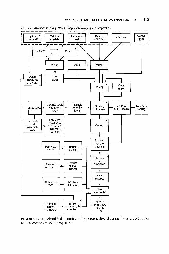
12.7. PROPELLANT PROCESSING AND MANUFACTURE 513
Chemical ingredients receiving, storage, inspection, weighing and preparation
i Igniter *[ Oxidizer chemicals crystals
/ ~ - - Classify I ;~~, I
\ /
Aluminum Binder [ powder (monomer) Additives
Grind *1
Weigh, "1 blend, mix and cure
Weigh
Dry, blend
Store H
I
~ C'ean~a00'yl I Cure case insulator &
liner I I
Fa bricate Fa bricateJ and mold aft &
assemble fwd. domes, case insulators
& flaps
Inspect, assemble
& test H
Fabricate nozzle
Safe and arm device
Fabricate TVC
Fabricate igniter
hardware
t-t Inspect & clean
H Electrical h test & inspect
, , ,
H C'ests I-- i ,& inspect
H Igniter assembly & check-out
Premix
w
Mixing
1
Casting into case
.Curing
Remove mandrel & tooling
Machine off excess propellant
X-ray inspect
Final assembly
Inspect, check-out,
pack & ship
I Clean *1 mixer
* L J Clean&. * U Fabricate ~ repair tooling ~ t o o l i n g .
"t
J
Curing i l agent II
L__'J
FIGURE 12-11. Simplified manufacturing process flow diagram for a rocket motor and its composite solid propellant.

514 SOLID PROPELLANTS
pellets. Figure 12-12 shows a simplified diagram of a typical setup for a slurry cast process. Double-base propellant manufacturing details are shown in Refs. 12-3 and 12-13.
Mandrels are used during casting and curing to assure a good internal cavity or perforation. They are made of metal in the shape of the internal bore (e.g., star or dogbone) and are often slightly tapered and coated with a nonbonding material, such as Teflon, to facilitate the withdrawal of the mandrel after curing without tearing the grain. For complicated internal passages, such as a conocyl, a complex built-up mandrel is necessary, which can be withdrawn through the nozzle flange opening in smaller pieces or which can be collapsed.
Hot air Fixture for supply for appling pressure Vacuum or
cure during cure air exhaust \ \ for cure
To vacuum pump
Trap
Window \ Pit cover Piston \ "x,_ / ram
I Pressurized hydraulic fluid Regulated
pressure air supply
/ Solvent tank
Solvent (NG)
Motor case
Casting pit
Motor support
Bed of casting powder (pellets)
Solvent supply pipe
Advancing level of solvent liquid during casting
Distributor plate with
small holes
Solvent distributor cap
FIGURE 12-12. Simplified diagram of one system for slurry casting and initial curing of a double-base solid propellant.
PROBLEMS 515
Some manufacturers have had success in making permanent mandrels (which are not withdrawn but stay with the motor) out of lightweight foamed propel- lant, which burns very quickly once it is ignited.
An important objective in processing is to produce a propellant grain free of cracks, low-density areas, voids, or other flaws. In general, voids and other flaws degrade the ballistic and mechanical properties of the propellant grain. Even the inclusion of finely dispersed gas in a propellant can result in an abnormally high burning rate, one so high as to cause catastrophic motor failure.
The finished grain (or motor) is usually inspected for defects (cracks, voids, and debonds) using x-ray, ultrasonic, heat conductivity, or other nondestruc- tive inspection techniques. Samples of propellant are taken from each batch, tested for rheological properties, and cast into physical property specimens and/or small motors which are cured and subsequently tested. A determination of the sensitivity of motor performance, including possible failure, to propel- lant voids and other flaws often requires the test firing of motors with known defects. Data from the tests are important in establishing inspection criteria for accepting and rejecting production motors.
Special process equipment is needed in the manufacture of propellant. For composite propellants this includes mechanical mixers (usually with two or three blades rotating on vertical shafts agitating propellant ingredients in a mixer bowl under vacuum), casting equipment, curing ovens, or machines for automatically applying the liner or insulation to the case. Double-base processing requires equipment for mechanically working the propellant (roll- ers, presses) or special tooling for allowing a slurry cast process. Computer- aided filament winding machines are used for laying the fibers of fiber-rein- forced plastic cases and nozzles.
PROBLEMS
1. Ideally the solid oxidizer particles in a propellant can be considered spheres of uni- form size. Three sizes of particles are available: coarse at 500 ~tm, medium at 50 ~tm, and fine at 5 ~tm, all at a specific gravity of 1.95, and a viscoelastic fuel binder at a specific gravity of 1.01. Assume that these materials can be mixed and vibrated so that the solid particles will touch each other, there are no voids in the binder, and the particles occupy a minimum of space similar to the sketch of the cross section shown here. It is desired to put 94 wt % of oxidizer into the propellant mix, for this will give maximum performance. (a) Determine the maximum weight percentage of oxidizer if only coarse crystals are used or if only medium-sized crystals are used. (b) Determine the maximum weight of oxidizer if both coarse and fine crystals are used, with the fine crystals filling the voids between the coarse particles. What is the optimum relative proportion of coarse and fine particles to give a maximum of oxidizer? (c) Same as part (b), but use coarse and medium crystals only. Is this better and, if so, why? (d) Using all three sizes, what is the ideal weight mixture ratio and what is the maximum oxidizer content possible and the theoretical maximum specific gravity of

516 SOLID PROPELLANTS
the propellant? (Hint: The centers of four adjacent coarse crystals form a tetrahedron whose side length is equal to the diameter.)
2. Suggest one or two specific applications (intercontinental missile, anti-aircraft, space launch vehicle upper stage, etc.) for each of the propellant categories listed in Table 12-2 and explain why it was selected when compared to other propellants.
3. Prepare a detailed outline of a procedure to be followed by a crew operating a propellant mixer. This 1 m 3 vertical solid propellant mixer has two rotating blades, a mixing bowl, a vacuum pump system to allow mix operations under vacuum, feed chutes or pipes with valves to supply the ingredients, and variable-speed electric motor drive, a provision for removing some propellant for laboratory samples, and a double-wall jacket around the mixing bowl to allow heating or cooling. It is known that the composite propellant properties are affected by mix time, small deviations from the exact composition, the temperature of the mix, the mechanical energy added by the blades, the blade speed, and the sequence in which the ingre- dients are added. It is also known that bad propellant would be produced if there are leaks that destroy the vacuum, if the bowl, mixing blades, feed chutes, and so on, are not clean but contain deposits of old propellant on their walls, if they are not mixed at 80°C, or if the viscosity of the mix becomes excessive. The sequence of loading ingredients shall be: (1) prepolymer binder, (2) plasticizer, (3) minor liquid additives, (4) solid consisting of first powdered aluminum and thereafter mixed bimodal AP crystals, and (5) finally the polymerizing agent or crosslinker. Refer to Fig. 12-11. Samples of the final liquid mix are taken to check viscosity and density. Please list all the sequential steps that the crew should undertake before, during, and after the mixing operation. If it is desired to control to a specific parameter (weight, duration, etc.), that fact should be stated; however, the specific data of ingredient mass, time, power, temperature, and so on, can be left blank. Mention all instruments (e.g., thermometers, wattmeter, etc.) that the crew should have and identify those that they must monitor closely. Assume that all ingredients were found to be of the desired composition, purity, and quality.
4. Determine the longitudinal growth of a 24-in.-long free-standing grain with a linear thermal coefficient of expansion of 7.5 x 10⁻⁵/°F for temperature limits of -40 to

PROBLEMS 517
140°F. Answer: 0.32 in.
5. The following data are given for an internally burning solid propellant grain with inhibited end faces and a small initial port area:
Length 40 in. Port area 27 in. 2 Propellant weight 240 lb Initial pressure at front end of chamber 1608 psi Initial pressure at nozzle end of chamber 1412 psi Propellant density 0.060 lb/in. 3 Vehicle acceleration 21.2 go
Determine the initial forces on the propellant supports produced by pressure differ- ential and vehicle acceleration. Answers: 19,600 lbf, 5090 lbf.
6. A solid propellant unit with an end-burning grain has a thrust of 4700 N and a duration of 14 sec. Four different burning rate propellants are available, all with approximately the same performance and the same specific gravity, but different AP mix and sizes and different burning rate enhancements. They are 5.0, 7.0, 10, and 13 mm/sec. The preferred L/D is 2.60, but values of 2.2 to 3.5 are acceptable. The impulse-to-initial-weight ratio is 96 at an L/D of 2.5. Assume optimum nozzle expan- sion. Chamber pressure is 6.894 MPa or 1000 psia and the operating temperature is 20°C or 68°F. Determine grain geometry, propellant mass, hardware mass, and initial mass.
7. For the rocket in Problem 6 determine the approximate chamber pressure, thrust, and duration at 245 and 328 K. Assume the temperature sensitivity (at a constant value of Ab/At) of 0.01%/K does not change with temperature.
8. A fuel-rich solid propellant gas generator propellant is required to drive a turbine of a liquid propellant turbopump. Determine its mass flow rate. The following data are given:
Chamber pressure Pl = 5 MPa Combustion temperature T 1 = 1500 K Specific heat ratio k = 1.25 Required pump input power 970 kW Turbine outlet pressure 0 psia Turbine efficiency 65% Molecular weight of gas 22 kg/kg-mol Pressure drop between gas
generator and turbine nozzle inlet 0.10 MPa
Windage and bearing friction is 10 kW. Neglect start transients. Answer: rh = 0.257 kg/sec.
9. The propellant for this gas generator has these characteristics:
Burn rate at standard conditions 4.0 mm/sec Burn time 110 sec Chamber pressure 5.1 MPa

518 SOLID PROPELLANTS
Pressure exponent n 0.55 Propellant specific gravity 1.47
Determine the size of an end-burning cylindrical grain. Answer: Single end-burning grain 27.2 cm in diameter and 31.9 cm long, or two end- burning opposed grains (each 19.6 cm diameter x 31.9 cm long) in a single chamber with ignition of both grains in the middle of the case.
REFERENCES
12-1.
12-2.
12-3.
12-4.
12-5.
12-6.
12-7.
12-8.
12-9.
12-10.
12-11.
12-12.
A Davenas, "Solid rocket Motor Design," Chapter 4 of G. E. Jensen and D. W. Netzer (Eds.), Tactical Missile Propulsion, Vol. 170, Progress in Astronautics and Aeronautics, AIAA, 1996.
N. Kubota, "Survey of Rocket Propellants and their Combustion Characteristics," Chapter 1 in K. K. Kuo and M. Summerfield (Eds.), Fundamentals of Solid-Propellant Combustion. Progress in Astronautics and Aeronautics, Vol. 90, American Institute of Aeronautics and Astronautics, New York, 1984.
C. Boyars and K. Klager, Propellants." Manufacture, Hazards and Testing, Advances in Chemistry Series 88, American Chemical Society, Washington, DC, 1969.
Chemical Propulsion Information Agency, Hazards of Chemical Rockets and Propellants. Vol. II, Solid Rocket Propellant Processing, Handling, Storage and Transportation, NTIS AD-870258, May 1972.
H. S. Sibdeh and R. A. Heller, "Rocket Motor Service Life Calculations Based on First Passage Method," Journal of Spacecraft and Rockets, Vol. 26, No. 4, July-August 1989, pp. 279-284.
D. I. Thrasher, "State of the Art of Solid Propellant Rocket Motor Grain Design in the United States," Chapter 9 in Design Methods in Solid Rocket Motors, Lecture Series LS 150, AGARD/NATO, April 1988.
"Explosive Hazard Classification Procedures," DOD, U.S. Army Technical Bulletin TB 700-2, updated 1989 (will become a UN specification).
"Hazards Assessment Tests for Non-Nuclear Ordnance," Military Standard MIL-STD-2105B (Government-issued Specification), 1994.
"Department of Defense--Ammunition and Explosive Safety Standard." U.S. Department of Defense, U.S. Army TB 700-2, U.S. Navy NAVSEAINST 8020.8, U.S. Air Force TO 11A-1-47, Defense Logistics Agency DLAR 8220.1, 1994 rev.
G. M. Clark and C. A. Zimmerman, "Phase Stabilized Ammonium Nitrate Selection and Development," JANNAF Publication 435, October 1985, pp. 65-75.
J. Li and Y. Xu, "Some Recent Investigations in Solid Propellant Technology for Gas Generators," AIAA Paper 90-2335, July 1990.
S. Boraas, "Modeling Slag Deposition in the Space Shuttle Solid Motor," Journal of Spacecraft and Rockets, Vol. 21, No. 1, January-February 1984, pp. 47-54.

REFERENCES 519
12-13. V. Lindner, "Explosives and Propellants," Kirk-Othmer, Encyclopedia of Chemical Technology, Vol. 9, pp. 561-671, 1980.
12-14. J. A. McKinnis and A. R. O'Connell, "MX Launch Gas Generator Development," Journal of Spacecraft and Rockets, Vol. 20, No. 3, May-June 1983.
12-15. T. H. Vos and G. W. Goetz, "Inflatable Restraint Systems, Helping to Save Lives on the Road," Quest, published by TRW, Inc., Redondo Beach, CA, Vol. 12, No. 2, Winter 1989-1990, pp. 2-27.
12-16. A. Peretz, "Investigation of Pyrotechnic MTV Compositions for Rocket Motor Igniters," Journal of Spacecraft and Rockets, Vol. 21, No. 2, March-April 1984, pp. 222-224.
12-17. G. Frut, "Mistral Missile Propulsion System," AIAA Paper 89-2428, July 1989 (B-KNO3 ignition).
12-18. A. Davenas, Solid Rocket Propulsion Technology, Pergamon Press, 1993 (origin- ally published in French, 1988).
12-19. J. L. Laird and R. J. Baker, "A Novel Smokeless Non-flaking Solid Propellant Inhibitor," Journal of Propulsion and Power, Vol. 2, No. 4, July-August 1986, pp. 378-379.
12-20. M. Q. Brewster, "Radiation-Stagnation Flow Model of Aluminized Solid Rocket Motor Insulation Heat Transfer," Journal of Thermophysics, Vol. 3, No. 2, April 1989, pp. 132-139.
12-21. A. Truchot, "Design of Solid Rocket Motor Internal Insulation," Chapter 10 in Design Methods in Solid Rocket Motors, Lecture Series LS 150, AGARD/ NATO, April 1988.
12-22. M. Probster and R. H. Schmucker, "Ballistic Anomalies in Solid Propellant Motors Due to Migration Effects," Acta Astronautica, Vol. 13, No. 10, 1986, pp. 599-605.
12-23. L. Chow and P. S. Shadlesky, "External Insulation for Tactical Missile Motor Propulsion Systems," AIAA Paper 89-2425, July 1989.
12-24. W. W. Sobol, "Low Cost Manufacture of Tactical Rocket Motors," Proceedings of 1984 JANNAF Propulsion Meeting, Vol. II, Chemical Propulsion Information Agency, Johns Hopkins University, Columbia, MD, 1984, pp. 219-226.


![Multiscale modeling of solid propellants: From particle ...kmatous/Papers/CST_PPF.pdfMultiscale modeling of solid propellants: From particle packing to failure ... [14,15] in their](https://img.pdfslide.net/doc/110x75/5e303401d8d85d52b9043444/multiscale-modeling-of-solid-propellants-from-particle-kmatouspaperscstppfpdf.jpg)