Embed Size (px)
Citation preview

ORNL is managed by UT-Battelle
for the US Department of Energy
Solid-State Body-in-White Spot Joining of Al to AHSS at Prototype Scale
PI: Zhili Feng
Oak Ridge National Laboratory
Honda R&D Americas, Arconic, Dow Chemical, L&L,
Cosma Engineering, G-NAC
MegaStir Technologies
Brigham Young University, Ohio State University
June 12, 2019 Project ID: mat155
This presentation does not contain any proprietary, confidential,
or otherwise restricted information

2 Mat155_2019
Overview
• Project start date: Nov. 2014
• Project end date: Dec. 2019
• Percent complete: 70%
Timeline
• Project participantsHonda R&D Americas, Alcoa, Dow
Chemical, L&L, Cosma Engineering, G-
NAC, MegaStir Technologies
Brigham Young University, Ohio State
University
• Project leadOak Ridge National Laboratory (ORNL)
Partners
• Total Project Budget: $3,187K
• DOE Share: $1,500K
• Recipient Share: $1,687K
• Funding for FY18: $500K
• Funding for FY19: $0K
Budget
• Barriers addressed
Joining and assembly. High-volume, high-yield joining technologies for lightweight and dissimilar materials needs further improvement
Barriers
* 2017 U.S. DRIVE MTT Roadmap Report, Section 4

3 Mat155_2019
Relevance
• Objectives: Develop, mature, and validate near-production
readiness of a solid-state spot joining technology to join
prototype-scale auto body-in-white (BIW) sub-systems made of
advanced high-strength steel (AHSS) and 7000/6000 series
high-strength aluminum alloys, to meet the dissimilar metal
joining challenges in high volume mass production.
• Impact: The project focuses on spot joint - the most common
form of joints in BIW structures of high volume production
vehicles. Thus, it enables the broadest insertion of lightweight
materials in BIW, and has the highest potential as a joining
technology to support the reduction of petroleum consumption,
environmental impacts, and economic benefits in the
transportation sector.

4 Mat155_2019
Sub-System Assembly
(Length of Line representative of
application)
Sub-System Assembly
(Combination of AHSS/UHSS and
HSA)
7xxx Aluminum
•DP1180•AlSi Coated Boron Steel
AHSS underbody
High strength Al upperbody
AHSS 7xxx
Adhesives/insulator
Cross-section of beam
Joint details
Future Sedan Structure
HSA
AHSS
AHSS 7xxx
Adhesive/Insulator
Spot weld
Project Goal: Multi-Material Joining at Component Level

5 Mat155_2019
Key Milestones
Jan-15 Define joint performance evaluation target. Completed
Apr-15 Baseline FBJ & FSSW process development. Completed
Dec-15 Baseline process model development and validation. Completed
Jun-16Pass coupon level mechanical property target matrix. Go/no-go
decision Passed
Feb-17 Coupon level corrosion test. Passed
April-17 Multi-weld development. Completed
June-17Transition to Component Level Development – Down-Selection of Spot
Joining Processes. Go/no-go decision Passed
June-17 Distortion model due to part thermal expansion mismatch. Completed
April -19 System design for component level joining Completed
Sept-17 Weld microstructure model Completed
July-19 System for component joining In progress
Aug-19 Sub-component level joining and demonstration
Dec-19 Sub-component testing and reporting

6 Mat155_2019
Approach/Strategy
Al5754
DP980 steel
High-strength steel joining bit
Robotic Spot Welding System Strong Solid-State
Metallurgical Bonding
Production Relevant Prototype Scale
Assembly
Sub-SystemAssembly
(LengthofLinerepresenta veof
applica on)
FutureSedanStructure
1500mm
Sub-SystemAssembly
(Combina onofAHSS/UHSSand
HSA)7xxxAluminum
• DP1180• AlSiCoatedBoronSteel
• The proposed technology is based upon two emerging solid-state friction-heating based spot joining processes (FBJ and FSSW) with demonstrated success in coupon scale joining of dissimilar metals. Both processes will be refined. The winning process will be selected, further matured and integrated with an assembly-line welding robot for prototype scale BIW sub-system joining.
• An integrated weld process-structure-performance model will be employed to predict the joint performance at both coupon and sub-system levels to assist the process and sub-system design optimization.
• Prototype BIW parts will be assembled with the joining system to evaluate and validate the production readiness of the technology for BIW.
7 Mat155_2019
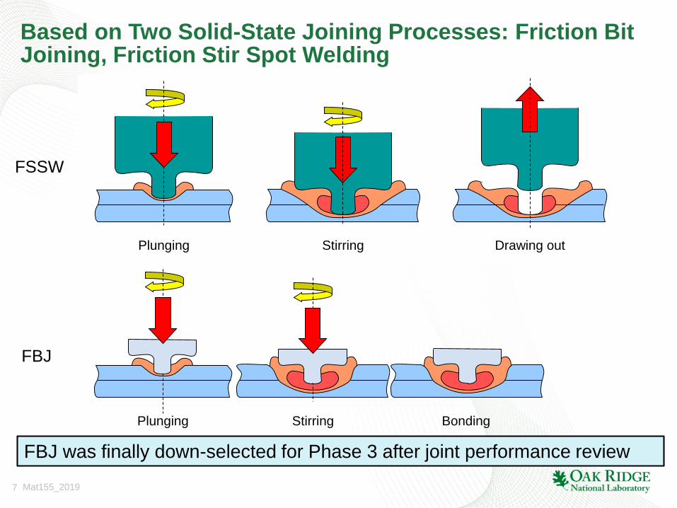
Based on Two Solid-State Joining Processes: Friction Bit Joining, Friction Stir Spot Welding
Plunging Stirring Drawing out
FSSW
FBJ
BondingStirringPlunging
FBJ was finally down-selected for Phase 3 after joint performance review

8 Mat155_2019
R&D Plan: Roles and Responsibilities
High Strength Aluminum
Maximize Weight
Reduction
Part Making Process Impact
Metallurgy Influence on
Joining
Alcoa
Cosma
G-NAC
Honda
Alcoa
Solid-state Joining: FBJ, FSSW
Galvanic Corrosion
Avoidance: Adhesive
Joint Functional Requirements
Friction
Joining
Methods
ORNL, BYU
MegaStir
Dow
L&L
Honda
Process Modeling for FBJ & FSSW
BYU
Metallurgical Joint & Adhesive Model
Spot Weld Equivalency
Process
Modeling
ORNL
ORNL
Structural Modeling: Functional
Performance
Structural Modeling:
Manufacturing Process
Influence
OSU
OSU
Structural
Modeling
Sub-system design &
requirements
Demonstration of sub-system
assembly processing
Sub-system assembly
performance testing
Honda
ORNL
Industry
ORNL
Clear demonstration of multi-material structure joining and performance, increasing potential for application
with implementation challenges & risks quantified.
Demonstration

9 Mat155_2019
Accomplishment: Friction Bit JoiningPassed first go/no-go decision point with FBJ: meet coupon level strength
targets for wide range of material combination and process conditions in FY16
Material
combination
7xxx-1
/DP1180
-GA
7xxx-1
/DP1180
-GA
7xxx-2
/DP1180
-GA
7xxx-2
/DP1180
-GA
7xxx-2
/DP1180
-GA
7xxx-2
/DP1180
-GA
7xxx-2
/DP1180
-GA
7xxx-1/
DP980
7xxx-1/
DP980
Strength
Targets
Thickness (mm) 2.0/1.2 2.0/1.2 2.0/1.2 2.0/1.2 2.0/1.2 2.0/1.2 2.0/1.2 1.6/1.2 2.0/1.2 −
FBJ
design/material1 1 1 2 2 3 4 1 3 −
TSS
(kN)
FBJ-A 10.0(P) 9.7(P) 8.3(P) 9.0(P) 9.9(P) 12.2(P) 13.0(P) 10.3(P) 12.85(P) >5kN
FBJ-2 − − − − − − 10.5(P) 12.9(P)
CTS (kN) 1.91(P) − − − − 2.54(P) 4.33(P) 2.77(P) 2.82(P) >1.5kN
T-Peel (kN) − − − − − 2.17(P) 2.15(P) − 1.63(P) >1.5kN
TSS fatigue
(107) @ 0.75kN
20 Hz, R=0.1
Passed − − − − Passed − − Passed 0.75kN
0
0.5
1
1.5
2
2.5
3
1.E+04 1.E+05 1.E+06 1.E+07 1.E+08
Me
an
fatig
ue
lo
ad
(kN
)
Fatigue life (# of cycle)

10 Mat155_2019
Accomplishment: Cyclic Corrosion Test
• New coupon style tailored to support sealer systems improved assessment activity.
• Significant galvanic corrosion present with exposed fastener head.
• Without adhesive, tight joint fit helped to avoid crevice corrosion (above target).
• With adhesive, inconsistent joint fit & sealer covered degraded adhesion continuity.
• Technique improvements for prepared corrosion coupons will allow for validation of joint durability.
Target: Post CCT strength within 90% of original pre-CCT strength

11 Mat155_2019
Accomplishment: Cyclic Corrosion Test
No Adhesive With AdhesiveBaseline Covered
Edge & Head
Covered
Edge
Post CCT inspection of multi-material coupons showed various levels of corrosion:
E-coat delamination, edge rust, aluminum oxide, gapping between sealer to substrate.
Methodology improvements for sample preparation are still possible as coupons attempt
to recreate production intent processes using sealer materials for isolation.
E-Coat
Delamination
Sealer
Flaw
Aluminum
Oxide
Sealer
Separation
E-Coat
Delam.
Baseline Covered Edge
& Head
Covered
Edge
E-Coat
Delam.
Aluminum
Oxide
E-Coat
Delam.
Edge
Rust

12 Mat155_2019
Accomplishment: Weldbonding of scale-up coupons
• Weldbonding (FBJ with adhesive) was developed on scale-up coupons prior to joining of
sub-component parts.
• Lap shear tensile testing was performed, but joint strength with each adhesive is not
disclosed to public based on IPMP agreement.
• Down-selection of adhesive for Phase 3 was made after review process.
Weldbonding (adhesive A) Weldbonding (adhesive B)
Al Steel SteelAl

13 Mat155_2019
Accomplishment: Thermal expansion mismatch effect in joining dissimilar materials
0
2
4
6
8
10
12
14
16
-500 -400 -300 -200 -100 0 100 200 300 400 500
De
fle
ctio
n (m
m)
Longitudinal distance to the center (mm)
DIC measurement Numerical distortion model
Al
Steel
Panel
Length
Flange
Height
Al Alloy Initial Gap
at center
(mm)
Gap (mm)
at 197°C
Residual
Gap (mm),
DIC
Residual
Gap (mm),
Caliper
Panel ID
Full ½ 6111 0.6 9.09 2.36 - F-H-6111-1
In-situ distortion measurement by Digital Image Correlation (DIC) technique is being developed
to experimentally determine the part dimensional change during paint baking process, to
support and guide numerical modeling development and validation

14 Mat155_2019
Accomplishment: Managing thermal distortion effect with different weld pitches
Pitch=55mmPitch=110mm
Pitch=225mmPitch=450mmPitch=900mm
To quantify the maximum gap and residual gap between Al/steel component under
different pitches and explore options to minimize thermally-induced distortion of Al-
steel sub-assembly due to CTE mismatch
▪ Reducing pitch distance significantly reduces thermal distortion. Overall thermal distortion
ranges from 5mm~14mm.
▪ Pitch distance also influences local stresses in the joint region.

15 Mat155_2019
Accomplishment: Managing thermal distortion effect with different weld pitches
Gap
Heat to 200 ℃ Cool to 20 ℃
The case pitch-55 has very small gap (<30mm) during heating and cooling

16 Mat155_2019
Accomplishment: Refinement of FBJ C-frame design

17 Mat155_2019
Accomplishment: Weld cell fixture design for Phase 3
Coupon fixture & support frames
Demonstration part & fixtures
Coupon fixture & support frames

18 Mat155_2019
Accomplishment: Automated joining bit feed system
Vibratory bowl
(a) (b)
(c) (d)
Joining bit
Air flow
Joining bit
Vibratory bowl
Concept

19 Mat155_2019
Accomplishment: installed robot at weld cellCoupon fixtures, supporting frames, demonstration part and fixtures were shipped to
the industrial partner facility and will be integrated with robot at weld cell.

20 Mat155_2019
Responses to Previous Year Reviewers’ Comments
➢ The chemistry of adhesive used should be presented. An understanding of temperature at the joint interface on adhesive degradability?
There are two adhesive team members (Dow and L&L). Per CRADA requirement, the
chemistry of adhesives are proprietary at this stage. The effects of temperature from
spot joining on adhesives have been examine. They are rather localized within ~1mm
from the bonded region, as revealed in FBJ process model and observation of broken
samples. They have minimal effects on the joint strength and corrosion resistance
from coupon level test.
➢ Predictive capability of microstructure model, and how this effort will integrate into the process.
The microstructure model is under development. It is based on phase transformation
theories high strength steels and Al alloys, therefore applicable to the AHSS and Al
alloys commonly used in auto BIW. The model is informed by experiments. The basic
input of the model are chemistry, microstructure of base metal, and welding thermal
cycles. The predictability of microstructure model will depend on the predictability of
welding process model. In this regards, the process model, microstructure model, and
performance model are integrated in this project.

21 Mat155_2019
Collaborations and Industry Participations
• Roles and Responsibility of Team Members
– ORNL (project lead) : FSSW and FBJ Process Development, Microstructure and property modeling, Adhesive Modeling
– Honda (industry lead): Define industry need and requirement, corrosion test
– Alcoa: Alloy Development
– BYU: FBJ Process Development, Process Modeling
– Cosma: Forming Analysis, Technology Validation at Component Level
– Dow: Adhesive R&D
– G-NAC: Forming Analysis, Technology Validation at Component Level
– L&L: Adhesive R&D
– Mega-Stir: FBJ system
– OSU: Performance Modeling including adhesive bond and thermal distortion

22 Mat155_2019
Remaining Challenges and Barriers
• Managing part distortion due to thermal expansion mismatch of dissimilar material at the component level.
• Ensuring adequate corrosion resistance performance at the component level

23 Mat155_2019
Proposed Future Work
• FY19
– System design for component level joining. April 2019
– System for component joining. June 2019
– Sub-component level joining and demonstration. August 2019
– Sub-component testing and reporting. November 2019
Any proposed future work is subject to change based on funding levels

24 Mat155_2019
Project SummaryRelevance: Address the critical need of dissimilar metal joining for effective use of multi-material
auto-body structure for lightweighting while improving the performance and safety
Approach: Combining solid-state spot welding and adhesive bonding to solve both joining and
corrosion avoidance in use of advanced high-strength steel and 7xxx alloy for auto-
body structures. Mature and validate near-production readiness of the integrated
joining technology. Develop integrated weld process-property-performance model to
assist the process development and multi-material structural optimization.
Technical
Accomplishments
• FBJ: refined joining bit design. passed multi-weld development gate. Applied for
scale-up coupons with and without adhesive. Down-selected for Phase 3
• Adhesives: applied for scale-up coupons. Down-selection was made for Phase 3
• Corrosion performance of FBJ and weldbonded coupons was evaluated. Passed
OEM criteria. Remedies to further improve corrosion performance are suggested.
• Integrated system scale up for component level joining: refined joining bit feed
systems for FBJ. Refined FBJ C-frame design
• Modeling: numerical model for thermal distortion was improved and validated with
experiment results.
• Demonstration part joining: designed weld cell. All coupon fixtures, demonstration
parts and fixtures were prepared and shipped to the industry partner.
Collaborations: An exceptionally strong, strategically selected and vertically-integrated project team
is well suited for both technology development and future technology
commercialization.
Future Plan: Follow the SOPO R&D plan

25 Mat155_2019
Technical Back-up
26 Mat155_2019
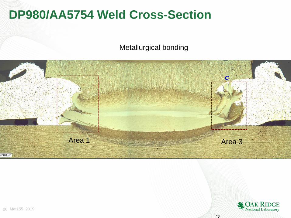
DP980/AA5754 Weld Cross-Section
Area 1 Area 3
Metallurgical bonding
2
C
27 Mat155_2019
Key R&D Matrixes
• Process development and demonstration
– Development and demonstration at a coupon-scale
– Emphasis on demonstration with prototype-scale parts
– Performance metrics at component level
• Joint characterization
– Microstructure, joint defect, mechanical properties
– Corrosion performance
• Model development and validation
– Predict the post-weld microstructure based on process parameters and input microstructure
– Predict quasi-static failure strength
– Predictive model to effectively control or mitigate component distortion and failure due to thermal expansion mismatch of Al and steel

28 Mat155_2019
Research Plan and Major Tasks• Further develop and refine the solid-state joining process and identify process
window/conditions to consistently meet the joint performance and joining cycle time requirement set forth by OEM;
• Combine adhesives with insulator properties to prevent galvanic corrosion between dissimilar metals and improve the structure performance of sub-systems;
• Design, engineer and build a near production ready solid-state spot joining system that can be integrated to an assembly-line welding robot;
• Integrate the solid-state spot joining process with an assembly-line welding robot for prototype scale BIW sub-system joining;
• Thoroughly characterize and evaluate the Al/steel joints against a set of process and performance criteria set forth by the OEM and industry team, at both coupon and sub-system scale;
• Refine and apply an integrated computational weld engineering (ICWE) modeling framework that is capable of accurately predicting the joint performance at both coupon and sub-system levels to assist the joining process development and sub-system design optimization;
• Develop an effective design and joining strategy to minimize the detrimental effects of thermal expansion mismatch between steels and aluminum alloys at sub-system component scale; and
• Demonstrate and validate the developed solid-state joining technology with prototypical BIW sub-systems.
2

29 Mat155_2019
Process selection based on FOM Analysis
FBJ SPR FSSW Ultrasonic
Material
Combination
Steel to Al yes yes coated steel coated steel
Steel to Mg yes difficult TBD coated steel
Steel Grade All AHSS up to DP780 All AHSS All AHSS
Stacks 2T, 3T 2T, 3T 2T 2T
Surface
Requirementno restriction no restriction Zn coating
Zn coating, some
cleaning
Bonding MechanismMetallurgical +
MechnicalMechanical
Brazing or
Metallurgical
Brazing, or
metallurgical
Lap shear strength
(N)
Steel to Al 6300 - 8100 5000 - 5500 2500 - 3500 ~3000
Steel to Mg ~5400 cracking N/A 4200
Z load (N) ~ 9000 20,000 or higher TBD ~ 2000
Process Time (sec) 1.5 - 2 < 1 <4 1.2 - 2
Weld bonding Feasible yes Difficult TBD
Consumable Bit Yes Yes
Cost Comparable to SPR low
Nonconsumerable
ToolYes Yes
Cost High High
Machine cost comparable comparable comparable Potentially high
Machine
automationFeasible Yes demonstrated Feasible

30 Mat155_2019
Coupon-level performance target metrics based on input from industry team members
Steel
Baseline
Steel-Al
spot weld
Steel-Al
Adhesive
Steel-Al
Combined
Material Top 1500P 7xxx Al 7xxx Al 7xxx Al
Material Bottom DP1180 DP1180 DP1180 DP1180
Tensile shear strength >18kN >5kN >10kN >15kN
Cross tension strength >5kN >1.5kN >3kN >4.5kN
CTS/TSS 0.28 0.3 0.3 0.3
Peel strength >2kN >1.5kN Measure Measure
Peel/TSS 0.12 0.3 Measure Measure
TSS Fatigue @ 107 cycles 0.75kN 0.75kN measure 0.75kN

31 Mat155_2019
ID Task
Mode
Task Name Duration Start Finish Predecessors Resource Names
1
2
3 Frame Design 26 days Mon 1/21/19Mon 2/25/19 Lee Machine,AMP
4 Frame Final Design 10 days Tue 2/26/19 Mon 3/11/193 AMP,HRA,Lee Machine,MegaStir
5 Component Specs 16 days Mon 1/21/19Mon 2/11/19 MegaStir,Lee Machine,AMP
6 Component Package 10 days Tue 2/12/19 Mon 2/25/19
5 AMP,Lee Machine,MegaStir
7 Feed System 16 days Mon 1/21/19Mon 2/11/19 AMP
8 Feed System Design Update
25 days Tue 2/12/19 Mon 3/18/19
7 AMP
9 Feed system fabrication
30 days Tue 2/26/19 Mon 4/8/19 8 AMP
10 Honda Fab Review 26 days Mon 2/11/19Mon 3/18/19 HRA
11 Frame "Go" Fabrication
30 days Tue 3/12/19 Mon 4/22/19
4 HRA
12 Components/ Feed system/ load cell "go"
4 days Tue 4/23/19 Fri 4/26/19 11 BYU,Lee Machine,MegaStir
13 Machine Assembly 30 days Tue 4/23/19 Mon 6/3/19 9,11 MegaStir,AMP,Lee Machine
14 Assembly machine& Robot
11 days Tue 6/4/19 Tue 6/18/19 13 Lee Machine,MegaStir
15 Machine Robot teach coupon demonstration
30 days Wed 6/19/19
Tue 7/30/19 14 Lee Machine,MegaStir
16 Precustomer runoff HRA parts
10 days Wed 7/31/19
Tue 8/13/19 15 BYU,MegaStir
17 Machine Demonstration
6 days Wed 8/14/19
Wed 8/21/19
16 BYU,Lee Machine,MegaStir
18 Performance Evaluation Validation
12 wks Thu 8/22/19 Wed 11/13/19
17 MegaStir
19
20 FBJ bit production 60 days Fri 2/22/19 Thu 5/16/19 MegaStir
Lee Machine,AMP
AMP,HRA,Lee Machine,MegaStir
MegaStir,Lee Machine,AMP
AMP,Lee Machine,MegaStir
AMP
AMP
AMP
HRA
HRA
BYU,Lee Machine,MegaStir
MegaStir,AMP,Lee Machine
Lee Machine,MegaStir
Lee Machine,MegaStir
BYU,MegaStir
BYU,Lee Machine,MegaStir
MegaStir
MegaStir
Jan Feb Mar Apr May Jun Jul Aug Sep Oct Nov Dec
Qtr 1, 2019 Qtr 2, 2019 Qtr 3, 2019 Qtr 4, 2019
Task
Split
Milestone
Summary
Project Summary
Inactive Task
Inactive Milestone
Inactive Summary
Manual Task
Duration-only
Manual Summary Rollup
Manual Summary
Start-only
Finish-only
External Tasks
External Milestone
Deadline
Progress
Manual Progress
Page 1
Project: Phase 3 timeline.mpp
Date: Thu 3/28/19