Embed Size (px)
Citation preview
8/2/2019 Solid Works 2006 Fundamentals
http://slidepdf.com/reader/full/solid-works-2006-fundamentals 1/50
Solidworks 2006 Fundamentals
Version 1- May07 Written by Dickson Sham
A- 1
Solidworks 2006
FundamentalsInfrastructure
Sketch
Solid FeaturesSurfaces
Assembly Design
2D Drawing
Design Table & Equation
8/2/2019 Solid Works 2006 Fundamentals
http://slidepdf.com/reader/full/solid-works-2006-fundamentals 2/50
Solidworks 2006 Fundamentals
Version 1- May07 Written by Dickson Sham
A- 2
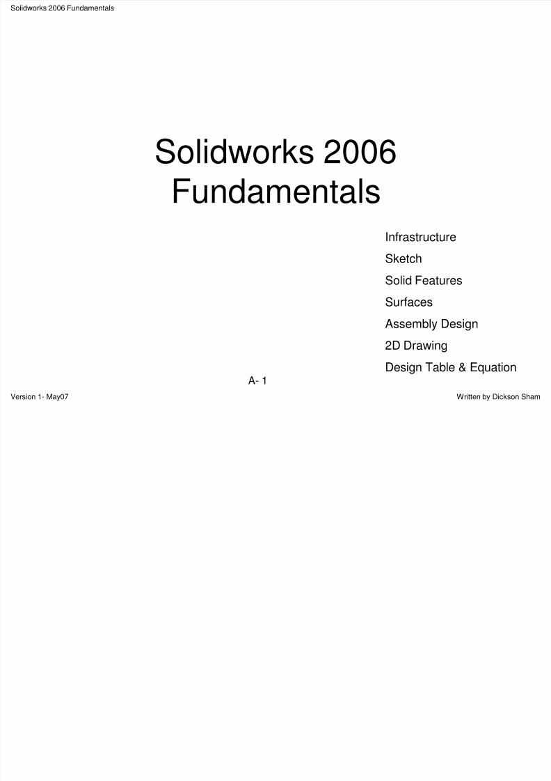
User InterfaceGeneral
File Name
SpecificationTree (allfeatures storedin historical
order)
Dimmed features(hidden)
Lights on model
Folder for solids(one visible inside)
Folder for surfaces(3 hidden inside)
Global coordinate (neverbe changed)
Geometry area/ Working area
Menu bar (allcommands)
Feature Manager (toswitch the layout oftoolbars)
Toolbars(commonly-usedcommands only)
8/2/2019 Solid Works 2006 Fundamentals
http://slidepdf.com/reader/full/solid-works-2006-fundamentals 3/50
Solidworks 2006 Fundamentals
Version 1- May07 Written by Dickson Sham
A- 3
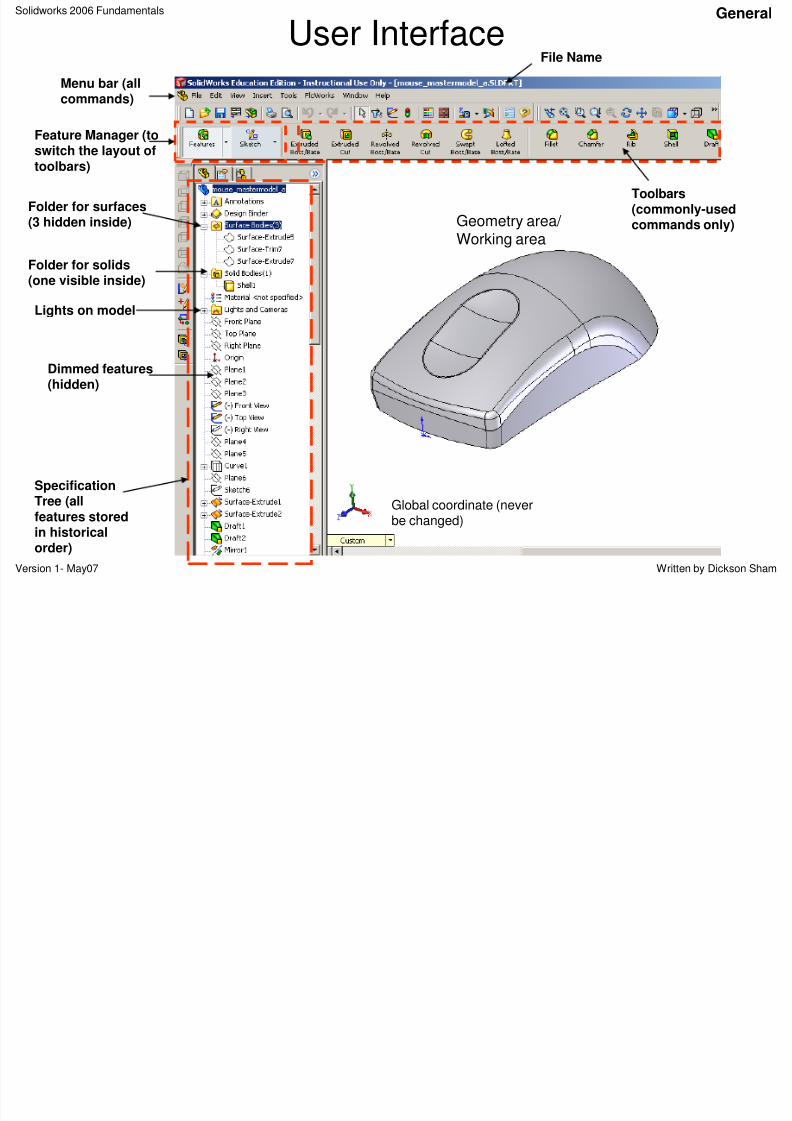
Type of DocumentsThe common documents are:
A) A part document (. sldprt) , which contains
information how the model is built
B) An assembly document (.sldasm), whichcontains the relative positions of components
C) A drawing document (.slddrw), which can be apart drawing or an assembly drawing
C
General
A
B
8/2/2019 Solid Works 2006 Fundamentals
http://slidepdf.com/reader/full/solid-works-2006-fundamentals 4/50
Solidworks 2006 Fundamentals
Version 1- May07 Written by Dickson Sham
A- 4
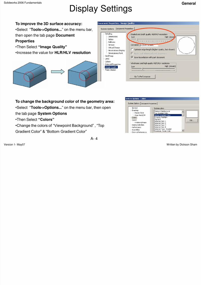
Display Settings
To improve the 3D surface accuracy:
•Select “Tools->Options...” on the menu bar,
then open the tab page Document
Properties
•Then Select “Image Quality”
•Increase the value for HLR/HLV resolution
To change the background color of the geometry area:
•Select “Tools->Options...” on the menu bar, then open
the tab page System Options
•Then Select “Colors”
•Change the colors of “Viewpoint Background” , “Top
Gradient Color” & “Bottom Gradient Color”
General
8/2/2019 Solid Works 2006 Fundamentals
http://slidepdf.com/reader/full/solid-works-2006-fundamentals 5/50
Solidworks 2006 Fundamentals
Version 1- May07 Written by Dickson Sham
A- 5
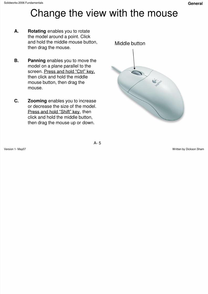
Change the view with the mouse
A. Rotating enables you to rotate
the model around a point. Clickand hold the middle mouse button,then drag the mouse.
B. Panning enables you to move themodel on a plane parallel to the
screen. Press and hold “Ctrl” key,then click and hold the middlemouse button, then drag themouse.
C. Zooming enables you to increase
or decrease the size of the model.Press and hold “Shift” key, thenclick and hold the middle button,then drag the mouse up or down.
Middle button
General
8/2/2019 Solid Works 2006 Fundamentals
http://slidepdf.com/reader/full/solid-works-2006-fundamentals 6/50
Solidworks 2006 Fundamentals
Version 1- May07 Written by Dickson Sham
A- 6
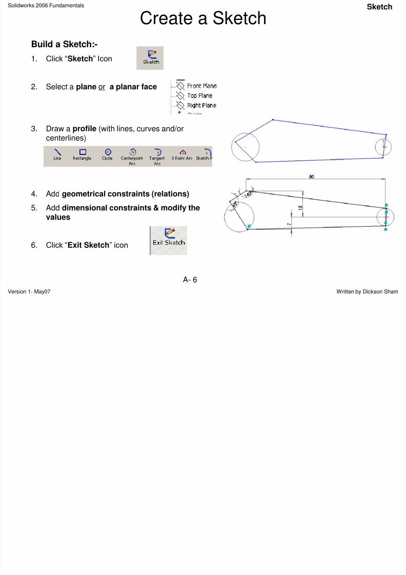
Create a Sketch
Build a Sketch:-
1. Click “Sketch” Icon
2. Select a plane or a planar face
3. Draw a profile (with lines, curves and/or
centerlines)
4. Add geometrical constraints (relations)
5. Add dimensional constraints & modify thevalues
6. Click “Exit Sketch” icon
Sketch
8/2/2019 Solid Works 2006 Fundamentals
http://slidepdf.com/reader/full/solid-works-2006-fundamentals 7/50
Solidworks 2006 Fundamentals
Version 1- May07 Written by Dickson Sham
A- 7
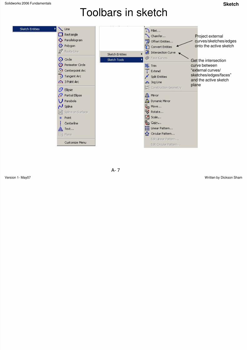
Toolbars in sketch
Project external
curves/sketches/edgesonto the active sketch
Get the intersectioncurve between“external curves/
sketches/edges/faces”
and the active sketch
plane
Sketch
8/2/2019 Solid Works 2006 Fundamentals
http://slidepdf.com/reader/full/solid-works-2006-fundamentals 8/50
Solidworks 2006 Fundamentals
Version 1- May07 Written by Dickson Sham
A- 8
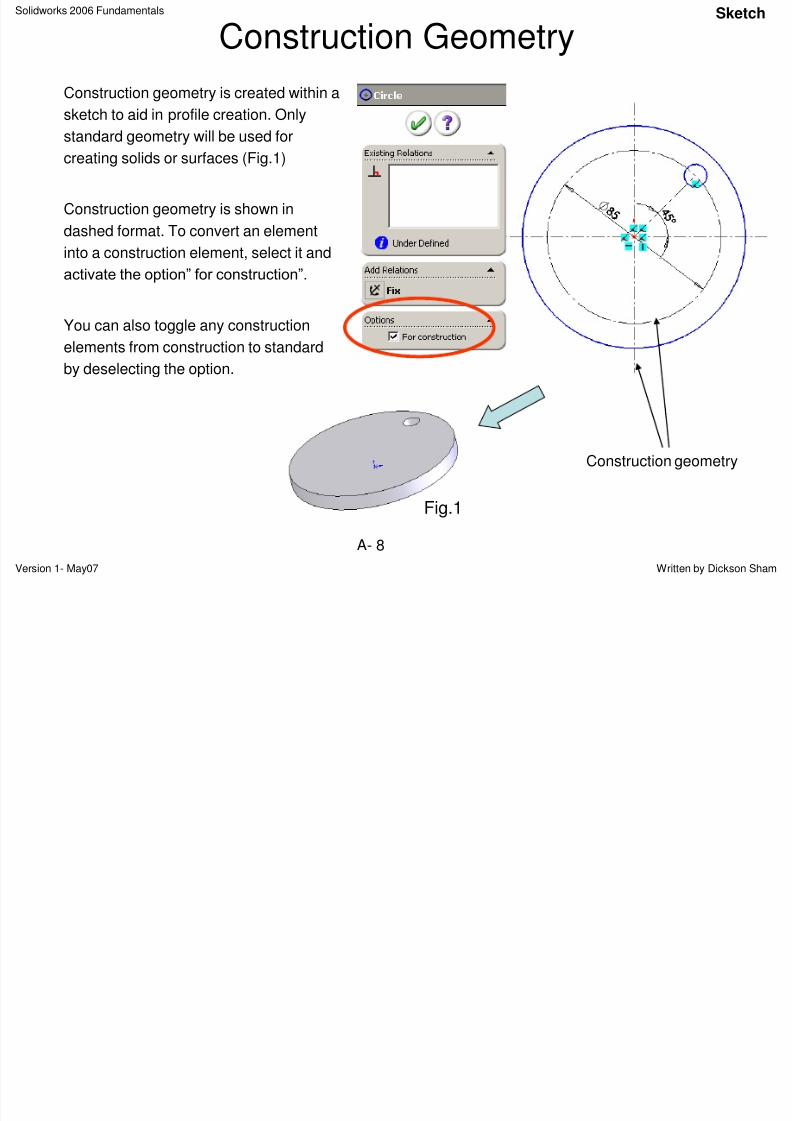
Construction Geometry
Construction geometry is created within a
sketch to aid in profile creation. Only
standard geometry will be used forcreating solids or surfaces (Fig.1)
Construction geometry is shown in
dashed format. To convert an element
into a construction element, select it and
activate the option” for construction”.
You can also toggle any construction
elements from construction to standard
by deselecting the option.
Construction geometry
Fig.1
Sketch
8/2/2019 Solid Works 2006 Fundamentals
http://slidepdf.com/reader/full/solid-works-2006-fundamentals 9/50
Solidworks 2006 Fundamentals
Version 1- May07 Written by Dickson Sham
A- 9
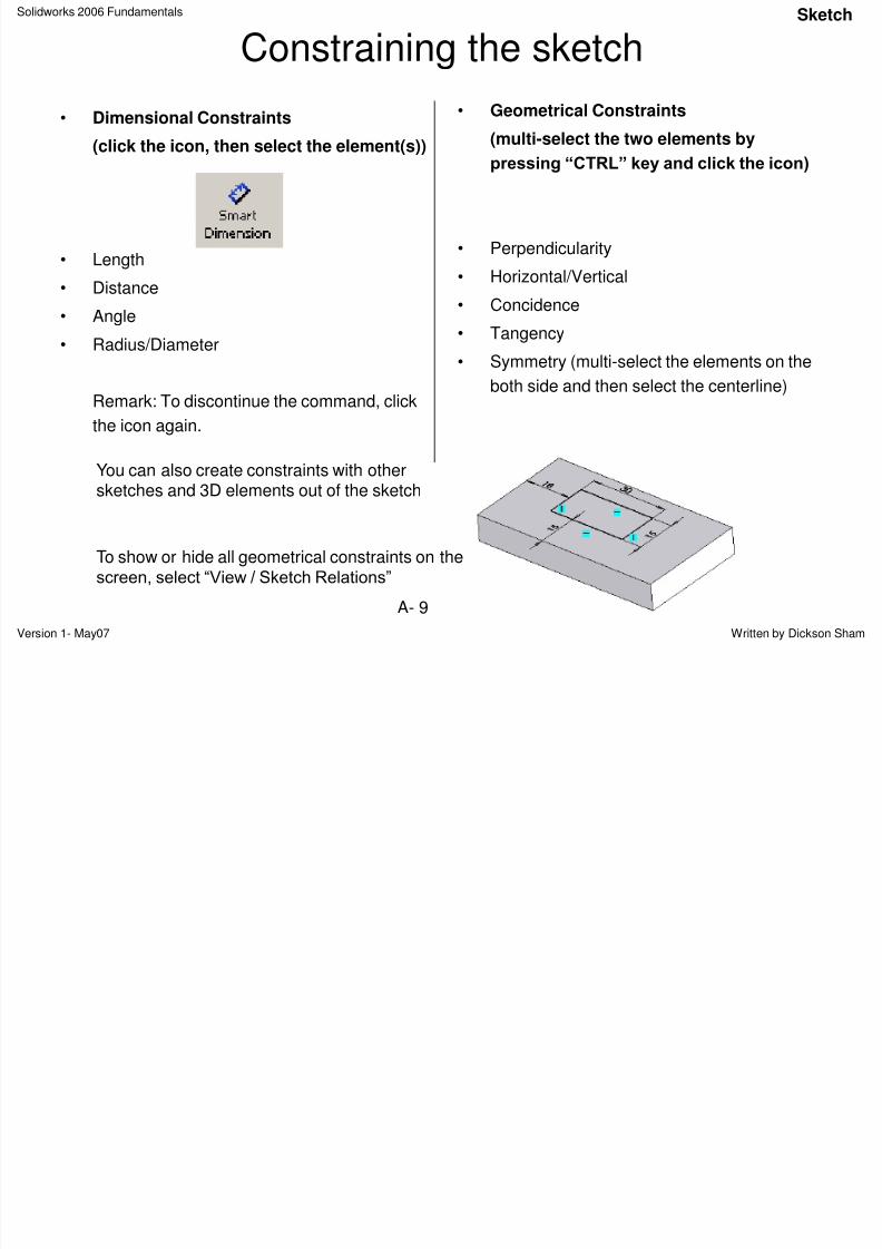
Constraining the sketch
• Dimensional Constraints
(click the icon, then select the element(s))
• Length
• Distance
• Angle
• Radius/Diameter
Remark: To discontinue the command, click
the icon again.
• Geometrical Constraints
(multi-select the two elements by
pressing “CTRL” key and click the icon)
• Perpendicularity
• Horizontal/Vertical
• Concidence
• Tangency
• Symmetry (multi-select the elements on the
both side and then select the centerline)
You can also create constraints with othersketches and 3D elements out of the sketch
To show or hide all geometrical constraints on thescreen, select “View / Sketch Relations”
Sketch
8/2/2019 Solid Works 2006 Fundamentals
http://slidepdf.com/reader/full/solid-works-2006-fundamentals 10/50
Solidworks 2006 Fundamentals
Version 1- May07 Written by Dickson ShamA- 10
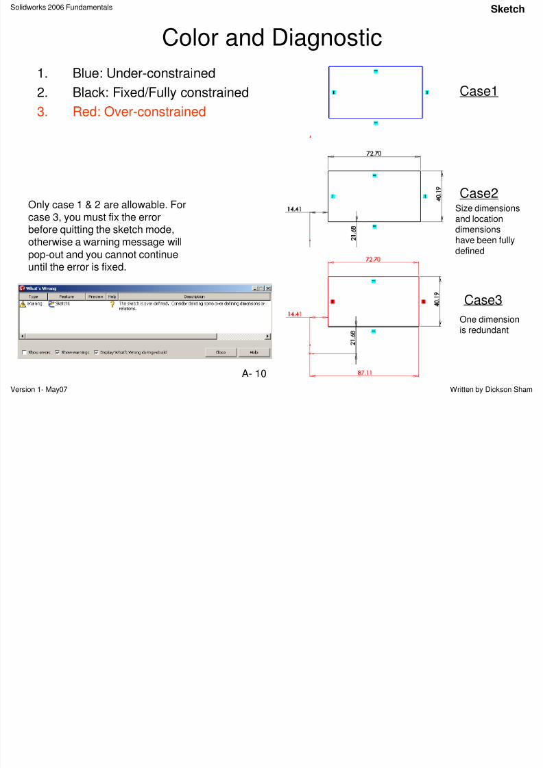
Color and Diagnostic
1. Blue: Under-constrained
2. Black: Fixed/Fully constrained3. Red: Over-constrained
Only case 1 & 2 are allowable. Forcase 3, you must fix the errorbefore quitting the sketch mode,otherwise a warning message willpop-out and you cannot continueuntil the error is fixed.
Case1
Case2
Case3
Size dimensionsand locationdimensionshave been fullydefined
One dimensionis redundant
Sketch
8/2/2019 Solid Works 2006 Fundamentals
http://slidepdf.com/reader/full/solid-works-2006-fundamentals 11/50
Solidworks 2006 Fundamentals
Version 1- May07 Written by Dickson ShamA- 11
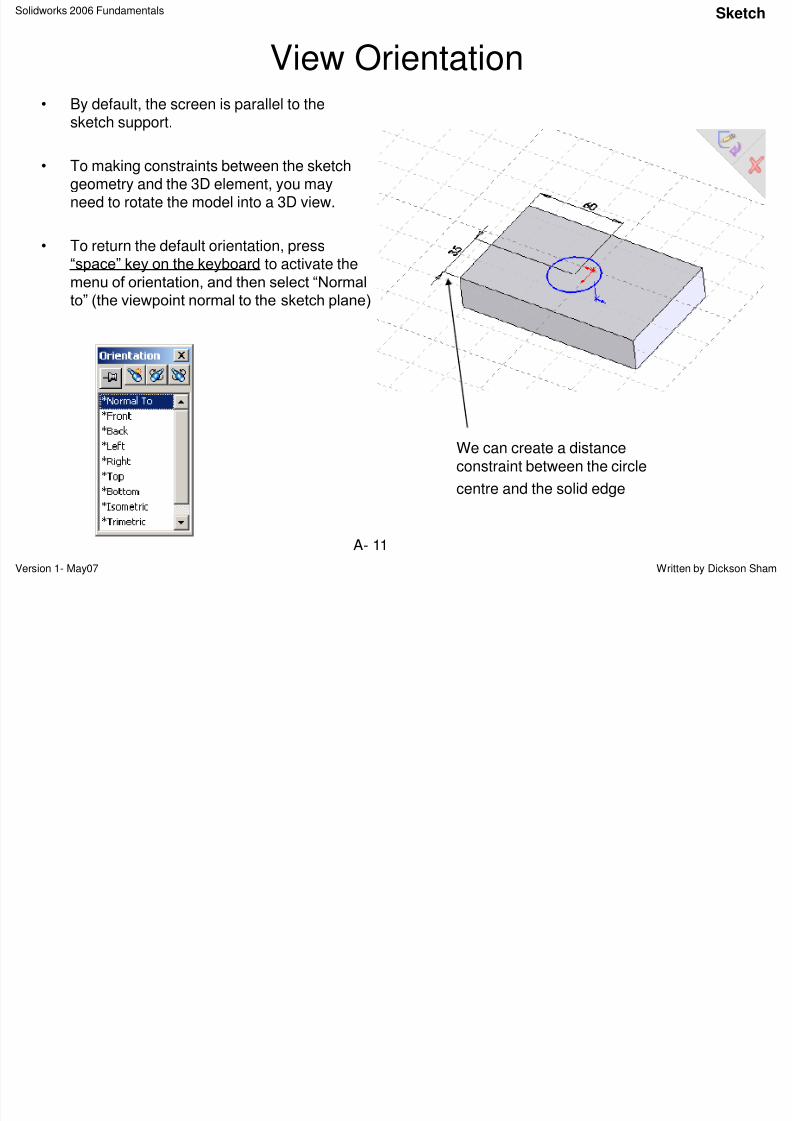
View Orientation• By default, the screen is parallel to the
sketch support.
• To making constraints between the sketchgeometry and the 3D element, you mayneed to rotate the model into a 3D view.
• To return the default orientation, press“space” key on the keyboard to activate themenu of orientation, and then select “Normal
to” (the viewpoint normal to the sketch plane)
We can create a distanceconstraint between the circle
centre and the solid edge
Sketch
S lid k F d l
8/2/2019 Solid Works 2006 Fundamentals
http://slidepdf.com/reader/full/solid-works-2006-fundamentals 12/50
Solidworks 2006 Fundamentals
Version 1- May07 Written by Dickson ShamA- 12
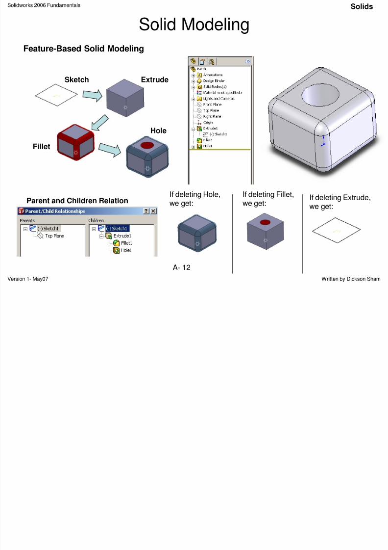
Solid Modeling
Feature-Based Solid Modeling
Sketch Extrude
Fillet
Hole
Parent and Children Relation
If deleting Hole,
we get:
If deleting Fillet,
we get:If deleting Extrude,we get:
Solids
S lid k 2006 F d t l S
8/2/2019 Solid Works 2006 Fundamentals
http://slidepdf.com/reader/full/solid-works-2006-fundamentals 13/50
Solidworks 2006 Fundamentals
Version 1- May07 Written by Dickson ShamA- 13
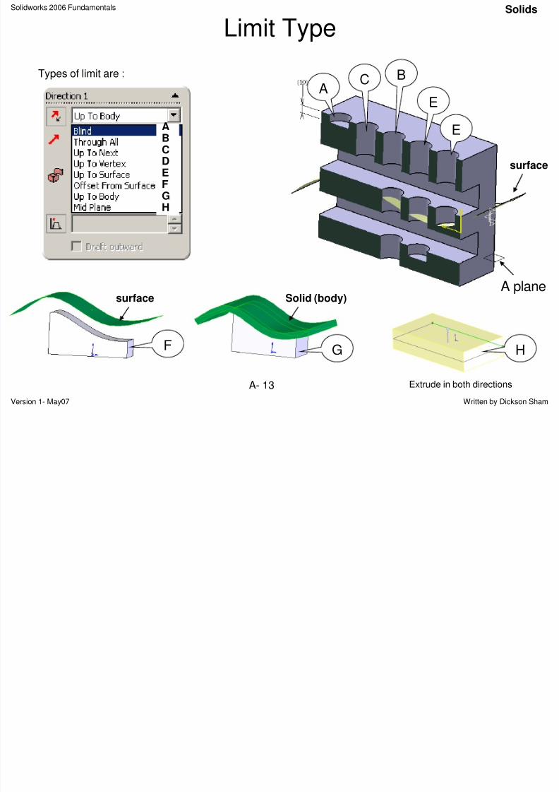
Limit Type
Types of limit are :
AC B
E
E
A plane
surface
ABCDEF
GH
surface
F
Solid (body)
G H
Extrude in both directions
Solids
S lid k 2006 F d t l S lid
8/2/2019 Solid Works 2006 Fundamentals
http://slidepdf.com/reader/full/solid-works-2006-fundamentals 14/50
Solidworks 2006 Fundamentals
Version 1- May07 Written by Dickson ShamA- 14
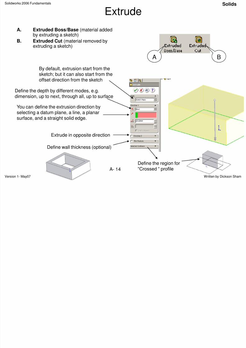
Extrude
A. Extruded Boss/Base (material addedby extruding a sketch)
B. Extruded Cut (material removed byextruding a sketch)
A B
You can define the extrusion direction byselecting a datum plane, a line, a planarsurface, and a straight solid edge.
Extrude in opposite direction
Define wall thickness (optional)
Define the depth by different modes, e.g.dimension, up to next, through all, up to surface
By default, extrusion start from thesketch; but it can also start from theoffset direction from the sketch
Define the region for
“Crossed “ profile
Solids
Solidworks 2006 Fundamentals S lid
8/2/2019 Solid Works 2006 Fundamentals
http://slidepdf.com/reader/full/solid-works-2006-fundamentals 15/50
Solidworks 2006 Fundamentals
Version 1- May07 Written by Dickson ShamA- 15
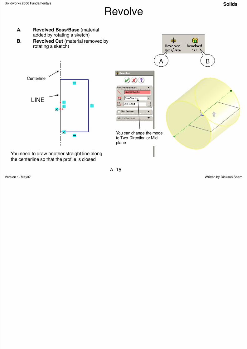
Revolve
A. Revolved Boss/Base (materialadded by rotating a sketch)
B. Revolved Cut (material removed byrotating a sketch)
A B
You need to draw another straight line alongthe centerline so that the profile is closed
Centerline
LINE
You can change the modeto Two-Direction or Mid-plane
Solids
Solidworks 2006 Fundamentals S lid
8/2/2019 Solid Works 2006 Fundamentals
http://slidepdf.com/reader/full/solid-works-2006-fundamentals 16/50
Solidworks 2006 Fundamentals
Version 1- May07 Written by Dickson ShamA- 16
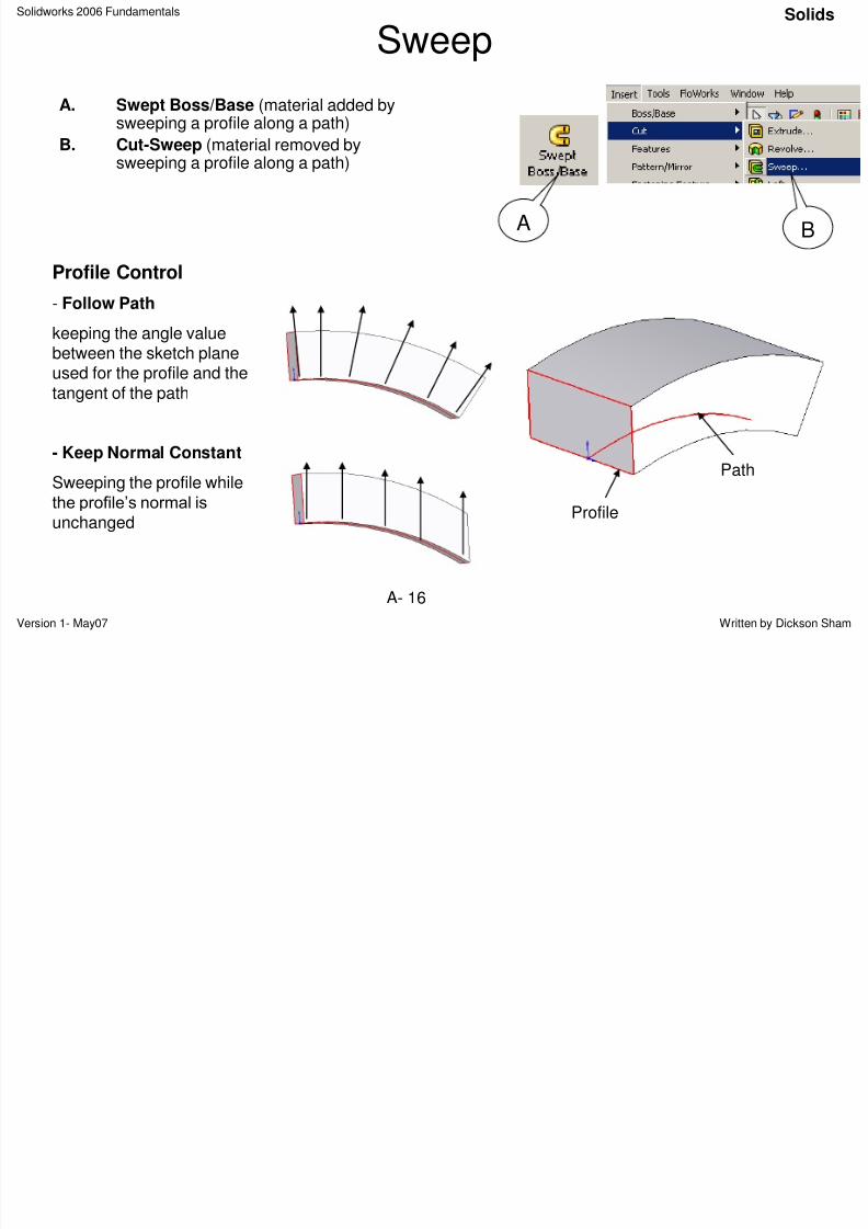
Sweep
A. Swept Boss/Base (material added bysweeping a profile along a path)
B. Cut-Sweep (material removed bysweeping a profile along a path)
A B
Path
Profile
Profile Control
- Follow Path
keeping the angle valuebetween the sketch planeused for the profile and thetangent of the path
- Keep Normal Constant
Sweeping the profile whilethe profile‟s normal is
unchanged
Solids
Solidworks 2006 Fundamentals Solids
8/2/2019 Solid Works 2006 Fundamentals
http://slidepdf.com/reader/full/solid-works-2006-fundamentals 17/50
Solidworks 2006 Fundamentals
Version 1- May07 Written by Dickson ShamA- 17
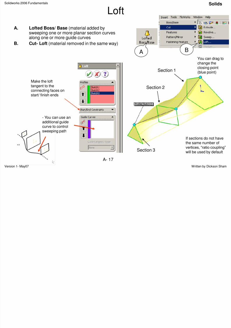
Loft
A. Lofted Boss/ Base (material added bysweeping one or more planar section curvesalong one or more guide curves
B. Cut- Loft (material removed in the same way)
A B
Section 2
Section 1
Section 3
If sections do not havethe same number ofvertices, “ratio coupling”
will be used by default
You can drag tochange theclosing point(blue point)
- You can use an
additional guidecurve to controlsweeping path
Make the lofttangent to theconnecting faces onstart/ finish ends
Solids
Solidworks 2006 Fundamentals Solids
8/2/2019 Solid Works 2006 Fundamentals
http://slidepdf.com/reader/full/solid-works-2006-fundamentals 18/50
Solidworks 2006 Fundamentals
Version 1- May07 Written by Dickson ShamA- 18
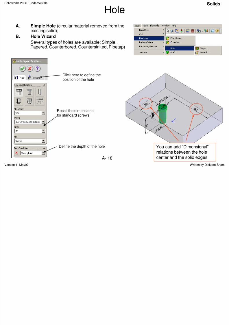
Hole
A. Simple Hole (circular material removed from theexisting solid);
B. Hole Wizard
Several types of holes are available: Simple,Tapered, Counterbored, Countersinked, Pipetap)
You can add “Dimensional”
relations between the hole
center and the solid edges
Recall the dimensionsfor standard screws
Define the depth of the hole
Click here to define the
position of the hole
Solids
Solidworks 2006 Fundamentals Solids
8/2/2019 Solid Works 2006 Fundamentals
http://slidepdf.com/reader/full/solid-works-2006-fundamentals 19/50
Solidworks 2006 Fundamentals
Version 1- May07 Written by Dickson ShamA- 19
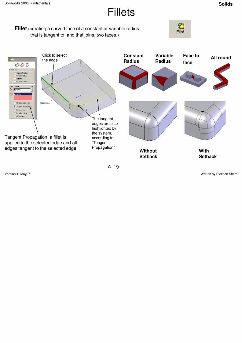
Fillets
Fillet (creating a curved face of a constant or variable radius
that is tangent to, and that joins, two faces.)
ConstantRadius
VariableRadius
Face to
faceAll round
Tangent Propagation: a fillet isapplied to the selected edge and alledges tangent to the selected edge
WithoutSetback
WithSetback
Solids
Click to selectthe edge
The tangentedges are alsohighlighted bythe system,according to“Tangent
Propagation”
Solidworks 2006 Fundamentals
Solids
8/2/2019 Solid Works 2006 Fundamentals
http://slidepdf.com/reader/full/solid-works-2006-fundamentals 20/50
Solidworks 2006 Fundamentals
Version 1- May07 Written by Dickson ShamA- 20
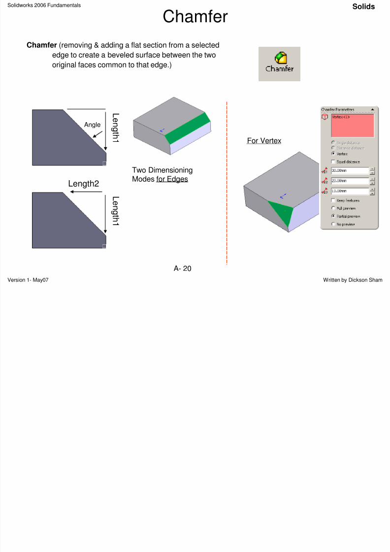
Chamfer
Chamfer (removing & adding a flat section from a selected
edge to create a beveled surface between the two
original faces common to that edge.)
Two DimensioningModes for Edges
L en g
t h 1
Angle
L
en g t h 1
Length2
For Vertex
Solids
Solidworks 2006 Fundamentals Solids
8/2/2019 Solid Works 2006 Fundamentals
http://slidepdf.com/reader/full/solid-works-2006-fundamentals 21/50
Solidworks 2006 Fundamentals
Version 1- May07 Written by Dickson ShamA- 21
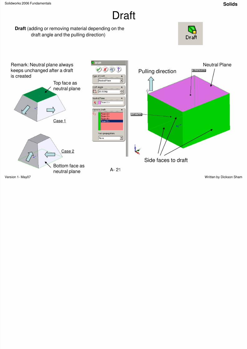
DraftDraft (adding or removing material depending on the
draft angle and the pulling direction)
Neutral Plane
Side faces to draft
Pulling direction
Remark: Neutral plane alwayskeeps unchanged after a draftis created
Top face asneutral plane
Bottom face as
neutral plane
Solids
Case 1
Case 2
Solidworks 2006 Fundamentals Solids
8/2/2019 Solid Works 2006 Fundamentals
http://slidepdf.com/reader/full/solid-works-2006-fundamentals 22/50
Solidworks 2006 Fundamentals
Version 1- May07 Written by Dickson ShamA- 22
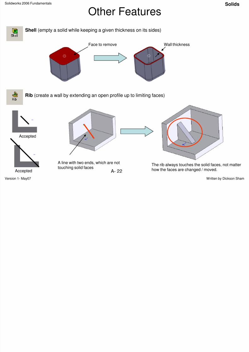
Other Features
Shell (empty a solid while keeping a given thickness on its sides)
Face to remove
Rib (create a wall by extending an open profile up to limiting faces)
A line with two ends, which are nottouching solid faces
The rib always touches the solid faces, not matterhow the faces are changed / moved.
Solids
Wall thickness
Accepted
Accepted
Solidworks 2006 Fundamentals Reference Geometry
8/2/2019 Solid Works 2006 Fundamentals
http://slidepdf.com/reader/full/solid-works-2006-fundamentals 23/50
Version 1- May07 Written by Dickson ShamA- 23
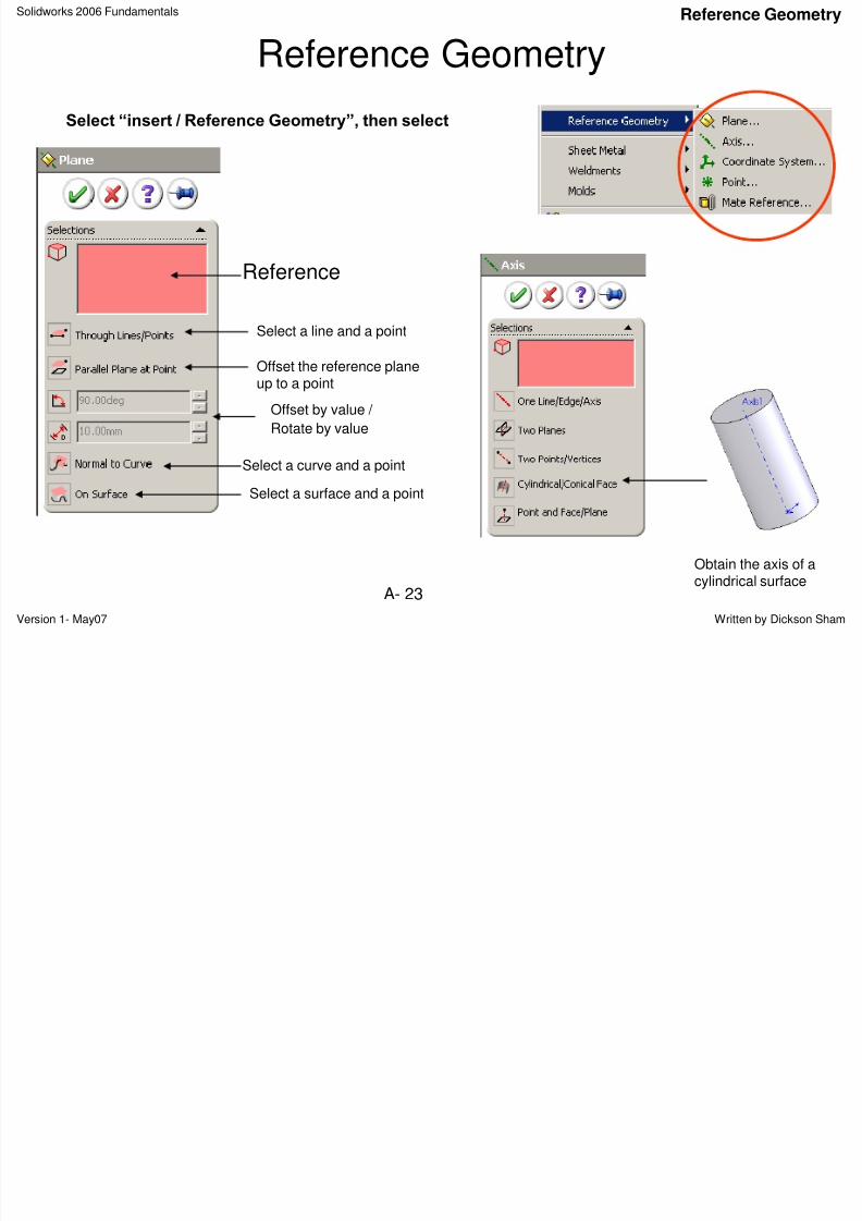
Reference Geometry
Select “insert / Reference Geometry”, then select
Reference
Select a curve and a point
Select a surface and a point
Offset the reference planeup to a point
Select a line and a point
Offset by value /
Rotate by value
Obtain the axis of acylindrical surface
Reference Geometry
Solidworks 2006 Fundamentals Curves
8/2/2019 Solid Works 2006 Fundamentals
http://slidepdf.com/reader/full/solid-works-2006-fundamentals 24/50
Version 1- May07 Written by Dickson ShamA- 24
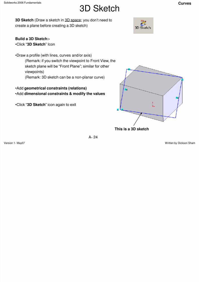
3D Sketch3D Sketch (Draw a sketch in 3D space; you don‟t need to
create a plane before creating a 3D sketch)
Build a 3D Sketch:-
•Click “3D Sketch” Icon
•Draw a profile (with lines, curves and/or axis)
(Remark: if you switch the viewpoint to Front View, the
sketch plane will be “Front Plane”; similar for other
viewpoints)
(Remark: 3D sketch can be a non-planar curve)
•Add geometrical constraints (relations)
•Add dimensional constraints & modify the values
•Click “3D Sketch” icon again to exit
Curves
This is a 3D sketch
Solidworks 2006 Fundamentals Curves
8/2/2019 Solid Works 2006 Fundamentals
http://slidepdf.com/reader/full/solid-works-2006-fundamentals 25/50
Version 1- May07 Written by Dickson ShamA- 25
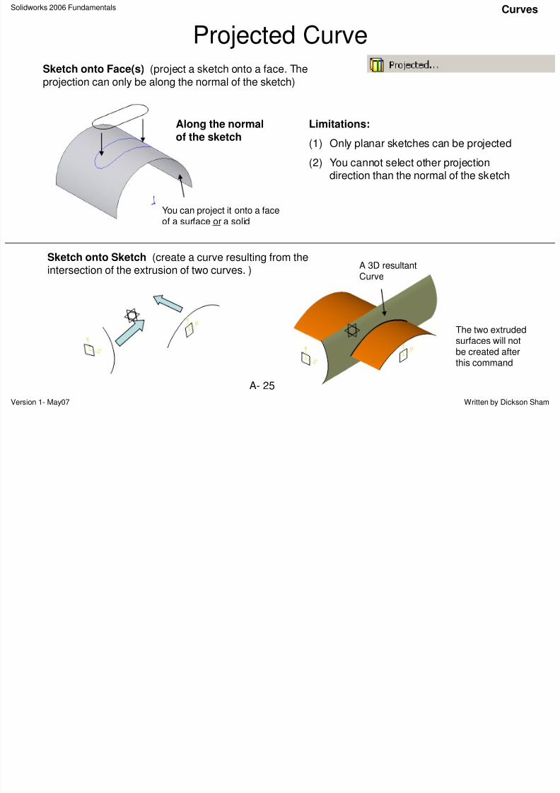
Projected CurveSketch onto Face(s) (project a sketch onto a face. Theprojection can only be along the normal of the sketch)
Along the normalof the sketch
Limitations:
(1) Only planar sketches can be projected
(2) You cannot select other projectiondirection than the normal of the sketch
You can project it onto a faceof a surface or a solid
Sketch onto Sketch (create a curve resulting from theintersection of the extrusion of two curves. )
A 3D resultantCurve
The two extrudedsurfaces will notbe created afterthis command
Curves
Solidworks 2006 Fundamentals Curves
8/2/2019 Solid Works 2006 Fundamentals
http://slidepdf.com/reader/full/solid-works-2006-fundamentals 26/50
Version 1- May07 Written by Dickson ShamA- 26
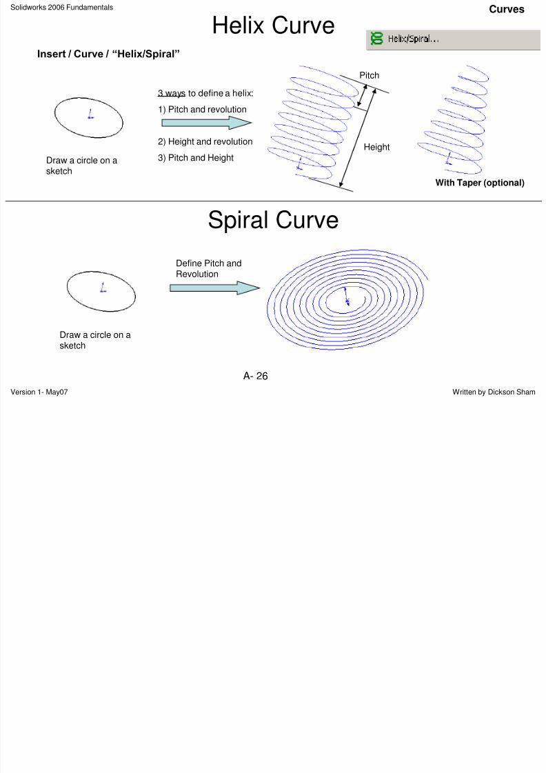
Helix CurveInsert / Curve / “Helix/Spiral”
Draw a circle on asketch
Curves
Spiral Curve
3 ways to define a helix:1) Pitch and revolution
2) Height and revolution
3) Pitch and Height
Pitch
Height
With Taper (optional)
Draw a circle on asketch
Define Pitch andRevolution
Solidworks 2006 Fundamentals Curves
8/2/2019 Solid Works 2006 Fundamentals
http://slidepdf.com/reader/full/solid-works-2006-fundamentals 27/50
Version 1- May07 Written by Dickson ShamA- 27
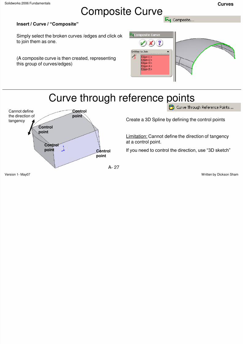
Composite CurveInsert / Curve / “Composite”
Curves
Curve through reference points
Controlpoint
Controlpoint
Controlpoint
Controlpoint
Create a 3D Spline by defining the control points
Limitation: Cannot define the direction of tangencyat a control point.
If you need to control the direction, use “3D sketch”
Cannot definethe direction oftangency
Simply select the broken curves /edges and click ok
to join them as one.
(A composite curve is then created, representingthis group of curves/edges)
Solidworks 2006 Fundamentals Surfaces
8/2/2019 Solid Works 2006 Fundamentals
http://slidepdf.com/reader/full/solid-works-2006-fundamentals 28/50
Version 1- May07 Written by Dickson ShamA- 28
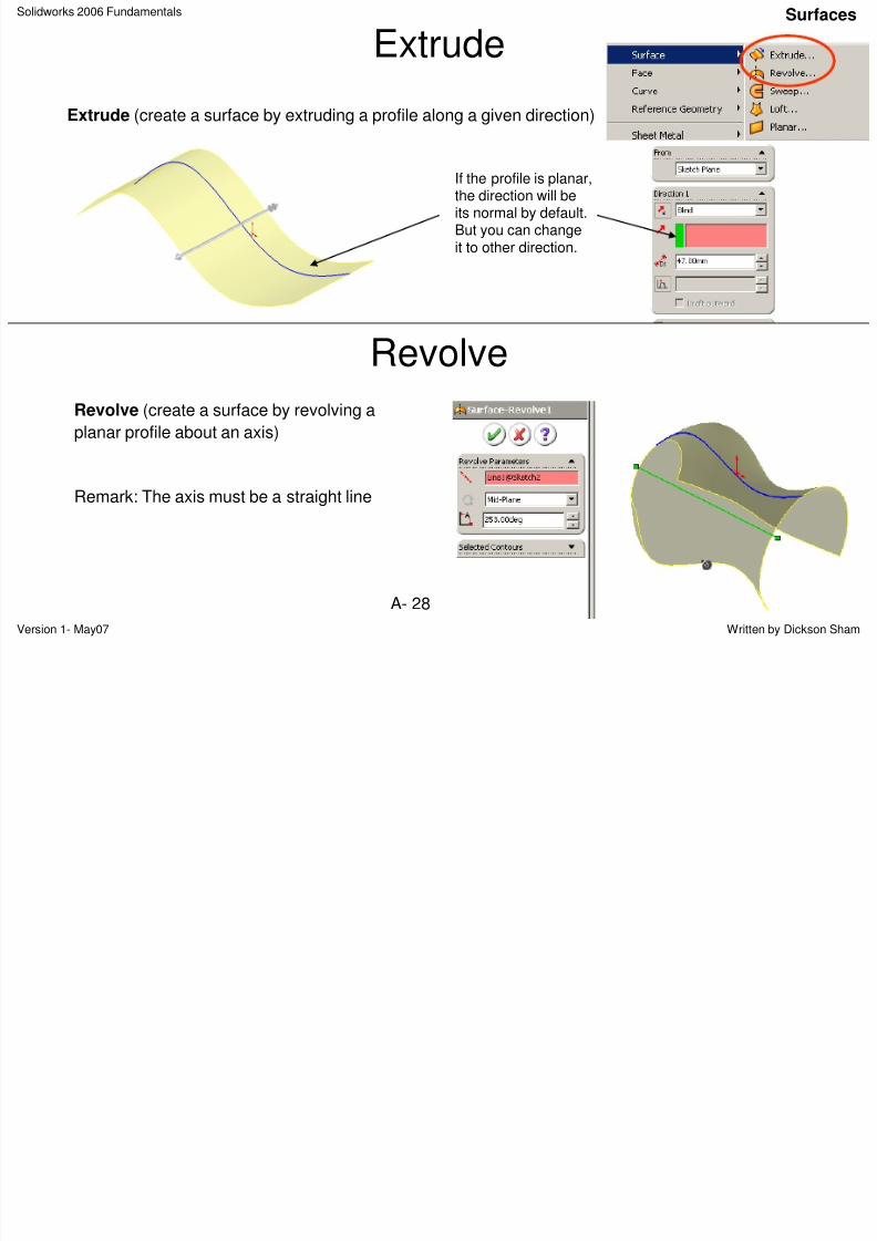
Extrude
Extrude (create a surface by extruding a profile along a given direction)
If the profile is planar,the direction will beits normal by default.But you can changeit to other direction.
Revolve
Revolve (create a surface by revolving a
planar profile about an axis)
Remark: The axis must be a straight line
Surfaces
Solidworks 2006 Fundamentals Surfaces
8/2/2019 Solid Works 2006 Fundamentals
http://slidepdf.com/reader/full/solid-works-2006-fundamentals 29/50
Version 1- May07 Written by Dickson ShamA- 29
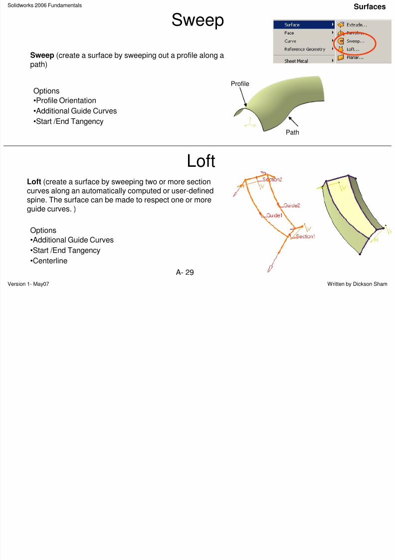
Sweep
Sweep (create a surface by sweeping out a profile along apath)
Options
•Profile Orientation
•Additional Guide Curves
•Start /End Tangency
Profile
Path
Loft (create a surface by sweeping two or more sectioncurves along an automatically computed or user-definedspine. The surface can be made to respect one or more
guide curves. )
Loft
Options
•Additional Guide Curves
•Start /End Tangency
•Centerline
Solidworks 2006 Fundamentals Surfaces
8/2/2019 Solid Works 2006 Fundamentals
http://slidepdf.com/reader/full/solid-works-2006-fundamentals 30/50
Version 1- May07 Written by Dickson ShamA- 30
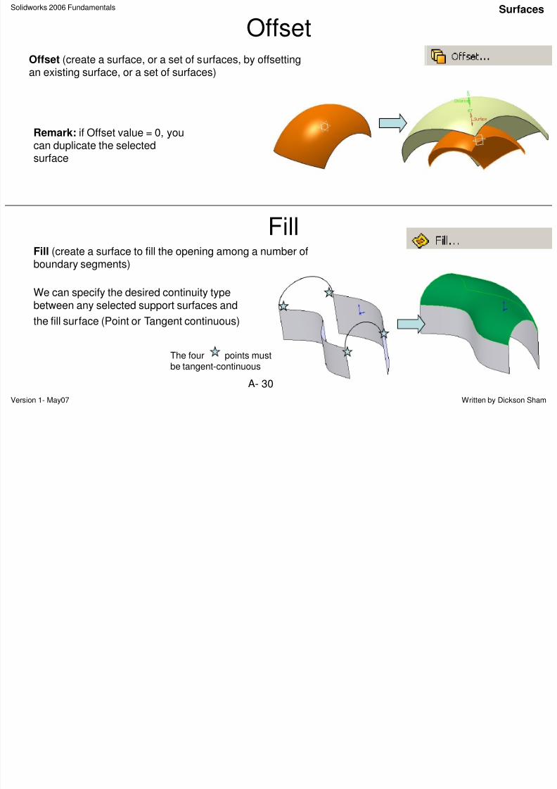
Offset
Fill (create a surface to fill the opening among a number ofboundary segments)
Offset (create a surface, or a set of surfaces, by offsettingan existing surface, or a set of surfaces)
Fill
We can specify the desired continuity typebetween any selected support surfaces and
the fill surface (Point or Tangent continuous)
The four points mustbe tangent-continuous
Remark: if Offset value = 0, youcan duplicate the selectedsurface
Solidworks 2006 Fundamentals Surfaces
8/2/2019 Solid Works 2006 Fundamentals
http://slidepdf.com/reader/full/solid-works-2006-fundamentals 31/50
Version 1- May07 Written by Dickson ShamA- 31
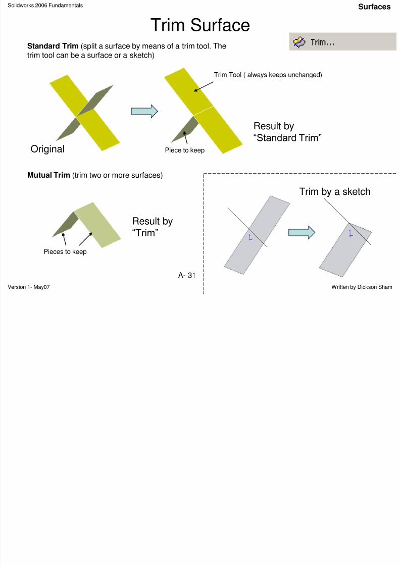
Trim SurfaceStandard Trim (split a surface by means of a trim tool. Thetrim tool can be a surface or a sketch)
Mutual Trim (trim two or more surfaces)
Trim Tool ( always keeps unchanged)
Piece to keep
Result by
“Standard Trim”Original
Result by“Trim”
Pieces to keep
Trim by a sketch
Solidworks 2006 Fundamentals
U i S f
Surfaces
8/2/2019 Solid Works 2006 Fundamentals
http://slidepdf.com/reader/full/solid-works-2006-fundamentals 32/50
Version 1- May07 Written by Dickson ShamA- 32
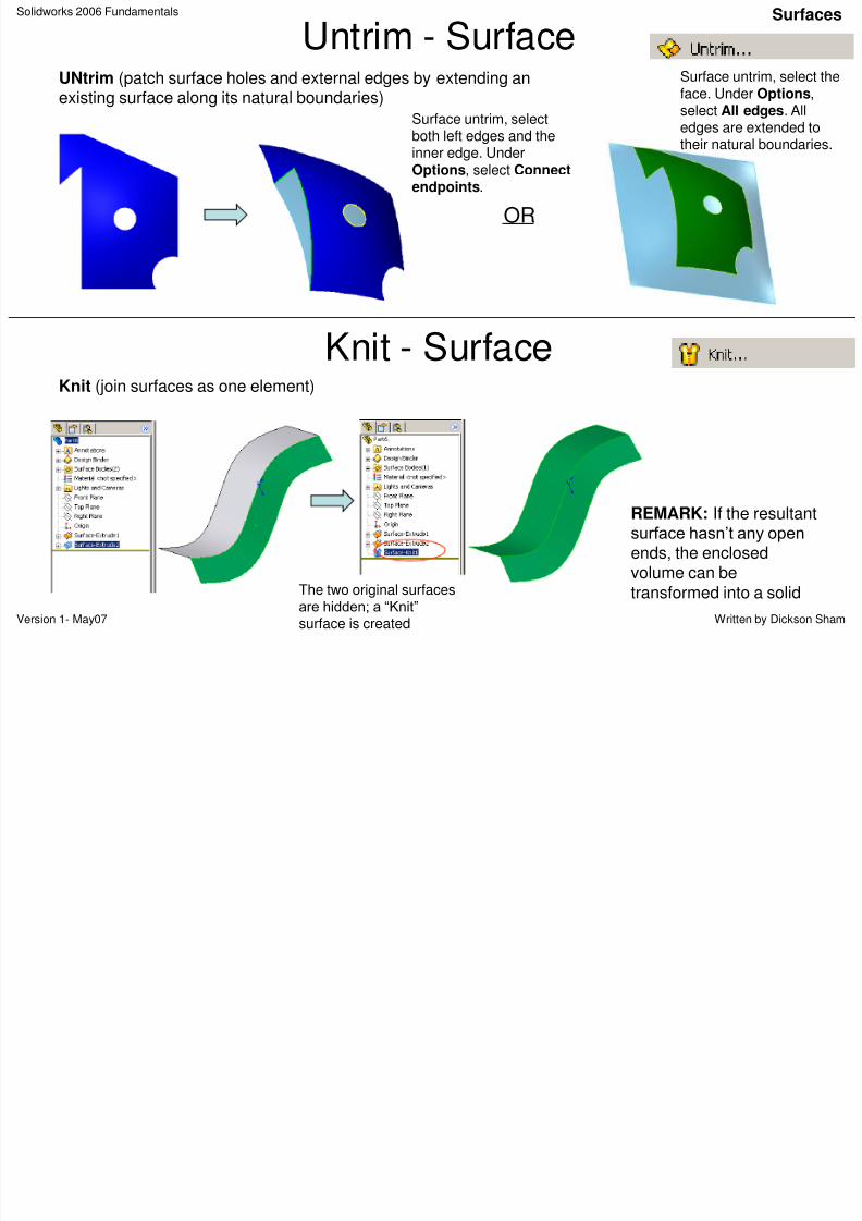
Untrim - Surface
Knit (join surfaces as one element)
The two original surfacesare hidden; a “Knit”
surface is created
REMARK: If the resultantsurface hasn‟t any open
ends, the enclosedvolume can be
transformed into a solid
Knit - Surface
Surface untrim, selectboth left edges and the
inner edge. UnderOptions, select Connectendpoints.
OR
Surface untrim, select theface. Under Options,select All edges. Alledges are extended totheir natural boundaries.
UNtrim (patch surface holes and external edges by extending anexisting surface along its natural boundaries)
Solidworks 2006 Fundamentals Surfaces
8/2/2019 Solid Works 2006 Fundamentals
http://slidepdf.com/reader/full/solid-works-2006-fundamentals 33/50
Version 1- May07 Written by Dickson ShamA- 33
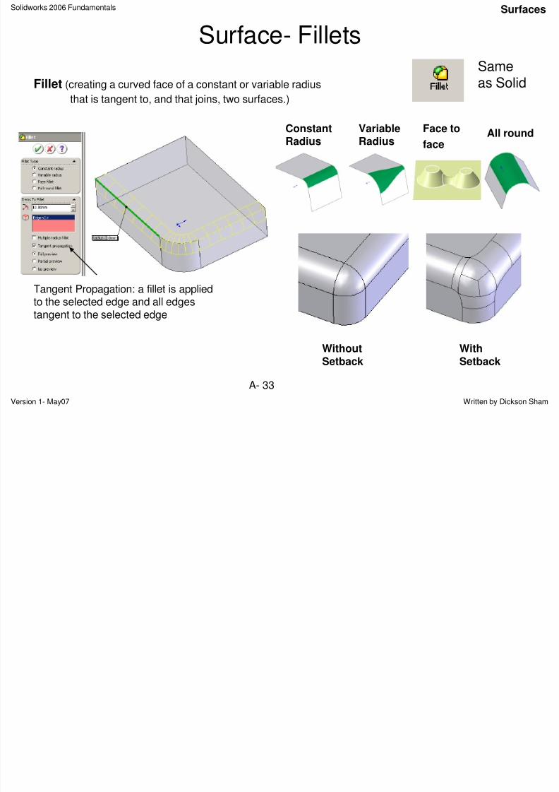
Surface- Fillets
Fillet (creating a curved face of a constant or variable radius
that is tangent to, and that joins, two surfaces.)
ConstantRadius
VariableRadius
Face to
faceAll round
Tangent Propagation: a fillet is appliedto the selected edge and all edgestangent to the selected edge
WithoutSetback
WithSetback
Sameas Solid
Solidworks 2006 Fundamentals
Surfaces
8/2/2019 Solid Works 2006 Fundamentals
http://slidepdf.com/reader/full/solid-works-2006-fundamentals 34/50
Version 1- May07 Written by Dickson ShamA- 34
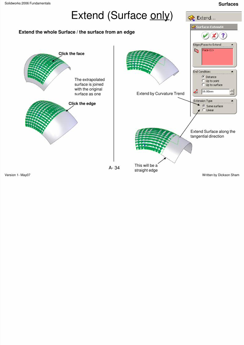
Extend (Surface only)
Extend the whole Surface / the surface from an edge
Extend by Curvature Trend
The extrapolated
surface is joinedwith the originalsurface as one
Extend Surface along thetangential direction
Click the face
Click the edge
This will be a
straight edge
Solidworks 2006 Fundamentals
D f A l iSurfaces
8/2/2019 Solid Works 2006 Fundamentals
http://slidepdf.com/reader/full/solid-works-2006-fundamentals 35/50
Version 1- May07 Written by Dickson ShamA- 35
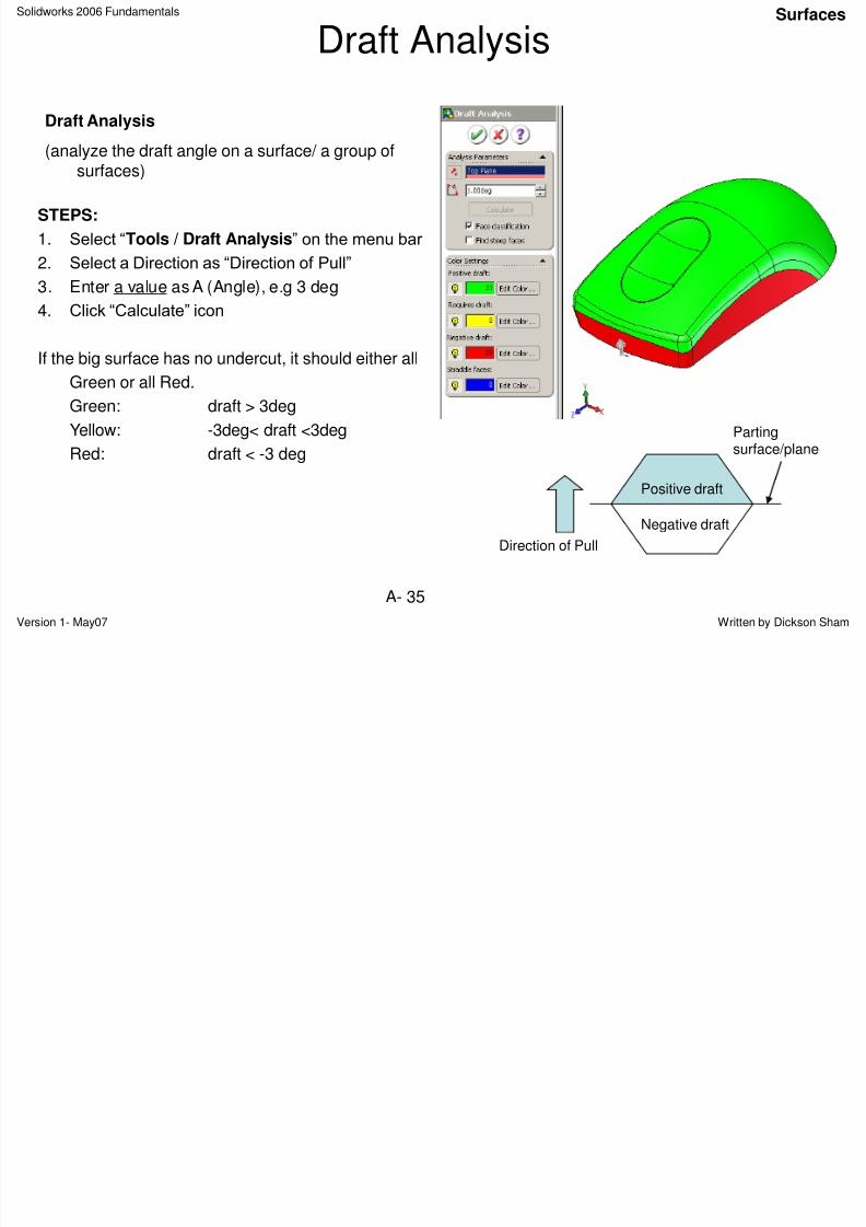
Draft Analysis
Draft Analysis
(analyze the draft angle on a surface/ a group ofsurfaces)
STEPS:
1. Select “Tools / Draft Analysis” on the menu bar
2. Select a Direction as “Direction of Pull”
3. Enter a value as A (Angle), e.g 3 deg
4. Click “Calculate” icon
If the big surface has no undercut, it should either all
Green or all Red.
Green: draft > 3deg
Yellow: -3deg< draft <3deg
Red: draft < -3 deg
Positive draft
Negative draft
Direction of Pull
Parting
surface/plane
Solidworks 2006 Fundamentals Solids + Surfaces
8/2/2019 Solid Works 2006 Fundamentals
http://slidepdf.com/reader/full/solid-works-2006-fundamentals 36/50
Version 1- May07 Written by Dickson ShamA- 36
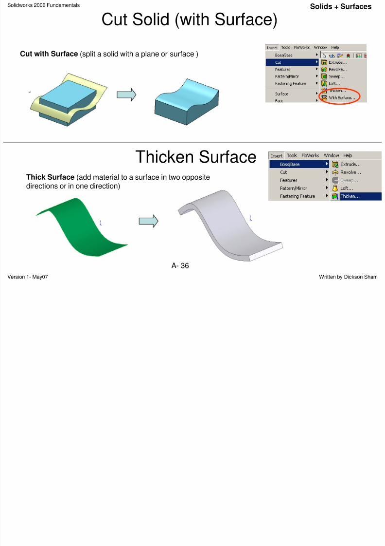
Cut Solid (with Surface)
Cut with Surface (split a solid with a plane or surface )
Thick Surface (add material to a surface in two oppositedirections or in one direction)
Thicken Surface
Solidworks 2006 FundamentalsTransformation
8/2/2019 Solid Works 2006 Fundamentals
http://slidepdf.com/reader/full/solid-works-2006-fundamentals 37/50
Version 1- May07 Written by Dickson ShamA- 37
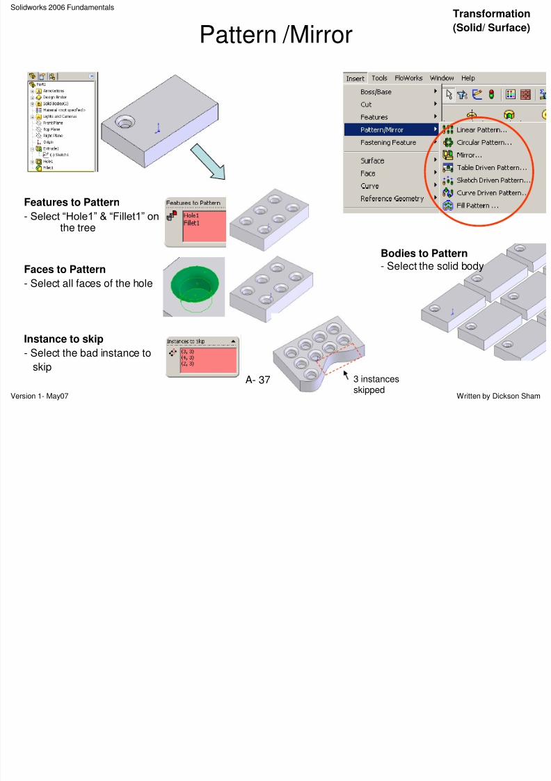
Pattern /Mirror
Features to Pattern
- Select “Hole1” & “Fillet1” onthe tree
Faces to Pattern
- Select all faces of the hole
Instance to skip
- Select the bad instance to
skip
Bodies to Pattern- Select the solid body
3 instancesskipped
a s o at o
(Solid/ Surface)
Solidworks 2006 FundamentalsTransformation
8/2/2019 Solid Works 2006 Fundamentals
http://slidepdf.com/reader/full/solid-works-2006-fundamentals 38/50
Version 1- May07 Written by Dickson ShamA- 38
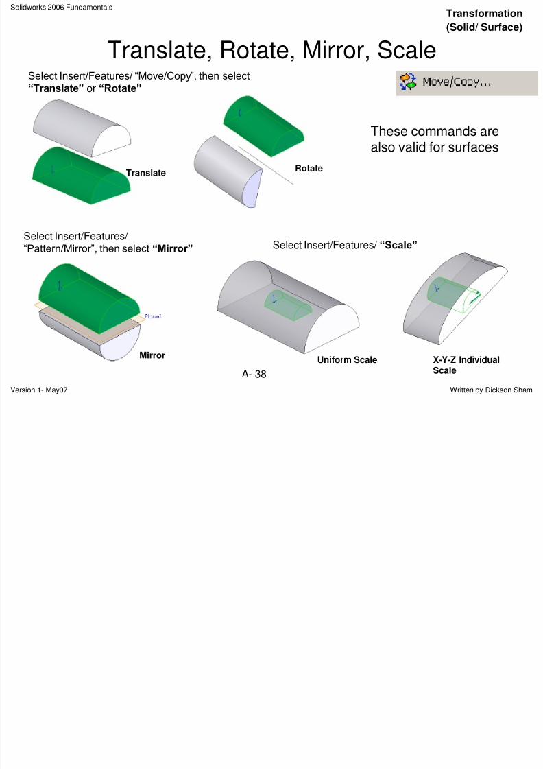
Translate, Rotate, Mirror, Scale
TranslateRotate
MirrorUniform Scale
Select Insert/Features/ “Move/Copy”, then select
“Translate” or “Rotate”
Select Insert/Features/ “Pattern/Mirror”, then select “Mirror”
X-Y-Z IndividualScale
Select Insert/Features/ “Scale”
These commands arealso valid for surfaces
(Solid/ Surface)
Solidworks 2006 Fundamentals
Face ReplaceSolids + Surfaces
8/2/2019 Solid Works 2006 Fundamentals
http://slidepdf.com/reader/full/solid-works-2006-fundamentals 39/50
Version 1- May07 Written by Dickson ShamA- 39
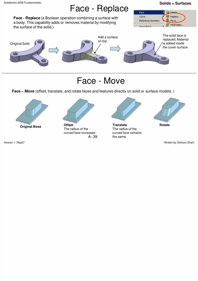
Face - ReplaceFace - Replace (a Boolean operation combining a surface witha body. This capability adds or removes material by modifyingthe surface of the solid.)
Face - Move
Add a surfaceon top
Original Solid
The solid face isreplaced; Materialis added insidethe cover surface
Original BossRotateTranslate
The radius of thecurved face remainsthe same.
OffsetThe radius of thecurved face increases
Face – Move (offset, translate, and rotate faces and features directly on solid or surface models. )
Solidworks 2006 Fundamentals
A bl D iAssembly
8/2/2019 Solid Works 2006 Fundamentals
http://slidepdf.com/reader/full/solid-works-2006-fundamentals 40/50
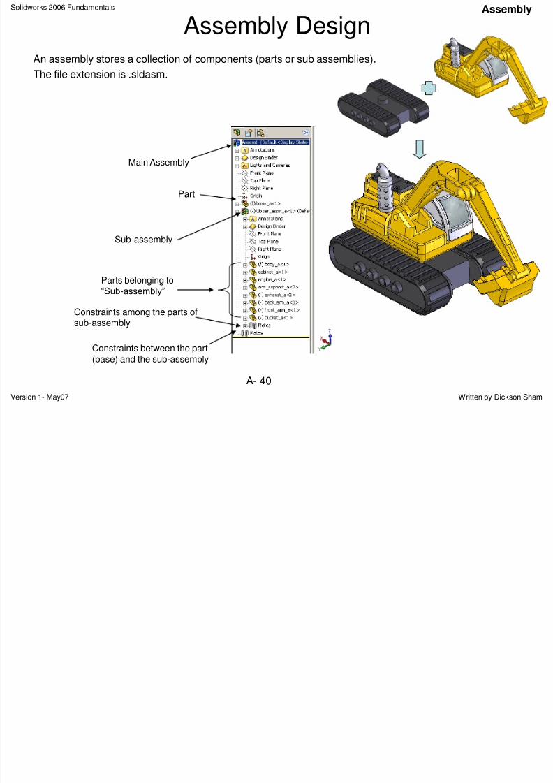
Version 1- May07 Written by Dickson ShamA- 40
Assembly DesignAn assembly stores a collection of components (parts or sub assemblies).
The file extension is .sldasm.
Main Assembly
Part
Sub-assembly
Constraints between the part(base) and the sub-assembly
Parts belonging to
“Sub-assembly”
Constraints among the parts ofsub-assembly
Solidworks 2006 Fundamentals
C t N A blAssembly
8/2/2019 Solid Works 2006 Fundamentals
http://slidepdf.com/reader/full/solid-works-2006-fundamentals 41/50
Version 1- May07 Written by Dickson ShamA- 41
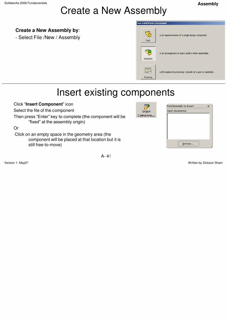
Create a New Assembly
Create a New Assembly by:
- Select File /New / Assembly
Insert existing componentsClick “Insert Component” icon
Select the file of the component
Then press “Enter” key to complete (the component will be
“fixed” at the assembly origin)
Or
Click on an empty space in the geometry area (thecomponent will be placed at that location but it isstill free-to-move)
Solidworks 2006 Fundamentals
Move componentsAssembly
8/2/2019 Solid Works 2006 Fundamentals
http://slidepdf.com/reader/full/solid-works-2006-fundamentals 42/50
Version 1- May07 Written by Dickson ShamA- 42
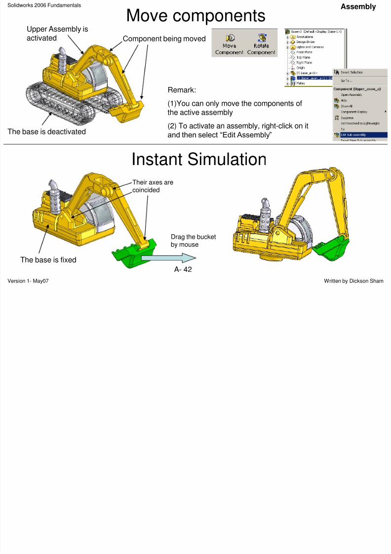
Move componentsUpper Assembly isactivated Component being moved
Instant SimulationTheir axes arecoincided
The base is fixed
Drag the bucketby mouse
The base is deactivated
Remark:
(1)You can only move the components ofthe active assembly
(2) To activate an assembly, right-click on it
and then select “Edit Assembly”
Solidworks 2006 Fundamentals
C t i t b t tAssembly
8/2/2019 Solid Works 2006 Fundamentals
http://slidepdf.com/reader/full/solid-works-2006-fundamentals 43/50
Version 1- May07 Written by Dickson ShamA- 43
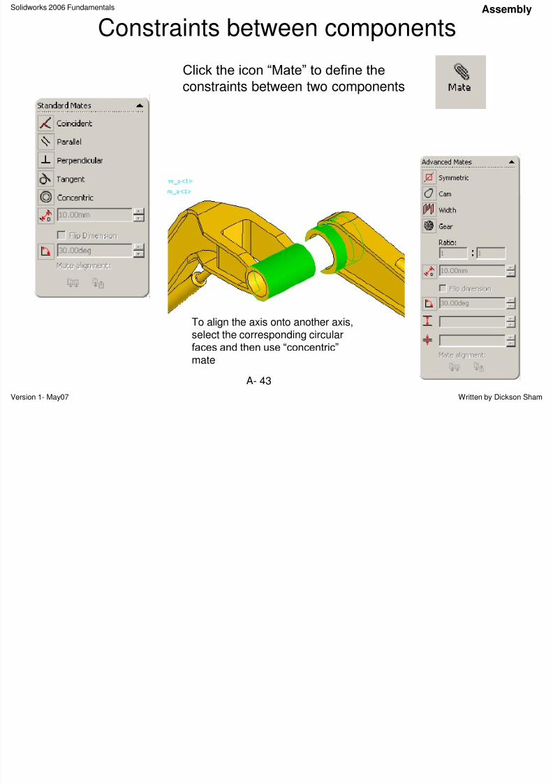
Constraints between components
To align the axis onto another axis,select the corresponding circularfaces and then use “concentric”
mate
Click the icon “Mate” to define the
constraints between two components
Solidworks 2006 Fundamentals
Interference checkAssembly
8/2/2019 Solid Works 2006 Fundamentals
http://slidepdf.com/reader/full/solid-works-2006-fundamentals 44/50
Version 1- May07 Written by Dickson Sham
A- 44
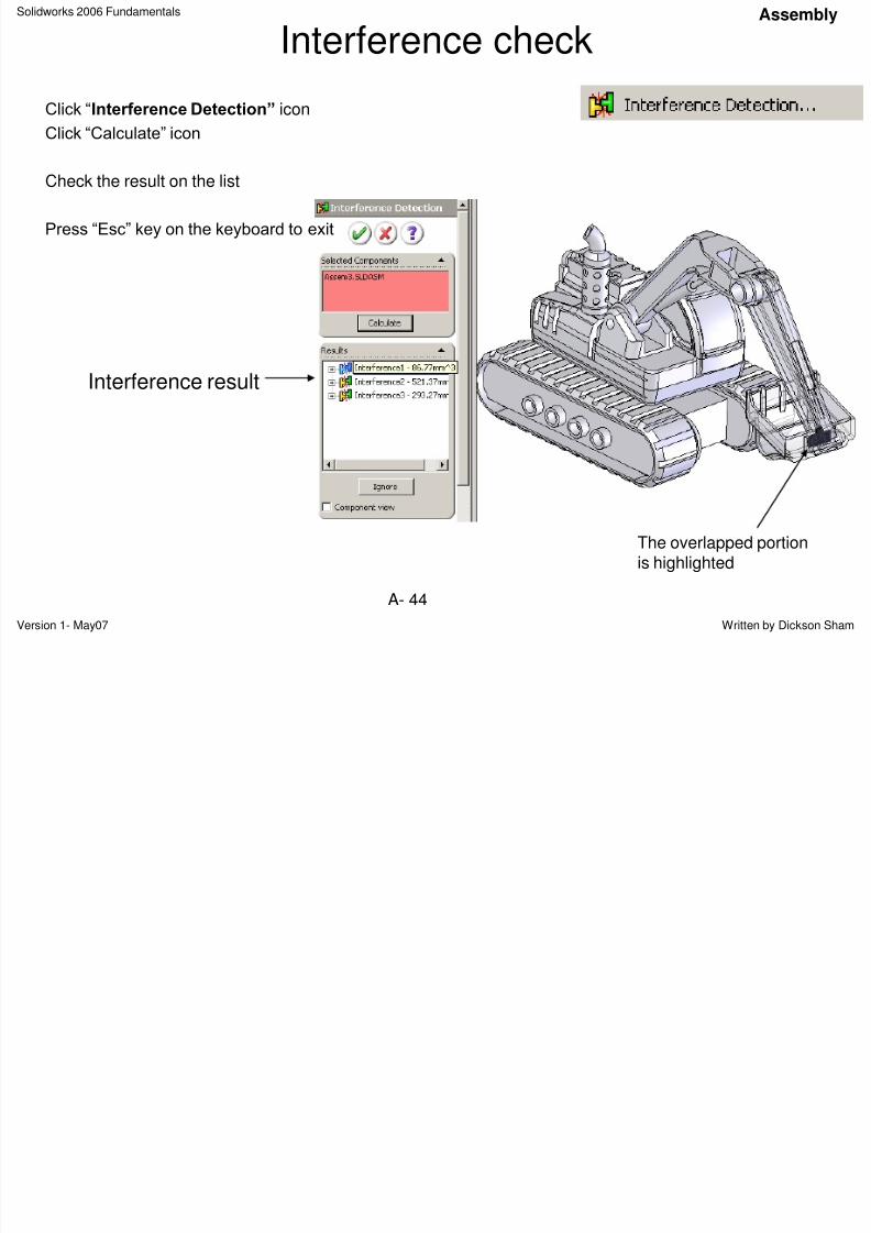
Interference check
Click “Interference Detection” icon
Click “Calculate” icon
Check the result on the list
Press “Esc” key on the keyboard to exit
Interference result
The overlapped portionis highlighted
Solidworks 2006 Fundamentals
Part /Assembly Drawings2D Drawing
8/2/2019 Solid Works 2006 Fundamentals
http://slidepdf.com/reader/full/solid-works-2006-fundamentals 45/50
Version 1- May07 Written by Dickson Sham
A- 45
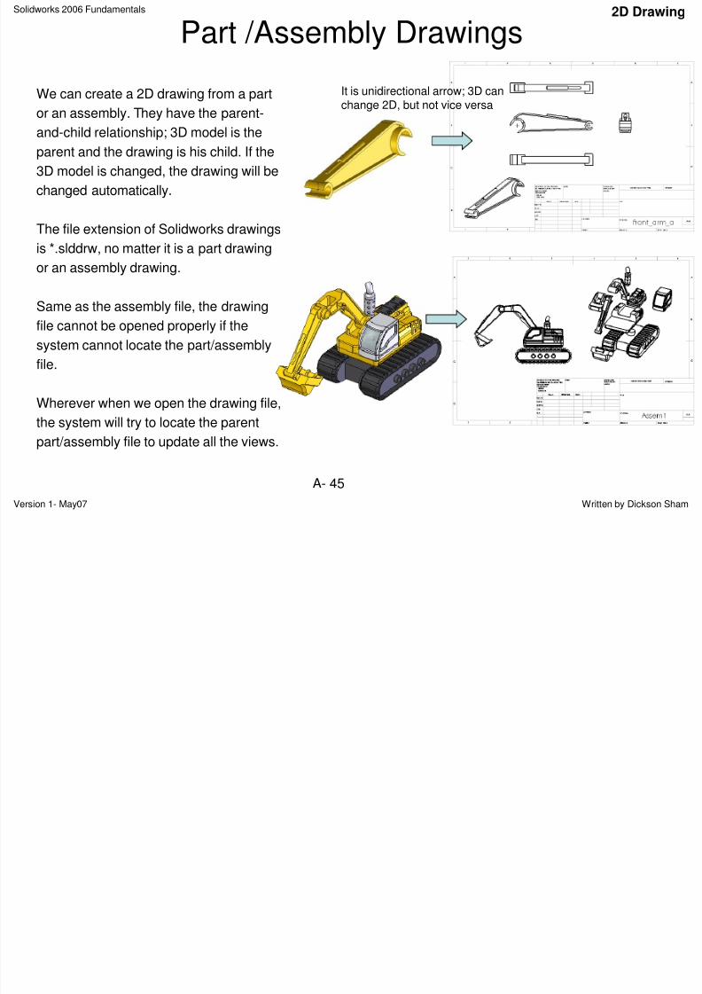
Part /Assembly Drawings
We can create a 2D drawing from a part
or an assembly. They have the parent-
and-child relationship; 3D model is the
parent and the drawing is his child. If the
3D model is changed, the drawing will be
changed automatically.
The file extension of Solidworks drawings
is *.slddrw, no matter it is a part drawingor an assembly drawing.
Same as the assembly file, the drawing
file cannot be opened properly if the
system cannot locate the part/assembly
file.
Wherever when we open the drawing file,
the system will try to locate the parent
part/assembly file to update all the views.
It is unidirectional arrow; 3D canchange 2D, but not vice versa
Solidworks 2006 Fundamentals
Create Views2D Drawing
8/2/2019 Solid Works 2006 Fundamentals
http://slidepdf.com/reader/full/solid-works-2006-fundamentals 46/50
Version 1- May07 Written by Dickson Sham
A- 46
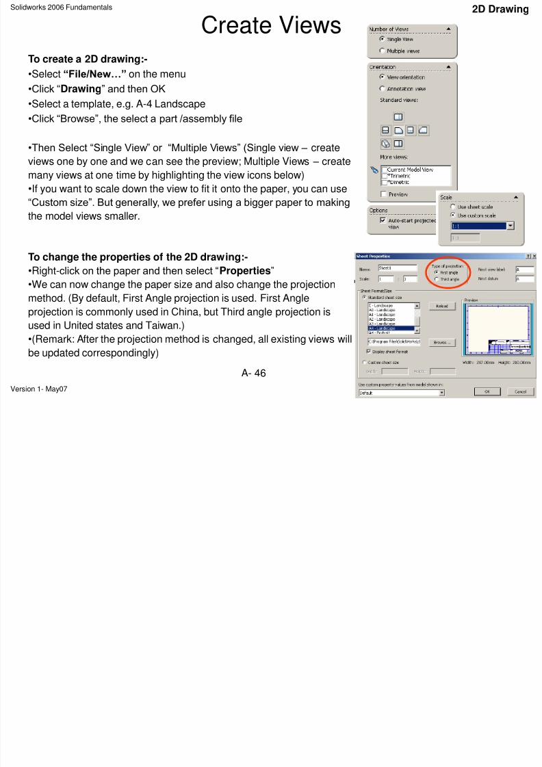
Create Views
To create a 2D drawing:-
•Select “File/New…” on the menu
•Click “Drawing” and then OK
•Select a template, e.g. A-4 Landscape
•Click “Browse”, the select a part /assembly file
•Then Select “Single View” or “Multiple Views” (Single view – create
views one by one and we can see the preview; Multiple Views – create
many views at one time by highlighting the view icons below)
•If you want to scale down the view to fit it onto the paper, you can use“Custom size”. But generally, we prefer using a bigger paper to making
the model views smaller.
To change the properties of the 2D drawing:-
•Right-click on the paper and then select “Properties”
•We can now change the paper size and also change the projectionmethod. (By default, First Angle projection is used. First Angle
projection is commonly used in China, but Third angle projection is
used in United states and Taiwan.)
•(Remark: After the projection method is changed, all existing views will
be updated correspondingly)
Solidworks 2006 Fundamentals
Create Views2D Drawing
8/2/2019 Solid Works 2006 Fundamentals
http://slidepdf.com/reader/full/solid-works-2006-fundamentals 47/50
Version 1- May07 Written by Dickson Sham
A- 47
Create Views
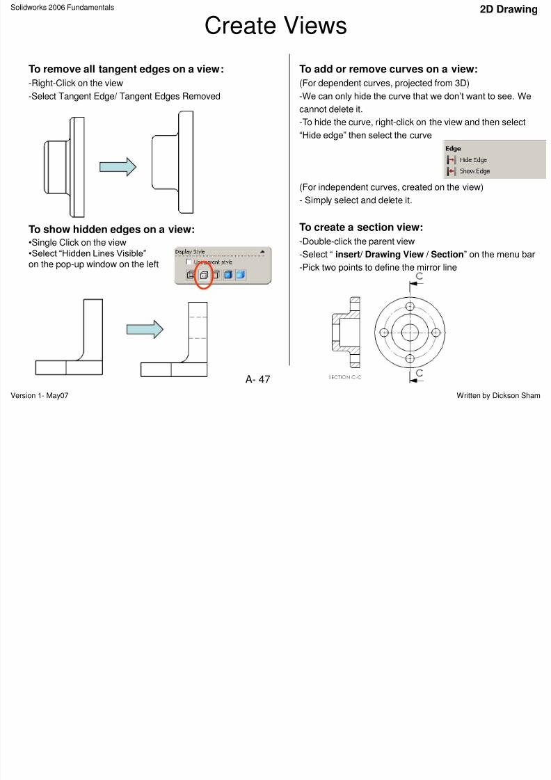
To remove all tangent edges on a view:
-Right-Click on the view
-Select Tangent Edge/ Tangent Edges Removed
To show hidden edges on a view:•Single Click on the view•Select “Hidden Lines Visible”
on the pop-up window on the left
To add or remove curves on a view:
(For dependent curves, projected from 3D)
-We can only hide the curve that we don‟t want to see. Wecannot delete it.
-To hide the curve, right-click on the view and then select
“Hide edge” then select the curve
(For independent curves, created on the view)
- Simply select and delete it.
To create a section view:
-Double-click the parent view
-Select “ insert/ Drawing View / Section” on the menu bar
-Pick two points to define the mirror line
Solidworks 2006 Fundamentals
Dimensioning2D Drawing
8/2/2019 Solid Works 2006 Fundamentals
http://slidepdf.com/reader/full/solid-works-2006-fundamentals 48/50
Version 1- May07 Written by Dickson Sham
A- 48
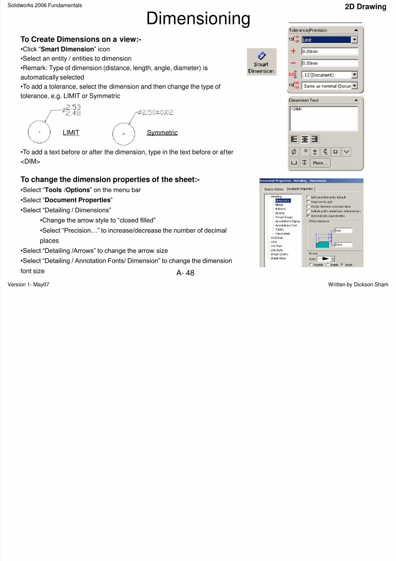
DimensioningTo Create Dimensions on a view:-
•Click “Smart Dimension” icon
•Select an entity / entities to dimension
•Remark: Type of dimension (distance, length, angle, diameter) is
automatically selected
•To add a tolerance, select the dimension and then change the type of
tolerance, e.g. LIMIT or Symmetric
•To add a text before or after the dimension, type in the text before or after
<DIM>
To change the dimension properties of the sheet:-
•Select “Tools /Options” on the menu bar
•Select “Document Properties”
•Select “Detailing / Dimensions”
•Change the arrow style to “closed filled”
•Select “Precision…” to increase/decrease the number of decimal
places
•Select “Detailing /Arrows” to change the arrow size
•Select “Detailing / Annotation Fonts/ Dimension” to change the dimension
font size
LIMIT Symmetric
Solidworks 2006 Fundamentals
Editing Title Block2D Drawing
8/2/2019 Solid Works 2006 Fundamentals
http://slidepdf.com/reader/full/solid-works-2006-fundamentals 49/50
Version 1- May07 Written by Dickson Sham
A- 49
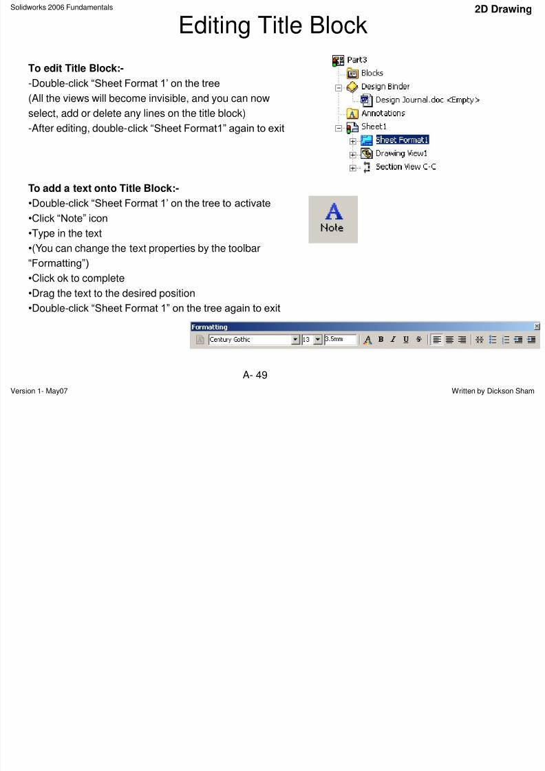
Editing Title Block
To edit Title Block:-
-Double-click “Sheet Format 1‟ on the tree
(All the views will become invisible, and you can nowselect, add or delete any lines on the title block)
-After editing, double-click “Sheet Format1” again to exit
To add a text onto Title Block:-•Double-click “Sheet Format 1‟ on the tree to activate
•Click “Note” icon
•Type in the text
•(You can change the text properties by the toolbar
“Formatting”)
•Click ok to complete
•Drag the text to the desired position
•Double-click “Sheet Format 1” on the tree again to exit
Solidworks 2006 Fundamentals
Equations and Design TablesParameters
8/2/2019 Solid Works 2006 Fundamentals
http://slidepdf.com/reader/full/solid-works-2006-fundamentals 50/50
A- 50
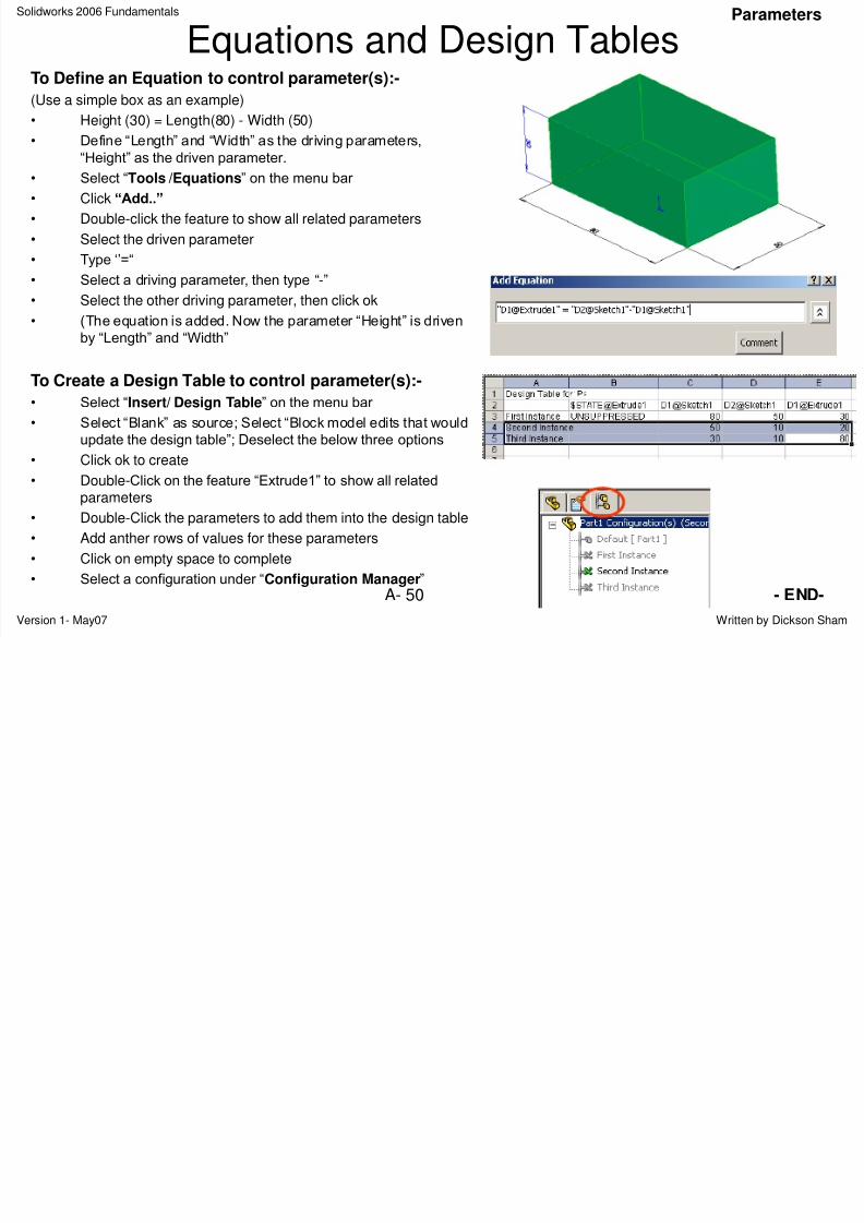
Equations and Design TablesTo Define an Equation to control parameter(s):-
(Use a simple box as an example)
• Height (30) = Length(80) - Width (50)
• Define “Length” and “Width” as the driving parameters,
“Height” as the driven parameter.• Select “Tools /Equations” on the menu bar
• Click “Add..”
• Double-click the feature to show all related parameters
• Select the driven parameter
• Type „‟=“
• Select a driving parameter, then type “-”
• Select the other driving parameter, then click ok• (The equation is added. Now the parameter “Height” is driven
by “Length” and “Width”
To Create a Design Table to control parameter(s):-
• Select “Insert/ Design Table” on the menu bar
• Select “Blank” as source; Select “Block model edits that would
update the design table”; Deselect the below three options
• Click ok to create
• Double-Click on the feature “Extrude1” to show all related
parameters
• Double-Click the parameters to add them into the design table
• Add anther rows of values for these parameters
• Click on empty space to complete
• Select a configuration under “Configuration Manager”- END-