Embed Size (px)
Citation preview
Solid Works surfaces tutorial
1
Tutorial Surfaces SolidWorks 2015 – Example
2 – Make the model of a airplane. The purpose of this tutorial is to practice the commnads with surfaces, obtaining the outer shell of an airplane. The work is not so complex, but takes time to complete. Sometimes an iterative process is necessary to obtain the intended result (do not quit easily!)
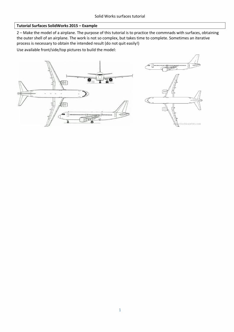
Use available front/side/top pictures to build the model:
Solid Works surfaces tutorial
2
Solid Works surfaces tutorial
3
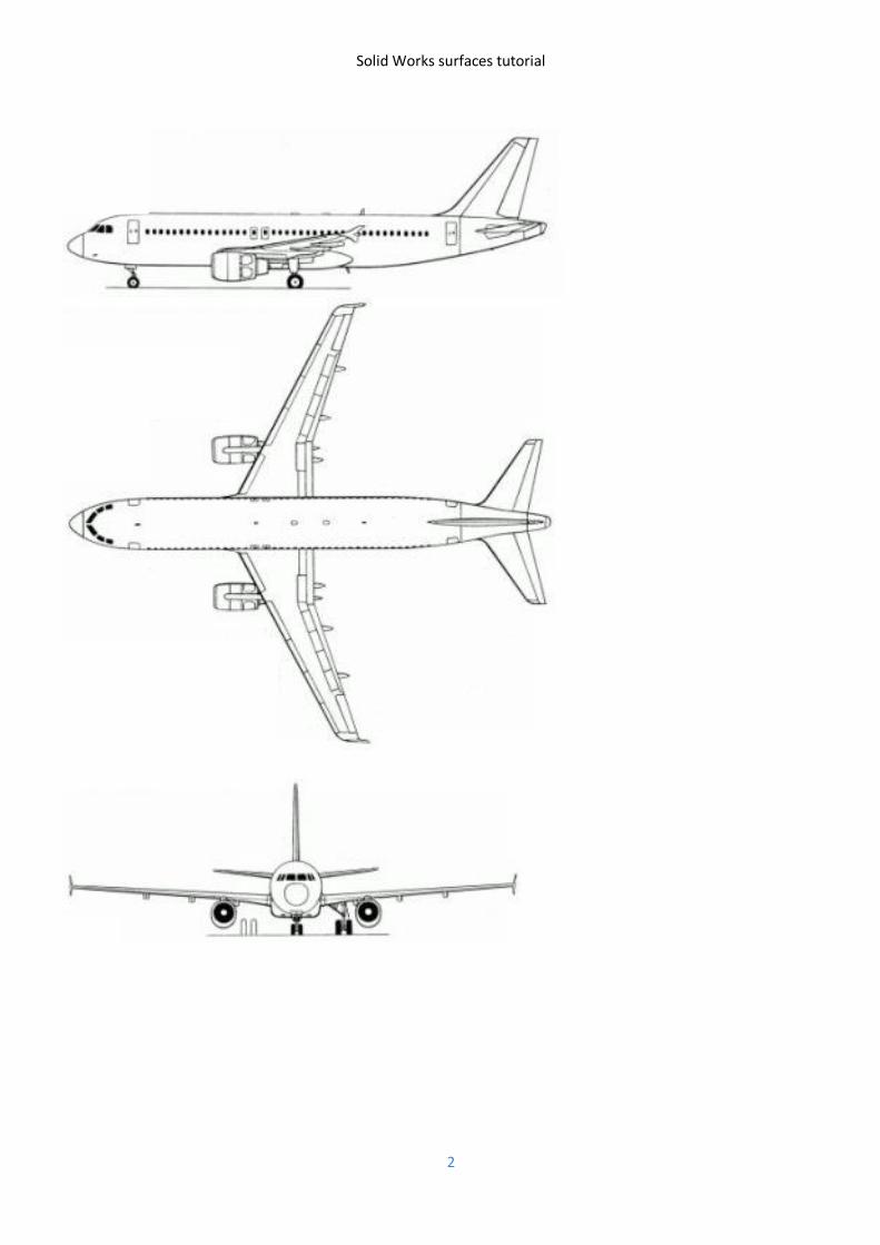
Create a sketck on top plane. Insert the top picture (menu Tools->Sketch Tools->Sketch Picture). Create a centerline along the origin. Move the picture to align it with the centerline. Create another centerline, perpendicular to the first one, close to the frontmost point of the left engine, see picture.
Repeat the procedures with the frontal and side views.
Create 2 new planes. One is parallel to the front plane passing throught the center of the nose wheel (here named BackCabinePlane). The other is parallel to the top plane passing throught the frontmost point of the nose (named TopPlaneOnNose).
On the Right plane create the spline on top of the background image for the nose.
Solid Works surfaces tutorial
4
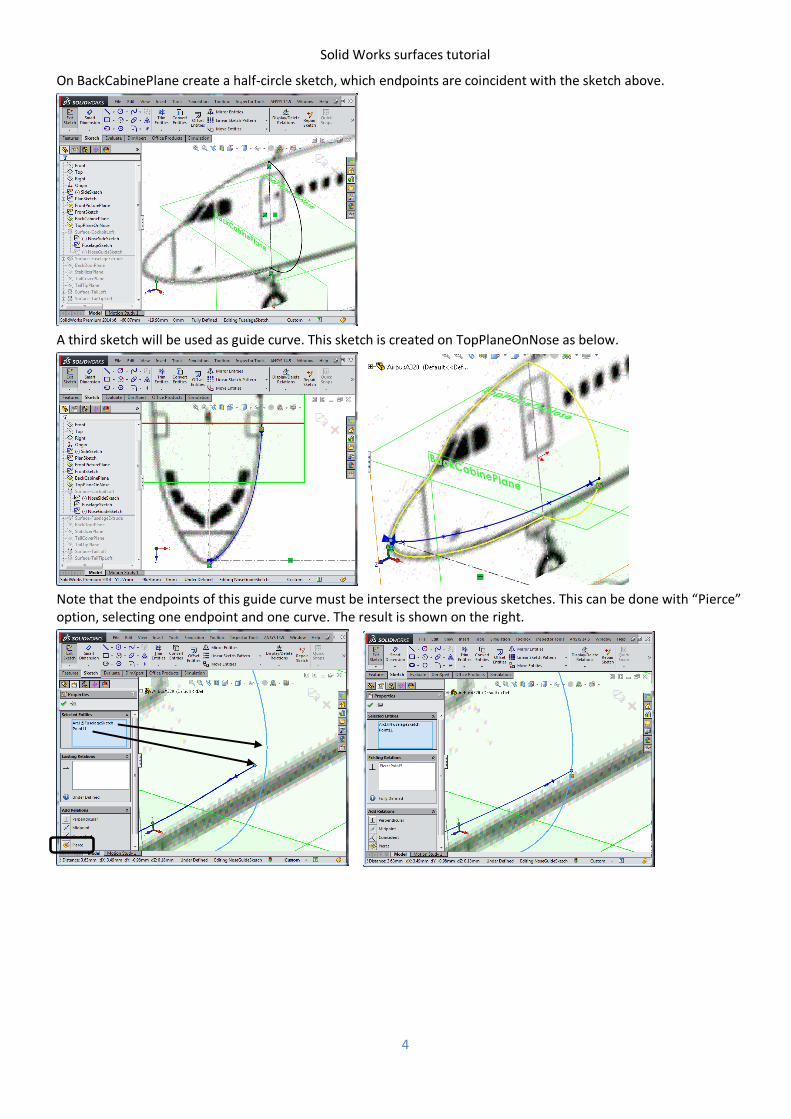
On BackCabinePlane create a half-circle sketch, which endpoints are coincident with the sketch above.
A third sketch will be used as guide curve. This sketch is created on TopPlaneOnNose as below.
Note that the endpoints of this guide curve must be intersect the previous sketches. This can be done with “Pierce” option, selecting one endpoint and one curve. The result is shown on the right.
Solid Works surfaces tutorial
5
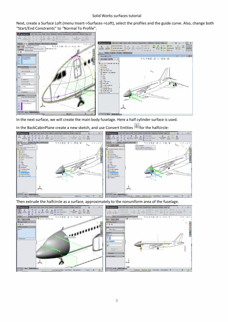
Next, create a Surface Loft (menu Insert->Surfaces->Loft), select the profiles and the guide curve. Also, change both “Start/End Constraints” to “Normal To Profile”.
In the next surface, we will create the main body fuselage. Here a half cylinder surface is used.
In the BackCabinPlane create a new sketch, and use Convert Entities for the halfcircle:
Then extrude the halfcircle as a surface, approximately to the nonuniform area of the fuselage.
Solid Works surfaces tutorial
6
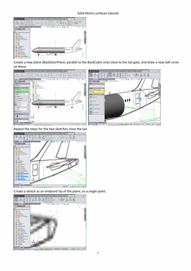
Create a new plane (BackDoorPlane, parallel to the BackCabin one) close to the tail gate, and draw a new half circle on there.
Repeat the steps for the two sketches close the tail.
Create a sketch as an endpoint tip of the plane, as a single point:
Solid Works surfaces tutorial
7
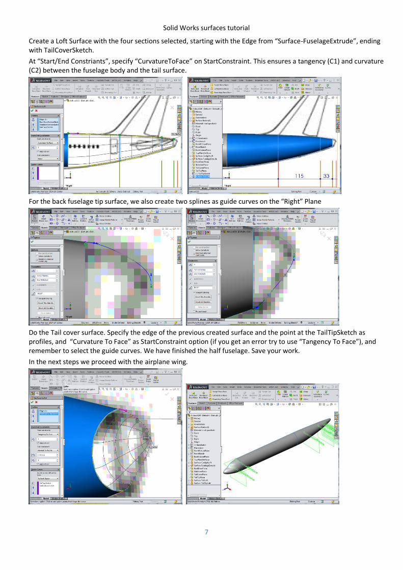
Create a Loft Surface with the four sections selected, starting with the Edge from “Surface-FuselageExtrude”, ending with TailCoverSketch.
At “Start/End Constriants”, specify “CurvatureToFace” on StartConstraint. This ensures a tangency (C1) and curvature (C2) between the fuselage body and the tail surface.
For the back fuselage tip surface, we also create two splines as guide curves on the “Right” Plane
Do the Tail cover surface. Specify the edge of the previous created surface and the point at the TailTipSketch as profiles, and “Curvature To Face” as StartConstraint option (if you get an error try to use “Tangency To Face”), and remember to select the guide curves. We have finished the half fuselage. Save your work.
In the next steps we proceed with the airplane wing.
Solid Works surfaces tutorial
8
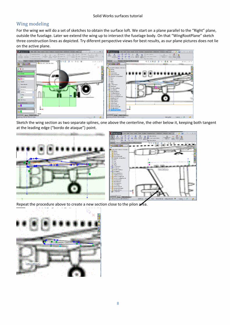
Wing modeling
For the wing we will do a set of sketches to obtain the surface loft. We start on a plane parallel to the “Right” plane, outside the fuselage. Later we extend the wing up to intersect the fuselage body. On that “WingRootPlane” sketch three construction lines as depicted. Try diferent perspective views for best results, as our plane pictures does not lie on the active plane.
Sketch the wing section as two separate splines, one above the centerline, the other below it, keeping both tangent at the leading edge (“bordo de ataque”) point.
Repeat the procedure above to create a new section close to the pilon area.
Solid Works surfaces tutorial
9
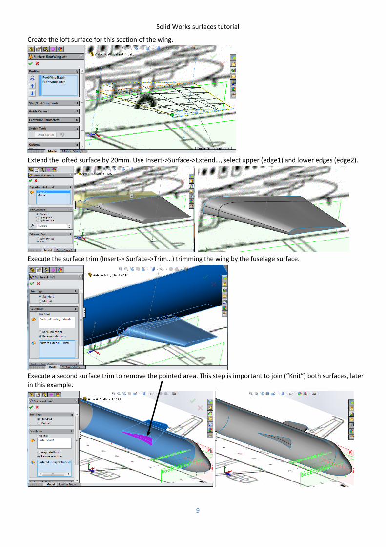
Create the loft surface for this section of the wing.
Extend the lofted surface by 20mm. Use Insert->Surface->Extend…, select upper (edge1) and lower edges (edge2).
Execute the surface trim (Insert-> Surface->Trim…) trimming the wing by the fuselage surface.
Execute a second surface trim to remove the pointed area. This step is important to join (“Knit”) both surfaces, later in this example.
Solid Works surfaces tutorial
10
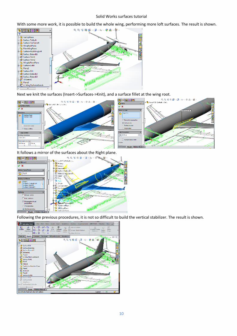
With some more work, it is possible to build the whole wing, performing more loft surfaces. The result is shown.
Next we knit the surfaces (Insert->Surfaces->Knit), and a surface fillet at the wing root.
It follows a mirror of the surfaces about the Right plane.
Following the previous procedures, it is not so difficult to build the vertical stabilizer. The result is shown.
Solid Works surfaces tutorial
11
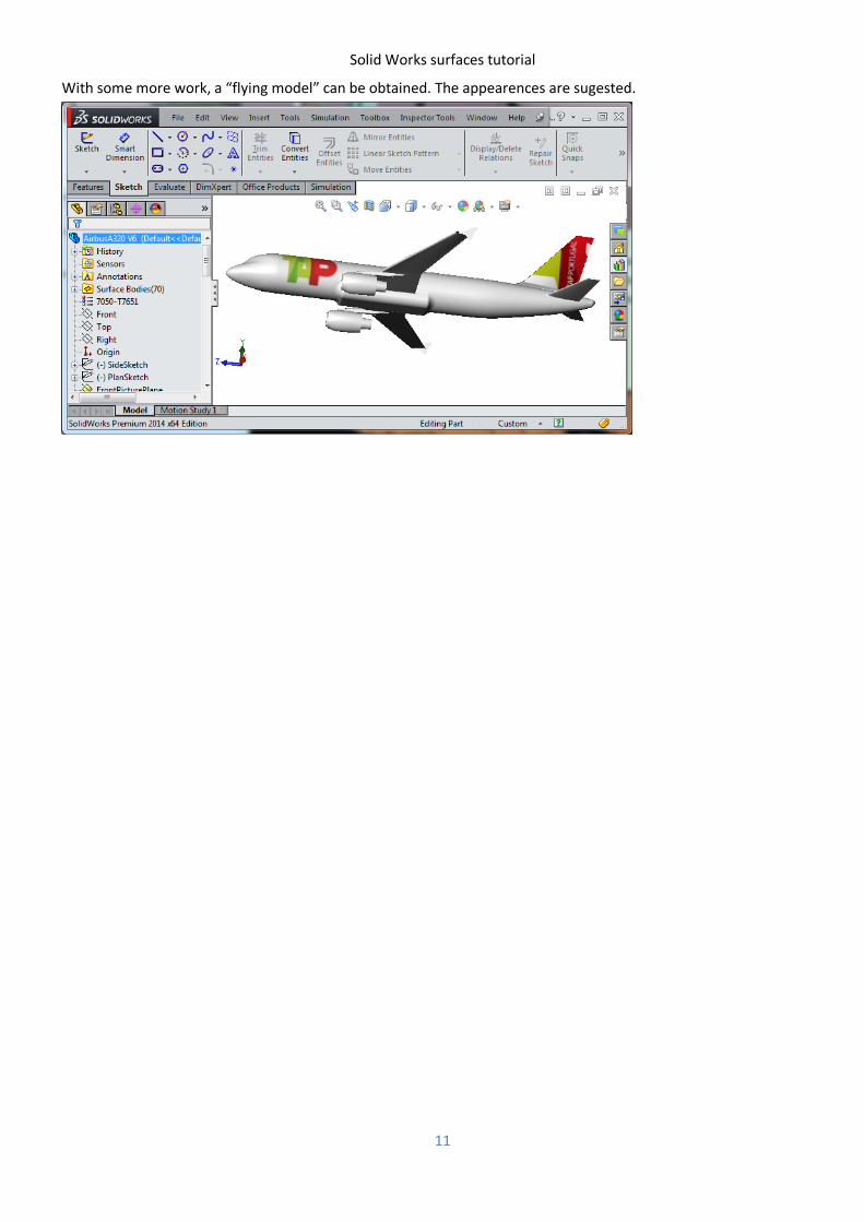
With some more work, a “flying model” can be obtained. The appearences are sugested.