Embed Size (px)
Citation preview
SolidificationandStabilizationof WastesUsingPortlandCementby Wayne S. Adaska, Stewart W. Tresouthick, andPresbury B. West
EB071
PORTLANDCEMENT ASSOCIATION
Solidification andStabilization of WastesUsing Portland CementThis engineering bulletin was written by Wayne S. Adaska,Portland Cement Association; Stewart W. Tresouthick(retired) and Presbury B. West, Construction TechnologyLaboratories, Inc., 2nd edition edited by Charles M. Wilk,Portland Cement Association.
Portland Cement Association5420 Old Orchard Rd.Skokie, IL 60077-1083USATel; (847) 966-6200Fax: (847) 966-9781www.portcement.org
© 1991 Portland Cement AssociationAll rights reserved. No part of this publication may bereproduced, stored in a retrieval system, or transmitted inany form or by any means, electronic, mechanical, photo-copying, recording, or otherwise, without the prior per-mission of the copyright owner.
First printing 1991Second printing (rev.) 1994Second edition 1998
ISBN 0-893120960
Printed in the United States of America
This publication is intended SOLELY for use by PROFES-SIONAL PERSONNEL who are competent to evaluate thesignificance and limitations of the information provided herein,and who will accept total responsibility for the application ofthis information. The Portland Cement Association DISCLAIMSany and all RESPONSIBILITY and LIABILITY for the accu-racy of and the application of the information contained in thispublication to the full extent permitted by law.
Cover page photo credit: Courtesy of Laura Powers,Construction Technology Laboratories. Contaminated soilfrom former wood treatment facility treated by portlandcement-based S/S. Magnification 200X, in cross-polar-ized light with gypsum accessory plate. #A7068.
WARNING: Contact with wet (unhardened) concrete, mortar, cement, or cementmixtures can cause SKIN IRRITATION, SEVERE CHEMICAL BURNS (THIRD-DEGREE),or SERIOUS EYE DAMAGE. Frequent exposure may be associated with irritant and/orallergic contact dermatitis. Wear waterproof gloves, a long-sleeved shirt, full-lengthtrousers, and proper eye protection when working with these materials. If you have tostand in wet concrete, use waterproof boots that are high enough to keep concrete fromflowing into them. Wash wet concrete, mortar, cement, or cement mixtures from your skinimmediately. Flush eyes with clean water immediately after contact. Indirect contactthrough clothing can be as serious as direct contact, so promptly rinse out wet concrete,mortar, cement, or cement mixtures from clothing. Seek immediate medical attention ifyou have persistent or severe discomfort.
EB071.02
CONTENTSIntroduction .......................................................1
Terminology ......................................................2
Regulatory Basis for Use of S/S Processes .......3
Portland Cement ................................................4Manufacturing Portland Cement ..................4Cement Kiln Dust ........................................6Portland Cement Chemistry .........................6
Compounds Formed in the Kiln .............6Cement Hydration ...................................7
Use of Additives in S/S Systems .......................9
Stabilization of Metals ....................................10Role of Calcium Silicate Hydrate inStabilization of Metals ............................... 11Individual Metals in Cement-BasedS/S Systems................................................ 11
Wastes Containing Organic Compounds ........12
Waste Components Causing Interference .......13
Treatment Characterization ......................... . . 14
References .......................................................16
PrefaceSolidification and stabilization (S/S) technology is cur-rently being used to treat a wide variety of wastes. Al-though considerable information is available on S/S tech-nology, much of it addresses research work or case stud-ies on specific waste sites. This material usually containsvery little on the characteristics of the binding agent usedto treat the wastes. In addition, chemical reactions thatoccur during waste treatment are generally presented forthose who are highly technically oriented. As a result,there is still a lack of familiarity with S/S technologyamong many consulting engineers, material suppliers,government officials, waste site owners, and the generalpublic. This publication is intended to explain whatportland cement is and how it can be used to solidify andstabilize various wastes.
The Portland Cement Association contracted Construc-tion Technology Laboratories, Inc., (CTL) to prepare astate-of-the-art report on waste stabilization using port-land cement. This engineering bulletin was developedfrom that report.
The authors wish to acknowledge contributions madeby the many individuals who provided valuable assis-tance in preparing this bulletin. A special thanks to thefollowing for reviewing the CTL draft report:Edwin F. Barth, USEPA; Walter Grube, Jr.,USEPA: Jesse R. Conner, Chemical Waste Manage-ment; Julia Stegemann, Environment Canada;Alexander J. Fazzini and Robert J. Collins,VFL Technology Corp.; and several cement companyrepresentatives too numerous to list.
by Wayne S. Adaska, Stewart W. Tresouthick, and Presbury B. West
Solidification and Stabilizationof Wastes Using Portland Cement
1
Solidification and Stabilization of WastesUsing Portland Cement
IntroductionPortland cement is well known for its use in concrete. Itis the “glue” that holds the mass together. Concrete’shigh strength, low permeability, and resistance to mostchemicals makes it an ideal material for waste contain-ment. In addition to concrete structures, there are manyother applications for portland cement that are worthy ofnote. Some of these include:
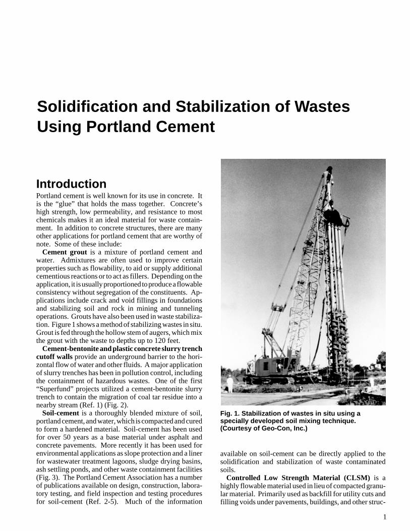
Cement grout is a mixture of portland cement andwater. Admixtures are often used to improve certainproperties such as flowability, to aid or supply additionalcementious reactions or to act as fillers. Depending on theapplication, it is usually proportioned to produce a flowableconsistency without segregation of the constituents. Ap-plications include crack and void fillings in foundationsand stabilizing soil and rock in mining and tunnelingoperations. Grouts have also been used in waste stabiliza-tion. Figure 1 shows a method of stabilizing wastes in situ.Grout is fed through the hollow stem of augers, which mixthe grout with the waste to depths up to 120 feet.
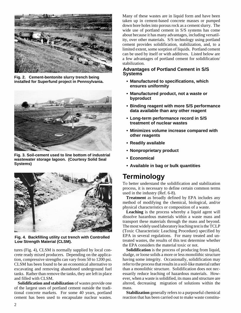
Cement-bentonite and plastic concrete slurry trenchcutoff walls provide an underground barrier to the hori-zontal flow of water and other fluids. A major applicationof slurry trenches has been in pollution control, includingthe containment of hazardous wastes. One of the first“Superfund” projects utilized a cement-bentonite slurrytrench to contain the migration of coal tar residue into anearby stream (Ref. 1) (Fig. 2).
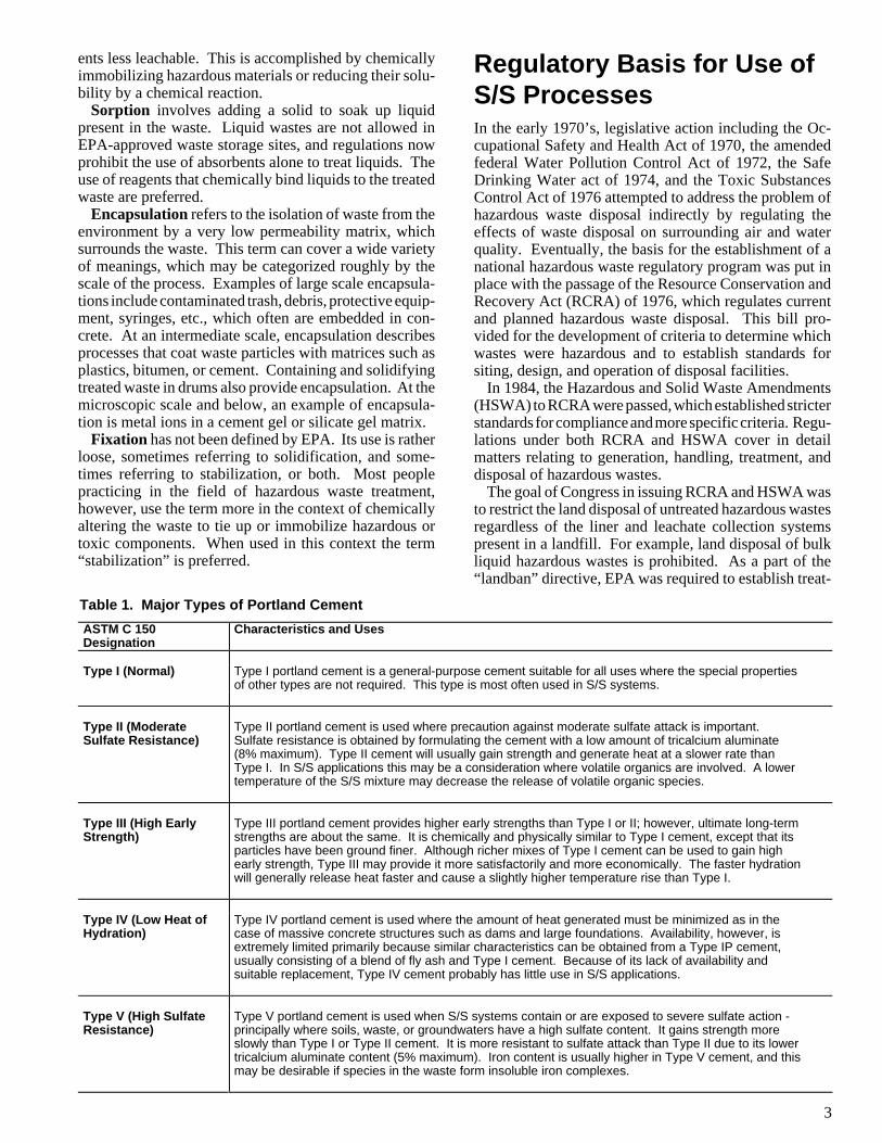
Soil-cement is a thoroughly blended mixture of soil,portland cement, and water, which is compacted and curedto form a hardened material. Soil-cement has been usedfor over 50 years as a base material under asphalt andconcrete pavements. More recently it has been used forenvironmental applications as slope protection and a linerfor wastewater treatment lagoons, sludge drying basins,ash settling ponds, and other waste containment facilities(Fig. 3). The Portland Cement Association has a numberof publications available on design, construction, labora-tory testing, and field inspection and testing proceduresfor soil-cement (Ref. 2-5). Much of the information
Fig. 1. Stabilization of wastes in situ using aspecially developed soil mixing technique.(Courtesy of Geo-Con, Inc.)
available on soil-cement can be directly applied to thesolidification and stabilization of waste contaminatedsoils.
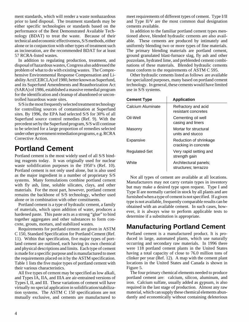
Controlled Low Strength Material (CLSM) is ahighly flowable material used in lieu of compacted granu-lar material. Primarily used as backfill for utility cuts andfilling voids under pavements, buildings, and other struc-
2
Fig. 2. Cement-bentonite slurry trench beinginstalled for Superfund project in Pennsylvania.
Many of these wastes are in liquid form and have beentaken up in cement-based concrete masses or pumpeddown bore holes into porous rock as a cement slurry. Thewide use of portland cement in S/S systems has comeabout because it has many advantages, including versatil-ity, over other materials. S/S technology using portlandcement provides solidification, stabilization, and, to alimited extent, some sorption of liquids. Portland cementcan be used by itself or with additives. Listed below area few advantages of portland cement for solidification/stabilization.
Fig. 3. Soil-cement used to line bottom of industrialwastewater storage lagoon. (Courtesy Solid SealSystems)
Advantages of Portland Cement in S/SSystems
• Manufactured to specifications, whichensures uniformity
• Manufactured product, not a waste orbyproduct
• Binding reagent with more S/S performancedata available than any other reagent
• Long-term performance record in S/Streatment of nuclear wastes
• Minimizes volume increase compared withother reagents
• Readily available
• Nonproprietary product
• Economical
• Available in bag or bulk quantities
Fig. 4. Backfilling utility cut trench with ControlledLow Strength Material (CLSM).
TerminologyTo better understand the solidification and stabilizationprocess, it is necessary to define certain common termsused in the industry (Ref. 6-8).
Treatment as broadly defined by EPA includes anymethod of modifying the chemical, biological, and/orphysical characteristics or composition of a waste.
Leaching is the process whereby a liquid agent willdissolve hazardous materials within a waste mass andtransport these materials through the mass and beyond.The most widely used laboratory leaching test is the TCLP(Toxic Characteristic Leaching Procedure) specified byEPA in several regulations. For many treated and un-treated wastes, the results of this test determine whetherthe EPA considers the material toxic or not.
Solidification is the process of producing from liquid,sludge, or loose solids a more or less monolithic structurehaving some integrity. Occasionally, solidification mayrefer to the process that results in a soil-like material ratherthan a monolithic structure. Solidification does not nec-essarily reduce leaching of hazardous materials. How-ever, when a waste is solidified, its mass and structure arealtered, decreasing migration of solutions within themass.
Stabilization generally refers to a purposeful chemicalreaction that has been carried out to make waste constitu-
tures (Fig. 4), CLSM is normally supplied by local con-crete ready mixed producers. Depending on the applica-tion, compressive strengths can vary from 50 to 1200 psi.CLSM has been found to be an economical alternative toexcavating and removing abandoned underground fueltanks. Rather than remove the tanks, they are left in placeand filled with CLSM.
Solidification and stabilization of wastes provide oneof the largest uses of portland cement outside the tradi-tional concrete markets. For some 40 years, portlandcement has been used to encapsulate nuclear wastes.
3
ents less leachable. This is accomplished by chemicallyimmobilizing hazardous materials or reducing their solu-bility by a chemical reaction.
Sorption involves adding a solid to soak up liquidpresent in the waste. Liquid wastes are not allowed inEPA-approved waste storage sites, and regulations nowprohibit the use of absorbents alone to treat liquids. Theuse of reagents that chemically bind liquids to the treatedwaste are preferred.
Encapsulation refers to the isolation of waste from theenvironment by a very low permeability matrix, whichsurrounds the waste. This term can cover a wide varietyof meanings, which may be categorized roughly by thescale of the process. Examples of large scale encapsula-tions include contaminated trash, debris, protective equip-ment, syringes, etc., which often are embedded in con-crete. At an intermediate scale, encapsulation describesprocesses that coat waste particles with matrices such asplastics, bitumen, or cement. Containing and solidifyingtreated waste in drums also provide encapsulation. At themicroscopic scale and below, an example of encapsula-tion is metal ions in a cement gel or silicate gel matrix.
Fixation has not been defined by EPA. Its use is ratherloose, sometimes referring to solidification, and some-times referring to stabilization, or both. Most peoplepracticing in the field of hazardous waste treatment,however, use the term more in the context of chemicallyaltering the waste to tie up or immobilize hazardous ortoxic components. When used in this context the term“stabilization” is preferred.
ASTM C 150 Designation
Characteristics and Uses
Type I (Normal) Type I portland cement is a general-purpose cement suitable for all uses where the special propertiesof other types are not required. This type is most often used in S/S systems.
Type II (ModerateSulfate Resistance)
Type II portland cement is used where precaution against moderate sulfate attack is important. Sulfate resistance is obtained by formulating the cement with a low amount of tricalcium aluminate(8% maximum). Type II cement will usually gain strength and generate heat at a slower rate thanType I. In S/S applications this may be a consideration where volatile organics are involved. A lowertemperature of the S/S mixture may decrease the release of volatile organic species.
Type III (High EarlyStrength)
Type III portland cement provides higher early strengths than Type I or II; however, ultimate long-termstrengths are about the same. It is chemically and physically similar to Type I cement, except that itsparticles have been ground finer. Although richer mixes of Type I cement can be used to gain highearly strength, Type III may provide it more satisfactorily and more economically. The faster hydrationwill generally release heat faster and cause a slightly higher temperature rise than Type I.
Type IV (Low Heat ofHydration)
Type IV portland cement is used where the amount of heat generated must be minimized as in thecase of massive concrete structures such as dams and large foundations. Availability, however, isextremely limited primarily because similar characteristics can be obtained from a Type IP cement,usually consisting of a blend of fly ash and Type I cement. Because of its lack of availability andsuitable replacement, Type IV cement probably has little use in S/S applications.
Type V (High SulfateResistance)
Type V portland cement is used when S/S systems contain or are exposed to severe sulfate action -principally where soils, waste, or groundwaters have a high sulfate content. It gains strength moreslowly than Type I or Type II cement. It is more resistant to sulfate attack than Type II due to its lowertricalcium aluminate content (5% maximum). Iron content is usually higher in Type V cement, and thismay be desirable if species in the waste form insoluble iron complexes.
Table 1. Major Types of Portland Cement
Regulatory Basis for Use ofS/S ProcessesIn the early 1970’s, legislative action including the Oc-cupational Safety and Health Act of 1970, the amendedfederal Water Pollution Control Act of 1972, the SafeDrinking Water act of 1974, and the Toxic SubstancesControl Act of 1976 attempted to address the problem ofhazardous waste disposal indirectly by regulating theeffects of waste disposal on surrounding air and waterquality. Eventually, the basis for the establishment of anational hazardous waste regulatory program was put inplace with the passage of the Resource Conservation andRecovery Act (RCRA) of 1976, which regulates currentand planned hazardous waste disposal. This bill pro-vided for the development of criteria to determine whichwastes were hazardous and to establish standards forsiting, design, and operation of disposal facilities.
In 1984, the Hazardous and Solid Waste Amendments(HSWA) to RCRA were passed, which established stricterstandards for compliance and more specific criteria. Regu-lations under both RCRA and HSWA cover in detailmatters relating to generation, handling, treatment, anddisposal of hazardous wastes.
The goal of Congress in issuing RCRA and HSWA wasto restrict the land disposal of untreated hazardous wastesregardless of the liner and leachate collection systemspresent in a landfill. For example, land disposal of bulkliquid hazardous wastes is prohibited. As a part of the“landban” directive, EPA was required to establish treat-
4
ment standards, which will render a waste nonhazardousprior to land disposal. The treatment standards may beeither specific technologies or standards based on theperformance of the Best Demonstrated Available Tech-nology (BDAT) to treat the waste. Because of theirtechnical and economic effectiveness, S/S methods, eitheralone or in conjunction with other types of treatment suchas incineration, are the recommended BDAT for at least57 RCRA-listed wastes.
In addition to regulating production, treatment, anddisposal of hazardous wastes, Congress also addressed theproblem of what to do with existing wastes. The Compre-hensive Environmental Response Compensation and Li-ability Act (CERCLA) of 1980, better known as Superfund,and its Superfund Amendments and Reauthorization Act(SARA) of 1986, established a massive remedial programfor the identification and cleanup of abandoned or uncon-trolled hazardous waste sites.
S/S is the most frequently selected treatment technologyfor controlling sources of contamination at Superfundsites. By 1996, the EPA had selected S/S for 30% of allSuperfund source control remedies (Ref. 9). With theprecedent set by the Superfund program, S/S will continueto be selected for a large proportion of remedies selectedunder other government remediation programs, e.g. RCRACorrective Action.
Portland CementPortland cement is the most widely used of all S/S bind-ing reagents today. It was originally used for nuclearwaste solidification purposes in the 1950’s (Ref. 10).Portland cement is not only used alone, but is also usedas the major ingredient in a number of proprietary S/Ssystems. Many formulations combine portland cementwith fly ash, lime, soluble silicates, clays, and othermaterials. For the most part, however, portland cementremains the backbone of S/S technology, whether usedalone or in combination with other constituents.
Portland cement is a type of hydraulic cement, a familyof materials, which upon addition of water, produces ahardened paste. This paste acts as a strong “glue” to bindtogether aggregates and other substances to form con-crete, grouts, mortars, and stabilized wastes.
Requirements for portland cement are given in ASTMC 150, Standard Specification for Portland Cement (Ref.11). Within that specification, five major types of port-land cement are outlined, each having its own chemicaland physical descriptions and limits. Each type of cementis made for a specific purpose and is manufactured to meetthe requirements placed on it by the ASTM specification.Table 1 lists the five major types of portland cement withtheir various characteristics.
All five types of cement may be specified as low alkali,and Types IA, IIA, and IIIA are air-entrained versions ofTypes I, II, and III. These variations of cement will havevirtually no special application in solidification/stabiliza-tion systems. The ASTM C 150 specifications are notmutually exclusive, and cements are manufactured to
meet requirements of different types of cement. Type I/IIand Type II/V are the most common dual designationcements available.
In addition to the familiar portland cement types men-tioned above, blended hydraulic cements are also avail-able. These cements are produced by intimately anduniformly blending two or more types of fine materials.The primary blending materials are portland cement,ground granulated blast-furnace slag, fly ash and otherpozzolans, hydrated lime, and preblended cement combi-nations of these materials. Blended hydraulic cementsmust conform to the requirements of ASTM C 595.
Other hydraulic cements listed as follows are availablefor specialized purposes, many based on portland cementtechnology. In general, these cements would have limiteduse in S/S systems.
Cement Type Application
Calcium Aluminate Refractory and acidresistant concretes
Oil-Well Cementing oil wellcasing and liners
Masonry Mortar for structuralunits and stucco
Expansive Reduction of shrinkagecracking in concrete
Regulated-Set Very rapid setting andstrength gain
White Architectural panels;structures; terrazzo
Not all types of cement are available at all locations.Manufacturers may not carry certain types in inventorybut may make a desired type upon request. Type I andType II are normally carried in stock by all plants and arefurnished when a type of cement is not specified. If a giventype is not available, frequently comparable results can beobtained with an available cement. In such cases, how-ever, it is always wise to perform applicable tests todetermine if a substitution is appropriate.
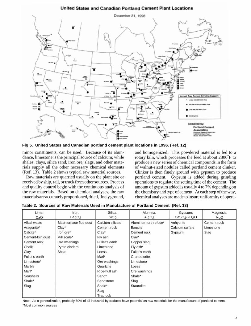
Manufacturing Portland CementPortland cement is a manufactured product. It is pro-duced in large, automated plants, which use naturallyoccurring and secondary raw materials. In 1996 therewere 118 portland cement plants in the United Stateshaving a total capacity of close to 76.0 million tons ofclinker per year (Ref. 12). A map with the cement plantlocations in the United States and Canada is shown inFigure 5.
The four primary chemical elements needed to produceportland cement are: calcium, silicon, aluminum, andiron. Calcium sulfate, usually added as gypsum, is alsorequired in the last stage of production. Almost any rawmaterial, which can supply these chemical elements abun-dantly and economically without containing deleterious
5
Note: As a generalization, probably 50% of all industrial byproducts have potential as raw materials for the manufacture of portland cement.*Most common sources
Lime,CaO
Iron,Fe2O3
Silica,SiO2
Alumina,Al2O3
Gypsum,CaSO4•2H2O
Magnesia,MgO
Alkali waste Blast-furnace flue dust Calcium silicate Aluminum-ore refuse* Anhydrite Cement rockAragonite* Clay* Cement rock Bauxite Calcium sulfate LimestoneCalcite* Iron ore* Clay* Cement rock Gypsum SlagCement-kiln dust Mill scale* Fly ash Clay*Cement rock Ore washings Fuller's earth Copper slagChalk Pyrite cinders Limestone Fly ash*Clay Shale Loess Fuller's earthFuller's earth Marl* GranodioriteLimestone* Ore washings LimestoneMarble Quartzite LoessMarl* Rice-hull ash Ore washingsSeashells Sand* Shale*Shale* Sandstone SlagSlag Shale* Staurolite
SlagTraprock
Table 2. Sources of Raw Materials Used in Manufacture of Portland Cement (Ref. 13)
minor constituents, can be used. Because of its abun-dance, limestone is the principal source of calcium, whileshales, clays, silica sand, iron ore, slags, and other mate-rials supply all the other necessary chemical elements(Ref. 13). Table 2 shows typical raw material sources.
Raw materials are quarried usually on the plant site orreceived by ship, rail, or truck from other sources. Processand quality control begin with the continuous analysis ofthe raw materials. Based on chemical analyses, the rawmaterials are accurately proportioned, dried, finely ground,
and homogenized. This powdered material is fed to arotary kiln, which processes the feed at about 2800
oF to
produce a new series of chemical compounds in the formof walnut-sized nodules called portland cement clinker.Clinker is then finely ground with gypsum to produceportland cement. Gypsum is added during grindingoperations to regulate the setting time of the cement. Theamount of gypsum added is usually 4 to 7% depending onthe chemistry and type of cement. At each step of the way,chemical analyses are made to insure uniformity of opera-
Fig 5. United States and Canadian portland cement plant locations in 1996. (Ref. 12)
6
Portland Cement Chemistry
Compounds Formed in the Kiln
During the burning operation in the manufacture of port-land cement clinker, calcium oxide combines with theacidic components (alumina, silica, and iron oxides) ofthe raw mix to form four principal compounds that makeup about 95% of the clinker by weight. The primarycompounds and their abbreviations are as follows:
Tricalcium silicate C3S *
Dicalcium silicate C2S
Tricalcium aluminate C3A
Tetracalcium aluminoferrite C4AF
The following properties are associated with the fourprimary cement compounds:
Tricalcium Silicate, C3S, hydrates and hardens rap-
idly and is largely responsible for initial set and earlystrength. In general, the early strength of portlandcement concrete is higher with increased percentagesof C
3S.
Dicalcium Silicate, C2S, hydrates and hardens slowly
and contributes largely to strength increase at agesbeyond one week.
Tricalcium Aluminate, C3A, liberates a large amount
of heat during the first few days of hydration andhardening. It also contributes slightly to early strengthdevelopment. Gypsum, added during final cementgrinding, slows down the hydration rate of C
3A.
Without gypsum, a cement with C3A present would
set rapidly. Cements with low percentages of C3A are
especially resistant to sulfates contained in wastes orsoils.
Tetracalcium aluminoferrite, C4AF, reduces the
clinkering temperature, thereby assisting in the manu-facture of cement. It hydrates rather rapidly butcontributes very little to strength.
C3S and C
2S in clinker and cement are also referred to as
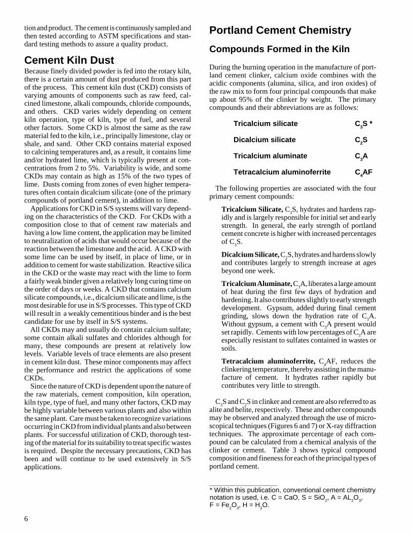
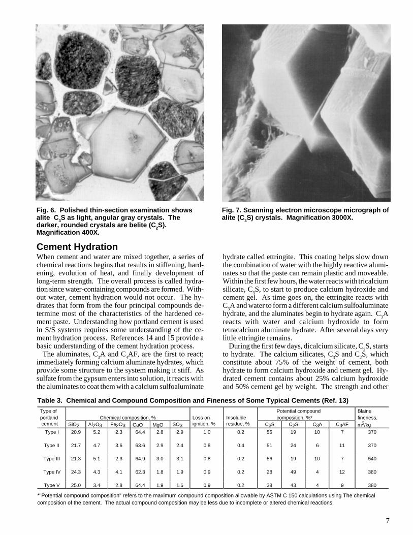
alite and belite, respectively. These and other compoundsmay be observed and analyzed through the use of micro-scopical techniques (Figures 6 and 7) or X-ray diffractiontechniques. The approximate percentage of each com-pound can be calculated from a chemical analysis of theclinker or cement. Table 3 shows typical compoundcomposition and fineness for each of the principal types ofportland cement.
__________________* Within this publication, conventional cement chemistrynotation is used, i.e. C = CaO, S = SiO
2, A = AL
2O
3,
F = Fe2O
3, H = H
2O.
tion and product. The cement is continuously sampled andthen tested according to ASTM specifications and stan-dard testing methods to assure a quality product.
Cement Kiln DustBecause finely divided powder is fed into the rotary kiln,there is a certain amount of dust produced from this partof the process. This cement kiln dust (CKD) consists ofvarying amounts of components such as raw feed, cal-cined limestone, alkali compounds, chloride compounds,and others. CKD varies widely depending on cementkiln operation, type of kiln, type of fuel, and severalother factors. Some CKD is almost the same as the rawmaterial fed to the kiln, i.e., principally limestone, clay orshale, and sand. Other CKD contains material exposedto calcining temperatures and, as a result, it contains limeand/or hydrated lime, which is typically present at con-centrations from 2 to 5%. Variability is wide, and someCKDs may contain as high as 15% of the two types oflime. Dusts coming from zones of even higher tempera-tures often contain dicalcium silicate (one of the primarycompounds of portland cement), in addition to lime.
Applications for CKD in S/S systems will vary depend-ing on the characteristics of the CKD. For CKDs with acomposition close to that of cement raw materials andhaving a low lime content, the application may be limitedto neutralization of acids that would occur because of thereaction between the limestone and the acid. A CKD withsome lime can be used by itself, in place of lime, or inaddition to cement for waste stabilization. Reactive silicain the CKD or the waste may react with the lime to forma fairly weak binder given a relatively long curing time onthe order of days or weeks. A CKD that contains calciumsilicate compounds, i.e., dicalcium silicate and lime, is themost desirable for use in S/S processes. This type of CKDwill result in a weakly cementitious binder and is the bestcandidate for use by itself in S/S systems.
All CKDs may and usually do contain calcium sulfate;some contain alkali sulfates and chlorides although formany, these compounds are present at relatively lowlevels. Variable levels of trace elements are also presentin cement kiln dust. These minor components may affectthe performance and restrict the applications of someCKDs.
Since the nature of CKD is dependent upon the nature ofthe raw materials, cement composition, kiln operation,kiln type, type of fuel, and many other factors, CKD maybe highly variable between various plants and also withinthe same plant. Care must be taken to recognize variationsoccurring in CKD from individual plants and also betweenplants. For successful utilization of CKD, thorough test-ing of the material for its suitability to treat specific wastesis required. Despite the necessary precautions, CKD hasbeen and will continue to be used extensively in S/Sapplications.
7
*"Potential compound composition" refers to the maximum compound composition allowable by ASTM C 150 calculations using The chemicalcomposition of the cement. The actual compound composition may be less due to incomplete or altered chemical reactions.
Type ofportland Chemical composition, % Loss on Insoluble
Potential compound composition, %*
Blainefineness,
cement SiO2 Al2O3 Fe2O3 CaO MgO SO3 ignition, % residue, % C3S C2S C3A C4AF m2/kgType I 20.9 5.2 2.3 64.4 2.8 2.9 1.0 0.2 55 19 10 7 370
Type II 21.7 4.7 3.6 63.6 2.9 2.4 0.8 0.4 51 24 6 11 370
Type III 21.3 5.1 2.3 64.9 3.0 3.1 0.8 0.2 56 19 10 7 540
Type IV 24.3 4.3 4.1 62.3 1.8 1.9 0.9 0.2 28 49 4 12 380
Type V 25.0 3.4 2.8 64.4 1.9 1.6 0.9 0.2 38 43 4 9 380
Table 3. Chemical and Compound Composition and Fineness of Some Typical Cements (Ref. 13)
Fig. 6. Polished thin-section examination showsalite C3S as light, angular gray crystals. Thedarker, rounded crystals are belite (C2S).Magnification 400X.
Fig. 7. Scanning electron microscope micrograph ofalite (C3S) crystals. Magnification 3000X.
hydrate called ettringite. This coating helps slow downthe combination of water with the highly reactive alumi-nates so that the paste can remain plastic and moveable.Within the first few hours, the water reacts with tricalciumsilicate, C
3S, to start to produce calcium hydroxide and
cement gel. As time goes on, the ettringite reacts withC
3A and water to form a different calcium sulfoaluminate
hydrate, and the aluminates begin to hydrate again. C3A
reacts with water and calcium hydroxide to formtetracalcium aluminate hydrate. After several days verylittle ettringite remains.
During the first few days, dicalcium silicate, C2S, starts
to hydrate. The calcium silicates, C3S and C
2S, which
constitute about 75% of the weight of cement, bothhydrate to form calcium hydroxide and cement gel. Hy-drated cement contains about 25% calcium hydroxideand 50% cement gel by weight. The strength and other
Cement HydrationWhen cement and water are mixed together, a series ofchemical reactions begins that results in stiffening, hard-ening, evolution of heat, and finally development oflong-term strength. The overall process is called hydra-tion since water-containing compounds are formed. With-out water, cement hydration would not occur. The hy-drates that form from the four principal compounds de-termine most of the characteristics of the hardened ce-ment paste. Understanding how portland cement is usedin S/S systems requires some understanding of the ce-ment hydration process. References 14 and 15 provide abasic understanding of the cement hydration process.
The aluminates, C3A and C
4AF, are the first to react;
immediately forming calcium aluminate hydrates, whichprovide some structure to the system making it stiff. Assulfate from the gypsum enters into solution, it reacts withthe aluminates to coat them with a calcium sulfoaluminate
8
properties of hydrated cement are due primarily to cementgel. The cement gel acts as the principal binder andhardener in the portland cement/water system. The pri-mary hydration reactions (compound transformations)are shown in Table 4.
Cement gel, one of the major products of cement hydra-tion, is also referred to as calcium silicate hydrate (CSH)or tobermorite gel. This gel is a nearly amorphous(uncrystallized) material with lime to silica to water ratiosclose to the 3/2/3 as shown in Table 4. In fact, these ratiosare approximate and will vary depending on the amount ofwater and the particular cement used to make thecementitious solid. Because of the variability of thecomposition, the notation for calcium silicate hydrate isusually not written as C
3S
2H
3 to emphasize that the ratios
are not exact.The chemical reactions between the cement and the
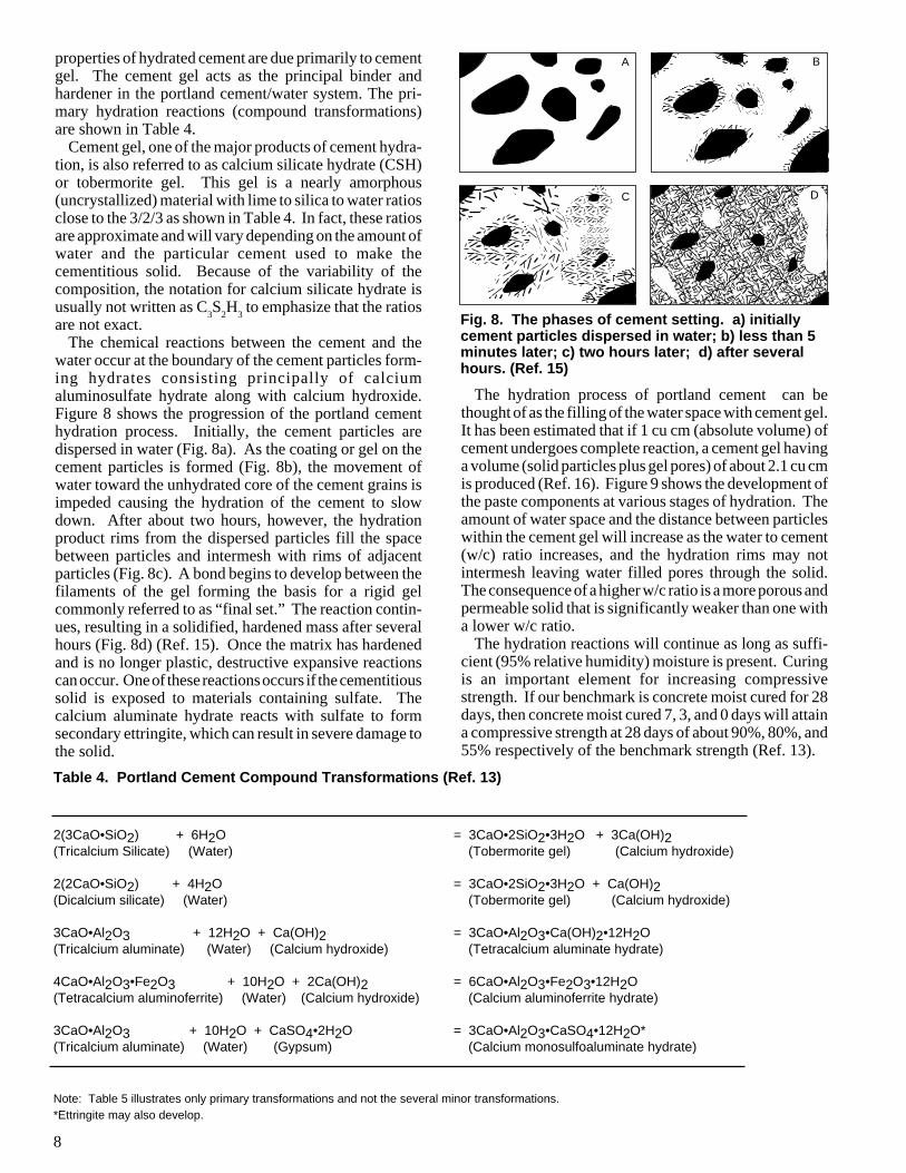
water occur at the boundary of the cement particles form-ing hydrates consisting principally of calciumaluminosulfate hydrate along with calcium hydroxide.Figure 8 shows the progression of the portland cementhydration process. Initially, the cement particles aredispersed in water (Fig. 8a). As the coating or gel on thecement particles is formed (Fig. 8b), the movement ofwater toward the unhydrated core of the cement grains isimpeded causing the hydration of the cement to slowdown. After about two hours, however, the hydrationproduct rims from the dispersed particles fill the spacebetween particles and intermesh with rims of adjacentparticles (Fig. 8c). A bond begins to develop between thefilaments of the gel forming the basis for a rigid gelcommonly referred to as “final set.” The reaction contin-ues, resulting in a solidified, hardened mass after severalhours (Fig. 8d) (Ref. 15). Once the matrix has hardenedand is no longer plastic, destructive expansive reactionscan occur. One of these reactions occurs if the cementitioussolid is exposed to materials containing sulfate. Thecalcium aluminate hydrate reacts with sulfate to formsecondary ettringite, which can result in severe damage tothe solid.
Note: Table 5 illustrates only primary transformations and not the several minor transformations.*Ettringite may also develop.
Fig. 8. The phases of cement setting. a) initiallycement particles dispersed in water; b) less than 5minutes later; c) two hours later; d) after severalhours. (Ref. 15)
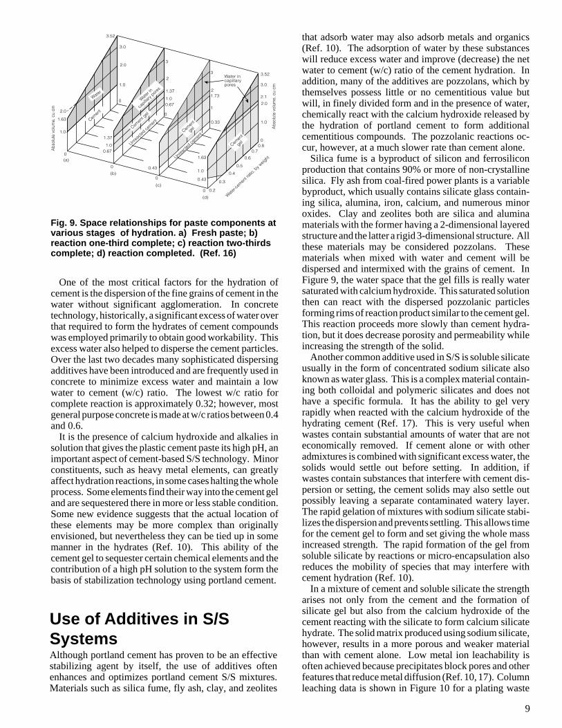
The hydration process of portland cement can bethought of as the filling of the water space with cement gel.It has been estimated that if 1 cu cm (absolute volume) ofcement undergoes complete reaction, a cement gel havinga volume (solid particles plus gel pores) of about 2.1 cu cmis produced (Ref. 16). Figure 9 shows the development ofthe paste components at various stages of hydration. Theamount of water space and the distance between particleswithin the cement gel will increase as the water to cement(w/c) ratio increases, and the hydration rims may notintermesh leaving water filled pores through the solid.The consequence of a higher w/c ratio is a more porous andpermeable solid that is significantly weaker than one witha lower w/c ratio.
The hydration reactions will continue as long as suffi-cient (95% relative humidity) moisture is present. Curingis an important element for increasing compressivestrength. If our benchmark is concrete moist cured for 28days, then concrete moist cured 7, 3, and 0 days will attaina compressive strength at 28 days of about 90%, 80%, and55% respectively of the benchmark strength (Ref. 13).
Table 4. Portland Cement Compound Transformations (Ref. 13)
A
C D
B
2(3CaO•SiO2) + 6H2O = 3CaO•2SiO2•3H2O + 3Ca(OH)2(Tricalcium Silicate) (Water) (Tobermorite gel) (Calcium hydroxide)
2(2CaO•SiO2) + 4H2O = 3CaO•2SiO2•3H2O + Ca(OH)2(Dicalcium silicate) (Water) (Tobermorite gel) (Calcium hydroxide)
3CaO•Al2O3 + 12H2O + Ca(OH)2 = 3CaO•Al2O3•Ca(OH)2•12H2O(Tricalcium aluminate) (Water) (Calcium hydroxide) (Tetracalcium aluminate hydrate)
4CaO•Al2O3•Fe2O3 + 10H2O + 2Ca(OH)2 = 6CaO•Al2O3•Fe2O3•12H2O(Tetracalcium aluminoferrite) (Water) (Calcium hydroxide) (Calcium aluminoferrite hydrate)
3CaO•Al2O3 + 10H2O + CaSO4•2H2O = 3CaO•Al2O3•CaSO4•12H2O*(Tricalcium aluminate) (Water) (Gypsum) (Calcium monosulfoaluminate hydrate)
9
that adsorb water may also adsorb metals and organics(Ref. 10). The adsorption of water by these substanceswill reduce excess water and improve (decrease) the netwater to cement (w/c) ratio of the cement hydration. Inaddition, many of the additives are pozzolans, which bythemselves possess little or no cementitious value butwill, in finely divided form and in the presence of water,chemically react with the calcium hydroxide released bythe hydration of portland cement to form additionalcementitious compounds. The pozzolanic reactions oc-cur, however, at a much slower rate than cement alone.
Silica fume is a byproduct of silicon and ferrosiliconproduction that contains 90% or more of non-crystallinesilica. Fly ash from coal-fired power plants is a variablebyproduct, which usually contains silicate glass contain-ing silica, alumina, iron, calcium, and numerous minoroxides. Clay and zeolites both are silica and aluminamaterials with the former having a 2-dimensional layeredstructure and the latter a rigid 3-dimensional structure. Allthese materials may be considered pozzolans. Thesematerials when mixed with water and cement will bedispersed and intermixed with the grains of cement. InFigure 9, the water space that the gel fills is really watersaturated with calcium hydroxide. This saturated solutionthen can react with the dispersed pozzolanic particlesforming rims of reaction product similar to the cement gel.This reaction proceeds more slowly than cement hydra-tion, but it does decrease porosity and permeability whileincreasing the strength of the solid.
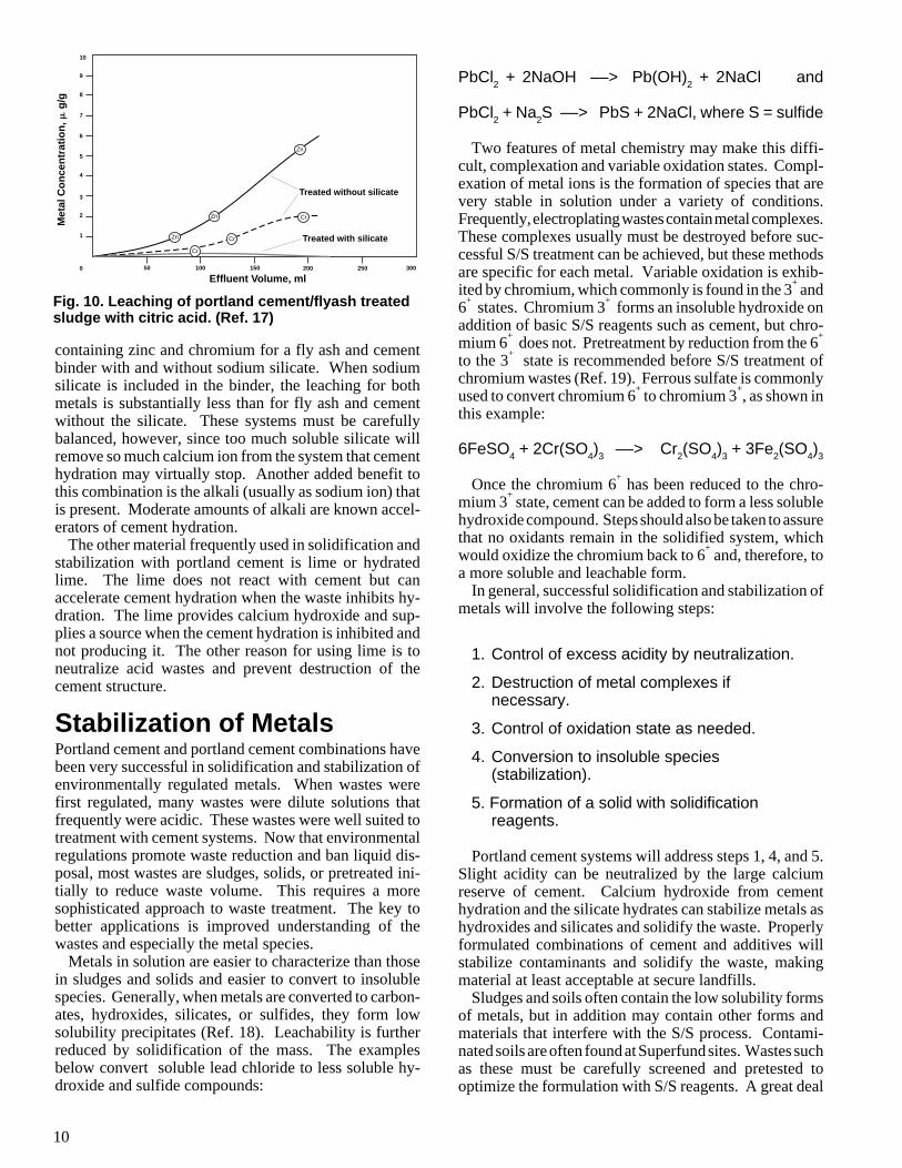
Another common additive used in S/S is soluble silicateusually in the form of concentrated sodium silicate alsoknown as water glass. This is a complex material contain-ing both colloidal and polymeric silicates and does nothave a specific formula. It has the ability to gel veryrapidly when reacted with the calcium hydroxide of thehydrating cement (Ref. 17). This is very useful whenwastes contain substantial amounts of water that are noteconomically removed. If cement alone or with otheradmixtures is combined with significant excess water, thesolids would settle out before setting. In addition, ifwastes contain substances that interfere with cement dis-persion or setting, the cement solids may also settle outpossibly leaving a separate contaminated watery layer.The rapid gelation of mixtures with sodium silicate stabi-lizes the dispersion and prevents settling. This allows timefor the cement gel to form and set giving the whole massincreased strength. The rapid formation of the gel fromsoluble silicate by reactions or micro-encapsulation alsoreduces the mobility of species that may interfere withcement hydration (Ref. 10).
In a mixture of cement and soluble silicate the strengtharises not only from the cement and the formation ofsilicate gel but also from the calcium hydroxide of thecement reacting with the silicate to form calcium silicatehydrate. The solid matrix produced using sodium silicate,however, results in a more porous and weaker materialthan with cement alone. Low metal ion leachability isoften achieved because precipitates block pores and otherfeatures that reduce metal diffusion (Ref. 10, 17). Columnleaching data is shown in Figure 10 for a plating waste
Use of Additives in S/SSystemsAlthough portland cement has proven to be an effectivestabilizing agent by itself, the use of additives oftenenhances and optimizes portland cement S/S mixtures.Materials such as silica fume, fly ash, clay, and zeolites
Fig. 9. Space relationships for paste components atvarious stages of hydration. a) Fresh paste; b)reaction one-third complete; c) reaction two-thirdscomplete; d) reaction completed. (Ref. 16)
One of the most critical factors for the hydration ofcement is the dispersion of the fine grains of cement in thewater without significant agglomeration. In concretetechnology, historically, a significant excess of water overthat required to form the hydrates of cement compoundswas employed primarily to obtain good workability. Thisexcess water also helped to disperse the cement particles.Over the last two decades many sophisticated dispersingadditives have been introduced and are frequently used inconcrete to minimize excess water and maintain a lowwater to cement (w/c) ratio. The lowest w/c ratio forcomplete reaction is approximately 0.32; however, mostgeneral purpose concrete is made at w/c ratios between 0.4and 0.6.
It is the presence of calcium hydroxide and alkalies insolution that gives the plastic cement paste its high pH, animportant aspect of cement-based S/S technology. Minorconstituents, such as heavy metal elements, can greatlyaffect hydration reactions, in some cases halting the wholeprocess. Some elements find their way into the cement geland are sequestered there in more or less stable condition.Some new evidence suggests that the actual location ofthese elements may be more complex than originallyenvisioned, but nevertheless they can be tied up in somemanner in the hydrates (Ref. 10). This ability of thecement gel to sequester certain chemical elements and thecontribution of a high pH solution to the system form thebasis of stabilization technology using portland cement.
Abs
olut
e vo
lum
e, c
u cm
Abs
olut
e vo
lum
e, c
u cm
Water-c
emen
t rati
o, by w
eight
Water incapillarypores
Water
Water in
capilla
ry por
es
Cemen
t
gel
Cemen
t
gel
Cemen
t gel
Cemen
t
Unrea
cted ce
ment
3.52
3.52
3.0
3.0
2.0
2.0
2.0
1.0
1.0
1.0
1.0
0
0
0
0
0
0
0
0.33
1
1.732
3
3
2
2.1
1.63
1.63
0.43
0.80.7
0.6
0.5
0.4
0.3
0.2
(a)
(b)
(c)
(d)
1.37
1.00.67
1.37
1.00.67
0.43
➤
➤
Unrea
cted ce
ment
10
PbCl2 + 2NaOH ––> Pb(OH)2 + 2NaCl and
PbCl2 + Na2S ––> PbS + 2NaCl, where S = sulfide
Two features of metal chemistry may make this diffi-cult, complexation and variable oxidation states. Compl-exation of metal ions is the formation of species that arevery stable in solution under a variety of conditions.Frequently, electroplating wastes contain metal complexes.These complexes usually must be destroyed before suc-cessful S/S treatment can be achieved, but these methodsare specific for each metal. Variable oxidation is exhib-ited by chromium, which commonly is found in the 3
+ and
6+ states. Chromium 3
+ forms an insoluble hydroxide on
addition of basic S/S reagents such as cement, but chro-mium 6
+ does not. Pretreatment by reduction from the 6
+
to the 3+ state is recommended before S/S treatment of
chromium wastes (Ref. 19). Ferrous sulfate is commonlyused to convert chromium 6
+ to chromium 3
+, as shown in
this example:
6FeSO4 + 2Cr(SO4)3 ––> Cr2(SO4)3 + 3Fe2(SO4)3
Once the chromium 6+ has been reduced to the chro-
mium 3+ state, cement can be added to form a less soluble
hydroxide compound. Steps should also be taken to assurethat no oxidants remain in the solidified system, whichwould oxidize the chromium back to 6
+ and, therefore, to
a more soluble and leachable form.In general, successful solidification and stabilization of
metals will involve the following steps:
1. Control of excess acidity by neutralization.
2. Destruction of metal complexes ifnecessary.
3. Control of oxidation state as needed.
4. Conversion to insoluble species(stabilization).
5. Formation of a solid with solidificationreagents.
Portland cement systems will address steps 1, 4, and 5.Slight acidity can be neutralized by the large calciumreserve of cement. Calcium hydroxide from cementhydration and the silicate hydrates can stabilize metals ashydroxides and silicates and solidify the waste. Properlyformulated combinations of cement and additives willstabilize contaminants and solidify the waste, makingmaterial at least acceptable at secure landfills.
Sludges and soils often contain the low solubility formsof metals, but in addition may contain other forms andmaterials that interfere with the S/S process. Contami-nated soils are often found at Superfund sites. Wastes suchas these must be carefully screened and pretested tooptimize the formulation with S/S reagents. A great deal
Fig. 10. Leaching of portland cement/flyash treatedsludge with citric acid. (Ref. 17)
containing zinc and chromium for a fly ash and cementbinder with and without sodium silicate. When sodiumsilicate is included in the binder, the leaching for bothmetals is substantially less than for fly ash and cementwithout the silicate. These systems must be carefullybalanced, however, since too much soluble silicate willremove so much calcium ion from the system that cementhydration may virtually stop. Another added benefit tothis combination is the alkali (usually as sodium ion) thatis present. Moderate amounts of alkali are known accel-erators of cement hydration.
The other material frequently used in solidification andstabilization with portland cement is lime or hydratedlime. The lime does not react with cement but canaccelerate cement hydration when the waste inhibits hy-dration. The lime provides calcium hydroxide and sup-plies a source when the cement hydration is inhibited andnot producing it. The other reason for using lime is toneutralize acid wastes and prevent destruction of thecement structure.
Stabilization of MetalsPortland cement and portland cement combinations havebeen very successful in solidification and stabilization ofenvironmentally regulated metals. When wastes werefirst regulated, many wastes were dilute solutions thatfrequently were acidic. These wastes were well suited totreatment with cement systems. Now that environmentalregulations promote waste reduction and ban liquid dis-posal, most wastes are sludges, solids, or pretreated ini-tially to reduce waste volume. This requires a moresophisticated approach to waste treatment. The key tobetter applications is improved understanding of thewastes and especially the metal species.
Metals in solution are easier to characterize than thosein sludges and solids and easier to convert to insolublespecies. Generally, when metals are converted to carbon-ates, hydroxides, silicates, or sulfides, they form lowsolubility precipitates (Ref. 18). Leachability is furtherreduced by solidification of the mass. The examplesbelow convert soluble lead chloride to less soluble hy-droxide and sulfide compounds:
Cr
Zn
Cr
Zn
Cr
Zn
0 50 100 200150 250 300
1
2
3
4
5
6
7
8
9
10M
etal
Co
nce
ntr
atio
n, �
g/g
Effluent Volume, ml
Treated without silicate
Treated with silicate
11
For those cases where pretreatment is needed, the solu-tions are usually different for different wastes or metalspecies. In this section some suggestions and examplesare discussed for individual metals. These ideas are onlya sampling of possible approaches and pretreatments forwastes that are difficult to stabilize usually due to highmetal concentrations.
Among the RCRA metals, barium is one of the easiestto handle because relatively insoluble barium sulfate iseasily formed, and it is stable in an alkaline environment.Cadmium is also comparatively easy to handle as long asit is not complexed. In portland cement-based S/S sys-tems, cadmium forms hydroxides and silicates that remainrelatively stable as long as the pH remains high. Thesystem pH will remain high as long as sufficient cement isused in the formulation.
Selenium and silver apparently are stabilized well inportland cement-based systems; however, there is littleinformation at high concentrations. Silver is valuableenough so almost all waste streams have been pretreatedto recover the metal leaving low concentrations in theremaining waste. Addition of chloride to form silverchloride in the S/S binder is usually sufficient to reducesilver leaching to levels below regulatory concern. Sele-nium is rarely found in significant concentrations in wastes.Selenium behaves like sulfur and forms many very slightlysoluble compounds with heavy metals, which may be thereason its level is so low in leachates.
Chromium has been discussed previously where it waspointed out that in the 3
+ oxidation state a very slightly
soluble hydroxide is formed, which is stabilized well incement-based systems. Some evidence suggests (Ref. 20)a stable chromium silicate complex may form. Electro-plating wastes often contain chromium complexes, whichmust be destroyed first (Ref. 18). Chromium leachingfrom S/S wastes should not be a problem as long asnothing in the solidified waste destabilizes the 3
+ state of
the chromium.Copper, nickel, and zinc are not RCRA metals but are
regulated either by other federal regulations or by certainstates. These metals all form sulfides that have very lowsolubility and are stable at high pH such as that found inportland cement solidified wastes. In some instances, theformation of the sulfides may be impractical or too costly.These metals all have low solubility hydroxides, but theminimum occurs in a fairly narrow range of pH.
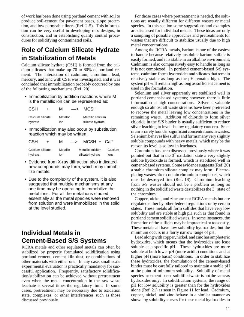
Lead along with copper, nickel, and zinc has amphoterichydroxides, which means that the hydroxides are leastsoluble at a specific pH. These hydroxides are moresoluble at both lower pH (more acidic) conditions and athigher pH (more basic) conditions. In order to stabilizethese hydroxides, the formulation of the cement-basedbinder must be carefully tailored to maintain a stable pHat the point of minimum solubility. Solubility of metalspecies in cement-based solidified waste is not the same ashydroxides only. In solidification systems, the range ofpH for low solubility is greater than for the hydroxidesalone (Ref. 21) as seen in Figure 11 for lead. Cadmium,copper, nickel, and zinc behave in a similar manner asshown by solubility curves for these metal hydroxides in
of work has been done using portland cement with soil toproduce soil-cement for pavement bases, slope protec-tion, and low permeable liners (Ref. 2-5). This informa-tion can be very useful in developing mix designs, inconstruction, and in establishing quality control proce-dures for solidifying contaminated soils.
Role of Calcium Silicate Hydratein Stabilization of MetalsCalcium silicate hydrate (CSH) is formed from the cal-cium silicates that make up 70 to 80% of portland ce-ment. The interaction of cadmium, chromium, lead,mercury, and zinc with CSH was investigated, and it wasconcluded that immobilization probably occurred by oneof the following mechanisms (Ref. 20):
• Immobilization by addition reactions where Mis the metallic ion can be represented as:
CSH + M ––> MCSH
Calcium silicate Metallic Metallic calcium
hydrate ion silicate hydrate
• Immobilization may also occur by substitutionreaction which may be written:
CSH + M ––> MCSH + Ca++
Calcium silicate Metallic Metallic calcium Calcium
hydrate ion silicate hydrate ions
• Evidence from X-ray diffraction also indicatednew compounds may form, which may immobi-lize metals.
• Due to the complexity of the system, it is alsosuggested that multiple mechanisms at anyone time may be operating to immobilize themetal ions. For all the metal ions studied,essentially all the metal species were removedfrom solution and were immobilized in the solidat the level studied.
Individual Metals inCement-Based S/S SystemsRCRA metals and other regulated metals can often bestabilized by properly formulated solidification usingportland cement, cement kiln dust, or combinations ofother materials with either one. In any case, small scaleexperimental evaluation is practically mandatory for suc-cessful application. Frequently, satisfactory solidifica-tion/stabilization can be achieved without pretreatmenteven when the metal concentration in the raw wasteleachate is several times the regulatory limit. In somecases, pretreatment may be necessary due to oxidationstate, complexes, or other interferences such as thosediscussed previously.
12
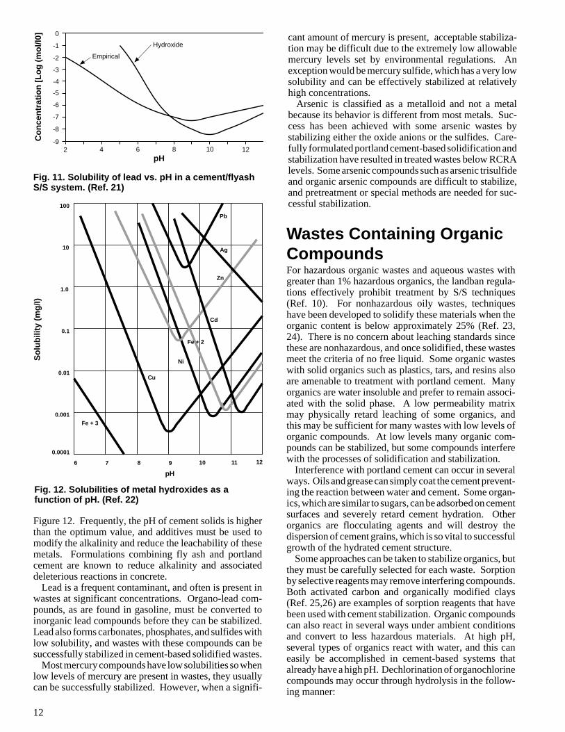
Fig. 12. Solubilities of metal hydroxides as afunction of pH. (Ref. 22)
Figure 12. Frequently, the pH of cement solids is higherthan the optimum value, and additives must be used tomodify the alkalinity and reduce the leachability of thesemetals. Formulations combining fly ash and portlandcement are known to reduce alkalinity and associateddeleterious reactions in concrete.
Lead is a frequent contaminant, and often is present inwastes at significant concentrations. Organo-lead com-pounds, as are found in gasoline, must be converted toinorganic lead compounds before they can be stabilized.Lead also forms carbonates, phosphates, and sulfides withlow solubility, and wastes with these compounds can besuccessfully stabilized in cement-based solidified wastes.
Most mercury compounds have low solubilities so whenlow levels of mercury are present in wastes, they usuallycan be successfully stabilized. However, when a signifi-
cant amount of mercury is present, acceptable stabiliza-tion may be difficult due to the extremely low allowablemercury levels set by environmental regulations. Anexception would be mercury sulfide, which has a very lowsolubility and can be effectively stabilized at relativelyhigh concentrations.
Arsenic is classified as a metalloid and not a metalbecause its behavior is different from most metals. Suc-cess has been achieved with some arsenic wastes bystabilizing either the oxide anions or the sulfides. Care-fully formulated portland cement-based solidification andstabilization have resulted in treated wastes below RCRAlevels. Some arsenic compounds such as arsenic trisulfideand organic arsenic compounds are difficult to stabilize,and pretreatment or special methods are needed for suc-cessful stabilization.
Wastes Containing OrganicCompoundsFor hazardous organic wastes and aqueous wastes withgreater than 1% hazardous organics, the landban regula-tions effectively prohibit treatment by S/S techniques(Ref. 10). For nonhazardous oily wastes, techniqueshave been developed to solidify these materials when theorganic content is below approximately 25% (Ref. 23,24). There is no concern about leaching standards sincethese are nonhazardous, and once solidified, these wastesmeet the criteria of no free liquid. Some organic wasteswith solid organics such as plastics, tars, and resins alsoare amenable to treatment with portland cement. Manyorganics are water insoluble and prefer to remain associ-ated with the solid phase. A low permeability matrixmay physically retard leaching of some organics, andthis may be sufficient for many wastes with low levels oforganic compounds. At low levels many organic com-pounds can be stabilized, but some compounds interferewith the processes of solidification and stabilization.
Interference with portland cement can occur in severalways. Oils and grease can simply coat the cement prevent-ing the reaction between water and cement. Some organ-ics, which are similar to sugars, can be adsorbed on cementsurfaces and severely retard cement hydration. Otherorganics are flocculating agents and will destroy thedispersion of cement grains, which is so vital to successfulgrowth of the hydrated cement structure.
Some approaches can be taken to stabilize organics, butthey must be carefully selected for each waste. Sorptionby selective reagents may remove interfering compounds.Both activated carbon and organically modified clays(Ref. 25,26) are examples of sorption reagents that havebeen used with cement stabilization. Organic compoundscan also react in several ways under ambient conditionsand convert to less hazardous materials. At high pH,several types of organics react with water, and this caneasily be accomplished in cement-based systems thatalready have a high pH. Dechlorination of organochlorinecompounds may occur through hydrolysis in the follow-ing manner:
100
10
1.0
0.1
0.01
0.001
0.0001
6 7 8 9 10 11 12
pH
Fe + 3
Cu
Ni
Fe + 2
Cd
Zn
Ag
Pb
-1
0
-2
-3
-4
-5
-6
-7
-8
-92 4 6 8 10 12
Empirical
HydroxideC
on
cen
trat
ion
[L
og
(m
ol/l
0]
Fig. 11. Solubility of lead vs. pH in a cement/flyashS/S system. (Ref. 21)
pH
So
lub
ility
(m
g/I)
13
2 RCl5OH + Ca(OH)2 ––> 2 R´HCl4O2H + CaCl2 where R and R´ are part of organic molecules
Some calcium salts are less soluble than the organiccompounds so salt formation may reduce solubility. Forinstance, oxalic acid will form the salt, calcium oxalate,which is less soluble. Introduction of oxidants into the S/S system may also be effective in converting organics tonew compounds. Some alcohols can be oxidized byhydrogen peroxide to form an organic acid:
RCH2OH + 2H2O2 ––> RCOOH + 3H2O
The acid may then form a calcium salt. In all cases ofreactions, these must be carefully selected for undesirablereactions could occur with other components of the waste.The possibility exists that a metal could become moresoluble or that a hazardous organic compound could beformed by a side reaction.
Many organics are destroyed by incineration. However,being part of a waste stream, there inevitably will be someash left as a residue from many wastes. Portland cement-based stabilization and solidification may frequently bethe best means of treating these waste residues. Theseashes may often be easier to treat by S/S than some of theother wastes previously discussed.
Waste Components CausingInterferenceAs previously mentioned, waste compounds can inter-face with cement hydration, structure, or solidification.Individual studies usually examine the effect of one com-ponent at a time, and this is the basis of most of theinformation. Real wastes may have many components
* At high concentrations † Ratio of Fe+2 to Fe+3 important‡ Only in certain forms § By weight
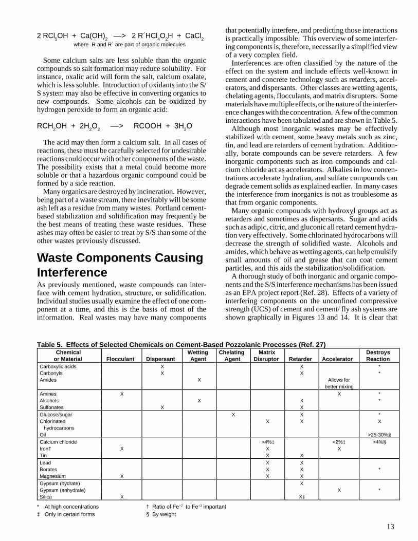
Table 5. Effects of Selected Chemicals on Cement-Based Pozzolanic Processes (Ref. 27)Chemical
or Material Flocculant DispersantWettingAgent
ChelatingAgent
MatrixDisruptor Retarder Accelerator
DestroysReaction
Carboxylic acids X X *Carbonyls X X *Amides X Allows for
better mixingAmines X X *Alcohols X X *Sulfonates X XGlucose/sugar X X *Chlorinated X X X hydrocarbonsOil >25-30%§Calcium chloride >4%‡ <2%‡ >4%§Iron† X X XTin X XLead X XBorates X X *Magnesium X X XGypsum (hydrate) XGypsum (anhydrate) X *Silica X X‡
that potentially interfere, and predicting those interactionsis practically impossible. This overview of some interfer-ing components is, therefore, necessarily a simplified viewof a very complex field.
Interferences are often classified by the nature of theeffect on the system and include effects well-known incement and concrete technology such as retarders, accel-erators, and dispersants. Other classes are wetting agents,chelating agents, flocculants, and matrix disrupters. Somematerials have multiple effects, or the nature of the interfer-ence changes with the concentration. A few of the commoninteractions have been tabulated and are shown in Table 5.
Although most inorganic wastes may be effectivelystabilized with cement, some heavy metals such as zinc,tin, and lead are retarders of cement hydration. Addition-ally, borate compounds can be severe retarders. A fewinorganic components such as iron compounds and cal-cium chloride act as accelerators. Alkalies in low concen-trations accelerate hydration, and sulfate compounds candegrade cement solids as explained earlier. In many casesthe interference from inorganics is not as troublesome asthat from organic components.
Many organic compounds with hydroxyl groups act asretarders and sometimes as dispersants. Sugar and acidssuch as adipic, citric, and gluconic all retard cement hydra-tion very effectively. Some chlorinated hydrocarbons willdecrease the strength of solidified waste. Alcohols andamides, which behave as wetting agents, can help emulsifysmall amounts of oil and grease that can coat cementparticles, and this aids the stabilization/solidification.
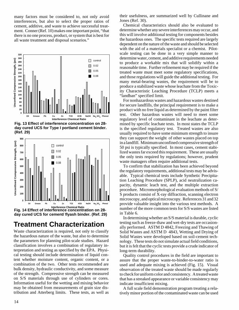
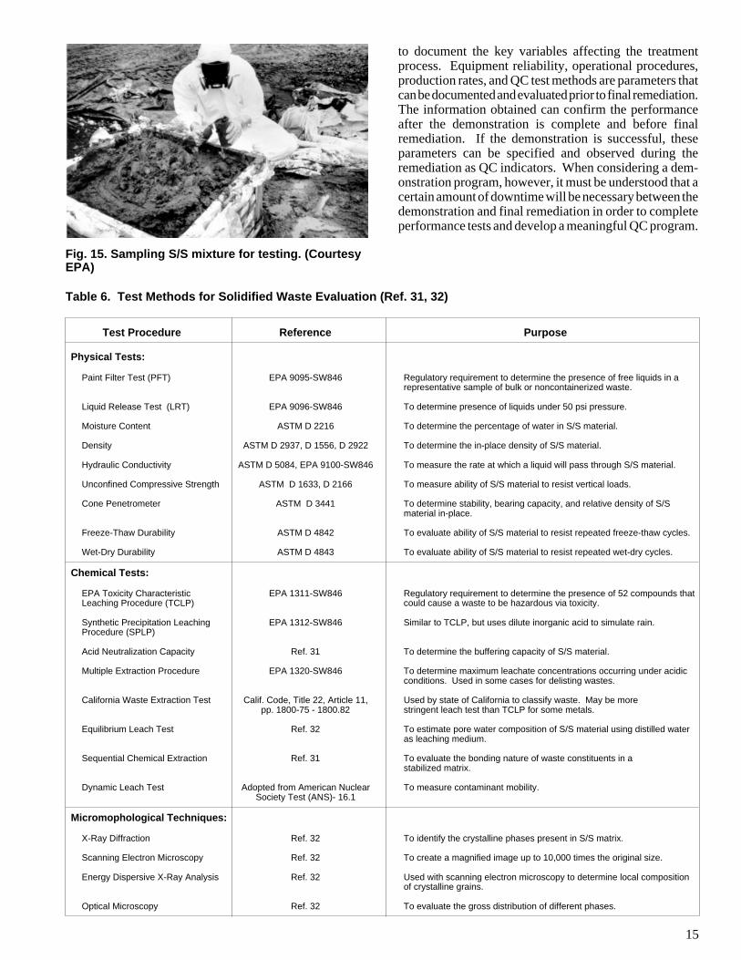
A thorough study of both inorganic and organic compo-nents and the S/S interference mechanisms has been issuedas an EPA project report (Ref. 28). Effects of a variety ofinterfering components on the unconfined compressivestrength (UCS) of cement and cement/ fly ash systems areshown graphically in Figures 13 and 14. It is clear that
14
their usefulness, are summarized well by Cullinane andJones (Ref. 30).
Chemical characteristics should also be evaluated todetermine whether any severe interferences may occur, andthis will involve additional testing for components besidesthe hazardous ones. The specific tests required are largelydependent on the nature of the waste and should be selectedwith the aid of a materials specialist or a chemist. Pilot-scale testing can be done in a very simple manner todetermine water, cement, and additive requirements neededto produce a workable mix that will solidify within areasonable time. Further refinement may be required if thetreated waste must meet some regulatory specifications,and those regulations will guide the additional testing. Formany metal-bearing wastes, the requirement will be toproduce a stabilized waste whose leachate from the Toxic-ity Characteristic Leaching Procedure (TCLP) meets a“landban” specified limit.
For nonhazardous wastes and hazardous wastes destinedfor secure landfills, the principal requirement is to make aproduct with no free liquid as determined by the paint filtertest. Other hazardous wastes will need to meet someregulatory level of contaminant in the leachate as deter-mined by specific leachate tests. In most states the TCLPis the specified regulatory test. Treated wastes are alsousually required to have some minimum strength to insurethey can support the weight of other wastes placed on topin a landfill. Minimum unconfined compressive strength of50 psi is typically specified. In most cases, cement stabi-lized wastes far exceed this requirement. These are usuallythe only tests required by regulations; however, prudentwaste managers often require additional tests.
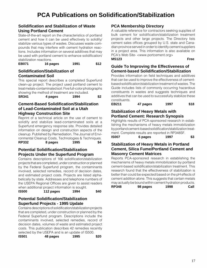
To confirm that stabilization has been achieved beyondthe regulatory requirements, additional tests may be advis-able. Typical chemical tests include Synthetic Precipita-tion Leaching Procedure (SPLP), acid neutralization ca-pacity, dynamic leach test, and the multiple extractionprocedure. Micromorphological evaluation methods of S/S products consist of X-ray diffraction, scanning electronmicroscopy, and optical microscopy. References 31 and 32provide valuable insight into the various test methods. Anumber of the more common tests for S/S wastes are listedin Table 6.
In determining whether an S/S material is durable, cyclictesting such as freeze-thaw and wet-dry tests are occasion-ally performed. ASTM D 4842, Freezing and Thawing ofSolid Wastes and ASTM D 4843, Wetting and Drying ofSolid Wastes were developed based on soil-cement tech-nology. These tests do not simulate actual field conditions,but it is felt that the cyclic tests provide a crude indicator oflong-term durability.
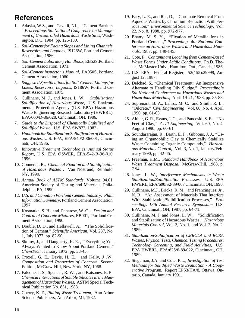
Quality control procedures in the field are important toassure that the proper waste-to-binder-to-water ratio isused and adequate mixing is achieved (Fig. 15). Visualobservation of the treated waste should be made regularlyto check for uniform color and consistency. A treated wastethat has a streaked appearance or variable consistency mayindicate insufficient mixing.
A full scale field demonstration program treating a rela-tively minor portion of the contaminated waste can be used
many factors must be considered to, not only avoidinterferences, but also to select the proper ratios ofcement, additive, and waste to achieve successful treat-ment. Conner (Ref. 10) makes one important point, “thatthere is no one process, product, or system that is best forall waste treatment and disposal scenarios.”
Oil Grease Pb Cu Zn TCE HCB NaOH Na2 SO4 Phenol
0
100
200
300
400
500
600
700
800
900
control
0.02
0.05
0.08
Interference Chemical Ratio
Un
co
nfi
ne
d C
om
pre
ss
ive
Str
en
gth
, (p
si)
Interference Chemical Ratio
Un
con
fin
ed C
om
pre
ssiv
e S
tren
gth
, (p
si)
Oil Grease Pb Cu Zn TCE HCB NaOH Na2 SO4 Phenol
0
20
40
60
80
100
120
140
160
180
200
220
240
260
280
300
320
control
0.02
0.05
0.08
Fig. 13 Effect of interference concentration on 28-day cured UCS for Type I portland cement binder.(Ref. 29)
Fig. 14 Effect of interference concentration on 28-day cured UCS for cement/ flyash binder. (Ref. 29)
Treatment CharacterizationWaste characterization is required, not only to classifythe hazardous nature of the waste, but also to determinethe parameters for planning pilot-scale studies. Hazardclassification involves a combination of regulatory in-terpretation and testing as specified by the EPA. Physi-cal testing should include determination of liquid con-tent whether moisture content, organic content, or acombination of the two. Other tests recommended arebulk density, hydraulic conductivity, and some measureof the strength. Compressive strength can be measuredon S/S materials through use of cylinders or cores.Information useful for the wetting and mixing behaviormay be obtained from measurements of grain size dis-tribution and Atterberg limits. These tests, as well as
15
Fig. 15. Sampling S/S mixture for testing. (CourtesyEPA)
to document the key variables affecting the treatmentprocess. Equipment reliability, operational procedures,production rates, and QC test methods are parameters thatcan be documented and evaluated prior to final remediation.The information obtained can confirm the performanceafter the demonstration is complete and before finalremediation. If the demonstration is successful, theseparameters can be specified and observed during theremediation as QC indicators. When considering a dem-onstration program, however, it must be understood that acertain amount of downtime will be necessary between thedemonstration and final remediation in order to completeperformance tests and develop a meaningful QC program.
Table 6. Test Methods for Solidified Waste Evaluation (Ref. 31, 32)
Test Procedure Reference Purpose
Physical Tests:
Paint Filter Test (PFT) EPA 9095-SW846 Regulatory requirement to determine the presence of free liquids in arepresentative sample of bulk or noncontainerized waste.
Liquid Release Test (LRT) EPA 9096-SW846 To determine presence of liquids under 50 psi pressure.
Moisture Content ASTM D 2216 To determine the percentage of water in S/S material.
Density ASTM D 2937, D 1556, D 2922 To determine the in-place density of S/S material.
Hydraulic Conductivity ASTM D 5084, EPA 9100-SW846 To measure the rate at which a liquid will pass through S/S material.
Unconfined Compressive Strength ASTM D 1633, D 2166 To measure ability of S/S material to resist vertical loads.
Cone Penetrometer ASTM D 3441 To determine stability, bearing capacity, and relative density of S/Smaterial in-place.
Freeze-Thaw Durability ASTM D 4842 To evaluate ability of S/S material to resist repeated freeze-thaw cycles.
Wet-Dry Durability ASTM D 4843 To evaluate ability of S/S material to resist repeated wet-dry cycles.
Chemical Tests:
EPA Toxicity Characteristic EPA 1311-SW846 Regulatory requirement to determine the presence of 52 compounds thatLeaching Procedure (TCLP) could cause a waste to be hazardous via toxicity.
Synthetic Precipitation Leaching EPA 1312-SW846 Similar to TCLP, but uses dilute inorganic acid to simulate rain.Procedure (SPLP)
Acid Neutralization Capacity Ref. 31 To determine the buffering capacity of S/S material.
Multiple Extraction Procedure EPA 1320-SW846 To determine maximum leachate concentrations occurring under acidicconditions. Used in some cases for delisting wastes.
California Waste Extraction Test Calif. Code, Title 22, Article 11, Used by state of California to classify waste. May be morepp. 1800-75 - 1800.82 stringent leach test than TCLP for some metals.
Equilibrium Leach Test Ref. 32 To estimate pore water composition of S/S material using distilled wateras leaching medium.
Sequential Chemical Extraction Ref. 31 To evaluate the bonding nature of waste constituents in astabilized matrix.
Dynamic Leach Test Adopted from American Nuclear To measure contaminant mobility.Society Test (ANS)- 16.1
Micromophological Techniques:
X-Ray Diffraction Ref. 32 To identify the crystalline phases present in S/S matrix.
Scanning Electron Microscopy Ref. 32 To create a magnified image up to 10,000 times the original size.
Energy Dispersive X-Ray Analysis Ref. 32 Used with scanning electron microscopy to determine local compositionof crystalline grains.
Optical Microscopy Ref. 32 To evaluate the gross distribution of different phases.
16
19. Eary, L. E., and Rai, D., “Chromate Removal FromAqueous Wastes by Chromium Reduction With Fer-rous Ion,” Environmental Science Technology, Vol.22, No. 8, 1988, pp. 972-977.
20. Bhatty, M. S. Y., “Fixation of Metallic Ions inPortland Cement.,” Proceedings 4th National Con-ference on Hazardous Wastes and Hazardous Mate-rials, 1987, pp. 140-145.
21. Cote, P., Contaminant Leaching from Cement-BasedWaste Forms Under Acidic Conditions, Ph.D. The-sis, McMaster Univ., Hamilton, Ont., Canada, 1986.
22. U.S. EPA, Federal Register, 52(155):29999, Au-gust 12, 1987.
23. Delchad, S., “Chemical Treatment: An InexpensiveAlternate to Handling Oily Sludge,” Proceeding’s5th National Conference on Hazardous Wastes andHazardous Materials, April 19-21, 1988, pp. 85-88.
24. Suprenant, B. A., Lahrs,, M. C. and Smith, R. L.,“Oilcrete,” Civil Engineering Vol. 60, No. 4, April1990, pp. 61-63.
25. Alther, G. R., Evans, J. C. , and Pancoski, S. E. , “NoFeet of Clay,” Civil Engineering, Vol. 60, No. 4,August 1990, pp. 60-61.
26. Soundararajan, R., Barth, E. F., Gibbons, J. J., “Us-ing an Organophilic Clay to Chemically StabilizeWaste Containing Organic Compounds,” Hazard-ous Materials Control, Vol. 3, No. 1, January/Feb-ruary 1990, pp. 42-45.
27. Freeman, H.M., Standard Handbook of HazardousWaste Treatment Disposal, McGraw-Hill, 1988, p.7.94.
28. Jones, L. W., Interference Mechanisms in WasteStabilization/Solidification Processes, U.S. EPAHWERL, EPA/600/S2-89/067 Cincinnati, OH, 1990.
29. Cullinane, M.J., Bricka, R. M. , and Francingues, Jr.,N. R., “An Assessment of Materials That InterfereWith Stabilization/Solidification Processes,” Pro-ceedings 13th Annual Research Symposium, U.S.EPA, Cincinnati, OH, 1987, pp. 64-71.
30. Cullinane, M. J. and Jones, L. W., “Solidificationand Stabilization of Hazardous Wastes,” HazardousMaterials Control, Vol. 2, No. 1, and Vol. 2, No. 2,1989.
31. Stabilization/Solidification of CERCLA and RCRAWastes, Physical Tests, Chemical Testing Procedures,Technology Screening, and Field Activities, U.S.EPA HWERL, EPA/625/6-89/022, Cincinnati, OH,1989.
32. Stegeman, J.A. and Cote, P.L., Investigation of TestMethods for Solidified Waste Evaluation - A Coop-erative Program, Report EPS3/HA/8, Ottawa, On-tario, Canada, January 1991.
References1. Adaska, W.S., and Cavalli, NJ. , “Cement Barriers,
“ Proceedings 5th National Conference on Manage-ment of Uncontrolled Hazardous Waste Sites, Wash-ington, D.C. 1984, pp. 126-130.
2. Soil-Cement for Facing Slopes and Lining Channels,Reservoirs, and Lagoons, IS126W, Portland CementAssociation, 1986.
3. Soil-Cement Laboratory Handbook, EB52S,PortlandCement Association, 1971.
4. Soil-Cement Inspector’s Manual, PA050S, PortlandCement Association, 1980.
5. Suggested Specifications for Soil-Cement Linings forLakes, Reservoirs, Lagoons, IS186W, Portland Ce-ment Association, 1975.
6. Cullinane, M. J., and Jones, L. W., Stabilization/Solidification of Hazardous Waste, U.S. Environ-mental Protection Agency (U.S. EPA) HazardousWaste Engineering Research Laboratory (HWERL),EPA/600/D-86/028, Cincinnati, OH, 1986.
7. Guide to the Disposal of Chemically Stabilized andSolidified Waste, U.S. EPA SW872, 1982.
8. Handbook for Stabilization/Solidification of Hazard-ous Wastes, U.S. EPA, EPA/540/2-86/001, Cincin-nati, OH, 1986.
9. Innovative Treatment Technologies: Annual StatusReport, U.S. EPA OSWER, EPA-542-R-96-010,1996.
10. Conner, J. R., Chemical Fixation and Solidificationof Hazardous Wastes , Van Nostrand, Reinhold,NY, 1990.
11. Annual Book of ASTM Standards, Volume 04.01,American Society of Testing and Materials, Phila-delphia, PA, 1990.
12. U.S. and Canadian Portland Cement Industry: PlantInformation Summary, Portland Cement Association,1997.
13. Kosmatka, S. H., and Panarese, W. C., Design andControl of Concrete Mixtures, EB001, Portland Ce-ment Association, 1990.
14. Double, D. D., and Hellawell, A., “The Solidifica-tion of Cement.” Scientific American, Vol. 237, No.1, July 1977, pp. 82-90.
15. Skolny, J., and Daugherty, K. E. , “Everything YouAlways Wanted to Know About Portland Cement,”ChemTech , January 1972, pp. 38-45,
16. Troxell, G. E., Davis, H. E., and Kelly, J .W.,Composition and Properties of Concrete, SecondEdition, McGraw-Hill, New York, NY, 1968.
17. Falcone, J. S., Spencer, R. W. , and Katsanes, E. P.,Chemical Interactions of Soluble Silicates in the Man-agement of Hazardous Wastes, ASTM Special Tech-nical Publication No. 851, 1983.
18. Cherry, K. F., Plating Waste Treatment, Ann ArborScience Publishers, Ann Arbor, MI, 1982.
17
PCA Publications on Solidification/Stabilization
Solidification and Stabilization of WasteUsing Portland CementState-of-the-art report on the characteristics of portlandcement and how it can be used effectively to solidify/stabilize various types of wastes. Discusses waste com-pounds that may interfere with cement hydration reac-tions. Includes information on several additives that maybe used with portland cement to enhance solidification/stabilization reactions.EB071 16 pages 1991 $12
Solidification/Stabilization ofContaminated SoilThis special report describes a completed Superfundclean-up project. The project used portland cement totreat metals-contaminated soil. Five full-color photographsshowing the method of treatment are included.SR341 4 pages 1994 $2
Cement-Based Solidification/Stabilizationof Lead-Contaminated Soil at a UtahHighway Construction SiteReprint of a technical article on the use of cement tosolidify and stabilize lead-contaminated soils at aSuperfund emergency response site. Provides detailedinformation on design and construction aspects of thecleanup. Published by Remediation, The Journal of Envi-ronmental Cleanup Costs, Technologies & Techniques.RP332 8 pages 1995 $4
Potential Solidification/StabilizationProjects Under the Superfund ProgramContains descriptions of 166 solidification/stabilizationprojects that are completed, under construction or plannedby the Federal Superfund program, the contaminantsinvolved, selected remedies, record of decision dates,and estimated project costs. Projects are listed alpha-betically by state. Addresses and telephone numbers ofthe USEPA Regional Offices are given to assist readerswhen additional project information is sought.IS500 112 pages 1994 $40
Potential Solidification/StabilizationSuperfund Projects - 1995 UpdateContains descriptions of solidification/stabilization projectsthat are completed, under construction or planned by theFederal Superfund program. Descriptions include thecontaminants involved, selected remedies, record ofdecision dates, volumes of waste and estimated projectcosts. This publication describes 42 remedies recentlyselected by the USEPA and is an update of IS500.IS501 48 pages 1995 $20
PCA Membership DirectoryA valuable reference for contractors seeking supplies ofbulk cement for solidification/stabilization treatmentprojects and other large projects. The Directory listscement sales offices grouped by U.S. state and Cana-dian province served in order to identify cement suppliersin a project area. This information is also available onPCA’s Web Site- <www.portcement.org>MS123 Free
Guide To Improving the Effectiveness ofCement-based Solidification/StabilizationProvides information on field techniques and additivesthat can be used to improve the effectiveness of cement-based solidification/stabilization treatment of wastes. TheGuide includes lists of commonly occurring hazardousconstituents in wastes and suggests techniques andadditives that can be used to successfully stabilize theseconstituents.EB211 47 pages 1997 $18
Stabilization of Heavy Metals withPortland Cement: Research SynopsisHighlights results of PCA-sponsored research in estab-lishing the mechanisms of heavy metals immobilizationby portland cement-based solidification/stabilization treat-ment. Complete results are reported in RP348SF.IS007 6 pages 1997 $3
Stabilization of Heavy Metals in PortlandCement, Silica Fume/Portland Cement andMasonry Cement MatricesReports PCA-sponsored research in establishing themechanisms of heavy metals immobilization by portlandcement-based solidification/stabilization treatment. Thisresearch found that the effectiveness of stabilization isbetter than could be expected based on the pH effects ofcement addition alone. This suggests that certain metalsmay actually be bound within cement hydration products.RP348 98 pages 1998 Call

Printed in U.S.A. EB071.02W
An organization of cement manufacturers to improve and extend the usesof portland cement and concrete through market development, engineering,research, education and public affairs work.
Portland Cement Association 5420 Old Orchard Road, Skokie, Illinois 60077-1083, (847) 966-6200, Fax (847) 966-9871