Embed Size (px)
Citation preview

1 The Formation of Cast Structures
1.1 The Macro Structure of Cast Metal
The ingot in Fig. l.1(a) is a 99.8 % Al ingot made by pouring molten Al into the opening of a box-type metallic mould as shown in Fig. 1.2 and solidifying it. The depression in the head was formed by shrinkage when the ingot solidified, and this is referred to as a shrinkage pipe.
Ca) (b) C c)
Fig. 1.1 Surface of an Al ingot and the macro structure of its vertical section
Fig. 1.2 Casting of the ingot
A. Ohno, Solidification© Springer-Verlag Berlin Heidelberg 1987

4 I The Formation of Cast Structures
Since the surface of the ingot is covered in an oxide film of AI, it has a uniform silver color. When immersed in an aqueous solution of cupric chloride and then washed in nitric acid, a beautiful surface pattern appears, as in Fig. l.l(b). Many crystals are visible.
Let us now cut this ingot vertically in the middle and look at the macro structure of its vertical section. Fig. l.l( c) shows the structure of the vertical section of the ingot. Columnar crystals growing from the surface in towards the center are lined up in the outer region. This region is called the columnar crystal zone.
The central structure that is surrounded by this columnar crystal zone is called the equiaxed crystal zone.
The columnar crystal zone is anistropic, but the equiaxed crystal zone is isotropic, so it is easier to carry out such plastic working as rolling and forging in ingots whose structure consists of equiaxed crystals than in ingots with a structure in which columnar crystals grow inwards from the ingot surface.
(a) (b)
Fig. 1.3 Macro structure of the ingots and the workability of plates obtained from these ingots
Let me show you an example. The cups in Fig. 1.3 were produced by cutting out circles from plates which were made from an Al ingot consisting solely of equiaxed crystals or from one consisting solely of columnar crystals, and then these circular plates underwent deep drawing, as shown in Fig. 1.4.
Fig.1.4 Deep drawing equipment for plates

1.1 The Macro Structure of Cast Metal 5
From this I am sure you can see that ingots consisting of equiaxed crystals alone are more suited to plastic working than ingots with a structure in which columnar crystals grow more or less vertically on the ingot surface.
This does not necessarily mean that it is always desirable that cast structures should consist of equiaxed crystals. For example, gas turbine blades for use at high temperatures and magnetic materials are easily damaged if made of cast metal in which equiaxed crystals exist. Metal consisting only of unidirectional columnar crystals is preferable.
As I have just said, ingots are composed of two types of crystals - columnar crystals and equiaxed crystals. The structure of ingots can be broadly classified as in Fig. 1.5 depending on how these crystals are distributed.
Figure 1.5(a) shows an ingot consisting entirely of columnar crystals, while Fig. 1.5(b) shows one in which an equiaxed crystal zone is surrounded by a columnar crystal zone. Frequently, however, an equiaxed zone also exists outside the columnar crystal zone, as in Fig. 1.5(c). This is called an equiaxed chill crystal zone. There are also ingots consisting entirely of equiaxed crystals, as in Fig. 1.5( d).
(a) (b) (c) (d)
Fig. 1.5 Sketch of macro structure of ingots
This is a broad classification of cast structures. In general, the more impure is the metal, the easier it is for equiaxed crystals to appear. The lower the pouring temperature, the more equiaxed crystals appear, and conversaly, the higher the pouring temperature the easier it is for columnar crystals to appear. The cooling capacity of the mould also greatly affects the cast structure. An overly large capacity will result in columnar crystals. When the molten metal within the mould solidifies quietly it is easy for columnar crystals to form, and conversely equiaxed crystals appear when the molten metal moves vigorously.
In broad terms, the macro structure of cast metals consists of columnar crystals, equiaxed crystals or a composite structure containing both kinds

6 I The Formation of Cast Structures
Crystal Solid sh.1 ~ I
Columnar crystal I
Fig. 1.6 Nucleation and growth of crystals on the mould wall
of crystal. It is easy to imagine that if crystals that have nucleated on the mould wall come in contact with adjacent crystals and create a solid shell, they will form a columnar crystal zone as in Fig. 1.6.
The question is when, where and how did the equiaxed crystals that exist on the front of this form - i.e. the mechanism by which equiaxed crystals are formed. Once this is understood it will be possible to control the solidification structure of cast metals. It will be possible to produce either ingots consisting of equiaxed crystals alone, or ingots with an unlimited length of columnar crystals and absolutely no equiaxed crystals.
1.2 Separation Theory
1.2.1 Principal Mechanism of the Formation of Equiaxed Zone
My research so far has consisted of a study of when, where and how the crystals forming the equiaxed zone of ingots are produced.
It has been my contention that the equiaxed crystals in ingots "are formed by the crystals that have nucleated on the mould wall having the growth of their roots restricted by segregation of the solute, and that they then separate in the stage prior to the formation of a stable solid shell", as shown in Fig. 1.7. That is, I have advocated the "crystal separation theory".
Fig. 1.7 Separation of crystals on the mould wall

1.2 Separation Theory 7
Since I assert that in Fig. 1.5(b) "the equiaxed crystals in the center are formed first and later the columnar crystals on the outside are formed", it is difficult for people with the fixed conventional idea that equiaxed crystals are formed after columnar crystals to understand my theory.
I first studied solidification at the University of Toronto in Canada, where Professor W. C. Winegard taught me that "After the crystals on the outside of the ingot have formed, equiaxed crystals nucleate in the front of the advancing interface of the liquid".
I accepted this statement without any doubt. This was because it had long been thought natural that the columnar crystal zone on the outside of the ingot develops first, and then new nucleation of crystals occurs within the residual liquid surrounded by this and equiaxed crystals form. I had not the slightest doubt of this explanation.
I believe this is because of equilibrium phase diagram lectures that I had attended long ago at university.
When explaining the solidification process of alloys having an equilibrium phase diagram such as that shown in Fig. 1.8, most likely all professors first draw a large circle on the blackboard and mark dots inside it and explain that "When crystals nucleate in a liquid they eventually grow and come in contact with the adjacent crystals, and grain boundaries are formed there".
I too attended such a lecture and uncritically accepted what I was told. No doubt this explanation is still being given at universities here and there.
Consequently, students who have heard such an explanation do not pause to consider the existence of the mould wall, but immediately believe that crystals nucleate within the liquid as free crystals.
Once this preconceived idea takes root, it seems difficult to believe that "That outer columnar zone forms after the crystals of the equiaxed zone in the center of the ingot have been formed."
CD
Q)
S f l ~ tz _ .. _----- . -.... - .-~-. Q) Co E :'!- t J --.-----..... -.-.
a
Molten l;qui:l
a + Molten liqui:l
A - 8%
e--.:::.--Nucleation
-='_ =- _ Molten liquid --------==-- - I,
Fig. 1.8 Example of explanation of the equilibrium phase diagram and of the solidification process

8 1 The Formation of Cast Structures
1.2.2 Research Motives
It was about 20 years ago that I first became interested in the formation of the equiaxed zone in ingots.
In 1960 I was studying the physical properties of titanium-bearing slags in iron smelting at the University of Toronto. One day I received a letter. "Prepare yourself to give lectures on casting once you come back to Japan." For an instant I visualized a dirty cast iron foundry. "What is most important in making materials is the casting, which is the background of the material. But even now casting is not a scientific discipline." The letter was from my former teacher, Professor Sadao Horiguchi, the president of the Chiba Institute of Technology.
At the end of 1962 I returned from Toronto. I was alloted a professor's room and a large laboratory. But that was
all- I had no facilities or funds. I was dumbfounded. With no idea of what to do, I visited a cast iron foundry once a week. But there was nothing in that dimly-lit foundry to spark my enthusiasm. Lacking facilities and funds and unable to find a theme I was interested in, I passed many discontented days wondering how to go on. I just kept telling myself: "Resign yourself to your given circumstances and find something within these circumstances" .
By nature I am not one to read other people's papers very zealously, but one day a prize-winning paper by Y oshitaka Nakagawa 1, with whom I had become acquainted in Canada, appeared in an issue of the organ of The Iron and Steel Institute of Japan, "Tetsu to Hagane", which I had picked up casually. I was interested to see the kind of work for which N akagawa had been given the award. The paper was on the formation of segregation in large steel ingots.
On reading this article, I learnt that the solidification mechanism of steel ingots was still not fully understood.
But I did not immediately start studying solidification. Solidification research was extremely difficult, and not something to be tackled lightly.
In the summer of 1964, I set off for Europe with just one small airline bag in search of my life work. I travelled around Europe and visited many universities and investigated what subjects were being studied by casting researchers.
Research at most university casting laboratories consisted of studying the effect on the mechanical properties of the finished cast metal when various different elements are added to cast alloys, and so I thought that I would be merely following in the footsteps of other people if I took up this research at that stage.
Eventually I went to England and was walking around London. When I saw a young man briskly overtaking me I momentarily thought I was dreaming. Involuntarily I called out "Jim!". The man who turned around was indeed Dr. Jim Cox. We had studied in the same room together in To-

1.2 Separation Theory 9
ronto. Amazed, he said: "What on earth are you doing hereT' I felt keenly that it is a small world.
At the time he was carrying out post-doctoral research at the University of London, and there he took me to Professor F. D. Richardson's laboratory.
Professor Richardson is world-renowned for his research into the reaction between molten metals and gas.
I entered the professor's room in the expectation of seeing a great deal of expensive research equipment. But I could see nothing of the sort. The room bristled with clear containers of liquid.
This was a profound shock. It made me realize that I was mistaken to complain about my lack offunds and equipment. What is important in research is one's ability.
On the way back from Europe I flew from Bergen in Norway to New York. Pressing my face up against the window, I was despondently gazing at a countless number of white objects floating in the North Atlantic Ocean.
I thought they must be yacht sails, until the person next to me stood up and said: "They're icebergs."
Looking at a cluster of icebergs for the first time in my life, I thought: "That's it! Let me use an aqueous solution model to try to clarify the solidification phenomenon in the large steel ingots that Nakagawa was studying." That would not require any money or equipment.
Upon my return to university, I immediately searched for some glass window fragments and copper pipes. This was the start of my research into the solidification of metals.
fir I Fig. 1.9 Model experimental equipment using an ammonium chloride aqueous solution
Figure 1.9 shows the mould I used at that time for model experiments. I made this mould from copper pipes and glass plate, and poured a heated ammonium chloride aqueous solution into it and ran cooling water into the copper pipes on each side and observed the resulting solidification phenomenon in the ammonium chloride aqueous solution model.
Using the ammonium chloride aqueous solution, it was possible to observe how crystals precipitated first along the mould wall, as shown in

10 I The Formation of Cast Structures
0 - 0 -- I c --- - -
\ ----
0
I *" 0 - - - 0
0
\ / .0
O· • 0 • to. Ii) " .. . .0
Ca) Cb)
Fig.1.10 Precipitation of crystals in the ammonium chloride aqueous solution, and formation of the inverse V-shaped crack in the crystal sedimentary layer
Fig.1.10(a). Finally an inverse V-shaped crack appeared in the upper part, as in Fig. 1.10(b). This was suggestive of the formation of inver sed V-segregation in steel ingots described in Nakagawa's article.
I did not even question how the precipitating crystals were formed. In line with the general theory of the time, I thought that probably they nucleated within the liquid in the advancing interface of the solid shell formed along the side walls, or that branches of the dendrites growing from the mould wall broke off and precipitated.
At all events my interest was kindled by the fact that many crystals precipitated along the mould wall and the front surface of the solid shell.
In those days few such model experiments were being conducted, so when I reported on this at a lecture meeting of The Iron and Steel Institute of Japan2, the 19th Committee (Steelmaking) of the Japan Society for the Promotion of Science contacted me immediately and I was given the opportunity to speak at one of their meetings.
After my talk some people said to me "That's not metal. Metal is viscous and strong, so it grows straight. Inversed V segregation occurs in this growth process."
"You're right that ammonium chloride is not a metal. But if crystals precipitate along the side walls in this manner, I feel it will be an easy matter to explain how macro segregation occurs in steeL", I replied.
The first Conference on the Solidification of Metals was held in Brighton in England in 1967. I presented a paper3 on this phenomenon at the conference.
1.2.3 Precipitation of Crystals Along the Mould Wall
Participants in the Brighton conference described my experiments using an ammonium chloride model as "very interesting".
In the plane on the way back to Japan I muttered "No matter how interesting the British may say it is, it is just ammonium chloride. Maybe

1.2 Separation Theory II
they are just flattering me by saying my experiments are "interesting". I will just have to use metal and prove that there are also cases in which crystals precipitate along the mould wall when metals solidify." This plane trip provided me with plenty of time to think. At last I thought "If a net is stretched horizontally within the mould, it may be possible to capture the crystals that precipitate along the mould wall on top of this net."
As soon as I arrived back in Japan I hunted up a worn out old graphite crucible and applied water glass to its surface, as shown in Fig. l.ll(a). When fired, the surface became covered in a glass film. I poured an AI-O.2 % Cu alloy into this and melted it by heating it at 800 0 C, and then gently immersed it in water except for the upper tip.
Graphite crucible
(a) (b) ( c)
Fig. 1.11 Mould used to prove that crystals precipitate
As if to show that it had grown along the heat flow, a structure in which columnar crystals had developed was obtained. As Fig. 1.12(a) reveals, no equiaxed zone appeared.
Next, as shown in Fig.l.ll(b), when a crucible whose upper tip only was not applied with water glass was dipped in water, the surface of the molten metal in the crucible was observed to move slightly.
(a) (b) (el
Fig. 1.12 Surface vibration and the structure of AI-O.2%Cu alloy water-cooled ingots
12 1 The Formation of Cast Structures
A V -shaped equiaxed zone appeared in the structure of the ingot produced, as shown in Fig. 1.12(b).
Then I melted an AI-0.2 % eu alloy within the crucible at 800 0 e, and gently inserted a heated stainless steel net in this and set it horizontally as shown in Fig. l.ll(c).
The solidified structure produced when the crucible was steeped in water as beforehand is as shown in Fig.1.12(c). Below the net there were no equiaxed crystals, while a V-shaped equiaxed zone appeared above the net.
This experiment taught me two things. One was that agitation of the molten metal plays an important role in the formation of equiaxed crystals in ingots, and the other was that there was every indication that the equiaxed crystals seen in Fig. 1.12(b) did not nucleate within the advancing interface of the liquid, but precipitated along the mould wall from the top of the mould wall.
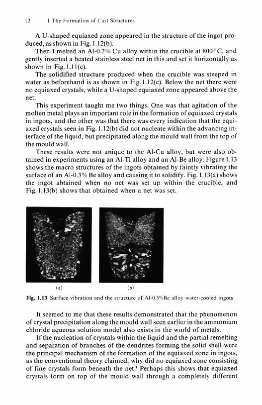
These results were not unique to the Al-eu alloy, but were also obtained in experiments using an AI-Ti alloy and an AI-Be alloy. Figure 1.13 shows the macro structures of the ingots obtained by faintly vibrating the surface of an AI-O.3 % Be alloy and causing it to solidify. Fig. 1.13(a) shows the ingot abtained when no net was set up within the crucible, and Fig. 1.13(b) shows that obtained when a net was set.
(a) (b)
Fig. 1.13 Surface vibration and the structure of Al-O.3%8e alloy water-cooled ingots
It seemed to me that these results demonstrated that the phenomenon of crystal precipitation along the mould wall seen earlier in the ammonium chloride aqueous solution model also exists in the world of metals.
If the nucleation of crystals within the liquid and the partial remelting and separation of branches of the dendrites forming the solid shell were the principal mechanism of the formation of the equiaxed zone in ingots, as the conventional theory claimed, why did no equiaxed zone consisting of fine crystals form beneath the net? Perhaps this shows that equiaxed crystals form on top of the mould wall through a completely different

1.2 Separation Theory 13
mechanism from that propounded in the conventional theory. Somehow or other I wanted to throw light on the origin and mechanism of their formation. I thought that perhaps the key to clarifying the solidification mechanism of ingots might be hidden here.
1.2.4 In-situ Observations of the Solidification Phenomenon
I decided to try and observe with my own eyes how such crystals are formed. However, it is not easy to observe the phenomenon of the solidification of opaque metals.
At least I wanted to observe the solidification of the surface of molten metal. But nothing can be seen unless the formation of the oxide film on the surface is prevented. I wanted a hot stage microscope equipped with a vacuum so that the surface of the molten metal would not oxidize, but at that time this too was not available to me.
Then I recalled a film I had seen at the Conference on the Solidification of Metals in Brighton in 1967 produced by Dr. M. E. Glicksman and his colleague4 on the growth process of dendrites in an undercooled Sn alloy.
This was an attempt to observe the growth process of dendrites in the surface of molten metal, and in particular how the configuration of the tip of the dendrites changes depending on the growth rate. The method used was to place the fused flux of a transparent chloride on the surface of a molten Sn alloy within a glass container, and to make observations through this.
The night I saw the film I buttonholed Dr. Glicksman in the hotel corridor and questioned him about his experimental methods and failures. What he told me then was subsequently of great benefit in my research.
I began by tracing Dr. Glicksman's experiment. But the flux did not work well, and I was unable to observe the molten surface of the Sn alloy.
I thought that at least it would be possible to observe the solidification phenomenon on the molten surface if I removed the oxide film and prevented the surface from oxidizing again. Then I recalled the filtration process carried out by Dr. T. Jubb, a friend from my days at the University of Toronto.
He had joked that "When I show this process to Japanese, they soon imitate it". In this method Sn was melted within a glass tube with a narrowed tip, and made to trickle down in a vacuum. This method gave me an idea, and I made the glass filter shown in Fig. 1.14 so that Dr. Jubb would not accuse me of imitating his method.
It is not that I did anything special in particular. I merely sealed one end of a glass tube by heating and inserted an iron nail while it was still hot and opened up a hole. I contrived it so that when the molten metal flowed down from the hole the oxide film would be stripped off. This was a true skinning device.

14 1 The Formation of Cast Structures
1\ I~! (b) Fig. 1.14 Filters. (a) Dr. Jubb's filter; (b) My filter
net
Sample
Fig. 1.15 Filter equipment
As shown in Fig. 1.155, I placed two filters, one on top of the other, and put them in a tubular pyrex glass container. I then placed an Sn alloy sample in the top filter. On top of this I placed a glass container which had a copper net in it, and while heating the whole I evacuated it and sealed the top part. I used a gas burner to heat the copper net from outside the container, and removed the residual oxygen, and then melted the sample inside the filter and made it flow downward, stripping off the oxide film on its surface.
I repeated the same operation with the lower filter, and collected in the bottom of the container a metal sample with no oxide film and a clean surface.
I selected an Sn-Bi alloy as the sample for the simple reason that this alloy has a low melting point. But it was extremely fortunate that I chose this alloy first of all, as the specific gravity of its primary crystals is smaller than that of the molten metal.

I j.>'icroscope
8 Sample
Air 8~i···"· I -ni- ~ .;X=---: a:: lu.'.ri:" ..... I ""'-.......7 , \ Oxide
Heater Furnace
Fig. 1.16 In-situ observation equipment
1.2 Separation Theory 15
>
Finally I inserted the pyrex container at the bottom of which the Sn alloy sample had collected in a horizontal tubular electric furnace made by hollowing out a chamotte brick, as shown in Fig. 1.16. After melting the sample, I blew a cold blast onto it from a small hairdryer set in one end of the container, and while carrying out unidirectional cooling I observed the solidification phenomenon that occurred on the surface of the molten metal.
In order to observe this solidification I obtained a well-worn oldfashioned microscope and attached to it an object lens with a long focal distance. I also borrowed a 16 mm movie camera.
What happened? Taking the case of pure Sn first, as shown in Fig. 1.17(a) solidification proceeded maintaining a smooth advancing interface from the cooled end, as if a curtain was being pulled across a window. As the degree of impurity increased - i.e. as the amount of Bi increased - the advancing interface of the metal was disturbed and finally the forming of dendrites was visible, as in Fig. 1.17(b).
b)
Fig. 1.17 Solidification phenomenon

16 I The Formation of Cast Structures
There was nothing at all strange about how this solidification occurred, and it was in accordance with what I had anticipated. But when the amount of Bi was further increased, I observed a solidification phenomenon differing from that so far and completely unexpected. A countlessnumber of crystals moved at a terrific speed from the cooled end to the opposite end.
It was just as if bullets had been shot out from a machine gun. Why should this phenomenon occur? Off I set for the United States in 1969. I met with Dr. Glicksman and his coresearcher, Dr. Schaefer, and asked them why this happened. It seemed that they too had no idea of the cause.
Once I arrived back in Japan I said to Motegi, my coresearcher, "Let's somehow find the cause behind this phenomenon. We will have to observe the cooled end and clarify how crystals come from there."
Observing the solidification of the cooled end was no easy matter. But Motegi is a serious-minded, ingenious and patient man, and he made a marvellous job of this difficult task.
As shown in Fig. I. I 8, the crystals that had nucleated on the cooled end of the container wall grew in a necked, top-heavy shape and eventually separated. I could see that after separation the next crystals immediately nucleated and grew and separated in the same manner. This formation and separation of crystals occurred continuously, and finally as the temperature fell a stable solid shell consisting of dendrites formed on the mould wall. The manner in which these crystals formed and separated was identical to the manner in wich water boils in a beaker.
Fig. 1.18 Formation and separation of equiaxed crystals on mould wall

1.2 Separation Theory 17
")g 6---=- - - -- <> - - -_____ =-'\. 0 __ _ -----~ ----=-==-----==--__=_ _==____ 0 ~ -=
% -==--==----_=__ -= ~ -==- I) - -=---= - -------0-- -~~ Fig. 1.19 Separation and migration of crystals
Firstly equiaxed crystals formed and separated from the mould wall, and then a columnar zone was formed.
This was a complete surprise to me. Most likely not a single person in the world had ever observed this phenomenon before.
I felt that a new dawn had arrived for research into solidification. This film is used as teaching material in several American and Euro
pean universities. Some time ago I also had a request for a copy from the University of Melbourne in Australia.
Why do the crystals jump? Apparently this seems very strange to everyone who sees the film.
Figure 1.19(a) is drawn on the basis of this phenomenon and is a conjecture at how the solidification phenomenon occurs.
It is also necessary to test what will happen when the crystals are heavier than the molten metal.
I observed the solidification phenomenon in a Bi-5 % Sn alloy instead of an Sn-Bi alloy. As can be seen in Fig.1.l9(b), the crystals bubbled up to the surface right out at the front of the cooled end and then migrated along the surface of the molten metal in the direction of the cooled end.
I carried out these observations not only for an Sn-Bi alloy, but also for Sn-Pb and Sn-Sb alloys, and exactly the same phenomenon was seen.
1.2.5 Formation of the Equiaxed Zone
These observations revealed that firstly equiaxed crystals separate from the mould wall, and then later on a stable solid shell is formed - i.e. a columnar zone is formed.
Based on these observations, I explained the solidification process in ingots as shown in Fig. 1.20. This is in the most difficult-to-explain case of an ingot with an equiaxed chill layer on the outside, then a columnar zone and another equiaxed zone in the center. My explanation is that "Firstly crystals separate from the mould wall as the result of the movement of the molten metal during the pouring and the convection along the mould wall, and then they precipitate along the mould wall. Some crystals are captured by the cold mould wall and form an equiaxed chill zone on the outer layer. The remainder float up within the molten metal. When the convection eventually weakens, the crystal separation ceases and a stable solid shell forms and columnar crystals begin to grow. The crystals that had been

18 1 The Formation of Cast Structures
(a) (b) (e)
Fig. 1.20 Process of formation of cast structure
floating in the liquid grow and precipitate, and finally form an equiaxed zone."
If equiaxed crystals did not precipitate on the growth front of the crystals, the crystals would merely grow into long columnar crystals. If sufficient free crystals to completely prevent the growth of the columnar crystals did not exist on the front, free crystals would probably be captured within the columnar zone, as shown in Fig. 1.21, and when the crystals captured in front of the columnar crystals grew without obstruction, they would form branch-like columnar crystals.
When viewed in this light, various phenomena seen in cast metals can be logically explained, as I will discuss afterwards.
In a later section I will take up the questions of why the root of the crysta I s is contracted and where the equiaxed crystals form.
1.2.6 Separation Theory and Free Chill Crystal Theory
I would like the reader to understand readily the mechanism that I have propounded as the main cause of the creation of the equiaxed zone.
Mould H-H-f--H-++-1-+-0 Molten metal
Brandt-like columnar crystats
Columnar crystals rr~-r~~~~~~~L
Fig. 1.21 Capturing of separated crystals within the columnar zone, and branch-like columnar crystals

1.2 Separation Theory 19
Nevertheless, apparently quite a large number of people still regard this as being identical to the free chill crystal theory (free crystal theory, big bang theory). It seems that this belief is particularly common among people who have enthusiastically carried out research into solidification.
For instance, in "Tekko no gyoko" (The Solidification of Steel) published by the Joint Society on Iron and Steel Basic Research of The Iron and Steel Institute of Japan in 1978 Dr. Akira Suzuki6 states that "Ohno has suggested that crystals that have nucleated heterorgeneously on the mould wall separate from the mould wall and become equiaxed crystals, but this is heterogeneous nucleation on top of the mould wall substrate, and should be included in the free crystal theory."
I frequently come up against the same opinion in discussions. When it is put down in plain writing as Dr. Suzuki did, I am able to counter this argument, but I am at a loss to refute what is not written down.
Accordingly it seems that I must explain what the free chill crystal theory is about.
This theory was proposed by Genders7 in 1926, and runs to the effect that "Molten metal poured into a mould is deprived of its heat by the mould, and a large undercooled zone is formed near the mould wall and free crystals are created through "copious nucleation" within this undercooled zone, as in Fig. 1.22, and these free crystals migrate within the molten metal and precipitate". This theory is also referred to as the big bang theory.
Undercoold zone Fig. 1.22 Free chill crystal theory
People who regard our "separation theory" as being the same as the free chill crystal theory invariably say that "By chance no effective nucleant existed in the molten metal you used. If an effective nucleant did exist, free crystals would surely have nucleated within the liquid."
The world-renowned scholar of metal solidification, Dr. B. Chalmers, discusses the formation of free crystals in detail in his book "Principles of Solidification "8.
According to him, the number of crystals formed within the undercooled zone in contact with the mould wall increases the greater is the

20 I The Formation of Cast Structures
number of nucleants existing in the undercooled zone and the greater is the extent to which the liquid is undercooled.
One of Dr. Chalmers' students was a certain Dr. Rutter who teaches solidification at the University of Toronto where I studied. He and his colleagues undercooled an Ni-Cu alloy and investigates the relationship between the degree of undercooling and the solidification structure. The results9 obtained are shown in Fig. 1.23.
Degree at undercooling
Fig. 1.23 Influence of the degree of undercooling on the size of crystals
These were extremely interesting results. When undercooled below a temperature of approximately 80 0 C, the structure consisted of fine equiaxed crystals, but at a greater degree of undercooling the crystals rapidly increased in size, then when the degree of undercooling was increased to an extreme extent, the structure again became fine.
It has become clear that this phenomenon exists in other alloys also. Since in actual casting the undercooling temperature is extremely low
at about I 0 C, such a large degree of undercooling is quite impossible unless special methods are devised, but at all events the fact that when the degree of undercooling increases in this manner the crystals suddenly become coarse at a certain point cannot be explained by the free chill crystal theory. In order to solve the riddle of why the crystal size suddenly increases at one point as the degree of undercooling increases, I decided to observe again the solidification phenomenon in Sn-Bi alloysIO.
I built some apparatus for in-situ observations of the solidification phenomenon, as shown in Fig. 1.24. This was similar to the equipment used earlier to observe the formation and separation of equiaxed crystals, but I set an alumel-chromel thermo-couple in the base of the container so as to enable measurement of the sample temperature. I also opened up the top surface so as to provide a view of the whole procedure.
Sample Hea t ing element Oxide
~::5: ... Cold air
furnace
Fig. 1.24 Equipment for observing the solidification of undercooled metals

1.2 Separation Theory 21
Using this equipment, I melted Sn-Bi alloys with various degrees of concentration and then carried out repeated fusion and solidification. As Fig. 1.25 shows, the degree of under cooling rose as the number of times the process of fusion and solidification was repeated increased.
Time
2
~o
Degree of undercooting 3
Solidification temperature
Fig. 1.25 Repetition of melting and solidification, and the degree of undercooling
Fig. 1.26 Degree of undercooling and the solidification phenomenon
What I observed here was the trend shown in Fig. 1.26. When the degree of undercooling is small, the crystals separated from the cooled end, whereas once the degree of undercooling reached a certain magnitude the crystals formed a stable solid shell at the cooled end and grew without obstruction.
The degree of undercooling at which this increase in size occurs is 6 ° C for Sn-3% Bi and 12°C for Sn-5% Bi, so that as the Bi amount increased the degree of under cooling required for the increase in size also increased.
When the degree of undercooling was raised extremely, the neckedshape branches of the dendrites that had once grown rapidly broke off owing to recalescence, resulting in an extremely fine structure.
This structural transition differed depending on the amount of Bi, and showed the tendency depicted in Fig. 1.27.
When I visited the University of Toronto in 1978, I related this to Dr. Rutter. He said "We observed no such structural changes with pure Ni." Since with pure Ni there is no solute that curbs the growth of the root of the crystals and promotes their separation, naturally there are no major structural changes depending on the degree of undercooling, and a stable solid shell soon forms and columnar crystals grow.
Figure 1.28 is an ingot cross section that has frequently appeared in books on casting for a long time. I too thought it natural that quenching

22 1 The Formation of Cast Structures
30'-~~--.\r---'------'----'
\ F ine grains 25
\ .... "<1 20 .~
\ o o e ~ 15
Columnar dendrites ~
..,-// c :>
'0
~ 10 7 -----_.-" --Coi;;;;;nar crystal "" .,
o Equiaxed c~sta ls/
5 / Equiaxed crysta ls
o ,/' o 3
Bi (% )
Fig. 1.27 Effect of the degree of undercooting and the amount of Bi on the solidified structure of Sn-Bi alloys
Fig. 1.28 Ingot macro structure
produces an equiaxed chill crystal zone on the outermost layer. One day, however, one of my students, Shigeki Y oshie, said" Looking at the macro structure of Al ingots, it seems that there are cases in which an equiaxed chill layer exists on the outermost layer and cases in which it does not."
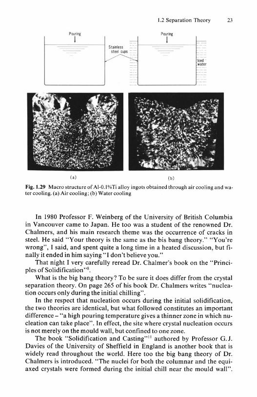
I immediately decided that he should write his graduation thesis on this theme. My wife is a dentist, so we have many stainless steel cups at home. When I commenced this research my laboratory had no money, so I brought these cups along and applied India ink to their inside, and then poured an Al-O.I % Ti alloy into them.
This produced the fine structure shown in Fig. 1.29(a). In order to undercool the liquid even further, I cooled the cups in ad
vance in iced water, and when I poured the alloy into these as before, what happened was not that nucleation was promoted and the crystals became finer, but that the outside of the casting consisted of columnar crystals and the equiaxed crystals on the inside also became coarse, as shown in Fig. 1.29(b).
The fact that the quenched casting was coarser brilliantly refuted the free chill crystal theory.
Pouring
I
( a )
1.2 Separation Theory 23
Pouring
=-1------==='::::::::::::==- J=-Stainless I r- -steel cups --
~
(b )
-Iced -water
I=-
Fig. 1.29 Macro structure of Al-O. l%Ti alloy ingots obtained through air cooling and water cooling. (a) Air cooling; (b) Water cooling
In 1980 Professor F. Weinberg of the University of British Columbia in Vancouver came to Japan. He too was a student of the renowned Dr. Chalmers, and his main research theme was the occurrence of cracks in steel. He said "Your theory is the same as the bis bang theory." "You're wrong", I said, and spent quite a long time in a heated discussion, but finally it ended in him saying "I don't believe you."
That night I very carefully reread Dr. Chalmer's book on the "Principles of Solidification"s.
What is the big bang theory? To be sure it does differ from the crystal separation theory. On page 265 of his book Dr. Chalmers writes "nucleation occurs only during the initial chilling".
In the respect that nucleation occurs during the initial solidification, the two theories are identical, but what followed constitutes an important difference - "a high pouring temperature gives a thinner zone in which nucleation can take place". In effect, the site where crystal nucleation occurs is not merely on the mould wall, but confined to one zone.
The book "Solidification and Casting"lt authored by Professor G. J. Davies of the University of Sheffield in England is another book that is widely read throughout the world. Here too the big bang theory of Dr. Chalmers is introduced. "The nuclei for both the columnar and the equiaxed crystals were formed during the initial chill near the mould wall".

24 I The Formation of Cast Structures
This is based on the fact that the nucleation of crystals occurs within the liquid in the undercooled zone near the mould wall, as shown in Fig. 1.22.
It is impossible with this explanation to explain the fact that, as described earlier, the crystals do not become finer as the degree of undercooling increases, but conversely become coarse at one stage.
1.2.7 Origin of Showering Crystals Caused by Cooling of the Molten Metal Surface
I have had opportunities to give lectures at many universities, including the Massachusetts Institute of Technology in the United States and the University of Cambridge in England, as well as many other universities in America, Britain, Canada, Germany, France, Switzerland, Australia, China, South Korea and Brazil. Wherever it has been screened, our film showing the process by which equiaxed crystals are formed has caused a great stir.
When I visited the University of Oxford in 1975 I was interested to hear what Dr. J. D. Hunt, a recipient of the AI ME's Mathewson Gold Medal, would say about his explanation 12 that the equiaxed zone is formed as the result of the partial remelting and separation of dendrites, and sure enough we ended up in a very heated argument. He insisted furiously that "Perhaps what you describe may occur also. But the formation of equiaxed crystals occurs as the result of the partial remelting of dendrites. As you can see in Fig. 1.30, we have seen with our own eyes that crystals precipitate in an ammonium chloride model."
Fig. 1.30 Crystal precipitation in an ammonium chloride aqueous solution model
Not in the slightest flustered, I replied "Sufficient care must be taken when observing ammonium chloride models. There is a risk that they may provide incorrect information. No doubt the precipitation phenomenon that you observed was in actual fact the crystals that had separated from the wall of the container in the stage prior to the formation of a solid shell floating finely within the molten liquid, and finally growing large enough to be visible to the naked eye and then precipitating. Or perhaps they were

1.2 Separation Theory 25
formed as the result of the rupture of the outside of the solid shell on the surface when the surface dropped as the result of the evaporation of the ammonium chloride aqueous solution. We must constantly keep in mind the existence of the transparent glass plate of the side walls of the container."
When I later gave a lecture at the University of Sheffield a young man made exactly the same claim as Dr. Hunt. He was Dr. M. H. Burden, a student of Dr. Hunt. Apparently he made a special trip to the University of Sheffield just because of my visit. He was extremely persistent, so I merely said "Alright then, next time I come I will show you convincing evidence."
I am about to show you some frames from a film made for this purpose. Since in the past I had observed the same phenomenon that they had seen in an ammonium chloride model, I can well understand the opposition of Dr. Hunt and Dr. Burden.
Probably some of my readers have performed a similar experiment to that of Dr. Hunt, and perhaps some may do so in the future. Such people are sure to interpret the results in the same manner as Dr. Hunt. So let me introduce our experiment l 3, which was carried out with utmost care.
I I
(a ) (b )
Fig. 1.31 Equipment for observing solidification in an ammonium chloride aqueous solution model. (a) Acrylic resin double container; (b) Stainless steel watercooled tube
As shown in Fig. 1.31, I used hot water to heat the side walls of a transparent container made of acrylic resin, and completely prevented the nucleaton of crystals on the side walls of the container and ensured that heat escaped from the surface alone.
The crystals that nucleated on the surface had a specific gravity of 1.5, and this was considerably heavier than that of the mother liquor, which was about 1.1, but the crystals did not precipitate at all. Instead they spread out while forming a thin solid shell along the surface, as shown in Fig. 1.32.
Even when viewed from the side of the container, no such showering of crystals from the surface as propounded14 by Dr. R. T. Southin.of Australia was observed. Neither did a precipitation of crystals caused by a par-

26 I The Formation of Cast Structures
(a) ( b) ( e)
Fig.1.32 Solidification phenomenon on the surface of an ammonium chloride aqueous solution model
tial remelting and separation of the branches of dendrites in the solid shell on the surface occur, as claimed by Dr. Hunt.
The crystals formed on the surface did not precipitate, but repeatedly turned white and then grey and spread out along the surface.
Perhaps even some of the solidification researchers who have used an ammonium chloride model have not seen such a phenomenon, because when I show this film they ask me "Why? Why don't the heavy crystals sink?"
No doubt readers will also find it strange that heavy crystals do not sink. But in actual fact that is the case.
This even occurs with metals. When Al was melted in a heated crucible and a chill block of iron was placed on the surface of the molten metal and it was cooled, in the case of impure Al equiaxed crystals occurred that had clearly precipitated in the bottom of the crucible as in Fig. l.33(a), but in the case of pure AI, no precipitated crystals were seen, as shown in Fig. l.33(b)lS. This shows that even if the surface of the molten metal is cooled, the crystals precipitate in some cases but not in others.
The reason is simple. It is because the gas film formed on the advancing interface provides
the crystals formed on the surface with buoyancy, as shown in Fig. 1.34(a). If the gas escapes as in Fig. 1.34(b), the crystals can precipitate, but when it cannot escape the crystals are unable to precipitate, and they grow along the surface.
In the earlier case of the ammonium chloride model, gas escaped from the advancing interface of the liquid, and the crystals leaked and grew in the mother liquor as the gas dispersed, and again a gas film formed and became whitish. Repeating this phenomenon over and over again, the crystals eventually covered the whole surface, pulsating as they did so.
It was also observed later on that the formation and disappearanc of this gas film was repeated and that the periphery of the solid shell in contact with the container walls ruptured as the result of the pulsating of the

(a)
~ , Chi ll b lock
1.2 Separation Theory 27
rucible
Fig. 1.33 Surface cooling of molten AI, and the resulting ingot structures. (a) AI-O.05% Ti; (b) 99.99%AI
surface solid shell at that time, and that some of the ruptured crystals precipitated. The pulsation of the solid shell on the surface even caused ruptures along the grain boundaries of the crystals.
Viewed from the side, it looked just as if new crystals were formed from the tip of the dendrites of the surface solid shell.
Closer inspection of such crystal grains, however, revealed that the crystal grains formed through the partial rupture of the solid shell as the result of the pulsation of the surface solid shell were ones that were floating within the mother liquor, and that they changed in size and moved around within the mother liquor. When the liquid temperature finally falls these separated crystals grow and become visible to the naked eye. It is mistakenly interpreted that these crystals were formed at that site or were formed by the branches of nearby dendrites breaking off.
Plate-like crystals Granular crystals
~~~/.~~ / ~--==-~ - - --. ---~=-~Gas film_
Mother liquor. __ -= Mother liquor
( a) (b )
Fig. 1.34 Gas on the advancing interface, and the solidification phenomenon

28 I The Formation of Cast Structures
I used a microscope to view sideways the dendrites growing downwards from the surface. I learnt that the crystals floating in the liquid grew there and became visible and precipitated quite unrelated to the branches of the growing crystals.
In order to experiment with an ammonium chloride model, I believe that the following method provides more correct information.
Using the same acryclic resin container as in Fig. 1.31, I poured hot water into the outer chamber and the heated ammonium chloride aqueous solution model into the inner chamber. Inside this I inserted a stainless steel cooling tube heated beforehand to 100 0 C. Finally I ran water through this cooling tube.
Firstly fine crystals of ammonium chloride appeared sporadically on the surface of the cooling tube, as in Fig. 1.35(a), and finally they broke away in pieces from the side walls, and the crystals precipitating along the surface of the cooling tube knocked down the crystals that had crystallized downwards. After this chain reaction-like formation and separation of crystals, finally a stable solid shell formed on the surface of the cooling tube, as shown in Fig.1.35(b).
A stable solid shell did not readily form in the lower part of the cooling tube, but once it did form no subsequent formation of new equiaxed crystals was observed.
When the temperature of the water supplied to the cooling tube is low, a stable solid shell forms quickly, and conversely when it is high the crystals continue to form and separate indefinitely, and a stable solid shell does not form easily.
Since this model is exactly identical to the phenomenon in the film whereby an Sn alloy solidifies on the container wall, it is very suggestive of the solidification phenomenon on the mould wall of ingots.
(a) (b)
Fig. 1.35 Solidification phenomenon on the surface of the cooling tube in an ammonium chloride model

1.2 Separation Theory 29
1.2.8 Confirmation of the Separation Theory
There is one more comment that I would like to add finally with regard to the formation of equiaxed crystals.
I feel that even if the reader can vaguely understand my explanation so far that the equiaxed crystals in the center of ingots are formed first and then later on the outer columnar crystals surrounding them are formed, probably he still feels a tinge of uneasiness, as if he were being deceived. It may seem that I am being long-winded, but let me bring home this point and conclude my discussion of the mechanism by which equiaxed crystals are formed.
Taking numerous eutectic system alloys, 116 poured into simple cylindrical metallic moulds hypo-eutectic and hyper-eutectic alloys whose composition closely resembles the eutectic composition shown in Fig. 1.36.
Fig. 1.36 Distribution of primary crystals in eutectic system alloys. (a) Non-leading phase primary crystals; (b) Leading phase primary crystals
The reason I selected a composition closely resembling the eutectic was that when studying the behavior of primary crystals during solidification, unless the amount of primary crystals is small one ends up not knowing at what one is looking.
I discovered the following common phenomenon in the macro structure of the ingots produced. Be they hypo-eutectic or hyper-eutectic, Al-Zn, Al-Cu odr Pb-Sn, there was a tendency for the primary crystals that should crystallize first to always gather in the center, as shown in Fig. 1.36.
Naturally, when the difference between the specific gravity of the primary crystals and the molten metal is great, the primary crystals segre-

30 I The Formation of Cast Structures
gate upwards or downwards. In any case, however, the primary crystals that should crystallize first according to the equilibrium phase diagram were located in the center of the ingot, and were surrounded by the eutectics that should form later after reaching eutectic temperature.
I have cited the results of this experiment on the solidification of eutectic system alloys at the end of the description of the mechanism by which equiaxed crystals are formed because in order to develop technology to control cast solidification structures I feel convinced that first it is necessary to rid ourselves of the old concept - may I call it a superstition - that the equiaxed crystals in the center region of ingots are formed after the outer columnar zone has been formed.
1.3 Origin of the Formation of Equiaxed Crystals
So far I have discussed how the equiaxed zone that is surrounded by the columnar zone is formed.
Now I would like to go into the question of the origin of these equiaxed crystals.
When molten metal is poured into a mould, heat is lost through the mould wall. Consequently, solidification commences preferentially on the mould wall.
When the crystals formed on the mould wall come in contact with adjacent crystals and form a solid shell, equiaxed crystals cannot form, and a casting consisting solely of columnar crystals is produced.
I have advocated the "crystal separation theory" that asserts that in the stage prior to the formation of this stable solid shell, equiaxed crystals are formed by crystals forming and separating from the mould wall, as shown in Fig.1.37(a).
Mould 1 ( Molten metat
I Separated crystal
Coverong mate"al
~~ Z) Molten metal
.... COId charge t " Molten metal
- 0 Separated - crystal
Molten metal
o O"'"Separated crystal Separated
- 0 crystal
0 (d) (a) (b) (e)
Mould l' ''''':':::::. ""'" Separated crystal
. Gale - '--__ ---'
Mould 0
I 0
Molten • metal
Separated crystal
Solrd shell
(e) (f) (g)
Fig. 1.37 Formation and origin of equiaxed crystals

1.3 Origin of the Formation of Equiaxed Crystals 31
I have realized that when my theory is explained in this manner it is easy for listeners to gain the impression that equiaxed crystals can be formed only on the mould wall.
What I am saying refers to the ordinary solidification of ingots and castings in which molten metal is merely poured into a mould and solidified. If sites other than the mould wall are provided for the molten metal to cool, naturally the formation of crystals there also must be considered.
For instance, if a cold covering material is placed on the surface of the molten metal in the mould, crystals would form on the lower surface of the covering, as shown in Fig.1.37(b). The crystals would grow along the lower surface of the covering material. Unless there is something to restrain their growth along the lower surface of the covering material, a stable solid shell will form there, so crystals cannot be expected to separate and precipitate.
If something prevents the growth of the crystals, they will be unable to form a solid shell, and will become granular and precipitate. Later on I will discuss why they become granular.
When a cold charge is projected into molten metal, as in Fig.1.37(c), the surface of this cold charge also causes the formation of equiaxed crystals. As shown in Fig. 1.37( d), when the protecting tube of a thermo-couple or a bar is projected into molten metals close to solidifying point, the same phenomenon would also occur on their surfaces.
Strictly speaking, however, the first consideration is the fact that the crystals nucleated on these surfaces have been prevented from forming a stable solid shell, and that crystals in a form susceptible to separation are created.
However, the question of whether or not the crystals that have formed and separated there will actually survive until the end and form an equiaxed zone depends on the cooling capacity of the cold charge and the temperature of the molten metal. Even if equiaxed crystals are formed and separate, they will melt again and disappear if the temperature of the molten metal is too high.
In the continuous casting of ingots poured using an immersed nozzle, the upper surface that is cooled by the air from the immersed nozzle is also thought to be a cause of the formation of equiaxed crystals, as shown in Fig.1.37(e).
In castings with a complex configuration, the formation and separation of crystals could also occur on the inner walls of the gate or sprue runner, as in Figs. l.37(f) and l.37(g).
When the pouring temperature is high, the crystals formed at the gate and sprue runner melt again, and the formation of equiaxed crystals would occur mainly on the wall of the mould itself.
Many people insist that "free crystals nucleate not only on the mould wall, but also within the molten metal away from the wall", but as I will discuss later, this occurs when special measures are taken. The mould wall

32 I The Formation of Cast Structures
is the main source of their formation when molten metal is simply poured into a mould and solidified.
It is also easier for them to occur towards the upper part of the mould wall - i.e. close to the surface of the molten metal. This is because during the pouring this part is always in the initial stage of solidification. The solid shell is in its most instable stage. It is the easiest for the molten metal to move here.
Thus when I say that "It is easy for equiaxed crystals to form and separate there", apparently I give the impression of saving that "Equiaxed crystals form only at this place". This makes me realize keenly the difficulty of explanation.
Using a mould with heated side walls, Professor S. Engler and a colleague1? at Aahen Technical University in Germany blew gas onto the surface of the molten metal in the mould. Based on the results of this experiment they reported that "Contrary to Ohno's claim, not only the mould wall or the places where the molten metal, mould wall and air meet, but the whole free surface of the molten metal also causes the formation of equiaxed crystals."
What is important is the fact that, as I related earlier in the section dealing with the origin of the formation of equiaxed crystals, I am not asserting that "There is absolutely no way in which crystals can separate from the solid shell of the surface". What I am saying is that "The place where crystals form and separate most easily is near the corners of the surface and mould wall". Let me now introduce an experiment13 I performed in response to the paper by Professor Engler.
Fig. 1.38 Surface cooling by gas blowing
Using equipment such as that shown in Fig. 1.38, I melted 99.99 % Al in a graphite crucible and lowered the furnace temperature to 720 0 C. I then blew air on the center of the surface at a pressure of 0.4 kg/ cm2, and this produced a structure consisting solely of columnar crystals growing downwards from the surface of the molten metal, as shown in Fig. 1.39(a).
When this same air-blowing was carried out with the crucible removed from the furnace, as in Fig.1.38(b), two zones appeared as shown in

1.3 Origin of the Formation of Equiaxed Crystals 33
(a) (b)
Fig. 1.39 Macro structure of 99.99%Al in which air is blown onto the surface at a pressure of0.4kg/cm2 inside the furnace (a) and outside the furnace (b)
Fig. 1.40 Macro structure of 99.8%Al ingots obtained through surface cooling. Wind pressure: (a) (b) Gass pressure 0.4 kg/cm2; (a) (c) Cooling inside furnace; (c) (d) Gas pressure 0.6 kg/cm2; (b) (d) Cooling outside furnace

34 I The Formation of Cast Structures
Fig.1.39(b) - a columnar zone growing downwards from the surface and a zone in which crystals grew from the side walls of the crucible. In neither case did equiaxed crystals appear.
When less pure 99.8 % Al was used in the same experiment, only columnar crystals growing downwards form the surface appeared when air was blown into the furnace, as shown in Fig. 1.40(a), but when this blowing was carried out outside the furnace, aU-shaped equiaxed zone appeared as shown in Fig. 1.40(b), suggesting that the crystals precipitated along the mould wall. When the pressure of the air blown was increased to 0.6 kg/ cm2, a conical equiaxed zone appeared, as shown in Fig. 1.40(c), demonstrating clearly that the solid shell on the surface had been ruptured mechanically and that crystal showering had occurred. When this was conducted outside of the furnace, equiaxed crystals existed over the whole area, as shown in Fig. 1.40( d).
These results indicate the importance of the mould wall, and particularly its upper part, as a cause of the formation of equiaxed crystals, as long as heat escapes preferentially from the side walls of the mould.
No doubt it would not be impossible to deliberately produce free crystals within the molten metal away from the mould wall. One method would be to alter the liquid composition in one part of the liquid and add an additionagent that would raise the primary crystal crystallization temperature at that site. Adding to the molten metal an additive that requires a large heat of vaporization and heat of fusion and carrying out internal cooling would also be effective. However, in order to control cast structures I believe that it is important to first have a proper grasp of where equiaxed crystals come from in cases when the molten metal is merely poured into a mould, not in cases when such special measures are devised.
1.4 Formation and Separation of Equiaxed Crystals
I have stated that equiaxed crystals form easily on the mould wall. Let us consider the question of just how equiaxed crystals do form on the mould wall.
Strangely enough, articles discussing the growth of crystals on the mould wall are not readily available. This is a complete surprise.
Whereas many articles deal with the growing tips of the branches of dendrites, the mechanism of cellular growth, or the configuration and behavior of the advancing interface in the growth process of crystals that have already formed, for some reason I could find no articles explaining how a solid shell is formed immediately after the nucleation on the mould wall, or how crystals separate.
Probably this was because the instantaneous formation of the stable solid shell on the mould wall meant that nobody imagined that the crystals separate prior to this.

1.4 Formation and Separation of Equiaxed Crystals 35
1.4.1 Growth of Crystals on the Mould Wall
In order to understand why necked-shape, top-heavy crystals are formed on the mould wall, I believe it is necessary to know the growth behavior of crystals along the mould wall.
When a molten pure metal is poured into a mould, an undercooled zone is formed in the liquid along the mould wall.
Since the undercooled zone is largest at the mould wall, as shown in Fig. 1.41 (a), the crystals that have nucleated on the mould wall grow without any restraint along the mould wall first of all, as in Fig. 1.41 (b), and come in contact with the adjacent crystals and form a solid shell, and then grow in a columnar shape within the residual liquid.
~ ::J
~ ~ .,..h una.,eoo, E ., I-
Mould wall Distance
<a)
Fig. 1.41 Formation of solid shell on mould wall
Fig. 1.42 Dendrites on the solid shell
S tabl e sol id shell
" /--=-====
Mould
(b)
The process by which crystals first grow along the mould wall is of vital importance to an understanding of the formation of equiaxed crystals, but this process seems to have been unexpectedly ignored in the past, so let me introduce here a simple experiment I performed.

36 I The Formation of Cast Structures
(a)
(b)
Fig. 1.43 AI crystals in the initial stage of formation of the solid shell. (a) from directly above;
(c) (b) slantwise from above; (c) from the side
I removed from the furnace a graphite crucible in which 99.99% Al had been melted, and carried out decantation at various stages immediately after solidification had commenced, and then removed the residual liquid and took out only the solid shell.
In Fig. 1.42 the solid shell has been cut in half vertically. You can see how large dendrites grow along the mould wall.
In Fig. 1.43 the crystals at the bottom of this solid shell have been cut out. For better viewing I have taken photographs from three directions.

1.4 Formation and Separation of Equiaxed Crystals 37
=--=-~ ~ - oiiiie segregation-::-----=-~=:-.=--=-= Molten metal- - - - - - - - - - - -
--Trunk- -- -- ---_ --=-_---= ==Primary branch=
Fig. 1.44 Growth of dendrite branches on the mould wall in initial stage of solidification
Figure 1.43(a) is taken from directly above. You can see how the large trunks along the mould wall intersect at right angles. Primary branches grow from these trunks along the mould wall. Naturally a close inspection also reveals secondary side-branches. Let us observe this slantwise from above. Projections can be seen above the trunks, as shown in Fig. 1.43(b), and a noticeably large upwards projection can be seen at the intersecting point of the trunks along the mould wall.
Let us now take a look from the side. In Fig.1.43(c) the branches that appeared to be small projections in Fig. 1.43(b) cover the solid shell in a direction parallel to the central trunk. Look at the length of these upturned branches. You will realize that the growth of the branches on both sides of the central trunk is tardy.
I have drawn Fig. 1.44 in order to explain this. As the trunk and branches grow, segregation of the solute occurs on these surfaces - i.e. the liquid with a low melting point composition segregates - so growth is delayed more at places where such solute segregation is greater.
I think this will have demonstrated two facts. Firstly, crystals grow preferentially along the mould wall. Secondly, segregation of the solute has a major influence on crystal growth.
1.4.2 Growth of Necked-Shape Crystals
Let us move on to a discussion of necked-shape, topheavy crystals. I have just demonstrated how Al crystals have XYZ trunks that intersect each other at right angles. Most metals possess such principal axes of crystals.
It is known that in general the orientation of the crystals that grow preferentially differs depending on their structure, as shown in Table 1.1.
Table 1.1. Preferential growth direction of crystals
Metal
Fe, Si, ~-Brass AI, Cu, Ag, Au, Pb Cd,Zn ~-Sn
Structure
Body-centred cubic lattice Face-centred cubic lattice Hexagonal close-packed Tetragonal
Preferred orientation
(100) (100) (IOTO) (110)

38 I The Formation of Cast Structures
The Al case cited here has a face-center cubic lattice crystal structure, and is known to grow preferentially in a (100) direction.
This is because in cubic lattice metals that crystallize in an octahedral outward shape as in Fig. 1.45, during the growth the smallest place in the segregation of the solute is a pyramid point consisting of four (111) surfaces. The projections from this point form the principal axes of the dendrites. Let us consider the cases in Fig. 1.46 in which metallic crystals having three principal axes have nucleated on the mould wall.
4?J 4J + ?" ~~ ~
(a) (b) (e) (d)
Fig. 1.45 Growth process of principal dendrite trunk from an octahedral crystal
Fig. 1.46 Mould wall and the growth axes of cubic system metals
Broadly classified, I believe there are three cases - (a) two axes are parallel to the mould wall and one is perpendicular; (b) one axis is parallel; (c) all three axes are neither parallel nor perpendicular to the mould wall. Of these, I think that case (c) has the highest probability of occurrence.
All of these crystals nucleated on the mould wall have their growth along the mould wall restrained by segregation, but the root of the crystals is most easily constricted in case ( c) in Fig. 1.46.
1.4.3 Separation and Multiplication of Crystals
While the growth of the root of the crystals nucleated on the mould wall is being restrained by the liquid with a low melting point composition, they grow into a top-heavy shape as shown in Fig. 1.47.
When such necked-shape crystals are formed on the mould wall, their roots are instable and convection easily causes them to separate. For in-

(a l
1.4 Formation and Separation of Equiaxed Crystals 39
Fig. 1.47 Formation of granular crystals on mould wall
stance, even without great convection, when the difference between the specific gravity of the crystallized crystals and that of the molten metal is large, the small neck cannot support the big head, and even slight movement of the molten metal causes the crystals to separate from the mould wall. The separated crystals then induce nearby crystals to separate.
When the crystals that have separated from the mould wall are extremely light in comparison to the molten metal, they float up against the downwards convection along the mould wall, while when they are heavier than the molten metal they precipitate along the mould wall and induce separation of the crystals on the lower mould wall. The formation and separation of crystals progresses on the mould was in a chain reaction.
As demonstrated earlier in the ammonium chloride aqueous solution model, the separation of such crystals occurs most easily in the initial stage of solidification. This is because the convection that shakes the crystals on the mould wall is greatest immediately after pouring, when there is a large temperature difference between the mould wall and the molten metal, and becomes smaller as the temperature of the molten metal in the mould becomes uniform within and without.
When I state that the formation and separation of crystals occurs in the initial stage of solidification prior to the formation of the stable solid shell, I have been asked "Your theory is based on observation of the solidification phenomenon on the surface of an Sn alloy. Can you state positively that this also occurs in the same manner on the mould wall below the surface?".
As you know, molten metal is opaque, and even if the X-ray transmission method were used the movement of fine crystals in the metal mould would not be readily visible. I believe an examination of how heat is transferred between the molten metal and the mould wall is one method of replying to this question.
Using various mould materials with different cooling capacities, 118
built a mould whose interior dimensions were 30 x 100 x 110 mm, as shown in Fig. 1.48(a). It was 15 mm thick and the base was insulated with bricks. I set three thermo-couples about halfway up the mould as shown in the figure, and poured 99.8 % Al onto the mould wall from 680 0 C. I continually measured the temperature at these three points, and based on

40 I The Formation of Cast Structures
(a)
... Q)
:I: ~----~T~im-e------
(b)
Fig. 1.48 Mould cooling capacity and heat conduction from the molten metal to the mould
these data I obtained the coefficient of heat transfer under abnormal condition.
Tracing the temporal variation in the coefficient of heat transfer, I realized that two major types exist, as shown in I and 2 of Fig. 1.48(b).
In type 1 a solid shell formed instantaneously immediately after the pouring, and absolutely no equiaxed crystals appeared. Since solid Al conducts heat better than liquid AI, it can be seen that at the moment the stable solid shell formed the coefficient of heat transfer increased, and then smoothly decreased as gaps formed between the mould wall and the solid shell as the result of the solidification contractions. I think this curve will conform to readers' expectations.
The problem lies with type 2. This type of heat movement was observed in all ingots in which an equiaxed zone was obtained. As time passed, the coefficient of heat transfer slowly fluctuated steadily upwards. This indicates that the crystals formed and separated continuously on the mould wall and could not easily form a stable solid shell.
When crystals separate from the mould wall they move about within the liquid. In general the temperature of the molten metal in the mould immediately after pouring is lower near the mould wall than in the center. Since heat also escapes from the surface of the molten metal, strictly speakting the surface that is exposed to the air would also have a lower temperature than that within the molten metal. When such temperature differences exist from place to place within the molten metal in the mould, partial melting and growth is repeated on the surface of the crystals moving about within the molten metal.
Sometimes crystal multiplication occurs in such cases. Figure 1.49 shows the mechanism by which crystals multiply. When the separated crystals enter a high-temperature region they melt from the outside, and when they enter a low-temperature region they grow.
If the crystals have necked-shape branches, new crystals are born through the partial remelting and separation of the branches.

1.4 Formation and Separation of Equiaxed Crystals 41
Low High Low High Low temperature temperature temperature temperature temperature
0 - 0- 0 / Growth Redissolut ion Growth
- 0
Aedissolution ~ 0 c{P U-= 0 o-c{? c{? c{?
Mou Multiplication
Fig. 1.49 Multiplication of separated crystals
This crystal multiplication does not occur only as the result of heterogeneity in the temperature of the molten metal in the mould. It also occurs through heterogeneity in the concentration of the solute.
When separated crystals arrive at a place in the mould where liquid with a low melting point composition is unevenly distributed, naturally local melting must occur on their surface. Such multiplication is accelerated by the electromagnetic stirring to be discussed later, but in order for multiplication to occur, firstly it is necessary that crystals separate from the mould wall in the initial stage of solidification and exist within the liquid as free crystals.


![Graphite Structures in Cast Iron English[1]](https://img.pdfslide.net/doc/110x75/545d8292af7959be0e8b4d0b/graphite-structures-in-cast-iron-english1.jpg)