Embed Size (px)
Citation preview

Printed on 03/11/16
Solids Separation Study Guide
February 2016 Edition
Wisconsin Department of Natural ResourcesOperator Certification Program
PO Box 7921, Madison, WI 53707
http://dnr.wi.gov
Subclass B
Wisconsin Department of Natural Resources
The Wisconsin Department of Natural Resources provides equal opportunity in its employment, programs, services, and functions under an Affirmative Action Plan. If you have any questions, please write to Equal Opportunity Office, Department of Interior, Washington, D.C. 20240. This publication is available in alternative format (large print, Braille, audio tape. etc.) upon request. Please call (608) 266-0531 for more information.
Wastewater Operator Certification

Printed on 03/11/16
PrefaceThe Solids Separation Study Guide is an important resource for preparing for the certification exam and is arranged by chapters and sections. Each section consists of key knowledges with important informational concepts needed to know for the certification exam. This study guide alsoserves as a wastewater treatment plant operations primer that can be used as a reference on the subject. Any diagrams, pictures, or references included in this study guide are included for informational/educational purposes and do not constitute endorsement of any sources by the Wisconsin Department of Natural Resources.
Preparing for the exams:1. Study the material! Read every key knowledge until the concept is fully understood and known to memory.
2. Learn with others! Take classes in this type of wastewater operations to improve understanding and knowledge of the subject.
3. Learn even more! For an even greater understanding and knowledge of the subjects, read and review the references listed at the end of the study guide.
Knowledge of the study guide material will be tested using a multiple choice format. Every test question and answer comes directly from one of the key knowledges.
Choosing a test date:Before choosing a test date, consider the time needed to thoroughly study the guides and the training opportunities available. A listing of wastewater training opportunities and exam dates is available at http://dnr.wi.gov by searching for the keywords “Operator Certification”.
AcknowledgementsThe Solids Separation Study Guide was the result of a collaborative effort of yearlong monthly meetings of wastewater operators, trainers, consultants, the Wisconsin Wastewater Operator Association (WWOA), and the Wisconsin Department of Natural Resources (WDNR). This study guide was developed as the result of the knowledge and collective work of following workgroup members:
Dennis Moen, Platteville WWTP, Platteville, WIKelly Zimmer, MSA Professional Services, Inc, Baraboo, WIKevin Freber, Watertown WWTP, Watertown, WICurt Nickels, Wisconsin Department of Natural Resources, Plymouth, WIJacob Zimmerman, Wisconsin Department of Natural Resources, Madison, WIDanielle Luke, Wisconsin Department of Natural Resources, Madison, WIJack Saltes, Wisconsin Department of Natural Resources, Madison, WI
Solids Separation Study Guide - Subclass B

Printed on 03/11/16
Chapter 1 - Theory and Principles
Chapter 2 - Operation and Maintenance
Chapter 3 - Monitoring, Process Control, and Troubleshooting
Chapter 4 - Safety
Chapter 5 - Calculations
Section 1.1 - DefinitionsSection 1.2 - Principles of Solids Separation
Section 2.1 - DefinitionsSection 2.2 - Clarifier Methods, Equipment, and MaintenanceSection 2.3 - Granular Filtration Methods, Equipment, and MaintenanceSection 2.4 - Dissolved Air Flotation Methods, Equipment, and MaintenanceSection 2.5 - Membrane Systems Methods, Equipment, and MaintenanceSection 2.6 - Process Variations
Section 3.1 - DefinitionsSection 3.2 - Sampling and TestingSection 3.3 - Data Understanding and InterpretationSection 3.4 - SidestreamsSection 3.5 - Performance Limiting FactorsSection 3.6 - Corrective Actions
Section 4.1 - DefinitionsSection 4.2 - Personal SafetySection 4.3 - Chemical Safety
Section 5.1 - ClarifierSection 5.2 - Granular Filtration
Table of Contents
Solids Separation Study Guide - Subclass B
pg. 1pg. 2
pg. 2pg. 3pg. 11pg. 17pg. 19pg. 22
pg. 23pg. 23pg. 24pg. 26pg. 26pg. 28
pg. 32pg. 32pg. 34
pg. 35pg. 39

Printed on 03/11/16Page 1 of 41
Chapter 1 - Theory and Principles
Section 1.1 - Definitions
BOD is a measurement of the organic strength of a sample by measuring the amount of oxygen consumed.
Clarification is a type of solids separation. In this study guide, clarification applies to primary, intermediate, and final clarifiers.
A clarifier is a circular or rectangular tank with mechanical means to remove floatable and settleable solids in wastewater.
Coning would occur when sludge is pumped too fast from the sludge hopper, causing a cone to form in the hopper.
Filamentous organisms are a group of thread-like organisms that, when in excess, can impair the settling of activated sludge and create a bulking condition in the final clarifier.
MLSS is the amount of suspended solids in an aeration tank, expressed in milligrams per liter (mg/L). MLSS consists mostly of microorganisms and non-biodegradable suspended matter. Total pounds of MLSS in an aeration tank can be calculated by multiplying the concentration of MLSS (mg/L) in the aeration tank by the tank volume (million gallons or MG), and then multiplying the product by 8.34 (lbs/gal).
Short-circuiting is an uneven flow distribution in a wastewater tank. Density currents occur in some parts of a tank and the wastewater travel time (detention time) is less than in other parts of the tank.
SVI is a numerical expression of the settling characteristics of activated sludge in the final clarifier. SVI is expressed as the ratio of the volume in milliliters (mL) of activated sludge settled from a 1,000 mL sample in 30 minutes divided by the concentration of mixed liquor in milligrams (mg) per liter (L) multiplied by 1,000. A good settling sludge (textbook value) is 100, but can commonly be between 80 and 150.
Solids separation is any process or combination of processes whose primary purpose is to reduce the concentration of suspended solids in a liquid.
1.1.1
1.1.2
1.1.3
1.1.4
1.1.5
1.1.6
1.1.7
1.1.8
1.1.9
Define biochemical oxygen demand (BOD).
Define clarification.
Define clarifier.
Define coning in relation to pumping sludge.
Define filaments.
Define mixed liquor suspended solids (MLSS).
Define short-circuiting.
Define sludge volume index (SVI).
Define solid separation.
Solids Separation Study Guide - Subclass B
Printed on 03/11/16Page 2 of 41
Chapter 2 - Operation and Maintenance
Section 1.2 - Principles of Solids Separation
Section 2.1 - Definitions
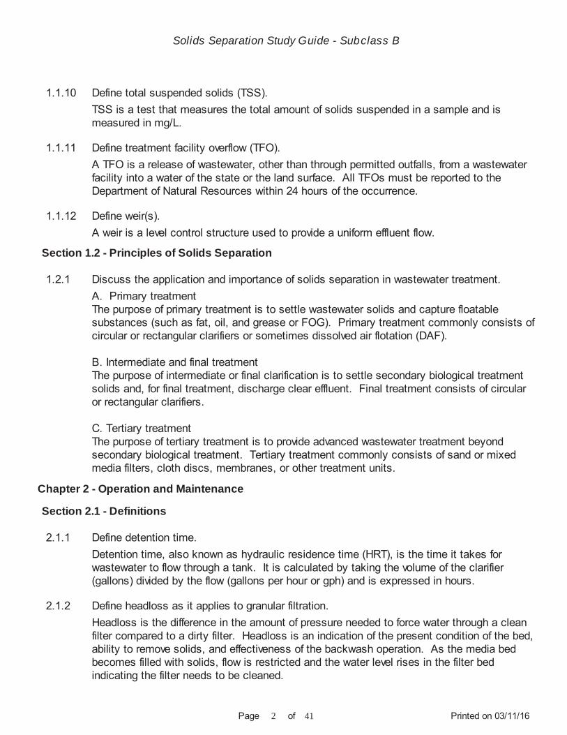
TSS is a test that measures the total amount of solids suspended in a sample and is measured in mg/L.
A TFO is a release of wastewater, other than through permitted outfalls, from a wastewater facility into a water of the state or the land surface. All TFOs must be reported to the Department of Natural Resources within 24 hours of the occurrence.
A weir is a level control structure used to provide a uniform effluent flow.
A. Primary treatmentThe purpose of primary treatment is to settle wastewater solids and capture floatable substances (such as fat, oil, and grease or FOG). Primary treatment commonly consists of circular or rectangular clarifiers or sometimes dissolved air flotation (DAF).
B. Intermediate and final treatmentThe purpose of intermediate or final clarification is to settle secondary biological treatment solids and, for final treatment, discharge clear effluent. Final treatment consists of circular or rectangular clarifiers.
C. Tertiary treatmentThe purpose of tertiary treatment is to provide advanced wastewater treatment beyond secondary biological treatment. Tertiary treatment commonly consists of sand or mixed media filters, cloth discs, membranes, or other treatment units.
Detention time, also known as hydraulic residence time (HRT), is the time it takes for wastewater to flow through a tank. It is calculated by taking the volume of the clarifier (gallons) divided by the flow (gallons per hour or gph) and is expressed in hours.
Headloss is the difference in the amount of pressure needed to force water through a clean filter compared to a dirty filter. Headloss is an indication of the present condition of the bed,ability to remove solids, and effectiveness of the backwash operation. As the media bed becomes filled with solids, flow is restricted and the water level rises in the filter bed indicating the filter needs to be cleaned.
1.1.10
1.1.11
1.1.12
1.2.1
2.1.1
2.1.2
Define total suspended solids (TSS).
Define treatment facility overflow (TFO).
Define weir(s).
Discuss the application and importance of solids separation in wastewater treatment.
Define detention time.
Define headloss as it applies to granular filtration.
Solids Separation Study Guide - Subclass B

Printed on 03/11/16Page 3 of 41
Section 2.2 - Clarifier Methods, Equipment, and Maintenance
A sludge blanket is a layer of settled solids at the bottom of a clarifier. Sludge blanket depthrefers to the thickness of this layer.
SLR is the relationship between the solids entering the clarifier and the surface area of the clarifier. SLR is calculated by taking the suspended solids entering the clarifier (pounds) divided by the surface area of a clarifier (ft²) and is expressed in pounds per square feet (lbs/ft²).
SOR is the relationship of the flow into a clarifier to the surface area of the clarifier. SOR is calculated by taking the daily flow (gallons per day or gpd) divided by the surface area of a clarifier (ft²) and is expressed in gallons per day per square foot (gpd/ft²).
WOR is the flow in relation to weir length. WOR is calculated by taking the flow (gpd) divided by the weir length (ft) and is expressed in gallons per day per foot (gpd/ft).
A. Primary clarifierThe purpose of a primary clarifier is to remove settable solids and fat, oil, and grease (FOG) from the influent and any returned flows. Some biochemical oxygen demand (BOD) is removed in this process. The solids that settle in primary clarifiers and FOG skimmed off the surface are removed from the liquid treatment process. Primary clarification should remove 40% to 60% of overall suspended solids.
B. Intermediate clarifierThe purpose of an intermediate clarifier is to settle biological solids and is found between a primary and final clarifier. The intermediate clarifier usually follows an attached-growth process.
C. Final clarifierThe purpose of a final clarifier is to settle secondary biological treatment solids and discharge clear effluent. The settled solids can be returned to the aeration tank or wasted for biosolids and sludge processing. The final clarifier is the last clarifier after the secondary treatment process.
Even flow splitting to multiple clarifiers is important from both the hydraulic and organic standpoint. Unequal flows will cause changes in detention times, weir overflow rates (WOR), sludge collection volumes, and the primary effluent quality.
2.1.3
2.1.4
2.1.5
2.1.6
2.2.1
2.2.2
Define sludge blanket depth.
Define solids loading rate (SLR).
Define surface overflow rate (SOR).
Define weir overflow rate (WOR).
Discuss the process of primary, intermediate, and final clarifiers.
Discuss the importance of even flow splitting to several clarifiers.
Solids Separation Study Guide - Subclass B

Printed on 03/11/16Page 4 of 41
In conventional activated sludge systems, primary clarifiers are used to remove settleable solids and FOG, allowing the non-settled portion to be further treated in the aeration basin.Without primary treatment, a greater amount of activated sludge is produced and final effluent quality may be impaired.
In extended aeration systems (such as oxidation ditches), primary treatment may not be used. A higher solids concentration is held and the plant may be capable of handling shock and peak loads without upsetting plant operations.
Primary treatment is necessary prior to an attached-growth process. Without proper removal, excessive solids can accumulate and clog the media causing organic overloading,anaerobic conditions, ponding, and fouling. Primary treatment also serves to reduce organic loading and remove grease, which can hinder biological growth on the media.
The sludge removal rate is primarily dependent upon depth and concentration of the sludge. Additional items to consider include:
A. Common to all clarifiers 1. Sludge depth 2. Sludge concentration 3. Sludge stability 4. Wastewater temperature 5. Clarifier design 6. Pumping frequency
B. Specific to primary clarifiers 1. Sludge process destination (thickening, treatment, or dewatering) 2. Sludge blanket, decomposition, and denitrification
C. Specific to final clarifiers 1. Sludge wasting rate (wasted activated sludge or WAS) 2. Sludge return rate (recycled activated sludge or RAS)
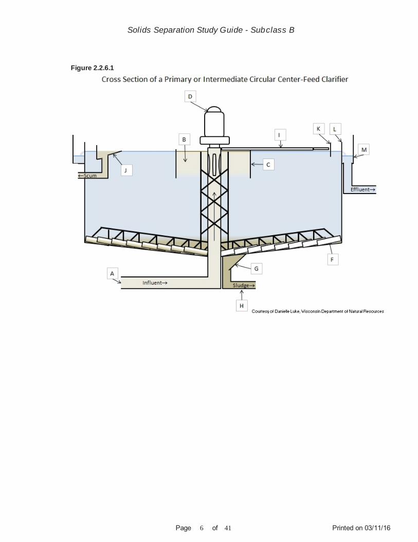
A. Influent pipeConveys the wastewater up the center of the clarifier to the influent well
B. Influent wellReceives the influent, reduces the flow velocities to not disturb settling, and evenly distributes the influent across the upper portion of the clarifier
C. Influent baffle
2.2.3
2.2.4
2.2.5
2.2.6
Discuss the use of primary clarifiers in a suspended growth (activated sludge) system.
Describe the function of primary clarifiers in an attached-growth system.
List the items to consider when determining the correct sludge removal rate.
Describe the components of a circular clarifier.
Solids Separation Study Guide - Subclass B
Printed on 03/11/16Page 5 of 41
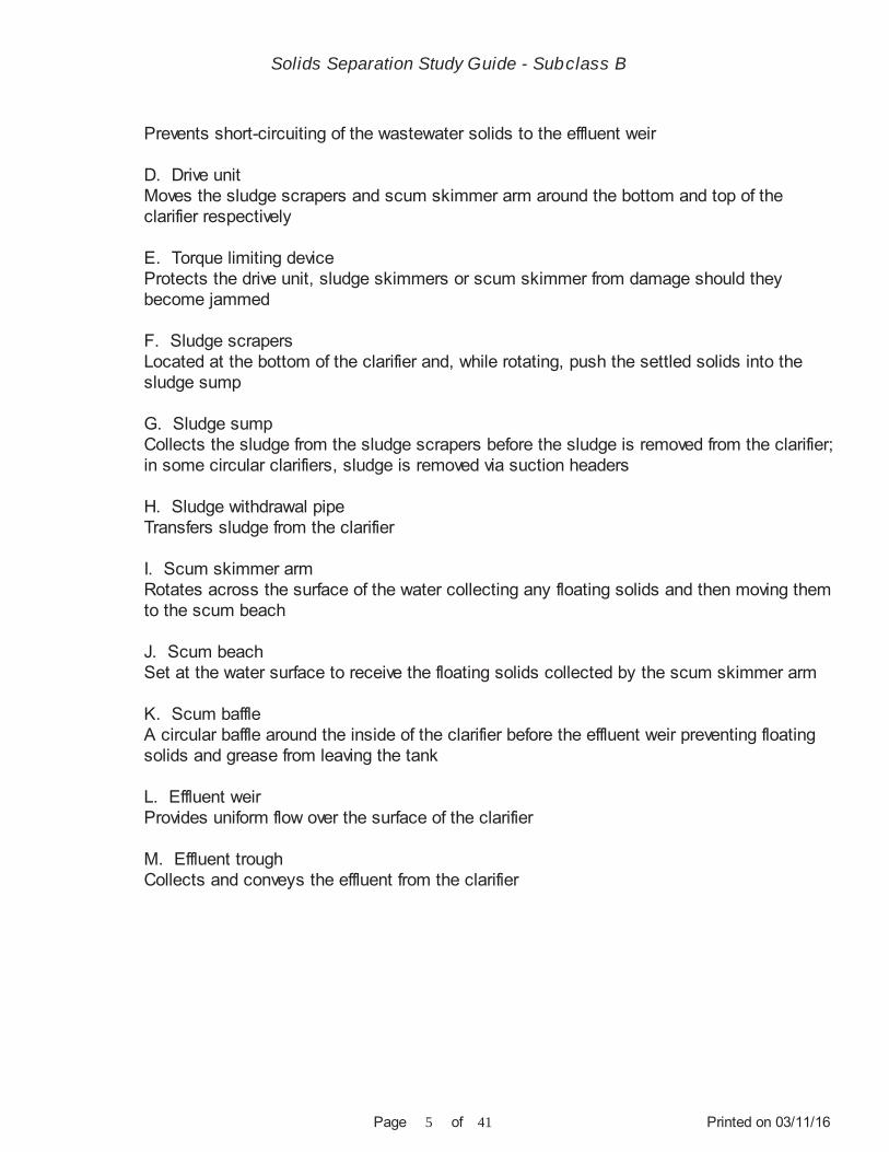
Prevents short-circuiting of the wastewater solids to the effluent weir
D. Drive unitMoves the sludge scrapers and scum skimmer arm around the bottom and top of the clarifier respectively
E. Torque limiting deviceProtects the drive unit, sludge skimmers or scum skimmer from damage should they become jammed
F. Sludge scrapersLocated at the bottom of the clarifier and, while rotating, push the settled solids into the sludge sump
G. Sludge sumpCollects the sludge from the sludge scrapers before the sludge is removed from the clarifier;in some circular clarifiers, sludge is removed via suction headers
H. Sludge withdrawal pipeTransfers sludge from the clarifier
I. Scum skimmer armRotates across the surface of the water collecting any floating solids and then moving them to the scum beach
J. Scum beachSet at the water surface to receive the floating solids collected by the scum skimmer arm
K. Scum baffleA circular baffle around the inside of the clarifier before the effluent weir preventing floating solids and grease from leaving the tank
L. Effluent weirProvides uniform flow over the surface of the clarifier
M. Effluent troughCollects and conveys the effluent from the clarifier
Solids Separation Study Guide - Subclass B
Printed on 03/11/16Page 6 of 41
Figure 2.2.6.1
Solids Separation Study Guide - Subclass B

Printed on 03/11/16Page 7 of 41
Figure 2.2.6.2
Figure 2.2.6.3
A. Influent pipeConveys the wastewater into the clarifier
B. Target baffleDistributes the influent evenly across the width of the clarifier
2.2.7 Describe the components of a rectangular clarifier.
Solids Separation Study Guide - Subclass B

Printed on 03/11/16Page 8 of 41
C. Drive unitMoves the flight and chain system
D. Flight and chainFlights are moved by the chain along the bottom of the clarifier pushing settled solids and across the top to collect floating solids
E. Wear shoePrevents wear on the flights (not shown in the diagram)
F. Sludge sumpCollects the sludge moved by the flight
G. Sludge cross collectorDrags sludge to the deep end of the sump for removal by the sludge pump
H. Scum troughCollects scum removed by the flight
I. Scum bafflePrevents floating solids and grease from flowing over the weirs
J. Effluent weirsProvides uniform flow over the surface of the clarifier
K. Effluent troughCollects and conveys the effluent from the clarifier
Solids Separation Study Guide - Subclass B

Printed on 03/11/16Page 9 of 41
Figure 2.2.7.1
A. ChainsChains can stretch, loosen, and become worn. Check for chain wear and flip the chain or replace if needed. Stretched or loose chains can be adjusted with chain adjusters or by removing links.
B. Flights and shoesClarifier flights or shoes will wear over time and need to be replaced to avoid alignment issues.
C. SprocketsA sprocket needs to be replaced if missing any teeth or excessively worn.
A. Pump sludge 1. Centrifugal 2. Progressive cavity 3. Diaphragm 4. Rotary lobe
B. Recirculate sludge 1. Centrifugal (most common) 2. Progressive cavity 3. Rotary lobe
2.2.8
2.2.9
Discuss the maintenance needs for rectangular clarifiers.
List the normal types of pumps used to pump and recirculate sludge.
Solids Separation Study Guide - Subclass B

Printed on 03/11/16Page 10 of 41
Check with the manufacturer's O&M manual for operational procedures.
For further information about these types of pumps, refer to the Wisconsin DNR General Wastewater Study Guide.
A. Inventory and label all equipmentB. Use O&M manuals for preventative maintenance tasks and frequenciesC. Establish a preventative maintenance record keeping system for maintenance schedules and history of repairs and maintenance for each piece of equipment D. Establish a follow-up system to ensure maintenance is performedE. Have a spare parts inventory
A. Amount of floating solids and gas bubbles on the water surfaceB. Flow over the weirs is even and unobstructed, clear blockages from the weirs if neededC. Skimmer arm is rotating smoothlyD. Scum beach is unobstructed, draining well and has no ice buildup in colder weatherE. Equipment is not leaking oil and has no unusual noisesF. Measure the sludge blanket depthG. Check the scum pit level and pump down if neededH. Clean algae buildup from weirs, effluent trough, scum baffle, and tank walls
A. Level weirsB. Algae or scum buildupC. CorrosionD. Warped or broken bafflesE. Surface currents
Weirs are designed to be level and clean allowing effluent to flow evenly, decreasing short-circuiting and ensuring uniform solids settling. Short-circuiting can be caused by weirs clogged with debris, algae, or solids leaving the water to flow to the path of least resistance.The debris, algae, and total suspended solids (TSS) also contain phosphorus, thus increasing the effluent phosphorus numbers. Clean weirs also make for a better appearance and improved public perception.
A. Weir overflow rate (WOR)WOR is the amount of water flowing over the weir per linear foot of weir length (gallons per day (gpd)/ft). Flow over the weirs should be even. If part of the weir is clogged and restricts flow, the flow over other sections of the weir will be faster. This may draw solids up and overthe weir.
2.2.10
2.2.11
2.2.12
2.2.13
2.2.14
Describe a preventative maintenance system for solids separation equipment.
List the daily observations of a clarifier.
List the items to check when inspecting primary weirs and baffles for proper function.
Discuss reasons for cleaning clarifier weirs.
Discuss the operational significance of weir overflow rates (WOR), solids loading rate (SLR), and surface overflow rate (SOR) in a clarifier.
Solids Separation Study Guide - Subclass B

Printed on 03/11/16Page 11 of 41
Section 2.3 - Granular Filtration Methods, Equipment, and Maintenance
B. Solids loading rate (SLR)SLR is the amount of solids per day that can be removed per square foot of surface area bya clarifier (lbs/day/ft²). If the SLR increases above the design limits of the clarifier, there will be an increase in effluent solids.
C. Surface overflow rate (SOR) SOR is the gallons per day per square foot (gpd/ft²) of clarifier surface area. A SOR that is too high will cause solids to be discharged with the effluent. A SOR that is too low may cause a long detention time and septicity.
In the absence of oxygen, a sludge blanket that is too thick and remains in the clarifier too long can denitrify. Nitrates in the sludge will be converted to nitrogen gas. The release of nitrogen gas will cause small gas bubbles that will be observed at the clarifier surface.Clumps of sludge may also rise to the surface. The free nitrogen gas attaches to the sludgemaking it buoyant.
When there are too many mixed liquor suspended solids (MLSS) in the system, the solids settling in the final clarifier may hinder the settling of solids above them. There are just too many solids in the water column to settle well. This can be observed in 30-minute settling tests and the tests will usually be high (greater than 800 mL/L). To differentiate a settling problem caused by hindered settling versus excessive filaments, an operator can do a diluted settleability test by diluting the mixed liquor sample in half (50%) with clear final effluent. If the 30-minute settleability test and settling curve improves; this indicates that withless solids, settling is better. Additional wasting would be warranted. If settling does not improve after diluting the sample, filaments may be present and the operator should use their microscope for filamentous organism identification.
The purpose of granular filtration is to provide advanced wastewater treatment beyond secondary biological treatment by removing fine particles from the effluent through adsorbtion and is most commonly used in treatment plants with more stringent effluent limits. There are two notable types of granular filtration, shallow-bed filters and deep-bed filters.
Shallow-bed filters consist of fine sand media (less than 18 inches deep). Particles are collected on or near the media surface as the effluent moves through the filter. The majority of the solids particles are collected in the upper part of the filter media.
Deep-bed filters have layered media (ranging from 30 to 48 inches) that may consist of anthracite, coarse sand, fine sand, or garnet. These layers may be one media type throughout or a different media type for each layer. The effluent flows through the deep-bed filter from the top, smaller layer of media to the bottom, coarser layer of media.
2.2.15
2.2.16
2.3.1
Discuss the significance of denitrification occuring in a clarifier.
Discuss hindered settling and how to determine if this may be occuring.
Describe the process of granular filtration.
Solids Separation Study Guide - Subclass B

Printed on 03/11/16Page 12 of 41
Figure 2.3.2.1
The overall efficiency in removing pollutants by filtration could exceed 95% removal of suspended solids and phosphorus. An alternative to granular filtration is disc filtration or other patented physical or chemical processes.
A. MediaThe media provides filtering to remove suspended solids
B. UnderdrainThe underdrain collects the filtered water and conveys the water away from the filter
C. Wash water troughThe wash water troughs convey the backwash water from the filter when in backwash.When in service, the troughs feed the influent to the media
D. Media supportThe media support prevents the media from entering the underdrain system. Depending onthe type of filter, the support can include gravel bed, media retaining strainers, or, in the case of shallow-bed filters, various forms of porous plates.
A backwash would be scheduled based on headloss, time in service, or total flow through the filter. Typically, a deep-bed filter can operate longer before needing to be backwashed.
2.3.2
2.3.3
Show and discuss the components of granular filtration.
Discuss the recommended schedule for backwashing shallow- and deep-bed filters.
Solids Separation Study Guide - Subclass B

Printed on 03/11/16Page 13 of 41
Backwashing is necessary for the removal of solids that are trapped in the media. The buildup of trapped solids will increase headloss. Without backwashing, breakthrough of the solids will occur. Frequency of backwashing is dependent on the solids loading to the filter.
During a backwash cycle, the flow through the filter is reversed with the backwash water entering the under drain system and flowing upward through the media. The backwash water is directed to the waste drain line that goes to the backwash tank or to the head of theplant. For exact steps in backwashing particular types of filters, consult the manufacturer’s O&M manual.
A. Excessive solids buildup in the mediaB. Poor backwashing practices (surface clogging)C. Excessive chemical additionsD. Poor operations of upstream treatment unitsE. Channeling (short-circuiting)
A. Headloss through the filterB. Turbidity of the effluentC. Suspended solids in the effluentD. Loss of filter media in the effluent, underdrains, and backwash basinsE. All gauges and flow metersF. Quality of the filter influentG. Any floating solids (including any oil and grease)
A. Backwash pumps and pipingB. Compressors and piping for air scourC. Pumps, piping, and nozzles for surface jetsD. Traveling bridge and associated equipmentE. Chlorine handling equipment and pipingF. Operating controls and recorder chart gauges for filtersG. High and low water level alarmsH. Underdrain system cleaning and repairI. Media cleaning or replacementJ. Surface coatings (as required)K. Maintenance of wastewater storage tanksL. Maintenance of waste washwater tanks
Consult the O&M manual for the preventative maintenance tasks and scheduling of all equipment used for granular filtration.
2.3.4
2.3.5
2.3.6
2.3.7
2.3.8
Describe the purpose and steps of backwashing granular filters.
List the operational factors that affect the filtration rate of a granular filter.
List the daily observations of granular filtration.
List the maintenance items for granular filtration.
Outline a procedure to take a filter out-of-service for an extended period of time.
Solids Separation Study Guide - Subclass B

Printed on 03/11/16Page 14 of 41
The following steps should be taken:
A. Thoroughly backwash the filterB. Chlorinate the filter (5 to 15 mg/L) and let stand for 2 to 3 days to kill biological growthsC. Thoroughly backwash the filterD. Open drain valve and allow to drainE. Store the filter wet; if the filter is stored dry the operator should remember to use the proper start-up procedure for a new or dry filter
To start a filter that has been out of service for a length of time, fill slowly from the bottom up utilizing the underdrain system (shallow bed) and the back wash system (deep bed). This allows air to be pushed from the media.
Follow the O&M manual for additional start-up procedures.
The suspended solids loading to the filter is dependent on good secondary system operations and most importantly the final clarifier. A well-operated and properly utilized finalclarifier(s) should minimize suspended solids loading to the filter and extend filter run times.
A. Causes of surface binding 1. Excessive suspended solids loading rates 2. Large particle size in relation to media size 3. Excess chemical use (polymers, precipitants, etc.) 4. Media effective size is too small
B. Problems of surface binding 1. Short filter runs 2. Increased operational costs 3. Overload upstream processes from excessive back washing 4. May cause a condition known as negative head; this causes air entrapment in lower levels which can cause media loss or mixing during backwash
Granular filter backwashing duration should be such that the media is effectively cleaned.Filter backwashing should not be too long (causing hydraulic overloading to the head of the plant and media loss) or too short (causing filter media to become built-up with solids).
A. Retrofit into existing locationB. Smaller footprintC. Lower head requirementsD. Removal of finely suspended particles for low level phosphorus requirementsE. Potentially less maintenance and backwash water
2.3.9
2.3.10
2.3.11
2.3.12
2.3.13
List the items to consider in starting up an granular filter that has been out of service.
Describe the impact of upstream processes on the operation of a granular filter.
List the causes and problems of surface binding of a granular filter.
Discuss some operational concerns related to granular filter backwashing.
List the considerations of using a disc filter over a granular filter.
Solids Separation Study Guide - Subclass B

Printed on 03/11/16Page 15 of 41
A. Fully submerged disc filtersFully submerged disc filters are a popular alternate to conventional granular media filtration technology for secondary granular filtration because they typically have less of a footprint (in other words, take up less floor space). Disc filters use cloth material to filter out fine solids remaining in effluent. The cloth medium is made out of nylon fibers or woven polyester and has a typical pore size of 10 μm. Cloth material creates the faces of the discs. A submerged disc filter will have 1 to 12 vertically mounted discs with a diameter of 1 to 3 ft.
Fully submerged disc filters operate on an outside to inside flow method. During filtration, wastewater flows through the cloth membrane by gravity and enters the filter discs from bothsides while solids are retained on the outside of the disc. Once inside the discs, the water flows to a common hollow tube in the center of the disc which conveys filtered effluent out of the filter system. The filters are at rest during the cycle which allows larger solids to also settle to the bottom of the tank. Settled solids are occasionally pumped to the head works or solids processing.
During the backwash cycle, solids are removed from the cloth material by liquid suction. A vacuum apparatus is located on both sides of the disc to apply liquid suction. Typically 1 or 2 discs are backwashed at a time allowing for filtration through the remaining discs. This allows for continuous operation of the system.
B. Partially submerged disc filtersPartially submerged disc filters are similar in operation to fully submerged disc filters exceptthe direction of the flow and depth of submergence. During normal operation, discs are only60% to 65% submerged. Partially submerged filters operate on inside to outside flow method. Wastewater flows into the filter disc from the center drum by gravity. Clean water exits the disc by passing through the cloth media and entering the collection tank. Solids are retained within the disc.
The backwash cycle initiates when water in the center drum reaches to a specific depth because of solids buildup on the media surface. As the disc rotates, nozzles spray clean effluent on to the disc, washing solids into a collection trough. Solids are then sent to the head works or solids processing.
To view an online video of a disc filter visit:https://youtu.be/tyW_ZudaCTY
The main components of a disc filter include:
A. Influent pipe and weirThe influent pipe moves the wastewater over the weir where it is then distributed evenly into the filter tank.
B. Filter tank
2.3.14
2.3.15
Describe the operating principles of disc filters.
Describe the components of a disc filter.
Solids Separation Study Guide - Subclass B

Printed on 03/11/16Page 16 of 41
Figure 2.3.15.1
The filter tank holds the influent until it is pushed through the cloth media at the same time allowing some solids to settle.
C. DiscsThe discs hold the cloth media used for removing the suspended solids.
D. Effluent pipeOnce filtered, the wastewater moves through the disc and into the effluent pipe.
E. Effluent tankThe effluent tank receives the wastewater from the effluent pipe where it flows over a weir and away from the filter.
F. Backwash systemThe two backwash pumps pull the solids off of the rotating cloth media discs and through thesuction manifolds. Some systems continuously backwash while the filter is online.
G. Solids collection systemThe settled solids are collected off the bottom of the tank using one of the same pumps used for backwashing.
Solids Separation Study Guide - Subclass B

Printed on 03/11/16Page 17 of 41
Section 2.4 - Dissolved Air Flotation Methods, Equipment, and Maintenance
Figure 2.3.15.2
Filter media is typically chemically cleaned every 3 to 6 months depending on use to remove solids trapped in the cloth media and deep cleaned with stronger chemicals as needed. Filter media panels may also need to be replaced periodically. Refer to the manufacturer's O&M manual for additional maintenance activities.
The purpose of DAF in the liquid treatment train is to help clarify or remove suspended solids from wastewater, and can be rectangular or circular. Removal is achieved by dissolving air in wastewater (under pressure at the bottom of the tank). The air released forms tiny bubbles that adhere to the suspended matter and float to the surface/top of the tank where it is removed by a skimmer. Ferric chloride and aluminum sulfide are sometimes used to enhance the solids capture. Bottom sludge collectors are used to remove any settled sludge or grit.
A. Air tankThe air tank over saturates the recycled and influent wastewater with air using high pressure
B. DAF tankIn the tank, the solids particles adhere to the air releasing from the over-saturated
2.3.16
2.4.1
2.4.2
Describe the maintenance of disc filters.
Discuss the process of dissolved air flotation (DAF).
Describe the components of DAF.
Solids Separation Study Guide - Subclass B

Printed on 03/11/16Page 18 of 41
Figure 2.4.2.1
wastewater and rise to the surface, while larger particles settle to the bottom
C. Top skimmer systemThe top skimmer system removes the floating solids by moving them into the sludge tank
D. Bottom skimmer systemThe bottom skimmer system moves the larger particles that have settled to the bottom of thetank to the settled solids tank
E. Effluent discharge chamberThe DAF effluent, no longer over saturated with air, moves past the effluent baffle and leaves the DAF through the effluent discharge chamber
F. Effluent baffleEffluent moves past the effluent baffle and into the effluent discharge chamber
All of the above items require maintenance. Please consult the facilities O&M manual for specific tasks.
A well performing DAF unit can capture more than 95% of suspended solids. The float solids concentration is typically 2% to 5%.
A. Advantages 1. High solids loading and capture rate 2. Float can be dewatered without further thickening 3. Shorter detention time when compared to a clarifier 4. Smaller construction footprint when compared to a clarifier 5. Good industrial pretreatment prior to discharge to sanitary sewer systems 6. Works well for many industrial wastewaters high in solids and fats, oils, and grease
2.4.3
2.4.4
Discuss the solids removal efficiency in a DAF.
Discuss the advantages and disadvantages of DAF.
Solids Separation Study Guide - Subclass B
Printed on 03/11/16Page 19 of 41
Section 2.5 - Membrane Systems Methods, Equipment, and Maintenance
(FOG)
B. Disadvantages 1. More complex than a clarifier 2. Higher maintenance and operational cost than a clarifier 3. Higher construction capital cost 4. Requires a cover or housing
The purpose of a membrane pressure system is to filter solids from wastewater by size exclusion. Pressure is used to force water through a semi-permeable membrane while fine solids are retained. Solids are removed from the membrane via backwash. Pressure systems are often used for ultra-low phosphorus removal.
A. Membrane surface area (ft²)Total surface area of the filters across which solids (mixed liquor suspended solids or MLSS) and particles are filtered
B. Membrane flux (gpd/ft²)Membrane flow across membranes (as measured by flow meter) per membrane surface area
C. Trans-membrane pressure (pounds per square inch or psi)Pressure across the membrane filter or headloss through the filter
D. Permeability ((gpd/ft²)/psi)Flux divided by trans-membrane pressure
E. Integrity testLeak identification
F. Time to filterAmount of time required to filter a certain volume of solids (mixed liquor suspended solids or MLSS)
A membrane is a pressure driven, solids separation device to remove very fine particles from the water. It is a physical barrier that retains particles up to a certain pore size from going through the membrane, in effect acting like a fine sieve or net in trapping particles.
A. Microfiltration (0.1 to 10.0 micrometers)B. Ultrafiltration (0.01 to 0.1 micrometers)
2.5.1
2.5.2
2.5.3
Discuss the process of membrane pressure systems.
Discuss some of the important terms and process control parameters specific to membrane bioreactors (MBR).
List the types of membrane separation technologies and their pore size range.
Solids Separation Study Guide - Subclass B

Printed on 03/11/16Page 20 of 41
Figure 2.5.3.1
Figure 2.5.3.2
C. Nanofiltration (0.001 to 0.01 micrometers)D. Reverse osmosis (less than 0.0001 micrometers)
A. Spiral wound (most common) B. Plate and frame C. Capillary fiberD. Tubular
2.5.4 List the type of membrane elements and their components used in wastewater treatment and re-use.
Solids Separation Study Guide - Subclass B

Printed on 03/11/16Page 21 of 41
Figure 2.5.4.1
Fouling is the most common performance limiting factor and failures of membrane systems.It can result from the accumulations of solids, precipitated salts or hydroxides, insoluble organics such as fats, oil, and grease (FOG); thus blocking pores on the surface of the membrane. Optimizing membrane performance and reducing fouling potential necessitatesfine screening and grit removal at the head works, FOG control, and proper dose of any chemical additions.
Fouling is controlled by membrane cleaning. Common cleaning methods, especially for membrane bioreactors, include:
A. Air scouring dailyB. RelaxationC. BackwashD. Maintenance cleaning every 1 to 2 weeksE. Chemical clean-in-place (CIP) every 3 to 6 months
An operator should consult the manufacturer's O&M manual for the cleaning methods and schedule for their specific type of membrane system.
A. Pretreatment Fine screening is a critical component of a MBR plant to reduce fouling/plugging and cleaning cycles, and to extend membrane life. Fat, oil, and grease (FOG) control is also important.
B. Membrane fluxThe membrane flux (amount of flow through the membrane surface area) is affected by membrane type, MLSS filterability, trans-membrane pressure, wastewater temperature, degree of membrane fouling, and peak flows. Plants with high and variable peak flows (greater than 2 to 1) will adversely affect the optimal flux needed. Controlling peak flows is
2.5.5
2.5.6
Discuss membrane fouling and cleaning methods.
Discuss optimization factors of membrane bioreactor systems (MBR).
Solids Separation Study Guide - Subclass B

Printed on 03/11/16Page 22 of 41
Section 2.6 - Process Variations
Figure 2.5.8.1
imperative for MBR plants.
C. Mixed liquor suspended solidsMBR plants operate at much higher MLSS concentrations because solids are separated from the liquid by membranes, not gravity. MBRs commonly operate at MLSS concentrations between 8000 to 15,000 mg/L, some even higher. However, too high a MLSS concentration can impact membrane performance for various reasons. With increasing MLSS concentrations in the aeration basins, MBR operating membrane pressures can be reduced by fouling. It can also result in foaming. Reducing the MLSS concentrations through increased wasting will improve operating pressures and decrease fouling. Consistent and optimal membrane performance is achieved by balancing the solidsloading (flow and solids concentration) across a membrane surface.
Membrane bioreactors consist of submerged units placed within the end of activated sludgeaeration basins or in their own tankages after the aeration basins. Each submerged membrane unit consists of a tube, manifold, membrane case, membrane cartridge, diffuser case, and diffuser. Basic MBRs consist of flat plate or hollow fiber membranes. Each has their advantages/disadvantages. Flat plats require a thin biofilm to develop on the membrane while hollow fiber does not. A continuous cross flow of mixed liquor suspended solids and air provides for an optimum biofilm thickness on the membranes.
A wastewater treatment plant that uses membrane bioreactors within its treatment train combines aeration, clarification, and filtration (solids separation) into a single step (reducedfootprint). The membranes can be installed and operated within an aeration basin with a very high MLSS concentration (6,000 to 12,000 mg/L MLSS) and produce a very high quality effluent in biochemical oxygen demand (BOD), total suspended solids (TSS), and nutrients.
Raw wastewater is drawn into a primary mixing zone in the vertical draft tube where it is mixed with coagulants. Wastewater then flows into the reaction-flocculation zone where it is
2.5.7
2.5.8
2.6.1
Discuss the components of a MBR submerged membrane unit.
Discuss the treatment train configuration of a plant with MBRs.
Discuss the process of up-flow reactors.
Solids Separation Study Guide - Subclass B

Printed on 03/11/16Page 23 of 41
Chapter 3 - Monitoring, Process Control, and Troubleshooting
Section 3.1 - Definitions
Section 3.2 - Sampling and Testing
mixed with partially recirculated settled solids. Some of the flow is recirculated to the mixing zone, and some of the flow goes to the clarification zone where decreasing velocities are nolonger sufficient to keep the flocculated solids suspended. Concentrated sludge is removed to the sludge hopper. Clear water flows over the weir.
Breakthrough is when solids push through the granular filter media and out through the effluent, uncaptured. This occurs when a filter is run too long with insufficient backwashing, becomes overly adsorbed with solids, and headloss increases.
Filter channeling occurs when portions of the filter plug and the wastewater flows in channels, reducing treatment efficiency.
Sludge age is the theoretical length of time a particle of activated sludge stays in the treatment plant, measured in days. In an activated sludge plant, sludge age is the amount (lbs) of mixed liquor suspended solids (MLSS) divided by the suspended solids, or excess cell mass, withdrawn from the system per day (lbs per day of waste activated sludge or WAS).
Washout is the loss of solids from any treatment process due to high flows.
The two primary control measurements for granular filtration are effluent turbidity and filter headloss. Filter effluent turbidity is an indirect measurement of suspended solids and can be measured quickly. Filter headloss is the determining factor for backwashing providing there are no other operational problems (channeling or breakthrough). Between effluent turbidity and filter headloss, total operations of granular filters can be done without additional laboratory testing.
A. In field 1. Solids profiling 2. Dye testing 3. Drogues (submerged, flow-field indicators)
B. Performance calculations 1. Surface overflow rates 2. Weir overflow rates
3.1.1
3.1.2
3.1.3
3.1.4
3.2.1
3.2.2
Define breakthrough.
Define filter channeling.
Define sludge age.
Define washout.
Discuss the two primary control measurements for granular filtration.
List methods used to evaluate the performance of clarifiers.
Solids Separation Study Guide - Subclass B

Printed on 03/11/16Page 24 of 41
Section 3.3 - Data Understanding and Interpretation
3. Solids loading rates
To evaluate the grit in sludge, an operator can analyze the sludge for fixed suspended solids. If a high level of grit is found in the primary clarifier sludge, an operator should evaluate the grit removal system.
The most common method for measuring loss of media is to measure from a fixed point (wash water trough or top of wall) to the surface of the filter media. Another indirect method is to check the backwash water tank for filter media settled at the bottom of the tank.
A. Visually check and sample the total suspended solids (TSS) of the backwash water at the beginning and end of the backwash cycles.B. Measure headloss before and after a backwash.C. If having chronic backwash inefficiencies, take a core or shovel sample to examine the media.
Take a core sample of the media. The core sample can be used to determine the media profile to assure proper grading after backwashing, it can be used to check media depth, and used to check for proper media cleaning after backwashing.
The goal for pumping sludge from a primary clarifier is to obtain 3% to 5% solids for optimalanaerobic digester operation. Pumping sludge too fast can create poor quality thin sludge. Pumping sludge infrequently can create a thick sludge, resulting in clogging problems, anaerobic conditions (gas bubbles and floating sludge), and undesirable loadings for the anaerobic digester.
The sludge blanket in the final clarifier is usually kept between 1 to 3 feet. A sludge blanket that is too deep may cause denitrification to occur. This would result in solids floating to the surface and be lost over the weir.
Sludge blanket depth is measured using a sludge depth indicator. One such common device is a Sludge Judge®.
A settleability curve can be graphed using the results of the 30-minute settling test. The shape of the settling curve indicates the settling characteristics of the activated sludge in a final clarifier. It shows how the sludge settles and is helpful in assessing settling problems.
3.2.3
3.2.4
3.2.5
3.2.6
3.3.1
3.3.2
3.3.3
Describe how to determine if grit is building up in the sludge hopper of the primary clarifier.
Describe the methods of measuring loss of media.
Discuss how to determine if backwashing is effective.
Discuss the use of a core sample in granular filters.
Describe normal primary sludge concentration and the effect on sludge quality of primary sludge pumping rates.
Discuss sludge operating depths in final clarifiers.
Graph a settleability curve of a final clarifier and discuss its meaning.
Solids Separation Study Guide - Subclass B

Printed on 03/11/16Page 25 of 41
Figure 3.3.3.1
In activated sludge aeration basins, mixed liquor suspended solids (MLSS) is expressed in milligrams per liter (mg/L) . As solids are thickened and the concentration gets to 10,000 mg/L or above, the solids are then often expressed as a percent. Every 10,000 mg/L is 1%
3.3.4 Compare activated sludge solids results expressed as milligrams per liter (mg/L) and percent solids.
Solids Separation Study Guide - Subclass B

Printed on 03/11/16Page 26 of 41
Section 3.4 - Sidestreams
Section 3.5 - Performance Limiting Factors
and can be expressed as follows:
10,000 mg/L = 1.0% solids15,000 mg/L = 1.5% solids20,000 mg/L = 2.0% solids25,000 mg/L = 2.5% solids30,000 mg/L = 3.0% solids
Wastewater should remain in the clarifier long enough to settle out most of the suspended solids. Typically, clarifier detention times will be 2 to 3 hours. This depends on the influent flowrate and size of the clarifier.
Clarifier detention times are calculated using the following formulas:
Circular clarifier volume (gals) = 3.14 × [radius (ft)]² × height (ft) × 7.48 gals/ft³Rectangular clarifier volume (gals) = length (ft) × height (ft) × width (ft) × 7.48 gals/ft³Detention time (hrs) = [tank volume (gals) ÷ flow rate (gpd)] × 24 hrs/day
A significant decrease in headloss after backwashing indicates the filter has been properly cleaned. Visual observations help the operator determine if the washwater is clean or if media is being washed out of the filter.
Backwash is returned to the head of the treatment plant similar to other sidestreams and passed through the plant for treatment. Backwash water is primarily high in total suspended solids (TSS) and can contain elevated levels of phosphorus. To moderate the flow of backwash, wastewater tanks are often used to hold flows until they can be treated. Low flowperiods can be used to minimize influent plant loadings.
A significant effect of sidestreams can be the TSS loading to primary treatment.Sidestreams from the solids processing should be kept low in TSS.
During wet weather peak flows, an operator is faced with protecting equipment and unit processes while trying to maintain treatment. The loss of solids through the final clarifiers is the most common problem from wet weather peak flow events. The key factor that controls the peak flow capacity of activated sludge systems is solids separation.
3.3.5
3.3.6
3.4.1
3.4.2
3.5.1
State the recommended detention time for primary, intermediate, and final clarifiers.
State what to observe to determine if backwashing is effective in an granular filter.
Describe how spent backwash water is handled.
Discuss the effect of sidestreams on primary treatment.
Discuss the operational problems related to hydraulic overloads from inflow and infiltration (I/I), and suggest what an operator might be able to do to maintain and maximize performance during high flow periods.
Solids Separation Study Guide - Subclass B

Printed on 03/11/16Page 27 of 41
Keys to optimum solids separation are:
A. Mixed liquor settleabilityThe key to optimizing settleability is: (1) maintaining the proper environmental conditions that favor the growth and health of good large floc-forming bacteria that settle well (not filamentous organisms) through (2) operating the treatment plant with regular and consistentprocess control.
B. Optimize clarifier performanceBe sure weirs are level and flow over them is evenly distributed. If there is more than one clarifier, the flow distribution from the aeration basins to each clarifier should be evenly distributed. Return activated sludge (RAS) rates should be set to minimize sludge blankets to less than a foot. If clarifier short-circuiting is occurring, which is usually worse during high flow periods, clarifier baffles can be considered.
C. Reduce clarifier solids loading The clarifier solids loading rate (SLR) is affected by the incoming flow and RAS flowrate.Some ways to reduce the solids loading to the final clarifier(s) is to (1) bring any extra, unused tankages on-line if they are available, such as another clarifier or aeration basin; (2) take some aeration basin(s) off-line and storing solids in them until flows subside; (3) operate the aeration basins in a step feed configuration to reduce solids at the end of the aeration basins and thus the solids entering the final clarifier, and (4) adjust the RAS rate to balance the lowest possible sludge blanket at the lowest SLR.
The best long-term strategy for maintaining wastewater treatment during wet weather periods is to reduce the amount of I/I of clear water entering into the sewer system. An ongoing collection system Capacity, Management, Operation and Maintenance (CMOM) Program should be developed and implemented.
Many of the concepts presented in this key knowledge were derived from a series of articles written by Bill Marten, Wastewater Process and Operations Engineer, Triad Engineering Inc, in the Wisconsin Wastewater Operators Association's (WWOA) “The Clarifier” (2005-2006). For complete details on ways to maximize secondary treatment wet weather capacity, the reader is referred to these six articles.
High-strength wastes come from industrial operations such as dairies, breweries, and food processors. Effluent from these industries contains significantly higher biochemical oxygen demand (BOD) as compared to domestic waste. High-strength waste can organically overload a primary clarifier by depleting the dissolved oxygen (DO) in the water. The resulting anaerobic conditions will cause odors and floating sludge. Further in the treatmentprocess, high-strength organic waste will cause additional solids production during the activated sludge process. The additional solids can cause poor supernatant return flow andincreases waste sludge hauling. When a municipality has high-strength organic waste contributors, they often require pretreatment.
3.5.2
3.5.3
Describe the effect of high-strength waste (high BOD) has on solid separation.
List operational problems caused by hydraulic overloading in a clarifier.
Solids Separation Study Guide - Subclass B

Printed on 03/11/16Page 28 of 41
Section 3.6 - Corrective Actions
A. Solids washouts If the flow is too high through the final clarifier, the solids will not have enough time to settle and can wash out over the weirs. This can result in a loss of solids from the system and effluent permit violations.
B. Reduced treatment efficiencyIf too many solids flow out of the clarifier, there may not be enough RAS solids returned back to the aeration basin to effectively treat the incoming organic load.
C. Increased weir overflow rate (WOR)High WOR can lead to a loss of solids especially when the solids settling rate is already poor.
3.6.1 Describe the causes and corrective actions for clarifier problems.
Solids Separation Study Guide - Subclass B

Printed on 03/11/16Page 29 of 41
Figure 3.6.1.1
Solids Separation Study Guide - Subclass B

Printed on 03/11/16Page 30 of 41
Figure 3.6.1.2
Figure 3.6.1.3
Fouling is a condition in which solids accumulate on top of or between the media resulting ina decreasing flow through the media. It can also occur from an increase in bio-growth in themedia or from an overuse of polymers.
3.6.2
3.6.3
Describe media fouling in a granular filter.
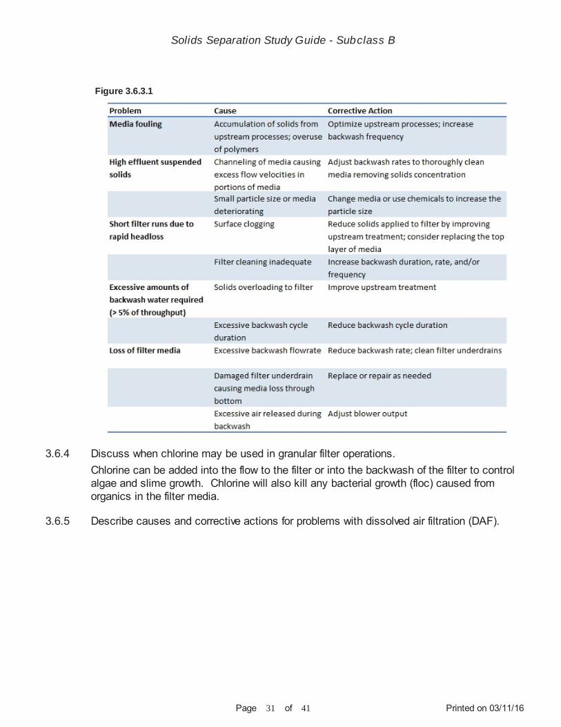
Describe the causes and corrective actions for problems with granular filtration.
Solids Separation Study Guide - Subclass B
Printed on 03/11/16Page 31 of 41
Figure 3.6.3.1
Chlorine can be added into the flow to the filter or into the backwash of the filter to control algae and slime growth. Chlorine will also kill any bacterial growth (floc) caused from organics in the filter media.
3.6.4
3.6.5
Discuss when chlorine may be used in granular filter operations.
Describe causes and corrective actions for problems with dissolved air filtration (DAF).
Solids Separation Study Guide - Subclass B

Printed on 03/11/16Page 32 of 41
Chapter 4 - Safety
Section 4.1 - Definitions
Section 4.2 - Personal Safety
Figure 3.6.5.1
Lock-out/tag-out is used to protect the operator from serious injury by ensuring that machinery remains completely off. The lock is placed on the power source in a way that prohibits the machinery from receiving the power necessary to run and includes a tag with the operator’s name performing the maintenance. Without a lock-out/tag-out system, the possibility exists that a machine will unexpectedly start-up, either because of stored energy not correctly released, being triggered by the control system, or through someone starting it without realizing maintenance is being performed.
PPE is the protective clothing and other devices designed to protect an individual while in potentially hazardous areas or performing potentially hazardous operations. Examples of PPE include, but are not limited to: gloves, hard hat, steel-toed boots, safety glasses, and other appropriate clothing.
A. Falling into tanks, especially aeration tanks where currents can pull an operator under the water surfaceB. NoiseC. Exposure to waterborne and bloodborne pathogens
4.1.1
4.1.2
4.2.1
Define lock-out/tag-out.
Define personal protective equipment (PPE).
List various safety considerations that are important when working with a solids separation process.
Solids Separation Study Guide - Subclass B

Printed on 03/11/16Page 33 of 41
D. Loose clothing around moving parts on mechanical equipmentE. Electrical hazardsF. Slippery surfaces G. Confined spacesH. Compressed air and air under a vacuumI. Chemicals and chemical equipmentJ. Hydrogen sulfide and other gasesK. High temperatures
Operators should follow all federal and state safety requirements. Safety programs and emergency procedures should be in place and followed at all times.
A. Draining a clarifier 1. Leave as little a solids blanket as possible before draining 2. Close the clarifier influent gate and tag/lock it out. If there is any other piping with valves that are connected to the clarifier being drained, make sure they are closed and lock-out/tag-out, too. 3. Open the drain valve for the clarifier. The sludge withdrawal valve may have to be opened, also. It is possible there is no drain valve and a pump may have to be used. 4. Leave the drive on for a while to scrape as much solids out as possible. The skimmer may have to be pulled up. Tag/lock out the drive after it is turned off. 5. While the clarifier is draining, make sure the pressure relief valves are operable by confirming they open. 6. If the clarifier will not drain completely, set up a portable pump to finish. The pump can also be used while hosing out the clarifier. Once the clarifier is cleaned, enter it for inspection and maintenance.
B. Entering a drained clarifier 1. Follow all confined space procedures! 2. Make sure the clarifier is cleaned out, the drive is locked-out/tagged-out and all gates or valves leading to the clarifier are also locked-out/tagged-out. 3. Before entering, wear the proper PPE (gloves, safety glasses, boots, etc.). A gas detector is also needed for confined space entry. Fill out any paperwork necessary for the job and have at least two people present. 4. A long extension ladder will probably be needed for entry. Be sure to secure it to the clarifier before entering.
If sludge is trapped in a pipe between two closed valves, bacteria in the sludge could generate gas. If the bacteria generate enough gas, the pressure inside the pipe could build up and rupture the pipe. Not only a safety concern, there is a possibility of clogging the piping system if sludge is left in the pipe over a period of time.
4.2.2
4.2.3
Discuss draining a clarifier and the function of the relief valves.
Discuss the negative consequences of leaving sludge sit in a pipe between two closed valves.
Solids Separation Study Guide - Subclass B

Printed on 03/11/16Page 34 of 41
Section 4.3 - Chemical Safety
A. Hydrogen sulfideB. MethaneC. Carbon monoxideD. Chlorine
Owners of wastewater treatment plants should clearly define all confined spaces. Operatorsshould know them and follow all confined space entry procedures. FOLLOW ALL CONFINED SPACE ENTRY PROCEDURES!
Wisconsin Department of Safety and Professional Services SPS 332 Public Employee Safety and Health must be followed. Some of the important safety requirements are:confined space, excavation, hearing conservation, blood-borne pathogens, CPR-First Aid, Safety Data Sheets (SDS), electrical, fall protection, hazardous materials, as well as others.Non-public entities follow the Occupational Safety and Health Administration (OSHA) CFR 29 part 1910.
Sampling from basins, channels, and other treatment processes puts an operator at risk of falling into the wastewater. Basins that are aerated can be the most dangerous because the aeration process makes it extremely difficult to stay afloat in waters saturated with high concentrations of air. For this reason, an operator should never extend beyond the protection of the guardrails. OSHA highly recommends ring buoys with at least 90 ft of line be provided and readily available for emergencies and strategically placed around all process basins. OSHA also recommends any operator working over or near water where arisk of drowning is present be provided with a life jacket or buoyant work vest.
Some chemicals used in wastewater treatment plants are hazardous materials and must beidentified. Safety Data Sheets (SDS) for each chemical are required to be kept onsite and readily available. In the event of a spill, the Department of Natural Resources must be contacted.
Any spill of hazardous material should be reported to the Department of Natural Resources within 24 hours and to the local emergency response agencies.
Storage tanks must have secondary containment that equals the volume of the storage tank. Place containment pails under potential leak points during unloading of delivery vehicles
4.2.4
4.2.5
4.2.6
4.2.7
4.3.1
4.3.2
4.3.3
Identify potential toxic gases at a wastewater treatment plant.
Discuss precautions for entering tanks, vessels, or other confines space areas.
Describe the applicable safety program and requirements municipal wastewater treatment plants must follow.
Discuss the importance of floatation devices at a wastewater treatment plant.
Discuss the importance of maintaining chemical delivery, storage, and usage records.
Discuss what should be done in the event of a chemical spill.
Discuss preventative spill measures and procedures when handling hazardous chemicals.
Solids Separation Study Guide - Subclass B

Printed on 03/11/16Page 35 of 41
Chapter 5 - Calculations
Section 5.1 - Clarifier
and when uncoupling fill lines. Inspect and maintain fill lines and valves. Inspect storage tanks and hardware for integrity. Pay attention to what is being done!
Provide onsite containment equipment such as absorbent booms, sandbags, etc. and seal the yard and storm drains to prevent offsite loss of chemical.
GIVEN:[MGD = million gallons per day]
Influent solids = 200 mg/LInfluent flow = 1.0 MGD
FORMULA AND SOLUTION:
Solids loading (lbs/day) = solids conc. (mg/L) × flow (MGD) × 8.34 = 200 mg/L × 1.0 MGD × 8.34 = 1,670 lbs/day
GIVEN:
Diameter = 30 ftDepth = 14 ft1 ft³ = 7.48 gals
FORMULA AND SOLUTION:
Tank volume (gals) = 3.14 × [radius (ft)]² × depth (ft) × 7.48 gals/ft³ = 3.14 × (15 ft × 15 ft) × 14 ft × 7.48 gals/ft³ = 3.14 × 225 ft² × 14 ft × 7.48 gals/ft³ = 73,985 gals
GIVEN:
Length = 50 ftWidth = 30 ftDepth = 10 ft1 ft³ = 7.48 gals
FORMULA AND SOLUTION:
5.1.1
5.1.2
5.1.3
Given data, calculate solids loading (lbs/day) to a primary clarifier.
Given the dimensions of a circular clarifier, calculate its volume (gals).
Given the dimensions of a rectangular clarifier, calculate its volume (gals).
Solids Separation Study Guide - Subclass B

Printed on 03/11/16Page 36 of 41
Tank volume (gals) = length (ft) × width (ft) × depth (ft) × 7.48 gals/ft³ = 50 ft × 30 ft × 10 ft × 7.48 gals/ft³ = 15,000 ft³ × 7.48 gals/ft³ = 112,200 gals
GIVEN:
Mixed liquor suspended solids (MLSS) = 3,600 mg/LInfluent flow = 1.03 MGDClarifier diameter = 76 ft
FORMULAS AND SOLUTIONS:[gpd = gallons per day]
Weir length = 2 × 3.14 × clarifier radius = 2 × 3.14 × 38 ft = 238.64 ft
WOR = flow (gpd/ft) ÷ weir length (ft) = 1,030,000 gpd ÷ 238.64 ft = 4,316 gpd/ft
Clarifier surface area = 3.14 × [radius (ft)]² = 3.14 × (38 ft) ² = 4,534 ft²
SLR = solids applied to clarifier (lbs/day/ft²) ÷ clarifier surface area (ft²) = (1.03 MGD × 3,600 mg/L × 8.34) ÷ (4,534 ft²) = 6.82 lbs/day/ft²
GIVEN:[NOTE: every 1% solids is the equivalent of 10,000 mg/L]
Flow = 2 MGDInfluent suspended solids (ISS) = 200 mg/LEffluent suspended solids (ESS) = 100 mg/LSludge solids concentration = 5% (50,000 mg/L)
FORMULAS AND SOLUTION:
Settled solids (lbs) = flow (MGD) × [ISS (mg/L) - ESS (mg/L)] × 8.34 = 2 MGD × (200 mg/L - 100 mg/L) × 8.34
5.1.4
5.1.5
Given the following data, calculate the weir overflow rate (WOR) and solids loading rate (SLR) of the clarifier.
Given data related to primary clarifier loading, calculate the amount of sludge (gals) that need to be pumped daily.
Solids Separation Study Guide - Subclass B

Printed on 03/11/16Page 37 of 41
= 1,668 lbs of settled solids
Settled solids (lbs) = sludge to be pumped (MGD) × solids conc. (mg/L) × 8.34[NOTE: Formula needs to be rearranged to find the amount of sludge to pump]
Sludge to be pumped [MGD] = settled solids (lbs) ÷ [solids conc. (mg/L) × 8.34] = 1,668 lbs ÷ [50,000 mg/L × 8.34] = 0.004 MGD or 4,000 gpd of sludge
GIVEN:[gpm = gallons per minute]
Pump capacity = 60 gpmPumping time = 20 mins
FORMULA AND SOLUTION:
Pumped (gals) = pump capacity (gpm) × pumping time (mins) = 60 gpm × 20 mins = 1,200 gals
GIVEN:
Pump runtime = 20 mins/hrPump capacity = 4.5 gals/strokePump strokes 4 times per minute2 clarifiers
FORMULAS AND SOLUTION:
Strokes (#/day) = [pump run time (mins/hr) × 24 hrs/day] × strokes/min = [20 mins/hr × 24 hrs/day] × 4 strokes/min = 480 mins/day × 4 strokes/min = 1,920 strokes/day
Sludge pumped (gals) = [strokes (#/day) × sludge (gals/stroke)] × 2 clarifiers = [1,920 strokes/day × 4.5 gals/stroke] × 2 clarifiers = 8,640 gpd × 2 clarifiers = 17,280 gpd
GIVEN:
5.1.6
5.1.7
5.1.8
Given data, calculate the sludge pumped (gals) when running time and capacity of pump areknown.
Given data, calculate the amount of sludge pumped (gals) from the bottom of 2 primary clarifiers using a diaphragm pump.
Given data, calculate the suspended solids or BOD percent removal.
Solids Separation Study Guide - Subclass B
Printed on 03/11/16Page 38 of 41
Primary effluent = 120 mg/LPrimary influent = 200 mg/L
FORMULA AND SOLUTION:
Percent removal = ([influent (mg/L) - effluent (mg/L)] ÷ influent (mg/L)) × 100 = [(200 mg/L - 120 mg/L) ÷ 200 mg/L] × 100 = (80 mg/L ÷ 200 mg/L) × 100 = 0.4 × 100 = 40% removal
GIVEN:
30-minute settling test = 800 mL/LMLSS = 4,000 mg/L
FORMULA AND SOLUTION:
SVI = [settled volume (mL/L) ÷ MLSS (mg/L)] × 1,000 = [800 mL/L ÷ 4,000 mg/L] × 1,000 = 0.2 × 1,000 = 200
Possible causes for high SVI: A. Filamentous organisms B. Young, poor settling sludge C. Too high a MLSS
GIVEN:
A. Rectangular clarifier Width = 20 ft Length = 40 ft Depth = 10 ft Flowrate = 532,800 gpd
B. Circular clarifier Diameter = 20 ft Depth = 12 ft Flowrate = 432,000 gpd
FORMULAS AND SOLUTION:[gph = gallons per hour]
5.1.9
5.1.10
Given treatment plant data, calculate the sludge volume index (SVI) and discuss possible causes of the result.
Given data, calculate the detention time (hrs) in a clarifier (rectangular and circular).
Solids Separation Study Guide - Subclass B

Printed on 03/11/16Page 39 of 41
Section 5.2 - Granular Filtration
A. Rectangular clarifier Clarifier volume (ft³) = width (ft) × length (ft) × depth (ft) = 20 ft × 40 ft × 10 ft = 8,000 ft³
Clarifier volume (gals) = clarifier volume (ft³) × 7.48 gals/ft³ = 8,000 ft³ × 7.48 gals/ft³ = 59,840 gals
Detention time (hrs) = clarifier volume (gals) ÷ [flowrate (gpd) ÷ 24 hrs/day] = 59,840 gals ÷ [532,800 gpd ÷ 24 hrs/day] = 59,840 gals ÷ 22,200 gph = 2.7 hrs
B. Circular clarifier Clarifier volume (ft³) = 3.14 × [radius (ft)]² × depth (ft) = 3.14 × [10 ft]² × 12 ft = 3,768 ft³
Clarifier volume (gals) = clarifier volume (ft³) × 7.48 gals/ft³ = 3,768 ft³ × 7.48 gals/ft³ = 28,185 gals
Detention time (hrs) = clarifier volume (gals) ÷ [flowrate (gpm) × 60 mins/hr] = 28,185 gals ÷ [432,000 gpd ÷ 24 hrs/day] = 28,185 gals ÷ 18,000 gph = 1.6 hrs
GIVEN:[MGD = million gallons per day][gpd = gallons per day]
Average daily flow = 0.4 MGDFilter width = 10 ftFilter depth = 12 ft
FORMULA AND SOLUTION:
Flowrate = [average daily flow (gpd) ÷ mins/day] ÷ filter area = (400,000 gpd ÷ 1,440 min/day) ÷ (10 ft × 12 ft) = 277.77 gpm ÷ 120 ft² = 2.3 gpm/ft²
5.2.1 Given data, calculate the daily filtration rate through a granular filter (gallons per minute (gpm)/ft²).
Solids Separation Study Guide - Subclass B

Printed on 03/11/16Page 40 of 41
GIVEN:
Length = 10 ftWidth = 12 ftFlow rate = 20 gpm/ft²Backwash time = 8 minsNumber of filters = 3 (each backwashed once per day)
FORMULAS AND SOLUTION:
Backwash area (ft²) = length (ft) × width (ft) = 10 ft × 12 ft = 120 ft²
Backwash flow (gpd) = backwash area (ft²) × flowrate (gpm) × backwash time (mins/day) × # of filters = 120 ft² × 20 gpm/ft² × 8 mins/day × 3 filters = 57,600 gpd
5.2.2 Given data, calculate total backwash (gpd) of a granular filter.
Solids Separation Study Guide - Subclass B

Printed on 03/11/16Page 41 of 41
References and Resources
UW WATER LIBRARY
OPERATION OF MUNICIPAL WASTEWATER TREATMENT PLANTS
OPERATION OF WASTEWATER TREATMENT PLANTS
INTRODUCTION TO WATER RESOURCE RECOVERY FACILITY DESIGN
Most of the resources listed on this page can be borrowed through the UW Water Library as part of a partnership between the UW Water Library, the Wisconsin Wastewater Operator Association (WWOA), Central States Water Environmental Association (CSWEA), and the Wisconsin Department of Natural Resources. Instructions for borrowing materials from the UW Water Library can be found by visiting the website provided below, clicking on ‘WISCONSIN RESIDENTS’, and then clicking on ‘HOW TO BORROW MATERIALS’.
Water Environmental Federation (WEF) (2008). Manual of Practice (MOP) No. 11 vol. I, II, III (6th ed.). New York, New York: McGraw-Hill
Office of Water Programs, California State University, Sacramento (2008). Operation of Wastewater Treatment Plants (7th ed.). Sacramento, California: University Enterprises, Inc., California State University
Water Environmental Federation (WEF) (2014). Introduction to Water Resources Recovery Facility Design (2nd ed.). Alexandria, Virginia: McGraw-Hill
www.aqua.wisc.edu/waterlibrary
www.wef.org
www.owp.csus.edu
www.wef.org
1.
2.
3.
4.