Embed Size (px)
Citation preview
�/7
www.visualcomponents.com
the visual components logo 3Dcreate, 3Drealize and 3Dvideo are trademarks of visual components oy, inc. all other brand names, product names, or trademarks belong to their respective holders.
the soliDworks exporter aDD-on proviDes an elementary toolsets
for transfering a geometry from soliDworks into the visual
components 3Dcreate simulation software. this manual incluDes
instructions for installation, usage anD some practical tips to get
most out of your geometry export.
InstallatIon
Before launching the solidworks add-on installer, ensure that you have the follo�ing itemsyou have the follo�ing items installed on your computer:
3Dcreate solidworks
in order to install the add-on double click on the 'SetupSolidWorksAddOn.exe' installation file. follo� the installation dialog to install the solidworks add-on.
FIrst Use
when the add-on has been installed you may need to make the visual components solidworks exporter icons visible inside solidworks. to do so, open solidworks, then click Tools -> Add-Ins. choose the visual components exporter, Both the "Active" and "Start Up Columns".
a ne� tool bar �ill be added, to enable it right click on any existing tool bar and choose visual components exporter. this �ill open a ne� tool bar �ith t�o icons, similar to the one belo�, �hich is only visible �hen a document is open.
actIvatIon
when the exporter is run for the first time, an activation dialog �ill pop up, asking for a licence key. follo� the steps of the activation dialog, to activate the solidworks add-on. after a successful activation, the add-on it is ready to be used.
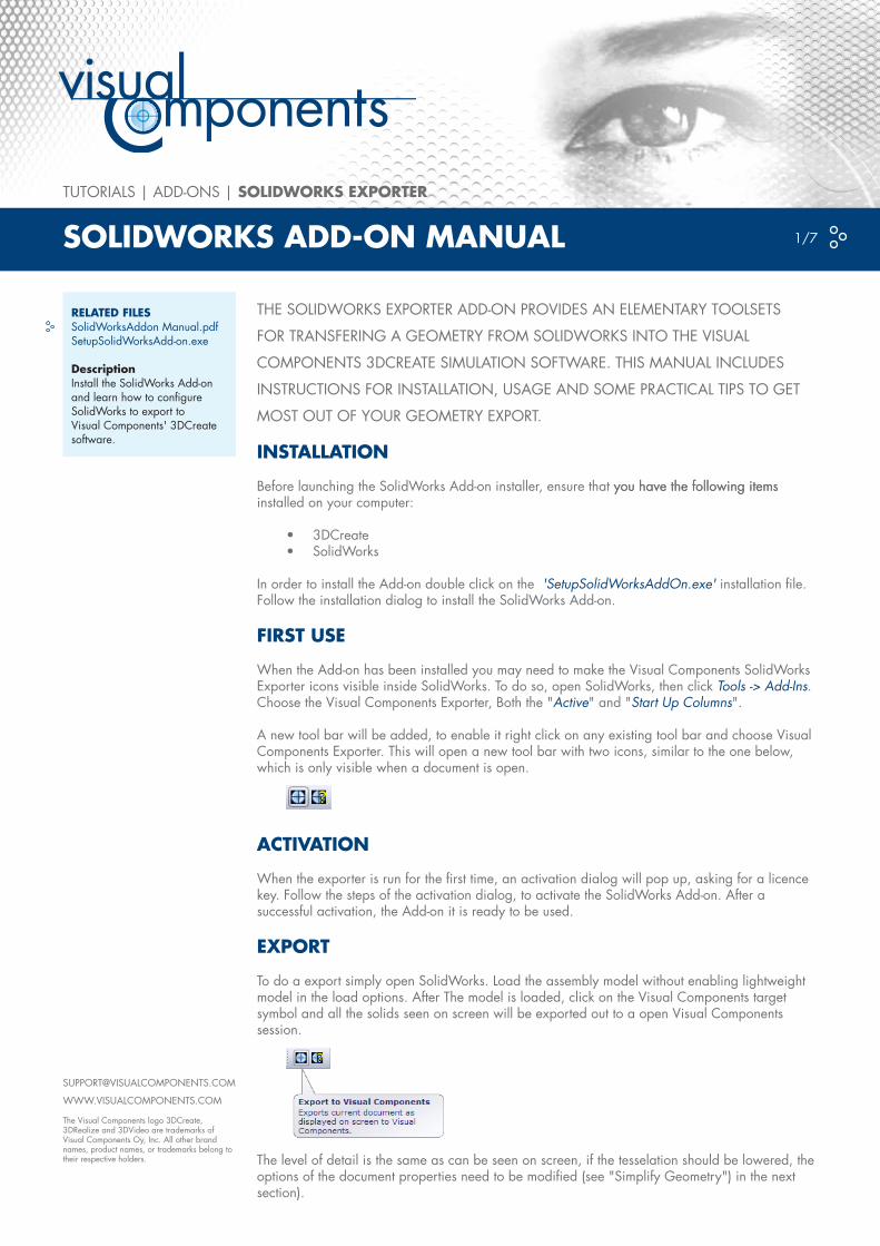
export
to do a export simply open solidworks. load the assembly model �ithout enabling light�eight model in the load options. after the model is loaded, click on the visual components target symbol and all the solids seen on screen �ill be exported out to a open visual components session.
the level of detail is the same as can be seen on screen, if the tesselation should be lo�ered, the options of the document properties need to be modified (see "simplify geometry") in the next section).
••
related FIlessolidworksaddon manual.pdfsetupsolidworksadd-on.exe
descriptioninstall the solidworks add-on and learn ho� to configure solidworks to export to visual components' 3Dcreate soft�are.
tutorials | aDD-ons | solIdworks exporter
solIdworks add-on ManUal
www.visualcomponents.com
the visual components logo 3Dcreate, 3Drealize and 3Dvideo are trademarks of visual components oy, inc. all other brand names, product names, or trademarks belong to their respective holders.
tutorials | aDD-ons | solIdworks exporter �/7
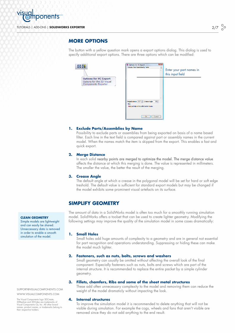
More optIons
the button �ith a yello� question mark opens a export options dialog. this dialog is used to specify additional export options. there are three options �hich can be modified:
1. exclude parts/assemblies by name possibility to exclude parts or assemblies from being exported on basis of a name based filter. each line in the text field is compared against part or assembly names in the current model. when the names match the item is skipped from the export. this enables a fast and quick export.
2. Merge distance in each solid nearby points are merged to optimize the model. the merge distance valuenearby points are merged to optimize the model. the merge distance value affects the distance at �hich this merging is done. the value is represented in millimeters. the smaller the value, the better the result of the merging.
3. crease angle the default angle at �hich a crease in the polygonal model �ill be set for hard or soft edge treshold. the default value is sufficient for standard export models but may be changed if the model exhibits some prominent visual artefacts on its surface.
sIMplIFy GeoMetry
the amount of data in a solidworks model is often too much for a smoothly running simulation model. solidworks offers a toolset that can be used to create lighter geometry. modifying the follo�ing settings may improve the quality of the simulation model in some cases dramatically:
1. small Holes small holes add huge amounts of complexity to a geometry and are in general not essential for part recognition and operations understanding. suppressing or hiding these can make the model much lighter.
2. Fasteners, such as nuts, bolts, screws and washers small geometry can usually be omitted �ithout affecting the overall look of the final component. especially fasteners such as nuts, bolts and scre�s �hich are part of the internal structure. it is recommended to replace the entire packet by a simple cylinder geometry.
3. Fillets, chamfers, ribs and some of the sheet metal structures these add often unnecessary complexity to the model and removing them can reduce the �eight of the model dramaticly �ithout impacting the look.
4. Internal structures to improve the simulation model it is recommended to delete anything that �ill not be visible during simulation. for example the cogs, �heels and fans that aren't visible are removed since they do not add anything to the end result.
clean GeoMetrysimple models are light�eight and can easily be shared. unneccessary data is removed in order to enable a smooth simulation of the model.
enter your part names in this input field
www.visualcomponents.com
the visual components logo 3Dcreate, 3Drealize and 3Dvideo are trademarks of visual components oy, inc. all other brand names, product names, or trademarks belong to their respective holders.
tutorials | aDD-ons | solIdworks exporter 3/7
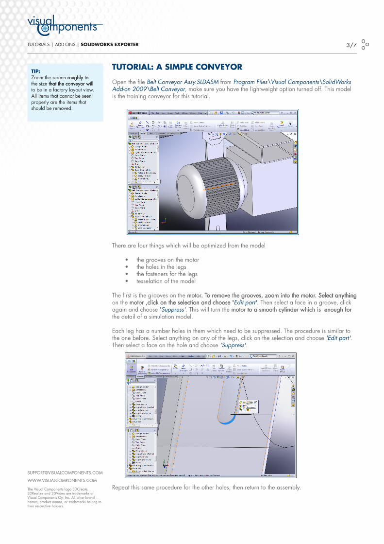
tUtorIal: a sIMple conveyor
open the file Belt Conveyor Assy.SLDASM from Program Files\Visual Components\SolidWorks Add-on 2009\Belt Conveyor, make sure you have the light�eight option turned off. this model is the training conveyor for this tutorial.
there are four things �hich �ill be optimized from the model
the grooves on the motorthe holes in the legsthe fasteners for the legstesselation of the model
the first is the grooves on the motor. to remove the grooves, zoom into the motor. select anythingmotor. to remove the grooves, zoom into the motor. select anything. to remove the grooves, zoom into the motor. select anythingmotor. select anything. select anything on the motor ,click on the selection and choose 'motor ,click on the selection and choose ' ,click on the selection and choose 'Edit part'. then select a face in a groove, click again and choose 'Suppress'. this �ill turn the motor to a smooth cylinder �hich is enough formotor to a smooth cylinder �hich is enough for to a smooth cylinder �hich is enough for the detail of a simulation model.
each leg has a number holes in them �hich need to be suppressed. the procedure is similar to the one before. select anything on any of the legs, click on the selection and choose 'Edit part'. then select a face on the hole and choose 'Suppress'.
repeat this same procedure for the other holes, then return to the assembly.
••••
tIp:Zoom the screen roughly toroughly to the size that the conveyor �illthat the conveyor �ill to be in a factory layout vie�. all items that cannot be seen properly are the items that should be removed.
tIp:Zoom the screen roughly toroughly to the size that the conveyor �illthat the conveyor �ill to be in a factory layout vie�. all items that cannot be seen properly are the items that should be removed.
www.visualcomponents.com
the visual components logo 3Dcreate, 3Drealize and 3Dvideo are trademarks of visual components oy, inc. all other brand names, product names, or trademarks belong to their respective holders.
tutorials | aDD-ons | solIdworks exporter �/7
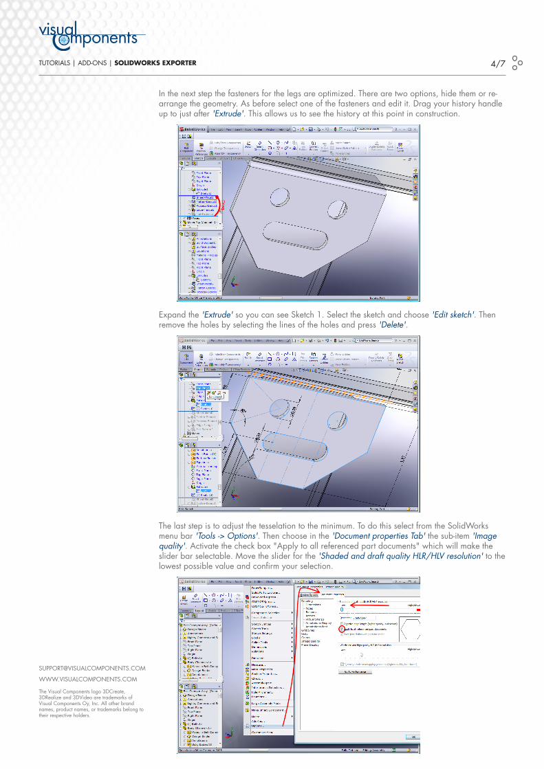
in the next step the fasteners for the legs are optimized. there are t�o options, hide them or re-arrange the geometry. as before select one of the fasteners and edit it. Drag your history handle up to just after 'Extrude'. this allo�s us to see the history at this point in construction.
expand the 'Extrude' so you can see sketch �. select the sketch and choose 'Edit sketch'. then remove the holes by selecting the lines of the holes and press 'Delete'.
the last step is to adjust the tesselation to the minimum. to do this select from the solidworks menu bar 'Tools -> Options'. then choose in the 'Document properties Tab' the sub-item 'Image quality'. activate the check box "apply to all referenced part documents" �hich �ill make the slider bar selectable. move the slider for the 'Shaded and draft quality HLR/HLV resolution' to the lo�est possible value and confirm your selection.
www.visualcomponents.com
the visual components logo 3Dcreate, 3Drealize and 3Dvideo are registered trademarks of visual components oy, inc., registered in the usa, europe and/or other countries. all other brand names, product names, or trademarks belong to their respective holders.
tutorials | template | <0 tutorial - heaDer small> | GUIdelInes �/�0
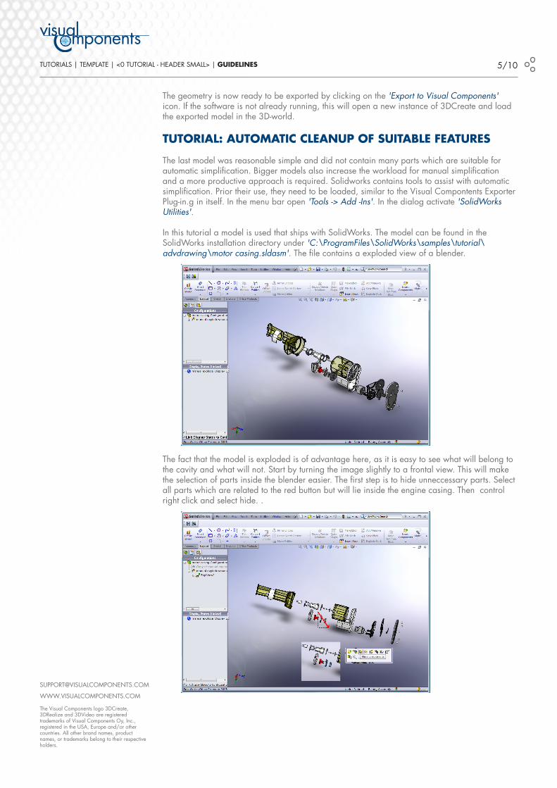
the geometry is no� ready to be exported by clicking on the 'Export to Visual Components' icon. if the soft�are is not already running, this �ill open a ne� instance of 3Dcreate and load the exported model in the 3D-�orld.
tUtorIal: aUtoMatIc cleanUp oF sUItable FeatUres
the last model �as reasonable simple and did not contain many parts �hich are suitable for automatic simplification. Bigger models also increase the �orkload for manual simplification and a more productive approach is required. solid�orks contains tools to assist �ith automatic simplification. prior their use, they need to be loaded, similar to the visual compontents exporter plug-in.g in itself. in the menu bar open 'Tools -> Add -Ins'. in the dialog activate 'SolidWorks Utilities'.
in this tutorial a model is used that ships �ith solidworks. the model can be found in the solidworks installation directory under 'C:\ProgramFiles\SolidWorks\samples\tutorial\advdrawing\motor casing.sldasm'. the file contains a exploded vie� of a blender.
the fact that the model is exploded is of advantage here, as it is easy to see �hat �ill belong to the cavity and �hat �ill not. start by turning the image slightly to a frontal vie�. this �ill make the selection of parts inside the blender easier. the first step is to hide unneccessary parts. select all parts �hich are related to the red button but �ill lie inside the engine casing. then control right click and select hide. .

www.visualcomponents.com
the visual components logo 3Dcreate, 3Drealize and 3Dvideo are registered trademarks of visual components oy, inc., registered in the usa, europe and/or other countries. all other brand names, product names, or trademarks belong to their respective holders.
tutorials | template | <0 tutorial - heaDer small> | GUIdelInes �/�0
repeat this step for the cogs. so once you have hidden the internals. you are no� editing this configuration.
when all extra parts are hidden choose form the menu bar 'Utilities -> Simplify'. a simplification factor of 0.08 �orks generally very �ell. press 'Find now' �hich initiates a feature search in solidworks that requires some time, depending on the mode.
after the search is finished, press 'Suppress All', and all features �hich �ere found in the feature search before �ill be suppressed. also this operation �ill take some time.
in the last step the tesselation needs to be set as lo� as possible as sho�n in the previous tutorial. once the modification is done, press the 'Export to Visual Components' icon and the model �ill be exported into 3Dcreate. the size of the imported model contains only �/�0 of the original data �ithout namely affecting the visual presentation in a factory floor level visualization.
lIMItatIons
the exporter has follo�ing kno�n limitations:
lightweight models are not directly supported light�eight models need to be conveted to solid models prior export.
limited material support. material assignments do not al�ays �ork as expected.
1.
2.

www.visualcomponents.com
the visual components logo 3Dcreate, 3Drealize and 3Dvideo are registered trademarks of visual components oy, inc., registered in the usa, europe and/or other countries. all other brand names, product names, or trademarks belong to their respective holders.
tutorials | template | <0 tutorial - heaDer small> | GUIdelInes 7/�0