Embed Size (px)
Citation preview
SolidWorks: Extruded Cuts,
Fillets, and PatternsFillets, and Patterns
Introduction to Robotics
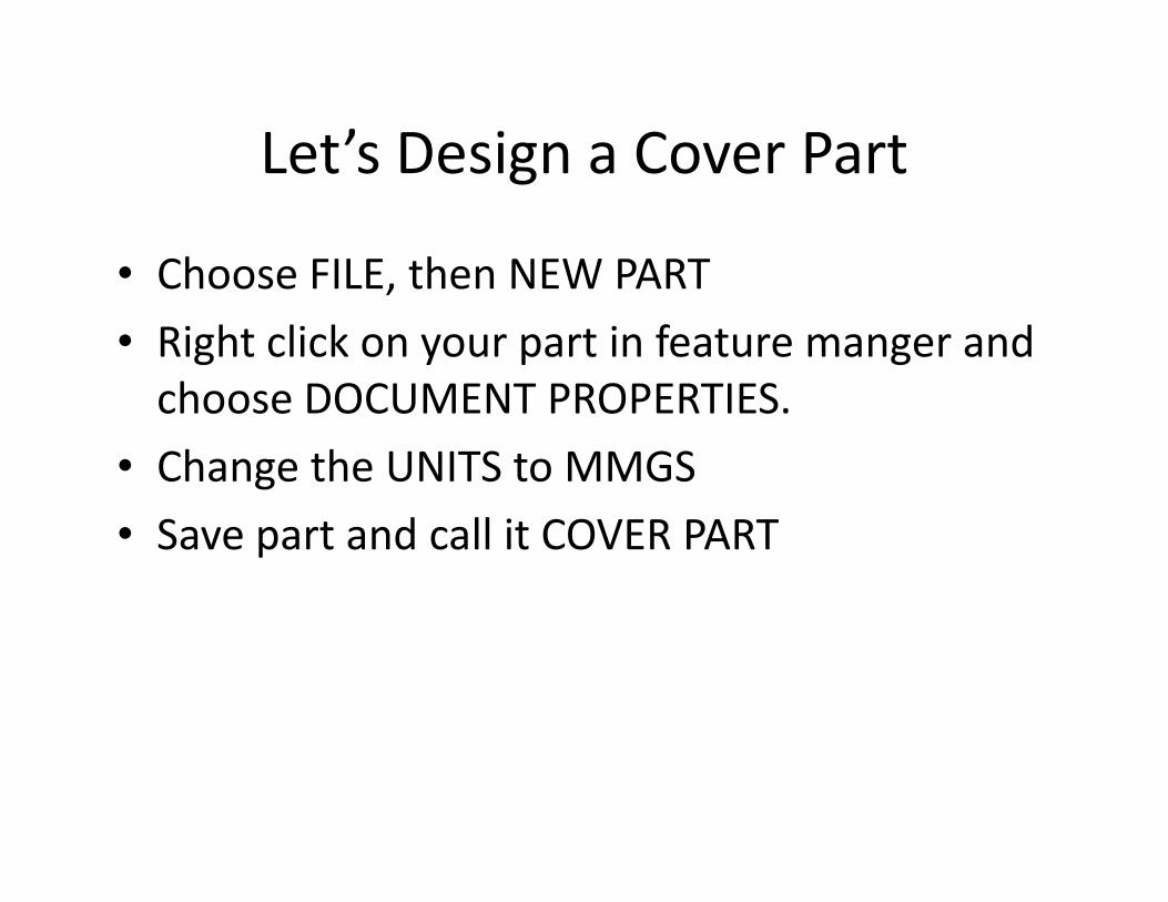
Let’s Design a Cover Part
• Choose FILE, then NEW PART
• Right click on your part in feature manger and
choose DOCUMENT PROPERTIES.
• Change the UNITS to MMGS• Change the UNITS to MMGS
• Save part and call it COVER PART
Cover Part
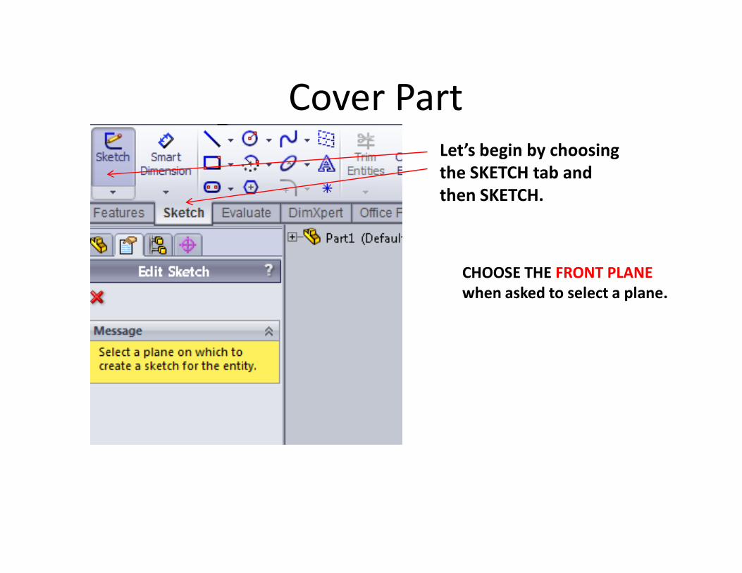
Let’s begin by choosing
the SKETCH tab and
then SKETCH.
CHOOSE THE FRONT PLANE
when asked to select a plane.when asked to select a plane.

Cover
Using the rectangle option make a corner rectangle with
the lower horizontal line touching the origin.
Using the CTRL key, select the MIDPOINT of the line and
the origin and add a COINCIDENT RELATION.
Cover Part
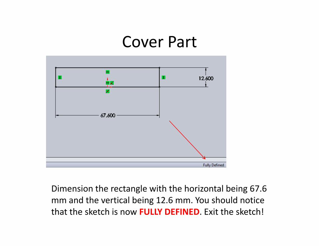
Dimension the rectangle with the horizontal being 67.6
mm and the vertical being 12.6 mm. You should notice
that the sketch is now FULLY DEFINED. Exit the sketch!
Cover Part
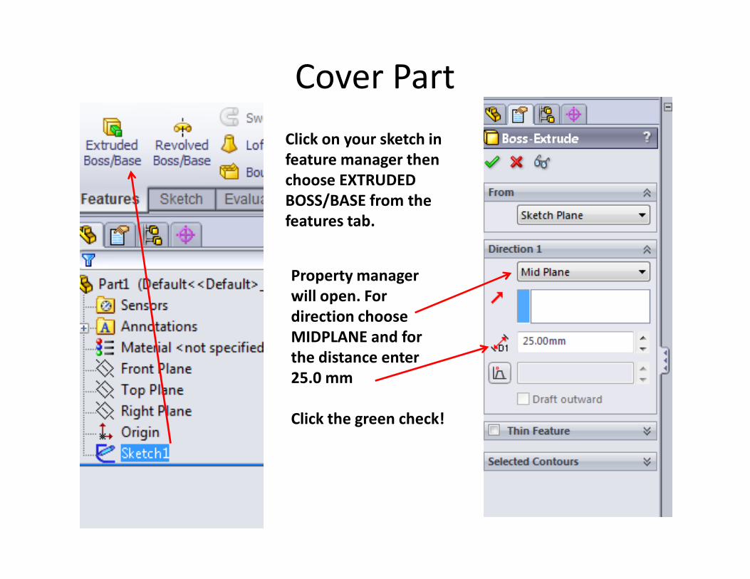
Click on your sketch in
feature manager then
choose EXTRUDED
BOSS/BASE from the
features tab.
Property manager
will open. For will open. For
direction choose
MIDPLANE and for
the distance enter
25.0 mm
Click the green check!
Cover Part
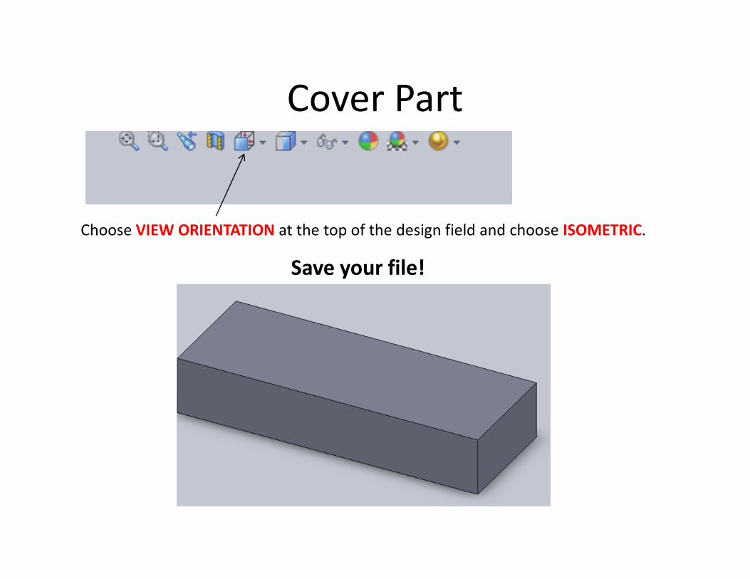
Choose VIEW ORIENTATION at the top of the design field and choose ISOMETRIC.
Save your file!
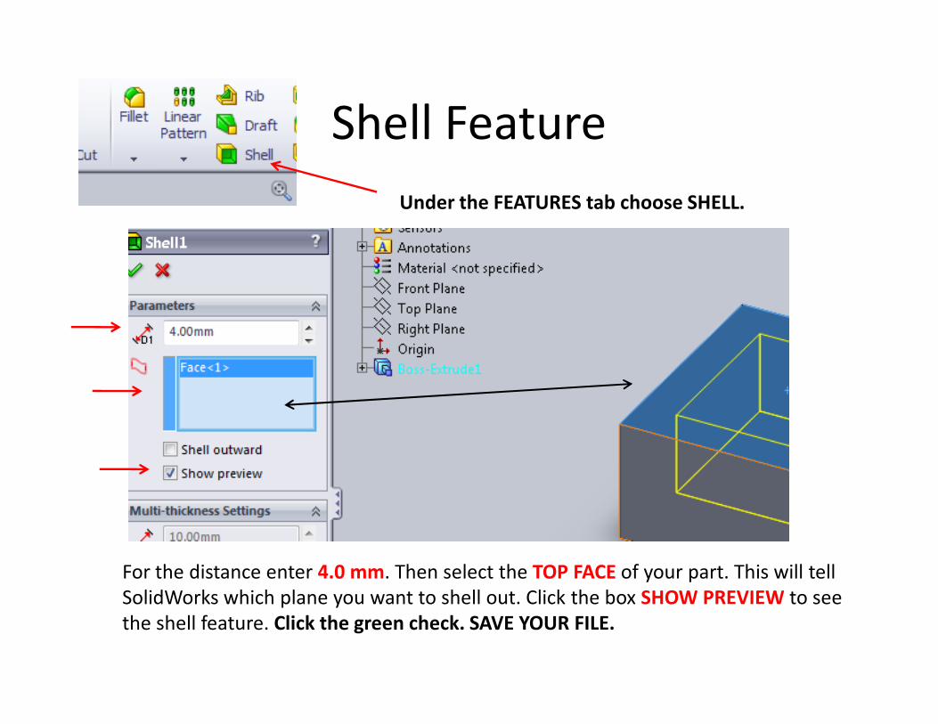
Shell Feature
Under the FEATURES tab choose SHELL.
For the distance enter 4.0 mm. Then select the TOP FACE of your part. This will tell
SolidWorks which plane you want to shell out. Click the box SHOW PREVIEW to see
the shell feature. Click the green check. SAVE YOUR FILE.
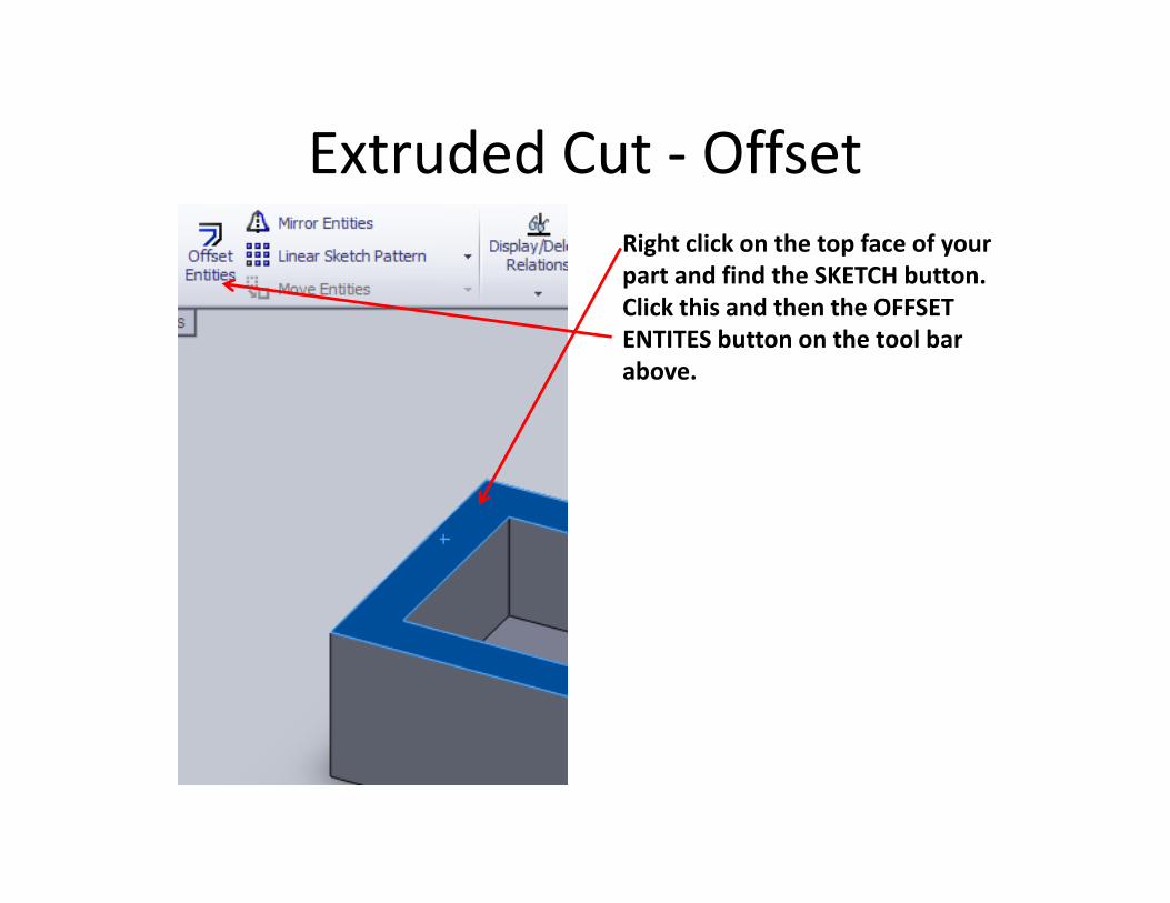
Extruded Cut - Offset
Right click on the top face of your
part and find the SKETCH button.
Click this and then the OFFSET
ENTITES button on the tool bar
above.
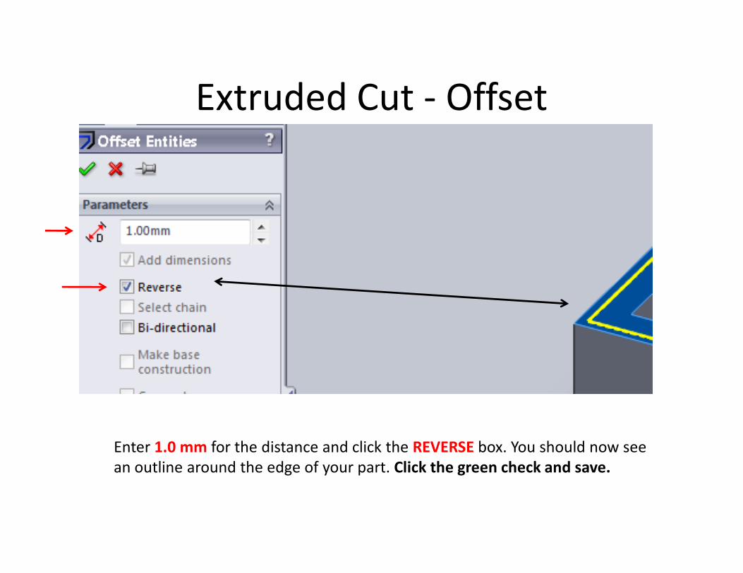
Extruded Cut - Offset
Enter 1.0 mm for the distance and click the REVERSE box. You should now see
an outline around the edge of your part. Click the green check and save.
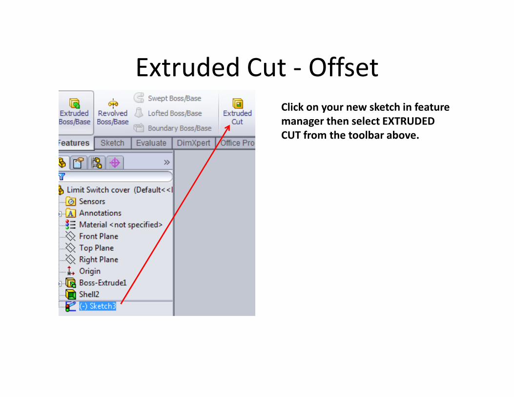
Extruded Cut - Offset
Click on your new sketch in feature
manager then select EXTRUDED
CUT from the toolbar above.
Extruded Cut - Offset
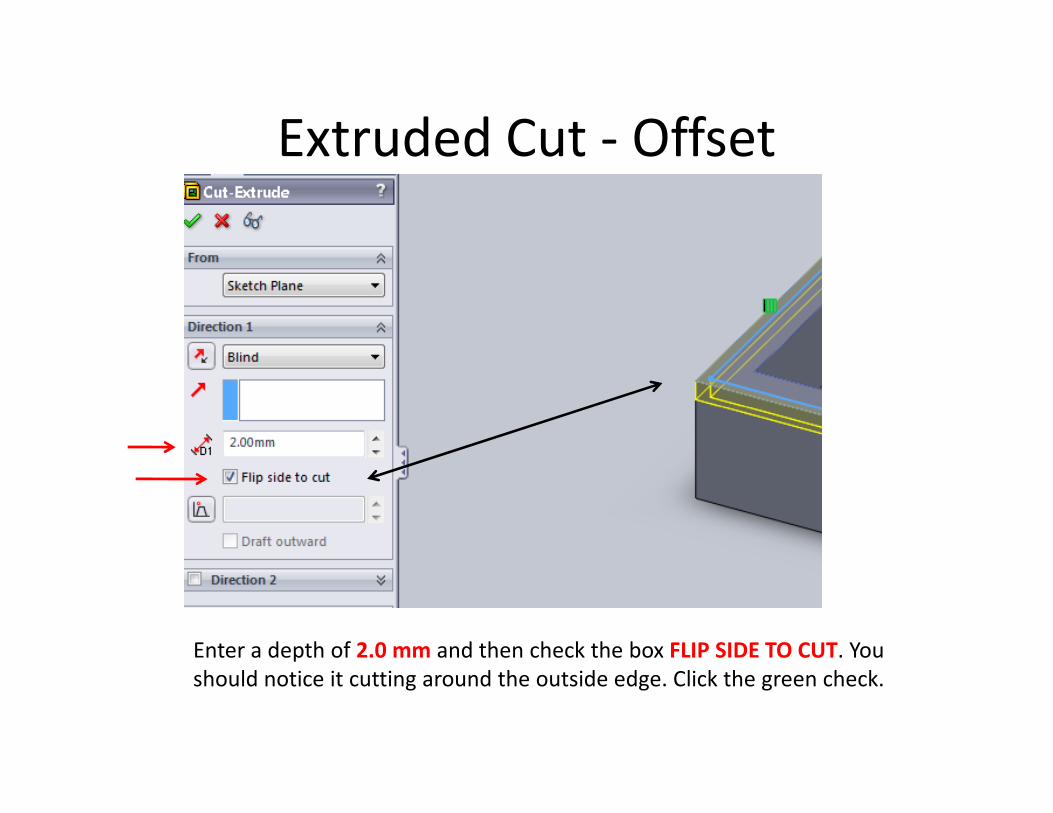
Enter a depth of 2.0 mm and then check the box FLIP SIDE TO CUT. You
should notice it cutting around the outside edge. Click the green check.

Making a circular holeChoose the VIEW ORIENTATION button on the
design plane above your part and select the
TOP VIEW.
Select SKETCH from the Sketch tab and select the top plane of your part.
Select the CIRCLE button
then draw a circle on
the bottom left corner
as shown. You must
click and hold to make
the circle.
Making a circular hole
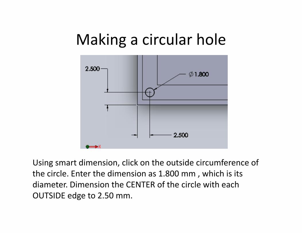
Using smart dimension, click on the outside circumference of
the circle. Enter the dimension as 1.800 mm , which is its
diameter. Dimension the CENTER of the circle with each
OUTSIDE edge to 2.50 mm.

Making a circular holeSwitch your orientation to isometric.
Make sure your sketch is highlighted
in feature manager and select
EXTRUDED CUT from the toolbar.
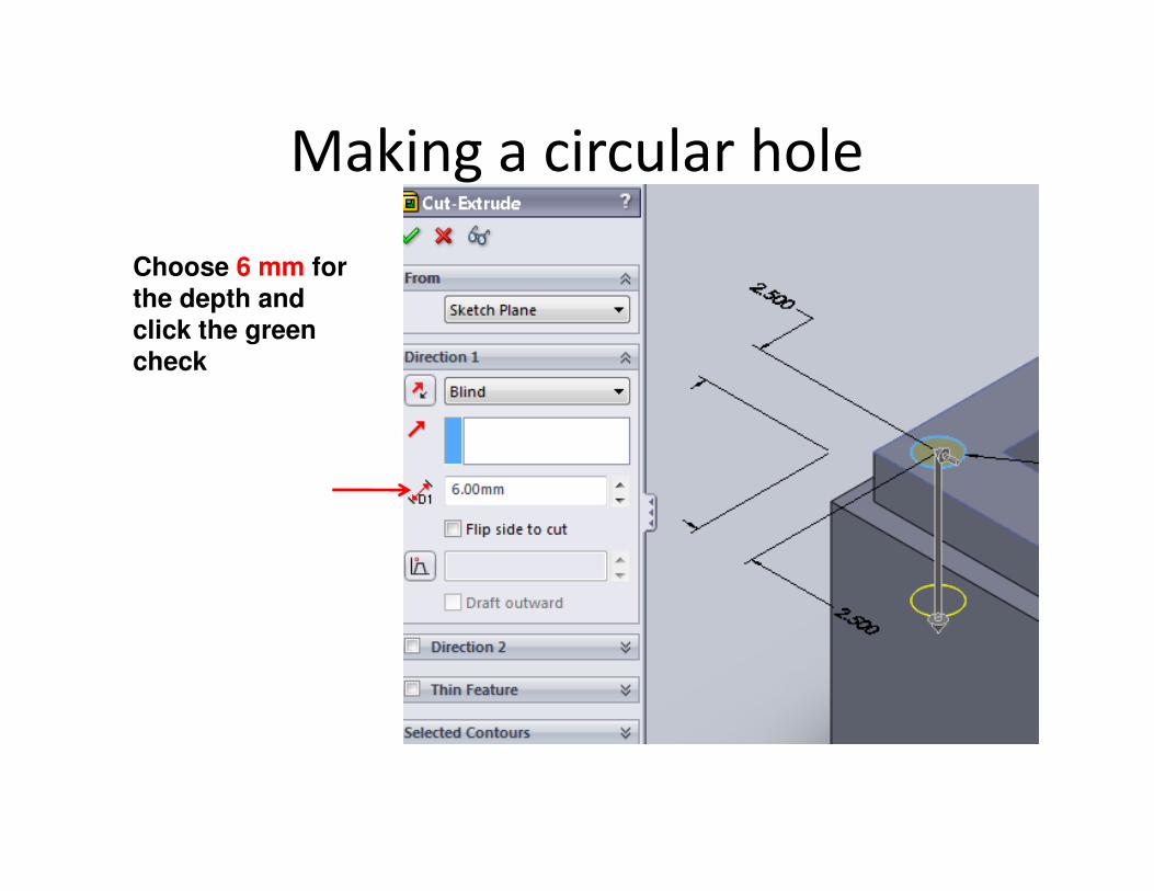
Making a circular hole
Choose 6 mm for the depth and
click the green
check
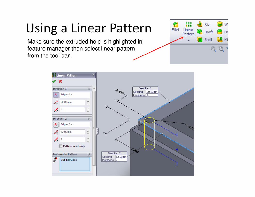
Using a Linear PatternMake sure the extruded hole is highlighted in
feature manager then select linear pattern
from the tool bar.
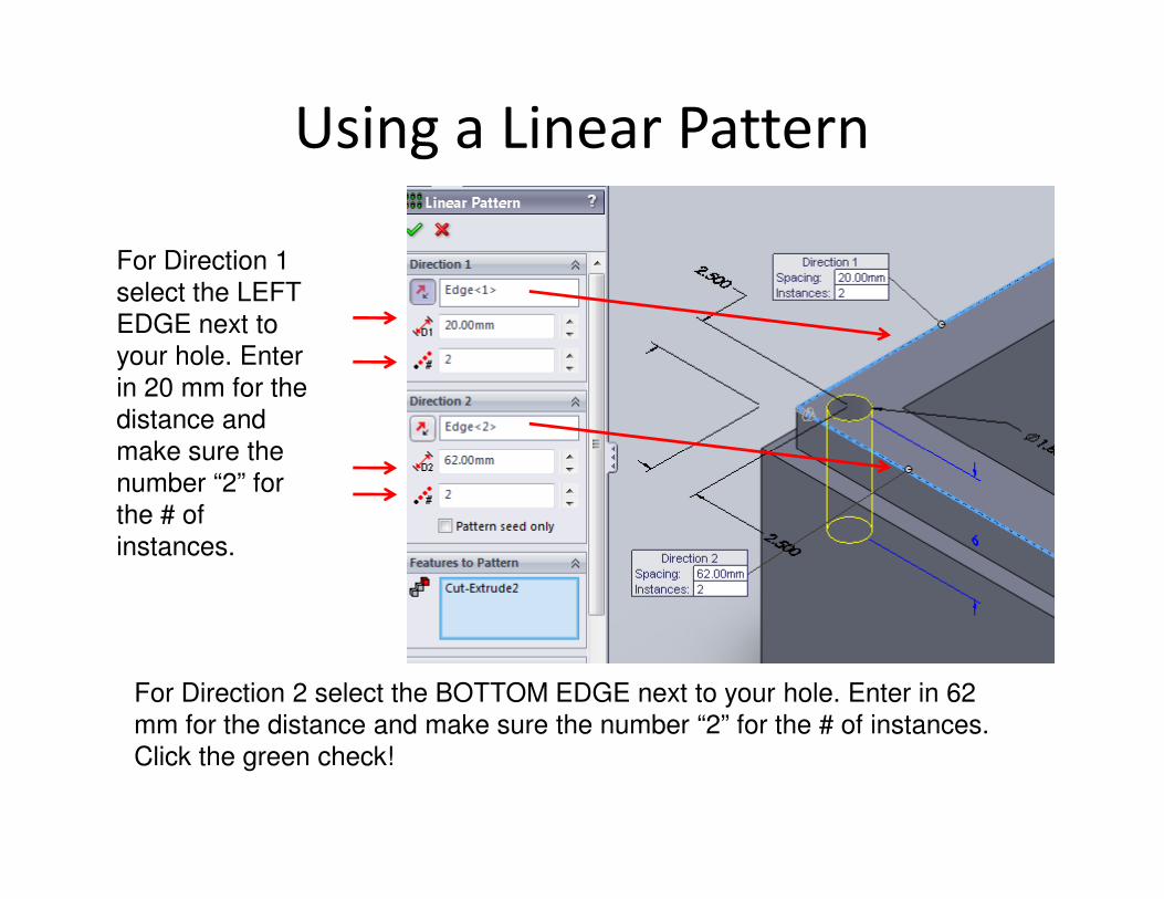
Using a Linear Pattern
For Direction 1
select the LEFT
EDGE next to
your hole. Enter
in 20 mm for the
distance and
make sure the make sure the
number “2” for
the # of
instances.
For Direction 2 select the BOTTOM EDGE next to your hole. Enter in 62
mm for the distance and make sure the number “2” for the # of instances.
Click the green check!
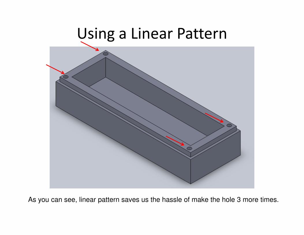
Using a Linear Pattern
As you can see, linear pattern saves us the hassle of make the hole 3 more times.

FilletsChoose FILLET from the toolbar.
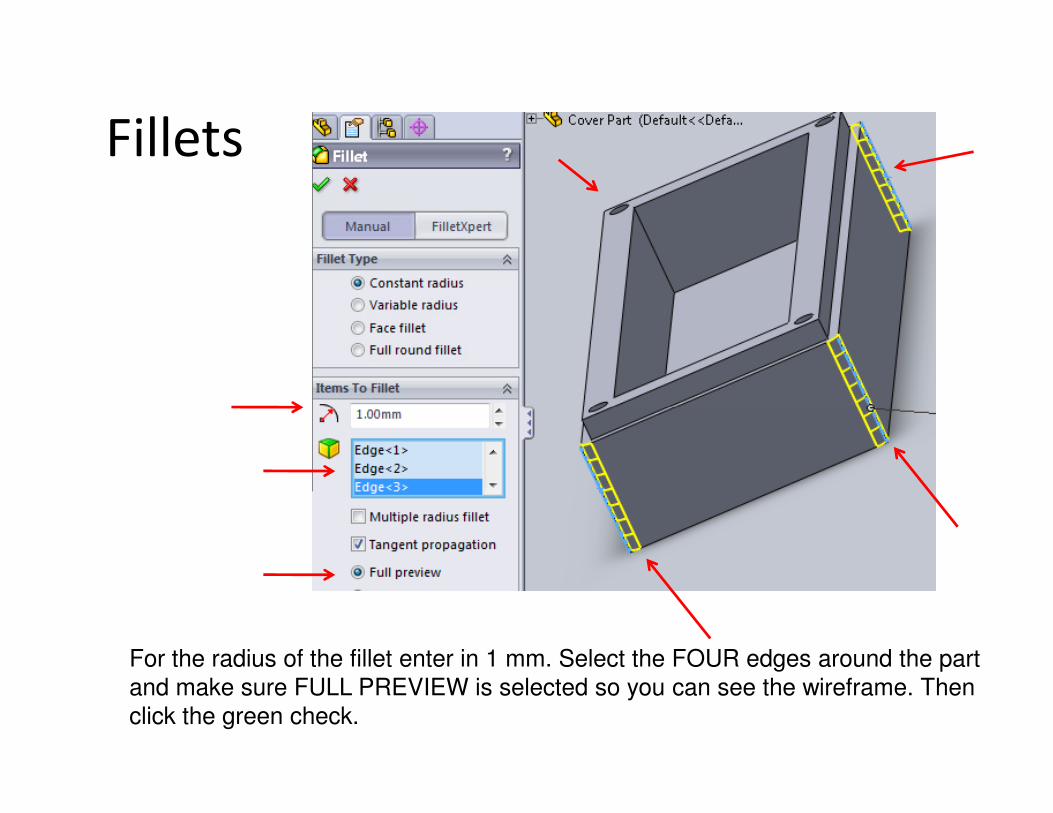
Fillets
For the radius of the fillet enter in 1 mm. Select the FOUR edges around the part
and make sure FULL PREVIEW is selected so you can see the wireframe. Then
click the green check.
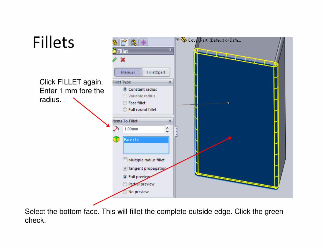
Fillets
Click FILLET again.
Enter 1 mm fore the
radius.
Select the bottom face. This will fillet the complete outside edge. Click the green
check.
Cover Switch Drawing
Make a SolidWorks drawing for the cover part. Make sure each view, except isometric, has dimensions. Print this drawing out. Write your name in the title block and turn it in.