Embed Size (px)
Citation preview

4
62 Industrial Hydraulics
Sollwerttechnik und SignalwandlerSetpoint technology and signal transducersTechnique consigne et convertisseur de signaux
1 2
6 9 !¡
7
3 4 5 8 !≠

4
Industrial Hydraulics 63
BestellübersichtOrdering rangeGamme de commande
Typ Benennung SeiteType Description PageType Désignation UBY ... Page «
1 Sollwertgeber 013/45 64 0 811 405 121Setpoint generatorGénérateur de consigne
2 POTM-M Potentiometer 013/36 66 B 830 303 560PotentiometerPotentiomètre
3 POTM-CARD Sollwertabrufkarte 013/77 68 0 811 405 093Setpoint signal cardCarte d’appel des signaux de consigne
4 RAMP-POTM Sollwert- und Rampenkarte 013/80 72 0 811 405 094Setpoint signal and ramp cardCarte de signaux de consigne et de rampes
5 RAMP-LIN Sollwert- und Rampenbildner 013/79 78 0 811 405 116Setpoint and ramp generatorGénérateur de consignes avec rampes
6 POTM-RAMP Sollwert- und Rampenmodul 013/112 85 0 811 405 108Setpoint and ramp moduleModule de signaux de consigne et de rampes
7 DRM2 Digitales Rampenmodul 013/106 88 B 830 303 581Digital ramp moduleRampe numérique modulaire
8 I/U2-U/I1 Strom/Spannungs-Signalwandler 013/81 96 B 830 303 440Current/voltage signal transducerConvertisseur de signaux courant/tension
9 I/U-mA/V Strom/Spannungs-Signalwandler 013/108 100 0 811 405 105Current/voltage signal transducerConvertisseur de signaux courant/tension
!≠ D/A2-BCD Digital/Analog-Wandler 013/78 103 B 830 303 439Digital/analog converterConvertisseur numérique/analogique
!¡ SIGN-ADAP Signalanpassungs-Modul 013/113 108 0 811 405 107Signal adjustment moduleModule adaptation du signal
4
64 Industrial Hydraulics
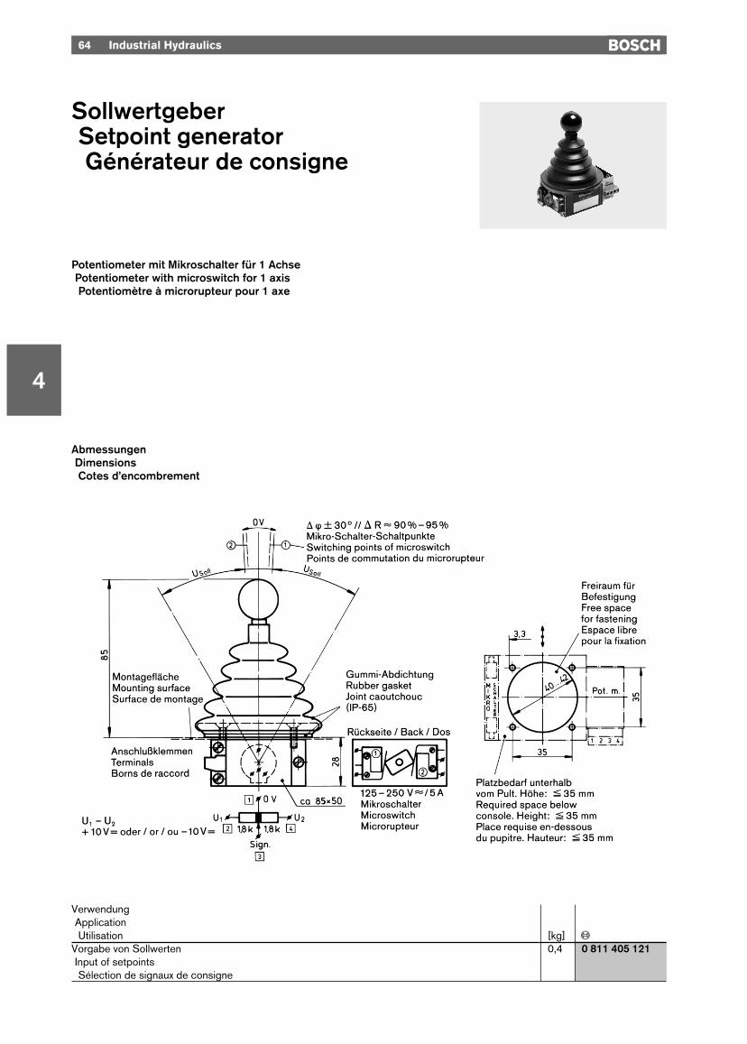
SollwertgeberSetpoint generatorGénérateur de consigne
Potentiometer mit Mikroschalter für 1 AchsePotentiometer with microswitch for 1 axisPotentiomètre à microrupteur pour 1 axe
VerwendungApplicationUtilisation [kg] «
Vorgabe von Sollwerten 0,4 0 811 405 121Input of setpointsSélection de signaux de consigne
AbmessungenDimensionsCotes d’encombrement
Industrial Hydraulics 65
4
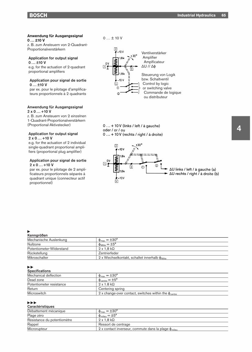
Anwendung für Ausgangssignal0 . . . ±10 Vz. B. zum Ansteuern von 2-Quadrant-Proportionalverstärkern
Application for output signal0 . . . ±10 Ve.g. for the actuation of 2-quadrantproportional amplifiers
Application pour signal de sortie0 . . . ±10 Vpar ex. pour le pilotage d’amplifica-teurs proportionnels à 2 quadrants
Anwendung für Ausgangssignal 2 x 0 . . . +10 Vz. B. zum Ansteuern von 2 einzelnen1-Quadrant-Proportionalverstärkern(Proportional-Aktivstecker)
Application for output signal2 x 0 . . . +10 Ve.g. for the actuation of 2 individualsingle-quadrant proportional ampli-fiers (proportional plug amplifier)
Application pour signal de sortie2 x 0 . . . +10 Vpar ex. pour le pilotage de 2 ampli-ficateurs proportionnels séparés àquadrant unique (connecteur actifproportionnel)
yKenngrößenMechanische Auslenkung ϕmax. = ±30°Nullzone ϕMitte = ±5°Potentiometer-Widerstand 2 x 1,8 kΩRückstellung ZentrierfederMikroschalter 2 x Wechselkontakt, schaltet innerhalb ϕMitte
yySpecificationsMechanical deflection ϕmax. = ±30°Dead zone ϕcentre = ±5°Potentiometer resistance 2 x 1.8 kΩReturn Centering springMicroswitch 2 x change-over contact, switches within the ϕcentre
yyyCaractéristiquesDébattement mécanique ϕmax. = ±30°Plage zéro ϕmilieu = ±5°Résistance du potentiomètre 2 x 1,8 kΩRappel Ressort de centrageMicrorupteur 2 x contact inverseur, commute dans la plage ϕmilieu
VentilverstärkerAmplifierAmplficateur
∆U // ∆ϕ
Steuerung von Logikbzw. SchaltventilControl by logicor switching valveCommande de logiqueou distributeur
0 … ± 10 V
4
66 Industrial Hydraulics
PotentiometerPotentiometerPotentiomètre
AbmessungenDimensionsCotes d’encombrement
Typ VerwendungType ApplicationType Utilisation [kg] «
POTM-M Sollwertvorgabe 0,1 B 830 303 560Setpoint inputSélection de signaux de consigne
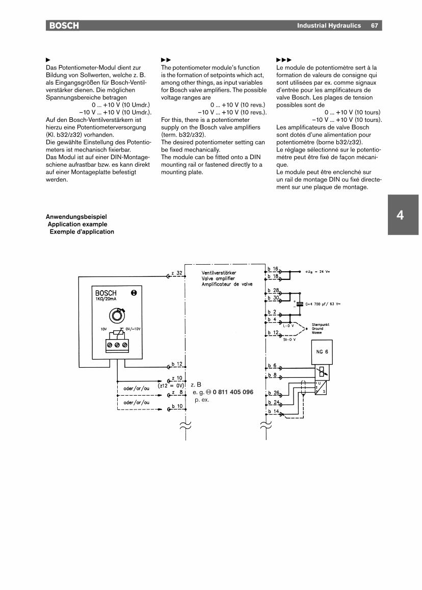
yDas Potentiometer-Modul dient zurBildung von Sollwerten, welche z. B.als Eingangsgrößen für Bosch-Ventil-verstärker dienen. Die möglichenSpannungsbereiche betragen
0 ... +10 V (10 Umdr.).–10 V ... +10 V (10 Umdr.).
Auf den Bosch-Ventilverstärkern isthierzu eine Potentiometerversorgung(Kl. b32/z32) vorhanden.Die gewählte Einstellung des Potentio-meters ist mechanisch fixierbar. Das Modul ist auf einer DIN-Montage-schiene aufrastbar bzw. es kann direktauf einer Montageplatte befestigtwerden.
yyThe potentiometer module’s function is the formation of setpoints which act,among other things, as input variablesfor Bosch valve amplifiers. The possiblevoltage ranges are
0 ... +10 V (10 revs.).–10 V ... +10 V (10 revs.).
For this, there is a potentiometersupply on the Bosch valve amplifiers(term. b32/z32).The desired potentiometer setting canbe fixed mechanically.The module can be fitted onto a DINmounting rail or fastened directly to amounting plate.
yyyLe module de potentiomètre sert à laformation de valeurs de consigne quisont utilisées par ex. comme signauxd’entrée pour les amplificateurs devalve Bosch. Les plages de tensionpossibles sont de
0 ... +10 V (10 tours).–10 V ... +10 V (10 tours).
Les amplificateurs de valve Boschsont dotés d’une alimentation pourpotentiomètre (borne b32/z32).Le réglage sélectionné sur le potentio-métre peut être fixé de façon mécani-que.Le module peut être enclenché sur un rail de montage DIN ou fixé directe-ment sur une plaque de montage.
Industrial Hydraulics 67
4AnwendungsbeispielApplication exampleExemple d’application
z. Be. g. « 0 811 405 096p. ex.

4
68 Industrial Hydraulics
SollwertabrufkarteSetpoint signal cardCarte d’appel des signaux de consigne
FrontplatteFront platePlaque frontale
Typ VerwendungType ApplicationType Utilisation [kg] «
POTM-CARD Abruf von Sollwerten ohne Rampen 0,3 0 811 405 093Recall of setpoints without rampsAppel de signaux de consigne sans rampes
Industrial Hydraulics 69
4
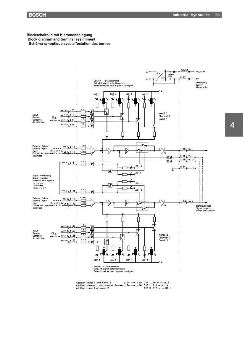
Blockschaltbild mit KlemmenbelegungBlock diagram and terminal assignmentSchéma synoptique avec affectation des bornes
70 Industrial Hydraulics
4
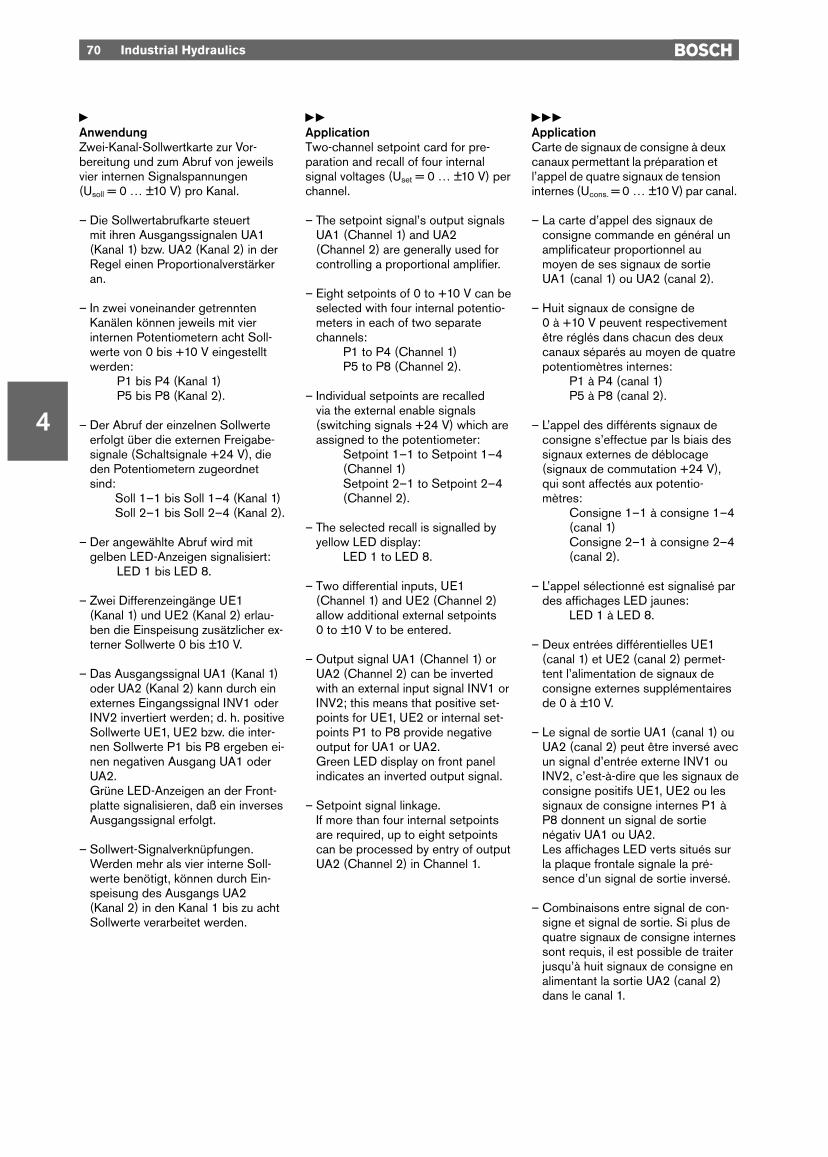
yAnwendungZwei-Kanal-Sollwertkarte zur Vor-bereitung und zum Abruf von jeweilsvier internen Signalspannungen (Usoll = 0 … ±10 V) pro Kanal.
– Die Sollwertabrufkarte steuert mit ihren Ausgangssignalen UA1 (Kanal 1) bzw. UA2 (Kanal 2) in derRegel einen Proportionalverstärkeran.
– In zwei voneinander getrenntenKanälen können jeweils mit vierinternen Potentiometern acht Soll-werte von 0 bis +10 V eingestelltwerden:
P1 bis P4 (Kanal 1)P5 bis P8 (Kanal 2).
– Der Abruf der einzelnen Sollwerteerfolgt über die externen Freigabe-signale (Schaltsignale +24 V), dieden Potentiometern zugeordnetsind:
Soll 1–1 bis Soll 1–4 (Kanal 1)Soll 2–1 bis Soll 2–4 (Kanal 2).
– Der angewählte Abruf wird mitgelben LED-Anzeigen signalisiert:
LED 1 bis LED 8.
– Zwei Differenzeingänge UE1(Kanal 1) und UE2 (Kanal 2) erlau-ben die Einspeisung zusätzlicher ex-terner Sollwerte 0 bis ±10 V.
– Das Ausgangssignal UA1 (Kanal 1)oder UA2 (Kanal 2) kann durch einexternes Eingangssignal INV1 oderINV2 invertiert werden; d. h. positiveSollwerte UE1, UE2 bzw. die inter-nen Sollwerte P1 bis P8 ergeben ei-nen negativen Ausgang UA1 oderUA2.Grüne LED-Anzeigen an der Front-platte signalisieren, daß ein inversesAusgangssignal erfolgt.
– Sollwert-Signalverknüpfungen.Werden mehr als vier interne Soll-werte benötigt, können durch Ein-speisung des Ausgangs UA2 (Kanal 2) in den Kanal 1 bis zu achtSollwerte verarbeitet werden.
yyApplicationTwo-channel setpoint card for pre-paration and recall of four internalsignal voltages (Uset = 0 … ±10 V) perchannel.
– The setpoint signal’s output signalsUA1 (Channel 1) and UA2 (Channel 2) are generally used forcontrolling a proportional amplifier.
– Eight setpoints of 0 to +10 V can beselected with four internal potentio-meters in each of two separatechannels:
P1 to P4 (Channel 1)P5 to P8 (Channel 2).
– Individual setpoints are recalled via the external enable signals(switching signals +24 V) which areassigned to the potentiometer:
Setpoint 1–1 to Setpoint 1–4(Channel 1)Setpoint 2–1 to Setpoint 2–4(Channel 2).
– The selected recall is signalled byyellow LED display:
LED 1 to LED 8.
– Two differential inputs, UE1 (Channel 1) and UE2 (Channel 2)allow additional external setpoints 0 to ±10 V to be entered.
– Output signal UA1 (Channel 1) orUA2 (Channel 2) can be invertedwith an external input signal INV1 orINV2; this means that positive set-points for UE1, UE2 or internal set-points P1 to P8 provide negativeoutput for UA1 or UA2.Green LED display on front panelindicates an inverted output signal.
– Setpoint signal linkage.If more than four internal setpointsare required, up to eight setpointscan be processed by entry of outputUA2 (Channel 2) in Channel 1.
yyyApplicationCarte de signaux de consigne à deuxcanaux permettant la préparation etl’appel de quatre signaux de tensioninternes (Ucons. = 0 … ±10 V) par canal.
– La carte d’appel des signaux deconsigne commande en général unamplificateur proportionnel aumoyen de ses signaux de sortieUA1 (canal 1) ou UA2 (canal 2).
– Huit signaux de consigne de 0 à +10 V peuvent respectivementêtre réglés dans chacun des deuxcanaux séparés au moyen de quatrepotentiomètres internes:
P1 à P4 (canal 1)P5 à P8 (canal 2).
– L’appel des différents signaux deconsigne s’effectue par ls biais dessignaux externes de déblocage(signaux de commutation +24 V),qui sont affectés aux potentio-mètres:
Consigne 1–1 à consigne 1–4(canal 1)Consigne 2–1 à consigne 2–4(canal 2).
– L’appel sélectionné est signalisé pardes affichages LED jaunes:
LED 1 à LED 8.
– Deux entrées différentielles UE1(canal 1) et UE2 (canal 2) permet-tent l’alimentation de signaux deconsigne externes supplémentairesde 0 à ±10 V.
– Le signal de sortie UA1 (canal 1) ouUA2 (canal 2) peut être inversé avecun signal d’entrée externe INV1 ouINV2, c’est-à-dire que les signaux deconsigne positifs UE1, UE2 ou lessignaux de consigne internes P1 àP8 donnent un signal de sortienégativ UA1 ou UA2.Les affichages LED verts situés surla plaque frontale signale la pré-sence d’un signal de sortie inversé.
– Combinaisons entre signal de con-signe et signal de sortie. Si plus dequatre signaux de consigne internessont requis, il est possible de traiterjusqu’à huit signaux de consigne enalimentant la sortie UA2 (canal 2)dans le canal 1.

Industrial Hydraulics 71
4
yKenngrößenFormat der Leiterkarte (100 x 160 x ca. 35) mm (B x L x H), Europaformat mit Frontplatte 7 TESteckverbindung Stecker DIN 41 612-F32Umgebungstemperatur 0 °C ... +70 °C, Lagertemperatur min. –20 °C, max. +70 °CVersorgungsspannung nominal 24 V=, 21 ... 28 V ungesiebtUB an z2–b2 (gleichgerichtete Wechselspannung)Stromaufnahme max. 150 mASignal-Vorbereitung 8 Trimm-Potis für 0 ... 10 V
Negative Ausgangssignale durch externen Befehl INV1 (b8)bzw. INV2 (b26)
Signalabruf 8 Signaleingänge +24 V (max. 40 V=) Ri = 2 kΩz2 ... z8/z26 ... z32 P1 ... P4 bzw. P5 ... P8 einzeln oder summierendAnzeige LED gelb für jeweils abgerufenen Potentiometer
LED grün für wahres Ausgangssignal und für invertiertes AusgangssignalZusammenfassung Brücke z24–z18: P1 ... P4 +P5 ... P8P1 ... P8 über Kanal 1 Brücke z24–z16: P1 ... P4 –P5 ... P8
yySpecificationsPCB Format (100 x 160 x approx. 35) mm (W x L x H), Europe format with front plate
(7 modular spacings)Plug connection Plug to DIN 41 612-F32 Ambient temperature 0 °C ... +70 °C, storage temperature min. –20 °C, max. +70 °CSupply voltage 24 V DC nominal, 21 ... 28 V non-filteredUB at z2–b2 (rectified alternating current)Current rating Max. 150 mASignal preparation 8 trimming potentiometers for 0 ... 10 V
Negative output signals via external command INV1 (b8) or INV2 (b26)Signal recall 8 signal inputs +24 V (max. 40 V=) Ri = 2 kΩz2 ... z8/z26 ... z32 P1 ... P4 and P5 ... P8 individual or cumulativeDisplay Yellow LED for potentiometer being recalled
Green LED for true output signal and inverted output signalAddition Bridge z24–z18: P1 ... P4 +P5 ... P8P1 ... P8 via channel 1 Bridge z24–z16: P1 ... P4 –P5 ... P8
yyyCaractéristiquesDimension de la carte imprimée (100 x 160 x env. 35) mm (L x L x H), Format Europe avec plaque frontale
(7 unités partielles)Branchement Connecteur DIN 41 612-F32 Température ambiante 0 °C ... +70 °C, température de stockage min. –20 °C, max. +70 °CTension d’alimentation nominal 24 V=, 21 ... 28 V non filtréUB sur z2–b2 (tension alternative redressée)Consommation max. 150 mAPréparation de signaux 8 potentiomètres de 0 ... 10 V
Signaux de sortie négatifs par ordre externe INV1 (b8) ou INV2 (b26)Appel de signaux 8 signaux d’entrée +24 V (max. 40 V=) Ri = 2 kΩz2 ... z8/z26 ... z32 P1 ... P4 ou P5 ... P8 separé ou cumulableAffichage LED jaune pour le potentiomètre de chaque circuit actif
LED verte pour signal de sortie réel et signal de sortie inverséAddition Pont z24–z18: P1 ... P4 +P5 ... P8P1 ... P8 par canal 1 Pont z24–z16: P1 ... P4 –P5 ... P8

4
72 Industrial Hydraulics
Sollwert- und RampenkarteSetpoint signal and ramp cardCarte de signaux de consigneet de rampes
FrontplatteFront platePlaque frontale
Typ VerwendungType ApplicationType Utilisation [kg] «
RAMP-POTM Abruf von Sollwerten mit Rampen 0,2 0 811 405 094Recall of setpoints with rampsAppel de signaux de consigne avec rampes

Industrial Hydraulics 73
4
Blockschaltbild mit KlemmenbelegungBlock diagram and terminal assignmentSchéma synoptique avec affectation des bornes
74 Industrial Hydraulics
4
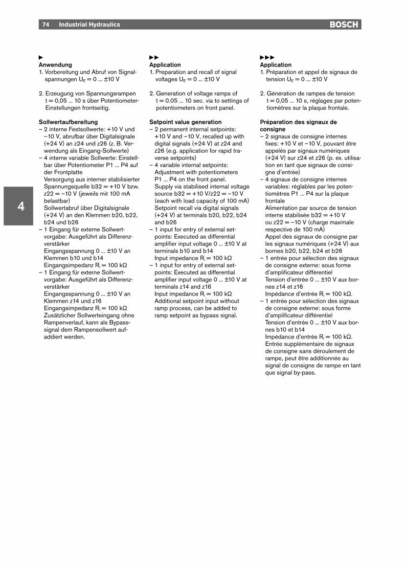
yAnwendung1. Vorbereitung und Abruf von Signal-
spannungen UE = 0 ... ±10 V
2. Erzeugung von Spannungsrampen t = 0,05 ... 10 s über Potentiometer-Einstellungen frontseitig.
Sollwertaufbereitung– 2 interne Festsollwerte: +10 V und
–10 V, abrufbar über Digitalsignale(+24 V) an z24 und z26 (z. B. Ver-wendung als Eingang-Sollwerte)
– 4 interne variable Sollwerte: Einstell-bar über Potentiometer P1 ... P4 aufder FrontplatteVersorgung aus interner stabilisierterSpannungsquelle b32 = +10 V bzw.z22 = –10 V (jeweils mit 100 mAbelastbar)Sollwertabruf über Digitalsignale(+24 V) an den Klemmen b20, b22,b24 und b26
– 1 Eingang für externe Sollwert-vorgabe: Ausgeführt als Differenz-verstärkerEingangsspannung 0 ... ±10 V anKlemmen b10 und b14Eingangsimpedanz Ri = 100 kΩ
– 1 Eingang für externe Sollwert-vorgabe: Ausgeführt als Differenz-verstärkerEingangsspannung 0 ... ±10 V anKlemmen z14 und z16Eingangsimpedanz Ri = 100 kΩZusätzlicher Sollwerteingang ohneRampenverlauf, kann als Bypass-signal dem Rampensollwert auf-addiert werden.
yyApplication1. Preparation and recall of signal
voltages UE = 0 ... ±10 V
2. Generation of voltage ramps of t = 0.05 ... 10 sec. via to settings ofpotentiometers on front panel.
Setpoint value generation– 2 permanent internal setpoints:
+10 V and –10 V, recalled up withdigital signals (+24 V) at z24 andz26 (e.g. application for rapid tra-verse setpoints)
– 4 variable internal setpoints:Adjustment with potentiometersP1 ... P4 on the front panel. Supply via stabilised internal voltagesource b32 = +10 V/z22 = –10 V(each with load capacity of 100 mA)Setpoint recall via digital signals(+24 V) at terminals b20, b22, b24and b26
– 1 input for entry of external set-points: Executed as differentialamplifier input voltage 0 ... ±10 V atterminals b10 and b14Input impedance Ri = 100 kΩ
– 1 input for entry of external set-points: Executed as differentialamplifier input voltage 0 ... ±10 V atterminals z14 and z16Input impedance Ri = 100 kΩAdditional setpoint input withoutramp process, can be added toramp setpoint as bypass signal.
yyyApplication1. Préparation et appel de signaux de
tension UE = 0 ... ±10 V
2. Génération de rampes de tension t = 0,05 ... 10 s, réglages par poten-tiomètres sur la plaque frontale.
Préparation des signaux deconsigne– 2 signaux de consigne internes
fixes: +10 V et –10 V, pouvant êtreappelés par signaux numériques(+24 V) sur z24 et z26 (p. ex. utilisa-tion en tant que signaux de consi-gne d’entrée)
– 4 signaux de consigne internesvariables: réglables par les poten-tiomètres P1 ... P4 sur la plaquefrontaleAlimentation par source de tensioninterne stabilisée b32 = +10 V ou z22 = –10 V (charge maximalerespective de 100 mA)Appel des signaux de consigne parles signaux numériques (+24 V) auxbornes b20, b22, b24 et b26
– 1 entrée pour sélection des signauxde consigne externe: sous formed’amplificateur différentielTension d’entrée 0 ... ±10 V aux bor-nes z14 et z16Impédance d’entrée Ri = 100 kΩ.
– 1 entrée pour sélection des signauxde consigne externe: sous formed’amplificateur différentielTension d’entrée 0 ... ±10 V aux bor-nes b10 et b14Impédance d’entrée Ri = 100 kΩ.Entrée supplémentaire de signauxde consigne sans déroulement derampe, peut être additionnée ausignal de consigne de rampe en tantque signal by-pass.
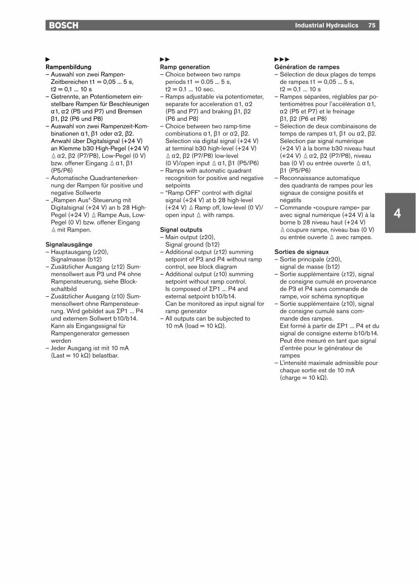
yRampenbildung– Auswahl von zwei Rampen-
Zeitbereichen t1 = 0,05 ... 5 s, t2 = 0,1 ... 10 s
– Getrennte, an Potentiometern ein-stellbare Rampen für Beschleunigenα1, α2 (P5 und P7) und Bremsenβ1, β2 (P6 und P8)
– Auswahl von zwei Rampenzeit-Kom-binationen α1, β1 oder α2, β2.Anwahl über Digitalsignal (+24 V)an Klemme b30 High-Pegel (+24 V)= α2, β2 (P7/P8), Low-Pegel (0 V)bzw. offener Eingang = α1, β1(P5/P6)
– Automatische Quadrantenerken-nung der Rampen für positive undnegative Sollwerte
– „Rampen Aus“-Steuerung mitDigitalsignal (+24 V) an b 28 High-Pegel (+24 V) = Rampe Aus, Low-Pegel (0 V) bzw. offener Eingang= mit Rampen.
Signalausgänge– Hauptausgang (z20),
Signalmasse (b12)– Zusätzlicher Ausgang (z12) Sum-
mensollwert aus P3 und P4 ohneRampensteuerung, siehe Block-schaltbild
– Zusätzlicher Ausgang (z10) Sum-mensollwert ohne Rampensteue-rung. Wird gebildet aus ΣP1 ... P4und externem Sollwert b10/b14.Kann als Eingangssignal fürRampengenerator gemessenwerden
– Jeder Ausgang ist mit 10 mA (Last = 10 kΩ) belastbar.
yyRamp generation– Choice between two ramps
periods t1 = 0.05 ... 5 s, t2 = 0.1 ... 10 sec.
– Ramps adjustable via potentiometer,separate for acceleration α1, α2 (P5 and P7) and braking β1, β2 (P6 and P8)
– Choice between two ramp-timecombinations α1, β1 or α2, β2.Selection via digital signal (+24 V)at terminal b30 high-level (+24 V)= α2, β2 (P7/P8) low-level (0 V)/open input = α1, β1 (P5/P6)
– Ramps with automatic quadrantrecognition for positive and negativesetpoints
– “Ramp OFF” control with digitalsignal (+24 V) at b 28 high-level(+24 V) = Ramp off, low-level (0 V)/open input = with ramps.
Signal outputs– Main output (z20),
Signal ground (b12)– Additional output (z12) summing
setpoint of P3 and P4 without rampcontrol, see block diagram
– Additional output (z10) summingsetpoint without ramp control.Is composed of ΣP1 ... P4 andexternal setpoint b10/b14.Can be monitored as input signal forramp generator
– All outputs can be subjected to 10 mA (load = 10 kΩ).
yyyGénération de rampes– Sélection de deux plages de temps
de rampes t1 = 0,05 ... 5 s, t2 = 0,1 ... 10 s
– Rampes séparées, réglables par po-tentiomètres pour l’accélération α1,α2 (P5 et P7) et le freinage β1, β2 (P6 et P8)
– Sélection de deux combinaisons detemps de rampes α1, β1 ou α2, β2.Sélection par signal numérique (+24 V) à la borne b30 niveau haut(+24 V) = α2, β2 (P7/P8), niveaubas (0 V) ou entrée ouverte = α1,β1 (P5/P6)
– Reconnaissance automatique des quadrants de rampes pour lessignaux de consigne positifs etnégatifs
– Commande «coupure rampe» paravec signal numérique (+24 V) à laborne b 28 niveau haut (+24 V)= coupure rampe, niveau bas (0 V)ou entrée ouverte = avec rampes.
Sorties de signaux– Sortie principale (z20),
signal de masse (b12)– Sortie supplémentaire (z12), signal
de consigne cumulé en provenancede P3 et P4 sans commande derampe, voir schéma synoptique
– Sortie supplémentaire (z10), signalde consigne cumulé sans com-mande des rampes.Est formé à partir de ΣP1 ... P4 et dusignal de consigne externe b10/b14.Peut être mesuré en tant que signald’entrée pour le générateur derampes
– L’intensité maximale admissible pourchaque sortie est de 10 mA (charge = 10 kΩ).
Industrial Hydraulics 75
4

76 Industrial Hydraulics
4
yKenngrößenFormat der Leiterkarte (100 x 160 x ca. 35) mm (B x L x H), Europaformat mit Frontplatte 7 TESteckverbindung Stecker DIN 41 612-F32Umgebungstemperatur 0 °C ... +70 °C, Lagertemperatur min. –20 °C, max. +70 °CVersorgungsspannung nominal 24 V=, Batteriespannung 21 ... 40 V UB an b16/b18 gleichgerichtete Wechselspannung Ueff = 21 ... 28 Vund b2/b4 (0 V) (einphasen, Vollweggleichrichter)Stromaufnahme max. 350 mASollwerte 2 interne Festsollwerte (+10 V/–10 V)
4 interne variable Sollwerte (+10 V ... 0 V bzw. –10 V ... 0 V)2 Eingänge für externe Sollwertvorgabe (±10 V)
Rampen 2 Rampenzeitbereiche (0,05 ... 5 s/0,1 ... 10 s)getrennter Abgleich der Beschleunigungs- und Bremsrampen„Rampe Aus“-Befehlseingang
Ausgänge Signalausgang (z20/b12)2 zusätzliche Ausgänge, ohne Rampe (z12, z10)alle Ausgänge mit 10 mA belastbar
Digitaleingänge – Signalspannung UE = +6 ... +40 V, UE nom = +24 V(Steuereingänge) – High-Signal ^ +6 V, Low-Signal % +6 V
Eingangsimpedanz Ri = 2 kΩ (Eingangsstrom ca. 10 ... 15 mA)Anzeigen/Meldungen – LED-Anzeigen für aktive Sollwerte P1 ... P4 bzw.
– Festsollwerte +10 V und –10 V– LED-Anzeige für Rampenkombination (α1, β1) oder (α2, β2)– LED-Anzeige bei „Rampe Aus“-Modus– LED-Betriebsmeldungen mit 2farbiger LED
grün: Betriebsspannung UB = Einrot: Betriebsspannung zu klein
yySpecificationsPCB Format (100 x 160 x approx. 35) mm (W x L x H), Europe format with front plate
(7 modular spacings)Plug connection Plug to DIN 41 612-F32Ambient temperature 0 °C ... +70 °C, storage temperature min. –20 °C, max. +70 °CPower supply 24 V DC nominal, battery voltage 21 ... 40 V UB to b16/b18 Rectified AC voltage Urms = 21 ... 28 Vand b2/b4 (0 V) (single-phase, full-wave rectification)Current rating Max. 350 mASetpoints 2 permanent internal setpoints (+10 V/–10 V)
4 variable internal setpoints (+10 V ... 0 V or –10 V ... 0 V)2 inputs for entry of external setpoints (±10 V)
Ramps 2 ramp periods (0.05 ... 5 s/0.1 ... 10 s)Separate adjustment of acceleration and deceleration ramps “Ramp OFF” command input
Outputs Signal output (z20/b12)2 additional outputs, without ramp (z12, z10) All outputs with load capacity of 10 mA
Digital inputs – Signal voltage UE = +6 ... +40 V, UE nom = +24 V(control inputs) – High signal ^ +6 V, low signal % +6 V
Input impedance Ri = 2 kΩ (input current approx. 10 ... 15 mA)Displays/Signals – LED display for operational setpoints P1 ... P4 and/or
– permanent +10 V and –10 V setpoints– LED for ramp combination (α1, β1) or (α2, β2)– LED for “Ramp OFF” mode– Two colour LED display for operating status
Green: Operating voltage UB = ONRed: Insufficient operating voltage
Industrial Hydraulics 77
4
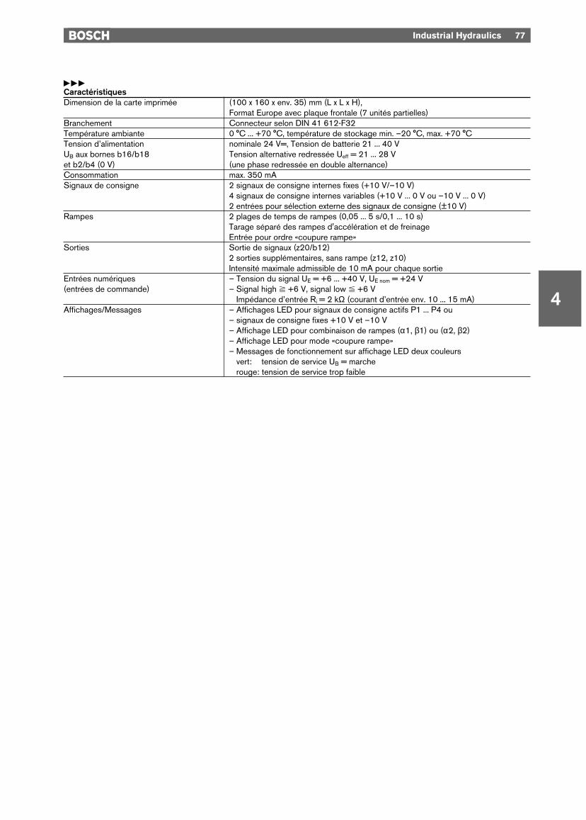
yyyCaractéristiquesDimension de la carte imprimée (100 x 160 x env. 35) mm (L x L x H),
Format Europe avec plaque frontale (7 unités partielles)Branchement Connecteur selon DIN 41 612-F32Température ambiante 0 °C ... +70 °C, température de stockage min. –20 °C, max. +70 °CTension d’alimentation nominale 24 V=, Tension de batterie 21 ... 40 V UB aux bornes b16/b18 Tension alternative redressée Ueff = 21 ... 28 Vet b2/b4 (0 V) (une phase redressée en double alternance)Consommation max. 350 mASignaux de consigne 2 signaux de consigne internes fixes (+10 V/–10 V)
4 signaux de consigne internes variables (+10 V ... 0 V ou –10 V ... 0 V)2 entrées pour sélection externe des signaux de consigne (±10 V)
Rampes 2 plages de temps de rampes (0,05 ... 5 s/0,1 ... 10 s)Tarage séparé des rampes d'accélération et de freinage Entrée pour ordre «coupure rampe»
Sorties Sortie de signaux (z20/b12)2 sorties supplémentaires, sans rampe (z12, z10) Intensité maximale admissible de 10 mA pour chaque sortie
Entrées numériques – Tension du signal UE = +6 ... +40 V, UE nom = +24 V(entrées de commande) – Signal high ^ +6 V, signal low % +6 V
Impédance d’entrée Ri = 2 kΩ (courant d’entrée env. 10 ... 15 mA)Affichages/Messages – Affichages LED pour signaux de consigne actifs P1 ... P4 ou
– signaux de consigne fixes +10 V et –10 V– Affichage LED pour combinaison de rampes (α1, β1) ou (α2, β2)– Affichage LED pour mode «coupure rampe»– Messages de fonctionnement sur affichage LED deux couleurs
vert: tension de service UB = marcherouge: tension de service trop faible

4
78 Industrial Hydraulics
Sollwert- und RampenbildnerSetpoint and ramp generatorGénérateur de consignes avecrampes
Typ VerwendungType ApplicationType Utilisation [kg] «
RAMP-LIN Abruf von Sollwerten mit spannungsgesteuerten Rampen 0,2 0 811 405 116Recall of setpoints with voltage-controlled rampsAppel de signaux de consigne avec rampes à tension commandée
FrontplatteFront platePlaque frontale

Industrial Hydraulics 79
4
Blockschaltbild mit KlemmenbelegungBlock diagram and terminal assignmentSchéma synoptique avec affectation des bornes

80 Industrial Hydraulics
4
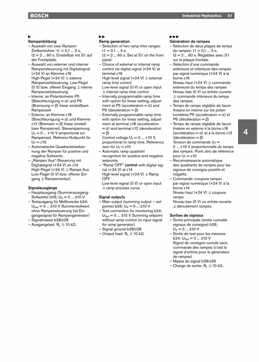
yAnwendung1. Vorbereitung und Abruf von internen
und externen Signalspannungen UE = 0 ... ±10 V.
2. Erzeugung von Signal-Spannungs-Rampen t = 0,1 ... 60 s. Rampenzeitproportional zu extern vorgegebenerSteuerspannung UT = 0 ... +10 Veinstellbar (lineare Einstellkennlinie).
Sollwertaufbereitung– 4 interne, variable Sollwerte:
Einstellbar über PotentiometerP1 ... P4 auf der Frontplatte. Versor-gung aus interner stabilisierterSpannungsquelle z32 = +10 V bzw.z30 = –10 V
– Sollwertabrufe: über Digitalsignale+24 V an den Klemmen z24, z26, z4und z2 (P1, P2, P3, P4)
– 3 Eingänge für externe Sollwert-vorgabe: (Potentialbezug auf 0 V)Eingangsspannung 0 ... ±10 V anKlemmen b10, b12 und b18 (Ein-gangsimpedanz Ri = 100 kΩ)
– 1 Eingang für externe Sollwertvor-gabe: (Ausführung als Differenzver-stärkereingang) Eingangsspannung0 ... ±10 V an den Klemmen b14(Signal) und b16 (Ref 0 V)Eingangsimpedanz Ri = 100 kΩ.
yyApplication1. Preparation and recall of internal
and external signal voltages UE = 0 ... ±10 V.
2. Generation of signal voltage rampst = 0.1 ... 60 s. Ramp time can beadjusted to be proportional to exter-nally programmed control voltageUT = 0 ... +10 V (linear adjustmentcurve).
Setpoint preparation– 4 variable internal setpoints:
Set with potentiometers P1 ... P4 on front plate. Voltage supply from internally stabilised source z32 = +10 V or z30 = –10 V.
– Setpoint access: Via digital signals+24 V at terminals z24, z26, z4 andz2 (P1, P2, P3, P4)
– 3 inputs for entry of external set-point: (0 V reference potential)Input voltage 0 ... ±10 V at terminalsb10, b12 and b18.Input impedance Ri = 100 kΩ
– 1 input for entry of external setpoint:(designed as differential amplifierinput)Input voltage 0 ... ±10 V at terminalsb14 (signal) and b16 (ref. 0 V)Input impedance Ri = 100 kΩ.
yyyApplication1. Préparation et appel de signaux de
tension internes et externes UE = 0 ... ±10 V
2. Génération de rampes de tension t = 0,1 ... 60 s. Durée de ramperéglable, proportionnelle à la ten-sion de commande présélectionnéeen externe UT = 0 ... +10 V (courbecaractéristique de réglage linéaire).
Préparation des signaux deconsigne– 4 signaux de consigne internes,
variables: réglables par le biais despotentiomètres P1 ... P4 sur la pla-que frontale. Alimentation parsource de tension interne stabilisée z32 = +10 V ou z30 = –10 V
– Appels de signaux de consigne: parl’intermédiaire de signaux numéri-ques +24 V aux bornes z24, z26, z4et z2 (P1, P2, P3, P4).
– 3 entrées pour sélection externe dessignaux de consigne (potentiel deréférence 0 V): Tension d’entrée0 ... ±10 V aux bornes b10, b12 etb18.Impédance d’entrée Ri = 100 kΩ
– 1 entrée pour sélection externe des signaux de consigne (entréeamplificateur différentiel): tensiond’entrée 0 ... ±10 V aux bornes b14 (signal) et b16 (réf. 0 V)Impédance d’entrée Ri = 100 kΩ.
Industrial Hydraulics 81
4
yRampenbildung– Auswahl von zwei Rampen-
Zeitbereichen: t1 = 0,1 ... 3 s, t2 = 2 ... 60 s. Einstellbar mit S1 aufder Frontplatte.
– Auswahl von externer und internerRampensteuerung mit Digitalsignal(+24 V) an Klemme z16High-Pegel (+24 V) = externeRampenzeitsteuerung, Low-Pegel (0 V) bzw. offener Eingang = interneRampenzeitsteuerung
– Interne, an Potentiometer P5(Beschleunigung = α) und P6(Bremsung = β) linear einstellbareRampenzeit
– Externe, an Klemme z18(Beschleunigung = α) und Klemmez12 (Bremsen = β) linear einstell-bare Rampenzeit. SteuerspannungUT = 0 ... +10 V proportional zurRampenzeit. Referenz-Nullpunkt fürUT = z10
– Automatische Quadrantenerken-nung der Rampen für positive undnegative Sollwerte.
– „Rampen Aus“-Steuerung mitDigitalsignal (+24 V) an z14 High-Pegel (+24 V) = Rampe AusLow-Pegel (0 V) bzw. offener Ein-gang = Rampenverlauf.
Signalausgänge– Hauptausgang (Summenausgang-
Sollwerte) b26; UA = 0 ... ±10 V– Testausgang für Meßzwecke b24;
UTest = 0 ... ±10 V Summensollwertohne Rampensteuerung (ist Ein-gangssignal für Rampengenerator)
– Signalmasse b28/z28– Ausgangslast: RL ^ 10 kΩ.
yyRamp generation– Selection of two ramp time ranges:
t1 = 0.1 ... 3 s. t2 = 2 ... 60 s. Set at S1 on the frontpanel.
– Choice of external or internal rampcontrol via digital signal (+24 V) atterminal z16High-level signal (+24 V) = externalramp time controlLow-level signal (0 V) or open input= internal ramp time control
– Internally programmable ramp timewith option for linear setting, adjust-ment at P5 (acceleration = α) andP6 (deceleration = β)
– Externally programmable ramp timewith option for linear setting, adjust-ment at terminal z18 (acceleration = α) and terminal z12 (deceleration= β)Control voltage UT = 0 ... +10 V,proportional to ramp time. Referencezero for UT = z10
– Automatic ramp quadrantrecognition for positive and negativesetpoints.
– “Ramp OFF” control with digital sig-nal (+24 V) at z14 High-level signal (+24 V) = RampOFFLow-level signal (0 V) or open input= ramp process curve.
Signal outputs– Main output (summing output – set-
points) b26; UA = 0 ... ±10 V– Test connection for monitoring b24;
UTest = 0 ... ±10 V Summing setpointwithout ramp control (is input signalfor ramp generator)
– Signal ground b28/z28– Output load: RL ^ 10 kΩ.
yyyGénération de rampes– Sélection de deux plages de temps
de rampes: t1 = 0,1 ... 3 s, t2 = 2 ... 60 s. Réglables avec S1sur la plaque frontale.
– Sélection d’une commandeextérieure et intérieure des rampespar signal numérique (+24 V) à laborne z16Niveau haut (+24 V) = commandeextérieure du temps des rampesNiveau bas (0 V) ou entrée ouverte= commande intérieure du tempsdes rampes
– Temps de rampe réglable de façonlinéaire en interne sur les poten-tiomètres P5 (accélération = α) etP6 (décélération = β)
– Temps de rampe réglable de façonlinéaire en externe à la borne z18(accélération = α) et à la borne z12(décélération = β)Tension de commande UT =0 ... +10 V proportionnelle du tempsdes rampes. Point zéro de référencepour UT = z10
– Reconnaissance automatique des quadrants de rampes pour lessignaux de consigne positifs etnégatifs.
– Commande «coupure rampe» par signal numérique (+24 V) à laborne z14 Niveau haut (+24 V) = coupurerampeNiveau bas (0 V) ou entrée ouverte= déroulement rampes.
Sorties de signaux– Sortie principale (sortie cumulée
signaux de consigne) b26; UA = 0 ... ±10 V
– Sortie de test pour les mesuresb24; UTest = 0 ... ±10 VSignal de consigne cumulé sanscommande des rampes (c’est lesignal d’entrée pour le générateurde rampes)
– Masse du signal b28/z28– Charge de sortie: RL ^ 10 kΩ.

82 Industrial Hydraulics
4
yKenngrößenFormat der Leiterkarte (100 x 160 x ca. 35) mm (B x L x H), Europaformat mit Frontplatte 7 TESteckverbindung Stecker DIN 41 612-F32Umgebungstemperatur 0 °C ... +70 °C, Lagertemperatur min. –20 °C, max. +70 °CVersorgungsspannung nominal 24 V=, Batteriespannung 21 ... 40 V;UB an b32 gleichgerichtete Wechselspannung Ueff = 21 ... 28 Vund 0 V an b2 (einphasen, Vollweggleichrichter)Stromaufnahme max. 350 mASollwerte 4 interne variable Sollwerte (+10 V ... 0 V bzw. –10 V ... 0 V)
3 Eingänge für externe Sollwertvorgabe (±10 V)1 Eingang für externen Sollwert (±10 V) – Differenzeingang
Rampen 2 Rampenzeitbereiche (0,1 ... 3 s/2 ... 60 s)getrennter Abgleich der Beschleunigungs- und Bremsrampen„Rampe Aus“-BefehlseingangExterne Vorgabemöglichkeit für spannungsgesteuerte Rampen
Ausgänge Signalausgang (z20/b12); ±10 V, 10 mA belastbarTestausgang (b24) ohne Rampenfunktion; 10 mA belastbar
Digitaleingänge – Signalspannung UE = +6 ... +40 V, UE nom = +24 V(Steuereingänge) – High-Signal ^ +6 V,
– Low-Signal % +6 V– Eingangsimpedanz Ri = 2 kΩ (Eingangsstrom ca. 10 ... 15 mA)
Anzeigen/Meldungen – LED-Anzeigen (gelb) für aktive Sollwerte P1 ... P4 – LED-Anzeigen (grün) für interne oder externe Rampenzeiteinstellung– Led-Anzeige (gelb) für „abgeschaltete Rampe“ ∆T = 0– 2 LED-Anzeigen (grün) für Rampenausgang– a) LED-UA = 0: LED leuchtet wenn Rampenausgang = 0– b) LED-UA = UE: LED leuchtet wenn Rampenausgang = Summe der – b) Sollwerteingänge– 2 LED-Betriebsmeldungen: LED (grün) = Betriebsspannung UB = Ein
LED (rot) = Betriebsspannung zu klein– Digitalausgang b4 = +24 V; Ausgangslast RL ^ 10 kΩ
Meldung (High-Pegel): Rampenausgangssignal hat Sollwerteingangssignalerreicht
– Digitalausgang b30 = +24 V; Ausgangslast RL ^ 10 kΩ,Meldung (High-Pegel): Rampenausgangssignal hat 0 V erreicht
Industrial Hydraulics 83
4
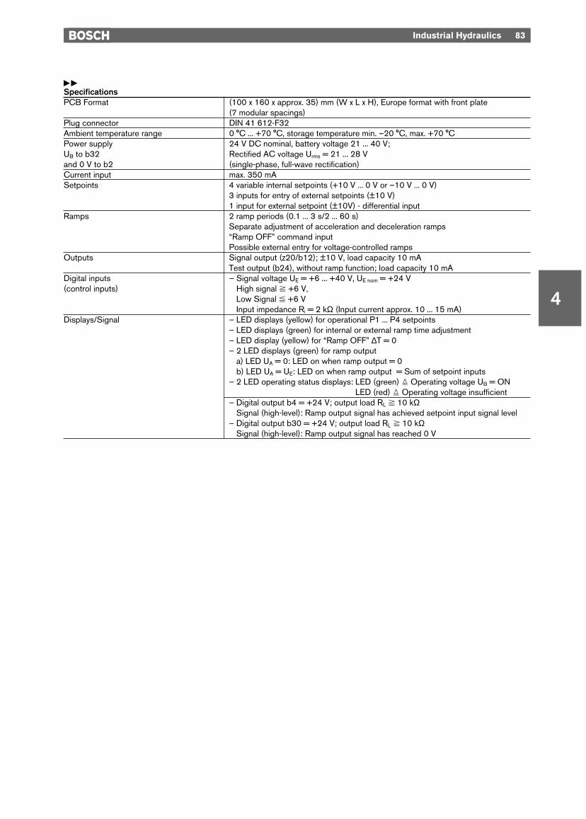
yySpecificationsPCB Format (100 x 160 x approx. 35) mm (W x L x H), Europe format with front plate
(7 modular spacings)Plug connector DIN 41 612-F32Ambient temperature range 0 °C ... +70 °C, storage temperature min. –20 °C, max. +70 °CPower supply 24 V DC nominal, battery voltage 21 ... 40 V;UB to b32 Rectified AC voltage Urms = 21 ... 28 Vand 0 V to b2 (single-phase, full-wave rectification)Current input max. 350 mASetpoints 4 variable internal setpoints (+10 V ... 0 V or –10 V ... 0 V)
3 inputs for entry of external setpoints (±10 V)1 input for external setpoint (±10V) - differential input
Ramps 2 ramp periods (0.1 ... 3 s/2 ... 60 s)Separate adjustment of acceleration and deceleration ramps“Ramp OFF” command inputPossible external entry for voltage-controlled ramps
Outputs Signal output (z20/b12); ±10 V, load capacity 10 mATest output (b24), without ramp function; load capacity 10 mA
Digital inputs – Signal voltage UE = +6 ... +40 V, UE nom = +24 V(control inputs) – High signal ^ +6 V,
– Low Signal % +6 V– Input impedance Ri = 2 kΩ (Input current approx. 10 ... 15 mA)
Displays/Signal – LED displays (yellow) for operational P1 ... P4 setpoints– LED displays (green) for internal or external ramp time adjustment– LED display (yellow) for “Ramp OFF” ∆T = 0– 2 LED displays (green) for ramp output– a) LED UA = 0: LED on when ramp output = 0– b) LED UA = UE: LED on when ramp output = Sum of setpoint inputs– 2 LED operating status displays: LED (green) = Operating voltage UB = ON
LED (red) = Operating voltage insufficient– Digital output b4 = +24 V; output load RL ^ 10 kΩ
Signal (high-level): Ramp output signal has achieved setpoint input signal level– Digital output b30 = +24 V; output load RL ^ 10 kΩ
Signal (high-level): Ramp output signal has reached 0 V
84 Industrial Hydraulics
4
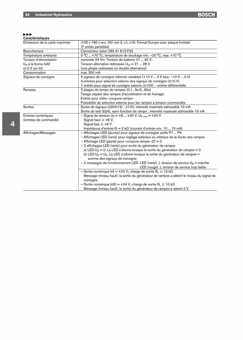
yyyCaractéristiquesDimension de la carte imprimée (100 x 160 x env. 35) mm (L x L x H), Format Europe avec plaque frontale
(7 unités partielles)Branchement Connecteur selon DIN 41 612-F32Température ambiante 0 °C ... +70 °C, température de stockage min. –20 °C, max. +70 °CTension d’alimentation nominale 24 V=, Tension de batterie 21 ... 40 V;UB à la borne b32 Tension alternative redressée Ueff = 21 ... 28 Vet 0 V sur b2 (une phase redressée en double alternance)Consommation max. 350 mASignaux de consigne 4 signaux de consigne internes variables (+10 V ... 0 V bzw. –10 V ... 0 V)
3 entrées pour sélection externe des signaux de consigne (±10 V)1 entrée pour signal de consigne externe (±10V) – entrée différentielle
Rampes 2 plages de temps de rampes (0,1...3s/2...60s)Tarage séparé des rampes d'accélération et de freinageEntrée pour ordre «coupure rampe»Possibilité de sélection externe pour les rampes à tension commandée
Sorties Sortie de signaux (z20/b12) ; ±10V, intensité maximale admissible 10 mASortie de test (b24), sans fonction de rampe ; intensité maximale admissible 10 mA
Entrées numériques – Signal de tension UE = +6 ... +40 V, UE nom = +24 V(entrées de commande) – Signal haut ^ +6 V,
– Signal bas % +6 V– Impédance d’entrée Ri = 2 kΩ (courant d’entrée env. 10 ... 15 mA)
Affichages/Messages – Affichages LED (jaunes) pour signaux de consigne actifs P1 ... P4 – Affichages LED (verts) pour réglage extérieur ou intérieur de la durée des rampes– Affichage LED (jaune) pour «coupure rampe» ∆T = 0– 2 affichages LED (verts) pour sortie du générateur de rampes– a) LED-UA = 0: La LED s’allume lorsque la sortie du générateur de rampes = 0– b) LED-UA = UE: La LED s’allume lorsque la sortie du générateur de rampes = – b) somme des signaux de consigne– 2 messages de fonctionnement LED: LED (verte) = tension de service UB = marche
LED (rouge) = tension de service trop faible– Sortie numérique b4 = +24 V; charge de sortie RL ^ 10 kΩ
Message (niveau haut): la sortie du générateur de rampes a atteint le niveau du signal deconsigne
– Sortie numérique b30 = +24 V; charge de sortie RL ^ 10 kΩMessage (niveau haut): la sortie du générateur de rampes a atteint 0 V
4
Industrial Hydraulics 85
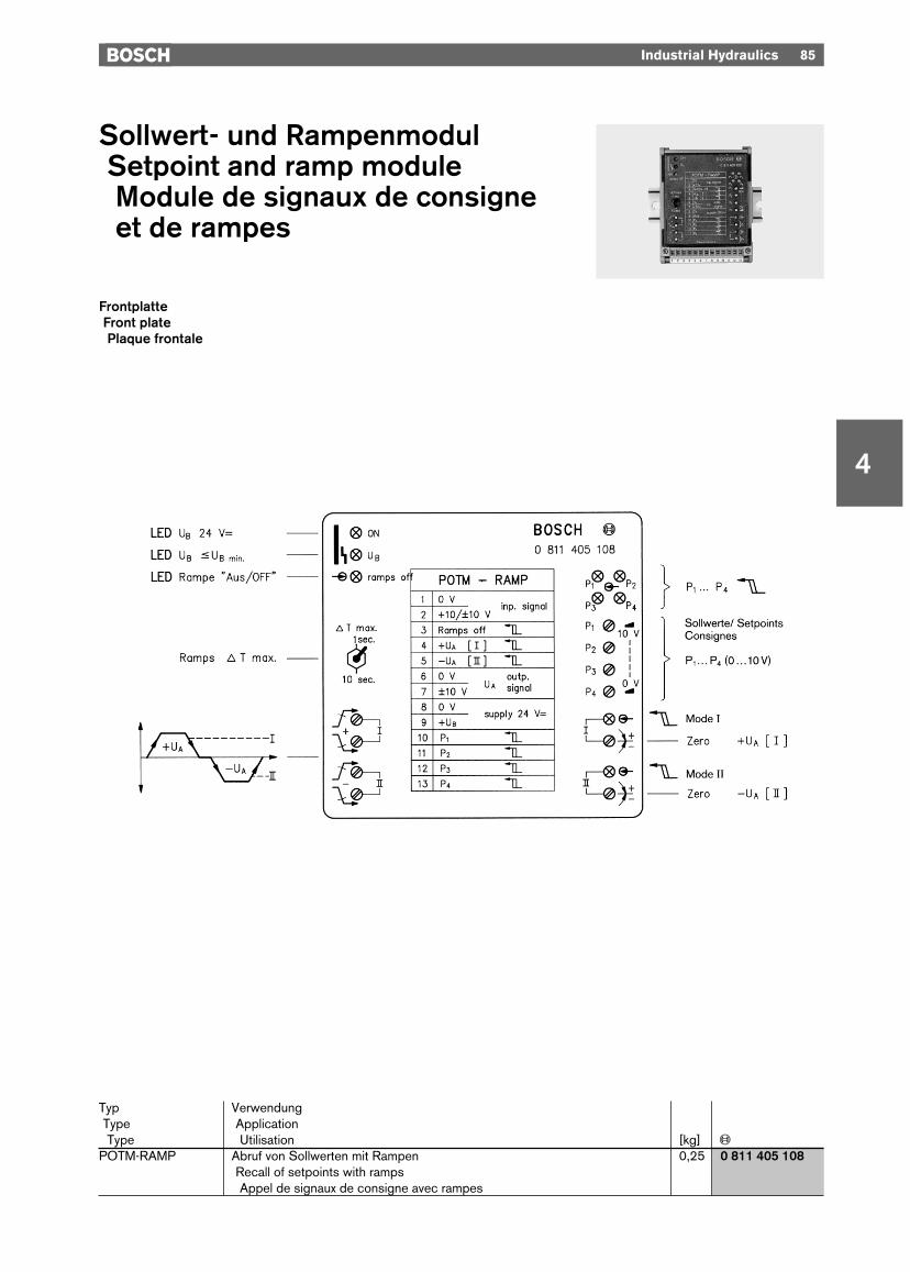
Sollwert- und RampenmodulSetpoint and ramp moduleModule de signaux de consigneet de rampes
Typ VerwendungType ApplicationType Utilisation [kg] «
POTM-RAMP Abruf von Sollwerten mit Rampen 0,25 0 811 405 108Recall of setpoints with rampsAppel de signaux de consigne avec rampes
FrontplatteFront platePlaque frontale

86 Industrial Hydraulics
4
Blockschaltbild mit KlemmenbelegungBlock diagram and terminal assignmentSchéma synoptique avec affectation des bornes
ySollwert-Rampen-Modul– Für Proportionalventile mit
eingebauter Elektronik– Sollwerte intern: P1 ... P4
– Sollwert Eingang UE
– Richtungs-Logik (±)– Einstellbare Rampen– Modesignal
I für +UA
II für –UA
I + II für ±UA
– Wahlschalter für ∆Tmax
– Eingang für „Rampen AUS“
yySetpoint ramp module– For proportional valves with
integrated amplifier– Setpoints, internal: P1 ... P4
– Setpoint input UE
– Directional logic (±)– Adjustable ramps– Mode signal
I for +UA
II for –UA
I + II for ±UA
– Selector switch for ∆Tmax
– Input for “Ramps OFF”
yyyModule de rampes et de signaux de consigne– Pour valves à effet proportionnel
avec amplificateur intégré– Signaux de consigne internes:
P1 ... P4
– Entrée de signal de consigne UE
– Logique de direction (±)– Rampes réglables– Signal de mode
I pour +UA
II pour –UA
I + II pour ±UA
– Sélecteur pour ∆Tmax
– Entrée pour «Coupure rampes»
Industrial Hydraulics 87
4
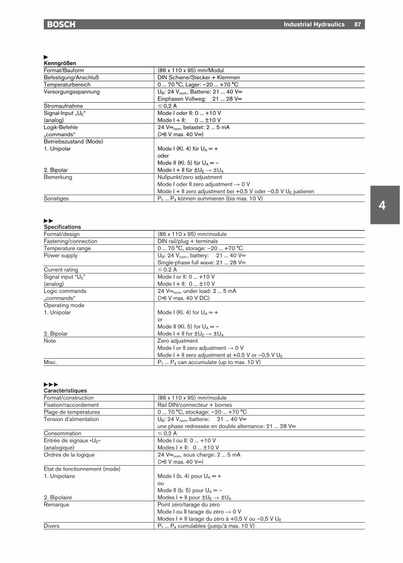
yKenngrößenFormat/Bauform (86 x 110 x 95) mm/ModulBefestigung/Anschluß DIN Schiene/Stecker + KlemmenTemperaturbereich 0 ... 70 °C, Lager: –20 ... +70 °CVersorgungsspannung UB: 24 Vnom., Batterie: 21 ... 40 V=
Einphasen Vollweg: 21 ... 28 V=Stromaufnahme # 0,2 ASignal-Input „UE“ Mode I oder II: 0 ... +10 V(analog) Mode I + II: 0 ... ±10 VLogik-Befehle 24 V=nom, belastet: 2 ... 5 mA„commands“ (>6 V max. 40 V=)Betriebszustand (Mode)1. Unipolar Mode I (Kl. 4) für UA = +
oderMode II (Kl. 5) für UA = –
2. Bipolar Mode I + II für ±UE R ±UA
Bemerkung Nullpunkt/zero adjustmentMode I oder II zero adjustment R 0 VMode I + II zero adjustment bei +0,5 V oder –0,5 V UE justieren
Sonstiges P1 ... P4 können summieren (bis max. 10 V)
yySpecificationsFormat/design (86 x 110 x 95) mm/moduleFastening/connection DIN rail/plug + terminalsTemperature range 0 ... 70 °C, storage: –20 ... +70 °CPower supply UB: 24 Vnom., battery: 21 ... 40 V=
Single-phase full wave: 21 ... 28 V=Current rating # 0.2 ASignal input “UE” Mode I or II: 0 ... +10 V(analog) Mode I + II: 0 ... ±10 VLogic commands 24 V=nom, under load: 2 ... 5 mA„commands“ (>6 V max. 40 V DC)Operating mode1. Unipolar Mode I (Kl. 4) for UA = +
orMode II (Kl. 5) for UA = –
2. Bipolar Mode I + II for ±UE R ±UA
Note Zero adjustmentMode I or II zero adjustment R 0 VMode I + II zero adjustment at +0.5 V or –0,5 V UE
Misc. P1 ... P4 can accumulate (up to max. 10 V)
yyyCaractéristiquesFormat/construction (86 x 110 x 95) mm/moduleFixation/raccordement Rail DIN/connecteur + bornesPlage de températures 0 ... 70 °C, stockage: –20 ... +70 °CTension d’alimentation UB: 24 Vnom, batterie: 21 ... 40 V=
une phase redressée en double alternance: 21 ... 28 V=Consommation # 0,2 AEntrée de signaux «UE» Mode I ou II: 0 ... +10 V(analogique) Modes I + II: 0 ... ±10 VOrdres de la logique 24 V=nom, sous charge: 2 ... 5 mA
(>6 V max. 40 V=)Etat de fonctionnement (mode)1. Unipolaire Mode I (b. 4) pour UA = +
ouMode II (b. 5) pour UA = –
2. Bipolaire Modes I + II pour ±UE R ±UA
Remarque Point zéro/tarage du zéroMode I ou II tarage du zéro R 0 VModes I + II tarage du zéro à +0,5 V ou –0,5 V UE
Divers P1 ... P4 cumulables (jusqu’à max. 10 V)

4
88 Industrial Hydraulics
Digitales RampenmodulDigital ramp moduleRampe numérique modulaire
FrontplatteFront platePlaque frontale
yMit diesen 3 Tasten erfolgendie Bewegungen zwischenund innerhalb von Menü-ebenen.
Dient dem Rücksetzen vonEingabewerten (RESET).
Mit dieser Taste werdenEingabewerte bestätigt(ENTER).
Mit diesen Tasten werden in-nerhalb eines MenübildesWerte aufwärts bzw. ab-wärts eingestellt.
yyThese 3 keys are used to performtransactions between and within themenu levels.
RESET key, used to reset inputvalues.
ENTER key, used to confirm inputvalues.
With these keys, values within a menuare selected by moving up and downthe list.
yyyCes 3 touches sont utilisées poureffectuer les mouvements entre et àl’intérieur des niveaux de menus.
Sert à remettre à zéro les valeursd’entrée (RESET).
Cette touche sert à confirmer lesvaleurs d’entrée (ENTER).
Ces touches permettent de sélec-tionner des valeurs au sein d’uneimage de menu par déplacement versle haut ou vers le bas.
Typ VerwendungType ApplicationType Utilisation [kg] «
DRM 2 Speicherung und Vorgabe von Sollwertprofilen 0,85 B 830 303 581Storage and input of setpoint profilesMémorisation et sélection des profils de signaux de consigne
F 1
F 2
F 3
R
E
q
Q

yEinführung
Das Digitale Rampenmodul DRM 2gestaltet die Schnittstelle zwischenMaschinensteuerung (SPS/CNC) undHydraulikventil.
Die wichtigsten Eigenschaften undMöglichkeiten:– 8 Sollwerte (Geschwindigkeiten)
und 4 Rampen (Beschleunigung)pro Parametersatz programmierbar
– 2 Parametersätze pro Kanal– Rampenform linear oder quadratisch– Wählbare Kompensation der Ventil-
überdeckung– Abrufbefehle in 24 V-Logik– Zusätzliche Analogeingänge für
Sollwerte und Rampen für Online-Betrieb
– Normierte Anzeige der Sollwertvor-gabe zum Ventil, sowie des Ventil-Istwertes
– Menügeführte Programmierung,Anzeige und Bedienung über zwei-zeiliges Display à 20 Zeichen, Klar-text, Softkeys
– Betriebsarten:Automatik, Programmierung, Hand-betrieb und Diagnose
– Ansteuerung von 2 Proportional-ventilen gleichzeitig
– Vorzugsweise werden Ventile miteingebauter Elektronik eingesetzt.
Argumente für den Einsatz des DRM 2
– Einfache, kostengünstigeMaschinensteuerung
Modul kann in eine gängige, kosten-günstige SPS-Steuerung in Verbin-dung mit Endschaltern bzw. Wegauf-nehmern eingebunden werden.Geschwindigkeitssollwerte und Be-schleunigungssollwerte für dieAntriebe können hochgenau und vorallem reproduzierbar programmiertwerden.
– Hohe FlexibilitätVon einem DRM 2-Modul können zweiAchsen unabhängig bedient werden.Durch einfache Abrufbefehle könnenje Achse zwei vorprogrammierte Para-metersätze ausgewählt werden. Somitkönnen unterschiedlichen Betriebszu-ständen (z. B. Bewegung mit oderohne Last) verschiedene Beschleuni-gungen und Geschwindigkeiten zuge-ordnet werden. Erhöhte Flexibilitätbeim Bewegungsablauf der Achsendurch zusätzliche Analogeingänge fürGeschwindigkeit und Beschleunigung(Online-Modul).
yyIntroduction
The Digital Ramp Module DRM 2forms the interface between themachine control (PLC/CNC) and thehydraulic valve.
The most important properties andpossible functions:– 8 setpoints (speeds) and 4 ramps
(acceleration) programmable perparameter block
– 2 parameter blocks per channel– Linear or quadratic ramp form– User-defined valve-overlap compen-
sation– 24 V-logic polling commands– Additional analog inputs for set-
points and ramps for online opera-tion
– Standardized display of setpointsignal to valve and of valve feedbacksignal
– Menu-guided programming, displayand operation via two-line 20-cha-racter display, clear text, softkeys
– Modes:Automatic, Programming, Manualand Diagnosis
– Actuation of 2 proportional valvessimultaneously
– Valves with on-board electronics areprimarily employed.
Reasons for using the DRM 2
– Simple, low-cost machine controlModule can be linked into a commonlyavailable, low cost PLC control unit, incombination with limit switches or po-sition transducers. Speed and accele-ration setpoints for the drives can beprogrammed very accurately and,above all, repeatedly.
– High flexibilityTwo axes can be operated indepen-dently by one DRM 2 module. As aresult of simple polling commands,two pre-programmed parameterblocks per axis can be selected. Thismeans that different accelerations andspeeds can be assigned to differentoperating states (e.g. movement withor without load). Increased flexibility in the axis movement as a result ofadditional analog inputs for speed andacceleration (online mode).
yyyIntroduction
La rampe numérique modulaireDRM 2 forme l’interface entre la com-mande de machine (API/CN) et lavalve hydraulique.
Principales caractéristiques etfonctions possibles:– 8 valeurs de consigne (vitesses)
et 4 rampes (accélération) pro-grammables par lot de paramètres
– 2 lots de paramètres par canal– Forme de rampe linéaire ou quadra-
tique– Sélection possible de la compensa-
tion du recouvrement de la valve – Ordres d’appel en logique 24 V– Entrées analogiques supplémen-
taires pour valeurs de consigne etrampes pour fonctionnement online
– Affichage normalisé de l’entrée desvaleurs de consigne vers la valve ainsique de la valeur réelle de la valve
– Programmation commandée parmenu, affichage et commande viaaffichage à deux lignes à 20 carac-tères, en clair, touches programma-bles par l’utilisateur
– Modes de fonctionnement:automatique, programmation,manuel et diagnostic
– Pilotage simultané de 2 valves pro-portionnelles
– Utiliser de préférence des valvesavec amplificateur intégré.
Avantages offerts par l’utilisation duDRM 2
– Commande de machine simple etde coût avantageux
Le module peut être intégré dans unautomate programmable industrielcourant de prix avantageux en asso-ciation avec des capteurs de fin decourse ou des capteurs de position.Les valeurs de consigne de vitesse etd’accélération pour les commandespeuvent être programmées avec unegrande précision et surtout une bonnereproductibilité.
– Grande flexibilitéLe module DRM 2 permet de com-mander deux axes individuellement.Grâce à des ordres d’appel simples,deux lots de paramètres programmésà l’avance peuvent être sélectionnéspar axe. Il est ainsi possible d’affecterdifférentes accélérations et vitesses àdivers états de service (par ex. dépla-cement avec ou sans charge). Grandeflexibilité lors du cycle de déplacementdes axes par entrées analogiquessupplémentaires pour la vitesse etl’accélération (mode on-line).
Industrial Hydraulics 89
4
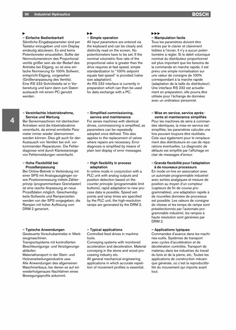
y– Einfache BedienbarkeitSämtliche Eingabeparameter sind perTastatur einzugeben und vom Displayeindeutig abzulesen. Es sind keinePotentiometer einzustellen. Sollte derNennvolumenstrom des Proportional-ventils größer sein als der Bedarf desAntriebs bei Eilgang, so ist eine ein-fache Normierung für 100% Sollwert,entspricht Eilgang, vorgesehen(Größenanpassung des Ventils). Eine RS 232-Schnittstelle ist in Vor-bereitung und kann dann zum Daten-austausch mit einem PC genutztwerden.
– Vereinfachte Inbetriebnahme,Service und Wartung
Bei Serienmaschinen mit identischenAntrieben wird die Inbetriebnahmevereinfacht, da einmal ermittelte Para-meter immer wieder übernommenwerden können. Dies gilt auch für denAustausch von Ventilen bei evtl. vor-kommenden Reparaturen. Die Fehler-diagnose wird durch Klartextanzeigevon Fehlermeldungen vereinfacht.
– Hohe Flexibilität beiProzeßanpassung
Bei Online-Betrieb in Verbindung miteiner SPS mit Analogausgängen so-wie Positionsmessung mittels Zähler-prinzip (programmierbare Grenztaster)ist eine rasche Anpassung an neueProzeßdaten möglich. Geschwindig-keits-Sollwerte und Rampenzeitenwerden von der SPS vorgegeben, dieRampen mit hoher Auflösung vomDRM 2 generiert.
– Typische AnwendungenGesteuerte Vorschubantriebe in Werk-zeugmaschinen.Transportsysteme mit kontrolliertenBeschleunigungs- und Verzögerungs-abläufen.Materialtransport in der Stein- undHolzverarbeitungsindustrie usw.Alle Anwendungen des allgemeinenMaschinenbaus, bei denen es auf einwiederholgenaues Nachfahren einesBewegungsprofils ankommt.
yy– Simple operationAll input parameters are entered viathe keyboard and can be clearly anddistinctly read on the screen. Nopotentiometers have to be set. If thenominal volumetric flow rate of theproportional valve is greater than thedrive requires at fast speed, simplestandardization to “100% setpointequals fast speed” is provided (valvesize adaptation). An RS 232 interface is currently inpreparation which can then be usedfor data exchange with a PC.
– Simplified commissioning,service and maintenance
For series machines with identicaldrives, commissioning is simplified, asparameters can be repeatedlyadopted once defined. This alsoapplies to the replacement of valveswhere repairs are necessary. Errordiagnosis is simplified by means ofplain text display of error messages.
– High flexibility in processadaptation
In online mode in conjunction with aPLC unit with analog outputs andposition detection based on thecounter principle (programmable limitbuttons), rapid adaptation to new pro-cess data is possible. Speed set-points and ramp times are specifiedby the PLC unit; the high-resolutionramps are generated by the DRM 2.
– Typical applicationsControlled feed drives in machinetools.Conveying systems with monitoredacceleration and deceleration. Materialconveying in the stone and wood pro-cessing industry etc.All general mechanical engineeringapplications in which accurate repeti-tion of movement profiles is essential.
yyy– Manipulation facileTous les paramètres doivent êtreentrés par le clavier et clairementlisibles à l’écran. Il n’y a aucun poten-tiomètre à régler. Si le débit volumiquenominal du distributeur proportionnelest plus important que les besoins dela commande en marche rapide, il estprévu une simple normalisation surune valeur de consigne de 100%correspondant à la marche rapide(adaptation de la taille du distributeur). Une interface RS 232 est actuelle-ment en préparation; elle pourra êtreutilisée pour l’échange de donnéesavec un ordinateur personnel.
– Mise en service, service après-vente et maintenance simplifiés
Pour les machines de série à comman-des identiques, la mise en service estsimplifiée, les paramètres calculés unefois pouvant toujours être réutilisés.Cela vaut également pour le remplace-ment des distributeurs en cas de répa-rations éventuelles. Le diagnostic dedéfauts est simplifié par l’affichage enclair de messages d’erreur.
– Grande flexibilité pour l’adaptationà de nouveaux processurs
En mode on-line en association avecun automate programmable industrielavec sorties analgiques et mesure deposition au moyen d’un compteur(capteurs de fin de course pro-grammables), une adaptation rapide àde nouvelles données de processusest possible. Les valeurs de consignede vitesse et les temps de rampe sontprésélectionnés par l’automate pro-grammable industriel, les rampes àhaute résolution sont générées parDRM 2.
– Applications typiquesCommandes d’avance dans les machi-nes-outils. Systèmes de transportavec cycles d’accélération et dedécélération contrôlés. Transport dematériau dans les industries du travaildu bois et de la pierre, etc. Toutes lesapplications de construction mécani-que générale, où c’est la reproductibi-lité du mouvement qui importe avanttout.
90 Industrial Hydraulics
4
Industrial Hydraulics 91
4
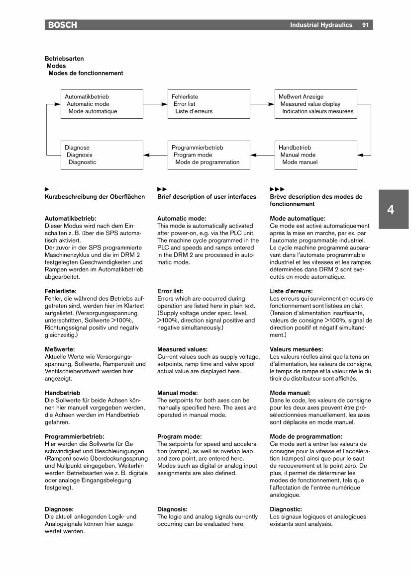
BetriebsartenModesModes de fonctionnement
yKurzbeschreibung der Oberflächen
Automatikbetrieb:Dieser Modus wird nach dem Ein-schalten z. B. über die SPS automa-tisch aktiviert.Der zuvor in der SPS programmierteMaschinenzyklus und die im DRM 2festgelegten Geschwindigkeiten undRampen werden im Automatikbetriebabgearbeitet.
Fehlerliste:Fehler, die während des Betriebs auf-getreten sind, werden hier im Klartextaufgelistet. (Versorgungsspannungunterschritten, Sollwerte >100%,Richtungssignal positiv und negativgleichzeitig.)
Meßwerte:Aktuelle Werte wie Versorgungs-spannung, Sollwerte, Rampenzeit undVentilschieberistwert werden hierangezeigt.
HandbetriebDie Sollwerte für beide Achsen kön-nen hier manuell vorgegeben werden,die Achsen werden im Handbetriebgefahren.
Programmierbetrieb:Hier werden die Sollwerte für Ge-schwindigkeit und Beschleunigungen(Rampen) sowie Überdeckungssprungund Nullpunkt eingegeben. Weiterhinwerden Betriebsarten wie z. B. digitaleoder analoge Eingangsbelegungfestgelegt.
Diagnose:Die aktuell anliegenden Logik- undAnalogsignale können hier ausge-wertet werden.
yyBrief description of user interfaces
Automatic mode:This mode is automatically activatedafter power-on, e.g. via the PLC unit.The machine cycle programmed in thePLC and speeds and ramps entered in the DRM 2 are processed in auto-matic mode.
Error list:Errors which are occurred duringoperation are listed here in plain text.(Supply voltage under spec. level,>100%, direction signal positive andnegative simultaneously.)
Measured values:Current values such as supply voltage,setpoints, ramp time and valve spoolactual value are displayed here.
Manual mode:The setpoints for both axes can bemanually specified here. The axes areoperated in manual mode.
Program mode:The setpoints for speed and accelera-tion (ramps), as well as overlap leapand zero point, are entered here.Modes such as digital or analog inputassignments are also defined.
Diagnosis:The logic and analog signals currentlyoccurring can be evaluated here.
yyyBrève description des modes defonctionnement
Mode automatique:Ce mode est activé automatiquementaprès la mise en marche, par ex. parl’automate programmable industriel.Le cycle machine programmé aupara-vant dans l’automate programmableindustriel et les vitesses et les rampesdéterminées dans DRM 2 sont exé-cutés en mode automatique.
Liste d’erreurs:Les erreurs qui surviennent en cours defonctionnement sont listées en clair.(Tension d’alimentation insuffisante,valeurs de consigne >100%, signal dedirection positif et négatif simultané-ment.)
Valeurs mesurées:Les valeurs réelles ainsi que la tensiond’alimentation, les valeurs de consigne,le temps de rampe et la valeur réelle dutiroir du distributeur sont affichés.
Mode manuel:Dans le code, les valeurs de consignepour les deux axes peuvent être pré-sélectionnées manuellement, les axessont déplacés en mode manuel.
Mode de programmation:Ce mode sert à entrer les valeurs deconsigne pour la vitesse et l’accéléra-tion (rampes) ainsi que pour le saut de recouvrement et le point zéro. Deplus, il permet de déterminer lesmodes de fonctionnement, tels quel’affectation de l’entrée numériqueanalogique.
Diagnostic:Les signaux logiques et analogiquesexistants sont analysés.
AutomatikbetriebAutomatic modeMode automatique
FehlerlisteError listListe d’erreurs
Meßwert AnzeigeMeasured value displayIndication valeurs mesurées
DiagnoseDiagnosisDiagnostic
ProgrammierbetriebProgram modeMode de programmation
HandbetriebManual modeMode manuel

92 Industrial Hydraulics
4
Anschlußplan, 7polige VentileTerminal diagram, valves with 7-pin plugSchéma des connections, valves à 7 pôles
Industrial Hydraulics 93
4
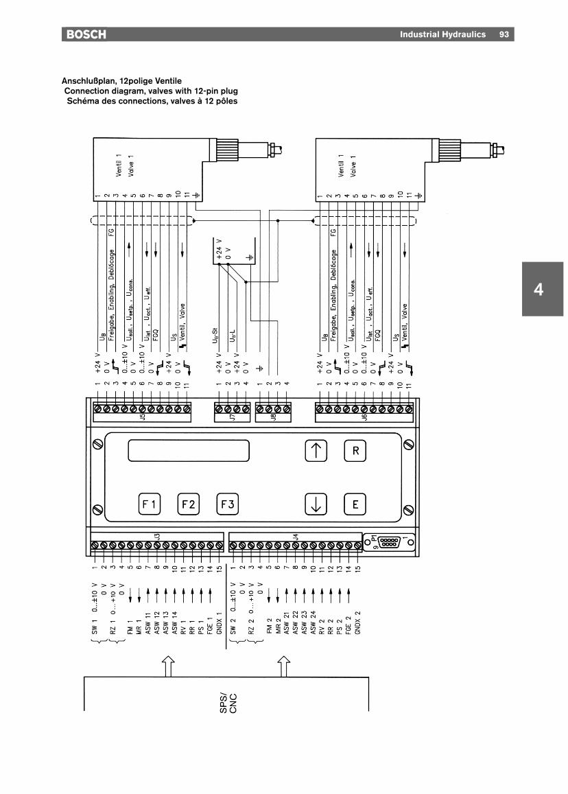
Anschlußplan, 12polige VentileConnection diagram, valves with 12-pin plugSchéma des connections, valves à 12 pôles

94 Industrial Hydraulics
4
yTechnische Daten
Versorgungs- und UmgebungsbedingungenBetriebstemperatur 0 ... +50 °CLagertemperatur –20 ... +50 °CVersorgungsspannung 24 V= nominal, min. 21 V, max. 36 V bei Welligkeit <10% UB
Stromaufnahme max. 4,4 A (2 x NG 10-Ventile)min. 3 A (2 x NG 6-Ventile)
EingängeAnaloge Sollwerte 0 ... ±10 V; Ri = 100 kΩ, Differenzeingang(J 3: 1/2 und J 4: 1/2)Analoge Rampenzeit 0 ... +10 V; Ri = 220 kΩ, Differenzeingang(J 3: 3/4 und J 4: 3/4)Steuereingänge ASW, 24 V nom., ca. 5 mA, Optokopplereingänge, min. 10 V, max. 40 VRV, RR, PS, FGEIIstwerteingang 0 ... ±10 V, Differenzeingang(J 5: 6/7 und J 6: 6/7)Meldeeingänge FS 24 V nom., ≤ 5 mA, Optokopplereingänge, max. 40 V=, H min. +10 V, L max. +2,5 VSystemschnittstelle RS 232 (in Vorbereitung)AusgängeSollwertausgänge 0 ... ±10 V; RL ≥ 10 kΩ, kurzschlußfest gegen MasseSteuerausgänge 24 V nom., max. 10 mA belastbar, kurzschlußfest gegen MasseFM, MR, FGRampenZeiten 10 ms ... 1 s; 1 s ... 10 s; 10 s ... 100sRampenform linear oder quadratischNotrampe 0 ... 200 ms (in 10-ms-Schritten programmierbar)
yyTechnical data
Power-supply and environmental conditionsOperating temperature 0 ... +50 °CStorage temperature –20 ... +50 °CSupply voltage 24 V DC nominal, min. 21 V, max. 36 V with ripple <10% UB
Current rating Max. 4.4 A (2 x NG 10 valves)Min. 3 A (2 x NG 6 valves)
InputsAnalog setpoints 0 ... ±10 V; Ri = 100 kΩ, difference input(J 3: 1/2 and J 4: 1/2)Analog ramp time 0 ... +10 V; Ri = 220 kΩ, difference input(J 3: 3/4 and J 4: 3/4)Control inputs ASW, 24 V nom., approx. 5 mA, optocoupler inputs min. 10 V, max. 40 VRV, RR, PS, FGEIFeedback signal input 0 ... ±10 V, difference input(J 5: 6/7 and J 6: 6/7)Message inputs FS 24 V nom., ≤ 5 mA, optocoupler inputs max. 40 V DC, H min. +10 V, L max. +2.5 VSystem interface RS 232 (in preparation)OutputsSetpoint outputs 0 ... ±10 V; RL ≥ 10 kΩ, short-circuit-proof to groundControl outputs 24 V nom., max. load carrying capacity 10 mA, short-circuit-proof to groundFM, MR, FGRampsTimes 10 ms ... 1 s; 1 s ... 10 s; 10 s ... 100sRamp form Linear or quadraticEmergency ramp 0 ... 200 ms (programmable in increments of 10 ms)
Industrial Hydraulics 95
4
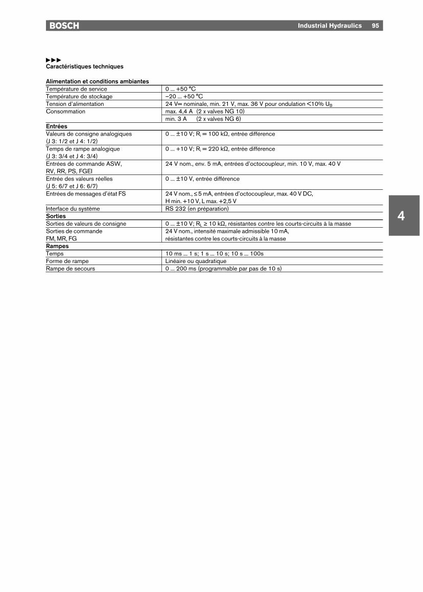
yyyCaractéristiques techniques
Alimentation et conditions ambiantesTempérature de service 0 ... +50 °CTempérature de stockage –20 ... +50 °CTension d’alimentation 24 V= nominale, min. 21 V, max. 36 V pour ondulation <10% UB
Consommation max. 4,4 A (2 x valves NG 10)min. 3 A (2 x valves NG 6)
EntréesValeurs de consigne analogiques 0 ... ±10 V; Ri = 100 kΩ, entrée différence(J 3: 1/2 et J 4: 1/2)Temps de rampe analogique 0 ... +10 V; Ri = 220 kΩ, entrée différence(J 3: 3/4 et J 4: 3/4)Entrées de commande ASW, 24 V nom., env. 5 mA, entrées d’octocoupleur, min. 10 V, max. 40 VRV, RR, PS, FGEIEntrée des valeurs réelles 0 ... ±10 V, entrée différence(J 5: 6/7 et J 6: 6/7)Entrées de messages d’état FS 24 V nom., ≤ 5 mA, entrées d’octocoupleur, max. 40 V DC,
H min. +10 V, L max. +2,5 VInterface du système RS 232 (en préparation)SortiesSorties de valeurs de consigne 0 ... ±10 V; RL ≥ 10 kΩ, résistantes contre les courts-circuits à la masseSorties de commande 24 V nom., intensité maximale admissible 10 mA, FM, MR, FG résistantes contre les courts-circuits à la masseRampesTemps 10 ms ... 1 s; 1 s ... 10 s; 10 s ... 100sForme de rampe Linéaire ou quadratiqueRampe de secours 0 ... 200 ms (programmable par pas de 10 s)
4
96 Industrial Hydraulics
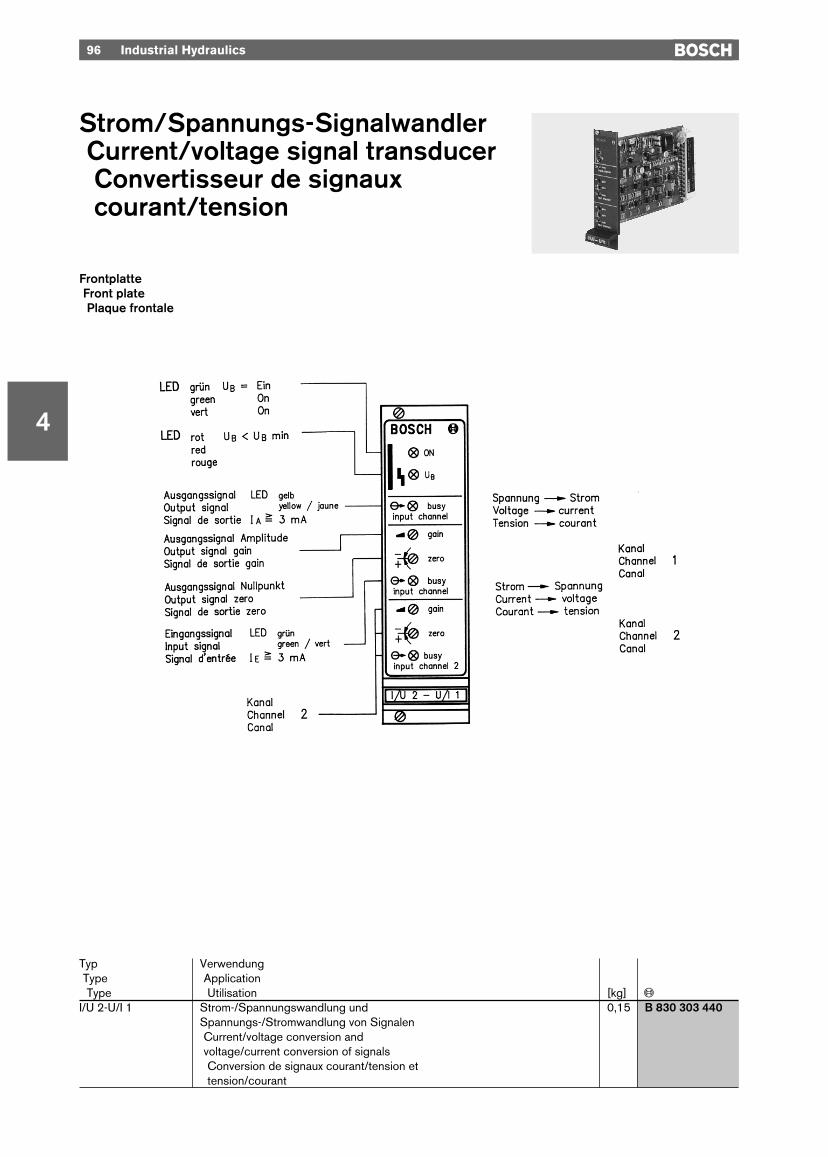
Strom/Spannungs-SignalwandlerCurrent/voltage signal transducerConvertisseur de signauxcourant/tension
FrontplatteFront platePlaque frontale
Typ VerwendungType ApplicationType Utilisation [kg] «
I/U 2-U/I 1 Strom-/Spannungswandlung und 0,15 B 830 303 440Spannungs-/Stromwandlung von SignalenCurrent/voltage conversion and voltage/current conversion of signalsConversion de signaux courant/tension ettension/courant
Industrial Hydraulics 97
4
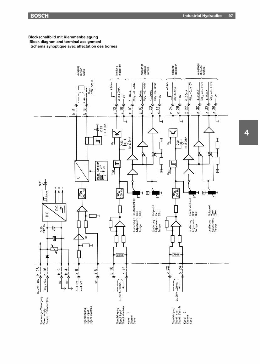
Blockschaltbild mit KlemmenbelegungBlock diagram and terminal assignmentSchéma synoptique avec affectation des bornes
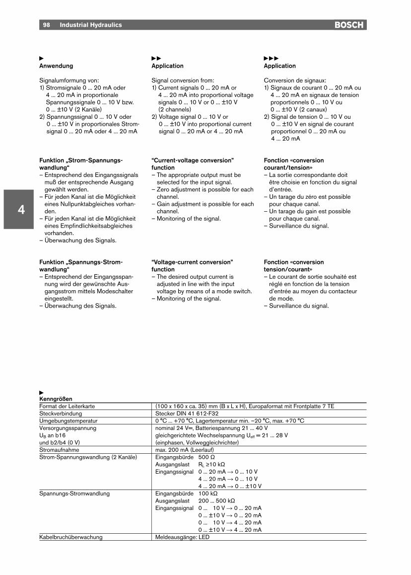
yAnwendung
Signalumformung von:1) Stromsignale 0 ... 20 mA oder
4 ... 20 mA in proportionaleSpannungssignale 0 ... 10 V bzw.0 ... ±10 V (2 Kanäle)
2) Spannungssignal 0 ... 10 V oder 0 ... ±10 V in proportionales Strom-signal 0 ... 20 mA oder 4 ... 20 mA
Funktion „Strom-Spannungs-wandlung“– Entsprechend des Eingangssignals
muß der entsprechende Ausganggewählt werden.
– Für jeden Kanal ist die Möglichkeiteines Nullpunktabgleiches vorhan-den.
– Für jeden Kanal ist die Möglichkeiteines Empfindlichkeitsabgleichesvorhanden.
– Überwachung des Signals.
Funktion „Spannungs-Strom-wandlung“– Entsprechend der Eingangsspan-
nung wird der gewünschte Aus-gangsstrom mittels Modeschaltereingestellt.
– Überwachung des Signals.
yyApplication
Signal conversion from:1) Current signals 0 ... 20 mA or
4 ... 20 mA into proportional voltagesignals 0 ... 10 V or 0 ... ±10 V (2 channels)
2) Voltage signal 0 ... 10 V or 0 ... ±10 V into proportional currentsignal 0 ... 20 mA or 4 ... 20 mA
“Current-voltage conversion”function– The appropriate output must be
selected for the input signal.– Zero adjustment is possible for each
channel.– Gain adjustment is possible for each
channel.– Monitoring of the signal.
“Voltage-current conversion”function– The desired output current is
adjusted in line with the inputvoltage by means of a mode switch.
– Monitoring of the signal.
yyyApplication
Conversion de signaux:1) Signaux de courant 0 ... 20 mA ou
4 ... 20 mA en signaux de tensionproportionnels 0 ... 10 V ou 0 ... ±10 V (2 canaux)
2) Signal de tension 0 ... 10 V ou0 ... ±10 V en signal de courantproportionnel 0 ... 20 mA ou 4 ... 20 mA
Fonction «conversion courant/tension»– La sortie correspondante doit
être choisie en fonction du signald’entrée.
– Un tarage du zéro est possible pour chaque canal.
– Un tarage du gain est possible pour chaque canal.
– Surveillance du signal.
Fonction «conversion tension/courant»– Le courant de sortie souhaité est
réglé en fonction de la tensiond’entrée au moyen du contacteur de mode.
– Surveillance du signal.
98 Industrial Hydraulics
4
yKenngrößenFormat der Leiterkarte (100 x 160 x ca. 35) mm (B x L x H), Europaformat mit Frontplatte 7 TESteckverbindung Stecker DIN 41 612-F32Umgebungstemperatur 0 °C ... +70 °C, Lagertemperatur min. –20 °C, max. +70 °CVersorgungsspannung nominal 24 V=, Batteriespannung 21 ... 40 V UB an b16 gleichgerichtete Wechselspannung Ueff = 21 ... 28 Vund b2/b4 (0 V) (einphasen, Vollweggleichrichter)Stromaufnahme max. 200 mA (Leerlauf)Strom-Spannungswandlung (2 Kanäle) Eingangsbürde 500 Ω
Ausgangslast RL ≥10 kΩEingangssignal 0 ... 20 mA R 0 ... 10 V
4 ... 20 mA R 0 ... 10 V4 ... 20 mA R 0 ... ±10 V
Spannungs-Stromwandlung Eingangsbürde 100 kΩAusgangslast 200 ... 500 kΩEingangssignal 0 ... ±10 V R 0 ... 20 mA
0 ... ±10 V R 0 ... 20 mA0 ... ±10 V R 4 ... 20 mA0 ... ±10 V R 4 ... 20 mA
Kabelbruchüberwachung Meldeausgänge: LED

Industrial Hydraulics 99
4
yyyCaractéristiquesDimension de la carte imprimée (100 x 160 x env. 35) mm (L x L x H),
Format Europe avec plaque frontale (7 unités partielles)Branchement Connecteur selon DIN 41 612-F32Température ambiante 0 °C ... +70 °C, température de stockage min. –20 °C, max. +70 °CTension d’alimentation nominale 24 V=, Tension de batterie 21 ... 40 V UB aux bornes b16 Tension alternative redressée Ueff = 21 ... 28 Vet b2/b4 (0 V) (une phase redressée en double alternance)Consommation max. 200 mA (en circuit ouvert)Conversion courant/tension (2 canaux) Charge d’entrée 500 Ω
Charge de sortie RL ≥10 kΩSignal d’entrée 0 ... 20 mA R 0 ... 10 V
4 ... 20 mA R 0 ... 10 V4 ... 20 mA R 0 ... ±10 V
Conversion tension-courant Charge d’entrée 100 kΩCharge de sortie 200 ... 500 kΩSignal d’entrée 0 ... >10 V R 0 ... 20 mA
0 ... ±10 V R 0 ... 20 mA0 ... >10 V R 4 ... 20 mA0 ... ±10 V R 4 ... 20 mA
Surveillance rupture de câble Sorties d’indication: LED
yySpecificationsPCB Format (100 x 160 x approx. 35) mm (W x L x H), Europe format with front plate
(7 modular spacings)Plug connection Plug to DIN 41 612-F32Ambient temperature range 0 °C ... +70 °C, storage temperature min. –20 °C, max. +70 °CPower supply 24 V DC nominal, battery voltage 21 ... 40 V UB to b16 Rectified AC voltage Urms = 21 ... 28 Vand b2/b4 (0 V) (single-phase, full-wave rectification)Current rating max. 200 mA (open circuit)Current-voltage conversion (2 channels) Input burden 500 Ω
Output load RL ≥10 kΩInput signal 0 ... 20 mA R 0 ... 10 V
4 ... 20 mA R 0 ... 10 V4 ... 20 mA R 0 ... ±10 V
Voltage-current conversion Input burden 100 kΩOutput load 200 ... 500 kΩInput signal 0 ... >10 V R 0 ... 20 mA
0 ... ±10 V R 0 ... 20 mA0 ... >10 V R 4 ... 20 mA0 ... ±10 V R 4 ... 20 mA
Cable break monitoring Signal outputs; LED
4
100 Industrial Hydraulics
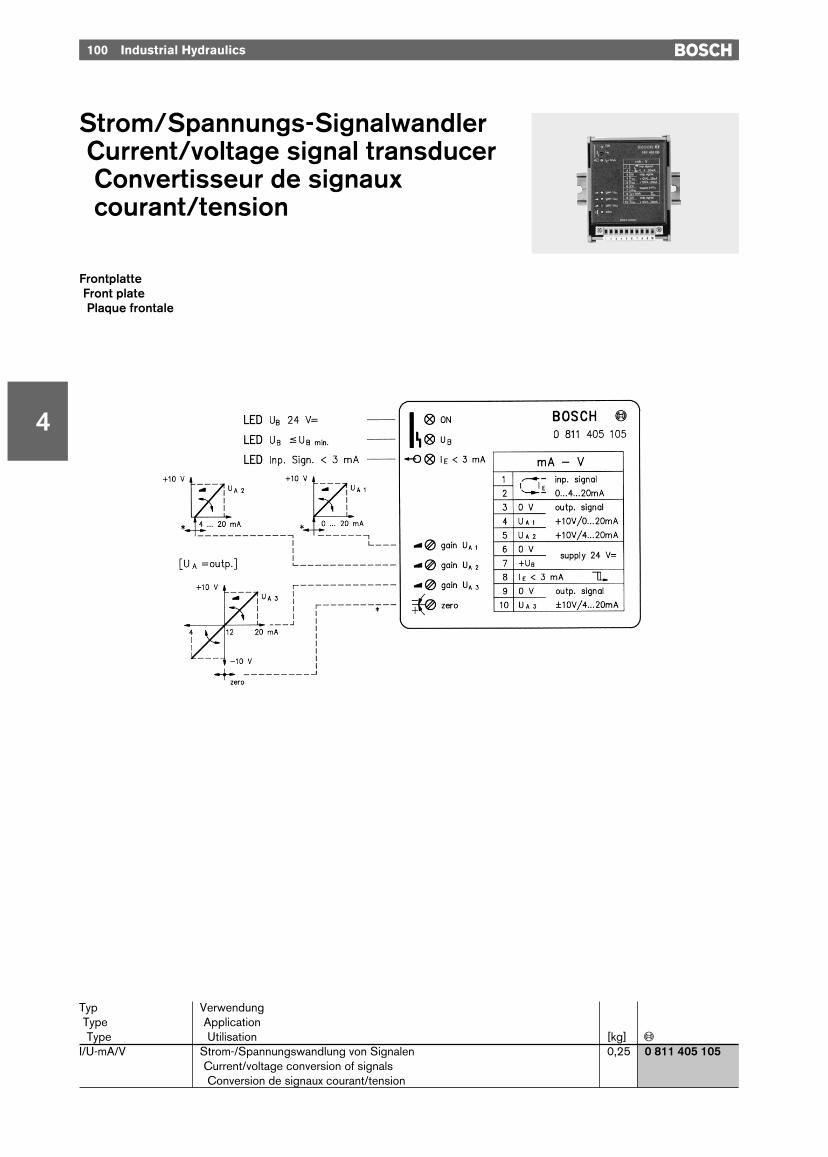
Strom/Spannungs-SignalwandlerCurrent/voltage signal transducerConvertisseur de signauxcourant/tension
Typ VerwendungType ApplicationType Utilisation [kg] «
I/U-mA/V Strom-/Spannungswandlung von Signalen 0,25 0 811 405 105Current/voltage conversion of signalsConversion de signaux courant/tension
FrontplatteFront platePlaque frontale
Industrial Hydraulics 101
4
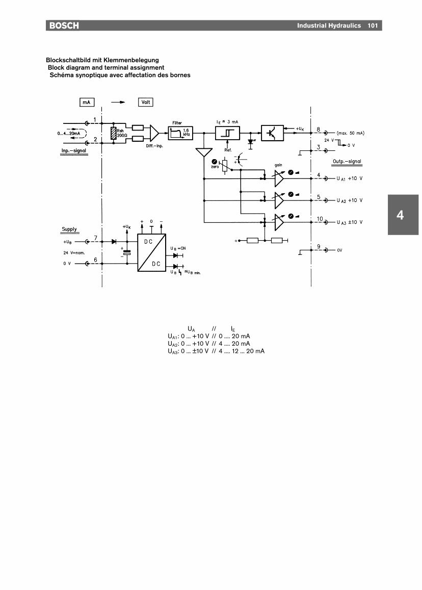
Blockschaltbild mit KlemmenbelegungBlock diagram and terminal assignmentSchéma synoptique avec affectation des bornes
UAUAUA // IEIEIEIEUA1: 0 ... +10 V // 0 .... 20 mAUA2: 0 ... +10 V // 4 .... 20 mAUA3: 0 ... ±10 V // 4 .... 12 ... 20 mA

102 Industrial Hydraulics
4
yKenngrößenFormat/Bauform (86 x 110 x 95) mm/ModulBefestigung/Anschluß DIN-Schiene/Stecker mit SchraubklemmenUmgebungstemperatur 0 ... 70 °C, Lager –20 ... +70 °CVersorgungsspannung UB: 24 Vnom, Batt.: 21 ... 40 V=
Einphasen Vollweg: 21 ... 28 V=eff
Stromaufnahme ca. 0,1 ASignaleingang 0 ... 20 mA Differenzverstärker mit Shunt 200 ΩSignalausgänge: (max. 10 kΩ Last) UA1: 0 ... +10 V (0 ... 20 mA)
UA2: 0 ... +10 V (4 ... 20 mA)UA3: 0 ... ±10 V (4 ... 12 ... 20 mA)
Logikausgang „Kl. 8“ 24 V=nom R 0 V, 24 V 0 V,IE ≤3 mA mit max. 50 mA belastbar
yySpecifiactionsFormat/design (86 x 110 x 95) mm/moduleFastening/connection DIN rail/plug with screw terms.Ambient temperature 0 ... 70 °C, Storage –20 ... +70 °CPower supply UB: 24 Vnom, batt.: 21 ... 40 V DC
Single-phase full wave: 21 ... 28 V DCeff
Current rating Approx. 0.1 ASignal input 0 ... 20 mA Difference amplifier with shunt 200 ΩSignal outputs: (max. 10 kΩ load) UA1: 0 ... +10 V (0 ... 20 mA)
UA2: 0 ... +10 V (4 ... 20 mA)UA3: 0 ... ±10 V (4 ... 12 ... 20 mA)
Logic output “Term. 8” 24 V DCnom R 0 V, 24 V 0 V,IE ≤3 mA max. load capacity 50 mA
yyyCaractéristiquesFormat/construction (86 x 110 x 95) mm/moduleFixation/raccordement Rail DIN/connecteur avec bornes à visTempérature ambiante 0 ... 70 °C, Température de stockage –20 ... +70 °CTension d’alimentation UB: 24 Vnom., batt.: 21 ... 40 V=
une phase redressée en double alternance: 21 ... 28 V=eff
Consommation env. 0,1 AEntrée de signaux 0 ... 20 mA Amplificateur différence avec shunt 200 ΩSorties de signaux: (charge max. 10 kΩ) UA1: 0 ... +10 V (0 ... 20 mA)
UA2: 0 ... +10 V (4 ... 20 mA)UA3: 0 ... ±10 V (4 ... 12 ... 20 mA)
Sortie logique «b. 8» 24 V=nom R 0 V, 24 V 0 V,IE ≤3 mA avec intensité maximale admissible 50 mA

4
Industrial Hydraulics 103
Digital/Analog-WandlerDigital/analog converterConvertisseur numérique/analogique
Typ VerwendungType ApplicationType Utilisation [kg] «
D/A2-BCD Wandlung von Digitalsignalen in Analogsignale 0,2 B 830 303 439Conversion of digital signals to analog signalsConversion de signaux numériques en signaux analogiques
FrontplatteFront platePlaque frontale
104 Industrial Hydraulics
4
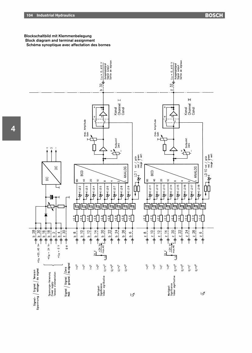
Blockschaltbild mit KlemmenbelegungBlock diagram and terminal assignmentSchéma synoptique avec affectation des bornes
Industrial Hydraulics 105
4
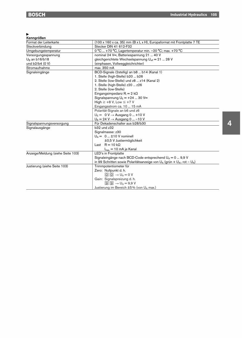
yKenngrößenFormat der Leiterkarte (100 x 160 x ca. 35) mm (B x L x H), Europaformat mit Frontplatte 7 TESteckverbindung Stecker DIN 41 612-F32Umgebungstemperatur 0 °C ... +70 °C, Lagertemperatur min. –20 °C; max. +70 °CVersorgungsspannung nominal 24 V=, Batteriespannung 21 ... 40 VUB an b16/b18 gleichgerichtete Wechselspannung Ueff = 21 ... 28 Vund b2/b4 (0 V) (einphasen, Vollweggleichrichter)Stromaufnahme max. 350 mASignaleingänge BCD-Signale (2stellig) an b8 ... b14 (Kanal 1)
1. Stelle (high-Stelle) b20 ... b262. Stelle (low-Stelle) und z8 ... z14 (Kanal 2)1. Stelle (high-Stelle) z20 ... z262. Stelle (low-Stelle)Eingangsimpedanz Ri = 2 kΩSignalspannung UE = +24 ... 30 V=High ^ +8 V, Low % +7 VEingangsstrom ca. 10 ... 15 mAPolarität-Signale an b6 und z6UE = 20 V R Ausgang 0 ... +10 VUE = 24 V R Ausgang 0 ... –10 V
Signalspannungsversorgung Für Dekadenschalter aus b28/b30Signalausgänge b32 und z32
Signalmasse: z30UA = 0 ... ±10 V nominell
±0,5 V JustiermöglichkeitLast R = 10 kΩ
Imax. = 10 mA je KanalAnzeige/Meldung (siehe Seite 103) LED’s in Frontplatte
Signaleingänge nach BCD-Code entsprechend UA = 0 ... 9,9 Vin 99 Schritten sowie Polaritätsanzeige von UA (grün + UA1 rot – UA)
Justierung (siehe Seite 103) Trimmpotentiometer für Zero: Nullpunkt d. h.
l0 l0 R UA = 0 VGain: Signalspreizung d. h.
l9 l9 R UA = 9,9 VJustierung im Bereich ±5% (von UA max.)
106 Industrial Hydraulics
4
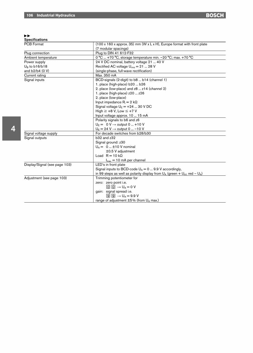
yySpecificationsPCB Format (100 x 160 x approx. 35) mm (W x L x H), Europe format with front plate
(7 modular spacings)Plug connection Plug to DIN 41 612-F32Ambient temperature 0 °C ... +70 °C, storage temperature min. –20 °C; max. +70 °CPower supply 24 V DC nominal, battery voltage 21 ... 40 VUB to b16/b18 Rectified AC voltage Urms = 21 ... 28 Vand b2/b4 (0 V) (single-phase, full-wave rectification)Current rating Max. 350 mASignal inputs BCD-signals (2-digit) to b8 ... b14 (channel 1)
1. place (high-place) b20 ... b262. place (low-place) and z8 ... z14 (channel 2)1. place (high-place) z20 ... z262. place (low-place) Input impedance Ri = 2 kΩSignal voltage UE = +24 ... 30 V DCHigh ^ +8 V, Low % +7 VInput voltage approx. 10 ... 15 mAPolarity signals to b6 and z6UE = 20 V R output 0 ... +10 VUE = 24 V R output 0 ... –10 V
Signal voltage supply For decade switches from b28/b30Signal outputs b32 and z32
Signal ground: z30UA = 0 ... ±10 V nominal
±0.5 V adjustmentLoad R = 10 kΩ
Imax. = 10 mA per channelDisplay/Signal (see page 103) LED’s in front plate
Signal inputs to BCD-code UA = 0 ... 9.9 V accordingly,in 99 steps as well as polarity display from UA (green + UA1 red – UA)
Adjustment (see page 103) Trimming potentiometer for zero: zero point i.e.
l0 l0 R UA = 0 Vgain: signal spread i.e.
l9 l9 R UA = 9.9 Vrange of adjustment ±5% (from UA max.)
Industrial Hydraulics 107
4
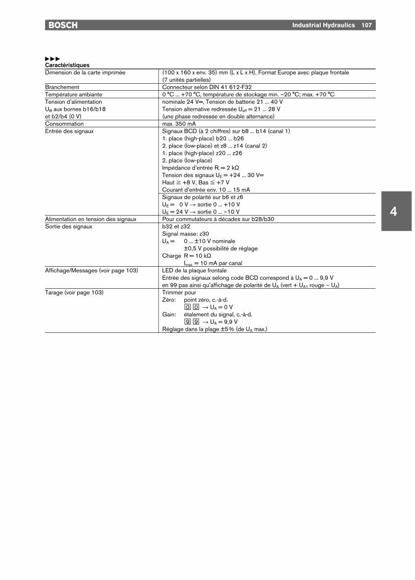
yyyCaractéristiquesDimension de la carte imprimée (100 x 160 x env. 35) mm (L x L x H), Format Europe avec plaque frontale
(7 unités partielles)Branchement Connecteur selon DIN 41 612-F32Température ambiante 0 °C ... +70 °C, température de stockage min. –20 °C; max. +70 °CTension d’alimentation nominale 24 V=, Tension de batterie 21 ... 40 VUB aux bornes b16/b18 Tension alternative redressée Ueff = 21 ... 28 Vet b2/b4 (0 V) (une phase redressée en double alternance)Consommation max. 350 mAEntrée des signaux Signaux BCD (à 2 chiffres) sur b8 ... b14 (canal 1)
1. place (high-place) b20 ... b262. place (low-place) et z8 ... z14 (canal 2)1. place (high-place) z20 ... z262. place (low-place) Impédance d’entrée Ri = 2 kΩTension des signaux UE = +24 ... 30 V=Haut ^ +8 V, Bas % +7 VCourant d’entrée env. 10 ... 15 mASignaux de polarité sur b6 et z6UE = 20 V R sortie 0 ... +10 VUE = 24 V R sortie 0 ... –10 V
Alimentation en tension des signaux Pour commutateurs à décades sur b28/b30Sortie des signaux b32 et z32
Signal masse: z30UA = 0 ... ±10 V nominale
±0,5 V possibilité de réglageCharge R = 10 kΩ
Imax. = 10 mA par canalAffichage/Messages (voir page 103) LED de la plaque frontale
Entrée des signaux selong code BCD correspond à UA = 0 ... 9,9 Ven 99 pas ainsi qu’affichage de polarité de UA (vert + UA1 rouge – UA)
Tarage (voir page 103) Trimmer pourZéro: point zéro, c.-à-d.
l0 l0 R UA = 0 VGain: étalement du signal, c.-à-d.
l9 l9 R UA = 9,9 VRéglage dans la plage ±5% (de UA max.)
4
108 Industrial Hydraulics
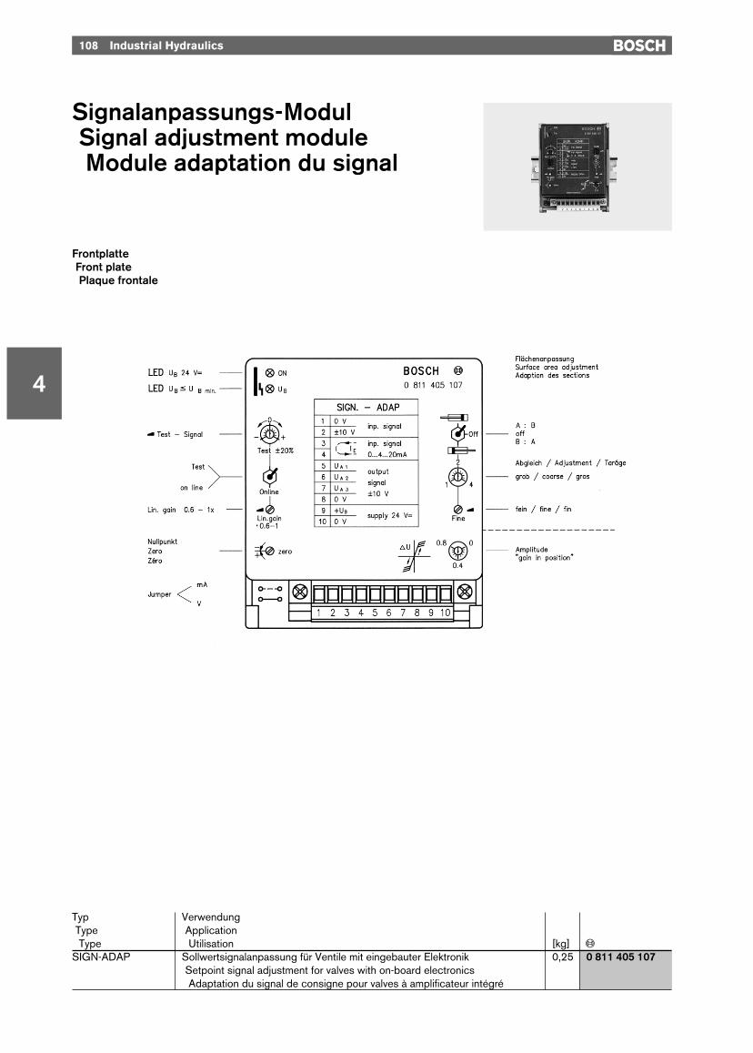
Signalanpassungs-ModulSignal adjustment moduleModule adaptation du signal
FrontplatteFront platePlaque frontale
Typ VerwendungType ApplicationType Utilisation [kg] «
SIGN-ADAP Sollwertsignalanpassung für Ventile mit eingebauter Elektronik 0,25 0 811 405 107Setpoint signal adjustment for valves with on-board electronicsAdaptation du signal de consigne pour valves à amplificateur intégré
Industrial Hydraulics 109
4
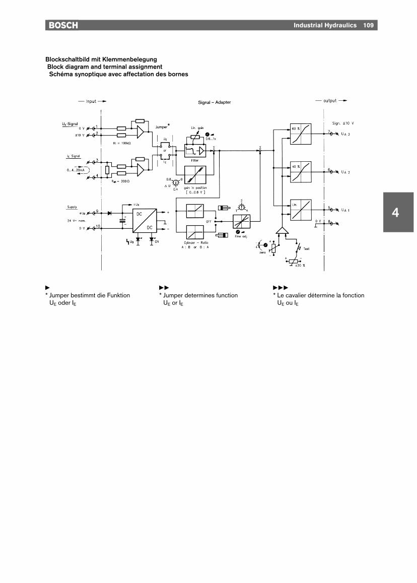
Blockschaltbild mit KlemmenbelegungBlock diagram and terminal assignmentSchéma synoptique avec affectation des bornes
y* Jumper bestimmt die Funktion
UE oder IE
yy* Jumper determines function
UE or IE
yyy* Le cavalier détermine la fonction
UE ou IE

ySignal-(Interface)-Modul– Für Regelventile mit eingebauter
Elektronik:– Kennlinie Linear– Kennlinie Knick 60%– Kennlinie Knick 40%
– Signalanpassung für Differential-Zylinder
– Ventil Nullpunktabgleich– Test-mode (Man. ±20%)– Signalspreizung (Lin. gain)– Eingangssignal: Volt/mA.
yySignal (interface) module– For servo solenoid valves with
on-board electronics:– Performance curve
Linear– Performance curve
Dual gain 60%– Performance curve
Dual gain 40%– Signal adjustment for differential
cylinders– Valve zero adjustment– Test mode (man. ±20%)– Signal spread (lin. gain)– Input signal: volts/mA.
yyyModule (interface) de signaux– Pour servo-distributeurs avec
amplificateur intégré:– Courbe caractéristique
linéaire– Courbe caractéristique
Brisée 60%– Courbe caractéristique
Brisée 40%– Adaptation du signal pour vérins
différentiels– Tarage du zéro valve– Mode de test (man. ±20%)– Etalement du signal (gain lin.)– Signal d’entrée: volts/mA.
110 Industrial Hydraulics
4
SystemschemaSystem layoutSchéma du système

Industrial Hydraulics 111
4
yKenngrößenFormat/Bauform (86 x 110 x 95) mm/ModulBefestigung/Anschluß DIN-Schiene/Stecker + KlemmenTemperaturbereich 0 ... 70 °C Lager: –20 ... +70 °CVersorgungsspannung UB = 24 Vnom, Batt.: 21 ... 40 V=
Einphasen-Vollweg: 21 ... 28 V=eff
Stromaufnahme ca. 0,1 ASignal-Input UE ±10 V, DifferenzverstärkerVolt oder mA Ri = 100 kΩ
IE (0) ... 4–20 mA Rsh = 200 ΩSignal-Output ±10 V UA1 R Ventile mit linearer Kennlinie
UA2 R Ventile mit Knick (40%)UA3 R Ventile mit Knick (60%)
Sonstiges Testmode-Schalter fürman.-control ±20% UA Sign.
yySpecificationsFormat/design (86 x 110 x 95) mm/moduleFastening/connection DIN rail/plug + terminalsTemperature range 0 ... 70 °C storage: –20 ... +70 °CPower supply UB = 24 Vnom/Batt.: 21 ... 40 V DC
Single-phase full wave: 21 ... 28 V DCeff
Current rating approx. 0.1 ASignal input UE ±10 V, difference amplifierVolts or mA Ri = 100 kΩ
IE (0) ... 4–20 mA Rsh = 200 ΩSignal output ±10 V UA1 R valves with linear performance curve
UA2 R valves with dual gain (40%)UA3 R valves with dual gain (60%)
Misc. Test-mode switches forman. control ±20% UA Signal
yyyCaractéristiquesFormat/construction (86 x 110 x 95) mm/moduleFixation/raccordement Rail DIN/connecteur + bornesPlage de températures 0 ... 70 °C stockage: –20 ... +70 °CTension d’alimentation UB = 24 Vnom, batt.: 21 ... 40 V=
une phase redressée en double alternance: 21 ... 28 V=eff
Consommation env. 0,1 AEntrée de signaux UE ±10 V, amplificateur différencevolts ou mA Ri = 100 kΩ
IE (0) ... 4–20 mA Rsh = 200 ΩSortie de signaux ±10 V UA1 R valves à caractéristique linéaire
UA2 R valves à caractéristique brisée (40%)UA3 R valves à caractéristique brisée (60%)
Divers Commutateur de sélection du mode testpour commande manuelle ±20% sign. UA