Embed Size (px)
Citation preview
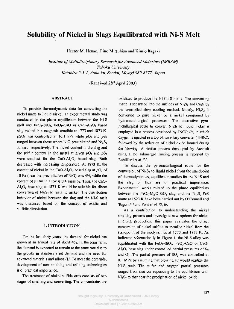
Solubility of Nickel in Slags Equilibrated with Ni-S Melt
Hector M. Henao , Hino Mi t suh isa and K imio Itagaki
Institute of Multidisciplinary Research for Advanced Materials (1MRAM) Tohoku University
Katahira 2-1-1, Aoba-ku, Sendai, Miyagi 980-8577, Japan
(Rece ived 28 , h Apri l 2003)
ABSTRACT
To provide thermodynamic data for converting the nickel matte to liquid nickel, an experimental study was conducted in the phase equilibrium between the Ni-S melt and Fe0^-Si02 , FeO, rCaO or Ca0-Al 2 0 3 based slag melted in a magnesia crucible at 1773 and 1873 K. pS02 was controlled at 10.1 kPa while p02 and pS2
ranged between those where NiO precipitated and Ni3S2
formed, respectively. The nickel content in the slag and the sulfur content in the metal at given p02 and pS2
were smallest for the Ca0-Al 2 0 3 based slag. Both decreased with increasing temperature. At 1873 K, the content of nickel in the Ca0-Al 2 0 3 based slag at p02 of 10 Pa (near the precipitation of NiO) was 4%, while the content of sulfur in alloy is 0.4 mass %. Thus, the CaO-A1203 base slag at 1873 Κ would be suitable for direct converting of Ni3S2 to metallic nickel. The distribution behavior of nickel between the slag and the Ni-S melt was discussed based on the concept of oxidic and sulfidic dissolution.
1. INTRODUCTION
For the last forty years, the demand for nickel has grown at an annual rate of about 4%. In the long term, the demand is expected to remain at the same rate due to the growth in stainless steel demand and the need for advanced materials and alloys /I / . To meet the demands, development of new smelting and refining technologies is of practical importance.
The treatment of nickel sulfide ores consists of two stages of smelting and converting. The concentrates are
oxidized to produce the Ni-Cu-S matte. The converting matte is separated into the sulfides of Ni3S2 and Cu2S by the controlled slow cooling method. Mostly, Ni3S2 is converted to pure nickel or a nickel compound by hydrometallurgical processes. The alternative pyro-metallurgical route to convert Ni3S2 to liquid nickel is employed in a process developed by INCO ill, in which oxygen is injected in a top blown rotary converter (TBRC), followed by the reduction of nickel oxide foimed during the blowing. A similar process developed by Ausmelt using a top submerged lancing process is reported by Robilliard et al. /3/.
To discuss the pyrometallurgical route for the conversion of Ni3S2 to liquid nickel from the standpoint of thermodynamics, equilibrium studies for the Ni-S and the slag or flux are of practical importance. Experimental works related to the phase equilibrium between the F e 0 , r M g 0 - S i 0 2 slag and the Ni3S2-FeS matte at 1523 Κ have been carried out by O'Connell and Toguri /4/ and Font et al. 15, 61.
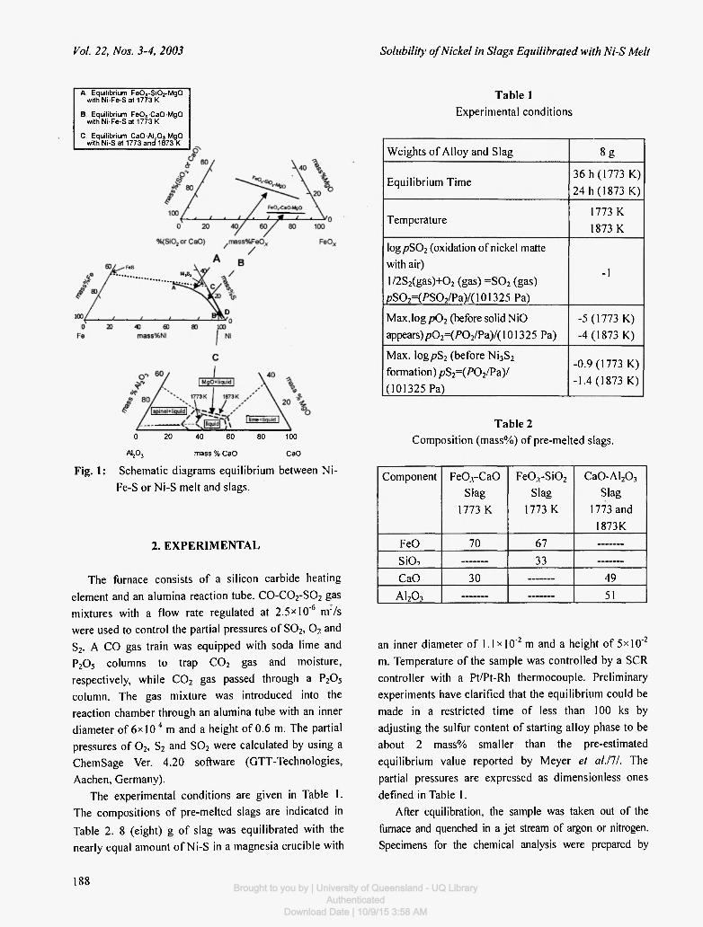
As a contribution to understanding the nickel smelting process and investigate new options for nickel smelting production, this paper evaluates the direct conversion of nickel sulfide to metallic nickel from the standpoint of thermodynamics at 1773 and 1873 K. As indicated schematically in Figure 1, the Ni-S alloy was equilibrated with the Fe0A-Si02 , FeO, r CaO or CaO-A1203 base slag under controlled partial pressures of S2
and 0 2 . The partial pressure of S 0 2 was controlled at 0.1 MPa by assuming that blowing air would oxidize the Ni-S melt. The sulfur and oxygen partial pressures ranged from that corresponding to the equilibrium with Ni3S2 to that near the precipitation of nickel oxide.
187 Brought to you by | University of Queensland - UQ Library
AuthenticatedDownload Date | 10/9/15 3:58 AM
Vol. 22, Nos. 3-4, 2003 Solubility of Nickel in Slags Equilibrated with Ni-S Melt
A: Equilibrium FeO x -S iOrMgO withNi-Fe-S at 1773 Κ
Β: Equilibrium FeO x-CaO-MgO with Ni-Fe-S at 1773 Κ
C: Equilibrium Ca0-A l 20 3 -Mg0 with Ni-S at 1773 and 1873 Κ
0 20 40 60 80 100
A l ^ mass % CaO CaO
Fig. 1: Schematic diagrams equilibrium between Ni-Fe-S or Ni-S melt and slags.
2. EXPERIMENTAL
The furnace consists of a silicon carbide heating element and an alumina reaction tube. C 0 - C 0 2 - S 0 2 gas mixtures with a flow rate regulated at 2.5x10"6 n r / s were used to control the partial pressures of S0 2 , 0 2 and S2. A CO gas train was equipped with soda lime and P 2 0 5 columns to trap C 0 2 gas and moisture, respectively, while C 0 2 gas passed through a P 2 0 5
column. The gas mixture was introduced into the reaction chamber through an alumina tube with an inner diameter of 6 x 1 0 4 m and a height of 0.6 m. The partial pressures of 0 2 , S2 and S 0 2 were calculated by using a ChemSage Ver. 4.20 software (GTT-Technologies, Aachen, Germany).
The experimental conditions are given in Table 1. The compositions of pre-melted slags are indicated in Table 2. 8 (eight) g of slag was equilibrated with the nearly equal amount of Ni-S in a magnesia crucible with
Table 1 Experimental conditions
Weights of Alloy and Slag 8 g
Equilibrium Time 36 h (1773 K) 24 h (1873 K)
Temperature 1773 Κ 1873 Κ
log p S 0 2 (oxidation of nickel matte with air)
l /2S2(gas)+02 (gas) = S 0 2 (gas) ,e>S02=(/>S02/Pa)/(101325 Pa)
-1
Max.log p02 (before solid NiO appears )p0 2 =(P0 2 /Pa) / ( 101325 Pa)
-5 (1773 Κ) -4 (1873 Κ)
Max. iogpS2 (before Ni3S2
formation) pS 2 =(P0 2 /Pa) / (101325 Pa)
-0 .9(1773 Κ)
-1.4 (1873 Κ)
Table 2 Composition (mass%) of pre-melted slags.
Component
FeO
SiO, CaO
Α Ι Α ,
FeO, r CaO Slag
1773 Κ
70
30
F e 0 . r S i 0 2
Slag 1773 Κ
67
33
Ca0-Al 2 0 3
Slag 1773 and
1873K
49
51
an inner diameter of l . lxlO"2 m and a height of 5χ10"2
m. Temperature of the sample was controlled by a SCR controller with a Pt/Pt-Rh thermocouple. Preliminary experiments have clarified that the equilibrium could be made in a restricted time of less than 100 ks by adjusting the sulfur content of starting alloy phase to be about 2 mass% smaller than the pre-estimated equilibrium value reported by Meyer et al.lll. The partial pressures are expressed as dimensionless ones defined in Table 1.
After equilibration, the sample was taken out of the fiimace and quenched in a jet stream of argon or nitrogen. Specimens for the chemical analysis were prepared by
188 Brought to you by | University of Queensland - UQ LibraryAuthenticated
Download Date | 10/9/15 3:58 AM
Ilecio Μ. Henao et αϊ High Temperature Materials and Processes
cutting the alloy sample into small pieces and grinding the slag sample, followed by thoroughly removing the small alloy particles included in the slag with a magnet. The slag and alloy specimens were analyzed by the inductively coupled plasma spectrometry (ICP) and by the conventional methods of chemical analysis with volumetric titration and gravity measurements. The total sulfur content in the slag specimen was determined by a combustion-infrared spectrometer (EMIA-580, HOR1BA Co, Ltd., Kyoto, JAPAN).
(a) 1773 Κ log P o ,
3. RESULTS
3.1 Al loy P h a s e
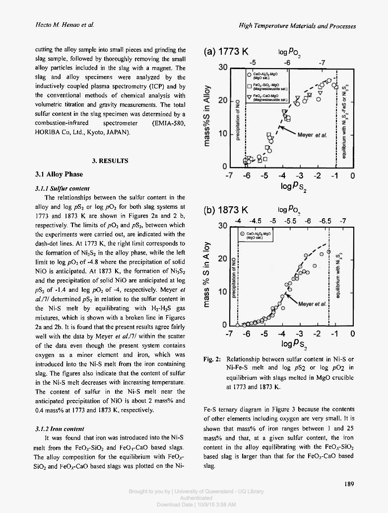
3.1.1 Sulfur content The relationships between the sulfur content in the
alloy and log pS2 or log pö2 for both slag systems at 1773 and 1873 Κ are shown in Figures 2a and 2 b, respectively. The limits of p02 and pS2, between which the experiments were carried out, are indicated with the dash-dot lines. At 1773 K, the right limit corresponds to the formation of Ni3S2 in the alloy phase, while the left limit to log p02 of -4.8 where the precipitation of solid NiO is anticipated. At 1873 K, the formation of Ni3S2
and the precipitation of solid NiO are anticipated at log pS2 of -1.4 and log p02 of -4, respectively. Meyer et al.m determined pS2 in relation to the sulfur content in the Ni-S melt by equilibrating with H2-H2S gas mixtures, which is shown with a broken line in Figures 2a and 2b. It is found that the present results agree fairly well with the data by Meyer et al.lll within the scatter of the data even though the present system contains oxygen as a minor element and iron, which was introduced into the Ni-S melt from the iron containing slag. The figures also indicate that the content of sulfur in the Ni-S melt decreases with increasing temperature. The content of sulfur in the Ni-S melt near the anticipated precipitation of NiO is about 2 mass% and 0.4 mass% at 1773 and 1873 K, respectively.
3.1.2 Iron content It was found that iron was introduced into the Ni-S
melt from the Fe0^-Si0 2 and F e O r C a O based slags. The alloy composition for the equilibrium with FeO^-Si0 2 and FeO^-CaO based slags was plotted on the Ni-
(b) 1873 Κ
-5 -4 -3 -2 -1 l o g P s 2
log P o ,
> ο
<
c
CO
(Λ CO 05 Ε
-7 -6 -5 -4 -3 l o g P s ,
-4 -4 .5 -5 -5 .5 -6 -6 .5 -7
1 0
Fig. 2: Relationship between sulfur content in Ni-S or Ni-Fe-S melt and log pS2 or log p Ö 2 in equilibrium with slags melted in MgO crucible at 1773 and 1873 K.
Fe-S ternary diagram in Figure 3 because the contents of other elements including oxygen are very small. It is shown that mass% of iron ranges between 1 and 25 mass% and that, at a given sulfur content, the iron content in the alloy equilibrating with the Fe0 iV-Si02
based slag is larger than that for the FeOA-CaO based slag.
189 Brought to you by | University of Queensland - UQ Library
AuthenticatedDownload Date | 10/9/15 3:58 AM

Vol. 22, Nos. 3-4, 2003 Solubility of Nickel in Slags Equilibrated with Ni-S Melt
T h e compos i t i on o f C a 0 - A l 2 0 3 based s l ag is shown
in F igure 5 on the M g 0 - N i 0 - ( A I 2 0 3 + C a 0 ) ternary
d iagram because the m a s s % rat io of C a 0 / A l 2 0 3 is
constant . It is indicated in the f igure that the solubil i ty
of M g O in the s lag dec reases when the solubi l i ty of N i O
increases . It is appa ren t that the M g O solubil i ty
increases with increas ing t empera tu re . T h e present
exper imenta l resul ts ag ree with those repor ted in a
re fe rence /10 / when the con ten t of M g O is ex t rapola ted
at the axis o f M g 0 - ( C a 0 + A l 2 0 3 ) .
4 0
Fe
Fig . 3 : C o m p o s i t i o n o f N i - F e - S mel t s equi l ibra ted
with s lags in M g O cruc ib le at 1773 K.
3.2 Slag Phase
T h e s lag compos i t i ons for the F e 0 A - S i 0 2 - M g 0 or
F e O . r C a O - M g O s lag are r ep roduced in Figure 4 on the
A - B - C ternary d i ag ram with a m a s s % scale where A
co r r e sponds to M g O , Β to S i 0 2 or C a O and C to
( F e O . f f N i O ) . T h e solubi l i ty in the F e 0 . v - S i 0 2 based s lag
is larger than that in the F e O , r C a O based slag. Despi te
the p resence of N i O , the l iquidus line in the F e 0 . r S i 0 2
based s lag is s imi lar to that repor ted by M u a n and
Osborn /8 / , which is very c lose to a tie line c o m b i n i n g
be tween FeO and M g 0 S i 0 2 . It is repor ted by Johnson
and M u a n / 9 / that the solubi l i ty of M g O in the FeO^-
C a O - M g O slag in coex i s t ence with the sol id
magnesiowiis t i te c h a n g e s very little with the F c O *
content . Th i s is in a c c o r d a n c e with the presen t result .
0 ' 2 0
(SiO, or CaO)
40 6 0 80 100
mass%(FeOx+ NiO) (FeOx+NiO)
Fig . 4 : C o m p o s i t i o n of s lags equ i l ib ra ted with N i - F e - S
al loy mel ted in M g O cruc ib le at 1773 K.
100,
mass%(Ca0+AI203)
10
mass% NiO NiO-
Fig. 5 : C o m p o s i t i o n o f C a 0 - A l 2 0 3 based s lag
equi l ibra ted with N i - S al loy mel ted in M g O
cruc ib le at 1773 and 1873K.
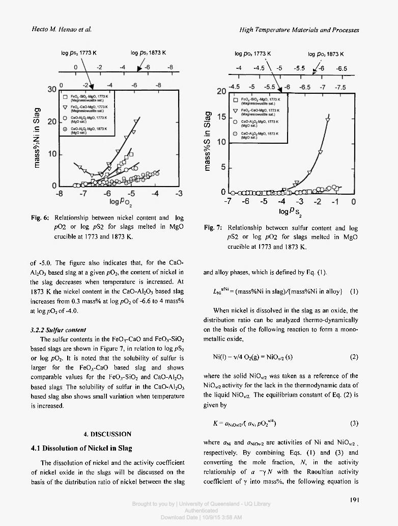
3.2.1 Nickel content T h e nickel content in t he s lags equi l ib ra ted with the
N i - S mel t is plot ted in Figure 6, in relat ion to l o g / ? 0 2 o r
log pS2. It is noted that the C a 0 - A l 2 0 3 and F e 0 , r S i 0 2
based s lags represent lower and h igher solubi l i ty o f
nickel in the slag, respec t ive ly . T h e solubi l i ty o f nickel
in the F e 0 , v - S i 0 2 based s lag increases wi th increas ing
log p02 f r o m 0.5 m a s s % at log p02 o f -7 .3 to 10 m a s s %
at log p02 o f -5 .0 . Whi le , that in the F e O A - C a O based
slag dec reases in a region o f lower o x y g e n pressure
f rom 6 m a s s % at log p02 o f -7.1 to 4 m a s s % at log p02
of about -6 .5 , then, r e m a r k a b l y increases in the range of
h igher log p02 and b e c o m e s 2 0 m a s s % at log p02 o f -
4 .8 . It is shown that the nickel con ten t in the C a 0 - A l 2 0 3
based s lag at 1773 Κ increases with inc reas ing p02 f r om
0.3 m a s s % at log p02 o f -7 .3 to 5 .7 m a s s % at log p02
190
• Fe0j ( -S i0 2 -Mg0 (Magnesiowustites sa t )
V FeOx-CaO-MgO (Magnesiowustites sat.)
60 mass%Ni
^-Fes feline
Brought to you by | University of Queensland - UQ LibraryAuthenticated
Download Date | 10/9/15 3:58 AM
Hecto Μ Henao et al. High Temperature Materials and Processes
log ps2 1773 Κ log ps2 1873 Κ
Ο)
α>
c
ζ oN
V) CO CO Ε
Fig. 6: Relationship between nickel content and log ρθ2 or log pS2 for slags melted in MgO crucible at 1773 and 1873 K.
of -5.0. The figure also indicates that, for the CaO-A1203 based slag at a given p02, the content of nickel in the slag decreases when temperature is increased. At 1873 Κ the nickel content in the Ca0-Al 2 0 3 based slag increases from 0.3 mass% at log p02 of -6.6 to 4 mass% at log p02 of-4.0.
3.2.2 Sulfur content The sulfur contents in the F e O r C a O and F e 0 . r S i 0 2
based slags are shown in Figure 7, in relation to log pS2
or log p02. It is noted that the solubility of sulfur is larger for the FeO, rCaO based slag and shows comparable values for the Fe0.v-Si02 and CaO-AI2Oj based slags The solubility of sulfur in the Ca0-Al 2 0 3
based slag also shows small variation when temperature is increased.
4. DISCUSSION
4.1 Dissolution of Nickel in Slag
The dissolution of nickel and the activity coefficient of nickel oxide in the slags will be discussed on the basis of the distribution ratio of nickel between the slag
log po2 1773 Κ
-4 -4.5 \ -5
log po21873 Κ
5.5 J - 6 -6.5
D) TO
ω
(Λ
(Λ (/) TO Ε
0 k > < D a m 2 0 S D a 5 - 7 - 6 - 5 - 4 - 3
l o g P s 2
Fig. 7: Relationship between sulfur content and log pS2 or log ρθ2 for slags melted in MgO crucible at 1773 and 1873 K.
and alloy phases, which is defined by Eq. (1).
L U iM = (mass%Ni in slag)/{mass%Ni in alloy} (1)
When nickel is dissolved in the slag as an oxide, the distribution ratio can be analyzed thermo-dynamically on the basis of the following reaction to form a mono-metallic oxide,
Ni(l) + v/4 0 2 (g ) = Ni0 v / 2 ( s ) (2)
where the solid NiOv/2 was taken as a reference of the NiOv/2 activity for the lack in the thermodynamic data of the liquid NiOv/2. The equilibrium constant of Eq. (2) is given by
κ - ön.OvM «Ν, p0 2v / 4 ) (3)
where oNi and ^NiOv/2 a r e activities of Ni and NiOv/2 , respectively. By combining Eqs. (1) and (3) and converting the mole fraction, N, in the activity relationship of a =y Ν with the Raoultian activity coefficient of γ into mass%, the following equation is
191 Brought to you by | University of Queensland - UQ LibraryAuthenticated
Download Date | 10/9/15 3:58 AM
Vol. 22, Nos. 3-4, 2003 Solubility of Nicke! in Slags Equilibrated with Ni-S Melt
obtained.
log L n r =v/4log/)02+log [{γΝί}/ (γΝΙΟν/2) ]
+iog [(«τ)/ {«τ}]+ log a: (4)
where, ( ) and { } denote the slag and alloy phases, respectively. nT is the total number of moles in 100g of each phase, which was calculated on the mono-cation base.
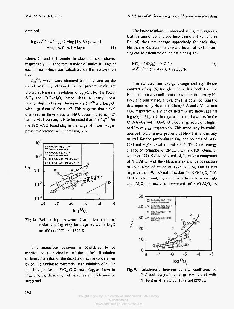
which were obtained from the data on the nickel solubility obtained in the present study, are plotted in Figure 8 in relation to log p02. For the FeO^-Si02 and Ca0-Al203 based slags, a nearly linear relationship is observed between log Z , N i S / N l and log p02
with a gradient of about 1/2. This suggests that nickel dissolves in these slags as NiO, according to eq. (2) with ν =2. However, it is to be noted that the L ^ ^ ' for the FeO;rCaC> based slag in the range of lower oxygen pressure decreases with increasing pö2.
101
1 0
l l io~1
1 0
10"
• 1 I
FeO^-SiOj MgO, 1773 Κ (Magnesiowustite sat.)
—1 1 • •
V FeOx-CaO-MgO, 1773K (Magnesiowustite sat.)
ο CaO-AI-Pj-MgO. 1773 Κ (MgO sat.)
Θ CaO-Aipj-MgO, 1673 Κ (MgO sat.)
V v ^
^ B c P ^ NiO 1
1 1 2
ι I
- 8 -7 -6 -5 logPo,
-4 -3
Fig. 8: Relationship between distribution ratio of nickel and log ρ θ 2 for slags melted in MgO crucible at 1773 and 1873 K.
This anomalous behavior is considered to be ascribed to a mechanism of the nickel dissolution different from that of the dissolution as the oxide given by eq. (2). Owing to extremely large solubility of sulfur in this region for the FeO.v-CaO based slag, as shown in Figure 7, the dissolution of nickel as a sulfide may be suggested.
The linear relationship observed in Figure 8 suggests that the sum of activity coefficient ratio and ηΊ ratio in Eq. (4) does not change appreciably for each slag. Hence, the Raoultian activity coefficient of NiO in each slag can be calculated on the basic of Eq. (5)
Ni(l) + '/202(g) = NiO (s) AG°/(J/mol)= -247750 + 92.52 77K
(5)
The standard free energy change and equilibrium constant of eq. (5) are given in a data book/11/. The Raoultian activity coefficient of nickel in the ternary Ni-Fe-S and binary Ni-S alloys, {yn,}, is obtained from the data reported by Hsieh and Chang /12/ and J.M. Larrain /13/, respectively. The calculated yNi0 are shown against log p02 in Figure 9. In a general trend, the values for the Ca0-Al203 and FeO^-CaO based slags represent higher and lower γΝι0, respectively. This trend may be mainly ascribed to a chemical property of NiO that is relatively neutral for the predominant slag components of basic CaO and MgO as well as acidic Si02 The Gibbs energy change of formation of 2Mg0 Si02 is -18.8 kJ/mol of cation at 1773 Κ /14/. NiO and A1203 make a compound of NiOAI2Q3 with the Gibbs energy change of reaction of -6.9 kJ/mol of cation at 1773 Κ /15/, that is less negative than -9.1 kJ/mol of cation for N i 0 Fe203/16/. On the other hand, the chemical affinity between CaO and A1203 to make a compound of C a 0 AI203 is
Ο z
Fig. 9: Relationship between activity coefficient of NiO and log pC>2 for slags equilibrated with Ni-Fe-S or Ni-S melt at 1773 and 1873 K.
192 Brought to you by | University of Queensland - UQ Library
AuthenticatedDownload Date | 10/9/15 3:58 AM
Hecto Μ. Henao et al.
considered to be very large with the Gibbs energy change of reaction of -16.8 kJ/mol of cation at 1773 Κ /17/. Takeda and Yazawa /18/ suggested that a solution tends to repel the component which has a low affinity with the main components when these have a considerably high affinity to form the stable solution. The observed trend for yNi0 is in concordance with this suggestion.
The experimental results for the solubility of nickel in the FeO,v-CaO based slag in the range of lower oxygen pressure, where log L^^*1 - log pö2 plots deviate from the linear relationship, may be analyzed thermodynamically by combining the oxidic and sulfidic dissolution of nickel in the slag, (mass%Ni)ox
and (mass%Ni)s. According to Nagamori /19/, (mass%Ni)0X and (mass%Ni)s will be given by Eqs. (6) and (7), respectively.
(mass%Ni)0X = A au, /?02"2 /γΝ ι 0 (6)
(mass%Ni)s = Β aNiS (mass%S) (7)
where A and D are constants. aNjS is known from the data reported by Hsieh and Chang /12/ and the content of sulfur in the slag, (mass%S), was obtained in the present study. The present experimental data for the solubility of nickel in the FeCVCaO based slag were analyzed by regression on the basis of Eqs. (6) and (7). It was found that they could be reproduced well when A and Β in eqs. (6) and (7) are 26000 and 6.4, respectively.
4.2 Appl icat ion to Nickel S m e l t i n g
The nickel contents in the alloys equilibrated with the Fe0^-Si0 2 and FeO, rCaO slags (fluxes) in a MgO crucible at 1773 Κ are relatively large at more than 95 mass%, but with considerable amounts of iron, sulfur and oxygen impurities. Thus, when a process of smelting the Ni-S or Ni-Fe-S alloy with the Fe0,v-Si02
and FeCVCaO based slags (fluxes) is considered, a refining process for the metal product will be indispensable. Furthermore, it is to be noted that the content of nickel in the iron slag is considerably large at more than 10 mass%. This means that the loss of nickel in the slag will be substantial in the smelting process. A simple mass balance calculation was made by assuming smelting a matte with 50 mass% of nickel and 25
High Temperature Materials and Processes
mass% of iron to produce a metallic phase with 2 mass% of iron and 2.5 mass% of sulfur and a slag phase with 40 mass% of iron. It is indicated that the losses of nickel in the Fe0A -Si0 2 and FeO^-CaO based slag amount to 12 and 24 mass%, respectively. The loss of nickel would increase with increasing content of iron in the initial matte phase.
It was clarified in the present study that the content of nickel in the slag is not so high in the iron-free CaO-A1203 based slag. Furthermore, the amount of produced slag in the process would be kept small to reduce the loss of nickel in the slag. Thus, the present result suggests that the Ca0-Al 2 0 3 based slag will be more useful for converting the Ni-S melt to liquid nickel. The amounts of impurities such as sulfur and oxygen contained in the alloy equilibrated with the Ca0-Al 2 0 3
based slag can be reduced substantially by increasing the temperature from 1773 to 1873 K. Furthermore, it is to be noted that the content of nickel in the Ca0-Al 2 0 3
based slag is extremely small and decreases with increasing temperature. This means that the loss of nickel in the Ca0-Al 2 0 3 based slag can be kept down at a desired level if the amount of produced slag or used flux in the process is kept small and the process temperature is increased.
5. CONCLUSIONS
The main objective of the present study was to investigate and look for the slag or the flux suitable for direct converting of Ni3S2 to metallic nickel. Thus, the Ni-S alloy was equilibrated with the Fe0.y-Si02, F e 0 . r CaO or Ca0-Al 2 0 3 based slag in a magnesia crucible under controlled partial pressures of S2 and 0 2 . The partial pressure of S 0 2 was controlled at 0.1 MPa by assuming that blowing air would oxidize the Ni-S melt.
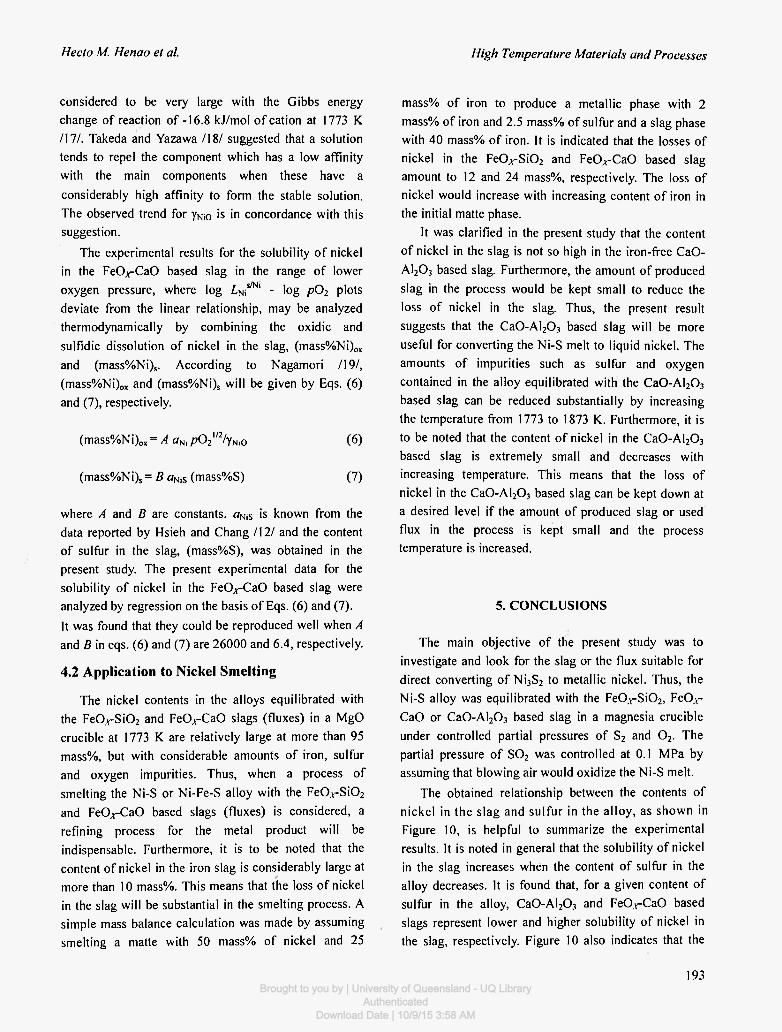
The obtained relationship between the contents of nickel in the slag and su l fur in the alloy, as shown in Figure 10, is helpful to summarize the experimental results. It is noted in general that the solubility of nickel in the slag increases when the content of sulfur in the alloy decreases. It is found that, for a given content of sulfur in the alloy, Ca0-Al 2 0 3 and FeO, rCaO based slags represent lower and higher solubility of nickel in the slag, respectively. Figure 10 also indicates that the
193 Brought to you by | University of Queensland - UQ Library
AuthenticatedDownload Date | 10/9/15 3:58 AM
Vol. 22, Nos. 3-4, 2003 Solubility of Nickel in Slags Equilibrated with Ni-S Melt
mass%S in Alloy
Fig. 10: Relationship between nickel content in slag and sulfur content in alloy for Ni-S melt equilibrated with slag.
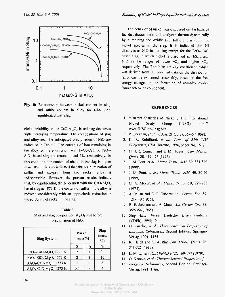
nickel solubility in the CaO-A^O^ based slag decreases with increasing temperature. The compositions of slag and alloy near the anticipated precipitation of NiO are indicated in Table 3. The contents of iron remaining in the alloy for the equilibrium with Fe0.v-Ca0 or FeO, r
Si02 based slag are around 1 and 2%, respectively. In this condition, the content of nickel in the slag is higher than 10%. It is also indicated that further elimination of sulfur and oxygen from the nickel alloy is indispensable. However, the present results indicate that, by equilibrating the Ni-S melt with the Ca0-Al 2 0 3
based slag at 1873 K, the content of sulfur in the alloy is reduced considerably with an appreciable reduction in the solubility of nickel in the slag.
Table 3 Melt and slag composition at pö2 just before
precipitation of NiO.
The behavior of nickel was discussed on the basis of the distribution ratio and analyzed thermo-dynamically by combining the oxidic and sulfidic dissolution of nickel species in the slag. It is indicated that Ni dissolves as NiO in the slag except for the FeO, rCaO based slag, in which nickel is dissolved as NiS0 6 6 and NiO in the ranges of lower p02 and higher p02, respectively. The Raoultian activity coefficient, which was derived from the obtained data on the distribution ratio, can be explained reasonably, based on the free energy changes in the formation of complex oxides from each oxide component.
REFERENCES
1. "Current Statistics of Nickel", The International Nickel Study Group (INSG), http:// www.INSG.org/insg.htm
2. P. Queneau, et αϊ: J. Met. 21 (July), 35-45 (1969).
3. K. R. Robilliard, el al\ Proc. of 25th CIM Conference, CIM, Toronto, 1994, paper No. 16. 2.
4. G. J. O'Connell and J. M. Toguri: Can. Metall. Quart. 35,419-426 (1996).
5. J. M. Font, et al.: Mater. Trans., JIM. 39, 834-840 (1998).
6. J. M. Font, et al: Mater. Trans., JIM. 40, 20-26 (1999).
7. G. A. Meyer, et al.: Metall. Trans. 6B, 229-235 (1975).
8. A. Muan and E. F Osbom: Am. Ceram. Soc. 39, 121-140(1956).
9. R. E. Johnson and A. Muan: Am. Ceram. Soc. 48, 359-364 (1965).
10. Slag Atlas, Verein Deutscher Eisenhüttenleute (VDEh), 1995; 104.
11. Ο. Knacke, et al.: Thermochemical Properties of Inorganic Substances, Second Edition, Springer-Verlag, 1991; 1455.
12. Κ. Hsieh and Y. Austin: Can. Metall. Quart. 26, 311-327 (1987).
13. L. M. Larrain: CALPHAD 3 (2), 169-177 (1979). 14. O. Knacke, et al.: Thermochemical Properties of 15. Inorganic Substances, Second Edition, Springer-
Verlag, 1991; 1166.
Slag System Nickel
(mass%)
Slag (mass
%) Slag System
S Fe Ni
F e 0 . r C a 0 - M g 0 , 1773 Κ 2 1 20
Fe0 A -Si0 2 -Mg0, 1773 Κ 2 2 10
AI 2O rCaO-MgO, 1773 Κ 1 - 6
Al 2 0 3 -Ca0-Mg0, 1873 Κ 0.4 - 4
194 Brought to you by | University of Queensland - UQ Library
AuthenticatedDownload Date | 10/9/15 3:58 AM
Hecto Μ. Henao et al. High Temperature Materials and Processes
16. O. Knacke, et al.: Thermochemical Properties of Inorganic Substances, Second Edition, Springer-Verlag, 1991; 1491.
17. Ο. Knacke, et al.: Thermochemical Properties of Inorganic Substances, Second Edition, Springer-Verlag, 1991; 1486.
18. Ο. Knacke, et al.: Thermochemical Properties of
Inorganic Substances, Second Edition, Springer-Verlag, 1991; 396.
19. Y. Takeda and A. Yazawa: Proc. of Intern. Conf. on Productivity and Technology in the Metallurgical Industries, TMS, Köln, 1989; 227-240.
20. Μ. Nagamori: Metall Trans. 5, 531-538 (1974).
195 Brought to you by | University of Queensland - UQ Library
AuthenticatedDownload Date | 10/9/15 3:58 AM

Brought to you by | University of Queensland - UQ LibraryAuthenticated
Download Date | 10/9/15 3:58 AM