Embed Size (px)
Citation preview
Solutions for Explicit Routing In Internet2 Gigapops and NRNs
Version 1.0 12 August 2002
Brian Daugherty, CSE, CCIE #5879 [email protected]
Khalid Raza, Design Consultant
Larry Dunn, Mgr, Business Development [email protected]
Higher Education and Research Initiatives
Solutions for Explicit Routing Internet2 Gigapops
Copyright Cisco Systems, 2002 Page 2 12-Aug-02
Table of Contents Table of Contents ............................................................................................................................ 2 List of Figures.................................................................................................................................. 2 Overview ......................................................................................................................................... 3 Background..................................................................................................................................... 3 Legacy Strategies for Explicit Routing............................................................................................ 4 An Evolving Solution for Explicit Routing ....................................................................................... 8 Loading Routes into the VRFs...................................................................................................... 11 Using the Interface-Based VRF Model on Memory-Constrained Platforms................................ 13 Extending the Interface-Based VRF Model .................................................................................. 15 Extending Interface-Based VRFs using Logical Connections ..................................................... 16 Extending Interface-Based VRFs using Source-Based VRF-Selection ...................................... 17 Routing Issues with Source-Based VRF-Selection...................................................................... 19 VRF-Selection in Network-Based Solutions ................................................................................. 20
List of Figures Figure 1: Explicit Routing using the Dual Physical Links ............................................................... 5 Figure 2: Explicit Routing using ATM PVCs and Dual Gigapop Routers ..................................... 6 Figure 3: Best-Path Selection at the Customer using ATM PVCs................................................. 7 Figure 4: Directed ISP Selection using ATM PVCs ....................................................................... 8 Figure 5: Explicit Routing using the Interface-Based VRF Model.................................................. 9 Figure 6: Route Distribution in the Interface-Based VRF Model................................................. 11 Figure 7: Explicit Routing using the Interface-Based VRFs with an .......................................... 14 Figure 8: Route Distribution in the Interface-Based VRF with ..................................................... 15 Figure 9: The Interface-Based VRF Model Cannot Support Multiple Policies Per Interface ...... 16 Figure 10: Explicit Routing using the Interface-Based VRF Model with Logical Interfaces ........ 17 Figure 11: Lookups and Potential Packet Paths using Source-Based VRF-Selection ............... 18 Figure 12: Route Distribution in the Source-Selected VRF Model .............................................. 20 Figure 13: VRF-Select Combined with MPLS VPNs.................................................................... 21
Please Note: The graphics in this document make extensive use of color, therefore the use of a color printer to create a hardcopy is strongly recommended to maintain readability.
Solutions for Explicit Routing Internet2 Gigapops
Copyright Cisco Systems, 2002 Page 3 12-Aug-02
Overview In a traditional IP routing model, as a packet traverses a network from its source to its destination each router examines the destination address and - if a route to that destination exists - the packet is forwarded to the router known to be one step closer to the destination. The path taken through a network is controlled by the routing topology, which is in turn built by the Interior (IGP) or Exterior (EGP) gateway protocols such as OSPF, IS-IS, or BGP – protocols that identify and install the shortest path to a given destination in a router’s routing and forwarding tables. Although it is possible to manipulate the metrics used by IGPs and EGPs to identify the shortest or most desirable path to a given destination, such manipulations will result in a routing topology that will be applied to all of the packets traversing the network. Although we can manipulate routing metrics to steer or balance network traffic, these manipulations are not sufficient to provide different paths for different classes of traffic. To provide different – or explicit – routes through a network for different classes of traffic, other mechanisms such as Policy-Based Routing (PBR) can be deployed. PBR overrides the normal destination-based forwarding employed by routers and instead uses a broader set of metrics such as ingress-interface, source and destination addresses, and source and destination ports to make a forwarding decision. PBR mechanisms are reasonably flexible, allowing packet forwarding to specific interfaces and next-hop routers, but they have significant drawbacks as well, including significant burden on the forwarding elements of a router as each packet is examined, significant degradation of forwarding performance, and an insensitivity to the status (up or down) of the egress interface or next-hop router. To address the shortcomings inherent to PBR other solutions have been evolving that rely on the normal hardware-accelerated destination-based forwarding mechanisms but attempt to explicitly route traffic by providing different topological views for different classes of traffic. The evolution and nature of these ‘Explicit Routing’ solutions – especially those deployed in Internet2 Gigapops – are the topic of this whitepaper.
Background
Internet2 is collection of universities and research organizations dedicated to the creation of the next-generation Internet. In their own words:
“Internet2 is a consortium being led by over 216 universities working in partnership with industry and government to develop and deploy advanced network applications and technologies, accelerating the creation of tomorrow's Internet. Internet2 is recreating the partnership among academia, industry and government that fostered today’s Internet in its infancy. The primary goals of Internet2 are to:
• Create a leading edge network capability for the national research community • Enable revolutionary Internet applications
Solutions for Explicit Routing Internet2 Gigapops
Copyright Cisco Systems, 2002 Page 4 12-Aug-02
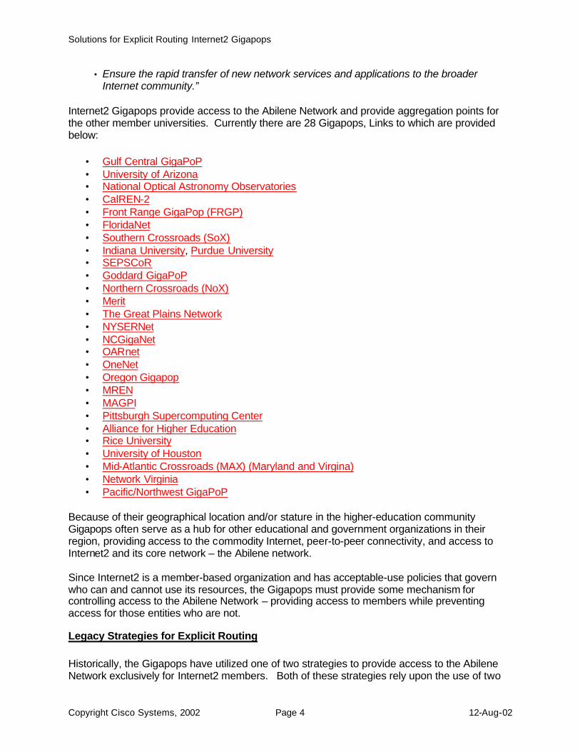
• Ensure the rapid transfer of new network services and applications to the broader Internet community.”
Internet2 Gigapops provide access to the Abilene Network and provide aggregation points for the other member universities. Currently there are 28 Gigapops, Links to which are provided below:
• Gulf Central GigaPoP • University of Arizona • National Optical Astronomy Observatories • CalREN-2 • Front Range GigaPop (FRGP) • FloridaNet • Southern Crossroads (SoX) • Indiana University, Purdue University • SEPSCoR • Goddard GigaPoP • Northern Crossroads (NoX) • Merit • The Great Plains Network • NYSERNet • NCGigaNet • OARnet • OneNet • Oregon Gigapop • MREN • MAGPI • Pittsburgh Supercomputing Center • Alliance for Higher Education • Rice University • University of Houston • Mid-Atlantic Crossroads (MAX) (Maryland and Virgina) • Network Virginia • Pacific/Northwest GigaPoP
Because of their geographical location and/or stature in the higher-education community Gigapops often serve as a hub for other educational and government organizations in their region, providing access to the commodity Internet, peer-to-peer connectivity, and access to Internet2 and its core network – the Abilene network. Since Internet2 is a member-based organization and has acceptable-use policies that govern who can and cannot use its resources, the Gigapops must provide some mechanism for controlling access to the Abilene Network – providing access to members while preventing access for those entities who are not.
Legacy Strategies for Explicit Routing Historically, the Gigapops have utilized one of two strategies to provide access to the Abilene Network exclusively for Internet2 members. Both of these strategies rely upon the use of two
Solutions for Explicit Routing Internet2 Gigapops
Copyright Cisco Systems, 2002 Page 5 12-Aug-02
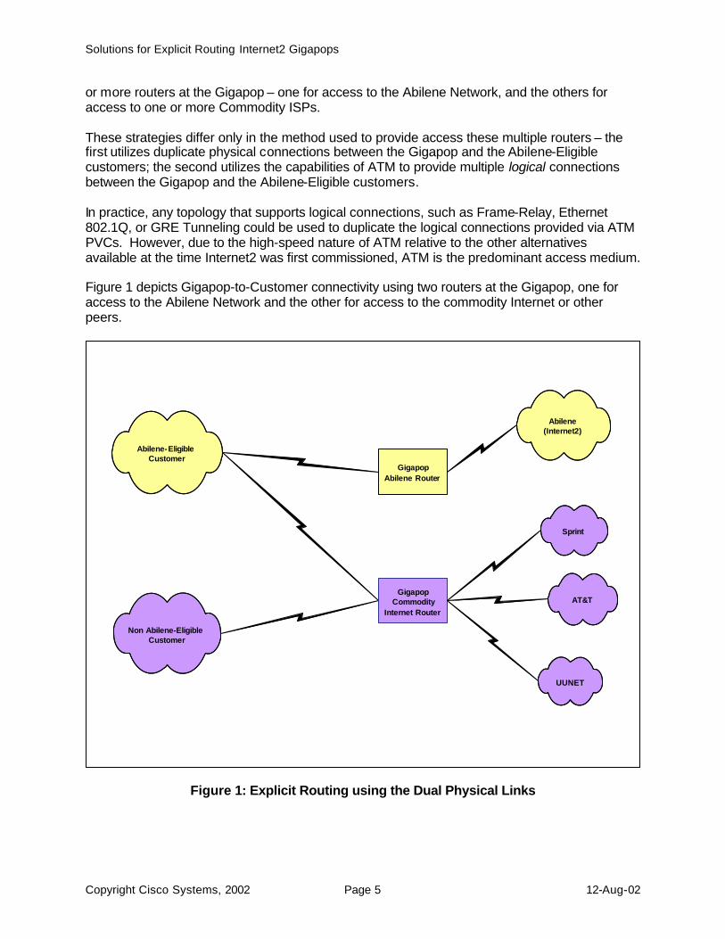
or more routers at the Gigapop – one for access to the Abilene Network, and the others for access to one or more Commodity ISPs. These strategies differ only in the method used to provide access these multiple routers – the first utilizes duplicate physical connections between the Gigapop and the Abilene-Eligible customers; the second utilizes the capabilities of ATM to provide multiple logical connections between the Gigapop and the Abilene-Eligible customers. In practice, any topology that supports logical connections, such as Frame-Relay, Ethernet 802.1Q, or GRE Tunneling could be used to duplicate the logical connections provided via ATM PVCs. However, due to the high-speed nature of ATM relative to the other alternatives available at the time Internet2 was first commissioned, ATM is the predominant access medium. Figure 1 depicts Gigapop-to-Customer connectivity using two routers at the Gigapop, one for access to the Abilene Network and the other for access to the commodity Internet or other peers.
Figure 1: Explicit Routing using the Dual Physical Links
Sprint
Abilene (Internet2)
AT&T
UUNET
Abilene-Eligible Customer
Non Abilene-Eligible Customer
Gigapop Abilene Router
Gigapop Commodity
Internet Router
Solutions for Explicit Routing Internet2 Gigapops
Copyright Cisco Systems, 2002 Page 6 12-Aug-02
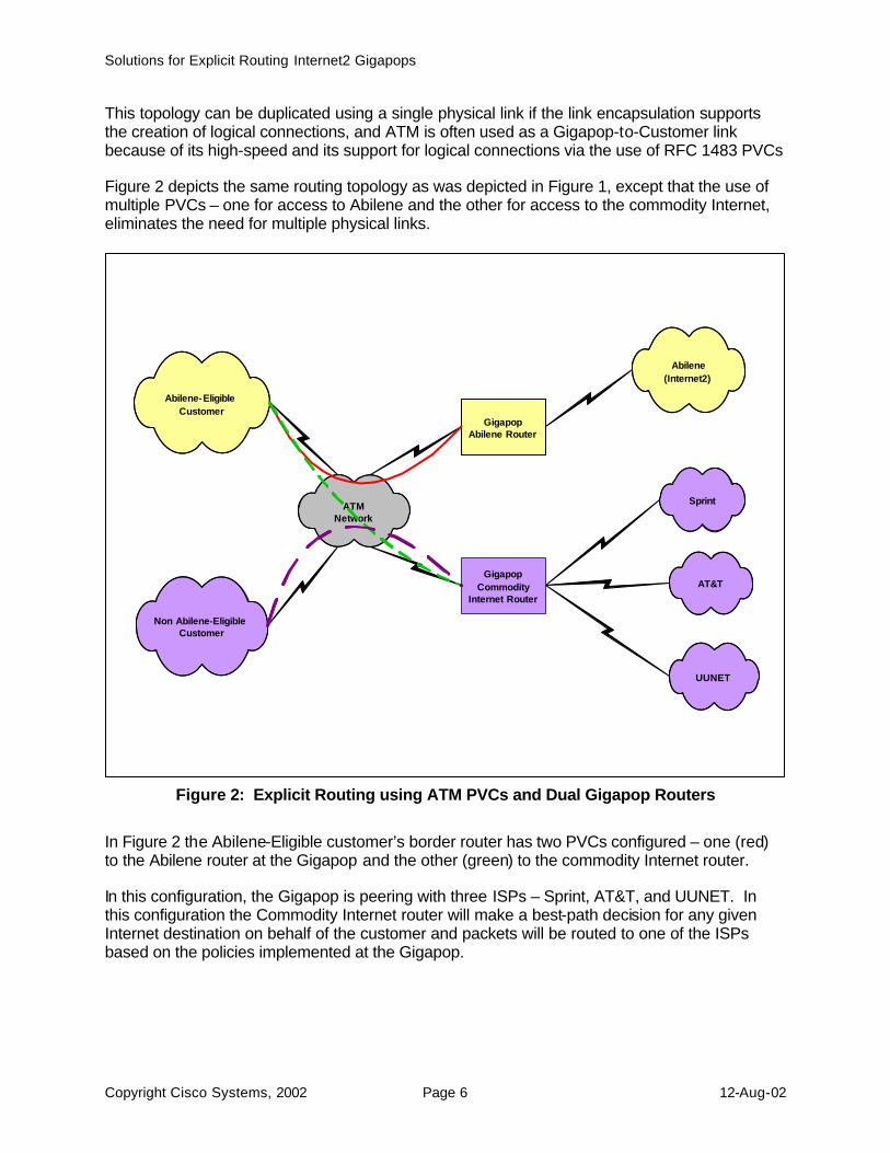
This topology can be duplicated using a single physical link if the link encapsulation supports the creation of logical connections, and ATM is often used as a Gigapop-to-Customer link because of its high-speed and its support for logical connections via the use of RFC 1483 PVCs Figure 2 depicts the same routing topology as was depicted in Figure 1, except that the use of multiple PVCs – one for access to Abilene and the other for access to the commodity Internet, eliminates the need for multiple physical links.
Figure 2: Explicit Routing using ATM PVCs and Dual Gigapop Routers
In Figure 2 the Abilene-Eligible customer’s border router has two PVCs configured – one (red) to the Abilene router at the Gigapop and the other (green) to the commodity Internet router. In this configuration, the Gigapop is peering with three ISPs – Sprint, AT&T, and UUNET. In this configuration the Commodity Internet router will make a best-path decision for any given Internet destination on behalf of the customer and packets will be routed to one of the ISPs based on the policies implemented at the Gigapop.
Sprint
Abilene (Internet2)
AT&T
UUNET
Abilene-Eligible Customer
Non Abilene-Eligible Customer
Gigapop Abilene Router
Gigapop Commodity
Internet Router
ATM Network
Solutions for Explicit Routing Internet2 Gigapops
Copyright Cisco Systems, 2002 Page 7 12-Aug-02
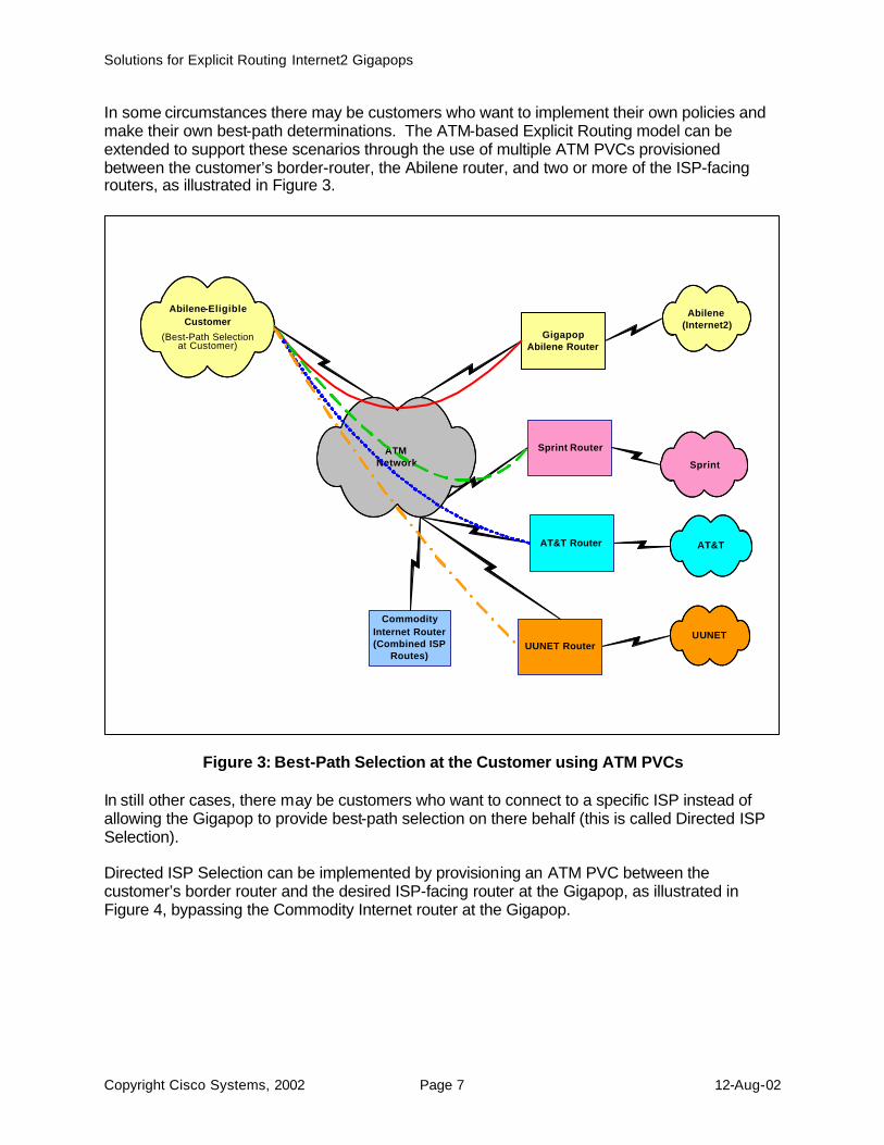
In some circumstances there may be customers who want to implement their own policies and make their own best-path determinations. The ATM-based Explicit Routing model can be extended to support these scenarios through the use of multiple ATM PVCs provisioned between the customer’s border-router, the Abilene router, and two or more of the ISP-facing routers, as illustrated in Figure 3.
Figure 3: Best-Path Selection at the Customer using ATM PVCs
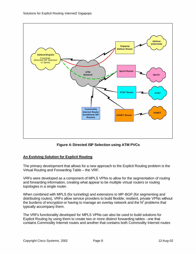
In still other cases, there may be customers who want to connect to a specific ISP instead of allowing the Gigapop to provide best-path selection on there behalf (this is called Directed ISP Selection). Directed ISP Selection can be implemented by provisioning an ATM PVC between the customer’s border router and the desired ISP-facing router at the Gigapop, as illustrated in Figure 4, bypassing the Commodity Internet router at the Gigapop.
Sprint
Abilene (Internet2)
AT&T
UUNET
Abilene-Eligible Customer
(Best-Path Selection at Customer)
Gigapop Abilene Router
Sprint Router ATM Network
AT&T Router
UUNET Router
Commodity Internet Router (Combined ISP
Routes)
Solutions for Explicit Routing Internet2 Gigapops
Copyright Cisco Systems, 2002 Page 8 12-Aug-02
Figure 4: Directed ISP Selection using ATM PVCs
An Evolving Solution for Explicit Routing The primary development that allows for a new approach to the Explicit Routing problem is the Virtual Routing and Forwarding Table – the VRF. VRFs were developed as a component of MPLS VPNs to allow for the segmentation of routing and forwarding information, creating what appear to be multiple virtual routers or routing topologies in a single router. When combined with MPLS (for tunneling) and extensions to MP-BGP (for segmenting and distributing routes), VRFs allow service providers to build flexible, resilient, private VPNs without the burdens of encryption or having to manage an overlay network and the N2 problems that typically accompany them. The VRFs functionality developed for MPLS VPNs can also be used to build solutions for Explicit Routing by using them to create two or more distinct forwarding tables - one that contains Commodity Internet routes and another that contains both Commodity Internet routes
Sprint
Abilene (Internet2)
AT&T
UUNET
Abilene-Eligible Customer
(Directed ISP Selection to Sprint)
Gigapop Abilene Router
Sprint Router ATM Network
AT&T Router
UUNET Router
Commodity Internet Router (Combined ISP
Routes)
Solutions for Explicit Routing Internet2 Gigapops
Copyright Cisco Systems, 2002 Page 9 12-Aug-02
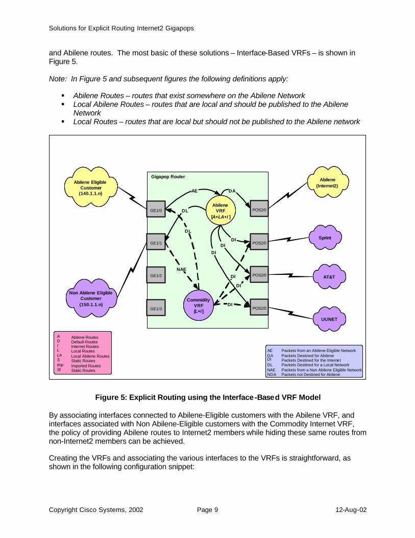
and Abilene routes. The most basic of these solutions – Interface-Based VRFs – is shown in Figure 5. Note: In Figure 5 and subsequent figures the following definitions apply: § Abilene Routes – routes that exist somewhere on the Abilene Network § Local Abilene Routes – routes that are local and should be published to the Abilene
Network § Local Routes – routes that are local but should not be published to the Abilene network
Figure 5: Explicit Routing using the Interface-Based VRF Model By associating interfaces connected to Abilene-Eligible customers with the Abilene VRF, and interfaces associated with Non Abilene-Eligible customers with the Commodity Internet VRF, the policy of providing Abilene routes to Internet2 members while hiding these same routes from non-Internet2 members can be achieved. Creating the VRFs and associating the various interfaces to the VRFs is straightforward, as shown in the following configuration snippet:
Sprint
Abilene (Internet2)
AT&T
UUNET
Abilene Eligible Customer
(140.1.1.n)
Non Abilene Eligible Customer (150.1.1.n)
Gigapop Router
POS2/0
POS2/0
POS2/0
POS2/0
GE1/0
GE1/1
GE1/2
GE1/3
DL
DI
Abilene VRF
[ A+LA+I ]
Commidity VRF [ L+I ]
DI
DI
DA AE
DI DI
DI
DL
NAE
A Abilene Routes D Default Routes I Internet Routes L Local Routes LA Local Abilene Routes S Static Routes Imp Imported Routes St Static Routes
AE Packets from an Abilene Eligible Network DA Packets Destined for Abilene DI Packets Destined for the Internet DL Packets Destined for a Local Network NAE Packets from a Non Abilene Eligible Network NDA Packets not Destined for Abilene
Solutions for Explicit Routing Internet2 Gigapops
Copyright Cisco Systems, 2002 Page 10 12-Aug-02
! Define VPN Routing instance Abilene ip vrf Abilene rd 100:1 ! ! Define VPN Routing instance Commodity ip vrf Commodity rd 100:2 ! ! Abilene-Eligible Customer interface ge1/0 ip address 140.1.1.1 255.255.255.0 ip vrf forwarding Abilene ! ! Non Abilene-Eligible Customer interface ge1/1 ip address 150.1.1.1 255.255.255.0 ip vrf forwarding Commodity ! ! Abilene-Facing Interface interface pos2/0 ip address 130.1.1.1 255.255.255.0 ip vrf forwarding Abilene ! ! ISP-Facing Interface (Sprint) interface pos1/0/1 ip address 100.1.1.1 255.255.255.0 ip vrf forwarding Commodity ! ISP-Facing Interface (AT&T) interface pos2/1 ip address 101.1.1.1 255.255.255.0 ip vrf forwarding Commodity ! ! ISP-Facing Interface (UUNET) interface pos2/1 ip address 102.1.1.1 255.255.255.0 ip vrf forwarding Commodity In the Interface-Based VRFs Model there are no requirements for multiple physical links or multiple logical connections between the Gigapop and the customer, so the Gigapops and customers can now migrate away from WAN technologies such as HDLC, Frame-Relay, and ATM to begin to take advantage of the higher speeds and efficiencies of OC-12 to OC-192 POS, GE, and 10GE The platform requirements for providing this solution are as follows:
• A 12000-Series router with IOS 12.0(22)S or later. • Maximum DRAM to support multiple VRFs and the maximum number or routes.
There are approximately 105K Internet routes today, so to support one Commodity VRF and one Abilene VRF, the platform needs to support >220K routes in total – two sets of Internet routes, ~5000 Abilene routes, and ~5000 Local routes.
Solutions for Explicit Routing Internet2 Gigapops
Copyright Cisco Systems, 2002 Page 11 12-Aug-02
The model shown in Figure 5 is extremely simple. It is possible to extend this model to any arbitrary level of complexity as long as the constraints on the total number of routes and VRFs are not exceeded.
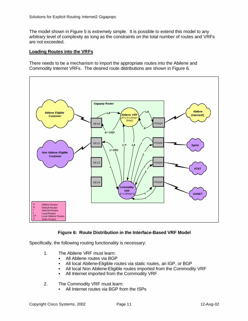
Loading Routes into the VRFs There needs to be a mechanism to import the appropriate routes into the Abilene and Commodity Internet VRFs. The desired route distributions are shown in Figure 6.
Figure 6: Route Distribution in the Interface-Based VRF Model Specifically, the following routing functionality is necessary:
1. The Abilene VRF must learn: § All Abilene routes via BGP § All local Abilene-Eligible routes via static routes, an IGP, or BGP § All local Non Abilene-Eligible routes imported from the Commodity VRF § All Internet imported from the Commodity VRF
2. The Commodity VRF must learn: § All Internet routes via BGP from the ISPs
Gigapop Router
Sprint
Abilene (Internet2)
AT&T
UUNET
Abilene Eligible Customer
Non Abilene Eligible Customer
POS2/0
A + ( I / D )
LA
A
LA
I
L
I
L
POS2/0
POS2/0
POS2/0
GE1/0
GE1/1
GE1/2
GE1/3
L
LA L + I
L I
L + ( I / D )
Abilene VRF [ A+LA+L(Imp)+
I(Imp) ]
Commidity VRF
[ L+LA(Imp)+I]
A Abilene Routes D Default Routes I Internet Routes L Local Routes LA Local Abilene Routes S Static Routes
Solutions for Explicit Routing Internet2 Gigapops
Copyright Cisco Systems, 2002 Page 12 12-Aug-02
§ All local Non Abilene-Eligible routes via static routes, an IGP, or BGP § All local Abilene-Eligible routes imported from the Abilene VRF
There are several mechanisms available to load routes into a VRF – they can be statically defined, dynamically learned via BGP, OSPF, or RIP, or imported from other VRFs as a function of BGP and BGP community attributes. Routes can be statically added to a VRF using as using the following syntax: ip route vrf <VRF-name> <ip address> <ip mask> <interface> <next-hop ip address> Learning routes via a dynamic routing protocol requires the use of address-families within routing protocols that support VRFs – BGP, RIP, and OSPF today. The syntax to allow routes to be learned via BGP and added to the Abilene VRF would appear as follows: ! Configure BGP sessions ! router bgp 1 no synchronization ! ! Deactivate default IPv4 advertisements ! no bgp default ipv4-activate ! ! Define BGP PE-CE session for VRF Abilene ! address-family ipv4 unicast vrf Abilene neighbor 140.1.1.2 remote-as 65535 neighbor 140.1.1.2 update-source GE1/0 neighbor 140.1.1.2 activate no auto-summary exit-address-family Note: Refer to the appropriate IOS MPLS VPN Software Configuration Guide for a complete description of the tasks necessary to configure dynamic routing protocols for use with VRFs. Routes can also be imported into VRFs based on the configuration of Route-Descriptors and Route-Targets. When a VRF is created it is given a unique Route-Descriptor that is associated with each installed route. For example: ip vrf Abilene rd 1:100 ! ip vrf Commodity rd 1:200 Routes in a VRF can be exported to other VRFs, and conversely, routes can be imported from other VRFs. These actions are controlled by the following syntax: ip vrf Abilene rd 1:100 route-target export 1:100 route-target import 1:200
Solutions for Explicit Routing Internet2 Gigapops
Copyright Cisco Systems, 2002 Page 13 12-Aug-02
ip vrf Commodity rd 1:200 route-target export 1:200 route-target import 1:100 This syntax will cause routes learned in either VRF (via both static entries and dynamic routing protocols) to be imported into the other VRF. It is not valid to simply import the contents of the Abilene VRF into the Commodity Internet VRF (by importing route-targets 1:100). To do so would install all of the Abilene routes in both tables and render the use of two VRFs pointless. Instead, it is necessary to utilize import-maps to identify which routes originating with route-descriptor 1:100 should be imported. For example ip vrf Commodity rd 1:200 route-target export 1:200 route-target import 1:100 import map vrf2_import route-map vrf2_import permit 10 match ip address 1 access-list 1 permit 140.1.1.0 0.0.0.255 As shown, by extending the functionality of BGP, RIP, and OSPF with the VRF functions described above, it is possible to create the routing relationships described in Figure 6:
Using the Interface-Based VRF Model on Memory-Constrained Platforms The Interface-Based VRF model requires the use of at least two VRFs, each of which must carry the full Internet routing table. However, if not configured with an adequate amount of memory, some platforms may not be able to support the number of routes required to implement two large VRFs. In these cases is still possible to use the Interface-Based VRF model under by using an external loopback connection between two interfaces. This configuration requires a full-set of Internet routes only in the Commodity Internet VRF Figure 7 illustrates the packet flow realized by this configuration:
Solutions for Explicit Routing Internet2 Gigapops
Copyright Cisco Systems, 2002 Page 14 12-Aug-02
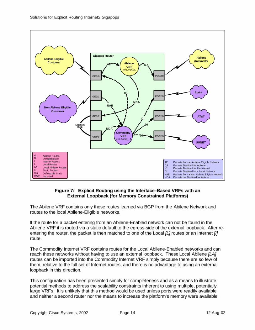
Figure 7: Explicit Routing using the Interface-Based VRFs with an External Loopback (for Memory Constrained Platforms)
The Abilene VRF contains only those routes learned via BGP from the Abilene Network and routes to the local Abilene-Eligible networks. If the route for a packet entering from an Abilene-Enabled network can not be found in the Abilene VRF it is routed via a static default to the egress-side of the external loopback. After re-entering the router, the packet is then matched to one of the Local [L] routes or an Internet [I] route. The Commodity Internet VRF contains routes for the Local Abilene-Enabled networks and can reach these networks without having to use an external loopback. These Local Abilene [LA] routes can be imported into the Commodity Internet VRF simply because there are so few of them, relative to the full set of Internet routes, and there is no advantage to using an external loopback in this direction. This configuration has been presented simply for completeness and as a means to illustrate potential methods to address the scalability constraints inherent to using multiple, potentially large VRFs. It is unlikely that this method would be used unless ports were readily available and neither a second router nor the means to increase the platform’s memory were available.
Sprint
Abilene (Internet2)
AT&T
UUNET
Abilene Eligible Customer
Non Abilene Eligible Customer
Gigapop Router
POS2/0
POS2/0
POS2/0
POS2/0
GE1/0
GE1/1
GE1/2
GE1/3
Loopback Cable
DL
DI DI
DI
DA AE
NDA
AE Packets from an Abilene Eligible Network DA Packets Destined for Abilene DI Packets Destined for the Internet DL Packets Destined for a Local Network NAE Packets from a Non Abilene Eligible Network NDA Packets not Destined for Abilene
NAE
NDA
Abilene VRF
[A+LA+D(St) ]
Commidity VRF
[ L+LA(Imp)+I ]
A Abilene Routes D Default Routes I Internet Routes L Local Routes LA Local Abilene Routes S Static Routes (St) Defined via Static (Imp) Imported
Solutions for Explicit Routing Internet2 Gigapops
Copyright Cisco Systems, 2002 Page 15 12-Aug-02
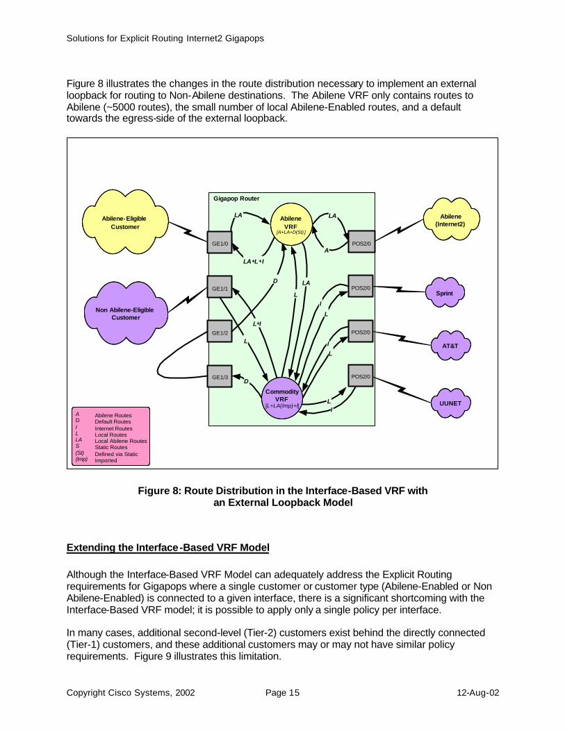
Figure 8 illustrates the changes in the route distribution necessary to implement an external loopback for routing to Non-Abilene destinations. The Abilene VRF only contains routes to Abilene (~5000 routes), the small number of local Abilene-Enabled routes, and a default towards the egress-side of the external loopback.
Figure 8: Route Distribution in the Interface-Based VRF with an External Loopback Model
Extending the Interface-Based VRF Model Although the Interface-Based VRF Model can adequately address the Explicit Routing requirements for Gigapops where a single customer or customer type (Abilene-Enabled or Non Abilene-Enabled) is connected to a given interface, there is a significant shortcoming with the Interface-Based VRF model; it is possible to apply only a single policy per interface. In many cases, additional second-level (Tier-2) customers exist behind the directly connected (Tier-1) customers, and these additional customers may or may not have similar policy requirements. Figure 9 illustrates this limitation.
Gigapop Router
Sprint
Abilene (Internet2)
AT&T
UUNET
Abilene-Eligible Customer
Non Abilene-Eligible Customer
POS2/0
LA + L + I
LA
A
LA
I
L I
L
POS2/0
POS2/0
POS2/0
GE1/0
GE1/1
GE1/2
GE1/3
L
LA L
L I
L + I
D
D
Abilene VRF
[A+LA+D(St) ]
Commodity VRF
[ L+LA(Imp)+I ] A Abilene Routes D Default Routes I Internet Routes L Local Routes LA Local Abilene Routes S Static Routes (St) Defined via Static (Imp) Imported

Solutions for Explicit Routing Internet2 Gigapops
Copyright Cisco Systems, 2002 Page 16 12-Aug-02
Figure 9: The Interface-Based VRF Model Cannot Support Multiple Policies Per Interface
Extending Interface-Based VRFs using Logical Connections There are two categories of solutions under consideration to address this issue; one relies on the use of logical connections or tunnels to extend the Interface-Based VRF model and the other relies on a developing feature called Source-Based VRF-Selection. The first solution relies upon updated mechanisms (relative to ATM) to create logical connections between the customers and the Gigapop. Since VRFs can be associated with both physical and sub-interfaces, it’s possible to extend the Interface-Based VRF model to address the multiple-policies-per-interface scenario illustrated above As long as the physical link encapsulation supports logical interfaces – frame-relay encapsulation over POS and 802.1Q over GE being of most interest here – it is possible to extend the Interface-Based VRF model through a Tier-1 customer, and thereby extend a different policy to one or more Tier-2 customers.
Sprint
Abilene (Internet2)
AT&T
UUNET
Abilene Eligible Customer
Non Abilene Eligible Customer
Gigapop Router
POS2/0
POS2/0
POS2/0
POS2/0
GE1/0
GE1/1
GE1/2
GE1/3
Non Abilene Eligible
Customer
Abilene Eligible Customer X
X
DL
DI
Abilene VRF [ A+L(Imp)+LA+I
(Imp) ]
Commidity VRF
[ L+LA(Imp)+I ]
DI
DI
DA AE
DI DI
DI
DL
NAE
A Abilene Routes D Default Routes I Internet Routes L Local Routes LA Local Abilene Routes S Static Routes (St) Defined via Static (Imp) Imported
AE Packets from an Abilene Eligible Network DA Packets Destined for Abilene DI Packets Destined for the Internet DL Packets Destined for a Local Network NAE Packets from a Non Abilene Eligible Network NDA Packets not Destined for Abilene
Solutions for Explicit Routing Internet2 Gigapops
Copyright Cisco Systems, 2002 Page 17 12-Aug-02
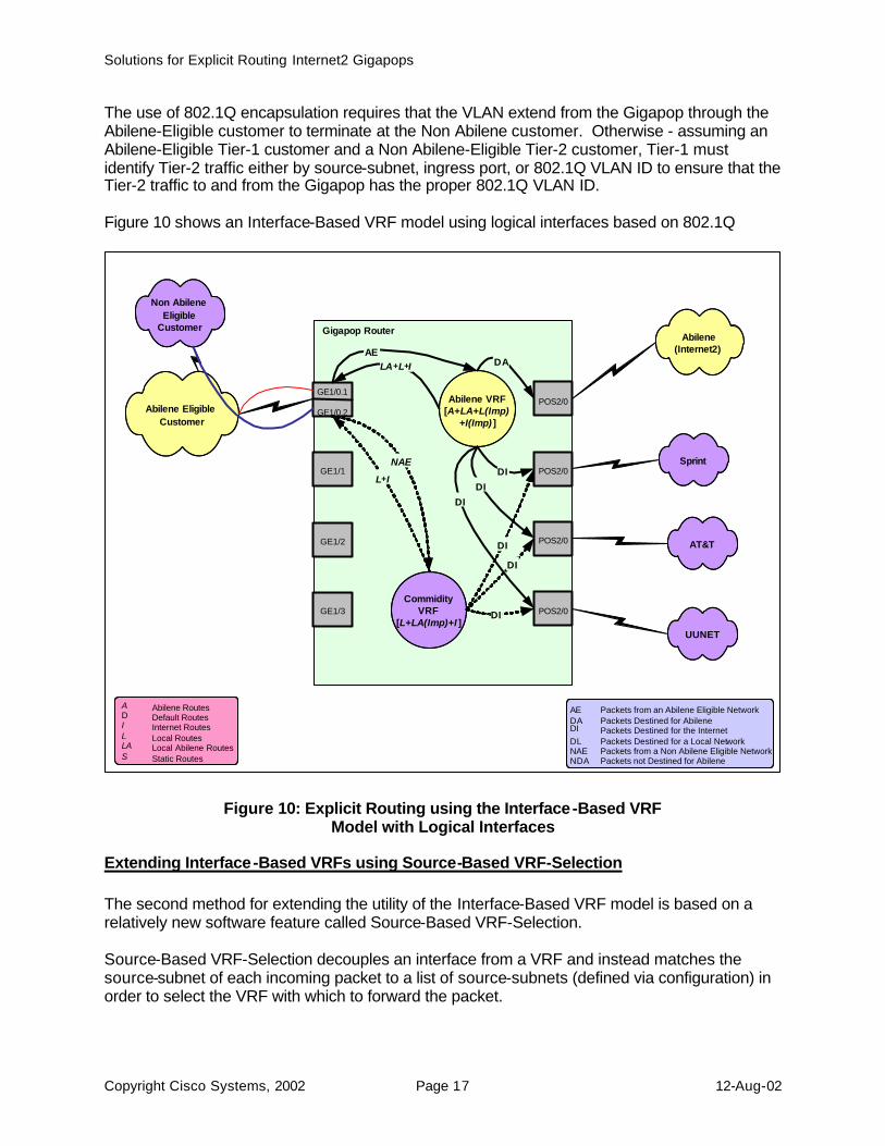
The use of 802.1Q encapsulation requires that the VLAN extend from the Gigapop through the Abilene-Eligible customer to terminate at the Non Abilene customer. Otherwise - assuming an Abilene-Eligible Tier-1 customer and a Non Abilene-Eligible Tier-2 customer, Tier-1 must identify Tier-2 traffic either by source-subnet, ingress port, or 802.1Q VLAN ID to ensure that the Tier-2 traffic to and from the Gigapop has the proper 802.1Q VLAN ID. Figure 10 shows an Interface-Based VRF model using logical interfaces based on 802.1Q
Figure 10: Explicit Routing using the Interface-Based VRF Model with Logical Interfaces
Extending Interface-Based VRFs using Source-Based VRF-Selection The second method for extending the utility of the Interface-Based VRF model is based on a relatively new software feature called Source-Based VRF-Selection. Source-Based VRF-Selection decouples an interface from a VRF and instead matches the source-subnet of each incoming packet to a list of source-subnets (defined via configuration) in order to select the VRF with which to forward the packet.
Sprint
Abilene (Internet2)
AT&T
UUNET
Gigapop Router
POS2/0
POS2/0
POS2/0
POS2/0
GE1/0.1 GE1/0.2
GE1/1
GE1/2
GE1/3
DI
Abilene VRF [ A+LA+L(Imp)
+I(Imp) ]
Commidity VRF
[ L+LA(Imp)+I ]
DI
DI
DA AE
DI DI
DI
A Abilene Routes D Default Routes I Internet Routes L Local Routes LA Local Abilene Routes S Static Routes
AE Packets from an Abilene Eligible Network DA Packets Destined for Abilene DI Packets Destined for the Internet DL Packets Destined for a Local Network NAE Packets from a Non Abilene Eligible Network NDA Packets not Destined for Abilene
Abilene Eligible Customer
Non Abilene Eligible
Customer
LA + L + I
NAE L + I
Solutions for Explicit Routing Internet2 Gigapops
Copyright Cisco Systems, 2002 Page 18 12-Aug-02
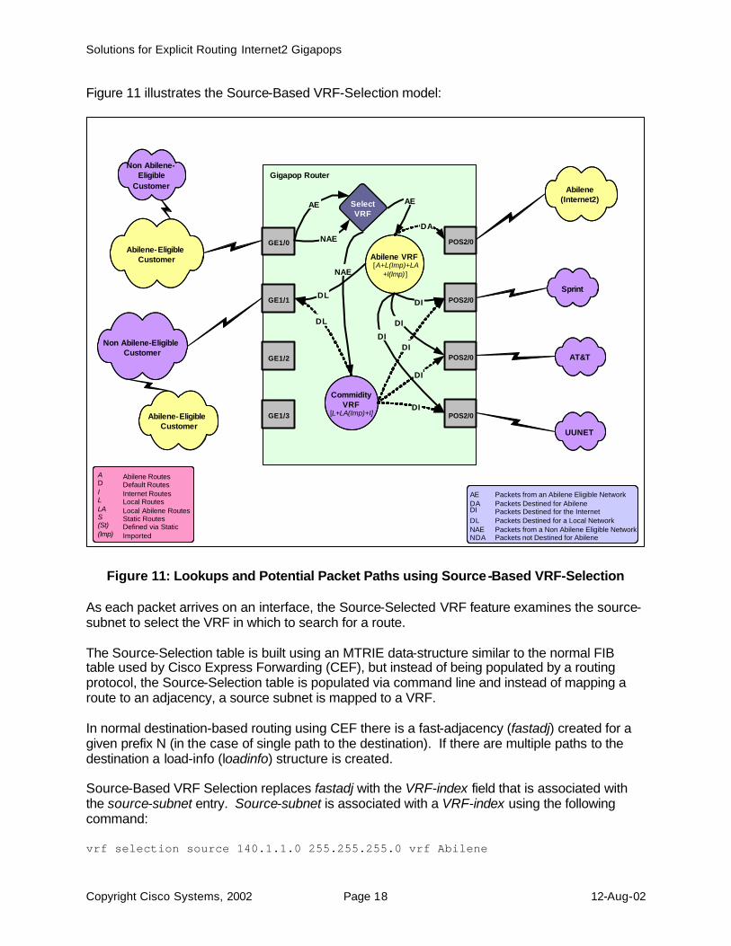
Figure 11 illustrates the Source-Based VRF-Selection model:
Figure 11: Lookups and Potential Packet Paths using Source-Based VRF-Selection As each packet arrives on an interface, the Source-Selected VRF feature examines the source-subnet to select the VRF in which to search for a route. The Source-Selection table is built using an MTRIE data-structure similar to the normal FIB table used by Cisco Express Forwarding (CEF), but instead of being populated by a routing protocol, the Source-Selection table is populated via command line and instead of mapping a route to an adjacency, a source subnet is mapped to a VRF. In normal destination-based routing using CEF there is a fast-adjacency (fastadj) created for a given prefix N (in the case of single path to the destination). If there are multiple paths to the destination a load-info (loadinfo) structure is created. Source-Based VRF Selection replaces fastadj with the VRF-index field that is associated with the source-subnet entry. Source-subnet is associated with a VRF-index using the following command: vrf selection source 140.1.1.0 255.255.255.0 vrf Abilene
Abilene-Eligible Customer
Non Abilene- Eligible
Customer
Sprint
Abilene (Internet2)
AT&T
UUNET
Abilene-Eligible Customer
Non Abilene-Eligible Customer
Gigapop Router
POS2/0
POS2/0
POS2/0
POS2/0
GE1/0
GE1/1
GE1/2
GE1/3
Select VRF
DL
DI
Abilene VRF [ A+L(Imp)+LA
+I(Imp) ]
Commidity VRF
[ L+LA(Imp)+I]
DI
DI
DA AE AE
NAE
NAE
DI DI
DI
DL
A Abilene Routes D Default Routes I Internet Routes L Local Routes LA Local Abilene Routes S Static Routes (St) Defined via Static (Imp) Imported
AE Packets from an Abilene Eligible Network DA Packets Destined for Abilene DI Packets Destined for the Internet DL Packets Destined for a Local Network NAE Packets from a Non Abilene Eligible Network NDA Packets not Destined for Abilene
Solutions for Explicit Routing Internet2 Gigapops
Copyright Cisco Systems, 2002 Page 19 12-Aug-02
vrf selection source 141.1.1.0 255.0.0.0 vrf Commodity The vrf selection source global command is used to specify the source address from which the packet originated, the mask is the subnet mask of the desired subnet, and the VRF name is the VRF with which to associate the source-subnet. In the example above, any packets sourced from subnet 140.1.1.0/24 will be forwarded based on the contents of VRF Abilene, while packets sourced from 141.1.1.0/25 will be forwarded based on the contents of VRF Commodity. Besides the global vrf selection source command that associates a source-subnet with a VRF, the interface command ip vrf select source is configured on the incoming interface to inform the router that the source-subnet should be used to select the VRF with which to forward the packet.
Routing Issues with Source-Based VRF-Selection When using Interface-Based VRFs the relevant interfaces are automatically inserted into the VRF and can be used to forward packets on the return path. Routes to the networks accessible via the VRF-connected interfaces are learned via VRF-enabled routing protocols such as BGP, RIP, OSPF, and VRF static routes. When using Source-Selected VRFs, however, this interface-to-VRF association is broken, so we need another mechanism – ip vrf receive <vrf> – to place the desired interface into the VRF. (The other mechanisms for populating a VRF with routes such as VRF-associated interfaces, BGP, static routes, and route-importation continue to apply when using Source-Selected VRFs.) The interface command ip vrf receive <vrf> tells the router into which VRF (or VRFs) the interface should be inserted. For example: interface GE1/0 ip vrf select source ip vrf receive Abilene ip vrf receive Commodity ip address 140.1.1.1 255.255.255.0 interface GE1/1 ip vrf select source ip vrf receive Abilene ip vrf receive Commodity ip address 150.1.1.1 255.255.255.0 This configuration ensures that the routing is end to end and packet on the return-path of a conversation started on an interface configured for Source-Selected VRFs can be routed properly towards the sender. The interface command ip vrf receive is used to place the interfaces GE1/0 and GE1/1 (both of which provide access to both Abilene-Enabled and Non Abilene-Enabled entities) into both the Abilene and Commodity VRFs. This provides proper routing between local Abilene-Enabled and Non Abilene-Enabled entities and eliminates the need to import Local [L] and
Solutions for Explicit Routing Internet2 Gigapops
Copyright Cisco Systems, 2002 Page 20 12-Aug-02
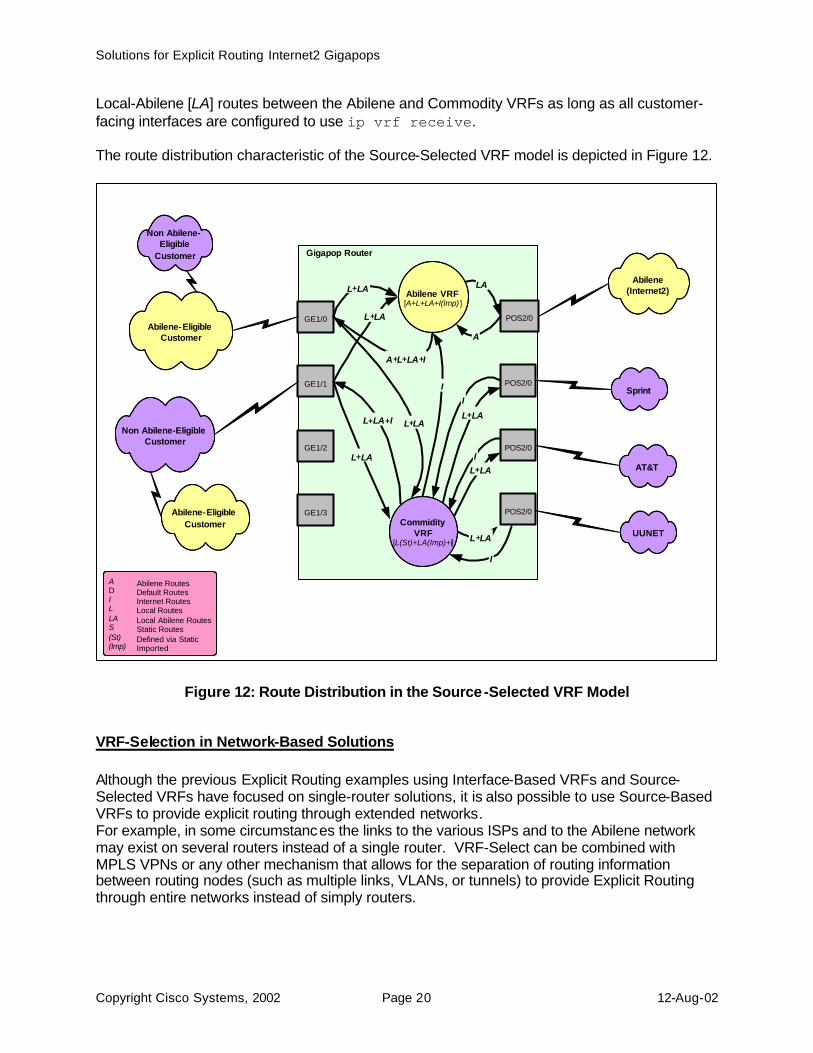
Local-Abilene [LA] routes between the Abilene and Commodity VRFs as long as all customer-facing interfaces are configured to use ip vrf receive. The route distribution characteristic of the Source-Selected VRF model is depicted in Figure 12.
Figure 12: Route Distribution in the Source-Selected VRF Model
VRF-Selection in Network-Based Solutions Although the previous Explicit Routing examples using Interface-Based VRFs and Source-Selected VRFs have focused on single-router solutions, it is also possible to use Source-Based VRFs to provide explicit routing through extended networks. For example, in some circumstances the links to the various ISPs and to the Abilene network may exist on several routers instead of a single router. VRF-Select can be combined with MPLS VPNs or any other mechanism that allows for the separation of routing information between routing nodes (such as multiple links, VLANs, or tunnels) to provide Explicit Routing through entire networks instead of simply routers.
Gigapop Router
Sprint
Abilene (Internet2)
AT&T
UUNET
POS2/0 A
LA
I
L + LA I
L + LA
POS2/0
POS2/0
POS2/0
GE1/0
GE1/1
GE1/2
GE1/3
L + LA L + LA I
L + LA + I
Abilene VRF [ A+L+LA+I(Imp) ]
Commidity VRF
[ L(St)+LA(Imp)+I ]
L + LA
A Abilene Routes D Default Routes I Internet Routes L Local Routes LA Local Abilene Routes S Static Routes (St) Defined via Static (Imp) Imported
Abilene-Eligible Customer
Non Abilene- Eligible
Customer
Abilene-Eligible Customer
Non Abilene-Eligible Customer
L + LA
A + L + LA + I
L + LA
I
Solutions for Explicit Routing Internet2 Gigapops
Copyright Cisco Systems, 2002 Page 21 12-Aug-02
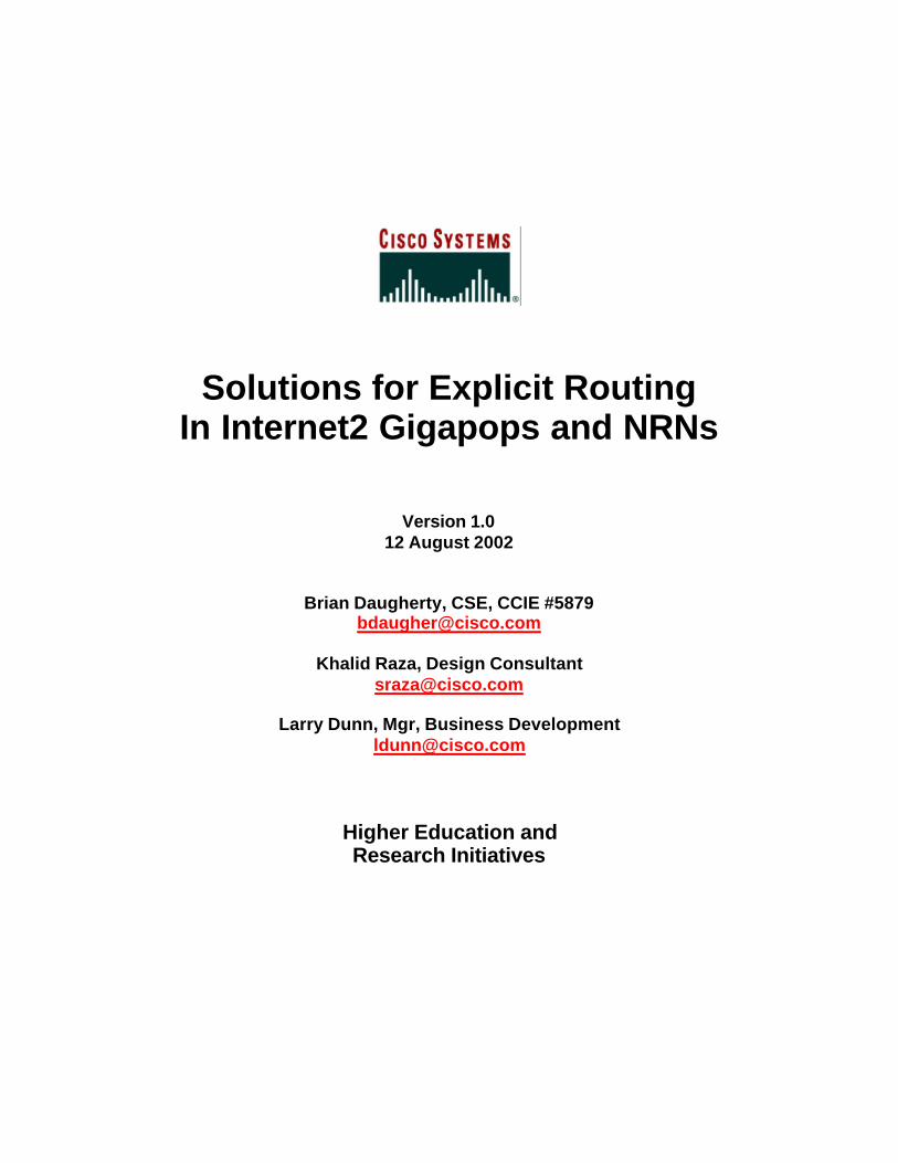
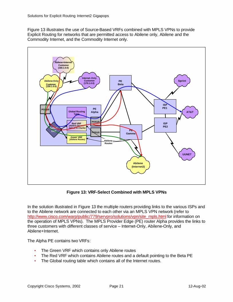
Figure 13 illustrates the use of Source-Based VRFs combined with MPLS VPNs to provide Explicit Routing for networks that are permitted access to Abilene only, Abilene and the Commodity Internet, and the Commodity Internet only.
Figure 13: VRF-Select Combined with MPLS VPNs In the solution illustrated in Figure 13 the multiple routers providing links to the various ISPs and to the Abilene network are connected to each other via an MPLS VPN network (refer to http://www.cisco.com/warp/public/779/servpro/solutions/vpn/site_mpls.html for information on the operation of MPLS VPNs). The MPLS Provider Edge (PE) router Alpha provides the links to three customers with different classes of service – Internet-Only, Abilene-Only, and Abilene+Internet. The Alpha PE contains two VRFs:
• The Green VRF which contains only Abilene routes • The Red VRF which contains Abilene routes and a default pointing to the Beta PE • The Global routing table which contains all of the Internet routes.
Sprint
Abilene (Internet2)
AT&T
UUNET
Internet-Only Customer (170.1.0.0)
ISP PE1
ISP PE2
PE Beta
Global Routing Table
Red VRF (Abilene Routes + Default to Charlie)
Green VRF (Abilene Routes)
PE Gamma
Select VRF
POS2/0
POS1/0
Abilene-Only Customer (150.1.0.0)
Abilene+Internet Customer (160.1.0.0)
PE Alpha
POS1/0
Abilene Routes
Solutions for Explicit Routing Internet2 Gigapops
Copyright Cisco Systems, 2002 Page 22 12-Aug-02
Source-Selected VRFs are used to make the following associations:
• 150.1.0.0 is an Abilene-Only customer and is associated with VRF Green • 160.1.0.0 is an Abilene+Internet Customer and is associated with VRF Red • 170.1.0.0 (and all other networks) is associated with no VRF – packets are routed via
the Global routing table. Packets arriving from subnet 150.1.0.0 are forwarded using VRF Green, which contains only Abilene routes. Each packet destined for Abilene is forwarded to PE Gamma (using a two-label stack - the top-level label is associated with PE Gamma and the second-level label is associated with the relevant Abilene network). Packets arriving from subnet 160.1.0.0 are forwarded using VRF Red, which contains all of the Abilene routes and a default towards PE Beta. If a packet is destined towards the Abilene network, it is forwarded to PE Gamma in the same manner as packets arriving from 150.1.0.0. Packets destined for any non-Abilene networks are forwarded to PE Beta, where another lookup is done to determine the Next-Hop based on best route learned via I-BGP. Packets arriving from 170.1.0.0 (and any subnet other than 150.1.0.0 and 160.1.0.0) are routed via the Global routing table and are forwarded to the appropriate next-hop router using the best route learned via I-BGP. The configuration required on PE Alpha to build this solution is shown below. hostname ALPHA ! ip vrf Green rd 1:103 route-target export 1:103 route-target import 1:101 ! ip vrf Red rd 1:102 route-target export 1:102 route-target import 1:102 route-target import 1:101 ! vrf selection source 160.1.0.0 255.255.0.0 vrf Red vrf selection source 150.1.0.0 255.255.0.0 vrf Green ! interface POS1/0 ip address 12.12.3.1 255.255.255.0 mpls label protocol tdp tag-switching ip ! interface POS1/1 ip address 12.12.4.2 255.255.255.0 mpls label protocol ldp tag-switching ip ! interface POS2/0 ip vrf select source ip vrf receive Green ip vrf receive Red
Solutions for Explicit Routing Internet2 Gigapops
Copyright Cisco Systems, 2002 Page 23 12-Aug-02
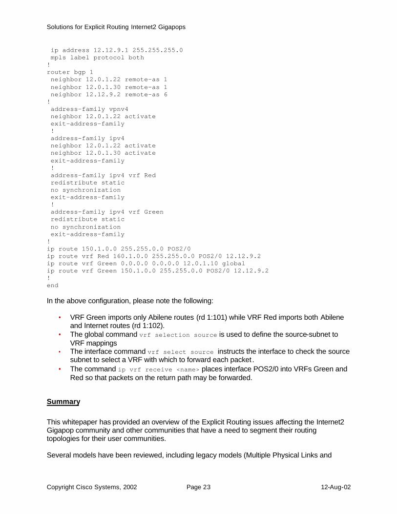
ip address 12.12.9.1 255.255.255.0 mpls label protocol both ! router bgp 1 neighbor 12.0.1.22 remote-as 1 neighbor 12.0.1.30 remote-as 1 neighbor 12.12.9.2 remote-as 6 ! address-family vpnv4 neighbor 12.0.1.22 activate exit-address-family ! address-family ipv4 neighbor 12.0.1.22 activate neighbor 12.0.1.30 activate exit-address-family ! address-family ipv4 vrf Red redistribute static no synchronization exit-address-family ! address-family ipv4 vrf Green redistribute static no synchronization exit-address-family ! ip route 150.1.0.0 255.255.0.0 POS2/0 ip route vrf Red 160.1.0.0 255.255.0.0 POS2/0 12.12.9.2 ip route vrf Green 0.0.0.0 0.0.0.0 12.0.1.10 global ip route vrf Green 150.1.0.0 255.255.0.0 POS2/0 12.12.9.2 ! end In the above configuration, please note the following:
• VRF Green imports only Abilene routes (rd 1:101) while VRF Red imports both Abilene and Internet routes (rd 1:102).
• The global command vrf selection source is used to define the source-subnet to VRF mappings
• The interface command vrf select source instructs the interface to check the source subnet to select a VRF with which to forward each packet.
• The command ip vrf receive <name> places interface POS2/0 into VRFs Green and Red so that packets on the return path may be forwarded.
Summary
This whitepaper has provided an overview of the Explicit Routing issues affecting the Internet2 Gigapop community and other communities that have a need to segment their routing topologies for their user communities. Several models have been reviewed, including legacy models (Multiple Physical Links and
Solutions for Explicit Routing Internet2 Gigapops
Copyright Cisco Systems, 2002 Page 24 12-Aug-02
Multiple ATM PVCs), deployable models (Interface-Based VRFs and Source-Selected VRFs on 7200, 7500, and 12000), and models that are under investigation (Source-Selected VRFs on 6500/7600). The purpose of this whitepaper has been to provide a primer on the relevant issues so that the reader can intelligently discuss the issues, potential solutions, and Cisco’s ability to provide solutions both now and in the future. If you have specific questions, please post them to [email protected].