Embed Size (px)
Citation preview

1
SOLUTIONS: PROBLEM SET 3
ELECTRIC CURRENT and DIRECT CURRENT CIRCUITS PART A: CONCEPTUAL QUESTIONS
A. If we connect them in series, Req = 300Ω. If we connect them in parallel, Req = 30 Ω Therefore, in order to obtain a 150 Ω resistance, we have to connect the resistors in parallel and in series… Connecting two in parallel: Req1 = 50 Ω Connecting Req1 in series with R: Req = 150 Ω.
B. c) The wire has essentially zero resistance, compared to the light bulb, and is in parallel with it. Thus, almost
all charges flow through the wire, and practically none through the bulb. C. Circuit 1: f) The potential difference across the branch of the circuit containing the switch is zero. Thus, there
is no current through it when the switch is closed, and nothing changes. Circuit 2: f) Because the light bulbs are identical, the potential difference across each is 12 V, and so nothing happens with the switch is closed.
D. Using the circuit: a) Dimmer b) Increase c) Decrease d) Increase e) Increase f) Decrease g) Nothing h) Increase i) Increase j) Decrease
E. The current will be the same because in series, the current in the branch does not change. Even if the
light bulbs are different, the current across the resistors will be the same. F. The current will be different because the light bulbs are in parallel. The current measured between
the battery will be equal to the sum of the current in each branch. The current will be greater if the resistor is smaller.
G. In parallel, the current is different but the voltage is the same. a) The reading on the voltmeter will be the same since the voltage is the same in parallel branches. b) L2 since the resistance is less and in order to have the same voltage across the branch the current
has to be greater. c) Note, c) and d) are really the same question. A light bulb which dissipates more energy will be
brighter. L2 will be brighter because it dissipates energy at the rate 2VPR
= and L2 has less
resistance than L1 (but the same V in parallel).

2
H. We have to remember the relationship between L, d and R: 2)2/(d
LALR
πρρ ==
a) If L is doubled, the resistance R will also double. As long as the diameter is the same. R∝L b) If d is doubled, the resistance R decreases by a factor of 4. R∝d-‐2. c) If L and d are doubled, the resistance R will decrease by a factor of 2.
I. Let's consider a D-cell battery. This is a device that chemically creates a charge differential; one end of the
battery is positively charged, and the other is negatively charged, so it has a voltage (typically 1.5V for alkaline cells). The conductor (air) that separates the positive and the electrons prevents the electrons from jumping straight to the positive charge and neutralizing the battery. Air is one of the best insulators around. Now if you attach a wire from one terminal to the other, you have replaced the high resistance of the air with the low resistance of the wire, and you will get a very high current as a result through the wire. It is the chemical reaction between the conductors and the electrolyte, one electrode (the cathode) becomes positively charged and the other, the anode becomes negatively charged.
J. Wrong. When a battery is new it contains stored up chemical energy which can drive charge round a circuit.
every atom has charge and the number of atoms in the battery do not change. More to the point, the actual electric current involves a flow of charge, but the battery does not run out of these charges either. There are charge carriers all over the whole circuit, in the wires, the battery, any device connected to the circuit etc and when the switch is closed to turn the current on ALL the charges throughout the whole circuit start moving at once. Over the whole period of use, the number of charges which go out of ONE end of the battery is the same as the number into the OTHER end. You can imagine it like a piece of string stretched round some pulley wheels, when you turn on (pull the string) the string everywhere starts moving at the same moment.

3
PART B: NUMERICAL QUESTIONS QUESTION 1 We obtain the resistance RA of the conductor:
2A
A rLRπ
ρ=
with rA radius of conductor A rout radius of outer conductor B rin radius of inner conductor B Therefore, the transversal area is )( 22
inout rr −π The ratio between A and B will be:
0.3)50.0(
)50.0()0.1(2
22
2
22
=−
=−
=mm
mmmmrrr
RR
A
inout
B
A
QUESTION 2 In order to find the carrier charge density needed in the current density equation, we must find the density of atoms. N: number of atoms NA: avogadro’s number (6.02 × 10²³ mol-1) m: mass M: element units
MmNN
Mm
NN A
A
=→=
The mass density of substance is m Volume Volume mρ ρ= ÷ → = ÷ . The number density of atoms, ( )An N Volume N m N Mρ ρ= ÷ = ÷ = ÷
With numerical values: 3 3 23
28 33
8.9 10 / 6.02 10 / 8.5 10 /63.5 10 /kg m atoms moln atoms m
kg mol−
× ⋅ ×= = ×
×
The current density is given from dqnAvI = q: charge n: number density of charges A: cross-sectional area vd : drift velocity
we solve for vd: 428 3 6 2
10 1.5 10 /8.5 10 / 5 10d
I Av m sqnA e atoms m m
−−
= = = ×⋅ × ⋅ ×

4
QUESTION 3
We first need to find the resistance of each resistors from RVP2
=
We have: Ω== 240601202
1R and Ω== 160901202
2R
a) when the resistors are connected in series, the current through them is the same and equal to:
AVRR
I 3.0400120
21
=Ω
=+
=ε
The voltage of each light will be:
VVVVVAIRVVAIRV
tot 1204872483.0160723.0240
21
22
11
=+=+=
=⋅Ω==
=⋅Ω==
The power dissipated in each resistor is:
WPPRIPWRIPWRIP
eqtot 0.36
4.14
6.21
2122
22
12
1
=+==
==
==
b) When the resistors are connected in parallel, the voltage across them is the same and equal to: 21120 VVVVtot ===
The equivalent resistance is found from : Ω=+= −−− 96)( 11
211 RRReq
The current in the circuit is AVR
Ieq
tot 25.196120
=Ω
==ε
The current in each light bulb is:
AIII
AVRVI
AVRVI
tot 25.1
75.0160120
5.0240120
21
22
11
=+=
=Ω
==
=Ω
==
The power dissipated in each resistor is:
5
WPPRIPWRIPWRIP
eqtottot 1509060
21
2222
1211
=+==
==
==
c) Since the rate of energy dissipated by the circuit is greater when the light bulbs are in parallel
(Pparallel > Pseries), we conclude that the brightness will also be greater in parallel. d) The light bulbs in series are more economical because the power dissipated in less. However,
there are some inconvenient to this. If one light bulb burns or is unscrewed in series, not more current flows!
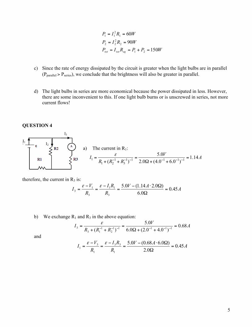
QUESTION 4 :
a) The current in R1:
1 1 1 1 1 1 11 2 3
5.0 1.14( ) 2.0 (4.0 6.0 )
VI AR R R
ε− − − − − −= = =
+ + Ω+ +
therefore, the current in R3 is:
AAVRRI
RVI 45.0
0.6)0.214.1(0.5
3
11
3
13 =
Ω
Ω⋅−=
−=
−=
εε
b) We exchange R1 and R3 in the above equation:
AVRRR
I 68.0)0.40.2(0.6
0.5)( 11111
2113
3 =++Ω
=++
=−−−−−−
ε
and
AAVRRI
RV
I 45.00.2
)0.668.0(0.5
1
33
1
31 =
Ω
Ω⋅−=
−=
−=
εε
I2
I1
I3

6
QUESTION 5 We have three unknowns (I1, I2 and I3) so three equations are needed.
a) With Kichhoff’s law of current and from the above currents in the circuit: (1) 0321 =++ III
But, the direction of one current is incorrect… It will not cause any difference because the current will be negative. Let apply the voltage law on loop 1:
(2) 00.40.100.60.2 12 =⋅Ω+⋅Ω−−−=Σ IIVVV The emf are negative since we encounter the + side first. From (2):
(3) 11
2 4.08.00.100.40.8 IAIVI +−=Ω
⋅Ω+−=
from loop 2
(4) 3 26.0 8.0 10.0 5.00 0V V I IΣ = − Ω⋅ + Ω⋅ + = we substitute I3 from equation (1): 213 III −−= in equation (4) and solve for I2:
(5) 1 2 211 8.0 ( ) 10.0 0V I I I− Ω⋅ − − + Ω⋅ =
(6) 112 444.0611.00.180.8
0.180.11 IAIVI ⋅−−=
Ω
Ω−
Ω
−=
Since equation (3) equals equation (6)
11 444.0611.04.08.0 IAIA ⋅−−=⋅+− I1 = 0.224A
Therefore we can substitute in equation (6) and (1)
AAAI 710.0224.04.08.02 −=⋅+−= in the figure, I2 has to be on the other direction AAAIII 486.0)710.0(224.0213 =−−−=−−=
I1
I2
I3
Loop1 Loop2

7
Verify the results: From the external loop:
0224.00.4486.00.8300.40.80.50.2 13
=⋅Ω+⋅Ω−
=⋅Ω+⋅Ω−+−=Σ
AAVIIVVV
b) The potential difference between points a and b is:
VVVVVVIV
ab
ab
1.10.6710.00.100.60.10 2
=−⋅Ω=−
=+⋅Ω−
QUESTION 6 a) The current when the resistors are in series will be:
mAVRRR
I 10680220100
0.10
321
=Ω+Ω+Ω
=++
=ε
The current will be the same in all resistors in series. However, the voltmeter will have a different reading, depending on the resistance.
1 1
2 23
3 3
1.09.06.8
V IR VV IR VV IR V
= =
= =
= =
b) Voltmeter 2, is connected across resistors 2 and 3.
Since 2 2 3( )V I R R= + and 321 RRR
I++
=ε
)()(
)(321
3232
3212 RRR
RRRR
RRRV
++
+=+⋅
++=
εε

8
QUESTION 7 The light bulb, the toaster and the crock are in parallel; we can find the equivalent resistance:
Ω=++=++= −−−−−−−− 15)2080240()( 11111111toastercrockbulbeq RRRR
Let consider the left hand side of the circuit has loop 1. We have a single loop:
AIIIVIRIRVV eqwire
5.7
0151120120
1
1111
=
=⋅Ω−⋅Ω−=−−=Σ
The current law: 1432 IIII =++ and because the branches are in parallel, the voltage across each resistor is the same.
VIVVVV eq 5.11215 1432 =⋅Ω====
AVI
AVI
AVI
6.5205.112
4.1805.112
46.02405.112
4
3
2
=Ω
=
=Ω
=
=Ω
=
Verify the results:
AAAAAIIII 5.76.54.146.05.74321 =++==++=
I1
I2 I3 I4
Loop1

9
QUESTION 8 a) before the switch is closed, resistors R1 and R2 are in series and R3 and R4 are also in series. The equivalent resistance for each combination is:
Ω=Ω+Ω=+=
Ω=Ω+Ω=+=
0.220.100.120.140.1000.4
4334
2112
RRRRRR
R12 and R34 are in parallel, therefore the equivalent resistance of the system is:
Ω==+ −−− 55.8)( 1112
134 eqRRR
From Ohm’s law: AVRVIRIVeq
92.255.80.25
=Ω
==→=
The current in each branch will be:
AVRV
I
AVRVI
14.10.220.25
78.10.140.25
34
3434
12
1212
=Ω
==
=Ω
==
(and I1 = I2 and I3 = I4)
Check the result: AIIItot 92.23412 =+=
b) The switch is now closed. We have to find the equivalent resistance of the circuit where R1 and R3 are in parallel and R2 and R4 are in parallel.
Ω=+=+=
Ω=+=+=−−−−−−
−−−−−−
00.5)0.100.10()(
00.3)0.1200.4()(11111
41224
111113
1113
RRRRRR
R13 and R24 are in series. The equivalent resistance of the circuit is
Ω=+=+= 00.800.500.32413 RRReq
From Ohm’s law: AVRVIRIVeq
13.300.80.25
=Ω
==→=
The current through each resistor; we have to find the voltage across each resistor, and the voltage across R1 and R3 is the same, the voltage across R2 and R4is the same.

10
AARIR
RVI
AARIR
RV
I
AARIR
RVI
AARIR
RV
I
56.10.1000.513.3
78.00.1200.313.3
56.10.1000.513.3
34.200.400.313.3
4
24
4
244
3
13
3
133
2
24
2
242
1
13
1
131
=Ω
Ω⋅===
=Ω
Ω⋅===
=Ω
Ω⋅===
=Ω
Ω⋅===
Check the result:
AAAAAAA
IIIII
12.312.313.356.156.178.034.213.3
4231
≈≈
+=+=
+=+=
c) Before the switch is closed: R1 and R2 are in series and R3 and R4 are in series. From the results in part a), we can find the voltage across each resistor.
VARIIRVVARIIRVVARIIRVVARIIRV
36.110.1014.164.130.1214.186.170.1078.114.700.478.1
434444
334333
212222
112111
=Ω⋅===
=Ω⋅===
=Ω⋅===
=Ω⋅===
Check the result:
VVVVVVVV
VVVVVtot
0.250.250.2536.1164.1386.1714.70.25
4321
==
+=+=
+=+=
The voltage at points a and b:
VVVVVVVVVVVV
b
a
4.1164.130.250.259.1714.70.250.25
3
1
=−=−=
=−=−=
The potential difference between point a and b:
VVVVVV abab 49.685.1736.11 =−=−=
11
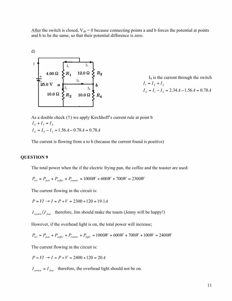
After the switch is closed, Vab = 0 because connecting points a and b forces the potential at points and b to be the same, so that their potential difference is zero. d)
IS is the current through the switch
AAAIIIIII
S
S
78.056.134.221
21
=−=−=
+=
As a double check (!!) we apply Kirchhoff’s current rule at point b
AAAIIIIII
S
S
78.078.056.134
43
=−=−=
=+
The current is flowing from a to b (because the current found is positive)
QUESTION 9
The total power when the if the electric frying pan, the coffee and the toaster are used:
WWWWPPPP toastercoffeepantot 23007006001000 =++=++= The current flowing in the circuit is:
AVPIVIP 1.191202300 =÷=÷=→=
fusesystem II 〈 therefore, Jim should make the toasts (Jenny will be happy!) However, if the overhead light is on, the total power will increase;
WWWWWPPPPP lighttoastercoffeepantot 24001007006001000 =+++=+++= The current flowing in the circuit is:
AVPIVIP 201202400 =÷=÷=→=
fusesystem II = therefore, the overhead light should not be on.
I I1 I3
IS
I2 I4

12
QUESTION 10 As one of the voltmeters indicates the voltage exceeding the battery emf, the black box contains at least one battery. Let us try the simplest combination of one battery and one resistor inside the black box. There are two different voltages across two identical ammeters. The voltage across the left ammeter (10mA) is equal to
3.6 3.3 0.3V V V− = It permits us to calculate the voltage across the right ammeter (12mA) which is equal to
120.3 0.3610
V V× =
Now it is possible to calculate the emf inside the black box:
3.6 0.36 3.96V Vε = + =
We can compare the currents in two identical voltmeters. The current of 12mA splits in the node N into two currents: 10 mA through the left ammeter and 2 mA through the left voltmeter. The internal resistance of the voltmeter is
3.6 1.80.002
VR kI
= = = Ω
Current in the right voltmeter is: 3 1.7
1800V VI mAR
= = =Ω
So, in the loop with the battery in the black box, unknown resistor and right voltmeter the following is correct:
33.96 3 5651.7 10x
V VRA−
−= = Ω
×
The direction of the inbox emf must be as it is shown in the following figure: