Embed Size (px)
Citation preview
H I G H W A Y R E S E A R C H B O A R D Bulletin 144
Some Cost Data on Prestressed Concrete Bridges
KCADEMY
National Academy of Sciences^
National Research Council p u b l i c a t i o n 4 3 ^
H I G H W A Y R E S E A R C H BOARD Officers and Members of the Executive Committee
1956
O F F I C E R S
K . B . WOODS, Chairman R E X M . W H I T T O N , Vice Chairman
F R E D BURGGRAF, Director E L M E R M . WARD, Assistant Director
Executive Commiltee
C . D . CuRTiss , ConnnisKwticr, Dineau of Public huadx
A. E . JOHNSON, Eycrnticr Sfcictaii/, Amciieaii AxHociatioji of State Highivny Officials
LOUIS JORDAN, Krpciitiur Secietaiy, Division of Eiiffnieci nig a?irf Ivtiimtnal Hesraitli, National Rencaieli Council
R. H. BALDOCK, Statr Highway Engineer, Otvrjon State Highway Coniiniiimon
PYKE JOHNSON, Connnltant, Automotive Safety Foundation
G. DONALD KENNEDY, Piemdent, Portland Cenirni Axxociatinii
O. L . K i P P , Ciinmiltant, Mini esota De]mitm< nt of Hir/iivayx
BURTON W. AIARSH, Director, Safetij and Tiaffit KiUjini: i nig Deiiaitnnnt, Ain.'iiv',,! Automobile Axmiciation
C. H. SCHOLER, Uiad, Aiijilied Mechaniis De/mi tment, Kanxcs Stt,U- College
REX M. WHITTON, Chief Engineei, Misnami Slntr Jfighway Oe/iai tweiit
K. B. WOODS, Head, School of Civil Engiveei ing and Diievtoi, Jniiil HtgJiwni; Heneaiti Piojcci, Pin due Ihiiveisity
EditoriaJ StafF
F R E D B U R G G R A F E L M E R "VI. W A R D K E R B E . ^ T ' O R I . A N :
2101 Constltuticn Avenue Washi'igton 2b, • C
The upin^una nnd conclusions exnre&bed in this publicnlion are those of the autho-t. and not necessarily those of the Hiirhway Rt-sc^irch Board.
HIGHWAY R E S E A R C H BOARD BuUetin 144
Some Cost Data on Prestreased Concrete Bridges
P R E S E N T E D A T T H E
Thirty-Fifth Annual Meeting January 17-20, 1956
1956 Washington, D. C.
Department of Design
T. E . Shelburne, Chairman Director of Research
Virginia Department of Highways
COMMITTEE ON BRIDGES
G. S. Paxson, Chairman Assistant State Highway Engineer Oregon State Highway Commission
Raymond Archibald, Division Engineer, Bureau of Public Roads, San Francisco
Russell E . Barnard, Armco Drainage and Metal Products, Inc . , Middletown, Ohio
E . L . Erickson, Chief, Bridge Branch, Bureau of Public Roads
H. deR. Gibbons, The Union Metal Manufacturing Company, Canton, Ohio
T. B. Gunter, J r . , Bridge Engineer, North Carolina State Highway and Public Works Commission
John J . Hqgan, Consulting Structural Engineer, Portland Cement Association
W. P. Kinneman, Raymond Concrete Pile Company, New York
M. N. Quade, Consulting Engineer, 51 Broadway, New York
William H. Rabe, Assistant Engineer of B r i b e s , Ohio Department of Highways
Professor C . P. Siess, Department of Civi l Engineering, University of Illinois
E . D. Smith, Director of Bridges, Kentucky Department of Highways
J . A. Williams, Bridge Engineer, Missouri State Highway Department
i i i
Contents
P R E S T R E S S E D C O N C R E T E BRIDGE COSTS
John C. Rundlett 1
COMPARATIVE COSTS OF P R E S T R E S S E D AND CONVENTIONAL CONSTRUCTION IN T R E S T L E SPANS OF FLORIDA BRIDGES
W. E . Dean 10
COST COMPARISONS O F P R E S T R E S S E D C O N C R E T E VS CONVENTIONAL-TYPE fflGHWAY BRIDGES
John J . Hogan 13
P R E S T R E S S E D C O N C R E T E IN CALIFORNIA
Arthur L . Elliott 26
Prestressed Concrete Bridge Costs JOHN C. RUNDLETT, Bridge Engineer Massachusetts Department of Public Works
• THE original intention in preparing this paper on "Prestressed Concrete Bridge Costs" was to detail fully the cost of work done in Massachusetts on this type of construction since the Department's first venture into this field in August of 1951, but the pressure of emergency flood replacement work, in addition to an accelerated highway program, has prevented a complete analysis and breakdown of these costs.
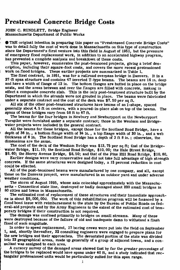
This paper, however, enumerates the post-tensioned projects, giving a brief description, including their square-foot costs, and covers the more recent pretensioned work on flood bridges. These earlier projects are summarized in Table 1.
The first contract, in 1951, was for a railroad overpass bridge in Danvers. It is a 27-ft span structure and contains 47 inverted T-type beams. The beams are 14 in. deep and have a width of flange of 12 in. The bottom flanges are butted in place on the bridge seats, and the areas between and over the flanges are filled with concrete, makmg in effect a composite concrete slab. This is the only post-tensioned structure built by the Department in which the strands were not grouted in place. The beams were fabricated under a separate contract and the cost of the deck was $7. 50 per sq ft.
All six of the other post-tensioned structures have beams of an I-shape, spaced generally about 4. 5 ft on centers, with a poured-in-place slab on top of the beams. The spans of these bridges vary from 58 ft to 67 ft.
The beams for the four bridges in Newbury and Newburyport on the Newburyport Turnpike were furnished under a separate contract; those in the Wenham and Bridge-water projects were included in the general contract.
All the beams for these bridges, except those for the Scotland Road Bridge, have a depth of 36 in., a bottom flange width of 24 in., a top flange width of 20 in., and a web thickness of 6 in. The Scotland Road Bridge has a depth of 3 ft 8 in.; otherwise, the dimensions are the same.
The cost of the deck of the Wenham Bridge was $13. 75 per sq ft; that of the Bric^e-water Bridge, $11.10; the Scotland Road Bridge, $10.00; the Hale Street Bridge, $9. 60; the Storey Avenue Bridge, $8. 50; and that of the Pine Hill Road Bridge, $10. 60.
Earlier designs were very conservative and did not take full advantage of high strength concrete. If the same structures were designed today, a 15 percent reduction in cost could be effected.
All of the post-tensioned beams were manufactured by one company, and all, except those on the Danvers project, were manufactured in an outdoor yard and under adverse weather conditions.
The storm of August 1955, whose axis coincided approximately with the Massachusetts - Connecticut state line, destroyed or badly damaged about 220 small bridges in 80 cities and towns in Massachusetts.
The estimated cost of replacement of these structures and their immediate approaches is about $9,000,000. The work of this rehabilitation program will be fmanced by a flood bond issue with reimbursement to the state by the Bureau of Public Roads on federal-aid projects and by the Army Engineers to the extent of the estimated cost of temporary bridges if their construction is not required.
The damage was confined primarily to bridges on small streams. Many of these were destroyed because of the failure of old and inadequate dams to withstand a flash flood of such magnitude.
In order to speed replacement, 17 boring crews were put into the field on September 1, and, shortly thereafter, 22 consulting engineers were engaged to prepare plans for the new bridges and their approaches. The devastated portion of the state was divided into 22 geographical areas, made up generally of a group of adjacent towns, and a consultant was assigned to each area.
A cursory survey of the damaged areas showed that by far the greater percentage of the bridges to be replaced would have spans under 40 ft, and a study indicated that rectangular pretensioned units would be particularly suited for this span range.
1
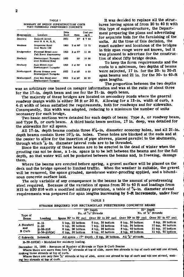
TABLE 1 SUMMARY OF BRIDGE SUPERSTRUCTURE COSTS
POST-TENSIONED PRESTRESSED CONCRETE
Municipality Location Date Built Span
Cost per sqtt
Danvers Endicott Street over B & M. R. R.
1951 27' $ 7 50
Wenham Grapevine Road over Route 128
1952 2 at 60' 13 75
Bridgewater Pleasant Street over Fall River Eiqiressway
1953 2 at 67' 11 10
Newbury Newburyport Turnpike over Scotland Road
1953 65' 10 00
Newbury Hdle Street over Newburyport Turnpike
1953 2 at 64' 9 60
Newburyport Storey Avenue over Newburyport Turnpike
1953 2 at 58' 8 50
Newburyport Pine Hill Road over Newburyport Turnpike
1953 2 at 59' 10 60
It was decided to replace all the structures having spans of from 20 to 40 ft with this type of superstructure, the Department preparing the plans and advertising for separate bids for the furnishing of the units. At the time of this decision, the exact number and locations of the bridges in this span range were not known, but it was planned to advertise for the construction of about fifty bridge decks.
To keep the form requirements and the costs to a minimum, two depths of beams were selected, 17 in. for the 20- to 30-ft span beams and 21 in. for the 30- to 40-ft span lengths.
The proportion between the two depths was an arbitrary one based on meager information and was at the ratio of about three for the 17-in. depth beam and one for the 21-in. depth beam.
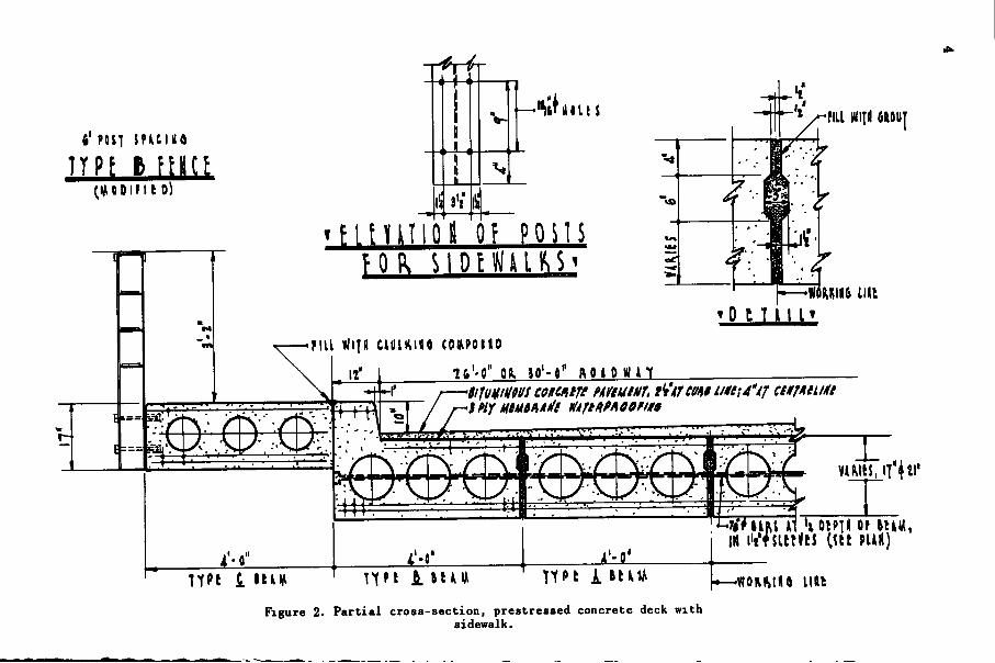
The majority of these bridges are located on secondary roads where the general roadway design width is'either 26 ft or 30 ft. Allowing for a 12-in. width of curb, a 4-ft width of beam satisfied the requirements, both for roadways and for sidewalks. Consequently, this width was adopted, reducing to a minimum the number of units necessary for each bridge.
Two basic sections were detailed for each depth of beam: Type A, or roadway beam, and Type B, or curb beam. A third basic beam section, 17 in. deep, was detailed for the sidewalks for all spans.
All 17-in. depth beams contain three 8%-m. diameter economy holes, and all 21-in. depth beams contain three lOVa-in. holes. These holes are blocked at the ends and at the center to allow for the insertion of pipe sleeves, placed parallel to the abutments, through which ''/4-in. diameter lateral rods are to be threaded.
Since the majority of these beams are to be erected in the dead of winter when the grouting can not be done, a 1-in. space is to be left between the beams and for the full depth, so that water will not be pocketed between the beams and, in freezing, damage them.
Where the beams are erected before spring, a gravel surface will be placed on the deck and the bridge opened to limited traffic. When the weather is suitable, the gravel will be removed, the space grouted, membrane water-proofing applied, and a bituminous concrete surface laid.
The only variable of any consequence in the beams is the amount of prestressing steel required. Because of the variation of spans from 20 to 40 ft and loadings from H15 to H20 S16 with a modified military provision, a table of %-in. diameter strand requirements was prepared for span lengths increasing by 5-f t Increments, under four
T A B L E 2
STRANDS REQUIRED FOR RECTANGULAR PRESTRESSED CONCRETE BEAMS 17" Depth 21" Depth
No. ot 7," Strands No. of '^" Strands Spans 20' to 25' mcl Over 25' to 30' incl Over 30' to 35' mcl Over
R tnn 29. Vmtfnm R tnn. 28 hnttnm 6 ton. 30 bottom 8 t
Type of Beam Loading 35' to 40' incl
A Standard and
B Curb
H-15 H-20 H-20-S16 H-20-S16(M)
5 top, 22 bottom 5 top, 26 bottom 6 top, 26 bottom 6 top, 30 bottom
6 top, 28 bottom 7 top, 32 bottom 8 top, 36 bottom Stop, 40 bottom
6 top, 30 bottom 8 top, 34 bottom 8 top, 40 bottom Stop, 40 bottom
Stop, 36 bottom 10 top, 44 bottom 11 top, 50 bottom 11 top, 50 bottom
C Sidewalk Sidewalk Al l spans - 17" Depth - 6 top, 26 bottom. All '^" strands.
H-20-S16(M) = Modified for military loading. December 15, 1955 - Revision of Number of Strands m Type B Curb Beams
Where there are more than five %" strands at top of slab, move two strands to top of curb and add one strand, making three strands at top of curb.
Where there are only five %" strands at top oi slab, move one strand to top of curb and add one strand, mak-ing two strands at top of curb.
iHiimi Mii mil b< POtT SPUUS
TYPE c m u (.M 0 01 n 10^
M » unit t< POtT SMCItt
TYPt A fHCt (« 0 0 I M t 0
mo MM
jj-'t^^^flLL Win flftOIII
KOI KIMO LIU
2 6'-0" Oft 30-O' ftO» OWAT
•SlTUMIHIilS tOHCniTI Hf/tUtllT, ti'tTCUAB t/Uf l 4'Af CtUTnilllli
TYPl 1 S U t t
I . ^ ^ ^ ^
%V8*ftS »T h OIPH Of (CtM IH AWWiW
^ \ \ \ PUIIl
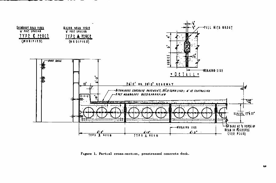
Figure 1. Partial cross-section, prestressed concrete deck.
6' POSl S P U I I I 6
T
n t H T i o i i 0? p o n s
r i l l wi j i i c t t fU i tQ (OAPomo
I I ' 1 T t ' - f l " OIL » ' - 0 " ftOIOWU
^ ^ ^ ^ ^
n ' t i j « u
ot»Tii or t t u , IN i"t '^j i i t«e$ C^it puH)
-WOKIMIIO l U t
Figure 2. Partial cross-section, prestressed concrete deck with sidewalk.
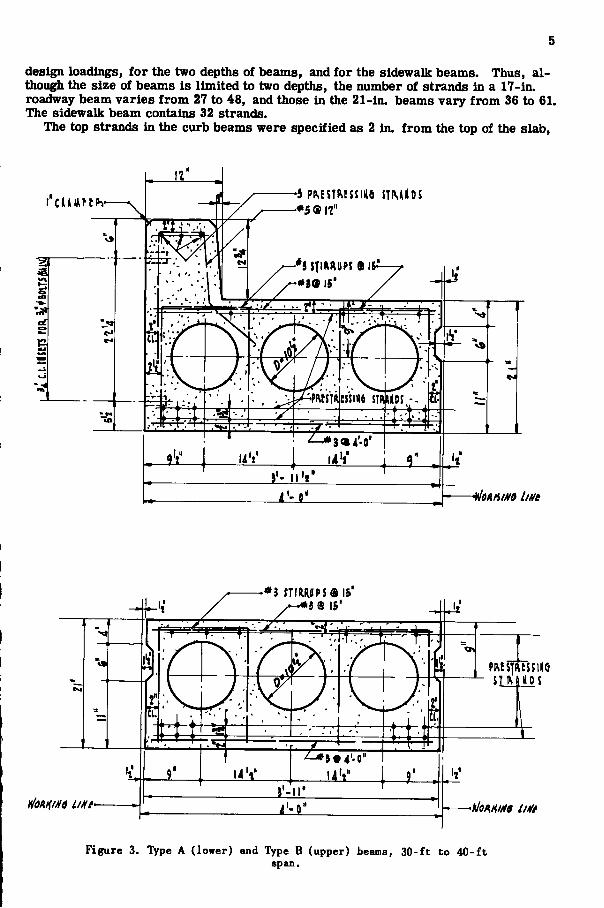
design loadings, for the two depths of beams, and for the sidewalk beams. Thus, although the size of beams is limited to two depths, the number of strands in a 17-in. roadway beam varies from 27 to 48, and those in the 21-in. beams vary from 36 to 61. The sidewalk beam contains 32 strands.
The top strands in the curb beams were specified as 2 in. from the top of the slab,
•5 p^EST^^5Slllfl STMIIOJ
*i9 16'
'*l fTIRRIIPS® IS"
mSpSJl l lQ
n i l "
Homm line
Figure 3. Type A (lower) and Type B (upper) beams, 30-ft to 40-ft span.
6
but tension in the top of the monolithically poured curb section requires the moving of some strands to the top of the curb and the addition of another strand.
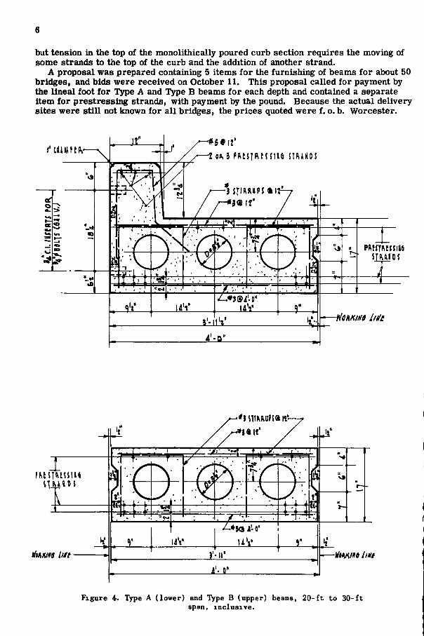
A proposal was prepared containing 5 items for the furnishing of beams for about 50 bridges, and bids were received on October 11. This proposal called for payment by the lineal foot for Type A and Type B beams for each depth and contained a separate item for prestressing strands, with payment by the pound. Because the actual delivery sites were still not known for all bridges, the prices quoted were f. o. b. Worcester.
l " t l H t t f t | i , -
er
oc —•
Us*
# 5 • 1 2 '
3 s f i R K i i P S ftir
i iV
PMflRcsjiiie SIMIOJ
-flcumo liilt
' j s m u f s a f t ' -
Figure 4. Type A (lower) and Type B (upper) beams, 20-ft to 30-ft span, inclusive.
5 S P K M <a a ' , i'-r
>4 C.I. lis UTS m s ; o o i T 5 W u v . ) - 1
I' C U K f l h * } « I f
p^^!l^^ssl^6 s u u o s ( V J
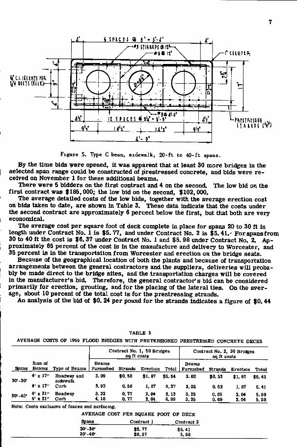
Figure 5. Type C beam, sidewalk, 20-ft to 40-ft spans.
By the time bids Y ere opened, it was apparent that at least 30 more bridges in the selected span range could be constructed of prestressed concrete, and bids were received on November 1 for these additional beams.
There were 5 bidders on the first contract and 4 on the second. The low bid on the first contract was $185,000; the low bid on the second, $102,000.
The average detailed costs of the low bids, together with the average erection cost on bids taken to date, are shown in Table 3. These data indicate that the costs under the second contract are approximately 6 percent below the first, but that both are very economical.
The average cost per square foot of deck complete in place for spans 20 to 30 ft in length under Contract No. 1 is $5. 77, and under Contract No. 2 is $5.41.' Forspansfrom 30 to 40 ft the cost is $6. 37 under Contract No. 1 and $5. 98 under Contract No. 2. Approximately 65 percent of the cost is in the manufacture and delivery to Worcester, and 35 percent is in the transportation from Worcester and erection on the bridge seats.
Because of the geographical location of both the plants and because of transportation arrangements between the general contractors and the suppliers, deliveries will probably be made direct to the bridge sites, and the transportation charges will be covered in the manufacturer's bid. Therefore, the general contractor's bid can be considered primarily for erection, grouting, and for the placing of the lateral ties. On the average, about 10 percent of the total cost is for the prestressing strands.
An analysis of the bid of $0. 24 per pound for the strands indicates a figure of $0.44
T A B L E 3
AVERAGE COSTS OF 1955 FLOOD BRIDGES WITH PRETENSIQNED PRESTRESSED CONCRETE DECKS
Spans Size of Beams Type of Beams
Contract No. 1, 50 Bridges sq ft costs
Contract No. 2, 30 Bridges sq ft costs
Spans Size of Beams Type of Beams
Beams Furnished Strands Erection Total
Beams Furnished Strands Erection Total
4' X 17" Roadway and 3.09 $0.58 $1. 87 $5.54 3. 02 $0.52 $1.87 $5.41 20'-30' sidewalk
$0.52 $1.87 $5.41
4' X 17" Curb 3. 92 0.S8 1. 87 6. 37 3. 02 0.52 1. 87 5. 41
30'-40" 4' X 21" Roadway 3. 32 0.77 2.04 6.13 3. 25 0.69 2. 04 5. 98 30'-40" 4' X 21" Curb 4.18 0. 77 2.04 6.99 3.25 0.69 2. 04 5. 98
Note: Costs exclusive of fences and surfacing. AVERAGE COST P E R SQUARE FOOT OF DECK Spans Contract 1 Contract 2
20'-30" 30'-40'
$5. 77 $6.37
$5.41 5.98

F i l l I'l^ u»n «in» <i\m n ntcomo, HID vnii wm i] nnmi m
Fimsii mn uMs pu tu tuo mm
\mmt
( i F M M j J ^ t P )
6US pucto III I'l^ nnhi. im |o t t , i i i K u t t o , ton tiios, tto Finto win m\ int mim.
7
• Ubl FOI>> 17 6 1 U i m t FOK 71' 5 t U
Figure 6. Plan of prestressed concrete deck.
9
per sq ft for a 17-in. depth beam for an HIS loading and for a 20-ft span, and a cost of $0. 78 per sq ft for the same depth beam on a 30-ft span and an H20 S16 loading. For similar loadings and for the minimum and maximum spans of the 21-in. depth beam, the cost varies from $0. 59 to $1. 00 per sq ft.
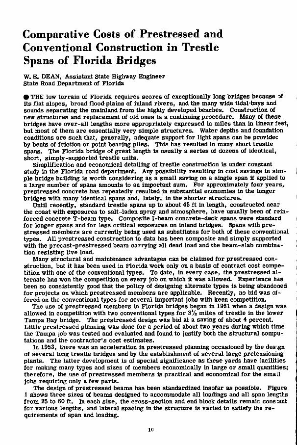
Comparative Costs of Prestressed and Conventional Construction in Trestle Spans of Florida Bridges W. E . DEAN, Assistant State Highway Engineer State Road Department of Florida
• THE low terrain of Florida requires scores of exceptionally long bridges because of its flat slopes, broad flood plains of inland rivers, and the many wide tidal-bays and sounds separating the mainland from the highly developed beaches. Construction of new structures and replacement of old ones is a continuing procedure. Many of these bridges have over-all lengths more appropriately expressed in miles than in linear feet, but most of them are essentially very simple structures. Water depths and foundation conditions are such that, generally, adequate support for light spans can be providec by bents of friction or point bearing piles. This has resulted in many short trestle spans. The Florida bridge of great length is usually a series of dozens of identical, short, simply-supported trestle units.
Simplification and economical detailing of trestle construction is under constant study in the Florida road department. Any possibility resulting In cost savings in simple bridge building is worth considering as a small saving on a single span if applied to a large number of spans amounts to an important sum. For approximately four years, prestressed concrete has repeatedly resulted in substantial economies In the longer bridges with many identical spans and, lately, in the shorter structures.
Until recently, standard trestle spans up to about 45 ft in length, constructed near the coast with eTaposnres to salt-laden spray and atmosphere, have usually been of reinforced concrete T-beam type. Composite I-beam concrete-deck spans were standard for longer spans and for less critical exposures on inland bridges. Spans with prestressed members are currently being used as substitutes for both of these conventional types. All prestressed construction to data has been composite and simply supported with the precast-prestressed beam carrying all dead load and the beam-slab combination resisting live load.
Many structural and maintenance advantages can be claimed for prestressed construction, but it has been used in Florida work only on a basis of contract cost competition with one of the conventional types. To date, in every case, the prestressed alternate has won the competition on every job on which it was allowed. Experience has been so consistently good that the policy of designing alternate types is being abandoned for projects on which prestressed members are applicable. Recently, no bid was offered on the conventional types for several important jobs with keen competition.
The use of prestressed members in Florida bridges began in 1951 when a design was allowed in competition with two conventional types for 3% miles of trestle in the lower Tampa Bay bridge. The prestressed design was bid at a saving of about 4 percent. Little prestressed planning was done for a period of about two years during which time the Tampa job was tested and evaluated and found to justify both the structural computations and the contractor's cost estimates.
In 1953, there was an acceleration in prestressed planning occasioned by the design of several long trestle bridges and by the establishment of several large pretensioning plants. The latter development is of special significance as these yards have facilities for making many types and sizes of members economically in large or small quantities; therefore, the use of prestressed members is practical and economical for the small jobs requiring only a few parts.
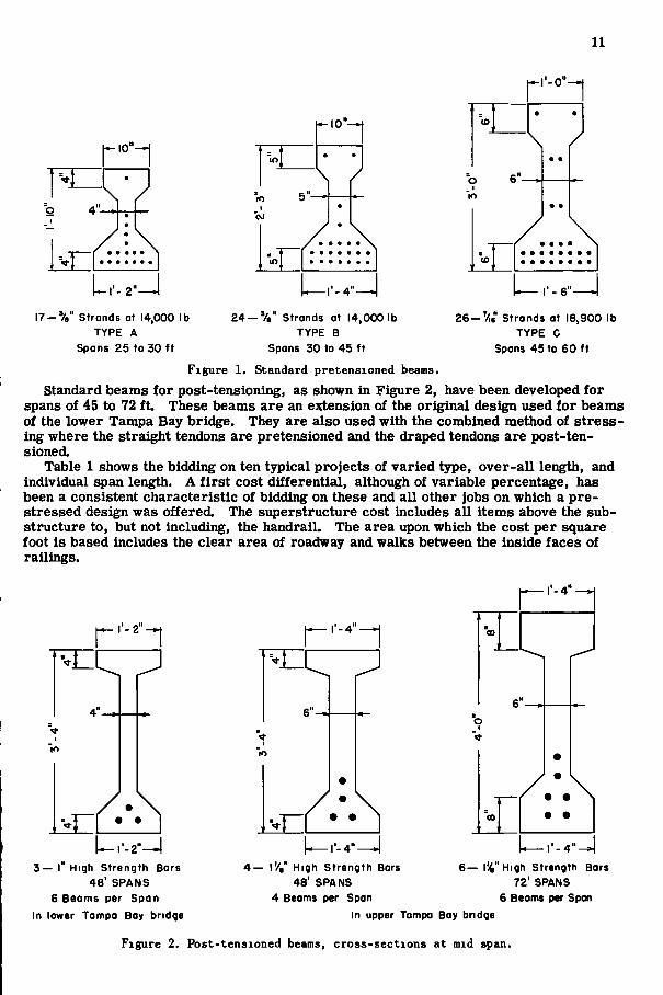
The design of prestressed beams has been standardized insofar as possible. Figure 1 shows three sizes of beams designed to accommodate all loadings and all span lengths from 25 to 60 ft. In each size, the cross-section and end block details remain cons:ant for various lengths, and lateral spacing in the structure is varied to satisfy the requirements of span and loading.
10
11
h-i-o"-*f
» - 1 0 " ^
\ /
- 1 0 " ^
"lO • •
\ / o 1
lO
I 7 - ' / B " Strands at 14,000 lb TYPE A
Spans 2 5 to 3 0 ft
2 4 - V , " Strands at 14,000 lb TYPE B
Spans 3 0 to 4 5 ft
- I - 6 —
2 6 - V Strands at 18,900 lb TYPE C
Spans 4 5 to 6 0 ft
Figure 1. Standard pretensioned beams. Standard beams for post-tensioning, as shown in Figure 2, have been developed for
spans of 45 to 72 ft. These beams are an extension of the original design used for beams of the lower Tampa Bay bridge. They are also used with the combined method of stressing where the straight tendons are pretensioned and the draped tendons are post-ten-sioned.
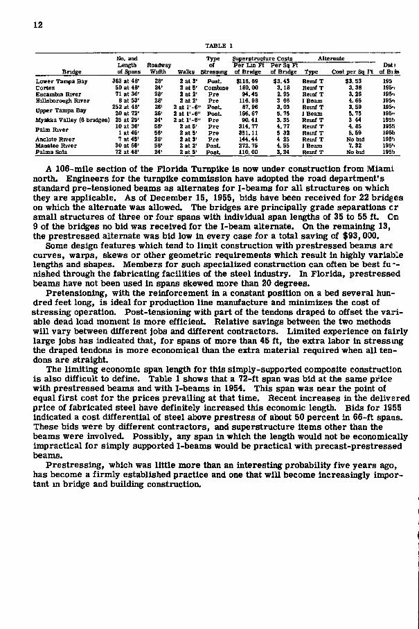
Table 1 shows the bidding on ten tjrpical projects of varied type, over-all length, and individual span length. A first cost differential, although of variable percentage, has been a consistent characteristic of bidding on these and all other jobs on which a pre-stressed design was offered. The superstructure cost includes all items above the substructure to, but not including, the handrail. The area upon which the cost per square foot is based includes the clear area of roadway and walks between the inside faces of railings.
— I ' - 2 " —
I
"ro "lO
9 •
• l ' -4"-
o I
V
^ r - 2 " - ^
3 — I High Strength Bars 4 8 ' SPANS
6 Beams per Span In lower Tampa Boy bridge
^ | - - 4 " - J 4 — i V High Strength Bars
48' SPANS 4 Beams per Span
r - 4 "
6— I'V'High Strength Bars 72' SPANS
6 Beams per Span In upper Tampa Bay bridge
Figure 2. Post-tensioned beams, cross-sections at mid span.
12
TABLE 1
No, and Type Superstructure Costs Alternate Length Roadway of Per Lin Ft Per Sq Ft Dat;
Bridge of Spans Width Walks Stressing of Bridge of Bridge Type Cost per Sq I t of Bils Lower Tampa Bay 363 at 48' 28' 2 at 3' Post. $116.69 $3.43 Remf T $3. 53 195 Cortez 50 at 48' 24' 2 at 5' Combme 180.00 3.18 Reinf T 3. 38 195'> Escambia River 71 at 36' 28' 2 at 2< Pre 94.45 2.95 Heinf T 3.26 195'> Hillsborough River 8 at 53' 28' 2 at 2' Pre 116. 98 3 66 I Beam 4. 66 195'>
252 at 48' 26' 2 at l'-6' ' Post. 87.96 3.03 Reinf T 3.59 195*1 upper Tampa Bay 20 at 72' 26' 2 at l'-6' ' Post. 166.67 5. 75 I Beam 5.75 195" Myakka Valley (6 bridges) 25 at 25' 24' 2 at l'-6' 1 Pre 90.41 3. 35 Remf T 3 44 195!i
10 at 36' 56' 2 at 5' Pre 314. 77 4. 77 Reinf T 4.85 1955 Palm River 1 at 45' 56' 2 at 5' Pre 351.11 5 32 Reinf T 5. 59 195[i Anclote River 7 at 45' 28' 2 at 3' Pre 144.44 4 25 Reinf T No bid 195') Manatee River 30 at 66' 56' 2 at 2' Post. 272. 75 4. 55 I Beam 7.32 195'i Palma Sola 72 at 48' 24' 2 at 5' Post 110. 00 3.24 Reinf T No bid 195b
A 106-inlle section of the Florida Turnpike is now under construction from Miami north. Engineers for the turnpike commission have adopted the road department's standard pre-tensioned beams as alternates for I-beams for all structures on which they are applicable. As of December 15, 1955, bids have been received for 22 bridges on which the alternate was allowed. The bridges are principally grade separations cr small structures of three or four spans with individual span lengths of 35 to 55 ft. On 9 of the bridges no bid was received for the I-beam alternate. On the remaining 13, the prestressed alternate was bid low in every case for a total saving of $93,000.
Some design features which tend to limit construction with prestressed beams are curves, warps, skews or other geometric requirements which result in highly variable lengths and shapes. Members for such specialized construction can often be best fu ' -nished through the fabricating facilities of the steel industry. In Florida, prestressed beams have not been used in spans skewed more than 20 degrees.
Pretensioning, with the reinforcement in a constant position on a bed several hundred feet long, is ideal for production line manufacture and minimizes the cost of stressing operation. Post-tensioning with part of the tendons draped to offset the var i able dead load moment is more efficient. Relative savings between the two methods will vary between different jobs and different contractors. Limited experience on fairly large jobs has indicated that, for spans of more than 45 ft, the extra labor in stress ing the draped tendons is more economical than the extra material required when all tendons are straight.
The limiting economic span length for this simply-supported composite construction is also difficult to define. Table 1 shows that a 72-ft span was bid at the same price with prestressed beams and with I-beams in 1954. This span was near the point of equal f irst cost for the prices prevailing at that time. Recent increases in the delivered price of fabricated steel have definitely increased this economic length. Bids for 1955 indicated a cost differential of steel above prestress of about 50 percent in 66-ft spaas. These bids were by different contractors, and superstructure items other than the beams were involved. Possibly, any span in which the length would not be economically impractical for simply supported I-beams would be practical with precast-prestressed beams.
Prestressing, which was little more than an interesting probability five years ago, has become a firmly established practice and one that will become increasingly important m bridge and building construction.
Cost Comparisons of Prestressed Concrete vs Conventional-Type Highway Bridges JOHN J . HOGAN, Consulting Structural Engineer Portland Cement Association
• INCREASING use of prestressed concrete for bridges poses new problems to the bridge engineer. Each project must be studied as a separate entity unless the case involves a number of similar bridges.
Since the construction of the Walnut Lane Bridge m Philadelphia's Fairmont Park in 1948, the number of prestressed bridges constructed has been numerous. However, up to the present, little data on the reasons for their selection and the relative costs have been tabulated. Mere figures on the cost per square foot of deck area do not tell much unless some pertinent facts are known about the geological location, site conditions, number of beams used, fabrication, plant locations, transportation distances, and availability of contractors willing to bid prestressed concrete projects, since all of these factors play a part in the analyses of cost data.
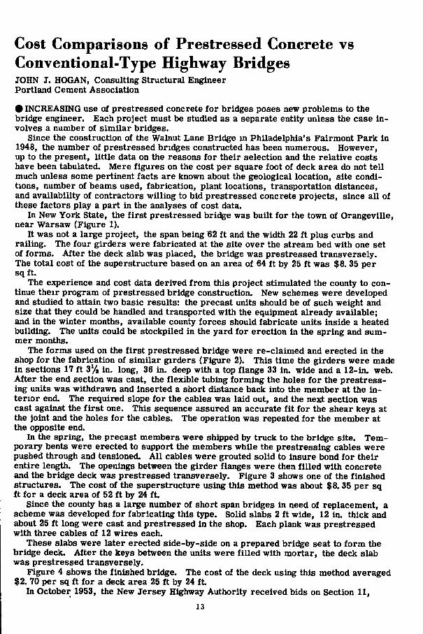
In New York State, the first prestressed bridge was built for the town of Orangeville, near Warsaw (Figure 1).
It was not a large project, the span being 62 ft and the width 22 ft plus curbs and railing. The four girders were fabricated at the site over the stream bed with one set of forms. After the deck slab was placed, the bridge was prestressed transversely. The total cost of the superstructure based on an area of 64 ft by 25 ft was $8. 35 per sq ft.
The experience and cost data derived from this project stimulated the county to continue their program of prestressed bridge construction. New schemes were developed and studied to attain two basic results: the precast units should be of such weight and size that they could be handled and transported with the equipment already available; and in the winter months, available county forces should fabricate units inside a heated building. The units could be stockpiled in the yard for erection in the spring and summer months.
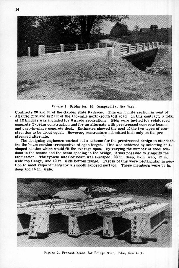
The forms used on the first prestressed bridge were re-claimed and erected in the shop for the fabrication of similar girders (Figure 2). This time the girders were made in sections 17 ft in. long, 36 in. deep with a top flange 33 in. wide and a 12-in. web. After the end section was cast, the flexible tubing forming the holes for the prestress-ing units was withdrawn and inserted a short distance back into the member at the interior end. The required slope for the cables was laid out, and the next section was cast against the f irst one. This sequence assured an accurate fit for the shear keys at the joint and the holes for the cables. The operation was repeated for the member at the opposite end.
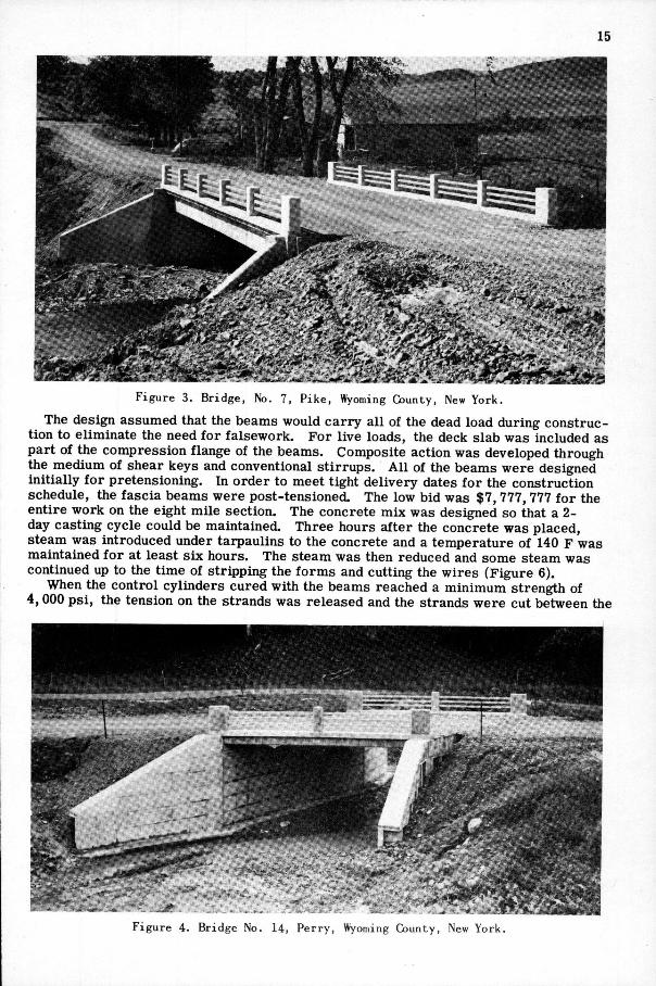
In the spring, the precast members were shipped by truck to the bridge site. Temporary bents were erected to support the members while the prestressing cables were pushed through and tensioned. Al l cables were grouted solid to insure bond for their entire length. The openings between the girder flanges were then filled with concrete and the bridge deck was prestressed transversely. Figure 3 shows one of the finished structures. The cost of the superstructure using this method was about $8. 35 per sq ft for a deck area of 52 ft by 24 ft.
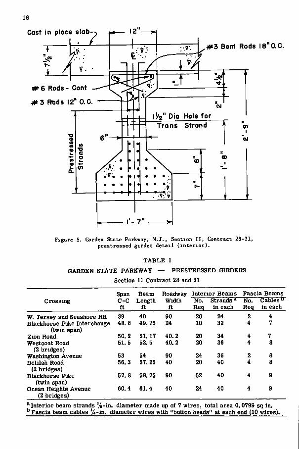
Since the county has a large number of short span bridges in need of replacement, a scheme was developed for fabricating this type. Solid slabs 2 ft wide, 12 in. thick and about 25 ft long were cast and prestressed in the shop. Each plank was prestressed with three cables of 12 wires each.
These slabs were later erected side-by-side on a prepared bridge seat to form the bridge deck. After the keys between the units were filled with mortar, the deck slab was prestressed transversely.
Figure 4 shows the finished bridge. The cost of the deck using this method averaged $2. 70 per sq ft for a deck area 25 ft by 24 f t
In October 1953, the New Jersey Highway Authority received bids on Section 11,
13
14
F i g u r e 1. Br idge No. 10, O r a n g e v i l l e , New York .
Contracts 28 and 31 of the Garden State Parkway. This eight nn ile section is west of Atlantic City and is part of the 165-mile north-south toll road. In this contract, a total of 12 bridges was included for 8 grade separations. Bids were invited for reinforced concrete T-beam construction and for an alternate with prestressed concrete beams and cast-in-place concrete deck. Estimates showed the cost of the two types of construction to be about equal. However, contractors submitted bids only on the prestressed alternate.
The designing engineers worked out a scheme for the prestressed design to standardize the beam section irrespective of span length. This was achieved by selecting an 1-shaped section which would fit the average span. By varying the number of steel tendons in the beams and the beam spacing in the bridge, it was possible to simplify the fabrication. The typical interior beam was I-shaped, 33 in. deep, 6-in. web, 12 in. wide top flange, and 19 in. wide bottom flange. Fascia beams were rectangular in section to meet requirements for a smooth exposed surface. These members were 33 in. deep and 16 in. wide.
F i g u r e 2. P r e c a s t beams for Bridge No.7, P i k e , New York .
15
F i g u r e 3. B r i d g e , No. 7, P i k e , Wyoming County, New Y o r k .
The design assumed that the beams would carry all of the dead load during construction to eliminate the need for falsework. For live loads, the deck slab was included as part of the compression flange of the beams. Composite action was developed through the medium of shear keys and conventional stirrups. Al l of the beams were designed initially for pretensioning. In order to meet tight delivery dates for the construction schedule, the fascia beams were post-tensioned. The low bid was $7, 777, 777 for the entire work on the eight mile section. The concrete mix was designed so that a 2-day casting cycle could be maintained. Three hours after the concrete was placed, steam was introduced under tarpaulins to the concrete and a temperature of 140 F was maintained for at least six hours. The steam was then reduced and some steam was continued up to the time of stripping the forms and cutting the wires (Figure 6).
When the control cylinders cured with the beams reached a minimum strength of 4,000 psi, the tension on the strands was released and the strands were cut between the
•aiiMiitllillMlr|iiii|iii[iillll 111 imi,;«.
F i g u r e 4. Bridge No. 14, P e r r y , Wyoming County, New York.
16
Cast in place s lab
^3 Bent Rods I 8 " 0 . C .
# • 6 Rods - Cont
• # 3 Rods 12" O.C.
11 2" Dia Hole for T r a n s Strand
F i g u r e 5. Garden S t a t e Parkway, N . J . , S e c t i o n I I , Contract 28-31, p r e s t r e s s e d g i r d e r d e t a i l ( i n t e r i o r ) .
T A B L E 1
GARDEN STATE PARKWAY — PRESTRESSED GIRDERS Section 11 Contract 28 and 31
Span Beam Roadway Interior Beams Fascia Beams Crossing C - C Length Width No. Strands No. Cables "
ft ft ft Req in each Req in each W. Jersey and Seashore RR 39 40 90 20 24 2 4 Blackhorse Pike Interchange 48. 8 49. 75 24 10 32 4 7
(twm span) Zion Road 50. 2 51. 17 40. 2 20 34 4 7 Westcoat Road 51.5 52.5 40.2 20 36 4 8
(2 bridges) Washington Avenue 53 54 90 24 36 2 8 Delilah Road 56.3 57. 25 40 20 40 4 8
(2 bridges) Blackhorse Pike 57.8 58. 75 90 52 40 4 9
(twin span) Ocean Heights Avenue 60.4 61.4 40 24 40 4 9
(2 bridges) ^Interior beam strands %-in. diameter made up of 7 wires, total area 0. 0799 sq in. ^ Fascia beam cables %-in. diameter wires with "button heads" at each end (10 wires).
17
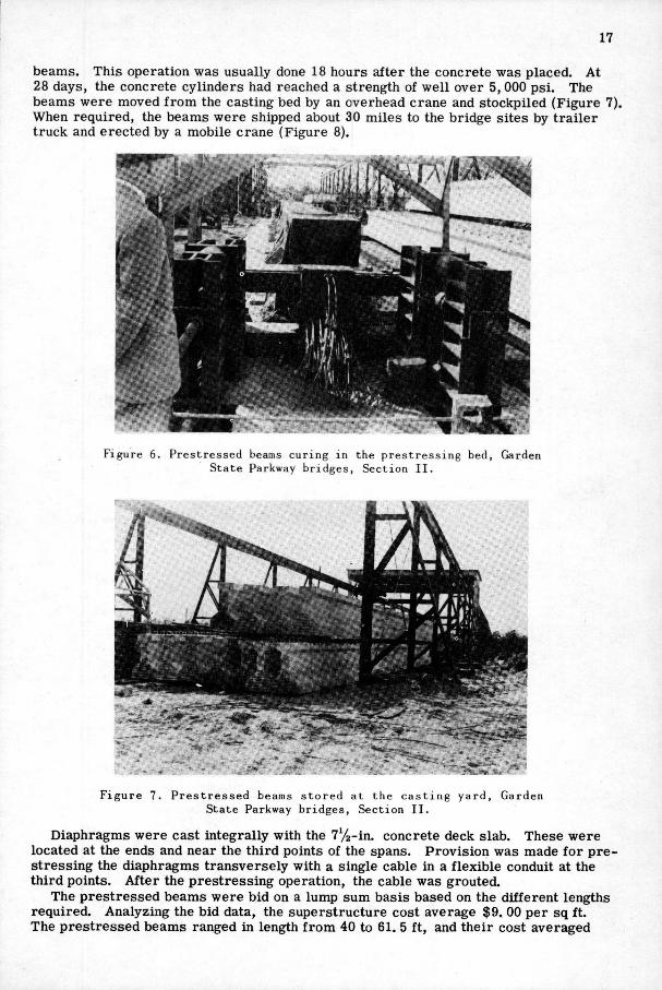
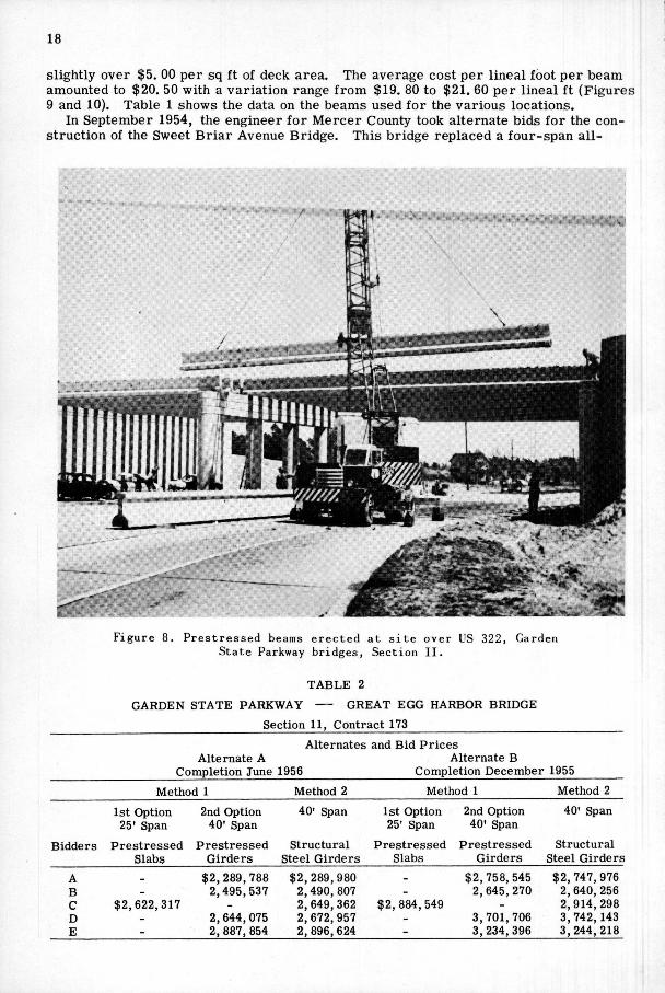
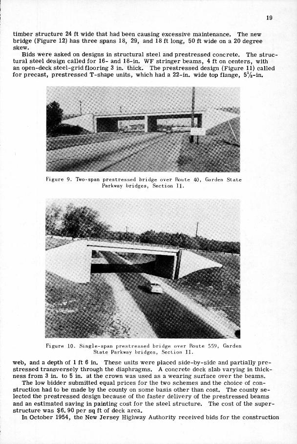
beams. This operation was usually done 18 hours after the concrete was placed. At 28 days, the concrete cylinders had reached a strength of well over 5, 000 psi. The beams were moved from the casting bed by an overhead crane and stockpiled (Figure 7), When required, the beams were shipped about 30 miles to the bridge sites by trailer truck and erected by a mobile crane (Figure 8).
F i g u r e 6. P r e s t r e s s e d beams c u r i n g i n the p r e s t r e s s i n g bed, Garden S t a t e Parkway b r i d g e s , S e c t i o n I I .
F i g u r e 7. P r e s t r e s s e d beams s t o r e d a t the c a s t i n g y a r d . S t a t e Parkway b r i d g e s , S e c t i o n I I .
Garden
Diaphragms were cast integrally with the 7y2-in. concrete deck slab. These were located at the ends and near the third points of the spans. Provision was made for prestressing the diaphragms transversely with a single cable in a flexible conduit at the third points. After the prestressing operation, the cable was grouted.
The prestressed beams were bid on a lump sum basis based on the different lengths required. Analyzing the bid data, the superstructure cost average $9. 00 per sq ft. The prestressed beams ranged in length from 40 to 61. 5 ft, and their cost averaged
slightly over $5. 00 per sq ft of deck area. The average cost per lineal foot per beam amounted to $20. 50 with a variation range from $19. 80 to $21. 60 per lineal ft (Figures 9 and 10). Table 1 shows the data on the beams used for the various locations.
In September 1954, the engineer for Mercer County took alternate bids for the construction of the Sweet Briar Avenue Bridge. This bridge replaced a four-span al l -
F i g u r e 8. P r e s t r e s s e d beams e r e c t e d a t s i t e over US 322, S t a t e Parkway b r i d g e s , S e c t i o n I I .
Garde
T A B L E 2
GARDEN STATE PARKWAY GREAT E G G HARBOR BRIDGE
Section 11, Contract 173
Alternates and Bid Prices Alternate A Alternate B
Completion June 1956 Completion December 1955
Method 1 Method 2 Method 1 Method 2
1st Option 25' Span
2nd Option 40' Span
40' Span 1st Option 25' Span
2nd Option 40' Span
40' Span
Bidders Prestressed Slabs
Prestressed Girders
Structural Steel Girders
Prestressed Slabs
Prestressed Girders
Structural Steel Girders
A B C D E
$2,622,317
$2,289,788 2,495,537
2,644,075 2, 887, 854
$2,289,980 2,490, 807 2,649,362 2,672,957 2,896,624
$2, 884,549
$2,758, 545 2,645,270
3, 701, 706 3,234,396
$2,747,976 2,640, 256 2,914, 298 3, 742, 143 3,244,218
19
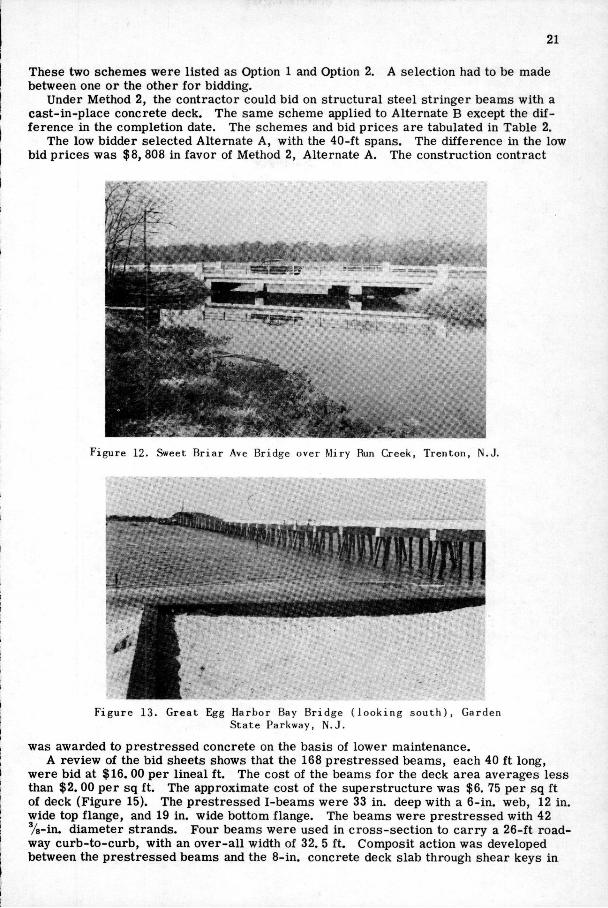
timber structure 24 ft wide that had been causing excessive maintenance. The new bridge (Figure 12) has three spans 18, 29, and 18 ft long, 50 ft wide on a 20 degree skew.
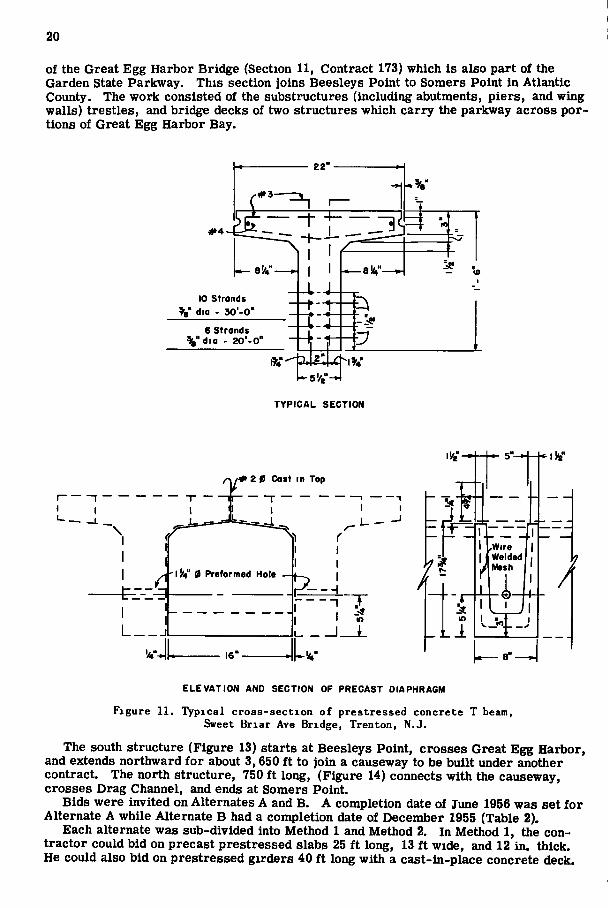
Bids were asked on designs in structural steel and prestressed concrete. The structural steel design called for 16- and 18-in. WF stringer beams, 4 ft on centers, with an open-deck steel-grid flooring 3 in. thick. The prestressed design (Figure 11) called for precast, prestressed T-shape units, which had a 22-in. wide top flange, 5%-m.
F i g u r e 9. Two-span p r e s t r e s s e d br idge over Route 40, Garden S t a t e Parkway b r i d g e s , S e c t i o n I I .
F i g u r e 10. S i n g l e - s p a n p r e s t r e s s e d br idge over Route 559, S t a t e Parkway b r i d g e s , S e c t i o n 11.
Garden
web, and a depth of 1 ft 6 in. These units were placed side-by-side and partially prestressed transversely through the diaphragms. A concrete deck slab varying in thickness from 3 in. to 5 in. at the crown was used as a wearing surface over the beams.
The low bidder submitted equal prices for the two schemes and the choice of construction had to be made by the county on some basis other than cost. The county selected the prestressed design because of the faster delivery of the prestressed beams and an estimated saving in painting cost for the steel structure. The cost of the superstructure was $6. 90 per sq ft of deck area.
In October 1954, the New Jersey Highway Authority received bids for the construction
20
of the Great Egg Harbor Bridge (Section 11, Contract 173) which is also part of the Garden State Parkway. This section joins Beesleys Point to Somers Point in Atlantic County. The work consisted of the substructures (including abutments, piers, and wing walls) trestles, and bridge decks of two structures which carry the parkway across portions of Great Egg Harbor Bay.
2 2 "
*4
x # 3 - ^
10 s t rands V dio - 3 0 ' - 0 '
6 St rands %"dia - 2 0 ' - 0 '
T Y P I C A L S E C T I O N
I L. .
2 0 Cast in Top
Ikt" 0 Preformed Hole
E L E V A T I O N AND S E C T I O N OF P R E C A S T DIAPHRAGM
F i g u r e 11. T y p i c a l c r o s s - s e c t i o n of p r e s t r e s s e d c o n c r e t e T beam, Sweet B r i a r Ave Bridge, Trenton, N.J.
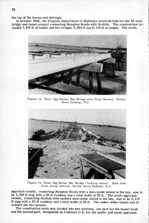
The south structure (Figure 13) starts at Beesleys Point, crosses Great Egg Harbor, and extends northward for about 3,650 ft to join a causeway to be built under another contract. The north structure, 750 ft long, (Figure 14) connects with the causeway, crosses Drag Channel, and ends at Somers Point.
Bids were invited on Alternates A and B. A completion date of June 1956 was set for Alternate A while Alternate B had a completion date of December 1955 (Table 2).
Each alternate was sub-divided into Method 1 and Method 2. In Method 1, the contractor could bid on precast prestressed slabs 25 ft long, 13 ft wide, and 12 in. thick. He could also bid on prestressed girders 40 ft long with a cast-in-place concrete deck.
21
These two schemes were listed as Option 1 and Option 2. A selection had to be made between one or the other for bidding.
Under Method 2, the contractor could bid on structural steel stringer beams with a cast-in-place concrete deck. The same scheme applied to Alternate B except the difference in the completion date. The schemes and bid prices are tabulated in Table 2.
The low bidder selected Alternate A, with the 40-ft spans. The difference in the low bid prices was $8, 808 in favor of Method 2, Alternate A. The construction contract
umt*....
F i g u r e 12. Sweet B r i a r Ave Bridge over Miry Run Creek, Trenton , N . J .
F i g u r e 13. G r e a t Egg Harbor Bay B r i d g e ( l o o k i n g s o u t h ) , Garden S t a t e Parkway, N . J .
was awarded to prestressed concrete on the basis of lower maintenance. A review of the bid sheets shows that the 168 prestressed beams, each 40 ft long,
were bid at $16. 00 per lineal ft. The cost of the beams for the deck area averages less than $2. 00 per sq ft. The approximate cost of the superstructure was $6. 75 per sq ft of deck (Figure 15). The prestressed I-beams were 33 in. deep with a 6-in. web, 12 in. wide top flange, and 19 in. wide bottom flange. The beams were prestressed with 42 %-in. diameter strands. Four beams were used in cross-section to carry a 26-ft roadway curb-to-curb, with an over-all width of 32. 5 ft. Composit action was developed between the prestressed beams and the 8-in. concrete deck slab through shear keys in
22
the top of the beams and stirrups. In October 1954, the Virginia Department of Highways received bids for the 23-mile
bridge and tunnel project connecting Hampton Roads with Norfolk. The construction included 7,470 ft of tunnel and two bridges 3, 250 ft and 6,110 ft in length. The north-
F i g u r e 14. Grea t Egg Harbor Bay B r i d g e over Drag C h a n n e l , Garden S t a t e Parkway, N . J .
F i g u r e 15. Great Egg Harbor Bay Bridge ( l o o k i n g s o u t h ) . Deck forms be ing e r e c t e d . Garden S t a t e Parkway, N . J .
i lab
approach trestle, connecting Hampton Roads with a man-made island in the bay, was to be 3, 250 ft long with a 30-ft roadway and a total width of 36 ft. The south-approach trestle, connecting Norfolk with another man-made island in the bay, was to be 6,110 ft long with a 30-ft roadway and a total width of 36 ft. The under-water tunnel was to connect the two islands.
The construction work was divided into two sections, one part for the tunnel work and the second part, designated as Contract C-2 , for the north- and south-approach
23
1 5 - 0 "
2 ' -6" 3 Spaces at 5 - 2 " = l 5 ' - 6 "
"eo
(0
4 - I !/a" 0
o -
15"
(0
N 0>
I to
in
12'
• f
7 56-%" 0
o a
e o
17"
POST T E N S I O N P R E T E N S I O N
C R O S S - S E C T I O N S , 5 0 ' S P A N Figure 16. Commonwealth of V i r g i n i a , Department of Highways, Hampton
Roads P r o j e c t .
24
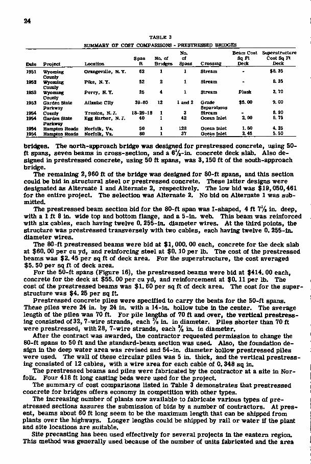
T A B L E 3 SUMMARY OF COST COMPARISONS - PRESTRESSED BRIDGES
Date Project Location Span
ft No. of Bridges
No. of
Spans Crossing
Beam Cost Sq Ft Deck
Superstructure Cost Sq Ft
Deck
1951 Wyoming Orangeville, N. Y . 62 1 1 Stream - $8.35 County
&35 1952 Wyoming Pike, N.Y. 32 2 1 Stream - &35 County
2.70 1953 Wyoming Perry, N.Y. 25 4 1 Stream Plank 2.70 County
$5.00 9.00 1953 Garden State Atlantic City 39-60 12 1 and 2 Grade $5.00 9.00 Parkway Separations
6.90 1954 County Trenton, N .J . 18-29-18 1 3 Stream - 6.90 1954 Garden State Egg Harlwr, N. I. 40 1 42 Ocean Inlet 2.00 6. 75
Parkway 4.25 1954 Hampton Roads Norfolk, Va. SO 1 128 Ocean Inlet 1. 60 4.25
1954 Hampton Roads Norfolk, Va. 80 1 37 Ocean Inlet 2.45 5. 50
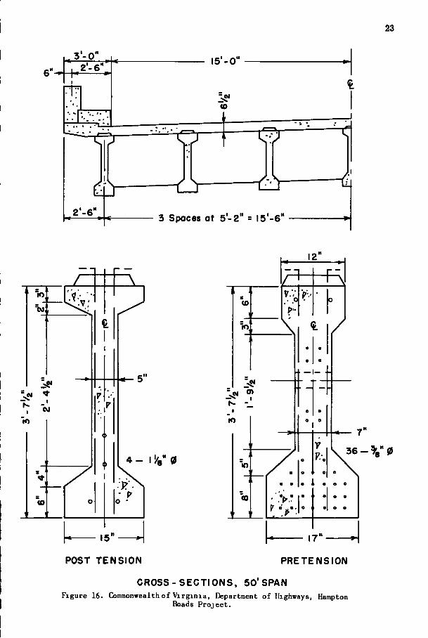
brieves. The north-approach bridge was designed for prestressed concrete, using 50-ft spans, seven beams in cross-section, and a 6y2-in. concrete deck slab. Also designed in prestressed concrete, using 50 ft spans, was 3,150 ft of the south-approach bridge.
The remaining 2,960 ft of the bridge was designed for 80-ft spans, and this section could be bid in structural steel or prestressed concrete. These latter designs were designated as Alternate 1 and Alternate 2, respectively. The low bid was $19,050,461 for the entire project. The selection was Alternate 2. No bid on Alternate 1 was submitted.
The prestressed beam section bid for the 80-ft span was I-shaped, 4 ft 1% in. deep, with a 1 ft 8 in. wide top and bottom flange, and a 5-in. web. This beam was reinforced with six cables, each having twelve 0. 255-in. diameter wires. At the third points, the structure was prestressed transversely with two cables, each having twelve 0. 255-in. diameter wires.
The 80-ft prestressed beams were bid at $1,000. 00 each, concrete for the deck slab at $60. 00 per cu yd, and reinforcing steel at $0.10 per lb. The cost of the prestressed beams was $2.45 per sq ft of deck area. For the superstructure, the cost averaged $5. 50 per sq ft of deck area.
For the 50-ft spans (Figure 16), the prestressed beams were bid at $414. 00 each, concrete for the deck at $55. 00 per cu yd, and reinforcement at $0.11 per lb. The cost of the prestressed beams was $1. 60 per sq ft of deck area. The cost for the superstructure was $4. 25 per sq ft.
Prestressed concrete piles were specified to carry the bents for the 50-ft spans. These piles were 24 in. 24 in. with a 14-in. hollow tube in the center. The average length of the piles was 70 ft. For pile lengths of 70 ft and over, the vertical prestress-ing consisted of 32, 7-wire strands, each % in. in diameter. Piles shorter than 70 ft were prestressed, with 28, 7-wire strands, each '/g in. in diameter.
After the contract was awarded, the contractor requested permission to change the 80-ft spans to 50 ft and the standard-beam section was used. Also, the foundation design in the deep water area was revised and 54-in. diameter hollow prestressed piles were used. The wall of these circular piles was 5 in. thick, and the vertical prestress-ing consisted of 12 cables, with a wire area for each cable of 0.348 sq in.
The prestressed beams and piles were fabricated by the contractor at a site in Norfolk. Four 418 ft long casting beds were used for the project.
The summary of cost comparisons listed in Table 3 demonstrates that prestressed concrete for bridges offers economy in competition with other types.
The increasii^ number of plants now available to fabricate various types of prestressed sections assures the submission of bids by a number of contractors. At present, beams about 60 ft long seem to be the maximum length that can be shipped from plants over the highways. Longer lengths could be shipped by rail or water if the plant and site locations are suitable.
Site precasting has been used effectively for several projects in the eastern region. This method was generally used because of the number of units fabricated and the area
25
available for stockpiling. The relative cost of renting a large area near the project for site prestressing may in many cases prove more economical from the contractors' standpoint than using a plant where storage facilities are limited.
Standardization of prestressed units seems to be the trend at the present time. In the near future, it should be possible to purchase prestressed bridge units for various span lengths in beam and slab sections.
The scheme used on the Garden State Parkway bridges opens the field to further standardization of such sections. For short span bridges, prestressed solid and hollow slab sections will be available at fabrication plants for various spans and loading conditions. The recent floods in the east, where many bridges were washed out, demonstrated the need for units to replace such bridges in the shortest possible time.
From the construction stanc^oint, prestressed units offer an efficient and economical solution for bridge replacement Through the medium of prestressed slab units, it is possible to replace an old bridge while maintaining traffic during construction.
On the longer spans, the use of prestressed concrete eliminates many of the problems with camber, when a partial width of the roadway is constructed in one operation. The need for building a variable haunch in the formwork for the deck slab is also el iminated. Since the prestressed girder is stiffer than other composite types and deflections are less, the need for falsework during construction is eliminated and vibration from traffic is less noticeable to pedestrians.
Much work remains to be done in the field of prestressing continuous structures, both in the design theory and construction. The possibilities of this method for long-span bridges seems promising. Today, contractors are bidding on prestressed designs with the same acceptance as other conventional designs. Like any new construction material or method, prestressed concrete must demonstrate its capabilities above and beyond its normal function before its full potential is exploited.
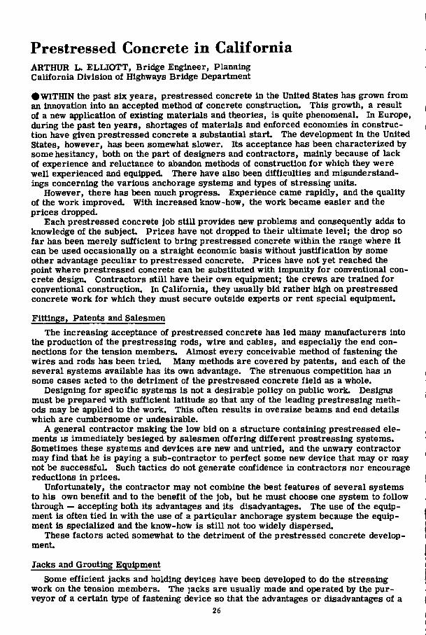
Prestressed Concrete in California ARTHUR L . E L L I O T T , Bridge Engineer, Planning California Division of Highways Bridge Department
• W I T H I N the past six years, prestressed concrete in the United States has grown from an innovation into an accepted method of concrete construction. This growth, a result of a new application of existing materials and theories, is quite phenomenal. In Europe, during the past ten years, shortages of materials and enforced economies in construction have given prestressed concrete a substantial start. The development in the United States, however, has been somewhat slower. Its acceptance has been characterized by some hesitancy, both on the part of designers and contractors, mainly because of lack of experience and reluctance to abandon methods of construction for which they were well experienced and equipped. There have also been difficulties and misunderstandings concerning the various anchorage systems and types of stressing units.
However, there has been much progress. Experience came rapidly, and the quality of the work improved. With increased know-how, the work became easier and the prices dropped.
Each prestressed concrete job still provides new problems and consequently adds to knowledge of the subject Prices have not dropped to their ultimate level; the drop so far has been merely sufficient to bring prestressed concrete within the range where it can be used occasionally on a straight economic basis without justification by some other advantage peculiar to prestressed concrete. Prices have not yet reached the point where prestressed concrete can be substituted with impunity for conventional concrete design. Contractors still have their own equipment; the crews are trained for conventional construction. In California, they usually bid rather high on prestressed concrete work for which they must secure outside experts or rent special equipment.
Fittings, Patents and Salesmen
The increasing acceptance of prestressed concrete has led many manufacturers into the production of the prestressing rods, wire and cables, and especially the end connections for the tension members. Almost every conceivable method of fastening the wires and rods has been tried. Many methods are covered by patents, and each of the several systems available has its own advantage. The strenuous competition has in some cases acted to the detriment of the prestressed concrete field as a whole.
Designing for specific systems is not a desirable policy on public work. Designs must be prepared with sufficient latitude so that any of the leading prestressing methods may be applied to the work. This often results in oversize beams and end details which are cumbersome or undesirable.
A general contractor making the low bid on a structure containing prestressed elements I S immediately besieged by salesmen offering different prestressing systems. Sometimes these systems and devices are new and untried, and the unwary contractor may find that he is paying a sub-contractor to perfect some new device that may or may not be successful. Such tactics do not generate confidence in contractors nor encourage reductions in prices.
Unfortunately, the contractor may not combine the best features of several systems to his own benefit and to the benefit of the job, but he must choose one system to follow through — accepting both its advantages and its disadvantages. The use of the equipment is often tied in with the use of a particular anchorage system because the equipment is specialized and the know-how is still not too widely dispersed.
These factors acted somewhat to the detriment of the prestressed concrete development.
Jacks and Grouting Equipment
Some efficient jacks and holding devices have been developed to do the stressing work on the tension members. The jacks are usually made and operated by the purveyor of a certain type of fastening device so that the advantages or disadvantages of a
26
27
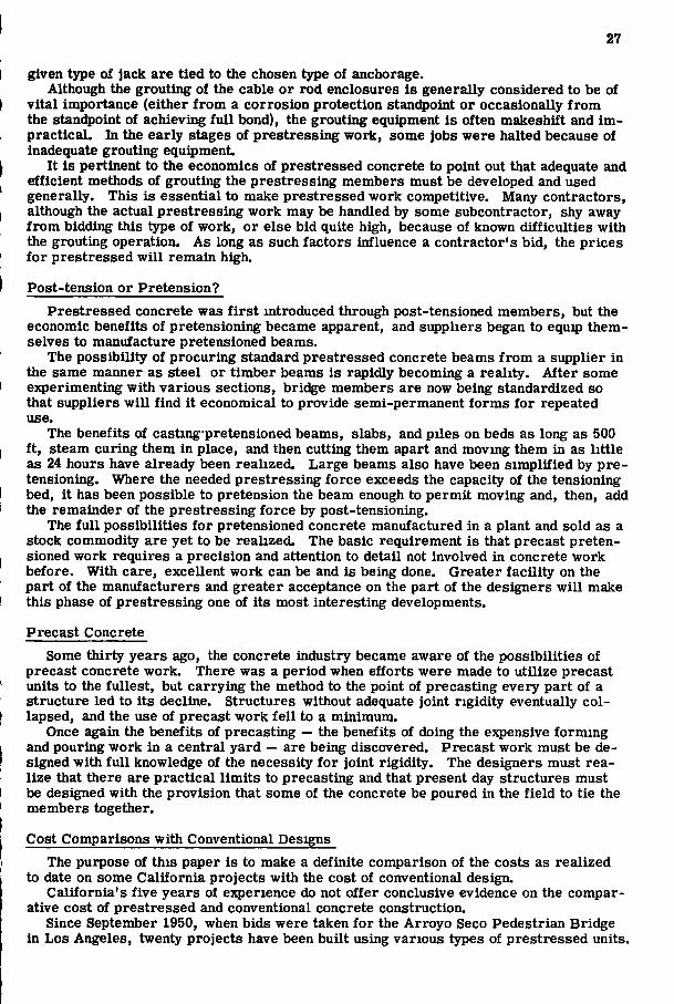
given type of jack are tied to the chosen type of anchorage. Although the grouting of the cable or rod enclosures is generally considered to be of
vital importance (either from a corrosion protection stanc^oint or occasionally from the standpoint of achievii^ full bond), the grouting equipment is often makeshift and im-practicaL In the early stages of prestressing work, some jobs were halted because of inadequate grouting equipment.
It is pertinent to the economics of prestressed concrete to point out that adequate and efficient methods of grouting the prestressing members must be developed and used generally. This is essential to make prestressed work competitive. Many contractors, although the actual prestressing work may be handled by some subcontractor, shy away from bidding this type of work, or else bid quite high, because of known difficulties with the grouting operation. As long as such factors influence a contractor's bid, the prices for prestressed will remain high.
Post-tension or Pretension?
Prestressed concrete was f irst mtroduced through post-tensioned members, but the economic benefits of pretensioning became apparent, and suppliers began to equip themselves to manufacture pretensioned beams.
The possibility of procuring standard prestressed concrete beams from a supplier in the same manner as steel or timber beams is rapidly becoming a reality. After some experimenting with various sections, bridge members are now being standardized so that suppliers will find it economical to provide semi-permanent forms for repeated use.
The benefits of castmg pretensioned beams, slabs, and piles on beds as long as 500 ft, steam curing them in place, and then cutting them apart and moving them in as little as 24 hours have already been realized. Large beams also have been simplified by pretensioning. Where the needed prestressing force exceeds the capacity of the tensioning bed, it has been possible to pretension the beam enough to permit moving and, then, add the remainder of the prestressing force by post-tensioning.
The full possibilities for pretensioned concrete manufactured in a plant and sold as a stock commodity are yet to be realized. The basic requirement is that precast pretensioned work requires a precision and attention to detail not involved in concrete work before. With care, excellent work can be and is being done. Greater facility on the part of the manufacturers and greater acceptance on the part of the designers will make this phase of prestressing one of its most interesting developments.
Precast Concrete
Some thirty years ago, the concrete industry became aware of the possibilities of precast concrete work. There was a period when efforts were made to utilize precast units to the fullest, but carrying the method to the point of precasting every part of a structure led to its decline. Structures without adequate joint rigidity eventually collapsed, and the use of precast work fell to a minimum.
Once again the benefits of precasting — the benefits of doing the expensive forming and pouring work in a central yard — are being discovered. Precast work must be designed with full knowledge of the necessity for joint rigidity. The designers must realize that there are practical limits to precasting and that present day structures must be designed with the provision that some of the concrete be poured in the field to tie the members together.
Cost Comparisons with Conventional Designs
The purpose of this paper is to make a definite comparison of the costs as realized to date on some California projects with the cost of conventional design.
California's five years of experience do not offer conclusive evidence on the comparative cost of prestressed and conventional concrete construction.
Since September 1950, when bids were taken for the Arroyo Seco Pedestrian Bridge in Los Angeles, twenty projects have been built using various types of prestressed units.
28
Approximately the same number of projects are being designed for construction within the next three years.
Prices are available for the twenty completed structures, and an attempt has been made to compare each prestressed concrete structure with a similar structure of conventional design. These twenty structures are composed of a variety of types of prestressed elements. The twenty projects were divided as follows:
Number of Structures Prestressing Application 2 pedestrian overcrossings T-shaped girders 1 pedestrian overcrossing Slab 6 structures T-shaped girders 1 structure Inverted T-section 2 structures I-shaped girders 3 structures Precast channel sections 1 undercrossing Slab 2 structures Box girders 2 miscellaneous structures Caps and beams
Prestressed concrete is not practical in all situations. Like all other materials, there are special advantages of the system which make it better in one situation than in another. It is of special interest, therefore, to analyze the reasons for selection of prestressed concrete designed for these various structures.
In seven of the cases, prestressed and precast concrete was chosen so that the beams could be swung into place either over water or over traffic with a minimum of interference. Economy and elimination of falsework were the main benefits.
In six cases, the prestressed design was chosen for separation structures to reduce the depth of the member to a minimum and to maintain the maximum clearance between roadway grades. Precast and prestressed construction was chosen in three cases because of the advantages and saving made possible by the mass production of a large number of similar units. Another savmg is to be found in construction without falsework.
Three more bridges were made precast and prestressed because of their remote location. It was more economical to precast the elements of the bridge at a plant and haul them out to the job than i t would have been to transport al l of the component parts and the labor.
The inherent characteristics of prestressing made it suitable for the twentieth structure. A bridge which was to be loaded with three feet of superimposed f i l l was bolstered up underneath with prestressed beams. The prestressing of the supplementary beams created a camber which brought them into f i r m contact with the ordinal structure, enabling them to take their Intended share of the increased load. This characteristic is also being used in several other structures now being designed. It is far super-ier to wedging or dry-packing with grout.
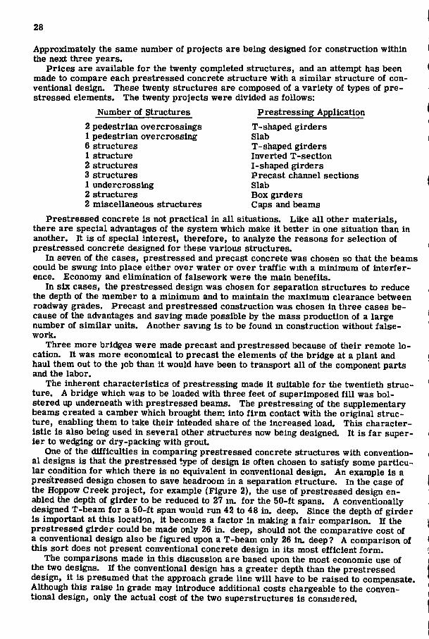
One of the difficulties in comparing prestressed concrete structures with conventional designs is that the prestressed type of design is often chosen to satisfy some particular condition for which there is no equivalent in conventional design. An example is a prestressed design chosen to save headroom in a separation structure. In the case of the Hoppow Creek project, for example (Figure 2), the use of prestressed design enabled the depth of girder to be reduced to 27 in. for the 50-ft spans. A conventionally designed T-beam for a 50-ft span would run 42 to 48 in. deep. Since the depth of girder is important at this location, it becomes a factor in making a fair comparison. If the prestressed girder could be made only 26 in. deep, should not the comparative cost of a conventional design also be figured upon a T-beam only 26 in. deep ? A comparison of this sort does not present conventional concrete design in its most efficient form.
The comparisons made in this discussion are based upon the most economic use of the two designs. If the conventional design has a greater depth than the prestressed design, it is presumed that the approach grade line wi l l have to be raised to compensate. Although this raise in grade may introduce additional costs chargeable to the conventional design, only the actual cost of the two superstructures is considered.
PbwBTRgea tD
Bocon S+. UndwcroMing iv-eF-«s-»rW
COMPARISON
C o W V N T I O N t l l -
Hupolbvl'icQl Similar Dasign
6114 sqft
*4o,5ao.
a\dt rcc'd- 5 99
S P A N S
A R E A O F O e C K
C O S T O F S U P B R S T R U C T U R B
C O S T P B R 8Q F T
CZ'-O"
*40.250. • G . 5 8
ertCollR»rnio Loco+ioo Code> CH uai) Di>fneV)-(Caunti))-(Bou4«)-(See4ion}.
Figure 1.
29
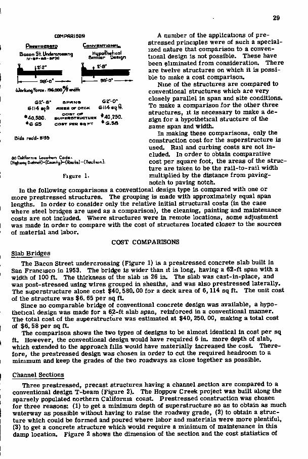
A number of the applications of pre-stressed principles were of such a specialized nature that comparison to a conventional design is not possible. These have been eliminated from consideration. There are twelve structures on which i t is possible to make a cost comparison.
Nine of the structures are compared to conventional structures which are very closely parallel in span and site conditions. To make a comparison for the other three structures, i t is necessary to make a design for a hypothetical structure of the same span and width.
In making these comparisons, only the construction cost for the superstructure is used. Rail and curbing costs are not included. In order to obtain comparative cost per square foot, the areas of the structure are taken to be the rai l- to-rai l width multiplied by the distance from paving-notch to paving notch.
In the following comparisons a conventional design type is compared with one or more prestressed structures. The grouping is made with approximately equal span lengths. In order to consider only the relative initial structural costs (in the case where steel brieves are used as a comparison), the cleaning, painting and maintenance costs are not included. Where structures were in remote locations, some adjustment was made in order to compare with the cost of structures located closer to the sources of material and labor.
COST COMPARISONS Slab Bridges
The Bacon Street undercrossing (Figure 1) is a prestressed concrete slab built in San Francisco in 1953. The bridge is wider than i t is long, having a 62-ft span with a width of 100 f t . The thickness of the slab is 26 in. The slab was cast-in-place, and was post-stressed using wires grouped in sheaths, and was also prestressed laterally. The superstructure alone cost $40,580.00 for a deck area of 6,114 sq f t . The unit cost of the structure was $6. 65 per sq f t .
Since no comparable brieve of conventional concrete design was available, a hypothetical design was made for a 62-ft slab span, reinforced in a conventional manner. The total cost of the superatructure was estimated at $40, 250. 00, making a total cost of $6. 58 per sq f t .
The comparison shows the two types of designs to be almost identical in cost per sq f t . However, the conventional design would have required 6 in. more depth of slab, which extended to the approach f i l l s would have materially increased the cost. Therefore, the prestressed design was chosen in order to cut the required headroom to a minimum and keep the grades of the two roadways as close together as possible.
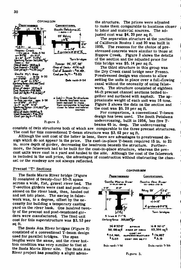
Channel Sections Three prestressed, precast structures having a channel section are compared to a
conventional design T-beam (Figure 2). The Hoppow Creek project was built along the sparsely populated northern California coast. Prestressed construction was chosen for three reasons: (1) to get a minimum depth of superstructure so as to obtain as much waterway as possible without having to raise the roadway grade, (2) to obtain a structure which could be formed and poured where labor and materials were more plentiful, (3) to get a concrete structure which would require a minimum of maintenance in this damp location. Figure 2 shows the dimension of the section and the cost statistics of
30
55
3-'S5
Hoppou Croak l - D N ^ - A &ids.4-
a.S" | . 7 " t«5'V ^,
Bou+« ZO/i Sep
l -HUM- l . B I D S
Oru Crack Canal
s . r a,.9" -l-a"
- l - k M - , 5 Qirdera 9 B'-O
COMPARISON the structure. The prices were adjusted to make them comparable to locations closer
ft^^^^^h- Soutb^RstalutnaUC to labor and material sources. The ad-^ ^ ^ ^ K A 'w^Z \ jiisted cost was $4. 29 per sq f t . • H °- i6%" 1 '^^'^ separation structure at the junction H • B H M M H H H ' ^ . of California Routes 1 and 20 was built in
1955. The reasons for the choice of pre-stressed concrete were similar to those at Hoppow Creek. Figure 2 shows the details of the section and the adjusted price for this bridge was $5.14 per sq f t .
The third structure in this group was the Dry Creek canal bridge near Fresno. Prestressed design was chosen to allow setting the units in place over a full-flowing canal without the necessity of using falsework. The structure consisted of eighteen 44-ft precast channel sections bolted together and surfaced with asphalt. The approximate weight of each unit was 16 tons. Figure 2 shows the data on the section and the cost was $5. 28 per sq f t .
For comparison, a conventional T-beam design has been used. The South Petaluma
FiKure 2 undercrossing, built in 1954, has five T-^ ' beams 45 in. deep. The undercrossing
consists of twin structures both of which are comparable to the three precast structures. The cost for this conventional T-beam structure was $3. 63 per sq f t .
Although the unit cost of the latter is less, there are advantages to prestressed design which do not appear in the price. The cast-in-place T-beam required 15 in. to 21 in. more depth of girder, decreasing the headroom beneath the structure. Furthermore, the falsework had to be built for the cast-in-place structure, whereas the precast units were cast in a yard and hauled to the site. Although the cost of the falsework is included in the unit price, the advantages of construction without obstructing the channel or the roadway are not always reflected.
Tuin bridgss Spons. 26,52'. 36'
Area oP Deck' 4174 sqff CodePSupifstr'ViaS. CosfporSnft. *3.6a
bids r«<Ai>S--S4
* (odj) — Prieas brslruciunis in reman locations have been reduced -to make -them comparable -b kiorticm cloMr -te labor and imbnol
sources
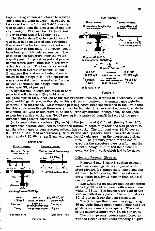
Precast "T" Sections The Santa Maria River bridge (Figure
3) consisted of twenty-four 50-ft spans across a wide, flat, gravel river bed. The T-section girders were cast and post-ten-sioned on the river bank, then, hauled out and set into place. The saving in falsework was, to a degree, offset by the necessity for building a temporary casting yard on the river bank. One hundred twenty of the precast and post-tensioned girders were manufactured. The final unit cost for this superstructure was $3. 53 per sqf t .
The Santa Ana River bridges (Figure 3) consisted of a conventional T-beam design used for parallel bridges. The span lengths were the same, and the river bottom condition was very similar to that at the Santa Maria River site. The Santa Ana River project has possibly a slight advan-
COMPARISON
PRCSTHCaSBP CoNVENTLOWfll-
Son-fa flno Rivwr V I I - O R A - I 1 B - B
San-fa Maria River
Rduu 28
4airxierae9'-0'«
Tiuin bridges 5 linese 7^r%
iWking-feree 359,000%r
24®50'-0' a P A N S I6®50'-0" 38.l96ai)lt n R E A o P D E c K 59,384 s^(r
* 134,960. s u P m T R u c T U B e *l7e.C97 • 3.53 C O S T P E R 9Q F T * 3.19
Bia» ric'd . 7-'S4 bids rec'd- 7-'53
Figure 3.
31
tage m being somewhat closer to a large labor and material source. However, in this case the conventional T-beam design was cheaper than the prestressed and precast design. The cost for the Santa Ana River project was $3.19 per sq f t .
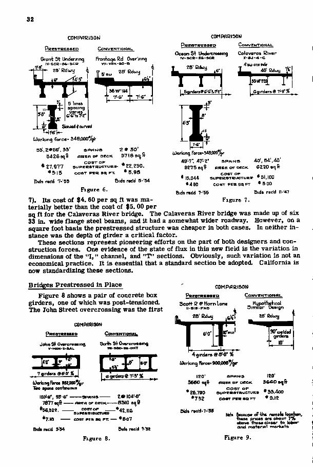
The Richardson Bay bridge (Figure 4) was built over an arm of San Francisco Bay where the bottom was covered with a thick layer of thin mud. Falsework would have been prohibitively expensive. The portion of the structure over the water was designed for prestressed and precast beams which were lifted into place from a derrick barge. The beams were cast in a yard which had water access to San Francisco Bay and were hauled about 40 miles to the brieve site. The operation was successful, and the unit cost for the precast portion of the bridge over the water was $3. 94 per sq f t .
A hypothetical design was made to compare to the Richardson Bay bridge, with
C O M P A R I S O N
Richordsen Bau brtdae I V - M R N - I - C
CowveNTioNtiu
Sitn HLfpolbslicol
'uiftldsd girdcra
15 girders® &-0' % (Jorking Fbro- 5e7.800^
40'
i seao ' 129,525 «) (fr
* 510,860. *3.94
Bids rccd 7--54
Rooduaij Section
f I R S A O F D V C K .
C O S T O K S U P B R S T R U C T U R B
C O S T P S R » 4 F T
18® 80' 129,525 8< ft
* 595.050 • 4.59
Figure 4.
the presumption that, because of the falsework difficulties, it would be necessary to use steel welded girders even though, in this salt water location, the maintenance painting cost would be increased. Maintenance painting costs were not included in the unit costs for this study even though these costs must be included in an over-all economic study to determine the type of structure to be used. The hypothetical design cost, based upon prices for similar work, was $4. 59 per sq f t , a material benefit in favor of the prestressed and precast construction.
In the separation structure (Figure 5) at the junction of California Routes 5 and 107, prestressed section was used to obtain the minimum depth of girder and was precast to get the advantages of construction without falsework. The unit cost was $6. 00 per sq f t . The Collier Road overcrossmg, with welded steel girders and a concrete deck had a unit cost of $5. 09 per sq f t and was considerably cheaper than the prestressed struc
ture. The primary probelm was one of erecting the structure over traffic, and the T-beam design minimized the amount of concrete form work which had to be done.
K R g S T H C S S g Q
Rbu4e \m/a Sep. I V - A L A - S . I O T - B
COMPARISON CowvefJTiowai.
28' EduHj
Collier Road Overcressinq X - S J - 4 - D ^
2&-Bdui) I • 7' . s'sw
4'-3'
f '40'(<)eldedSUl6ire
8"-9'
f (Oorking farce-42a000%r
2 » e r 4Ze5s (V
•26,590. *6 00
Bids r«c'd 3-'5S
S P A N S 32', zees', 32' fteen O P OECK. (O285 s^ft-
C O S T O F S U P E R S T R U C T U R C
C O S T P E R S Q r - T
Figure 5.
'51,973. *5.09
Ciids rec'd I-'55
I-Section Precast Girders Figures 6 and 7 show I-section precast
and prestressed girders compared with steel girders for comparable spans and conditions. In both cases, the precast concrete beam is slightly deeper than its steel counterpart.
The Grant Street undercrossing consisted of five girders 42 in, deep with a maximum width of 18 in. The beams were cast at the site and lifted into place. The unit cost was $5.15 per sq f t for the superstructure.
The Frontage Road overcrossing, using 36 in. wide flange steel beams, also had five girders and comparable spans. The cost of the superstructure was $5. 98 per sq f t .
The other precast prestressed I-section was the Ocean Street undercrossing (Figure
32
ESTRESSgP
COMPflEISOIv)
C o N V E N T I O r O m .
COMPflRISOlO
Grant 3t Underxing IV-SCe-9fa-SCB
Fronfaqe Ed Over'xing V I I - V E N - a O - S
5 lines spocing
28 eduij
36WFI94
OcBOnS+ UndareroMing i v - s c e - s e - s c R
28' Bduy
C o N V E N T I C
Calaveras Siver
. 4'8ii) oni side 40' BduiB
.5qird«r»»g-6''t.7'2'i I
Sk«u«d*cun«d T^l ' -6 ' l -
tiiorking -force-
03',2»59', 33' 5426 39 A
*?7,977 * 5 I 5
Bid* rwtfd 7-55
S P A M S 2 » 50'
f l B E n OF D E C K 3716 ft
C O S T O F ^ S U P B R O T R U C T U R E - '22.250.
(forking ForccMe.OOD' 49'-7", 47!-Z- S P A N S 40', 54',40'
3275s()ff flREn OF D E C K e220si^R'
* 15.044 •460
bids redd 7-55 Bids r»(?d n-'47 Figure 7.
C O S T O F S U P B R S T R U C T U R R
C O S T P E R SQ F T
* 31.100 • 5 00
C O S T P E R 9Q F T . * 5.98
Bids rcc'd 5-'54
Figure 6.
7). Its cost of $4. 60 per sq f t was materially better than the cost of $5.00 per sq f t for the Calaveras River bridge. The Calaveras River bridge was made up of six 33 in. wide flange steel beams, and i t had a somewhat wider roadway. However, on a square foot basis the prestressed structure was cheaper in both cases. In neither instance was the depth of girder a critical factor.
These sections represent pioneering efforts on the part of both designers and construction forces. One evidence of the state of flux in this new field is the variation in dimensions of the " I , " channel, and "T" sections. Obviously, such variation is not an economical practice. I t is essential that a standard section be adopted. California is now standardizing these sections.
Bridges Prestressed in Place Figure 8 shows a pair of concrete box
girders, one of which was post-tensioned. The John Street overcrossing was the f i r s t
COMPARISON
PwgSTRgaaeD CoMvEi«nor«iii.
John Sf OvKTcroaaing V-MON-a-ftAL
3udh Sf OvBTcrsseina •m-SBo-as-oHT
7flird«fa 9tt-V%^
(i)arkingFiire« 952La00%r 1aio spans eonfinueus
69ird«r3e7-5-%
loo^e', ss'-e' 7877 s^fi —
•56,522. — *7.I8
Bidsrae'd 9 54
S P A N S - A R E A OP D B C K -
2 9 l04'-0'' -S5I0 s^ff
_ C O S T O F | , g
COST PES 9Q FT. * 5 0 7
Bids reed 7--9Z
Figure 8.
COMPflBISON p R B e r R g s s e o COMVBWTIONWI-
icol Scot)- B 9 Horn Lone l l - S I S - F A S
Hijpof b r f 11 Similar Design
28' I2duiy 28'l2duiu
4girtlar9 SS'-O" % hXsrking iwca-900.0eoygir
120' 3660
S P A N S
A R E A O F O E C K
120"
J. C O S T O F * . •26.790 S U P B R S T R U C T U R B • 33.4oO
•732 COBTT P B R S Q F T * 9.12
Bids rccd<7-'99 Noh BccoioB oFtiw ramets IseaW -these prices ore about 7% above those closer to kiber and mot»rial markets
Figure 9.
33
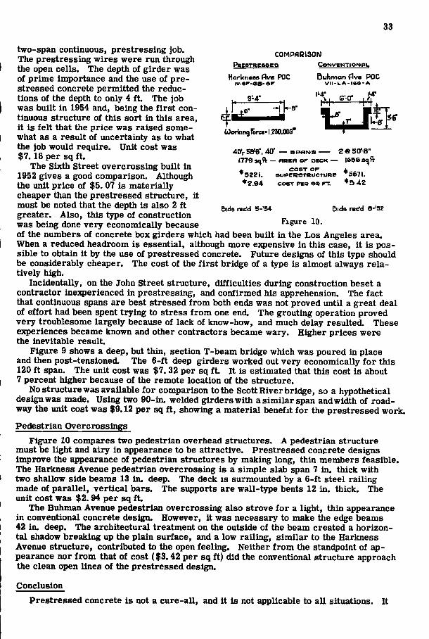
COMPARISON PBEaTRgaaco C O N V E N T I O N B I -
Harlcneas Ave POC iv-sp-es- sF
9 4-
5uhman<^va POC vii-LA-iae-A
6i}orkin9rorc*-I.Z30.00(r
40'- Baser. 40' — S P A N S — 2 ® so'-b"
lT79a<^ft — ftatsa or D E C K — 165Sa<|(t
•Z.94
C O S T o r ^ S U P E R S T B U C T U R B S67I.
• 5 42 COOT P E B FT.
e>ids ndd 5-'54 Bids ndd e-'SZ
two-span continuous, prestressing job. The prestressing wires were run through the open cells. The depth of girder was of prime importance and the use of prestressed concrete permitted the reductions of the depth to only 4 f t . The job was built in 1954 and, being the f i r s t continuous structure of this sort in this area, it is felt that the price was raised somewhat as a result of uncertainty as to what the job would require. Unit cost was $7.18 per sq f t .
The Sixth Street overcrossing built in 1952 gives a good comparison. Although the unit price of $5. 07 is materially cheaper than the prestressed structure, it must be noted that the depth is also 2 f t greater. Also, this type of construction was being done very economically because Figure 10. of the numbers of concrete box girders which had been built in the Los Angeles area. When a reduced headroom is essential, although more expensive in this case, i t is possible to obtain i t by the use of prestressed concrete. Future designs of this type should be considerably cheaper. The cost of the f i r s t bridge of a type is almost always relatively high.
Incidentally, on the John Street structure, difficulties during construction beset a contractor inexperienced in prestressing, and confirmed his apprehension. The fact that continuous spans are best stressed from both ends was not proved until a great deal of effort had been spent trying to stress from one end. The grouting operation proved very troublesome largely because of lack of know-how, and much delay resulted. These experiences became known and other contractors became wary. Higher prices were the inevitable result.
Figure 9 shows a deep, but thin, section T-beam brieve which was poured in place and then post-tensioned. The 6-ft deep girders worked out very economically for this 120 f t span. The unit cost was $7. 32 per sq f t . It is estimated that this cost is about 7 percent higher because of the remote location of the structure.
No structure was available for comparison to the Scott River bridge, so a hypothetical design was made. Using two 90-in. welded girders with a similar span and width of roadway the unit cost was $9.12 per sq f t , showing a material benefit for the prestressed work.
Pedestrian Overcrossings Figure 10 compares two pedestrian overhead structures. A pedestrian structure
must be light and airy in appearance to be attractive. Prestressed concrete designs improve the appearance of pedestrian structures by making long, thin members feasible. The Harkness Avenue pedestrian overcrossing is a simple slab span 7 in. thick with two shallow side beams 13 in. deep. The deck is surmounted by a 6-ft steel railing made of parallel, vertical bars. The supports are wall-type bents 12 in. thick. The unit cost was $2.94 per sq f t .
The Buhman Avenue pedestrian overcrossing also strove for a light, thin appearance in conventional concrete d e s ^ However, i t was necessary to make the edge beams 42 in. deep. The architectural treatment on the outside of the beam created a horizontal shadow breaking up the plain surface, and a low railing, similar to the Harkness Avenue structure, contributed to the open feeling. Neither from the standpoint of appearance nor f rom that of cost ($3.42 per sq ft) did the conventional structure approach the clean open lines of the prestressed design.
Conclusion Prestressed concrete is not a cure-all, and it is not applicable to all situations. It
34
has certain advantages which may give benefits not reflected in unit costs. It permits the construction of long beams which may be lifted into place without the necessity for falsework or for interruption of traffic beneath a structure. It permits more slender and shallow members, allowing greater headroom and decreasing the required depth of a structure. It permits a member to be built in place and then post-tensioned to take its share of the load. When pretensioned, it permits members to be built economically in yards and hauled to the structure site.
It has little advantage on very short spans. It raises the difficulty of tying together precast concrete members. It calls for precision of workmanship beyond that usually found in concrete construction. It requires specialized knowledge and special techniques and equipment. It demands a certain amount of experience and know-how. This last reason has been outstanding in holding construction prices higher than warranted.
Prestressed concrete is a new medium with definite uses. Cost alone is not the entire answer, and cost of prestressed work wi l l decrease with time and experience. In the future, prestressed and precast beams wi l l be bought on the market as a standard stock item. An amalgamation of the various prestressing systems to promote prestressed concrete as a whole and to subdue detrimental competition is probable. The position of prestressed concrete in the construction field wi l l be clarified by these factors.
The time wi l l soon come when the engineer who considers the use of prestressed concrete wi l l find that, for the benefits derived and for the money expended, prestressed concrete adds a new, economical, and exciting medium to the many which the structural engineer may use.
ACKNOWLEDGMENT The author is indebted to William Yusavage of the Department Pricing Section for
compiling the comparative price figures.
HBB.0R-3S
TH E NATIONAL A C A D E M Y OF S C I E N C E S — N A T I O N A L R E S E A R C H C O U N C I L is a private, nonprofit organization of scientists, dedicated to the furtherance of science and to its use for the general welfare. The
A C A D E M Y itself was established in 1863 under a congressional charter signed by President Lincoln. Empowered to provide for all activities appropriate to academies of science, it was also required by its charter to act as an adviser to the federal government in scientific matters. This provision accounts for the close ties that have always existed between the A C A D E M Y and the government, although the A C A D E M Y is not a governmental agency.
The NATIONAL R E S E A R C H COUNCIL was established by the A C A D E M Y in 1916, at the request of President Wilson, to enable scientists generally to associate their efforts with those of the limited membership of the A C A D E M Y in service to the nation, to society, and to science at home and abroad. Members of the NATIONAL R E S E A R C H COUNCIL receive their appointments from the" i"esident of the ACADEMY. They include representatives nominated by u e major scientific and technical societies, representatives of the federal government designated by the President of the United States, and a number of members at large. In addition, several thousand scientists and engineers take part in the activities of the research council through membership on its various boards and committees.
Receiving funds from both public and private sources, by contribution, grant, or contract, the A C A D E M Y and its R E S E A R C H COUNCIL thus work to stimulate research and its applications, to survey the broad possibilities of science, to promote effective utilization of the scientific and technical resources of the country, to serve the government, and to further the general interests of science.
The H I G H W A Y R E S E A R C H BOARD was organized November 11, 1920, as an agency of the Division of Engineering and Industrial Research, one of the eight functional divisions of the NATIONAL R E S E A R C H COUNCIL. The BOARD is a cooperative organization of the highway technologists of America operating under the auspices of the A C A D E M Y - C O U N C I L and with the support of the several highway departments, the Bureau of Public Roads, and many other organizations interested in the development of highway transportation. The purposes of the BOARD are to encourage research and to provide a national clearinghouse and correlation service for research activities and information on highway administration and technology.