Embed Size (px)
Citation preview

R 247 Philips Res. Rep. 9, 259-294, 1954
SOME INVESTIGATIONS ON THE ELECTRICALPROPERTIES OF HEXAGONAL SELENIUM *).
by L. M. NIJLAND 546.23: 548.1.023: 537
Summary
A short survey of the recent literature on seleniumis given in thefirst chapter. The resistivity of polycrystalline, hexagonal seleniumcan be loweredby halogens and can be raised by thallium. No reliabledata on fundamental quantities like hole densities and mobilities arefound in the literature. Investigations on these subjects are describedin the .next chapters. A method to purify seleniumby evaporationnear its melting point Is developed (chapter 11). High-frequencymeasurements of the conductivity of pure and of thallium-dopedselenium samples comply with the assumption that polycrystallineselenium consists of rather well-conducting crystals embedded inbadly conductinglayers of moreor less amorphous selenium. Thalliumincreases the resistance of the layers and does not or only slightlyaffect the resistance of the crystals (chapter Ill). Measurements ofthe Hall effect and of the shunt resistivity vs frequency of pureand of bromine-containing selenium samples point to the samelayer structure. Bromine does not affect the resistivity of crystalsbut lowers that of the layers. Single crystals prepared in a bromine-containing atmosphere have the same resistivities as pure crystalshave (chapter Ill). The last chapter contains a discussion of theexperimental results and points to a model with both amorphousand crystallized parts in the same selenium chain.
Résumé
Le premier chapitre contient un résumé de la littérature récemmentparue sur le sëlënium, La résistivité du sêlënium hexagonal poly-cristallin peut être abaissée par leshalogènes et ëlevëepar Ie thallium.L'on n'y pourra trouver aucune donnée sûre quant aux quantitësfondamentales comme les densitës et la mobilitë des trous. Desrecherches sur ces sujets sont décrites dans les chapitres suivants.Une méthode de purification du sëlënium par l'évaporation prèsde son point de fusion a ëtë dëveloppëe (chapitre 11). Les mesuresà haute fréquence de la conductivitê d'échantillons de sëlênium puret de sêlënium additionnés de thallium ont confirmé l'affirmationque Ie sëlënium polycristallin consiste en cristaux d'assez honneconductivité enrobés dans des couchesmal conductrices de sëlëniumplus ou moins amorphe. Le thallium augmente la résistance descouches et influence tout au plus légèrement la rësistancedes cristaux(ehapitre Ill). Les mesures de l'effet de Hall et de la résistivité deshunt en fonction de la fréquence d'échantillons de sêlênium purou additionnés de brome, indiquent la même structure de couche.Le brome n'affecte pas la résistivité des cristaux, mais abaisse celledes couches. Les monocristaux prëparës en atmosphère contenant dubrome ont les mêmes résistivités que les cristaux purs (chapitre Ill).Le dernier chapitre contient une discussion des résultats expérimen-taux et prescrit un modèle comprenant ensemble desparties amorpheset cristallisées dans la même. cbaine du sëlënium.
• ) Thesis, University of Amsterdam, April 1954.

260 L. M. NIJLAND
ZusammenfassungIm ersten Kapitel wird eine kurze Übersicht des jüugsten Schrifttumsüber Selen gegeben. Der Widerstand von polykristallinischem,hexagonalem Selen kann durch Halogene vermindert und durchThallium erhöht werden. Üher grundlegende Eigenschaften wieLöcherkonzentration und -heweglichkeit sind keine zuverlässigenDaten in der Literatur zu linden. Untersuchungen üher diese Fragenwerden in den folgenden Kapiteln beschrieben. Ein Verfahren zurReinigung von Selen durch Verdampfung nahe seinemSchmelzpunktwird in Kapitel 11 entwickelt. HF -Messungen der Leitfähigkeitreiner und thalliumhaltiger Selenproben bestätigen die Annahme, daBpolykristallinisches 'Selen hauptsächlich aus ziemlich gut leitendenKristallen besteht, die in schlecht leitenden Schichten von mehroder weniger amorphem Selen eingebettet sind. Thallium erhöht denWiderstand der Schichten und heeinfluBt nicht oder nur schwach denWidl'rstand der KristalIe (Kapitel lIl). Messungen des Hall-Effektesund des NehenschluB-Widerstandes als Funktion der Frequenz vonreinen und von hromhaltigcn Selenproben weisen auf dieselbe Schicht-struktur. Brom heeinfluût nicht den Widerstand von Kristallen, ver-mindert aber den der Schichten. In einer bromhaltigen Atmosphärebereitete Einkristalle weisen dieselhen Widerstände auf wic reineKristalIe (Kapitel Ill). Das letzte Kapitel enthält eine Erörterungder experimentellen Ergebnisse und deutet darauf hin, daB in einerSelenkette sowohlamorphe als auchkristallinische Teileenthalten sind.
INTRODUCTION
There are many problems found in the research on selenium rectifiers.The forward resistance of these rectifiers can he decreased by adding,for instance, halogens such as chlorine or bromine, or Iialides (such ashave been described in patent literature by Dr W. Ch. van Geel of thislaboratory already in 1936) to the selenium to he used; it is possible,according to patent literature, to stabilize a once gained high conductivityof the selenium by various other compounds. Almost all these additionshave one thing in common: it is not easy to find a suitable position for-these impurities in the selenium lattice. Thus it might be of interestto measure the density of electrical charge carriers both in pure and inimpurified selenium to trace its possible correlation with the density ofthe impurities. Such measurements might also give information on thelength of selenium chains in crystallized selenium, and on the whole, onthe mechanism of electrical conduction in selenium.Many other problems arise when investigating the possibilities of increas-
ing the quality of the current-voltage characteristic of a selenium rectifierin the inverse direction: patent literature describes a multitude of elementsand chemical compounds which, when applied under favourable conditions,should change the properties of the rectifier in 'the way desired.Thallium and its compounds are often used for this purpose: because not
only the electrical properties of the selenium surface, but also the bulk resistiv-ity of selenium are strongly influenced by thallium, the electrical propertiesof the system thallium-selenium seem to be extremely suitable for research.

ELECTRICAL PROPERTIES OF HEXAGONAL SELENIUM 261
The reader will find a résumé of the recent literature on the electricalproperties of selenium in chapter I. A purifying method for selenium isdescribed in chapter Il. Measurements of the conductivity, and of theHall effect of hoth pure selenium and selenium to which thalliu'm or hrominehas heen added, are discussed in chapter Ill. Chapter IV contains a dis-cussion of the results ohtained.
CHAPTER I
SURVEY OF THE RECENT LITERATUREON THE CRYSTALLOGRAPIDCAL PROPERTIES
AND THE ELECTRICAL CONDUCTIVITY OF SELENIUM
Because the literature on the electrical properties of selenium is noteasily accessible, a résumé of these properties seems to he appropriate.It will contain:(1) A description of the modifications of selenium.(2) A survey of their electrical properties, most of which will he devoted
to the mechanism of electrical conduction in hexagonai selenium.(3) A programme of investigations.The atomic weight of selenium is 78·96. The element hoils at 685°C!);
the melting point is not exactly known hut is, according to variousauthors, 219·5 °C ± 1·5 °C. A vapour-pressure diagram of the various formsof selenium is sketched in fig. 1 2).
_ temperuture 79643 :~.
Fig. 1. Vapour-pressure curves of the various forms of selenium. Temperajuree iiI'/(

262 L.M.NIJLAND
1. The modifications of selenium
Solid selenium appears in the following modifications:(1) Amorphousselenium (known in a red and in a black, "vitreous" form),(2) a-Monoclinië selenium. .'(3) p-Monoclinic selenium.(4) Hexagonal selenium.Ad (1). Vitreous selenium (spec. weight4·2 -4·4) canbe obtainedbyrapid
cooling of the melt. According to many investigations, among ~vhichthevery recent one of Richter, Kulcke and Specht 3), vitreous selenium isidentical with supercooled selenium.
Ad (2) and (3). A mixture of the two monoclinic forms can be preparedhy evaporation of the solvent from a solution of selenium in carbondisulphide. Burbank 4) and Marsh 5) found the selenium atoms in thesemodifications ordered to eight-membered rings.
Ad (4). Hexagonal (metallic or grey) selenium (spec. weight 4·81- 4·82) ismade up of parallel, spiralized chains of selenium atoms (fig. 2). Thisstable modification can be obtained from any of the other forms by heating.The mechanism of these transitions has heen described by De Boer 6).Molten selenium too is supposed to consist of long chains which may heentangled to coils, and perhaps also of poly-membered rings 6), '), B).The viscosity of this molten selenium increases rapidly with decreasingtemperature. Morsch 7) explains this by supposing an increase of themean chain length at decreasing temperatures. When cooled below 220 oe(the melting point of hexagonal selenium), the entanglement of longchains persists; this supercooled fluid is called "vitreous selenium", and
II
~®II
@--.,.I---- -- ---®:--,,/ ~ .
""..../'®-__"L<.::/ ~-.V'
A 0a",4.364.&c=4.959.&u= 0: =0.223
Fig. 2. The crystal structure of hexagonal selenium. The shortest distance between twoatoms in 'one chain is equal to 2·36 A; the shortest distance between two atoms inneighbouring chains is equal to 3·45 A.

ELECTRICAL PROPERTIES OF HEXAGONAL SELENIUlII 263·
shows a great deal of resemblance in structural and physical propertieswith plastic sulphur. By annealing this vitreous selenium some of thechains arrange themselves to a structure as occurring-in hexagonal selenium.The crystallization proceeds in this way and gives at Iastr polycrystalline .hexagonal selenium. It will be clear that the properties' of the ultimateproduct will be connected with its thermal history.
It is well known that small amounts of some impurities (halogens,phosphorus, arsenic) strongly affect the rate of crystallization. This maybe caused by a shortening or a branching of the chains in the melt andin the vitreous form.
Single crystals of hexagonal selenium can be prepared either by suhli-mation out of the vapour 9) or by very slow crystallization of the melt P].The first method almost always supplies hollow needles: the directionsof greatest lengths coincide with those of the hexagonal c-axis, The facesof these crystals are very seldom well-formed: twisting and twinningof the needles often occurs. Crystals out of the melt are often betterformed, but very small.
2. The electrical properties of selenium
(1) Molten and vitreous selenium
The resistivity of molten selenium is dependent on the temperatureand on the nature and quantity of the impurities 11),12),13). The behaviourof liquid selenium of rectifier quality or better is described by
Blog f2 = - A + -,
T
where f2 is the value of the resistivity in Q cm. A and B are constantsdependent on the type of selenium used:
3·5<A < 4,0, 5600 OK <B < 6000 oK for 520 oK < T < 770 oK,
so that the resistivity at 260°C will be about 107 Q cm.Many impurities, for instance the halogens and some halides such as
cerous iodide and selenium chloride, cause a large decrease of this resis-tivity: this property can be as low as some thousands Q cm. We foundthat the relation between the values of the resistivity e and of the brominecontent c is given by
log f2 = a - blog c
(a and b are parameters, dependent on the temperature) within a widerange of c-values,
Not much is known about the resistivity of vitreous selenium. At 20°C
264 L. M. NIJLAND
the resistivity is very high (1010 to 1014 n cm) and strongly dependenton the illumination.(2) Both .kinds of monoclinic selenium have got very high and light-dependent resistivities. Due perhaps to the small technical importance ofthese modifications, little more than their crystal structures are describedin Iiterature,
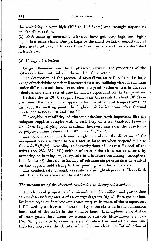
(3) Hexagonal selenium
Large differences must be emphasized between the properties of thepolycrystalline material and those of single crystals.
The description of the process of crystallization will explain the largerange of resistivities which will be found after crystállizing vitreous seleniumunder different conditions: the number of crystallization centres in vitreousselenium and their rate of growth will be dependent on the temperature.
Resistivities at 20 oe ranging from some thousands to about 105 n cmare found: the lower values appear after crystallizing at temperatures notfar from the melting point. the higher resistivities occur after thermaltreatment between 70 and 100 oe.
Thoroughly crystallizing of vitreous selenium with impurities like thehalogens supplies samples with a resistivity of a few hundreds n cm at I
20 oe 14); impurifying with thallium, however, can raise the resistivityof polycrystalline selenium to 109 n cm 15),16),17).
The conductivity of selenium single crystals in the direction of thehexagonal c-axis is three to ten times as large as when perpendicular tothis axis 18),19),20). According to investigations of Lehovec 21) and of thewriter (pp. 282, 287, 291) neither of these resistivities can be altered bypreparing or keeping single crystals in a bromine-containing atmosphere. I
It is known 19) that the resistivity of selenium single crystals is dependenton the applied field strength, this pointing to internal barriers.
The conductivity of single crystals is also light-dependent. Henceforthonly the dark-resistance will be discussed.
The mechanism of the electrical conduction in hexagonal selenium
The electrical properties of semiconductors like silicon and germaniumcan be discussed by means of an energy diagram (fig. 3). Pure germanium,for instance, is an intrinsic semiconductor; an increase of the temperatureis followed by an increase of the density of the electrons in the conductionband and. of the holes in the valence band. Isomorphous substitutionof some germanium atoms by atoms of suitable fifth-column elements(As, Sb) gives rise to donor levels just below the conduction band andtherefore increases the density of conduction electrons. Introduetion of

ELECTRICAi.. ::nOPERTIES OF HEXAGONAL SELENIUM 265
third-column elements (such as In or AI) causes acceptor levels nearabove the valence band and so increases the density of holes.A discussion on the mobility of these charge carriers {conduction
electrons and holes) in the lattice will be given in section (3d).Because such energy diagrams can be constructed only after studying
the density of charge carriers, many investigations are devoted to thissubject in connection with selenium. In most cases the carrier densityhas been calculated from the thermo-electric power 23),24),25). Plessner 26)estimated its value in a selenium single crystal from the Hall effect.Other measurements of the Hall effect of rather pure polycrystallineselenium have been published by Iglitsen 27), while Eekart and Kittel 28)succeeded in measuring the Hall effect of rather well-conducting seleniumlike that used in the manufacturing of selenium rectifiers (these authors,did not disclose any details on the composition or preparation of thesamples used).
Intrinsicsernit:onduc:1'ion
:i
by
excess semi-eenduetionan electron
an ac;:rtor. Ie-
defect semi-conduction
a hole
Conductionband
Extrinsic semiconduction
+
Valence-bond •band
The tran-sition otanelectron
from the valen-ce-bond band
from a donorlevel
from the I'Olen-ce -band band
to the cooductionband
mixed semi-conduction
an electron onda hole
the conductionband
causes
79645
Fig. 3. Energy diagrams for semiconductors.
According to Schottky 29) the density of carriers near the counter-electrode of a selenium rectifier can be calculated from the 'change ofthe rectifier capacity caused by the applied potentlal difference.
Summarizing the result of these authors:(1) The density of holes in selenium single crystals is about 1014 cm-3
(i.e. one carrier in 3.7.108 selenium atoms) and does not much dependon the temp~rature. The mobility of these carriers is equal to or less than1 cm2fV 'sec (which would be an extremely small value) according tod.c. measurements; h.f. measurements point to higher values.

266 L. 111.NIJLAND
(2) The electrical current is carried through polycrystalline selenium byholes with a density between 1014 and 1017 cm-a. This number woulddepend rather strongly on the temperature according to measurementsof the thermo-electric power, in contradiction to the estimates basedupon the Hall effect. The mobility of the holes is dependent on the impuritycontent and on the thermal treatment of the samples and may amountfrom 0·003' to 3 cm2fV sec.
3. Research programme
It is obvious that systematical investigations on the changes of thenumber of carriers in selenium by varying the activator content are stillnecessary. It seems reasonable to perform these experiments with bromine-containing selenium, so that the conductivity of the samples can reacha relatively high value. Direct information about the number of carrierscan be supplied by measurements of the Hall effect. Measurements ofthe thermo-electric power seem easier to perform. This physical quantity,however, varies rather slowly with the density of carriers; a relativelysmall change of the thermo-electric power should therefore be explainedby a considerable change in the carrier density, which fact might introduceimportant errors. The formulae for the relation between thermo-electricpower and carrier density, moreover, apply only for the idealized caseof free carriers in an isotropic medium, which is not always strictlynecessary for the application of the formulae for the Hall effect. See ref. 30)and section (3e).A second key to the problem could be offered by investigations on
selenium impurified with thallium. This metal can multiply the resistivityof hexagonal pure selenium by as much as a hundred thousandwithout a reasonable explanation being known 15),16),17). Samples withresistivities higher than a hundred thousand Q cm and mobilities as lowas one cm2fV sec or less are not suitable for measurements in conventionaldirect-current Hall circuits, so that other methods must be applied.Hoffman 31) estimated the carrier density near the thallium-containingcounter-electrode by the method of Schottky 29). In this way a holedensity (the word used was "Störstellendichte") in the order of 1016 cm-awas found. Assuming a resistivity of more than 106 Q cm for the layerof selenium near the electrode, a hole mobility of less than .10-3 cm2fV secwill be calculated. Such values are very improbable. The thermo-electricpower of selenium which contains traces of thallium cannot be measuredby a simple method; such thermo-elements have a very large internalresistance. Therefore we have chosen the. easier but less iIiformativemethod of measuring the high-frequency conductivity.
ELECTRICAL PROPERTIES OF HEXAGONAL SELENIUM 267
CHAPTER II
THE ,PURIFICATION OF SELENIUM
1. The purpose of the purifying process and disadvantages of chemicalmethods
Considerable information on the relation between the resistivity ofhexagonal selenium and its impurity content is found in literature. Itis known, for instance, that an appreciable lowering of the resistanceoccurs after adding 1 bromine atom to every I~5 selenium atoms; addingof 1 thallium atom to every 106 selenium atoms may multiply the resistivityof hexagonal selenium by two or more. Small amounts of many otherimpurities (sulphur, phosphorus, arsenic, sodium chloride and manyothers of the most differing kinds) may have an effect after a well-selectedthermal treatment. Investigations on the mechanism of electrical conduc-tivity in selenium must be preceded, therefore, by a purification of theselenium to be used, which should lead preferably to less than traceableamounts of all impurities."Selenium for rectifiers" (this containing on the average more than
99·9 % of selenium) may contain the following contaminations: P, 0,S, Te, Cl, Na, Mg, Ca, Al, Si, Mn, Fe, Ni, Sn, Zn, Cu, Ag, Pb, Hg. Some ofthese' (Te, Cl) occur "freely" in selenium, most of these impurities arebound; metals for instance are often found as sulphides or selenides. Thetraceable quantity (by means of spectrochemical or "wet" analyticalmethods) of each of these impurities may vary between about 1 atomto 104 and 1 atom to 107 selenium atoms.
When using a "wet" method, of purification, apparatus (glassware)and chemicals should be carefully checked; small amounts of impuritiesbeing present in the chemicals to be used are likely to be adsorbed onthe surface of precipitated selenium. Moreover applying solutions ofselenium or compöunds of this element means bringing comparativelylarge quantities of chemicals into close contact with the substance tobe purified, thus increasing its chance of becoming contaminated.
Chromatographical methods (used for instance with aluminium oxideas an adsorbent for the impurities in an aqueous solution of seleniumdioxide) increased the aluminium contents of the samples and decreasedinsignificantly the amounts of other impurities *).
Exactly the same objections can he raised against the purifieation of. .*) The large number of chemical and spectrochemical analyses were performed by
'Or A. Ciaassen, Mr J. Visser, Dr N. W. H. Addink and Mr J. A. M. Dikhoff of thislaboratory.
----~------~---~~~~-~---- - ---

268 L. M. NIJLAND
selenium dioxide by physical methods followed by reducing this seleniumdioxide to selenium. This reduction was carried out by means of sulphurdioxide or hydrazine in an aqueous solution, or "dry" with ammonia gas.In all these cases much heat was developed; in the last case especially,this resulted in a transition of impurities from the wall of the vessel viathe water (present or formed) to the selenium.
After having experienced the disadvantages of these wet purifyingmethods, it was clear that ultimate purity can only be reached afterapplying' physical methods, at least at the last stage of purification. Acomplete description of the rather simple process found for this is givenbelow.
2. Description of the purification process
Selenium of 99·9 % purity or more (such as supplied by manufacturersof selenium for rectifiers) is heated to about 450 oe in a quartz-glazedvessel of Rotosil (made by Heraeus.., Munich, Germany), if necessary ina stream of nitrogen or argon. Volatile impurities (i.e. water, sulphuricacid, halogens, mercury, selenium dioxide, a.o.) evaporate during thistreatment. After about half an hour the vessel is cooled to 260 oe andplaced into a high-vacuum jar. The recipient, consisting of a cylindricalvessel, at one end closed, of Rotosil which has been quartz-glazed internally,is placed over the evaporator. After closing the vacuum jar and evacuatingit to 10-3 mm mercury pressure or less, the selenium evaporates andsublimates on the inner side of the recipient (temperature 20 - 60 Oe).After some time (15 - 60 minutes] the vacuum jar is opened and theselenium removed from the recipient with a nickel-plated spatula. Afterrepeating this process three or four times (the previous heating to 450 oecan be omitted after the first evaporation) spectroscopically pure seleniumis obtained.
The following technical details may be important:(1) The high-vacuum furnace used for heating the vessel with seleniumcarries as little electrical insulation material as possible: it contains anickel-chromium heating 'wire which is insulated by a very thin layerof magnesium oxide or aluminium oxide. This layer is surrounded by aV2A-tuhe for mechanical proteetion. The almost completely enclosed andvery scantily applied electrical insulation material is not noticeablydetrimental to the high-vacuum; the vulnerable heating wire is effectivelyprotected against the selenium vapour.(2) Very small amounts of mercury may affect appreciably the electricalhehaviour of selenium; it is therefore better to avoid the use of mercurydiffusion pUIl'!ps.

ELECTRICAL PROPERTIES OF HEXAGONAL SELENIUM
3. Checking the purification method
Selenium purified by means of the method described is spectroscopicallypure: this means that there is' less than one atom of every possible metalimpurity, free or bound, to ,every 104 or 106 selenium atoms. In a fewsamples, however, spectroscopical analysis showed the presence of about1 atom of silicon in every 105 selenium atoms.The presence of sulphur, phosphorus, halogens, both free or chemically
bound, or selenium dioxide cannot be shown.
(1) The sublimation method
A purification method found by Mr J. J. A. Ploos van Amstel of thislaboratory gives additional information on the purity of selenium; thisinvestigator heated selenium in a high vacuum to a temperature just belowits melting point. The very slowly sublimating selenium leaves a residue,which may he considered as a measure for the total amount of impuritiesin so far as the latter are less volatile than selenium.It has been found that selenium, when purified in the way described
in section (2), leaves a residue about 3.10-6 by weight of the selenium.This, difficultly to sublimate material consisted for about 95 % of quartzfragments and contained less than 5 % (and thus about 10-5 % by weightof the selenium) of a copper compound likely to be copper selenide.It may be of interest that traces of quartz can easily be separated from
molten selenium by removing the upper layer from this melt.
(2) Checking by means of a radioactive tracer
Radioactive tracers can be applied to measure the decrease of impuritycontent by one distillation-sublimation *). In this case radioactive copper,Cu64 (p-radiation 0·57MeV, th= 12·8h) was used, supplied by the Institutefor Nuclear Research in Amsterdam as a solution of cupric chloride inwater with a total activity of about 1500 !LC. After adding inactive copperchloride and some powdered selenium to the solution, copper sulphidewas precipitated, this compound thus being thoroughly mixed with theadded selenium. After this mixture had been dried, it was ground forseveral hours together with 400 g of inactive selenium; the total, coppercontent of this mixture was 0·008 %. Its homogeneity could easily bechecked by means of a, Geiger-Müller counter (Philips G~ 4810 with aPhilips pulse shaper PW 4020 and a Philips Geiger-Müller tube 18514).Under the circumstances 100 mg of the mixture caused 2100 countsper minute, 19·8 ± 0·6 of these (the "background") being caused by the
*) Mr M. van Tol of this laboratory and Mr B. Verkerk of the Institute for NuclearResearch kindly advised the writer during his experiments with radioactive materials.
269

270 L. M. NIJLAND
neighbourhood. About 200 g of the impurified selenium was distilled-sublimated as previously described. The sublimated selenium was powdered;the intensity of its radiation, together with that of the background, wasestimated to be (after correction for decay) 18·3 ± 3·3 counts per minuteand per 100 mg under the same conditions as prevailed before. An in-active selenium sample weighing 100 mg "absorbed" 3·9 ± 0·3 countsper minute. The intensity of radiation (corrected for this absorption) ofsamples and background together in counts per minute and per 100 mgwas thus 22·2 ± 3·6; the intensity caused by the sample alone is thereforevery small and does not exceed 7 counts per minute and per 100 mgof sublimated selenium under the circumstances. Each distillation-sublimation thus decreases the copper content by at least a factor 300.
Samples of sublimated selenium collected from different parts of therecipient (and measured in the same way) did not show significant differ-ences.
It may be supposed that other impurities with low vapour tensions willbehave in about the same way as copper sulphide.
CHAPTER III
THE ELECTRICAL CONDUCTIVITY AND THE HALL EFFECTOF POLYCRYSTALLINE HEXAGONAL SELENIUM
1. General remarks on the electrical conductivity of selenium
As has been stated before, the conductivity of polycrystalline, hexagonalselenium is dependent OJi(1) The impurities (halogens increase, metals in general decrease the I
conductivity) .(2) The thermal treatment (high crystallization temperatures cause largeconductivities) .(3) The density (the increase of the specific weight from about 4·3 to 4·8during the transition from amorphous to hexagonal selenium causes gapsin poly-crystalline samples, which can be prevented by applying pressureduring the crystallization).(4) The temperature (the conductivity almost always increases with in-creasing temperature).(5) The pressure on the contacts (the effect may be negligible ifthe distancebetween the contacts is large).(6) The frequency (if not stated otherwise, d.c. conductivities have beenmeasured).

ELECTRICAL PROPERTIES OF HEXAGONAL SELENIUM 271
(7) The illumination (in all cases only dark-conductivities have beenD1easured). .
On the following pages the word "selenium" will mean. pure, polycrystal-line, hexagonal selenium, pressed during its transition from the amorphousform.
2. The influence of thallium on the electrical properties of seleniwn
It has been mentioned before that thallium considerably reduces theconductivity of selenium. Moreover, Lehovec 16) found a rather largemobility of thallium in selenium. According to this author the diffusionof the Tl particles (most probably TP+ ions) is dependent on the tempé-rature and can be influenced by applying an electric field.
While repeating the experiments of Lehovec with radioactive thallium(TI204, ,a-radiation, th = 2·7 y) and cylindrical selenium samples (whichwere prepared under a pressure of maximally 4000 kg/cm2 at a t.emperature,of HO - 200 oe over about an hour), a velocity of the moving thalliumfront was measured equal to be 0·01 - 0·1 CD1in an hour at 216 oe with anapplied field of some hundreds V/cm.These velocities were measured in two ways:(1) According to Lehovec, the distribution of the electrical potentialalong the selenium sample was measured by means of a simple potentie-meter circuit; the distribution of the electric field strength along thesample was derived from these measurements and was understood as ameasure for the distribution of thallium.(2) These measurements were checked by, and in general were foundto be in accordance with, measurements of the radioactivity of cylindricalslices, prepared by sawing the cylindrical selenium samples.
The distribution of thallium in the sample cannot he predicted veryeasily. When using a cylindrical selenium sample with positive thalliumelectrode and negative "neutral" electrode (e.g. carbon), both diffusionby concentration gradient and by electric field increase the thalliumcontent of the selenium on the side of the thallium electrode, thus raisingthe resistivity of this part of the cylinder and changing the distributionof electric field strength. T~is causes a change in drift velocity of thethallium ions. The calculations are complicated by the decrease of resist-ance which D1ay occur after adding thallium to selenium containingalready more than 10-2 % thallium,It is remarkable, however, that the velocity of thallium ions in selenium
is strongly dependent on the density of the selenium samples. The electro-diffusion of thallium ions in selenium with specific weight 4·78 is about tentirnes as fast as that measured in selenium with density 4·80, thus suggest-ing diffusion of thallium along the edges of the crystals in polycrystalline

"
272 L. Ill. NIJLAND
selenium. It is a pity Lehovec did not mention the density of his samples;this phenomenon might explain the large difference between the rate ofelectro-diffusion measured by Lehovec (about 10-6 cm displacement ofthe thallium front is caused by 1 V/cm in 1 second at 216°C) and bythe present author (10-7 - 10-8 cm displacement under the same circum-stances). Only by using samples with densities 2S low as 4·60 - 4·70 couldLehovec's velocity values be reproduced.
Fig. 4. Sketch of the structure of polycrystalline hexagonal selenium.
The diffusion of thallium along the crystal faces, however, presupposesthat there are at least two different materials in the selenium sample. i
Therefore it was important to measure the resistances of selenium samplesas a function of thallium content and frequency. A two-phase system likethat sketched in :fig. 4 can be represented to a suf:ficient approximationby the circuit, of :fig. Sa, the sections of material A(B) together having ad.c. resistance TA (TB) and a capacity CA (CB)' The a.c. parallel resistanceTp and capacity Cp of the equivalent circuit sketched in fig. Sb are given by
(TA + TB)2 + TA2TB2(JJ2 (CA + CB)2
r» = TA(TB2(JJ2Cl + 1)+ TB(TA2(JJ2CA2 + 1)'
C _ TA2CA(TB2(JJ2CB2 + 1) + TB2CB (TA2(JJ2CA2 + 1)p - (TA + TB)2 + T1Tl(JJ2(CA + CB)2 '
where (JJ is the angular frequency.
óCp
,ft 7Qó47
Fig. 5. Approximate equivalent circuits of the structure sketched in fig. 4.

ELECTRICAL PROPERTIES OF HEXAGONAL SELENIUM
At zero frequency Tp = TA + TB; with. increasing frequency Tp decreasesto (fig. 6)
Shunt-resistance rp
-Frequency 7964&
Fig. 6. Resistance vs frequency diagram of the circuit sketched in fig. Sa.
Cp in this range then decreases to
If the crystals A are very large compared with their mutual distance,then
and the value of Tp at very high frequencies is about equal to the resistanceof the crystals A, the capacity' Cp is about the same as the capacity ofthe crystals A.
The Tp and Cp of cylindrical selenium samples with graphite electrodesand different thallium contents have been measured up to 30 Mc/s. Thecourse of the resistivity with frequency is shown in fig. 7; Cp is of theorder of 1 pF at high frequencies and is therefore too small to be dis-cussed *).It is probable that the high d.c. resistivity of selenium, to which thallium
has been added, is localized in layers between the selenium crystals. 'I'heseinsulating layers will be short-circuited capacitively at high frequencies,thus leaving only the comparatively small shunt resistivity of the crystals.The Tp of pure polycrystalline selenium is also a function of the frequency,
*) The high-frequency measurements mentioned here and on other pages were per-formed by Dr J. Volger, Dr M. Gevers and Mr H. G. Beljers of this lahoratory,
273

274 L. M. NIJLAND
thus suggesting that there are badly conducting layers between the crystalsin about the same way as in selenium. with thallium. Investigations onthis subject will be discussed afterwards.
No fundamental differences seem to exist between samples with thalliumdiffused into the selenium and samples prepared by mixing thallium. withthe melt, these samples being subsequently crystallized. In the latterpreparations thallium can be moved by electric fields in the same way asin the first ones, the dependence of the resistivity on the thallium contentis about the same in both kinds of sample.
10
I'.
7
6 ~
-, 0.3%TI byweight
~ 0%
, <, 0.003°A, 5 6 710
10 10 10 10-Frequency(c.s-I) 79649
Fig. 7. Resistivity vs frequency diagrams of pure selenium and of seleniumwhich containsthallium. The cylindrical samples were prepared by mixing thallium with the moltenselenium, cooling down to 20 oe, and pressing at IlO oe for two hours.
. It may therefore he concluded that thallium diffuses between the crystalsof polycrystalline selenium and builds up insulating layers between thelatter.
The question as to which type of charge carrier occurs in ·selenium withthallium has not been answered till now. It may be interesting to knowthat samples with less than about 10-2 atomic per cent of thallium showp-type semiconduction, more than about 10,..2 atomic per cent of thalliumcauses n-type semiconduction, both according to the direction of rectifica-tion with pressed-on metal electrodes and according to the direction ofthe thermo-electric power. Some samples of selenium with diffused thallium

(3a) General remarks
The most direct method of obtaining the density of charge carriers ina conductor is that of measuring the Hall effect. .Using a rectangular sample of length l, width b and thickness d, the
current I (parallel to l) being carried by electrons or by holes with chargese and with density n (m-a), a magnetic field strength B (B parallel tothe thickness of the sample d) causes a potential difference VH across thesample, given by
(1)
ELECTRICAL PROPERTIES OF HEXAGONAL SELENIUM .275
also showed a reversal of the sign of point-contact rectification; at largedistances from the thallium electrode the selenium behaved as a p-typesemiconductor, at small distances, however, n-type rectification was mea-sured. The transition region contained about 10-2 % thallium by weight,and showed internal d.c. rectification in the same way as a p-n diffusionrectifier does.
Due to their high resistivities, the Hall effect of thallium-containingselenium samples could not be measured, and thus prevented us fromobtaining direct information on the density of charge carriers and otherfundamental quantities.
3. The Hall effect and the conductivity of pure and of bromine-containingselenium
Both this formula and the next ones, which express the relation between theHall constant RH' the carrier density n, the mobility # and the conductivity(J, use Giorgi practical units:
(2)
(J (3)
(4,)
As is customary in the literature on semiconductors, however, thecarrier density will henceforth be expressed in cm-a, the mobility willbe expressed in cm2JV sec.
The formulae (2) and (4) are valid in the case of "degenerate". semi-conductors which possess a comparatively large number of carriers in theconduction band; the Hall constant for non-degenerate semiconductorsis given by
IRHI = 13; :e I (Giorgi units). (5)

276. L. M. NIJLAND
This formula will not be used when discussing the following experiments;a systematical error of about 20 % may, therefore, be introduced byneglecting the factor 3n/8.
If the d.c, circuit sketched in fig. 9 is used, small sensitivity of measure-ments may be éxpected for samples with high resistivities and smallmobilities: supposing the bridge is not in equilibrium, the Hall potentialdifference VH causes a current in a circuit with a resistance which isnot much greater than the resistance of the sample between the Hallelectrodes; this current is proportional to YHa. Because of formula (3)the current through the galvanometer will be proportional to the mobilityof the charge carriers. If we consider the maximum current allowed byheat development, we shall then find that the sensitivity of the measure-ments is proportional to
(6)
The sensitivity of measurements on selenium samples was indeed rathersmall, and thus pointed to small mobilities of the charge carriers.
(3b) Preparing the samples
Pure or bromine-containing, flat samples of high-density polycrystallinehexagonal selenium could easily be obtained by pouring the moltenselenium (if required with a small amount of bromine) at a temperature ofabout 250 oe on a sheet of electrolitically oxidized aluminium. After coolingto room temperature the amorphous selenium is covered with anotheroxidized aluminium sheet and is pressed at the desired temperature forat least five minutes. After cutting out samples of 8 X 25 mmê with athickness of about 0·5 mm (fig. 8), the latter were thermally treated andprovided with electrodes of evaporated gold. These electrodes have manyadvantages over others:(1) They can be fixed without an additional heat-treatment (compare with i
soldered contacts).(2) Their fixing does not increase the risk of impurifying the seleniumsamples (compare with electrodes of aquadag).
2mm~ gokl electrodes~ 79650
Fig. 8. Sample of selenium with gold electrodes.

ELECTRICAL PROPERTIES OF HEXAGONAL SELENIUM 277
(3) Electrodes of evaporated gold are almost non-forming, i.e, theircurrent-voltage characteristics will not be influenced by electrical currents'of reasonable magnitude. Strong forming will be observed when using alloysof cadmium and tin or of cadmium and bismuth as electrodes.(4) These gold-selenium contacts are very bad rectifiers: they are almostohmic and thus transmit electrical current even at low voltages. More-over, this bad rectifying performance decreases the disturbing effects ofelectrical transmitters in the neighbourhood of the measuring circuits.
(3c) Measurements
Using the d.c. Hall-effect measuring circuit sketched in fig. 9, theaccuracy of the measurements was badly influenced by instability (noise)of the principal current through the sample. It was therefore necessaryto repeat measurements some twenty to fifty times. Each measurement,moreover, was checked by commuting the principal current and themagnetic field (thus allowing the elimination of the Ettingshausen-Nernsteffect, the Righi-Leduc effect, and the change of resistance caused by themagnetic field) and by changing the absolute value of one or both ofthem.
C IJ
79651
Fig. 9. Conventional d.c. circuit for measurements of Hall effects. Vs = battery, A =amperemcter, S = sample, m = magnetic field, R = potentiometer 50 000 n or more,C = Diesselhorst compensator, Vc = battery, G= galvanometer.
Although the stabilization of the principal current and the conductionof an extra current through the transversal electrodes increased the repro-ducibility of the measurements, about two thirds of the samples had tobe discarded.
All conductivities were estimated by measuring the drop of potentialalong a current-carrying sample by means of a potentiometer circuit.The temperature of the samples could be changed by a stream of air
(heated if necessary) and was measured by means of a chromel-alumelthermocouple and a millivoltmeter.
Figs 10 and 11 show the densities of charge carriers and the carriermobilities of selenium samples (calculated by means of formulae (1), (2)

278 L. M. NIJLAND
:and (4) of section (3a)) as a function of the bromine content and of the. 'temperature, all samples being crystallized by heating for ten minutesat 165 oe under the press and after that for six hours at 165 oe III air.
;.~~ }fhl~lle_s_(c+m_-_'J_'SOl-C+-iI---+_-I--I-_-!--I
;~:[~lllI·11 .11.1 I
;:~~IIII·I,1.1111 I;~:~~lliffil,1·1 IJl I
o 10-3 10-2 10-1-Atomic percent of bromine
79652
Fig. 10. The density of holes in selenium as a function of the bromine content at varioustemperatures.
!J b-t50OC1 "'ÖO°C
60°C°c1
I- I----'12G1"l.
1 - - -
In all cases the sign of the Hall coefficient is posrnve and thus showsthe current to be fully or mainly carried by holes. If the selenium is bothhomogeneous and isotropic, then the formulae (1) and (2) of section (3a)
0.00 10-3 la :a 10 1
- Atomic percent of bromine79653
Fig. 11. Hole mobilities in selenium. These mobilities have been calculated from theaverage values of the hole density (fig. 10) and the resistivities.

ELECTRICAL PROPERTIES OF HEXAGONAL SELENIUM 279
can be applied. The thus calculated density of holes is only slightly depen-dent on the temperature and the bromine content, this number on theaverage being about 2.101~ cm-3 (thus there is one hole present in every2.106 selenium atoms). This is clearly shown in fig. 12, demonstrating theaverage density and the maximum and minimum values of this densityat given temperatures regardless of the bromine content.
6JO' 6
6
6
I-- r--r- --~ ~Of fOUnd
10.... valuesero e af found !-ar..,.~inirr.
m ot(oundI1'l71U~
~ ~ • ~ 00 m ~ ~ ~ ~ m- Temperature (CC) 79654
Fig. 12.,Diagram demonstrating the rather small differences between the hole densitiesof samples of pure selenium and samples of bromine-containing selenium.
One series of measurements on pure selenium was carried out from-78 oe to + 210 oe, the density of holes being almost constant withinthis temperature range and equal to 2.1016 cm-3•
To neglect the influence ofthe Ettingshausen effect is no major mistake:some rough measurements showed that this effect produces a maximumerror of 10 % and in most cases 1 % or less in the density of the holes.
Some samples were heat-treated at other temperatures, using the sameor a different length of time. The same Hall coefficient as mentioned before,indicating about 2.1016 holes cm-3, was found, combined, however, withother mobilities.
(3d) The mobility of the holes
Calculation of the carrier mobility shows that(I) Generally speaking the mobility increases with the temperature.(2) Starting from low concentrations the mobility increases' with thebromine content and decreases again at about 0·04 atomic per cent.(3) The mobility varies between 0·06 and 2·2 cm2fV sec.Now the motion of a charge carrier in a lattice will be influenced by
several quantities.(1) Without thermal vibrations of the lattice being present, the moving

280 L. M. NIJLAND
charge carriers will be deflected by any deviations from ideal structure("impurity scattering").(2) These charge carriers will be deflected by the thermally vibratinglattice atoms ("lattice scattering").(3) The temperature governs the mean velocity of the charge carriersbetween deflections.
Calculations based on these principles predict that(1) An increase of the concentration of ionized impurities will cause adecrease of the mean free path of a charge carrier and thus will cause adecrease ,of its mobility.(2) Starting from low temperatures, the mobility will increase with thetemperature to a certain value; at still higher temperatures the mobilitywill decrease again.(3) The mean free path of a charge carrier will be proportional to itsmobility; at room temperature the mean free path of an electron or ofa hole with a mobility 1 cm2/V sec will be about 0·6 A.This theory has been adequately confirmed by measurements on samples
of germanium and silicon; the behaviour of selenium, however, is con-tradictory to that predicted.The discrepancy between theory and experiments is exceptionally
clear while calculating the mean free paths of the carriers. These wouldbe much shorter than the distance of the selenium atoms (2·36 Á), thusgiving a very unsatisfactory mechanism of electrical conduction.Due to the very slight dependence of the Hall effect on the temperature,
no justification will be found for a conducting mechanism using electronsand holes simultaneously as charge carriers, such as has been useful inFritssche's theory 32) of the double reversal of the Hall constant in :tellurium.
(3e) Explanation of ihe results by means of a layer model
Measurements of the shunt-resistivity versus the frequency of pureselenium, mentioned previously (section 2), showed the heterogeneity ofthe samples used. It is possible to explain this frequency dependenceby one of the three models described below.(1) Because of the anisotropy of selenium single crystals, polycrystallineselenium will be a heterogeneous material from an electrical point of view.(2) The layers of distorted chains between the crystals in polycrystallineselenium act as a second material.(3) The crystals in polycrystalline selenium may be separated by airor vacuum.Ad (1). Undoubtedly, much too simplified substitution schemes of
polycrystalline selenium are sketched in figs 13a and 13b (the rectangles in !

ELECTRICAL PROPERTIES OF HEXAGONAL SELENIUM 281
these figures represent selenium single crystals). Now the ratio lA/1B inthese figures is about 10 or 100 by microscopical examination (fig. 16),the resistivity perpendicular to the c-axis is about three to ten timesas much as that parallel to the c-axis 18), 19), 20).Ad fig. 13a. The resistance of crystals A thus is at least equal to and
maximal thirty times as great as that of crystals B, the capacity of crystalsB being ten to a hundred times as great as that of crystals A.
Introducing pand q by eB = Pê.« (e = resistivity), lA = qlB' assumingeA R:::} eB [s = dielectric constant), and using the formulae of section 2,the relation between the shunt resistance Tp and the angular frequencyco is approximated by
(p + q)2 +p2(q + 1)2C02TA2 CA2Tp = TA q(p + q) +pq(pq + 1)C02TA2CA2·
The d.c. resistance of the sample thus is equal to
Directiona of currën'r
~', I , ,
I--I--
f--f--f--f--f--
I--I--I--I--
IA -0 bi+-
Directionof current
79655
b Directionof curren
" IIII 'IIII1I-I-
Di
t of
-1111 11 r 11111I1I-
reclion-current""4t-_1.<::..A __ .1 ..... '8_ 79656
Fig. 13a, b. Simplified structures of polycrystalline selenium, which include the anisotropicbehaviour of single crystals.

282 L. M. NIJLA!~D
and the shunt resistance at very high frequencies will be
. p(q + 1)2rp,w=o:J = rA q(pq + 1) .
Table I shows the values of
D = rp,w=;;' _ p(q + 1)2rp,w=O (pq + 1) (p + q)
for some values of pand q.
TABLE I
eB q= IA/IBp=-
eA 1 3 10 30 100 300 . 1000
1 1·00 1·00 1·00 1·00 1·00 1·00 1·003 0·75 0·80 0·90 0·96 0·99 1·00 1·0010 0·33 0·40 0·60 0·80 0·93 0·97 0·9930 0·12 0·16 0·30 0·53 0·78 0·92 0·97
Bearing in mind that 3 <p < 10 and 10 < q < 100, it will be seenthat the d.e. resistivity of this model is maximal twice as large as theresistivity at very high frequencies.
Ad fig. 13b. Using the structure sketched in fig. 13b (3 < p < 10, q ~ 1),a factor equal to a maximum of three will be calculated.Figs 7, 14 and 15 show this proportion to be more than two. Measure-
ments at about 10lO cis showed, moreover, a shunt resistivity of about100 n cm for pure selenium, the proportion mentioned thus being equalto about ~ hundred; therefore the models of figs 13a and b seem to beunsatisfactory. Another reason for not accepting this structure is givenby the electrical conductivities of selenium single crystals which have beengrown in a bromine-containing atmosphere. These conductivities, measuredparallel and perpendicular to the c-axis of the crystals, are the same asthose obtained from single crystals prepared in a high vacuum or inargon. The relation between the bromine content and the resistivity ofpolycrystalline selenium thus cannot be explained by these models.
Ad (2). The model in which the layers of distorted chains between thecrystals are held responsible for the electrical behaviour of selenium ,gives better agreement between theory and experiment. In this case the

ELECTRICAL PROPERTIES OF HEXAGONAL SELENIUM 28,3
crystals A will be much' larger than the layers B, the resistivity of thelayers B will be very large compared with the resistivity of the crystals A.
Denoting again .ê» = peA'
lA = qlB'
and assuming
and p »-s,pand q being more than a hundred, calculation gives
D = Tp,w=ceTp,w=O
q~-.p
The condition p ~ q is fulfilled according to d.c, and h.f. measurements:D ~ 10-2•
In pure polycrystalline selenium, crystals have a length between 10-4
fa 6
<,~,a
",,"-- -.... .--I- ~-,b
'Ja
h
,1(}7-Frequency te. 5-7 )
Fig. 14. Resistance vs frequency diagrams of some samples of pure and hrominatedselenium. The d.c. resistance of all samples is some per cent larger than the shuntresistance at 105 cjs.Samples la and lb do not contain bromine, but have different dimensions, thus allowinga better comparison of samples lb and 2.Sample 2 contains 0·002 atomic per cent of bromine.Samples 3a and 3b con:tain 0·05 atomic per cent of bromine.The samples la, 2, 3a and 3b, having dimensions like those shown in fig. 9, have alsobeen used for measurements of the Hall effect.Thermal treatment: pressed 10 min at 165 oe, 6 h heated at 165 oe without pressing.

284 L. M. NIJLAND
and 10-2 cm (see electron-optical photo, fig. 16): The layers between thecrystals are supposed to have thicknesses between 10-7 and 10-6 cm, thus102 ~ q ~ 105, so that p ;;:::10<J.
-'- >-.==--.__4U
r;;;(,b4°
Sb
1
- Frequency(c.s-I) 79658
Fig. ]5. Resistance vs frequency diagrams for some samples of pure and brominatedselenium. These samples have gold electrodes with an area of 9 cm'', the distance betweenthese electrodes being about 0·5 mm.Samples 4a, 4b and 4c do not contain bromine.Samples Sa and. Sb contain 0·01 atomic per cent of bromine.All samples were pressed 10 min at 165 °C; 4c and Sb received an additional treatmentat 165 °c for 6 hours.
Now it has been shown in section 2 that the shunt resistivity at infinitelyhigh frequencies in cases like this will be equal to the d.c. resistivityof the well-conducting phase, thus (JA will be a hundred n cm or less,eB will be more than lOG n cm. These very reasonable values lend supportto the picture claiming that the intermediate layers are responsible forthe electrical hehaviour of selenium.Assuming D = 10-2 and q = 105, (JB will be calculated to be 109 .Q cm.
This is much less than the value of the resistivity in samples of pureamorphous selenium, which was measured to be about 1012 n cm. Thedistortion of the chains in the intermediate layers, therefore, seems tobe much less grave than the distortion of the chains in pure amorphousselenium.The small mobilities found in pure and also in bromine-containing
selenium, can be explained by this picture. Volger 30) showed that for

ELECTRICAL PROPERTIES OF HEXAGONAL SELENIUM
structures consisting of well-conducting crystals surrounded by layersof comparatively low conductivity the density of carriers in the well-conducting phase is connected with the overall Hall voltages in the usual way.In such structures the badly conducting layers may thus contribute agreat deal to the total resistance; the carrier density found by measuringthe Hall voltage is equal, however, to that in the well-conducting phase.
Fig. 16. Electron-op tical image of polyerystalline, hexagonal selenium. This photographwas made by Mr H. B. Haanstra of this laboratory with the Philips electron microscopeEM 100. Magnification by microscope: 2500 X. Photographical magnification: 5 X.Thus liJ. in selenium is equal to 1·25 cm on the photograph.
Mobilities found by using the formula ft = a/ne thus will have no im-portant physical meaning and will give completely wrong values of the realmobilities. According to this structure the carrier density (2.1016 cm-3)in the rather well-conducting crystals in polycrystalline selenium is notor only slightly dependent on the temperature and on the overall brominecontent. Because the resistivity of these crystals is about one hundredQ cm or less, the mobility within the crystals is calculated to be about3 cm2/V sec or more, a value which seems to be more probable than thevery small ones (less than 0·1 cm2/V sec) found by more conventionalcalculations.
285

286 L. M. NIJLAND
The hole density in brominated selenium is about equal to that in pureselenium. Thus it may be supposed that the mechanism of electricalconduction within the crystals will either not or only slightly beaffected by the bromine atoms present; this impurity only decreases theresistance of the layers and increases the effective mobility of the holes.In confirmation of this assumption, the shunt resistivity of brominatedselenium is less dependent on frequency than the resistivity of pureselenium is. Brominated selenium with a d.c, resistivity equal to about2000 .Q cm showed a shunt resistivity equal to a hundred .Q cm at 1010 cis.Due to their strong tendency to crystallization, bromine-containing sampleswith d.c. resistivities of 300 .Q cm and suitable for measuring the shuntresistivity at 1010 cis could not be prepared; the previous suppositiontherefore could not definitely be proved ..The electrical behaviour of selenium-tellurium alloys complies with the
layer model. Alloys ofthis composition have been made by melting mixturesof selenium and tellurium (tellurium content ranging from zero over10-2, 4.10-2, 10-1, etc., to 100 atomic per cent) and crystallizing thesemixtures in the way described in section (3b). This annealing process,however, can be applied only from 0 to 16 atomic per cent of tellurium.Alloys with more than this amount of tellurium crystallize immediatelywhen cooling down below their melting points, just as does pure tellurium.Thus there seems to exist a selenium-like slow crystallieation in the rangefrom 0 to 16 atomic per cent of tellurium, the alloys with more telluriumbehaving more or less like pure tellurium. In the range first mentionedthe d.c, resistivity slowly increases from about 104 .Q cm (pure Se) toabout 3.104.Q cm (16 at. % Te); the density of holes is almost independentof the tellurium content and is equal to (2 ± 0.5).1016 cm-3• The small(pseudo) mobilities are readily explained by the layer model. The relatively I
small decrease can be explained by the interruption of the periodicity I
in a "copolymerized" chain of selenium atoms and tellurium atoms 33). .
The alloys which contain more than 16 atomic per cent of telluriumcrystallize very rapidly to rather coarse-grained materials. The resistivityof these alloys decreases when their tellurium content increases.Ad (3). It is not possible to explain the electrical behaviour of selenium
by means of air-filled or vacuum gaps between the crystals in polycrystallinematerial. In this case bromine atoms could be placed in two ways: eitherthey could enter the lattice and thus change its electrical properties, orthe bromine atoms could be adsorbed on the surface of the crystals.The first supposition would cause, according to Volger30), a strong depend-ence of the Hall constant upon the bromine content, which is not inagreement with the experiments. The second supposition, however, showsa close resemblance to the picture of the badly conducting layers.

ELECTRICAL PROPERTIES OF HEXAGONAL SELENIUM
CHAPTER IV
DISCUSSION AND CONCLUSION
1. Introduction
A satisfactory description of the conduction mechanism in polycrystalline,hexagonal selenium must account for the following facts:(1) Thallium increases the resistivity of selenium very strongly. Thediffusion of thallium into selenium is strongly increased byelectric fields.The shunt resistivities of thallium-containing samples decrease with in-creasing frequency to a value about equal to that of pure selenium.(2) Bromine decreases the d.c. resistivity of selenium strongly. The Hallcoefficient of pure and of bromine-containing, hexagonal selenium at
I temperatures above 20°C is, however, almost independent of the brominecontent. When applying a conventional interpretation of the Hall effect,electrical current in such samples is carried by 2.1016 holes per cmê.(3) This hole density is only slightly dependent on the temperature withinthe range mentioned.(4) When using the conventional calculation, based only on the values
, .of the Hall coefficients and of the d.c, conductivities, unusually smallhole mobilities are found.(5) Generally speaking, these mobilities increase with increasing contentof bromine and with increasing temperature of the samples, which factsare not in agreement with conventional semiconductor theory.(6) The resistivities of samples of pure and of brominated selenium decreasewith increasing frequency. Both kinds of samples have resistivities ofabout 100 .Q cm at 1010 cIs.(7) Bromine is only very loosely bound to the selenium lattice 14), 34).Already at room temperature bromine escapes from samples, thus raisingtheirresistances. At elevated temperatures this process may end in a fewhours, the final resistivity being that of pure selenium. No traceableamount of residual bromine is found in these samples ."(8) The hole densities in polycrystalline selenium, when calculated frommeasurements of the thermo-electric power, are in contradiction with thevalues obtained from measurements of the Hall effect.The behaviour of hexagonal selenium single crystals can be briefly
described by:(9) When preparing selenium single crystals by sublimation methods, theresistivity in both crystallographical directions is independent of thebromine content of the surrounding atmosphere (the resistivity of subli-mated polycrystalline selenium, however, depends very strongly on thefomine pressure),
287

288 L. M. NIJLAND
(10) Measurements of the Hall effect and of the thermo-electric powerof selenium single crystals with a length in the order of one cm point toa slightly temperature-dependent hole density of about 1014 cm-3•(11) Measurements of selenium single crystals in both crystallographicaldirections point to voltage-dependent d.c. conductivities.
2. The layer model for polycrystalline hexagonal selenium
With the intention of avoiding calculations in the discussion, these havebeen performed in chapter Ill. These calculations point to a structurecontaining small crystalls of selenium which are separated from eachother by layers of low conductivity.There is a close resemblance between this model and the structures
of many oxidic semiconductors, which have been disclosed by investigationsof Koops 35).The addition of impurities such as thallium or bromine changes the overall
resistivity of hexagonal polycrystalline selenium by way of changing theresistance of the layers, but does not or only slightly affect the resistivitiesof the crystals.The structure of these layers is not known: they cannot be separated
from the crystals, so that a determination of their composition escapes I
chemical analysis (this might perhaps show an accumulation of added I
or residual impurities). Also X-ray analysis cannot elucidate their structure,the fraction of layer material being too small. A reasonable assumption,however, identifies the layers with the "amorphous" material remainingafter crystallizing a sample of vitreous selenium. This material may consistof loose, short and perhaps distorted selenium chains or of the more orless disordered junctions between "crystallized" parts of selenium chains(fig. 17).The next part of this discussion will contain remarks on the eleven
points of discussion, which will account for the observed facts.
Fig. 17. Probable structure of hexagonally crystallized selenium.

ELECTRICAL PROPERTIES OF HEXAGONAL SELENIUM
Ad (1) (chapter Ill, section 2)
Since thallium ions increase the resistivities of the layers, on applyinga potential difference between the electrodes of the sample the electricfield strengths will be very much larger in the layers than within the crystals.In these strong fields the thallium ions can migrate at considerable veloci-ties. The reason why thallium increases the resistance of the layers is notvery clear; this fact might be explained by supposing that some residualhole-conductivity in loose, amorphous chains is comp.ensated by electronssupplied by the thallium atoms. The exceptionally high resistivities causedby thallium and not by other metals (except mercury, see 36)) cannot,however, be understood in this way.
We found some thallium chemically bound during the diffusing process.After electro-diffusing radioactive thallium into selenium and reversingthe voltage, the resistance decreases and after some time reaches the valuefor pure selenium; the selenium, however, still contains an amount ofradioactive thallium which would cause a raised resistivity when addedin the usual way. The forming of thallous selenide .and particularly thatof thallous thallic selenide with its chain-like structure ê"] and its propertyto contain simultaneously monovalent and trivalent thallium ions may beresponsible for the exceptional behaviour of thallium towards selenium.
Some additional proof of the assumption that layers of amorphousselenium are responsible for the behaviour of polycrystalline seleniumtowards thallium is offered by our observation that the resistivity ofthallium-containing amorphous selenium (R:I 1014 n cm) is more than ahundred times as large as that of pure amorphous selenium (R:I 1012n cm),both kinds of samples being prepared by the same method:
Ad (2) - (7) (chapter Ill, sections (3c) - (3e)
According to the theory on layer structures of Volger 30), the holedensity 2.1016 cm-3 in samples of selenium is equal to the hole densityin the rather well-conducting crystals; the overall resistivity, however,depends mainly on the resistance of the layers between the crystals. Thistheory accounts for the small effective mobility of holes in selenium andfor the unconventional dependency of these mobilities on the impuritycontent and on the temperature.Bromine may be present in hexagonal polycrystalline selenium:
(a) In the crystals, as interstitially admitted atoms or ions;(b) In the crystals, as chemically bound atoms or ions within the seleniumchains;(c) As atoms or ions in the layers between the crystals.Ad (a). The only possible way to explain the increase of the conductivity
289

290 L. M. NIJLAND
caused by bromine would be given by assuming an increase of the holedensity. This supposition is not sustained by the facts.Ad (b). Assuming that bromine causes no change of the mean length of
a selenium chain, this supposition is in contradiction with discussionpoint (9). Bromine, however, might shorten the length of a seleniumchain by reactions such as
Br2 + :Se : Se : Se : Se : Se : Se : Se : Se : --+
:Se:Se:Se:Se:Br: + :Br:Se:Se:Se:Se:
In such chains a rearrangement such as
: Se: Se: Se': Se: Br:
: Se : Se : Se : Se : Br :
: Se : Se : Se : Se : Br :
would be equivalent to the motion of a hole along the chain. Brominewould, then increase the hole density of selenium, which is in contradictionto the measurements of the Hall effect.
Ad (c). This assumption is sustained by measurements of the Hall effect,by those ofthe shunt resistivities versus frequency, and by the considerablelowering of the resistivity of amorphous selenium which occurs afteradding bromine (i.e. from R:: 1012 Q cm to R:: 1010 Q cm).No stable bond seems to exist between selenium chains and bromine
'(discussion point (7)).It is not possible to give an explanation of the conduction mechanism
within these very thin layers without making speculative assumptions.When comparing with the mobility of thallium in selenium and the assump-tion of Lizell P}, that electrical conduction in molten selenium has b~thelectronic and ionic character, it is obvious to suppose the electrical con-duction in these layers to be at least partly ionic by bromine ions. In thiscase an electric field should displace the bromine ions and thus perhapschange the overall resistance of the sample. No such effect could be tracedeither by d.c. or with high-tension "d.c." pulses.

ELECTRICAL_ PROPERTJES OF HEXAGONAL SELENIUM 291
Ad (8) (chapter I, section 3)
The contradiction between the carrier densities calculated from the'Hall effect and those estimated by means of the thermo-electric powercan easily be explained by the layer model; thermo-electric power is meas-ured across a sample which contains not only (anisotropic) crystals, butalso somewhat vitreous layers with small thermal conductivities. It maybe of interest to point out the fact that the thermo-electric forces ofhexagonal selenium and molten selenium both are very large comparedwith the thermo-electric power of other semiconductors and in the orderof 1mVte.3. Discussion on selenium single crystals
Ad (9) (chapter Ill, section (3e))
It is probable that the hexagonal selenium lattice does not admitbromine atoms.
Ad (10) (chapter I, section 3)
Realizing that a hexagonal selenium crystal shows a considerabledifference between the resistivities parallel and perpendicular to the c-axis,it is reasonable to suppose that the charge carriers (holes) move easilybetween selenium atoms in one chain, but meet considerable difficultieswhen moving to atoms in a neighbouring chain. Because each chain isshort of two electrons for the saturated condition, it is reasonable to supposethat each chain' produces maximally two holes, as will he shown by theLewis schemes of some possible electron distributions. These may be such as
or
: Se : Se : Se : Se : Se : Se : (b)
When accepting the second structure as being actually present, we cancalculate the chain length from PIessner's data 26), 26) for the hole density.Taking into account the dependence of the mobility upon the crystallo-
graphical orientation of the current, this number (1014 cm-a) should beincreased to 3.1014 cm-a or to 1015 cm-a. Because one chain gives twoholes in case (b), the density of chains would approximately be givenby 4.1014 cm-3• Selenium contains 3.7.1022 atoms per cmê, thus onechain would contain about 108 atoms and would have a length in theorder of one cm, which is the actu,al length of selenium single crystalsprepared by way of sublimation.

292 L M. NIJLAND
Ad (11) (ref.19))The voltage-dependent d.c. resÏstivities point to internal barriers in
single crystals of selenium. This assumption is adequately confirmed bythe small mobility of holes in such crystals, which has been calculatedto he in the order of 1 cm2JV sec from the values of the hole density andof the d.c, conductivity. The presence of these barriers could be explainedby the supposition that one chain of selenium atoms contains both crystal-lized and "amorphous" parts, such as is known to exist in fibres of e.g.cellulose.The conclusions from measurements on selenium "single crystals" need
much more justification than has been given here; the effects of electricalcross-coupling of chains, perhaps strongly influenced by the tendency ofthese crystals to grow in somewhat twisted shapes, may be more importantthan has hitherto been supposed.
4. Comparison of the conclusions obtained from measurements on seleniumsingle crystals and those on polycrystalline selenium
Supposing that also in polycrystalline selenium one chain contributestwo holes, the density of chains in polycrystalline selenium must beequal to about 1016 cm-a. One chain thus contains about 4.106 atoms andtherefore must have a length of at least some tenths of a millimeter.
In polycrystalline selenium, however, the dimensions of crystals havenever been observed to exceed about 50 [.L. It is obvious to suppose here,as has been done so previously in the discussion on point (11), bothamorphous and crystallized parts in the same chain (fig. '17).In this model amorphous layers of three kinds exist:
(a) Layers of the first kind join crystallized parts of continuous chains.(b) Layers of the second kind separate different chains.(c) The third and most frequently occurring kind contains both junctionsbetween crystallized parts of the same chain and ends of chains.
5. Pestcript
The fact that impurities like thallium and bromine do not influencethe properties of the crystals in polycrystalline selenium, but only changethe properties of the transition regions between these crystals, will bebeneficial to a better understanding of the rectifying contacts on selenium:the influence of thallium on such rectifiers, for instance, can at least partlybe explained by the fact that this thallium causes inhomogeneous andinternally rectifying barrier layers of selenium near the counter-electrode.
Patent literature describes additions of the most different kinds (forinstance selenium chloride, sodium chloride, powder of glass) with thepurpose of lowering the resistance of hexagonal selenium or of stabilizing

ELECTRICAL PROPERTIES OF HEXAGONAL SELENIUM 293
a high conductivity already, present. It is obvious that only a few of theseimpurities will :fit into the selenium lattice: it is thus very probable thatthese. contaminations only influence the electrical properties of the regionsbetween the crystals and do not change the' properties of the crystallizedregions.
Acknowledgements
The author wishes to express his special thanks to Dr E. J.W. Verweyfor his stimulating suggestions.
He is indebted to Dr W. Ch. van Geel, Dr P. W. Haaijman andDr J. Volger for their interest in this work and for valuable advice, andto Mr H. M. Rietveld and Mr W. A. M. CammeI for their lahoratoryassistance.
Eindhoven, April 1954
REFERENCES
1) L. S. Brooks, .T. Amer. chem. Soc. 74, 227-229, 1952.2) J. W. MelIor, Inorganic and theoretical chemistry, Longmans, Green and Company,
New York, 1940,Vol. X, p. 705.3) H. Richter, W. Kulcke and H. Specht, Z. Naturf. 7a, 511-532, 1952.4) R. D. Burbank, Tech. Repts 37 (June 1950) and 43 (April 1951) ofthe Massachusetts
Institute of Technology;Acta cryst. 4, 140-148, 1951;Acta cryst. 5, 236-246, 1952.
ó) R. E. Marsh, L. Pauling and J. D. Mc Cullough, Acta cryst, 6, 71-75, 1953.6) F. de Boer, Ree. Trav. chim. Pays-Bas 62, 151-157, 1943.7) W. Morsch, Thesis 1950 (Bonn, Germany).8) H. Krebs, Z. anorg. Chem. 265, 156-168, 1951.9). F. de Boer, Philips Res. Rep. 2, 349-351, 1947.10) H. W. Henkels, Phys. Rev. 76, 1737-1738, 1949.11) H. W. Henkels, J. appl. Phys. 21, 725-731, 1950.12) G. Borelius, F. Pihlstrand, J. Andersson and K. GulIberg, Ark. Mat. Astr.
Fys. 30A, Nr 14, 1-30, 1944.13) B. 'LizelI, Tech. Rep. 47 (Sept. 1951) of the Massachusetts Institute of Technology;
J. chem. Phys. 20, 672-676, 1952.14) H. Schweickert, Z. Phys. 128, 47-55, 1950. (This fact has been used a long time
before this publication by manufacturers of selenium rectifiers.) I.1Ó) B. Gudden and K. Lehovec, Z. Naturf. I, 508-511, 1946.16) K. Lehovee, Z. Phys. 124, 278-285, 1948.17) K. Lehovec, Z. Phys. 125, 451-454, 1949.1B) F. de Boer, Philips Res. Rep. 2, 352-356, 1947.19) H. W. Henkels, J. appl. Phys. 22, 916-925, 1951.20) H. W. Henkels, Phys. Rev. 91, 1562-1563, 1953.21) K. Lehovec, Private communication to H. W. Henkels mentioned in J. appl. Phys.
22, 918, 1951.22) W. Shockley, Electrons and holes in semiconductors, Van Nostrand Company,
Inc., New York, 1951.23) H. W. Henkels, Phys. Rev. 77, 734-736, 1950.

L. 111.NIJLAND
'24) H. W. Henkels, J. appl. Phys. 22, 1265-1278, 1951.25) K. W. Plessner, Nature 165, 970-971, 1950.26) K. W. Plessner, Nature 166, 1073, 1950.'27) 1. M. Iglitsen, J. tech. Phys.; Moscow, 22, 885-887, 1952.28) F. Eckart and A. Kittel, Naturwissenschaften 24/25, 371, 1941.29) Wo,Schottky, A simple summary of Schottky's theories has been given by J. J off'ë,
Elect. Commun. 22, 217-225, 1945.30) J. Volger, Phys. Rev. 79, 1023-1024, 1950.31) A. Hoffmann, Z. Phys. 128, 414-431, 1950.32) H. Fritzsche, Science lIS, 571-572, 1952.33) E. Grison, Tech. Rep. 38 (March 1951)of the Massachusetts Institute of Technology.34) W. Ch. van Geel, Private communication.35) E. J. W. Verwey, Semiconducting materials (Proceedings of a conference held as
the University of Reading, edited by H. K. Henisch), Butterworths ScientificPublications Ltd, London, 1951, pp. 158-160.
36) H. K. Henisch and E. W. Saker, Proc. phys. Soc. 6:5B, 149-154, 1952.37) J. A. A. Ketelaar, W. H. 't Hart, M. Moerel and D. Polder, Z. Kristallogr ,
un, 396-405, 1935.