Embed Size (px)
Citation preview
Some Slides from:
U.C. Berkeley, Alan Mishchenko, Mike Miller, Gaetano Borriello
Introduction to Sequential Circuits

FSM (Finite State Machine) Optimization
State tables
State minimization
State assignment
Combinationallogic optimization
net-list
identify and removeequivalent states
assign unique binarycode to each state
use unassigned state-codesas don’t care
Sequential Circuits Sequential Circuits
Primitive sequential elements Combinational logic
Models for representing sequential circuits Finite-state machines (Moore and Mealy) Representation of memory (states) Changes in state (transitions)
Basic sequential circuits Shift registers Counters
Design procedure State diagrams State transition table Next state functions
State Assignment
Choose bit vectors to assign to each “symbolic” state With n state bits for m states there are 2n! / (2n – m)!
state assignments [log n <= m <= 2n] 2n codes possible for 1st state, 2n–1 for 2nd, 2n–2 for 3rd, …
Huge number even for small values of n and m Intractable for state machines of any size Heuristics are necessary for practical solutions
Optimize some metric for the combinational logic Size (amount of logic and number of FFs) Speed (depth of logic and fanout) Dependencies (decomposition)
State Assignment Strategies
Possible Strategies Sequential – just number states as they appear in
the state table Random – pick random codes One-hot – use as many state bits as there are
states (bit=1 –> state) Output – use outputs to help encode states
(counters) Heuristic – rules of thumb that seem to work in
most cases No guarantee of optimality – an intractable
problem
One-hot State Assignment Simple
Easy to encode, debug Small Logic Functions
Each state function requires only predecessor state bits as input
Good for Programmable Devices Lots of flip-flops readily available Simple functions with small support (signals its
dependent upon) Impractical for Large Machines
Too many states require too many flip-flops Decompose FSMs into smaller pieces that can be
one-hot encoded Many Slight Variations to One-hot – “two hot”
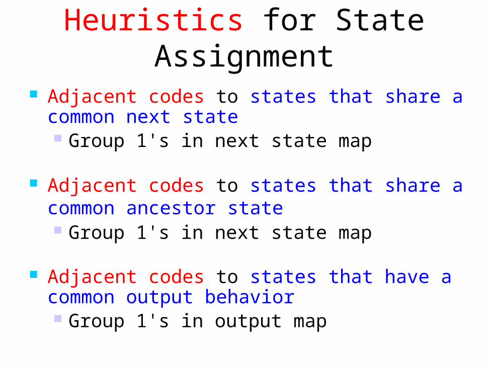
Heuristics for State Assignment
Adjacent codes to states that share a common next state Group 1's in next state map
Adjacent codes to states that share a common ancestor state Group 1's in next state map
Adjacent codes to states that have a common output behavior Group 1's in output map
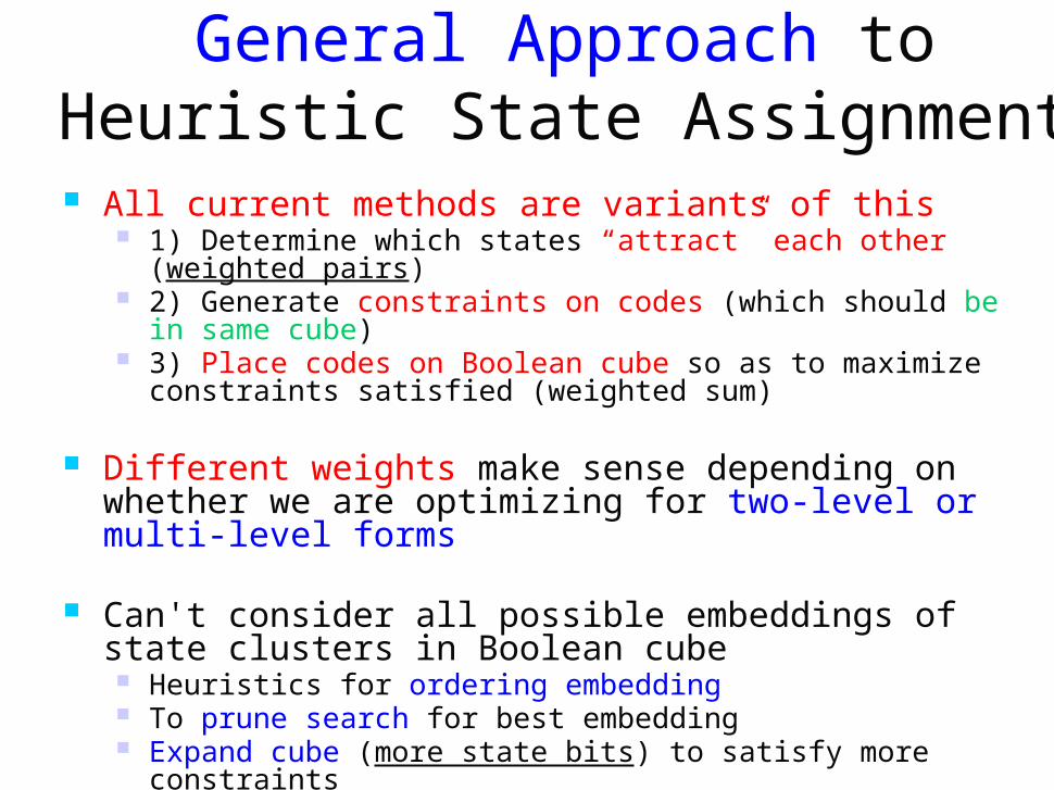
General Approach to Heuristic State Assignment
All current methods are variants of this 1) Determine which states “attract” each other (weighted
pairs) 2) Generate constraints on codes (which should be in same
cube) 3) Place codes on Boolean cube so as to maximize
constraints satisfied (weighted sum)
Different weights make sense depending on whether we are optimizing for two-level or multi-level forms
Can't consider all possible embeddings of state clusters in Boolean cube Heuristics for ordering embedding To prune search for best embedding Expand cube (more state bits) to satisfy more constraints
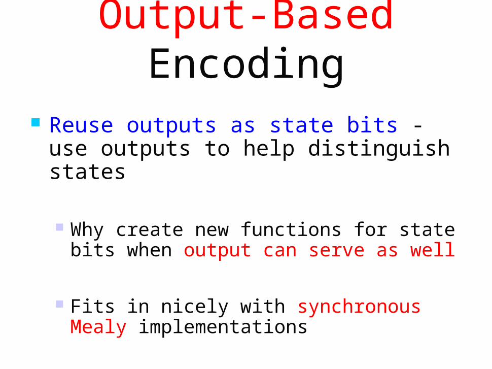
Output-Based Encoding
Reuse outputs as state bits - use outputs to help distinguish states
Why create new functions for state bits when output can serve as well
Fits in nicely with synchronous Mealy implementations

HG = ST’ H1’ H0’ F1 F0’ + ST H1 H0’ F1’ F0HY = ST H1’ H0’ F1 F0’ + ST’ H1’ H0 F1 F0’ FG = ST H1’ H0 F1 F0’ + ST’ H1 H0’ F1’ F0’ HY = ST H1 H0’ F1’ F0’ + ST’ H1 H0’ F1’ F0
Output patterns are unique to states, we do notneed ANY state bits – implement 5 functions(one for each output) instead of 7 (outputs plus2 state bits)
Inputs Present State Next State OutputsC TL TS ST H F0 – – HG HG 0 00 10 – 0 – HG HG 0 00 10 1 1 – HG HY 1 00 10 – – 0 HY HY 0 01 10 – – 1 HY FG 1 01 101 0 – FG FG 0 10 000 – – FG FY 1 10 00– 1 – FG FY 1 10 00– – 0 FY FY 0 10 01– – 1 FY HG 1 10 01
Example of KISS Format
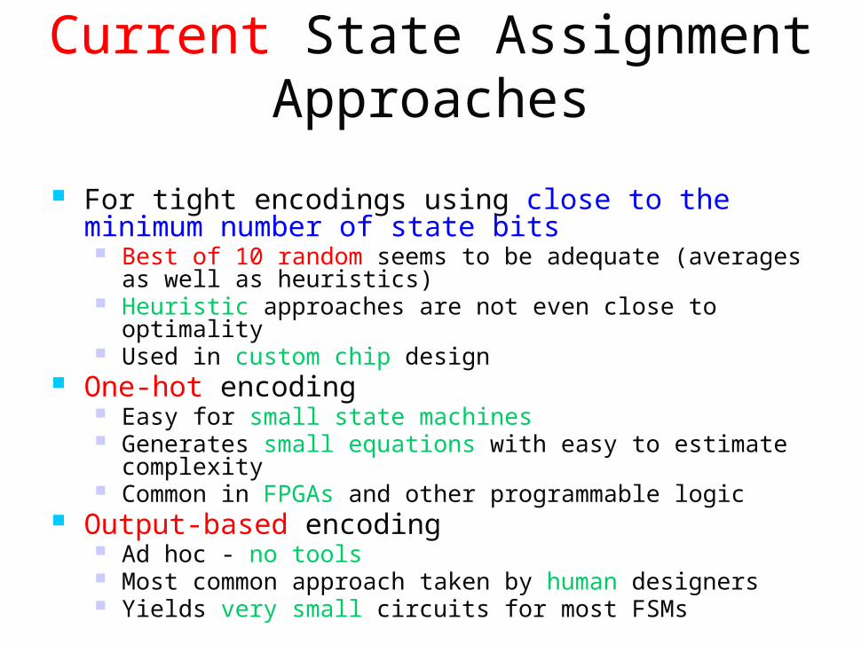
Current State Assignment Approaches
For tight encodings using close to the minimum number of state bits Best of 10 random seems to be adequate (averages as
well as heuristics) Heuristic approaches are not even close to optimality Used in custom chip design
One-hot encoding Easy for small state machines Generates small equations with easy to estimate
complexity Common in FPGAs and other programmable logic
Output-based encoding Ad hoc - no tools Most common approach taken by human designers Yields very small circuits for most FSMs

State Assignment = Various Methods
Assign unique code to each state to produce logic-level description utilize unassigned codes effectively as don’t cares
Choice for S state machine minimum-bit encoding
log S maximum-bit encoding
one-hot encoding using one bit per state
something in between Modern techniques
hypercube embedding of face constraint derived for collections of states (Kiss,Nova)
adjacency embedding guided by weights derived between state pairs (Mustang)

Hypercube Embedding Technique Observation : one -hot encoding is the easiest to decode Am I in state 2,5,12 or 17? binary : x4’x3’x2’x1x0’(00010) +
x4’x3’x2x1’x0 (00101) +
x4’x3x2x1’x0’(01100) +
x4x3’x2’x1’x0 (10001)
one hot : x2+x5+x12+x17
But one hot uses too many flip flops. Exploit this observation 1. two-level minimization after one hot encoding identifies useful state group for decoding 2. assigning the states in each group to a single face of the hypercube allows a single product term to decode the group to states.
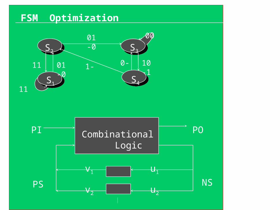
FSM Optimization
S2
S1
S3
01-0
00
10-1
0-1-01-0
11
11
Combinational Logic
PI PO
PS NS
u1
u2
v1
v2
S4
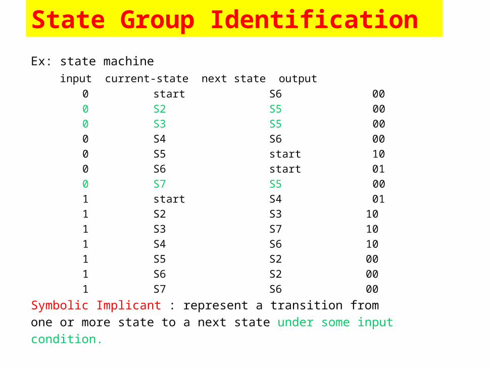
State Group Identification
Ex: state machine input current-state next state output 0 start S6 00 0 S2 S5 00 0 S3 S5 00 0 S4 S6 00 0 S5 start 10 0 S6 start 01 0 S7 S5 00 1 start S4 01 1 S2 S3 10 1 S3 S7 10 1 S4 S6 10 1 S5 S2 00 1 S6 S2 00 1 S7 S6 00
Symbolic Implicant : represent a transition from one or more state to a next state under some input condition.
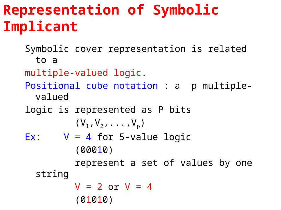
Representation of Symbolic Implicant
Symbolic cover representation is related to a multiple-valued logic.Positional cube notation : a p multiple-valued logic is represented as P bits (V1,V2,...,Vp)
Ex: V = 4 for 5-value logic (00010) represent a set of values by one string V = 2 or V = 4 (01010)
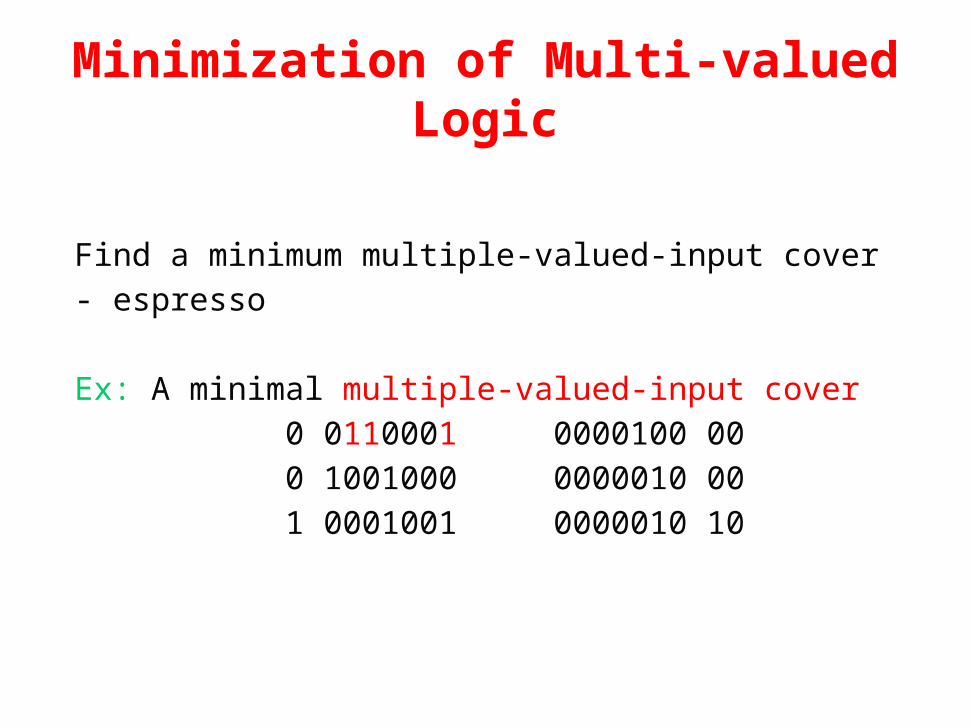
Minimization of Multi-valued Logic
Find a minimum multiple-valued-input cover - espresso
Ex: A minimal multiple-valued-input cover 0 0110001 0000100 00 0 1001000 0000010 00 1 0001001 0000010 10
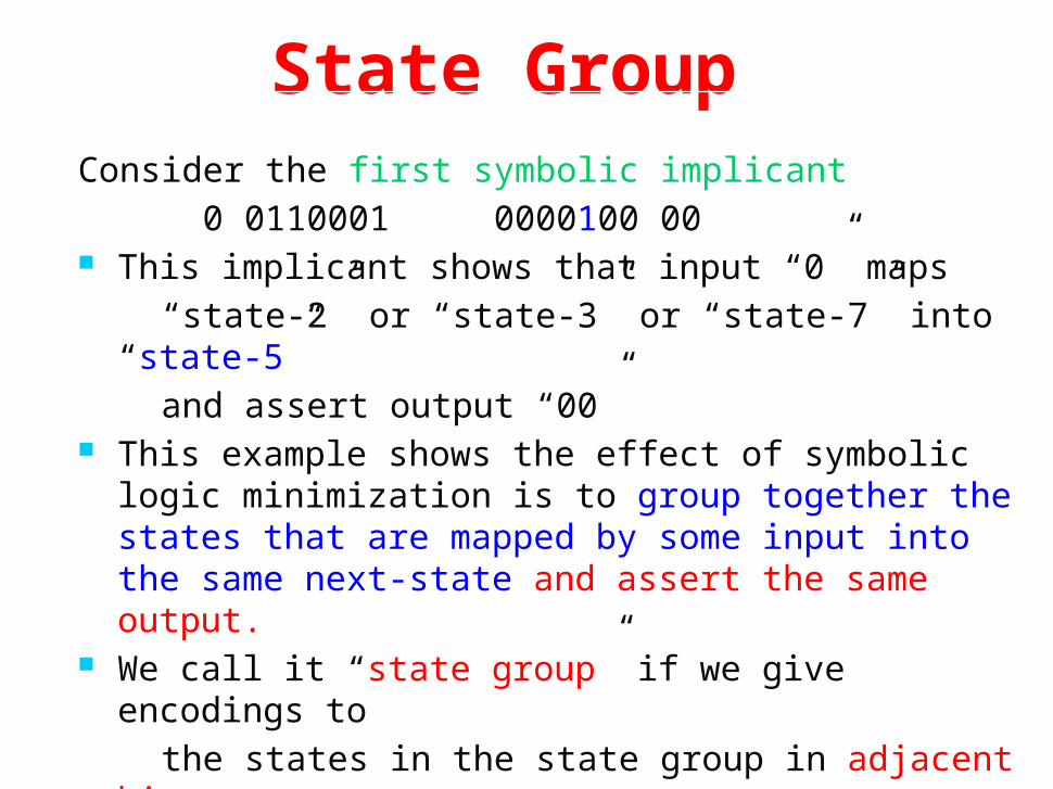
State GroupConsider the first symbolic implicant 0 0110001 0000100 00 This implicant shows that input “0” maps “state-2” or “state-3” or “state-7” into “state-5” and assert output “00” This example shows the effect of symbolic logic
minimization is to group together the states that are mapped by some input into the same next-state and assert the same output.
We call it “state group” if we give encodings to the states in the state group in adjacent binary logic and no other states in the group face, then the
states group can be implemented as a cube.
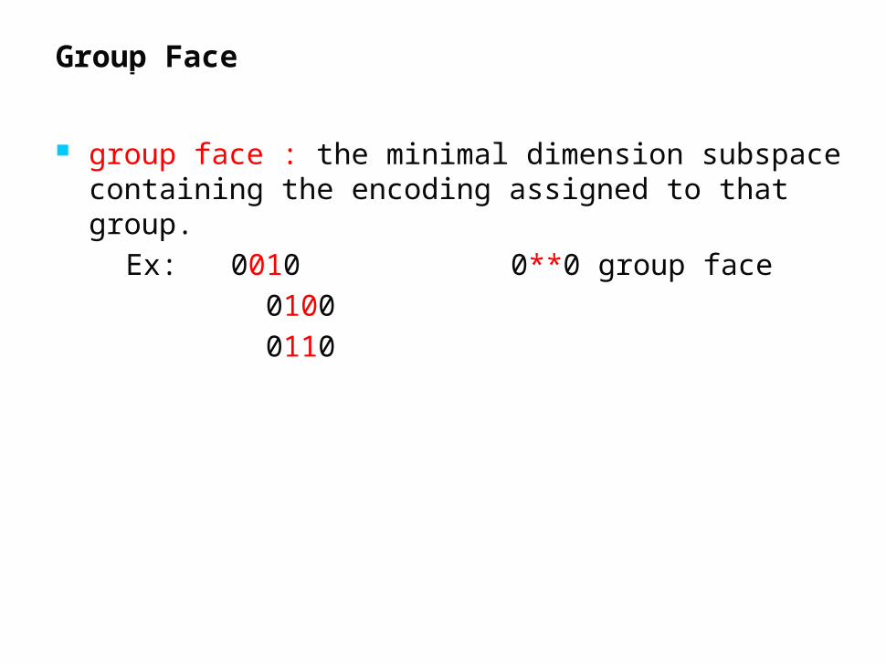
Group Face
group face : the minimal dimension subspace containing the encoding assigned to that group.
Ex: 0010 0**0 group face 0100 0110

Hyper-cube Embeddingc
a b
256
12 17
1256
2 17
state groups :{2,5,12,17}{2,6,17}
wrong!
Hyper-cube Embedding
c
a b
45
2
5
2 4
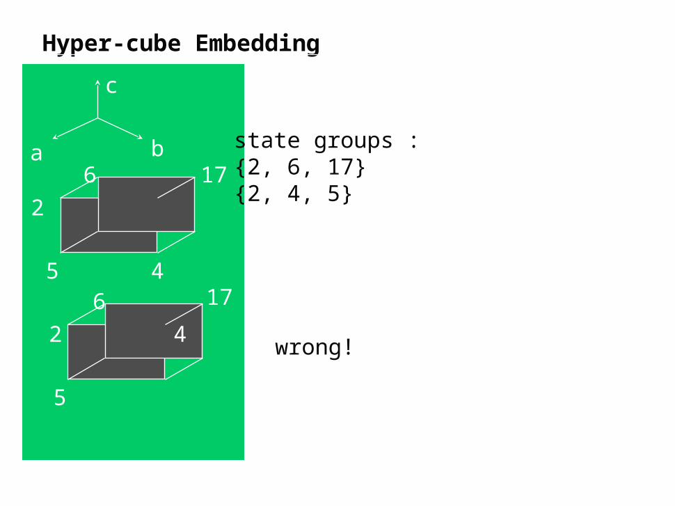
state groups :{2, 6, 17}{2, 4, 5}
wrong!
6 17
6 17
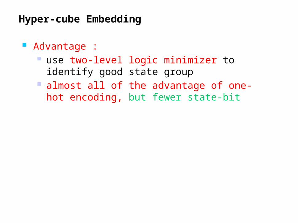
Hyper-cube Embedding
Advantage : use two-level logic minimizer to identify
good state group almost all of the advantage of one-hot
encoding, but fewer state-bit
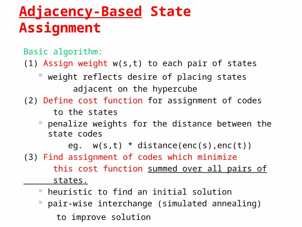
Adjacency-Based State Assignment
Basic algorithm:(1) Assign weight w(s,t) to each pair of states
weight reflects desire of placing states adjacent on the hypercube(2) Define cost function for assignment of codes to the states
penalize weights for the distance between the state codes eg. w(s,t) * distance(enc(s),enc(t))(3) Find assignment of codes which minimize this cost function summed over all pairs of states.
heuristic to find an initial solution pair-wise interchange (simulated annealing)
to improve solution

Adjacency-Based State Assignment
Mustang : weight assignment technique based on loosely maximizing common cube factors

How to Assign Weight to State Pair
Assign weights to state pairs based on ability to extract a common-cube factor if these two states are adjacent on the hyper-cube.
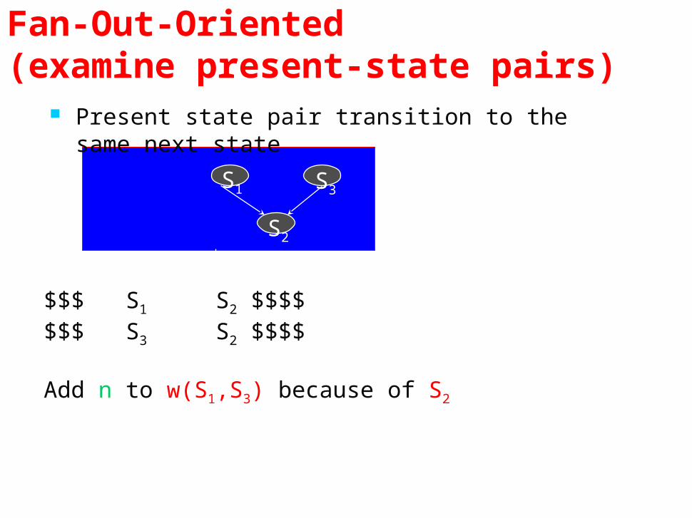
Fan-Out-Oriented (examine present-state pairs)
Present state pair transition to the same next state
S1 S3
S2
$$$ S1 S2 $$$$$$$ S3 S2 $$$$
Add n to w(S1,S3) because of S2

Fan-Out-Oriented
present states pair asserts the same output
S2
S3S1
S4
$/j $/j
Add 1 to w(S1 , S3) because of output j
$$$ S1 S2 $$$1$$$$ S3 S4 $$$1$

Fanin-Oriented (exam next state pair)
The same present state causes transition to next state pair.
$$$ S1 S2 $$$$
$$$ S1 S4 $$$$
Add n/2 to w(S2,S4) because of S1
S1
S2 S4

Fanin-Oriented (exam next state pair) The same input causes transition to next state
pair.
$0$ S1 S2 $$$$
$0$ S3 S4 $$$$
Add 1 to w(S2,S4) because of input i
i i
S1 S3
S2 S4
Which Method Is Better?
Which is better?
• FSMs have no useful two-levelface constraints => adjacency-embedding
• FSMs have many two-levelface constraints => face-embedding

Summary Models for representing sequential circuits
Abstraction of sequential elements Finite state machines and their state diagrams Inputs/outputs Mealy, Moore, and synchronous Mealy machines
Finite state machine design procedure Deriving state diagram Deriving state transition table Determining next state and output functions Implementing combinational logic
Implementation of sequential logic State minimization State assignment Support in programmable logic devices
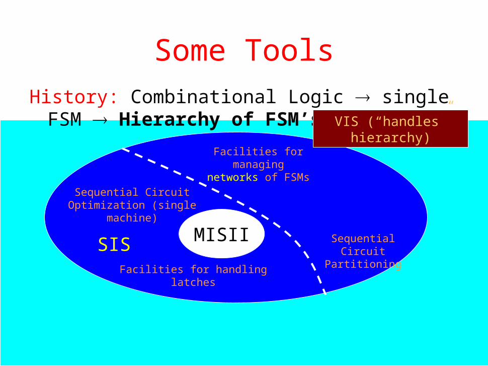
Some ToolsHistory: Combinational Logic single FSM
Hierarchy of FSM’s
MISII Sequential Circuit
Partitioning
Facilities for managing networks
of FSMs
VIS (“handles” hierarchy)
Sequential Circuit Optimization (single
machine)
SISFacilities for handling
latches