Embed Size (px)
Citation preview

INSTALLATION, OPERATION AND MAINTENANCE INSTRUCTIONS
SonicControl layer thickness measuring device for oil and coalescence separators
Ultrasonic sensor for precision measurement accurate to centimetres
Monitoring of oil thickness, sludge thickness and blockage
Protective rating ultrasonic probe IP 68
Alarm warning during power outage (Battery back-up)
Installable in all KESSEL oil and coalescence separators
Easy installation (inc. installation set)
Product Advantages
Name/Sign Date Company stamp
Installationthis unit was installed by the following licensed company
Commissioning Hand-Over
Edition: 2011/11ID-number: 395-120ENSubject to technical amendments
Abbildung zeigt Art.Nr. 917824
2
1. Safety Instructions ............ ............................................................................................. Page 4
2. General ............ ............................................................................................. Page 52.1 .......System types ..................................................................... Page 6
3. Installation and Assembly 3.1 Installation of the switch unit ............................................... Page 73.2 Installation of sensor and sensor bracket............................. Page 83.3 Installation dimensions of sensor ......................................... Page 113.4 Installation example ............................................................ Page 12
4. Electrical connection 4.1 External signal generator .................................................... Page 144.2 Shortening the sensor cable ............................................... Page 144.3 Extending the sensor cable.................................................. Page 144.4 Installation / cable connection.............................................. Page 154.5 Installation in explosion risk areas ....................................... Page 17
5. Operation 5.1 .......Prepared for operation ......................................................... Page 185.2 Duties of the user ................................................................. Page 185.3 Instruction / Handover.......................................................... Page 18
6. Inspection and Maintenance .......................................................................................................... Page 19
7. Errors and Malfunction 7.1 ......Incident display ................................................................... Page 207.2 ......Fault display......................................................................... Page 217.3 ......General faults....................................................................... Page 23
8. Switch unit 8.1 ......Menu navigation................................................................... Page 248.2 ......System menu ....................................................................... Page 248.3 ......Information menu ................................................................. Page 258.3.1 ...Operating hours .................................................................. Page 258.3.2 ...Log book ............................................................................. Page 258.3.3 ...Control unit type................................................................... Page 25
Table of contents

3
8.3.4 ....Servicing date ..................................................................... Page 258.3.5 ...Current measured values..................................................... Page 258.3.6 ...Parameters .......................................................................... Page 258.3.7 ....Measured data memory ...................................................... Page 258.3.8 ...Disposal .............................................................................. Page 258.4 ......Servicing menu ................................................................... Page 268.4.1 ....Manual mode ...................................................................... Page 268.4.2 ...Servicing dates ................................................................... Page 268.5 ......Settings menu ...................................................................... Page 278.5.1 ...Parameters .......................................................................... Page 278.5.2 ....Profile memory. .................................................................... Page 278.5.3 ...Date/time.............................................................................. Page 278.5.4 ....Nominal size ........................................................................ Page 278.5.5 ....Communication .................................................................... Page 278.5.6 ...Language............................................................................. Page 278.5.7 ...Expert mode......................................................................... Page 278.5.8 ....Reset.................................................................................... Page 278.5.9 ...SonicControl model.............................................................. Page 27
9. Technical data 9.1 .......Technical Data for Control Unit ............................................ Page 289.2 .......Technical Data for Ultrasonic Sensor ................................... Page 29
10. Replacement Parts and Assessories .......................................................................................................... Page 30
11. Connection Plan .......................................................................................................... Page 31
12. Declaration of Conformity .......................................................................................................... Page 32
13. Warranty .......................................................................................................... Page 33
14. Handover Ceritficate .......................................................................................................... Page 34
Table of contents
4
1. Safety Instructions
Dear customer,
Before you put your KESSEL SonicCon-trol into operation, please read throughthe installation instructions carefully andfollow them.
Check first whether the system has arrivedundamaged. In case of any transport dama-ge, please refer to the instructions in chap-ter 12 "Warranty".
1. Safety instructions:During installation, operation, maintenanceor repair of the system, the regulations forthe prevention of accidents, the pertinentDIN and VDE standards and directives, aswell as the directives of the local power sup-ply industry must be heeded.
Installation, Operation and Service of theSonicControl may only handled by a profes-sional licensed service company. The So-nicControl may not be repaired , changed ormanipulated. In the case of a product defect,
the entire SonicControl system should bereplaced
Before putting the device into operation,make sure through professional examinati-on that the necessary protective features areavailable. Grounding, neutral, residual cur-rent-operated protective circuit etc. mustcorrespond to the requirements of the localpower supply industry.
The system operates on electrical current.Noncompliance with the operating instruc-tions may result in considerable damage toproperty, personal injuries or even fatal ac-cidents.
The system must be disconnectedfrom the mains before any work iscarried out on it!
This system is appropriate for ex-plosion rated areas listed as Ex-Zone 0.
It must be ensured that the electric cables aswell as all other electrical system equipmentare in a faultless condition. In case of da-mage, the system may on no account be putinto operation or must be stopped immedia-tely.
The system must be inspected and servicedregularly to maintain its operational ability.We recommend that you conclude a servi-cing contract with your installation company.We recommend that the system is checkedon a weekly basis for proper operation.
The installation of the ultrasonic sensor insi-de the separation tank may only take placewhen the separator contains no dangerouswastewater, gases or fumes.

5
Dear customer,
we are pleased that you have decided to buy a KESSEL product.The entire system was subjected to a stringent quality control before it left our factory. Nevertheless, please check immediately whetherthe system has been delivered to you complete and undamaged. In case of any transport damage, please refer to the instructions in thechapter “Warranty” in this manual.These installation, operating and maintenance instructions contain important information that has to be observed during assembly, ope-ration, maintenance and repair. Prior to carrying out any work on the system, the operator and the responsible technical personnel mustcarefully read and heed these installation and operating instructions.
2. General
SonicControl for oil and coalescence separators: The SonicControl measuring device for oil and coalescence separators monitors accurately (to the centimetre) the current layer thickn-ess of collected oil / fuel on the surface of the separator as well as sludge at the base of the separator and also warns when back-upsoccur into the separator.
Proper Operation:The UltraSonic sensor is a compact system for installation in EX-Zone 0 rated areas inside oil and coalescence separators. The systemis designed to monitor the following:O = oil / fuel layer thicknessS = sludge layer thicknessA = Back-up warning
SonicControl is an automatic operated warning system which according to DIN EN 858-1 is recommended for use with oil and coales-cence separators.
The following models are available: 1. OSA, 2. OS, 3. OA, 4. SA, 5. O, 6. S, 7. A
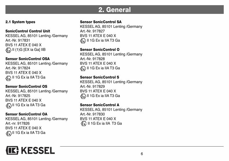
2.1 System types
SonicControl Control UnitKESSEL AG, 85101 Lenting /GermanyArt.-Nr. 917831BVS 11 ATEX E 040 X
II (1)G [EX ia Ga] IIB
Sensor SonicControl OSAKESSEL AG, 85101 Lenting /GermanyArt.-Nr. 917824BVS 11 ATEX E 040 X
II 1G Ex ia IIA T3 Ga
Sensor SonicControl OSKESSEL AG, 85101 Lenting /GermanyArt.-Nr. 917825BVS 11 ATEX E 040 X
II 1G Ex ia IIA T3 Ga
Sensor SonicControl OAKESSEL AG, 85101 Lenting /GermanyArt.-nr. 917826BVS 11 ATEX E 040 X
II 1G Ex ia IIA T3 Ga
Sensor SonicControl SAKESSEL AG, 85101 Lenting /GermanyArt.-Nr. 917827BVS 11 ATEX E 040 X
II 1G Ex ia IIA T3 Ga
Sensor SonicControl OKESSEL AG, 85101 Lenting /GermanyArt.-Nr. 917828BVS 11 ATEX E 040 X
II 1G Ex ia IIA T3 Ga
Sensor SonicControl SKESSEL AG, 85101 Lenting /GermanyArt.-Nr. 917829BVS 11 ATEX E 040 X
II 1G Ex ia IIA T3 Ga
Sensor SonicControl AKESSEL AG, 85101 Lenting /GermanyArt.-Nr. 917830BVS 11 ATEX E 040 X
II 1G Ex ia IIA T3 Ga
2. General
6

3. Installation and Assembly
3.1 Wall mounting of the control unit
The control unit must be installed in a dry andfrost free area – preferable indoors where anyalarms and control unit message can be seen /heard. Do not install the control unit in directsunlight!
Caution!!!! The control unit is not tobe installed inside the oil or coale-scence separator!!!
In order to mount the control unit the control unitcover does not need to be opened. Pre-drill 2 x6mm diameter holes 168mm apart (use the dril-ling template if required)
Installation:1. Drill two holes2. Insert two dowels3. Screw in two screws to proper depth4. Hang control unit on two screws5. Affix the control unit on the screws by pus-
hing the control unit down until it seat firmlyon both screws.
Illustration of SonicControl control unit
7
3. Installation and Assembly
Installation SonicControl
The SonicControl should be completely dis-connected form power before the system isinstalled or during any maintenance work.The system should only be connected topower after the control unit and the ultraso-nic sensor have connected. The ID stickeron the control unit should not be removed.
3.2 Installation of sensor and sensorbracket
The sensor is properly protected and may beinstalled in Zone 0 explosion rated areas ac-cording to 94/9/EG (ATEX).
The cable and the ID sticker are an integralpart of the product. The ID sticker must re-main on the cable if the cable is to be shor-tened. If a conduit is required to lay thecable, it is recommended that a conduit with50mm diameter is used.
The ultrasonic sensor is IP 68 protected andis weather and oil / fuel resistant – due to thisis can be installed in oil and coalescence se-parators.
The ultrasonic sensor is designed for use intemperatures from -10 deg C to + 50 deg C(263K to 323K)
Sensors certified for use in explosi-on risk areas
In oil and coalescence separators, sensorscan only be installed that are certified for usein explosion risk areas.
The ultrasonic installation bracket must beinstalled with the supplied screws inside theupper section of the fuel separator – thisarea is above fluid level meaning the instal-lation screws holes will not cause any leaksto the watertight system.
Caution!!!! If the ultrasonic sensor is beinginstalled in a fuel or coalescence separatorthat is already in use, no electric or batterypowers tools such as drills may be used du-ring installation. Only use normal hand helpscrew drivers.
If back-up (flooding) has occurredwithin the separator, the ultrasonicsensor should be inspected after-wards that it is still in the proper lo-cation and then it is clear of debris.
8
Please note the safety instructions!

9
3. Installation and Assembly
Article Number of oil or coalescence separator Sludge Oil / Fuel
1) % full Measured layer Disposal 2) % full Measured layer Disposal
thickness volume thickness volume
in mm in liters in mm in liters
99403.10B 99403.10BEX 99503.10B 99503.10BEX 50 650 1000 100 131 187
99403.10D 99403.10DEX 99503.10D 99503.10DEX 40 530 800 80 105 150
30 430 600 60 79 112 1050
20 330 400 40 52 75
10 210 200 20 26 37
99610.15B 99610.15BEX 99710.15B 99710.15BEX 50 650 1500 100 131 262
99610.15D 99610.15DEX 99710.15D 99710.15DEX 40 550 1200 80 105 210
30 450 900 60 79 157 1050
20 340 600 40 52 105
10 220 300 20 26 52
99606.30B 99606.30BEX 99706.30B 99706.30BEX 50 1100 3000 100 138 265
99606.30D 99606.30DEX 99706.30D 99706.30DEX 40 930 2400 80 110 212
99610.30B 99610.30BEX 99710.30B 99710.30BEX 30 760 1800 60 83 159 1550
99610.30D 99610.30DEX 99710.30D 99710.30DEX 20 580 1200 40 55 106
10 370 600 20 28 53
99606.80B 99606.80BEX 99706.80B 99706.80BEX 50 1100 4000 100 138 380
99606.80D 99606.80DEX 99706.80D 99706.80DEX 40 910 3200 80 110 304
99610.80B 99610.80BEX 99710.80B 99710.80BEX 30 740 2400 60 83 228 1550
99610.80D 99610.80DEX 99710.80D 99710.80DEX 20 560 1600 40 55 152
99615.80B 99615.80BEX 99715.80B 99715.80BEX 10 350 800 20 28 76
99615.80D 99615.80DEX 99715.80D 99715.80DEX
1)The separator contents should be emptied when the sludge layer is 50% full
2)The separator contents should be emptied when the oil / fuel layer is 80% full – not disposing at this stage would exceed the oil / fuel storage capacity of the separator
Distance greens markto Container
ground

10
Article Number of oil or coalescence separator Sludge Oil / Fuel
1) % full Measured layer Disposal 2) % full Measured layer Disposal
thickness volume thickness volume
in mm in liters in mm in liters
99703.04B 50 400 550 100 235 200
99703.04D 40 320 369 80 188 160
30 240 305 60 141 120 980
20 160 241 40 94 80
10 80 177 20 47 40
99703.10B 50 800 1050 100 235 200
99703.10D 40 640 815 80 188 160
30 480 587 60 141 120 1480
20 320 369 40 94 80
10 160 241 20 47 40
99706.10B 50 400 550 100 235 200
99706.10D 40 320 369 80 188 160
30 240 305 60 141 120 940
20 160 241 40 94 80
10 80 177 20 47 40
1)The separator contents should be emptied when the sludge layer is 50% full
2)The separator contents should be emptied when the oil / fuel layer is 80% full – not disposing at this stage would exceed the oil / fuel storage capacity of the separator
Adjustment of the SonicControl sensor can be handled with two different methods:1) By measuring with a ruler (separator must be empty in order to use this method)2) The sensor is adjusted using the colored marks. The separator must be filled with clean water in order to use this method
(must not be filled with oil or fuel).
3. Installation and Assembly
Distance greens markto Container
ground

11
3. Installation and Assembly
3.3 Installation of sensor holding bracket.
A
1. Open the cover on the oil or coalescence sepa-rator (use caution removing the heavy cast ironor concrete covers – a lifting aid system is re-commended.
2. Using the including drilling template bracket,mark on the upper section of the separator thetwo holes located on the bracket. Drill two 6mmholes in the location of the two marks.
3. Screw the two included screws into the twoholes in the upper section until there is a di-stance of 25mm between screw head andupper section wall.
4. In the case that the separator has installed dee-per than the standard installation depths, usethe supplied pipe (D) as an extension.
5. Now clip the SonicControl sensor in the holdingclips (C) and then secure the bracket (B) byhanding it onto the two screws. Now fully tigh-ten the two screws so that the bracket is secu-rely fixed to the separator’s upper section
6. Now adjust the SonicControl sensor to thegreen mark on the sensor with the full waterlevel (for information on the sensor green mark,please see the next page.
C
B D
Caution – the Sonic-Control’s cable shouldnot be in the way orabove any of the sen-sor probes

12
3. Installation and Assembly3.4 Installation Example
The sensor should be in-stalled so that the sensorfingers point toward thecenter of the tank, this willprotect the sensors fromany debris that may fallinto the separator.
The sensor should be in-stalled so that the base ofthe pointed green arrow isat the exact height of theseparator's water level du-ring calm / clean conditions(no fuel or oil in separator)
Distance between baseof pointed green arrowand chamber bottom (for dimensions seetable S.9

13
3. Installation and Assembly
Ill. shows an underground fuel separator size NS 7 to NS 20
During the installation of the underground fuel separator, a DN 40 (OD 50mm) conduit pipe shouldbe laid two the separator dome that will contain the SonicControl sensor. In the dome area of theseparator tank (as seen in the above ill.) a 60mm hole should be drilled out of the tank using ahole saw. The control unit and the separator should be located as close to each other as possi-ble. The conduit pipe should be laid with no bends over 45 degree (maximum fitting bend shouldbe 45 degrees). The conduit pipe should be installed with a constant slope toward the separatorso that any condense water will flow back into the separator and not toward the control unit orpond in the conduit pipe. In the case that the conduit may need to be extended at a later date orthe sensor cable needs to be replaced, a string can by laid in the conduit pipe to aid running newcables. The SonicControl cable may be extended to a total length of 60 meters. The cable screwmust be tightly fastened before running the SonicControl cable back toward the control unit. Fi-nally secure tightly the black plastic conduit pipe cover. If a back up occurs inside the separa-tor the SonicControl sensor must be inspected and cleaned if necessary.
inside outside
Order-Nr. 917822
Ill. shows an underground fuel separator size NS 1 to NS 4
14
4. Electrical Connections
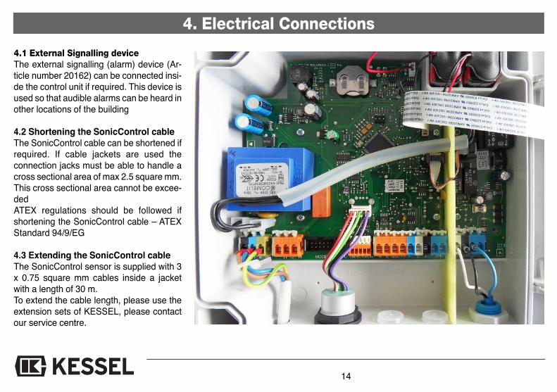
4.1 External Signalling deviceThe external signalling (alarm) device (Ar-ticle number 20162) can be connected insi-de the control unit if required. This device isused so that audible alarms can be heard inother locations of the building
4.2 Shortening the SonicControl cableThe SonicControl cable can be shortened ifrequired. If cable jackets are used theconnection jacks must be able to handle across sectional area of max 2.5 square mm.This cross sectional area cannot be excee-dedATEX regulations should be followed ifshortening the SonicControl cable – ATEXStandard 94/9/EG
4.3 Extending the SonicControl cableThe SonicControl sensor is supplied with 3x 0.75 square mm cables inside a jacketwith a length of 30 m. To extend the cable length, please use theextension sets of KESSEL, please contactour service centre.
15
4. Electrical Connections
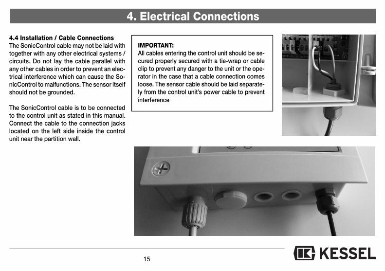
4.4 Installation / Cable ConnectionsThe SonicControl cable may not be laid withtogether with any other electrical systems /circuits. Do not lay the cable parallel withany other cables in order to prevent an elec-trical interference which can cause the So-nicControl to malfunctions. The sensor itselfshould not be grounded.
The SonicControl cable is to be connectedto the control unit as stated in this manual.Connect the cable to the connection jackslocated on the left side inside the controlunit near the partition wall.
IMPORTANT:All cables entering the control unit should be se-cured properly secured with a tie-wrap or cableclip to prevent any danger to the unit or the ope-rator in the case that a cable connection comesloose. The sensor cable should be laid separate-ly from the control unit’s power cable to preventinterference
16
4. Electrical Connections
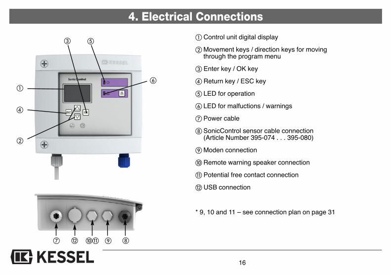
� Control unit digital display
� Movement keys / direction keys for movingthrough the program menu
� Enter key / OK key
� Return key / ESC key
� LED for operation
� LED for malfuctions / warnings
� Power cable
SonicControl sensor cable connection(Article Number 395-074 . . . 395-080)
Moden connection
� Remote warning speaker connection
� Potential free contact connection
USB connection
* 9, 10 and 11 – see connection plan on page 31
�
�
�
�
�
�
�� �

17
4. Electrical Connections
4.5 Installation of electrical equipment inexplosion risk areas
The self protected electrical systems of theSonicControl, which are identified by their bluecolor, are certified for installation in explosionrisk areas and to be used with the Ex i-connec-tions of the SonicControl ATEX.
The electrical installation in explosion riskareas must follow EN 60079-0 and EN 60079-14 regulations.
Installations in Germany must also follow EIN60079-14VDE 0165 Part 1 regulations.
When connecting the intrinsically secured cir-cuit of the associated equipment - installationin a secure area- (SonicControl ATEX controlunit) and when connecting of the intrinsicallysecured equipment - installation in explosionrated area - (SonicControl ATEX sensor), besure that all related max values (U; I; P) are fol-lowed and met.
Sine the connection of both explosion protec-ted systems have been certified with the EGtype examination certificate BVS 11 ATEX E040 X, no individual verification is required ac-cording to RL 94/9/EG and ATEX 95.
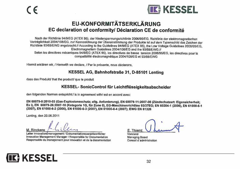
Related Norms and Regulations
EN 60079-0:2010-03 (Explosion risk areas /atmospheres)EN 60079-11:2007-08 (Protection classes,self safety; Ex i)EN 60079-26:2007-10 (Operating materialwith system protection level (EPL Ga)EN 60079-14:2009-05 (Explosion risk areas /connection of electronic systems)
EN 61000-6-1 (2007 (interference resistance)EN 61000-6-3 (2007) (emitted interference)Regulation RL94/9/EG (ATEX 95)Low current regulations 2006/95/EG

18
5. Operation
5.1 Getting the system ready for opera-tion
Plug the mains plug of the control unit intothe socket. The system will initialise auto-matically.During initial initialisation of the system, thecontrol unit requires that the user select fourbasic settings.1. Language2. Date/time3. Type of system*4. Typ of coalesence separator*
➤ Selection using ▲ ▼
➤ Stored in system memory by pressing“OK”
➤ After setting 1 to 4➤ Switch unit loads program memory➤ Start operating mode➤ System is ready for operation
5.2 Operator's dutiesChecks- for transport or installation damage- for structural defects of all electrical andmechanical components for seat and fun-ction
- the cable connections
Customer instruction based on the in-stallation and operating instructions
- Go through installation and operating in-structions with the customer
- System operation (explaining and descri-bing)
- Explanation to the customer about theoperator’s duties
- Remind about regular servicing (see chap-ter 6)
5.3 Instruction / Handover
The chapter "Safety instructions" mustbe heeded (page 4)!
Commissioning is carried out by a speciali-sed firm or by an authorised KESSEL agent(at an additional charge). The following per-sons should be present for the handover:- Person authorised to perform the accep-
tance on behalf of the building owner- Specialised firmIn addition, we recommend the participationof operating personnel/operator and thewaste disposal contractor.Summary of instructions:- Get the system ready for operation- Check the system- Instruction based on the installation and
operating instructions- Preparation of the handover certificate
(see chapter 13)➤ Once instruction is completed, the sy-
stem must be made ready for operation.
19
6. Inspection and Maintenance
Please heed the safety instructions in chapter 1.
All power should be disconnected from the system when any main-tenance or service work is being performed. If the two 9-volt batte-ries in the control unit are to be replaced, use only 450 mAh types.Repairs to this system should only be handed by the manufacturer.
The control unit itself requires no maintenance.Cable connections should be checked for damage.The SonicControl sensor needs to be cleaned on a regular basis.
Every time the oil / coalescence separator is emptied / disposed, thesensor must be cleaned withwarm/hot water*. When a high-pressure jet cleaner is used, main-tain a safe distance of 30 cm.The sensor does not have to be removed for cleaning.
The SonicControl control unit and the sensor are connected by acable with a maximum total length of 30 meters. Only this cableshould be used, no other cable is allowed for connection. If thiscable needs to be cleaned, used only a moist towel to prevent anybuild up of static electricity.
The sensor may not be used with corrosive fluids.
The sensor is maintenance free. In order to assure proper operati-on of the entire system, the sensor function should be checked onceper year.
RepairsThe SonicControl system may not be repaired, changed or mani-pulated. In case the SonicControl is damaged or defective it mustbe replaced by a new system.
DisposalIn the case that the SonicControl is damaged or no longer requiredand needs to be disposed of, please follow all local and national dis-posal regulations in your area.
The SonicControl control unit contains two 9-volt batteries whichshould be disposed of properly.
Please follow this all the safety instructions in this operating manualwhen operating this system.
20
7. Errors and Malfunction Please heed the safety instructions in chapter 1.
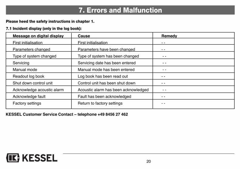
7.1 Incident display (only in the log book):
Message on digital display Cause Remedy
First initialisation First initialisation - -
Parameters changed Parameters have been changed - -
Type of system changed Type of system has been changed - -
Servicing Servicing date has been entered - -
Manual mode Manual mode has been entered - -
Readout log book Log book has been read out - -
Shut down control unit Control unit has been shut down - -
Acknowledge acoustic alarm Acoustic alarm has been acknowledged - -
Acknowledge fault Fault has been acknowledged - -
Factory settings Return to factory settings - -
KESSEL Customer Service Contact – telephone +49 8456 27 462

21
7. Errors and Malfunction
Message on digital display Type of warning Cause Remedy
PRE-ALARM layer thickness Blinking (alarm) Oil / Fuel layer has Monitor oil / fuel reached pre-alarm layer and dispose thickness when required
No rest phase detected Blinking (alarm) Measurement took place Check measurement in during operation (waste- Parameter section of control water entering separator) unit and re-set if required– inaccurate results
ALARM layer thickness Acoustical alarm and Maximum oil / fuel Dispose separator contentsflashing LED layer thickness reached
Power outage Acoustical alarm System is no longer Check fusing, F1 switch and flashing LED received power and mains power supply
7.2 Errors and Malfunctions
22
7. Errors and Malfunction
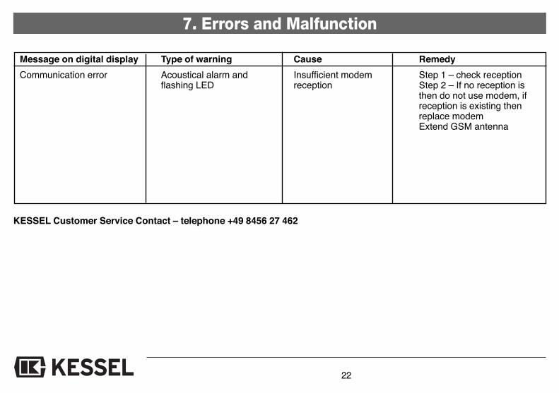
Message on digital display Type of warning Cause Remedy
Communication error Acoustical alarm and Insufficient modem Step 1 – check receptionflashing LED reception Step 2 – If no reception is
then do not use modem, if reception is existing then replace modemExtend GSM antenna
KESSEL Customer Service Contact – telephone +49 8456 27 462

23
7. Errors and Malfunction
7.3 General Errors
Known error Type of warning Cause Remedy
Difference between displayedoil / fuel layer thickness andmanually measured thickness
Error due to improper SonicControl measurement
- SonicControl sensor improperly connected
- SonicControl position incorrect
- Improper initialization- Debris on sensor- Separator size / Article
number improperly entered
- Check all cable connections(please follow section 3.4 – In-stallation)
- Check to make sure type and size of separator has been correctly entered
- Service the oil / fuel separator- Empty / dispose of separator
and clean SonicControl sensor- Check sensor position and re-
position if necessary (see p. 11)- Check settings and correct if ne-
cessary
SMS use or remote mainten-ance not possible
Remote maintenance error Insufficient modem reception Step 1 – check modem receptionStep 2 - If no reception is availa-ble then do not use modem,if reception is existing then replace modemExtend GSM antenna

24
8. Control Unit
8.1 Menu guidanceThe control unit's menu navigation is sub-divided into the systeminformation as wellas three different main menu items. Thebackground lighting is activated if one ofthe control keys is pressed once.
OK Button: Skips to the next higherlevel
ESC Button: Skip to the next lower level
▲ Navigation within a level ▼
Alarm Button The acoustic signal can beacknowledged by pressingthis key once. If the faulthas been eliminated, thevisual fault can also beacknowledged by pressingthe alarm key again for 3seconds or more.
If the fault has not been eliminated, theacoustic alarm is triggered again whenthe alarm key is pressed again.
In case of a mains power failure, the sy-stem is not ready for operation. The con-trol unit switches to stand-by mode (bat-tery operation) which will last for at least72 hours if the batteries are completelyfull. This becomes noticeable by means ofan acoustic and visual alarm. The acou-stic alarm can be acknowledged by pres-sing the alarm key. By pressing the Alarmbutton for 5 seconds or more, the poweroutage warning mode can be achknow-ledged and the control unit will be auto-matically turned off – this can serve tosave battery power. If the mains connec-tion is re-established, the program will au-tomatically continue with the last programphase.
Note:Certain menus are password-protected.This serves to protect the system againstinappropriate use.If you have any questions, please contactKESSEL Customer Services (Phone +49(0) 8456 / 27462)
8.2 System-Menü
System info Informations
Maintenance
Settings
25
8. Control Unit8.3 Information menu
System info Informations
Maintenance
Settings
Operating hours
Log book
Control unit type
Servicing date
Current measuredvalues
Parameters
Measured data
Disposal
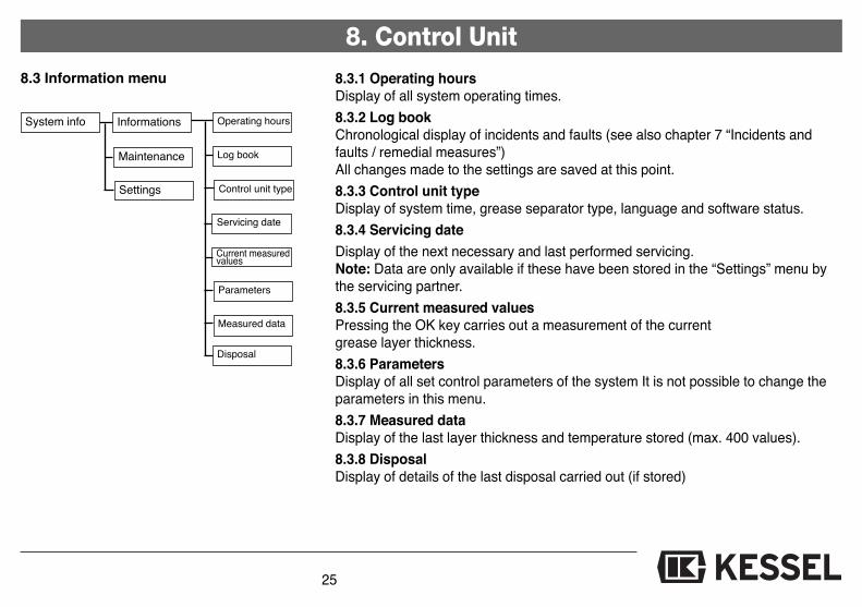
8.3.1 Operating hoursDisplay of all system operating times.
8.3.2 Log bookChronological display of incidents and faults (see also chapter 7 “Incidents andfaults / remedial measures”) All changes made to the settings are saved at this point.
8.3.3 Control unit typeDisplay of system time, grease separator type, language and software status.
8.3.4 Servicing date
Display of the next necessary and last performed servicing.Note: Data are only available if these have been stored in the “Settings” menu bythe servicing partner.
8.3.5 Current measured valuesPressing the OK key carries out a measurement of the current grease layer thickness.
8.3.6 ParametersDisplay of all set control parameters of the system It is not possible to change theparameters in this menu.
8.3.7 Measured data Display of the last layer thickness and temperature stored (max. 400 values).
8.3.8 DisposalDisplay of details of the last disposal carried out (if stored)
26
8.4 Maintenance menu
8. Control Unit
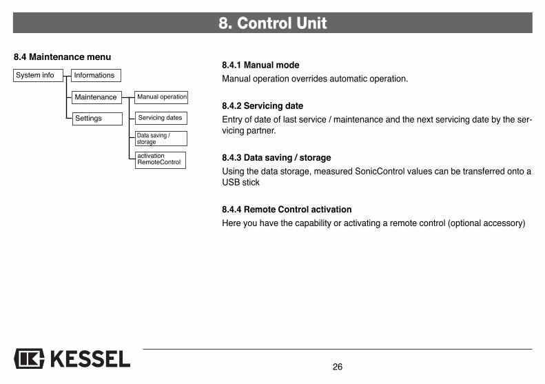
8.4.1 Manual mode
Manual operation overrides automatic operation.
8.4.2 Servicing date
Entry of date of last service / maintenance and the next servicing date by the ser-vicing partner.
8.4.3 Data saving / storage
Using the data storage, measured SonicControl values can be transferred onto aUSB stick
8.4.4 Remote Control activation
Here you have the capability or activating a remote control (optional accessory)
System info Informations
Maintenance
Settings
Manual operation
Servicing dates
Data saving /storage
activationRemoteControl
27
8. Control Unit
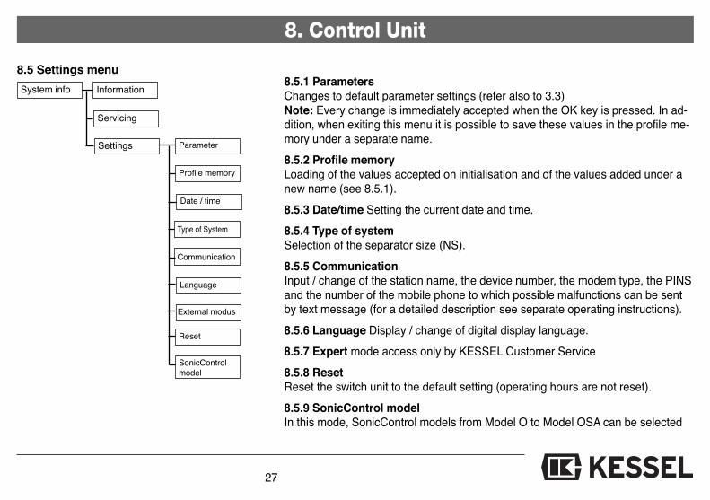
8.5.1 ParametersChanges to default parameter settings (refer also to 3.3)Note: Every change is immediately accepted when the OK key is pressed. In ad-dition, when exiting this menu it is possible to save these values in the profile me-mory under a separate name.
8.5.2 Profile memoryLoading of the values accepted on initialisation and of the values added under anew name (see 8.5.1).
8.5.3 Date/time Setting the current date and time.
8.5.4 Type of systemSelection of the separator size (NS).
8.5.5 CommunicationInput / change of the station name, the device number, the modem type, the PINSand the number of the mobile phone to which possible malfunctions can be sentby text message (for a detailed description see separate operating instructions).
8.5.6 Language Display / change of digital display language.
8.5.7 Expert mode access only by KESSEL Customer Service
8.5.8 Reset Reset the switch unit to the default setting (operating hours are not reset).
8.5.9 SonicControl model In this mode, SonicControl models from Model O to Model OSA can be selected
8.5 Settings menu
System info Information
Servicing
Settings Parameter
Profile memory
Date / time
Type of System
Communication
Language
External modus
Reset
SonicControlmodel
28
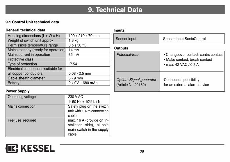
9. Technical Data
9.1 Control Unit technical data
General technical dataHousing dimensions (L x W x H) 190 x 210 x 70 mm
Weight of switch unit approx 1.3 kg
Permissible temperature range 0 bis 50 °C
Mains standby (ready for operation) 14 mA
Mains current in operation 35 mA
Protective class I
Type of protection IP 54
Electrical connections suitable for
all copper conductors 0,08 - 2,5 mm
Cable sheath diameter 5 - 9 mm
Battery 2 x 9V – 680 mAh
Power SupplyOperating voltage 230 V AC
1~50 Hz ± 10% L / NMains connection Safety plug on the switch
unit with 1.4 m connectioncable
Pre-fuse required max. 16 A (provide on in-stallation side), all-polemain switch in the supplycable
Inputs
Sensor input Sensor input SonicControl
Outputs
Potential-free • Changeover contact: centre contact,
• Make contact; break contact
• max. 42 VAC / 0.5 A
Option: Signal generator Connection possibility
(Article Nr. 20162) for an external alarm device
9. Technical Data
29
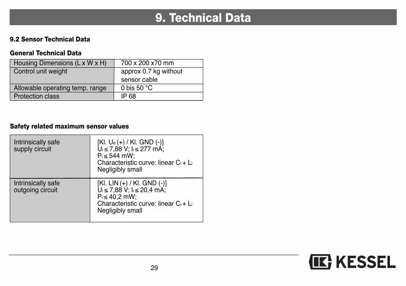
Intrinsically safe [Kl. Ue (+) / Kl. GND (-)]supply circuit Ui ≤ 7,88 V; li ≤ 277 mA;
Pi ≤ 544 mW; Characteristic curve: linear Ci + Li
Negligibly small
Intrinsically safe [Kl. LIN (+) / Kl. GND (-)]outgoing circuit Ui ≤ 7,88 V; li ≤ 20,4 mA;
Pi ≤ 40,2 mW; Characteristic curve: linear Ci + Li
Negligibly small
Safety related maximum sensor values
General Technical DataHousing Dimensions (L x W x H) 700 x 200 x70 mm
Control unit weight approx 0.7 kg without
sensor cable
Allowable operating temp. range 0 bis 50 °C
Protection class IP 68
9.2 Sensor Technical Data

30
10. Replacement Parts and Accessories
Article Order Nr11. Control unit 395-03712. Ultra sonic sensor OSA 917840
OS 917841OA 917842SA 917843O 917844A 917846
3. Cable conduit wall penetration system (for underground separators) 9178224. Alarm speaker 20162
➁
inside outside
➂➀
O = oil / fuel layer measurementS = sludge layer measurementA = Back up / over flow warning

31
11. Connection Plan
32

33
13. Warranty
1. In the case that a KESSEL product is defective, KESSEL has theoption of repairing or replacing the product. If the product remainsdefective after the second attempt to repair or replace the productor it is economically unfeasible to repair or replace the product, thecustomer has the right to cancel the order / contract or reduce pay-ment accordingly. KESSEL must be notified immediately in writingof defects in a product. In the case that the defect is not visible ordifficult to detect, KESSEL must be notified immediately in writing ofthe defect as soon as it is discovered. If the product is repaired orreplaced, the newly repaired or replaced product shall receive a newwarranty identical to that which the original (defective) product wasgranted. The term defective product refers only to the product or partneeding repair or replacement and not necessarily to the entire pro-duct or unit. KESSEL products are warranted for a period of 24month. This warranty period begins on the day the product is ship-ped form KESSEL to its customer. The warranty only applies tonewly manufactured products. Additional information can be foundin section 377 of the HGB.
In addition to the standard warranty, KESSEL offers an additional 20year warranty on the polymer bodies of class I / II fuel separators,grease separators, inspection chambers, wastewater treatment sy-stems and rainwater storage tanks. This additional warranty appliesto the watertightness, usability and structural soundness of the pro-duct.A requirement of this additional warranty is that the product is pro-perly installed and operated in accordance with the valid installationand user's manual as well as the corresponding norms / regulations.
2. Wear and tear on a product will not be considered a defect. Pro-blems with products resulting from improper installation, handling ormaintenance will also not be considered a defect.
Note: Only the manufacturer may open sealed components or screwconnections. Otherwise, the warranty may become null and void
01.06.2010

34
14. Commissioning Protocol for installer
Type: __________________________________________________________Day / Hour __________________________________________________________
Project description /Building services supervisor __________________________________________________________Address/Telephone / Fax __________________________________________________________
Builder __________________________________________________________Address/Telephone / Fax __________________________________________________________
Planner __________________________________________________________Address/Telephone / Fax __________________________________________________________
Contracted plumbing company __________________________________________________________Address/Telephone / Fax __________________________________________________________
KESSEL-Commissions no.:System operator /owner __________________________________________________________Address/Telephone / Fax __________________________________________________________
User __________________________________________________________Address/Telephone / Fax __________________________________________________________
Person of deliveryOther remarks __________________________________________________________
The system operator, and those responsible, were present during the commissioning of this system.
____________________________ ____________________________ ____________________________Place and date Signature owner Signature user
��

35
Handover certificate (copy for the company carrying out the installation)
❏ The initial operation and instruction was carried out in the presence of the person authorised to perform the accep-
tance and the system operator.
❏ The system operator/person authorised to perform the acceptance was informed about the obligation to service the
product according to the enclosed operating instructions.
❏ Initial operation and instruction were not carried out.
The client/ person responsible for initial operation was handed the following components and/or product components
Initial operation and instruction is being carried out by (company, address, contact, phone)
The exact coordination of the dates for initial operation/instruction is being carried out by the system operator and person re-sponsible for initial operation.
Place, date Signature of person Signature of system operator Signature of the companyauthorised to perform acceptance carrying out the installation work
14. Handover Cerificate
���
� Backwater protection
� Lifting Stations and pumps
� Drains and shower channels
� Separators-Grease Separators-Oil- / Fuel-/Coalescence Separators-Starch Separators-Sediment Separators
� Septic Systems
� Inspection Chambers
� Rainwater Management Systems