Embed Size (px)
Citation preview

Sophos iView SetupAdministration Guide
Product version: 1.000Document date: Thursday, October 16, 2014

The specificationsand information in this document are subject to change without notice. Companies,names, and data used in examplesherein are fictitiousunlessotherwise noted. This document maynotbe copied or distributed byanymeans, in whole or in part, for any reason, without the expresswrittenpermission of SophosLimited. Translationsof this originalmanualmust bemarked as follows: "Trans-lation of the originalmanual".
© 2014 SophosLimited. All rights reserved.http://www.sophos.com
SophosUTM, SophosUTMManager, Astaro SecurityGateway, Astaro CommandCenter, SophosGatewayManager, Sophos iView Setup andWebAdmin are trademarksof SophosLimited. Cisco is aregistered trademarkof Cisco Systems Inc. iOS is a trademarkof Apple Inc. Linux is a trademarkofLinusTorvalds. All further trademarksare the property of their respective owners.
Limited WarrantyNo guarantee is given for the correctnessof the information contained in this document. Please sendany comments or corrections to [email protected].

Contents1 Installation 7
1.1 Installation Instructions 71.1.1 KeyFunctionsDuring Installation 71.1.2 SpecialOptionsDuring Installation 81.1.3 Installing Sophos iView Setup 8
1.2 SystemRequirements 111.2.1MinimumHardware Requirements 121.2.2 Supported Platforms 12
1.3 BasicConfiguration 12
2 iView Setup 172.1 iView SetupMenu 172.2 Button Bar 172.3 Lists 182.4 Searching in Lists 192.5 Dialog Boxes 212.6 Buttonsand Icons 222.7 Object Lists 23
3 Dashboard 253.1 Flow Monitor 26
4 Management 294.1 SystemSettings 29
4.1.1 Organizational 304.1.2 Hostname 304.1.3 Time and Date 304.1.4 Shell Access 334.1.5 Reset Configuration or Passwords 34
4.2 General 354.2.1 HTTPSCertificate 364.2.2 Advanced 37
4.3 iView Logging &Reporting 374.3.1 General 374.3.2 Open iView 38
4.4 Licensing iView 384.4.1 How to Obtain a License 394.4.2 LicensingModel 404.4.3 Overview 41

Contents
4.4.4 Installation 414.5 Up2Date 42
4.5.1 Overview 424.5.2 Configuration 434.5.3 Advanced 44
4.6 Backup/Restore 454.6.1 Backup/Restore 454.6.2 AutomaticBackups 49
4.7 CertificateManagement 504.7.1 Certificates 504.7.2 Certificate Authority 524.7.3 Revocation Lists (CRLs) 544.7.4 Advanced 54
4.8 Shutdown and Restart 55
5 Definitions & Users 575.1 NetworkDefinitions 575.2 Service Definitions 615.3 Users&Groups 63
5.3.1 Users 635.3.2 Groups 65
6 Interfaces & Routing 696.1 Interfaces 69
6.1.1 Interfaces 696.1.1.1 Automatic Interface NetworkDefinitions 706.1.1.2 Interface Types 706.1.1.3 Group 716.1.1.4 3G/UMTS 716.1.1.5 Ethernet DHCP 736.1.1.6 Ethernet Static 756.1.1.7 Ethernet VLAN 77
6.1.2 AdditionalAddresses 796.1.3 Hardware 80
7 System Logging & Reporting 837.1 View Log Files 84
7.1.1 Today's Log Files 847.1.2 Archived Log Files 857.1.3 Search Log Files 85
7.2 Hardware 857.2.1 Daily 86
iv iView Setup 1 Administration Guide

7.2.2Weekly 867.2.3Monthly 877.2.4 Yearly 87
7.3 NetworkUsage 877.3.1 Daily 877.3.2Weekly 887.3.3Monthly 887.3.4 Yearly 887.3.5 Bandwidth Usage 88
8 Connecting UTMs to iView 90
9 Log Off 91
iView Setup 1 Administration Guide v
Contents


1 InstallationThe installation of Sophos iView Setup proceeds in two parts: The first part is loading andinstalling the ISO-file. The second part concerns the connection of your UTMs.
The following topics are included in this chapter:
l SystemRequirements
l Installation Instructions
l BasicConfiguration
1.1 Installation InstructionsWhat follows is a step-by-step guide of the installation processof Sophos iView Setup Software.
The setup programwill check the hardware of the system, and then install the software on yourPC.
1.1.1 Key Functions During InstallationIn order to navigate through themenus, use the following keys (please also note the additionalkey functions listed at the bottom of a screen):
l F1: Displays the context-sensitive help screen.
l Cursor keys: Use these keys to navigate through the text boxes (for example, the licenseagreement or when selecting a keyboard layout).
l Tab key: Move backand forth between text boxes, lists, and buttons.
l Enter key: The entered information is confirmed, and the installation proceeds to the nextstep.
l Space key: Select or unselect optionsmarked with an asterisk.
l Alt-F2: Switch to the installation console.
l Alt-F4: Switch to the log.
l Alt-F1: Switch to the interactive bash shell.
l Alt-F1: Return to themain installation screen.

1.1 Installation Instructions 1 Installation
1.1.2 Special Options During InstallationSome screensoffer additional options:
View Log:Opens the installation log.
Support:Opens the support dialog screen.
To USB Stick:Writes the installation log as zip file to a USB stick. Remember to insert a USBstick before confirming this option. The zip file can be used to solve installation problems, e.g. bythe Sophos iView Setup Support Team.
Back: Returns to the previous screen.
Cancel:Opensa confirmation dialog window to abort the installation.
Help:Opens the context-sensitive help screen.
1.1.3 Installing Sophos iView Setup1. Mount the downloaded ISO on a virtual drive.
The installation start screen is displayed.
Note –You can alwayspressF1 to access the helpmenu. Pressing F3 in the startscreen opensa troubleshooting screen.
2. Press Enter.
The Introduction screen is displayed.
3. Select Start Installation.
TheHardware Detection screen is displayed.
The software will check the following hardware components:
l CPU
l Size and type of hard disk drive
l CD-ROMdrive
8 iView Setup 1 Administration Guide

l Network interface cards
l IDE1or SCSI2 controllers
If your system doesnot meet theminimum requirements, the installation will report theerror and abort.
As soon as the hardware detection is completed, theDetected Hardware screen is dis-played for information purposes.
4. Press Enter.
TheSelect Keyboard screen is displayed.
5. Select your keyboard layout.
Use the Cursor keys to select your keyboard layout, e.g.English (UK), and pressEnter tocontinue.
TheSelect Timezone screen is displayed.
6. Select your area.
Use the Cursor keys to select your area, e.g.Europe, and pressEnter to continue.
7. Select your time zone.
Use the Cursor keys to select your time zone, e.g. London, and pressEnter to continue.
TheDate and Time screen is displayed.
8. Set date and time.
If date and time are not correct, you can change them here. Use the Tab keyand theCursor keys to switch between text boxes. You can unselect theHost clock isUTC optionbypressing the Space key. Invalid entrieswill be rejected. Confirm your settingswith theEnter key.
TheSelect Admin Interface screen is displayed.
9. Select an internal network card.
1Intelligent Drive Electronics2SmallComputer System Interface
iView Setup 1 Administration Guide 9
1 Installation 1.1 Installation Instructions

1.1 Installation Instructions 1 Installation
In order to use theWebAdmin tool to configure the rest of Sophos iView Setup, select anetwork interface card to be the internal network card (eth0). Choose one of the avail-able network cards from the list and confirm your selection with the Enter key.
Note – Interfaceshaving an active connection aremarked with [link].
TheNetworkConfiguration screen is displayed.
10. Configure the administrative network interface.
Define the IP address, networkmask, and gatewayof the internal interface which isgoing to be the administrative network interface. The default valuesare:
Address: 192.168.2.100
Netmask: 255.255.255.0
Gateway: none
You need to change the gatewayvalue only if you wish to use theWebAdmin interfacefrom aworkstation outside the subnet defined by the netmask. Note that the gatewayitself must be within the subnet.1
Confirm your settingswith the Enter key.
If your CPU supports 64 bit the 64 Bit KernelSupport screen is displayed. Otherwise theinstallation continueswith theEnterprise Toolkit screen.
11. Install the 64-bit kernel.
SelectYes to install the 64-bit kernel or No to install the 32-bit kernel.
TheEnterprise Toolkit screen is displayed.
12. Confirm the warning message to start the installation.
1For example, if you are using a networkmaskof 255.255.255.0, the subnet is defined by thefirst three octets of the address: in this case, 192.168.2. If your administration computer hasthe IP address192.168.10.5, it is not on the same subnet, and thus requiresa gateway. Thegateway router must have an interface on the 192.168.2subnet andmust be able to contactthe administration computer. In our example, assume the gatewayhas the IP address192.168.2.1.
10 iView Setup 1 Administration Guide

Please read the warning carefully. After confirming, all existing data on the PC will be des-troyed.
If you want to cancel the installation and reboot instead, selectNo.
Caution – The installation processwill delete all data on the hard disk drive.
The software installation process can take up to a couple of minutes.
The Installation Finished screen is displayed.
13. Remove the ISO from the drive, connect to the internal network, and rebootthe system.
When the installation process is complete, remove the ISO from the drive and connectthe eth0network card to the internal network. Except for the internal network card(eth0), the sequence of network cardsnormallywill be determined byPCI ID and by thekernel drivers. The sequence of network card namesmayalso change if the hardwareconfiguration is changed, especially if network cardsare removed or added.
Then pressEnter in the installation screen to reboot iView Setup. During the boot pro-cess, the IP addressesof the internal network cardsare changed. The installation routineconsole (Alt+F1) maydisplay themessage "No IP on eth0" during this time.
After Sophos iView Setup has rebooted (a processwhich, depending on your hardware, cantake severalminutes), ping the IP addressof the eth0 interface to ensure it is reachable. If noconnection is possible, please check if one of the following problems is present:
l The IP addressof Sophos iView Setup is incorrect.
l The IP addressof the administrative computer is incorrect.
l The default gatewayon the client is incorrect.
l The network cable is connected to the wrong network card.
l All network cardsare connected to the same hub.
1.2 System RequirementsBefore you install Sophos iView you should check the system requirements.
iView Setup 1 Administration Guide 11
1 Installation 1.2 SystemRequirements
1.3 BasicConfiguration 1 Installation
1.2.1 Minimum Hardware RequirementsTheminimum hardware requirements for iView are:
l CPU: Intel compatible CPU with minimum 1.5 Ghzprocessor
l RAM: 1 GB
l Hard disk: 20 GB
l 2 PCI Ethernet NetworkCards
1.2.2 Supported PlatformsSupported platformsare:
l Hyper V
l VMWareWorkstation/ESX
l VirtualBox
l KVM
l CitrixXEN
Note –Sophos iView ISO file is supported in 64 bit/32 bit kernel.
1.3 Basic ConfigurationThe second step of the installation is performed through iView Setup, the web based admin-istrative interface of Sophos iView Setup. Prior to configuring basic system settings, you shouldhave a plan how to integrate Sophos iView Setup into your network. Youmust decide whichfunctions you want it to provide. However, you can always reconfigure Sophos iView Setup at alater time. So if you do not have planned how to integrate Sophos iView Setup into your networkyet, you can begin with the basic configuration right away.
12 iView Setup 1 Administration Guide

1. Start your browser and openiView Setup.
Browse to the URL1of Sophos iView Setup (i.e., the IP addressof eth0). In order to stayconsistent with our configuration example above, thiswould behttps://192.168.2.100:4444 (note the HTTPS2protocol and port number 4444).
To provide authentication and encrypted communication, Sophos iView Setup comeswith a self-signed security certificate. This certificate is offered to the web browser whenan HTTPS-based connection to iView Setup is established. For being unable to checkthe certificate's validity, the browser will display a securitywarning. Once you have accep-ted the certificate, the initial login page is displayed.
Figure 1 iView Setup: Initial Login Page
1UniformResource Locator2Hypertext Transfer ProtocolSecure
iView Setup 1 Administration Guide 13
1 Installation 1.3 BasicConfiguration

1.3 BasicConfiguration 1 Installation
2. Fill out the Basic System Setup form.
Enter accurate information of your company in the text boxespresented here. In addi-tion, specify a password and valid email address for the administrator account. If youaccept the license agreement, click thePerform BasicSystemSetup button to continuelogging in.While performing the basic system setup, a number of certificatesand cer-tificate authorities are being created:
l iView Setup CA: The CA1with which the iView Setup certificate was signed (seeManagement > iView Setup Settings>HTTPSCertificate).
l iView Setup Certificate: The digital certificate of iView Setup (seeManagement> CertificateManagement > Certificates).
l Local X.509 Certificate: The digital certificate of Sophos iView Setup that is usedfor VPN connections (seeManagement > CertificateManagement > Certificates).
The login page appears. (With some browsers it may, however, happen that you arepresented another securitywarning because the certificate has changed according toyour entered values.)
Figure 2 iView Setup: Regular Login Page
1Certificate Authority
14 iView Setup 1 Administration Guide

3. Log into iView Setup.
Type admin in theUsername field and enter the password you have specified on the pre-vious screen.
A configuration wizard is presented to you which will guide you through the initial con-figuration process.
Continue: If you want to use the wizard, select this option and then clickNext. Follow thesteps to configure the basic settingsof Sophos iView Setup.
Alternatively, you can safely clickCancel (at any time during the wizard’s steps) andtherebyexit the wizard, for example if you want to configure Sophos iView Setup directlyin iView Setup. You can also clickFinish at any time to save your settingsdone so far andexit the wizard.
4. Install your license.
5. Configure the internal network interface.
Open the Interfaces&Routing > Interfaces tab and click theEdit button of your internalnetwork interface (eth0). The settings for this interface are based on the information youprovided during the installation of the software. ClickSave to apply your changes.
Note – If you change the IP addressof the internal interface, youmust connect toiView Setupagain using the new IP address.
6. Select the uplink type for the external interface.
Click theNew interface button to add an external interface. Enter a name and select theconnection type of your uplink/Internet connection the external network card is going touse. The type of interface and its configuration depend on what kind of connection to theInternet you are going to use. Select a network card, enter an IP address, change the net-maskand enter a default gateway if necessary. ClickSave to apply your settings.
The new interface is shown in the list, disabled. To enable it click the toggle switch. It turnsgreen when the connection is established.
7. Confirm your settings.
iView Setup 1 Administration Guide 15
1 Installation 1.3 BasicConfiguration
1.3 BasicConfiguration 1 Installation
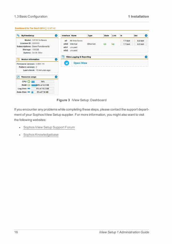
Figure 3 iView Setup: Dashboard
If you encounter anyproblemswhile completing these steps, please contact the support depart-ment of your Sophos iView Setup supplier. For more information, youmight also want to visitthe following websites:
l Sophos iView Setup Support Forum
l SophosKnowledgebase
16 iView Setup 1 Administration Guide

2 iView Setup
2.1 iView Setup MenuThe iView Setupmenu providesaccess to all configuration optionsof Sophos iView Setup, thatis, there is no need for using a command line interface to configure specific parameters.
l Dashboard: TheDashboard graphically displaysa snapshot of the current operatingstatusof the Sophos iView Setup unit.
l Management: Configure basic system and iView Setup settingsaswell as all settingsthat concern the configuration of the Sophos iView Setup unit.
l Definitions & Users: Configure network, service, and user groups for use with theSophos iView Setup unit.
l Interfaces & Routing: Configure network interfaces.
l System Logging & Reporting: View logmessagesand statistics about the utilizationof the Sophos iView Setup unit and configure settings for logging and reporting.
l Log Off: Log out of the user interface.
Searching the MenuAbove themenu a search box is located. It lets you search themenu for keywords in order toeasily findmenus concerning a certain subject. The search functionmatches the name ofmenusbut additionally allows for hidden indexed aliasesand keywords.
As soon as you start typing into the search box, themenu automatically reduces to relevantmenu entries only. You can leave the search boxat any time and click themenu entrymatchingyour prospect. The reducedmenu stays intact, displaying the search results, until you click thereset button next to it.
Tip –You can set focuson the search box via the keyboard shortcut CTRL+Y.
2.2 Button BarThe buttons in the upper right corner of iView Setup provide access to the following features:

2.3 Lists 2 iView Setup
l Username/IP: Shows the currently logged in user and the IP address fromwhich iViewSetup is accessed. If other users are currently logged in, their data will be shown, too.
l Open Live Log: Clicking this button opens the live log that is associated with the iViewSetupmenu or tab you are currently on. To see a different live log without having tochange themenu or tab, hover over the Live Log button. After some secondsa list of allavailable live logsopenswhere you can select a live log to display. Your selection ismem-orized as long as you stayon the same iView Setupmenu or tab.
Tip –You can also open live logs via theOpen Live Log buttonsprovided onmultipleiView Setup pages.
l Online Help: Everymenu, submenu, and tab hasan online help screen that providescontext-sensitive information and procedures related to the controls of the current iViewSetup page.
Note – The online help is version-based and updated bymeansof patterns. If youupdate to a new firmware version, your online help will also be updated, if available.
l Reload: To request the alreadydisplayed iView Setup page again, always click theReload button.
Note –Never use the reload button of the browser, because otherwise you will belogged out of iView Setup.
2.3 ListsManypages in iView Setup consist of lists. The buttonson the left of each list item enable you toedit, delete, or clone the item (for more information see sectionButtonsand Icons). This opensa dialog boxwhere you can define the properties of the new object.
18 iView Setup 1 Administration Guide

Figure 4 iView Setup: Example of a List
With the first drop-down list on the top you can filter all itemsaccording to their type or group.The second field on the top lets you search for itemsspecifically. Enter a search string and clickFind.
Listswith more than ten itemsare split into several chunks, which can be browsed with Forward(>>) and Backward (<<) buttons.With theDisplaydrop-down list, you can temporarily changethe number of itemsper page.
The header of a list provides some functionality. Normally, clicking a header field sorts the list forthat object field of that name, e.g. clicking the fieldName sorts the list by the objects' names. TheAction field in the header contains some batch options you can carry out on previously selectedlist objects. To select objects, select their checkbox. Note that the selection stays valid acrossmultiple pages, that is, while browsing between pagesof a list already selected objects stayselected.
Tip –Clicking on the Info icon will show all configuration options in which the object is used.
2.4 Searching in ListsA filter field helps you to quickly reduce the number of itemsdisplayed in a list. Thismakes itmuch easier to find the object(s) you were looking for.
Important Factsl A search in a list typically scans several fields for the search expression. A search in
Users & Groups for example considers the username, the real name, the comment,and the first email address. Generally speaking, the search considers all textswhich you
iView Setup 1 Administration Guide 19
2 iView Setup 2.4 Searching in Lists

2.4 Searching in Lists 2 iView Setup
can see in the list, excluding details displayed via the Info icon.
l The list search is case-insensitive. That means it makesno difference whether you enterupper- or lower-case letters. The search result will contain matchesboth with upper-case and lower-case letters. Searching explicitly for upper-case or lower-case letters isnot possible.
l The list search is based on Perl regular expression syntax (although case-insensitive).Typical search expressions known from e.g. text editors like * and ? as simple wildcardcharacters or the AND andOR operatorsdo notwork in list search.
ExamplesThe following list is a small selection of useful search strings:
Simple string:Matchesallwords that contain the given string. For example, "inter" matches"Internet", "interface", and "printer".
Beginning of a word:Mark the search expression with a \bat the beginning. For example,\bintermatches "Internet" and "interface" but not "printer".
End of a word:Mark the search expression with a \bat the end. For example, http\bmatches "http" but not "https".
Beginning of an entry:Mark the search expression with a ^at the beginning. For example,^intermatches "Internet Uplink" but not "Uplink Interfaces".
IP addresses: Searching for IP addresses, you need to escape dotswith a backslash. Forexample, 192\.168matches "192.168". To searchmore generally for IP addressesuse \dwhichmatchesanydigit. \d+matchesmultiple digits in a row. For example,\d+\.\d+\.\d+\.\d+matchesany IPv4 address.
Note – It makes sense to rather use an easy, fail-safe search expression which will lead tomorematches than to rack your brains for a supposedlymore perfect one which can easilylead to unexpected results and wrong conclusions.
You can find a detailed description of regular expressionsand their usage in Sophos iViewSetup in the SophosKnowledgebase.
20 iView Setup 1 Administration Guide

2.5 Dialog BoxesDialog boxesare specialwindowswhich are used by iView Setup to prompt you for entering spe-cific information. The example showsa dialog box for creating a new group in theDefinitions&Users>Users& Groupsmenu.
Figure 5 iView Setup: Example of a Dialog Box
Each dialog box can consist of variouswidgets such as text boxes, checkboxes, and so on. Inaddition, manydialog boxesoffer a drag-and-drop functionality, which is indicated bya specialbackground readingDND. Whenever you encounter such a box, you can drag an object intothe box. To open the object list fromwhere to drag the objects, click the Folder icon that is loc-ated right next to the text box. Depending on the configuration option, this opens the list of avail-able networks, interfaces, users/groups, or services. Clicking the green Plus icon opensa dialogwindow letting you create a new definition. Somewidgets that are not necessary for a certain
iView Setup 1 Administration Guide 21
2 iView Setup 2.5 Dialog Boxes
2.6 Buttonsand Icons 2 iView Setup
configuration are grayed out. In some cases, however, they can still be edited, but having noeffect.
Note –Youmayhave noticed the presence of bothSave andApplybuttons in iView Setup.TheSave button is used in the context of creating or editing objects in iView Setup such asstatic routesor network definitions. It is alwaysaccompanied byaCancelbutton. TheApplybutton, on the other hand, serves to confirm your settings in the backend, thuspromptly activ-ating them.
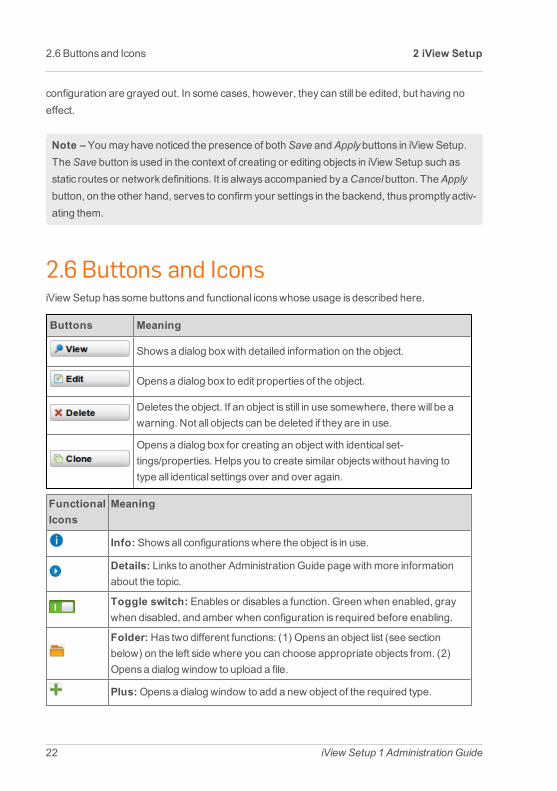
2.6 Buttons and IconsiView Setup has some buttonsand functional iconswhose usage is described here.
Buttons Meaning
Showsa dialog boxwith detailed information on the object.
Opensa dialog box to edit properties of the object.
Deletes the object. If an object is still in use somewhere, there will be awarning. Not all objects can be deleted if theyare in use.
Opensa dialog box for creating an object with identical set-tings/properties. Helps you to create similar objectswithout having totype all identical settingsover and over again.
FunctionalIcons
Meaning
Info: Showsall configurationswhere the object is in use.
Details: Links to another Administration Guide page with more informationabout the topic.
Toggle switch: Enablesor disablesa function. Green when enabled, graywhen disabled, and amber when configuration is required before enabling.
Folder: Has two different functions: (1) Opensan object list (see sectionbelow) on the left side where you can choose appropriate objects from. (2)Opensa dialog window to upload a file.
Plus:Opensa dialog window to add a new object of the required type.
22 iView Setup 1 Administration Guide

FunctionalIcons
Meaning
Action:Opensa drop-downmenuwith actions. The actionsdepend on thelocation of the icon: (1) Icon in list header: the actions, e.g.,Enable,Disable,Delete, apply to the selected list objects. (2) Icon in text box: with the actionsImport andExport you can import or export text, and withEmpty you deletethe entire content. There is also a filter field which helps you to drill down a listto relevant elements. Note that the filter is case-sensitive.
Empty: Removesan object from the current configuration when located infront of the object. Removesall objects from a boxwhen located in theActionsmenu. Objects are however never deleted.
Import:Opensa dialog window to import text with more than one item or line.Enhancesaddingmultiple itemswithout having to type them individually, e.g. alarge blacklist to the URL blacklist. Copy the text from anywhere and enter itusing CTRL+V.
Export:Opensa dialog window to export all existing items. You can select adelimiter to separate the items, which can either be new line, colon, or comma.To export the itemsas text, mark the whole text in theExported Text field andpressCTRL+C to copy it. You can then paste it into all common applicationsusing CTRL+V, for example a text editor.
Sort: Using these two arrows, you can sort list elements bymoving an ele-ment down or up, respectively.
Forward/Backward: Depending on the location you can navigate throughthe pagesof a long list, or move backand forth along the history of changesand settings.
PDF: Saves the current view of data in a PDF file and then opensa dialog win-dow to download the created file.
CSV: Saves the current view of data in a CSV (comma-separated values) fileand then opensa dialog window to download the created file.
2.7 Object ListsAn object list is a drag-and-drop list which is temporarily displayed on the left side ofWebAdmin,covering themainmenu.
iView Setup 1 Administration Guide 23
2 iView Setup 2.7 Object Lists

2.7 Object Lists 2 iView Setup
Figure 6 iView Setup: Dragging anObject From theObject ListNetworks
An object list is opened automaticallywhen you click the Folder icon (see section above).
The object list gives you quick access to iView Setup objects like users/groups, interfaces, net-works, and services to be able to select them for configuration purposes. Objects are selectedsimply bydragging and dropping them onto the current configuration.
According to the different existing object types, there are five different typesof object lists. Click-ing the Folder icon will alwaysopen the type required by the current configuration.
24 iView Setup 1 Administration Guide

3 DashboardTheDashboard graphically displaysa snapshot of the current operating statusof Sophos iViewSetup.With help of the Dashboard Settings icon on the top right you can, amongst others, con-figure which topic sectionsare displayed.
The Dashboard is displayed when you log in to iView Setup and shows the following informationbydefault:
l General Information: Hostname,model, license ID1, subscriptions, storage anduptime of the unit. The display color of a subscription switches to orange 30 daysbeforeits expiration date. During the last 7 daysand after expiration, a subscription is displayedin red.
l Version Information: Information on the currently installed firmware and pattern ver-sionsaswell as available updates.
l Resource Usage: Current system utilization, including the following components:
l TheCPU2utilization in percent
l TheRAM3utilization in percent. Please note that the totalmemorydisplayed is thepart that is usable by the operating system.With 32-bit systems, in some cases thatdoesnot represent the actual size of the physicalmemory installed, aspart of it isreserved for hardware.
l The amount of hard disk space consumed by the log partition in percent
l The amount of hard disk space consumed by the root partition in percent
l The statusof the UPS4 (uninterruptible power supply) module (if available)
l Interfaces: Name and statusof configured network interface cards. In addition, inform-ation on the average bit rate of the last 75 seconds for both incoming and outgoing trafficis shown. The valuespresented are obtained from bit rate averagesbased on samplesthat were taken at intervals of 15 seconds. Clicking a traffic value of an interface opensaFlowMonitor in a new window. The FlowMonitor displays the traffic of the last ten
1Identity2Central Processing Unit3RandomAccessMemory4Uninterruptible Power Supply
3.1 Flow Monitor 3 Dashboard
minutesand refreshesautomatically at short intervals. For more information on the FlowMonitor see chapter FlowMonitor.
l iView Logging & Reporting: Possibility to open iView. Clicking on the arrow buttonopens the iView Logging & Reporting.
3.1 FlowMonitorThe FlowMonitor of Sophos iView Setup is an application which givesquick access to inform-ation on network traffic currently passing the interfacesof iView Setup. It can be easily accessedvia the Dashboard by clicking one of the interfacesat the top right. By clickingAll Interfaces theFlow Monitor displays the traffic accumulated on all active interfaces. By clicking a single inter-face, the Flow Monitor displays the traffic of this interface only.
Note – The FlowMonitor opens in a new browser window. Aspop-up blockers are likely toblock thiswindow it is advisable to deactivate pop-up blockers for iView Setup.
The FlowMonitor provides two views, a chart and a table, which are described in the next sec-tions. It refreshesevery five seconds. You can click thePause button to stop refreshing. AfterclickingContinue to start refreshing again, the Flow Monitor updates to the current traffic inform-ation.
Tabular ViewThe FlowMonitor table provides information on network traffic for the past five seconds:
#: Traffic is ranked based on its current bandwidth usage.
Application: Protocol or name of the network traffic if available. Unclassified traffic is a type oftraffic unknown to the system. Clicking an application opensa window which provides inform-ation on the server, the port used, bandwidth usage per server connection, and total traffic.
Clients: Number of client connectionsusing the application. Clicking a client opensa windowwhich provides information on the client's IP address, bandwidth usage per client connection,and total traffic. Note that with unclassified traffic the number of clients in the tablemaybehigher than the clients displayed in the additional information window. This is due to the fact thatthe term "unclassified" comprisesmore than one application. So, theremight be only one clientin the information window but three clients in the table, the latter actually being the connectionsof the single client to three different, unclassified applications.
26 iView Setup 1 Administration Guide

Bandwidth Usage Now: The bandwidth usage during the last five seconds. Clicking a band-width opensa window which provides information on the download and upload rate of theapplication connection.
Total Traffic: The total of network traffic produced during the "lifetime" of a connection.Example 1: A download started some time in the past and still going on: the whole traffic pro-duced during the time from the beginning of the download will be displayed. Example 2: Severalclients using facebook: as long asone client keeps the connection open, the traffic produced byall clients so far addsup to the total traffic displayed.
Clicking a total traffic opensa window which provides information on the overall download andupload rate of the application connection.
Chart ViewThe FlowMonitor chart displays the network traffic for the past tenminutes. The horizontal axisreflects time, the vertical axis reflects the amount of trafficwhile dynamically adapting the scaleto the throughput.
At the bottom of the chart view a legend is located which refers to the type of traffic passing aninterface. Each type of traffic hasa different color so that it can be easily distinguished in thechart.
When hovering themouse cursor on a chart a big dot will appear, which givesdetailed inform-ation of this part of the chart. The dot is clung to the line of the chart. As youmove themousecursor the dot follows. In case a chart has several lines, the dot switchesbetween them accord-ing to where youmove themouse cursor. Additionally, the dot changes its color depending onwhich line its information refer to, which is especially usefulwith lines running close to eachother. The dot provides information on type and size of the traffic at the respective point of time.
iView Setup 1 Administration Guide 27
3 Dashboard 3.1 Flow Monitor


4ManagementThis chapter describeshow to configure basic system settingsaswell as the settingsof the web-based administrative interface of Sophos iView Setup among others. TheOverview pageshowsstatistics of the last iView Setup sessions including possible changes. Click theShow but-ton in theChangelog column to view the changes in detail.
In theState column, the end timesof previous iView Setup sessionsare listed.
Note –You can end an iView Setup session by clicking the Log offmenu. If you close thebrowser without clicking the Log offmenu, the session timesout after the time span definedon theManagement > iView Setup Settings>Advanced tab.
The following topics are included in this chapter:
l SystemSettings
l iView Setup Settings
l iView Logging &Reporting
l Licensing
l Up2Date
l Backup/Restore
l Shutdown/Restart
4.1 System SettingsThe system settingsmenu allowsyou to configure basic settingsof your iView Setup. You canset hostname, date and time settingsaswell as scan settings for antivirus engine or advancedthreat protection options. Configuration or password resets and SSH shell access con-figurations can also be done.

4.1 SystemSettings 4 Management
4.1.1 OrganizationalEnter these organizational information (if not yet done in the InstallationWizard):
l Organization Name: name of your organization
l City: location of your organization
l Country: country your organization is located
l Adminitrator's Email Address: email address to reach the person or group technicallyresponsible for the operation of your Sophos iView Setup
Note that this data is also used in certificates foriView Setup.
4.1.2 HostnameEnter the hostname of your iView Setup asa fully qualified domain name (FQDN). The fully qual-ified domain name is an unambiguousdomain name that specifies the node's absolute positionin the DNS tree hierarchy, for exampleiviewsetup.example.com. A hostnamemaycontainalphanumeric characters, dots, and hyphens. At the end of the hostname theremust be a spe-cial designator such ascom, org, or de. The hostnamewill be used in notificationmessages toidentify iView Setup. Note that the hostname doesnot need to be registered in the DNS zonefor your domain.
4.1.3 Time and DateOn your iView Setup, date and time should alwaysbe set correctly. This is needed both for get-ting correct information from the logging and reporting systemsand to assure interoperabilitywith other computers on the Internet.
Usually, you do not need to set the time and datemanually. Bydefault, automatic syn-chronization with public Internet time servers is enabled (see sectionSynchronize TimewithInternet Server below).
In the rare case that you need to disable synchronization with time servers, you can change thetime and datemanually. However, when doing so, payattention to the following caveats:
l Never change the system time from standard time to daylight saving time or vice versa.This change is alwaysautomatically covered by your time zone settingseven if automaticsynchronization with time servers is disabled.
30 iView Setup 1 Administration Guide

l Never change date or timemanuallywhile synchronization with time servers is enabled,because automatic synchronization would typically undo your change right away. In caseyoumust set the date or timemanually, remember to first remove all servers from theNTPServersbox in theSynchronize Timewith Internet Server section below and clickApply.
l After manually changing the system time, wait until you see the green confirmationmes-sage, stating that the change wassuccessful. Then reboot the system (Management >Shutdown/Restart). This is highly recommended asmanyservices rely on the fact thattime is changing continuously, not abruptly. Jumps in time thereforemight lead tomal-function of various services. This advice holdsuniversally true for all kind of computer sys-tems.
l In rare cases, changing the system timemight terminate your iView Setup session. Incase this happens, log in again, checkwhether the time is now correctly set and restartthe system afterwards.
If you operatemultiple interconnected iView Setups that span several time zones, select thesame time zone for all devices, for example UTC (Coordinated Universal Time)—thiswillmakelogmessagesmuch easier to compare.
Note that when youmanually change the system time, you will encounter several side-effects,even when having properly restarted the system:
l Turning the clock forwardl Time-based reportswill contain no data for the skipped hour. In most graphs, this
time span will appear asa straight line in the amount of the latest recorded value.
l Turning the clock backwardl There is already log data for the corresponding time span in time-based reports.
l Most diagramswill display the values recorded during this period as compressed.
l The elapsed time since the last pattern check (asdisplayed on the Dashboard)shows the value "never", even though the last checkwas in fact only a few minutesago.
l Automatically created certificateson iView Setupmaybecome invalid because thebeginning of their validity periodswould be in the future.
Because of these drawbacks the system time should only be set once when setting up the sys-temwith only small adjustments beingmade thereafter. This especially holds true if reportingdata needs to be processed further and accuracyof the data is important.
iView Setup 1 Administration Guide 31
4 Management 4.1 SystemSettings
4.1 SystemSettings 4 Management
Set Date and TimeTo configure the system timemanually, select date and time from the respective drop-downlists. ClickApply to save your settings.
Set Time ZoneTo change the system's time zone, select an area or a time zone from the drop-down list. ClickApply to save your settings.
Changing the time zone doesnot change the system time, but only how the time is representedin output, for example in logging and reporting data. Even if it doesnot disrupt services, wehighly recommend to reboot afterwards tomake sure that all servicesuse the new time setting.
Synchronize Time with Internet ServerTo synchronize the system time using a timeserver, select one or more NTP1 servers. ClickApplyafter you have finished the configuration.
NTP Servers: TheNTPServer Pool is selected bydefault. This network definition is linked tothe big virtual cluster of public timeservers of the pool.ntp.org project. In case your Internet ser-vice provider operatesNTP servers for customersand you have access to these servers, it isrecommended to remove theNTPServer Pooland use your provider's servers instead.Whenchoosing your own or your provider's servers, usingmore than one server is useful to improveprecision and reliability. The usage of three independent servers is almost always sufficient.Addingmore than three servers rarely results in additional improvements, while increasing thetotal server load. Using bothNTPServer Pooland your own or your provider's servers is notrecommended because it will usually neither improve precision nor reliability.
Test Configured Servers: Click this button if you want to test whether a connection to theselected NTP server(s) can be established from your device and whether it returnsusable timedata. Thiswillmeasure the time offset between your system and the servers. Offsets shouldgenerally be well below one second if your system is configured correctly and hasbeen oper-ating in a stable state for some time.
Right after enabling NTPor adding other servers, it is normal to see larger offsets. To avoidlarge time jumps, NTPwill then slowly skew the system time, such that eventually, it will becomecorrect without any jumping. In that situation, please be patient. In particular, in this case, do not
1NetworkTime Protocol
32 iView Setup 1 Administration Guide
restart the system. Rather, return to checkabout an hour later. If the offsets decrease, all isworking as it should.
4.1.4 Shell AccessSecure Shell (SSH) is a command-line accessmode primarily used to gain remote shell accessto iView Setup. It is typically used for low-levelmaintenance or troubleshooting. To access thisshell you need an SSH client, which usually comeswith most Linuxdistributions.
Allowed NetworksUse theAllowed networks control to restrict access to this feature to certain networksonly. Net-works listed here will be able to connect to the SSH service.
Authent icat ionIn this section you can define an authenticationmethod for SSH accessand the strictnessofaccess. The following authenticationmethodsare available:
l Password (default)
l Public key
l Password and public key
To use this optionsactivate the concerning checkmarks. To usePublicKeyAuthentication youneed to upload the respective public key(s) into the fieldAuthorized keys for loginuser for eachuser allowed to authenticate via their public key(s).
Allow Root Login: You can allow SSH access for the root user. This option is disabled bydefault as it leads to a higher security risk.When this option is enabled, the root user is able tologin via their public key. Upload the public key(s) for the root user into the fieldAuthorized keysfor root.
ClickApply to save your settings.
Shell User PasswordsEnter passwords for the default shell accountsrootand loginuser. To change the passwordfor one out of these two accounts only, just leave both input boxes for the other account blank.
Note – To enable SSH shell access, passwordsmust be set initially.
iView Setup 1 Administration Guide 33
4 Management 4.1 SystemSettings

4.1 SystemSettings 4 Management
SSH Daemon Lis ten PortThis option lets you change the TCPport used for SSH. Bydefault, this is the standard SSH port22. To change the port, enter an appropriate value in the range from 1024 to 65535 in thePortnumber boxand clickApply.
4.1.5 Reset Configuration or PasswordsThe optionson theReset Configuration or Passwords tab let you delete the passwordsof theshell users. In addition, you can execute a factory reset, and you can reset the iView Setup's sys-tem ID.
Reset System PasswordsExecuting theReset SystemPasswordsNow function will reset the passwordsof the followingusers:
l root (shell user)
l loginuser (shell user)
l admin (predefined administrator account)
In addition, to halt the system, select theShutdown system afterwardsoption.
Security Note – The next person connecting to the iView Setup will be presented anAdminPassword Setup dialog window. Thus, after resetting the passwords, you should usuallyquickly log out, reload the page in your browser, and set a new admin password.
Besides, shell accesswill not be possible anymore until you set new shell passwordson theMan-agement >SystemSettings>Shell Access tab.
Factory ResetTheRun FactoryReset Now function resets the device back to the factory default configuration.The following data will be deleted:
l System configuration
l Logsand reporting data
l Update packages
34 iView Setup 1 Administration Guide

l Licenses
l Passwords
However, the version number of Sophos iView Setup Software will remain the same, that is, allfirmware and pattern updates that have been installed will be retained.
Note –Sophos iView Setup will shut down once a factory reset hasbeen initiated.
4.2 GeneralOn the iView Setup Settings>General tab you can configure the iView Setup language andbasic access settings.
iView Setup LanguageSelect the language of iView Setup. The selected language will also be used for some iViewSetup output, e.g., the executive report. Note that this setting is global and applies to all users.ClickApply to save your settings.
After changing the language, it might be necessary to empty your browser cache tomake surethat all texts are displayed in the correct language.
iView SetupAccess Configurat ionHere you can configure which users and/or networks should have access to iView Setup.
Allowed Administrators: Sophos iView Setup can be administered bymultiple administratorssimultaneously. In theAllowed Administratorsbox you can specifywhich users or groups shouldhave unlimited read and write access to the iView Setupinterface. Bydefault, this is the group ofSuperAdmins. How to add a user is explained on theDefinitions&Users>Users&Groups>Userspage.
Allowed Networks: TheAllowed Networksbox lets you define the networks that should beable to connect to the iView Setup interface. For the sake of a smooth installation of iViewSetup, the default isAny. Thismeans that the iView Setup interface can be accessed fromeverywhere. Change this setting to your internal network(s) as soon aspossible. Themostsecure solution, however, would be to limit the access to only one administrator PC throughHTTPS. How to add a definition is explained on theDefinitions&Users>NetworkDefinitions>NetworkDefinitionspage.
iView Setup 1 Administration Guide 35
4 Management 4.2 General
4.2 General 4 Management
Log Access Traffic: If you want to log all iView Setupaccessactivities in the firewall log, selectthe Log AccessTraffic checkbox.
4.2.1 HTTPS CertificateOn theManagement > iView Setup Settings>HTTPSCertificate tab you can import the iViewSetup CA certificate into your browser, regenerate the iView Setup certificate, or choose asigned certificate to use for iView Setup.
During the initial setup of the iView Setup access you have automatically created a localCA1 cer-tificate on iView Setup. The public keyof thisCA certificate can be installed into your browser toget rid of the securitywarningswhen accessing the iView Setup interface.
To import the CA certificate, proceed as follows:
1. On the HTTPS Certificate tab, click Import CA Certificate.
The public keyof the CA certificate will be exported.
You can either save it to disk or install it into your browser.
2. Install the certificate (optional).
The browser will open a dialog box letting you choose to install the certificate immediately.
Note –Due to different system timesand time zones the certificatemight not be valid directlyafter its creation. In this case, most browserswill report that the certificate hasexpired, whichis not correct. However, the certificate will automatically become valid after amaximum of 24hours and will stay valid for 27 years.
Re-generate iView Setup Cert ificateThe iView Setup certificate refers to the hostname you have specified during the initial login. Ifthe hostname hasbeen changed in themeantime, the browser will display a securitywarning.To avoid this, you can create a certificate taking the new hostname into account. For that pur-pose, enter the hostname asdesired and clickApply. Note that due to the certificate change, tobe able to continue working in iView Setup, you probably need to reload the page via your webbrowser, accept the new certificate, and log back into iView Setup.
1Certificate Authority
36 iView Setup 1 Administration Guide
Choose iView Setup Cert ificateIf you do not want to import the CA certificate but instead use your own signed certificate foriView Setup, you can select it here. To use a certificate, select it from theCertificatesdrop-downlist and clickApply.
4.2.2 Advanced
iView Setup Idle TimeoutLog Out After: In this field you can specify the period of time (in seconds) how long an iViewSetup session can remain idle before the administrator is forced to log in again. Bydefault, theidle timeout is set to 1,800 seconds. The range is from 60 to 86,400 seconds.
Log Out on Dashboard: Bydefault, when you have opened theDashboard page of iViewSetup, the auto logout function is enabled. You can, however, select this option to disable theauto logout function for Dashboard only.
iView Setup TCP PortBydefault, port 4444 is used as iView Setup TCPport. In the TCPPort box you can enter either443or any value between 1024and 65535. However, certain ports are reserved for other ser-vices. Note that youmust add the port number to the IP address (separated bya colon) in thebrowser's addressbar when accessing iView Setup, for examplehttps://192.168.0.1:4444
4.3 iView Logging & ReportingThe iView Logging & Reportingmenu allowsyou to configure general settings for iView andopen iView directly. You can configure the port on which iView is reachable, the remote syslogserver and you can set the password of the iView administrator.
4.3.1 GeneralThis tab allowsyou to configure general data of iView such asport, admin password andUDP port.
iView Setup 1 Administration Guide 37
4 Management 4.3 iView Logging &Reporting

4.4 Licensing iView 4 Management
iView Sett ingsBydefault, port 8000 is used as iView port. In the iView Port field you can enter any valuebetween 1024and 65535. However, certain ports are reserved for other services. In particular,you can never use port 10443. Note that youmust add the port number to the IP address (sep-arated bya colon) in the browser's addressbar when accessing iView, for examplehttps://192.168.0.1:8000. TheAllowed Networksbox lets you define the networks thatshould be able to connect to the iView interface. For the sake of a smooth installation of iViewSetup, the default isAny. Thismeans that the iView interface can be accessed from every-where. ClickApply to save your settings.
Remote Sys log ServerBydefault, UDPport 514 is used asRemote Syslog Server port. In theRemote Syslog ServerPort field you can enter any value between 1024and 65535. TheAllowed Devicesbox lets youdefine the hosts or networks that should be able to connect to the remote syslog server. ClickApply to save your settings.
iView Admin PasswordEnter the requested password into thePassword field and repeat it in theRepeat field. ClickApply to save your settings. The new password is active now.
4.3.2 Open iViewAll central logging and reporting functionality is available in the iView application itself. To open it,either enter the IP addresswith the port you configured on the tab iView Logging & Reporting> Generalor press theOpen iView button.
4.4 Licensing iViewThe availability of certain featureson Sophos iView Setup is defined by licensesand sub-scriptions, i.e. the licensesand subscriptions you have purchased with your iView Setup enableyou to use certain featuresand others not.
38 iView Setup 1 Administration Guide

4.4.1 How to Obtain a LicenseSophos iView Setup shipswith a Base License with all featuresenabled. The Base License isunlimited with 100GB storage and 30 daysSupport included. All licensesare created in theMyUTMPortal.
Once you have received the activation keysbyemail after purchasing an iView Setup license,youmust use these keys in order to create your license or upgrade an existing license. To activ-ate a license, you have to log in to theMyUTMPortal and visit the licensemanagement page. Atthe top of the page is a formwhere you can cut and paste the activation key from the email intothis field. For more information see theMyUTM User Guide.
Figure 7 MyUTMPortal
Another form appears asking you to fill in information about the reseller you purchased thelicense from aswell as your own details. The portal tries to pre-fill asmuch of this form aspos-sible. After submitting this form, your license is created, and you are forwarded to the licensedetail page to download the license file.
To actually use the license, youmust download the license file to your hard drive and then log into your iView Setup installation. In iView Setup, navigate to theManagement > Licensing >Installation tab and use the upload function to find the license text file on your hard drive. Upload
iView Setup 1 Administration Guide 39
4 Management 4.4 Licensing iView

4.4 Licensing iView 4 Management
the license file, and iView Setup will process it to activate any subscriptionsand other settingsthat the license outlines.
Note – The activation key you received byemail cannot be imported into iView Setup. Thiskey is only used to activate the license. Only the license file can be imported to iView Setup.
4.4.2 Licensing ModelThe licensingmodel of Sophos is very easy. First, there is the base license, providing all func-tionsand 100GB storage. Second, there are three additional subscriptions:
l 1 TB storage
l 8 TB storage
l unlimited storage
Those can be purchased separately.
For more detailed information on subscriptionsand their feature set please refer to your cer-tified iView Setup Partner or the Sophos iView Setup webpage.
Up2DatesEach subscription enables full automatic update support, i.e. you will be automatically informedabout new firmware updates. Also, firmware and pattern updates can be downloaded (andinstalled) automatically.
A base license without any subscriptions supports only limited automatic updates: solely patternupdates such asonline help updatesand the like will continue to be downloaded and installedautomatically. You will, however, not be informed about available firmware updates, and thefirmware updateshave to be downloadedmanually. Announcements for new firmwareupdates can be found in the Sophos iView Setup Up2Date Blog.
Support and MaintenanceThe base license comeswithWebSupport. You can use the Sophos iView Setup SupportForum and the SophosKnowledgebase.
As soon as you purchase one of the subscriptions you will be automatically upgraded toStand-ard Support, where you can additionally open a support case inMyUTMPortal or contact yourcertified iView Setup Partner.
40 iView Setup 1 Administration Guide

There is also the possibility to purchase aPremiumSupport subscription, which offers 24/7 sup-port with an iView Setup Engineer being your contact person.
4.4.3 OverviewThe Licensing >Overview tab providesdetailed information about your license and is dividedintomultiple areas:
l Base License: Showsbasic license parameters such as ID, registration date, or type.
l Support Services: Shows the support level plus the date until it is valid. For iView SetupWebSupport,Standard Support andPremiumSupport are available.With the BaseLicense you haveWebSupport automatically.
4.4.4 InstallationOn theManagement > Licensing > Installation tab you can upload and install a new license.
To install a license, proceed as follows:
1. Open the Upload File dialog window.
Click the Folder icon next to the License file box.
TheUpload File dialog window opens.
2. Select the license file.
Browse to the directorywhere your license file resides.
Select the license file you want to upload.
3. Click Start Upload.
Your license file will be uploaded.
4. Click Apply.
Your license will be installed. Note that the new license will automatically replace anyother license already installed.
The installation of the license will take approximately 60 seconds.
iView Setup 1 Administration Guide 41
4 Management 4.4 Licensing iView
4.5 Up2Date 4 Management
4.5 Up2DateTheManagement >Up2Datemenu allows the configuration of the update service of SophosiView Setup. Regularly installed updates keep your iView Setup up-to-date with the latest bug-fixes, product improvements, and virus patterns. Each update is digitally signed bySophos—anyunsigned or forged update will be rejected. Bydefault new update packagesare auto-matically downloaded to iView Setup. This option can be configured in theManagement >Up2Date >Configurationmenu.
l Firmware updates: A firmware update contains bug-fixesand feature enhancementsfor Sophos iView Setup Software.
In order to download Up2Date packages, iView Setup opensa TCP1 connection to the updateservers on port 443—allowing this connection without anyadjustment to bemade by the admin-istrator. However, if there is another firewall in between, youmust explicitly allow the com-munication via the port 443TCP to the update servers.
4.5.1 OverviewTheManagement >Up2Date >Overview tab providesa quick overview whether your system isup-to-date. From here, you can install new firmware and pattern updates.
Up2Date ProgressThis section is only visible when you have triggered an installation process. Click the buttonWatch Up2Date Progress in NewWindow to monitor the update progress. If your browserdoesnot suppresspop-up windows, a new window showing the update progresswill beopened. Otherwise you will have to explicitly allow the pop-up window.
Note –Abackup will be sent to the standard backup email recipients before an installationprocess is started.
FirmwareThe Firmware section shows the currently installed firmware version. If an update package isavailable, a buttonUpdate to Latest Version Now is displayed. Additionally, you will see a
1Transmission Control Protocol
42 iView Setup 1 Administration Guide

message in theAvailable Firmware Up2Dates section. You can directly download and install themost recent update from here. Once you have clickedUpdate To Latest Version Now, you canwatch the update progress in new awindow. For this, click theReload button of iView Setup.
Available F irmware Up2DatesIf you have selectedManualon theConfiguration tab, you can see aCheck for Up2Date Pack-agesNow button in this section, which you can use to download firmware Up2Date packagesmanually. If there aremore than one Up2Datesavailable, you can select which one you aregoing to install. You can use theUpdate to Latest Version Now button in the Firmware section ifyou want to install themost recent version directly.
There is aSchedule button available for each Up2Date with which you can define a specific dateand time where an update is to be installed automatically. To cancel a scheduled installation,clickCancel.
A note on "implicit" installations: There can be a constellation, where you schedule an Up2Datepackage which requiresan older Up2Date package to be installed first. ThisUp2Date packagewill be automatically scheduled for installation before the actualUp2Date package. However,you can define a specific time for this package, too, but you cannot prevent its installation.
PatternThePattern section shows the current version of the installed patterns. If you have selectedManualon theConfiguration tab, you can see aUpdate PatternsNow button. Use this button todownload and install new patterns if available.
Note – The current pattern version doesnot need to be identicalwith the latest available pat-tern version in order for the iView Setup unit to be working correctly. A deviation between thecurrent and the latest available pattern versionmight occur when new patternsare available,which, however, do not apply to the unit you are using.What patternsare downloaded isdependent on your settingsand hardware configuration.
4.5.2 ConfigurationBydefault, new update packagesare automatically downloaded to iView Setup.
Firmware Download IntervalThis option is set to 15minutesbydefault, that isSophos iView Setup checksevery 15minutesfor available firmware updates. Sophos iView Setup will automatically download (but not install)
iView Setup 1 Administration Guide 43
4 Management 4.5 Up2Date

4.5 Up2Date 4 Management
available firmware update packages. The precise time when this happens is distributed ran-domlywithin the limits of the selected interval. You can change the interval up toMonthlyor youcan disable automatic firmware download by selectingManual from the drop-down list. If youselectManual you will find aCheck for Up2Date PackagesNow button on theOverview tab.
4.5.3 AdvancedTheManagement >Up2Date >Advanced tab lets you configure further Up2Date options suchas selecting a parent proxyor Up2Date cache for your iView Setup.
Note –Update packages can be downloaded from Sophos iView Setup FTP server.
Manual Up2Date Package Upload: If your iView Setup doesnot have direct access to theInternet or an Up2Date cache to download new update packagesdirectly, you can upload theupdate packagemanually. To do so, proceed as follows:
1. Open the Upload File dialog window.
Click the Folder icon next to theUp2Date file box.
TheUpload File dialog window opens.
2. Select the update package.
ClickBrowse in theUpload File dialog window and select the update package you want toupload.
3. Click Start Upload.
The update package will be uploaded to iView Setup.
4. Click Apply.
Your settingswill be saved.
Parent ProxyAparent proxy is often required in those countries that require Internet access to be routedthrough a government-approved proxy server. If your security policy requires the use of a par-ent proxy, you can set it up here by selecting the host definition and port.
Use a parent proxy:
44 iView Setup 1 Administration Guide

1. Select the checkbox to enable parent proxy use.
2. Select or add the host.
3. Enter the port of the proxy.
How to add a definition is explained on theDefinitions&Users>NetworkDefinitions>NetworkDefinitionspage.
4. Click Apply.
Your settingswill be saved.
Proxy requires authentication: If the parent proxy requiresauthentication, enter usernameand password here.
If a parent proxy is configured, Sophos iView Setup fetchesboth firmware and patternUp2Dates from it.
4.6 Backup/RestoreThe backup restoring function allowsyou to save the iView Setup settings to a file on a local disk.This backup file allowsyou to install a known good configuration on a new or misconfigured sys-tem.
Be sure tomake a backup after every system change. Thiswill ensure that themost current set-tingsare alwaysavailable. In addition, keep your backups in a safe place, as it also containssecurity-relevant data such as certificatesand cryptographic keys. After generating a backup,you should always check it for readability. It is also a good idea to use an external program togenerateMD5 checksums, for thiswill allow you to check the integrity of the backup later on.
4.6.1 Backup/RestoreOn theManagement >Backup/Restore >Backup/Restore tab you can create backups, importbackups, aswell as restore, download, send, and delete existing backups.
Available BackupsThis section is only visible if at least one backup hasbeen created before, either by the auto-matic backup function or manually (see sectionCreate Backup).
iView Setup 1 Administration Guide 45
4 Management 4.6 Backup/Restore
4.6 Backup/Restore 4 Management
All backupsare listed giving date and time of their creation, their iView Setup version number,the user who created it, and the comment.
You can decide whether to download, restore, delete, or send a backup.
l Download:Opensa dialog window where you can decide to download the file encryp-ted (provide password) or unencrypted. ClickDownload Backup. You are prompted toselect a location in the file system for the downloaded backup to reside.
l Encrypt before downloading: Before downloading or sending it, you have theoption to encrypt the backup. Encryption is realized with Blowfish cipher in CBC1
mode. Provide a password (second time for verification). You will be asked for thispassword when importing the backup. The file extension for encrypted backups isebf, for unencrypted backupsabf.
Note –Abackup does include administrator passwords, the high availabilitypassphrase if configured, aswell as all RSA keysand X.509 certificates. Sincethis information is confidential, it is good practice to enable encryption.
l Restore: Replaces the current system settingsby the settings stored in a backup. Youwill have to log in again afterwards. If the selected backup contains all data you can log indirectly. If the selected backup doesnot contain all data (see sectionCreate Backup) youwill have to enter the necessary data during the login procedure. If only the host data hasbeen removed in the selected backup you can add an additional administrative emailaddress if you want. It will be used where no recipient is given and asadditional addresswheremultiple recipients are possible.
Note –Backup restoration is only backward compatible. Only backups from versionssmaller than the current one are considered functional.
l Restoring backups fromUSB flash drive: You can also restore unencryptedbackup files (file extension abf) from a FAT2 formatted USB3 flash drive such asasimple USB stick. To restore a backup from aUSB flash drive, copy the backup fileto the USB flash drive and plug the device into Sophos iView Setup prior to boot
1Cipher BlockChaining2File Allocation Table3UniversalSerial Bus
46 iView Setup 1 Administration Guide

up. If several backup files are stored on the device, the lexicographically first file willbe used (numbersprecede letters). During the boot up, the second file will be usedbecause it beginswith a number, although it ismuch older than the other one.
In addition, a lock file is created after the successful recovery of a backup, pre-venting the installation of the same backup over and over again while the USBflash drive is still being plugged in. However, if you want to install a previousbackuponce again, youmust first reboot with no USB flash drive plugged in. Thiswilldelete all lock files.When you now boot with the USB flash drive plugged in again,the same backup can be installed.
l Delete: Deletesa backup from the list. Using the Delete icon on the bottom of the list, youcan delete all selected backups. To select backups, click the checkboxes to the left of thebackupsor use the checkboxon the bottom to select all backups.
l Send: In a dialog window you can specify the email recipients. Bydefault, the address(es) provided on theAutomaticBackups tab are selected. Then decide if you want tosend the file encrypted (provide password) or unencrypted. ClickSendNow to send thebackup.
l Encrypt before sending: SeeEncrypt before downloading above.
Create BackupBackupsare not only useful to restore your system after an (unwanted) change or failure.Moreover, they can be used as templates to set up systems that should have a similar con-figuration so that those systemsare alreadypre-configured in somewaywhich can save you alot of time. For that, you can strip certain information from a backup before it is created, e.g. host-name, certificates, etc.
To create a backup with the current system state, proceed as follows:
1. In the Create Backup section, enter a comment (optional).
The comment will be displayed along with the backup in the backup list.
2. Make the following settings (optional):
Remove unique site data: Select this option to create the backup without host-specificdata. This includeshostname, system ID, license aswell as all certificates, public andprivate keys.
iView Setup 1 Administration Guide 47
4 Management 4.6 Backup/Restore

4.6 Backup/Restore 4 Management
Such backupsare a convenient means to set upmultiple similar systems. There aresome things to consider though: 1) After restoring you are presented the basic systemsetup. 2) Only the first interface is configured, the primary IP addressbeing the one thathasbeen configured during installation. All other interfaceswill be disabled and set to IPaddress0.0.0.0.
Caution –Althoughmost of the host-specific data is being removed, such a backuptemplate still contains confidential information, such asuser passwords. Therefore it isgood practice to alwaysencrypt it.
Remove administrative mail addresses: Select this option to additionally remove theadministrator email addressesused in variousparts of iView Setup, e.g. postmasteraddresses. This option is especially useful for IT partnerswho set up Sophos iView Setupdevicesat customers' sites.
3. Click Create Backup Now.
The backup appears in the list of available backups.
If a backup is created with one or both of the options selected, the backup entry containsa respective additional comment.
Note – TheHA settingsare part of the hardware configurationsand cannot be savedin a backup. Thismeans that the HA settingswill not be overwritten bya backuprestore.
Import BackupTo import a backup, proceed as follows:
1. Click the Folder icon and select a backup file to upload.
2. Click Start Upload.
3. Decrypt the backup.
If you want to upload an encrypted backup file, youmust provide the correct passphraseprior to importing the backup.
4. Click Import Backup to import the backup.
Note that the backup will not instantly be restored. Instead, it will be added to theAvail-able Backups list.
48 iView Setup 1 Administration Guide
4.6.2 Automatic BackupsOn theManagement >Backup/Restore >AutomaticBackup tab you can configure severaloptionsdealing with the automatic generation of backups. To have backups created auto-matically, proceed as follows:
1. Enable automatic backups on the Automatic Backups tab.
Click the toggle switch.
The toggle switch turnsgreen and theOptionsandSend BackupsbyEmailareasbecome editable.
2. Select the interval.
Automatic backups can be created at various intervals.
You can choose between daily, weekly, andmonthly.
3. Specify the maximum number of backups to be stored.
Automatically created backupsare stored up to the number you enter here. Once themaximum hasbeen reached, the oldest automatic backupswill be deleted.
Note that this applies to automatically created backupsonly. Backups createdmanuallyand backups created automatically before a system update will not be deleted.
4. Click Apply.
Your settingswill be saved.
The toggle switch turnsgreen.
To save you the work of backing up your iView Setupmanually, the backup feature supportsemailing the backup file to a list of defined email addresses.
Recipients: Automatically generated backupswill be sent to users contained in theRecipientsbox. Multiple addresses can be added. Bydefault, the first administrator's email address isused.
Encrypt email backups: In addition, you have the option to encrypt the backup (Triple DESencryption).
iView Setup 1 Administration Guide 49
4 Management 4.6 Backup/Restore

4.7 CertificateManagement 4 Management
Password:Once you have selected theEncrypt email backupsoption, provide a password(second time for verification). You will be prompted for this password when importing thebackup.
Automatically created backupswill appear in theAvailable Backups list on theBackup/Restoretab, marked with the System flag indicating theCreator. From there, they can be restored,downloaded, or deleted asanybackup you have created by yourself.
4.7 Certificate ManagementTheManagement >CertificateManagementmenu is the central place tomanage all certificate-related operationsof Sophos iView Setup. This includes creating or importing X.509 certificatesaswell as uploading so-calledCertificate Revocation Lists (CRLs), among other things.
4.7.1 CertificatesOn theManagement >CertificateManagement >Certificates tab you can create or import pub-lic key certificates in the X.509 standard format. Such certificatesare digitally signed statementsusually issued byaCertificate Authority (CA) binding together a public keywith a particularDistinguished Name (DN) in X.500 notation.
All certificates you create on this tab contain an RSA1 key. Theyare signed by the self-signedcertificate authority (CA) VPN Signing CA that was created automatically using the informationyou provided during the initial login to the iView Setup interface.
To generate a certificate, proceed as follows:
1. On the Certificates tab, click New Certificate.
TheAddCertificate dialog boxopens.
2. Make the following settings:
Name: Enter a descriptive name for this certificate.
Method: To create a certificate, selectGenerate (for more information on uploading cer-tificates, see below).
1Rivest, Shamir, & Adleman (public keyencryption technology)
50 iView Setup 1 Administration Guide

Key size: The length of the RSA key. The longer the key, themore secure it is. You canchoose among key sizesof 1024, 2048, or 4096 bits. Select themaximum keysize com-patible with the application programsand hardware devices you intend to use. Unlesslonger keys cause critical performance issues for your specific purposes, do not reducethe key size in order to optimize performance.
VPN ID type: You have to define a unique identifier for the certificate. The followingtypesof identifiers are available:
l Email address
l Hostname
l IP1address
l Distinguished name
VPN ID: Depending on the selected VPN2 ID3 type, enter the appropriate value into thistext box. For example, if you selected IP address from theVPN ID type list, enter an IPaddress into this text box. Note that this text boxwill be hidden when you selectDistin-guished Name from theVPN ID type list.
Use the drop-down lists and text boxes fromCountry toEmail to enter identifying inform-ation about the certificate holder. This information is used to build theDistinguishedName, that is, the name of the entitywhose public key the certificate identifies. This namecontains a lot of personal information in the X.500 standard and is supposed to be uniqueacross the Internet. If the certificate is for a road warrior connection, enter the name ofthe user in theCommon name box. If the certificate is for a host, enter a hostname.
Comment (optional): Add a description or other information.
3. Click Save.
The certificate appears on theCertificates list.
To delete a certificate click the buttonDelete of the respective certificate.
Alternatively, to upload a certificate, proceed as follows:
1Internet Protocol2VirtualPrivate Network3Identity
iView Setup 1 Administration Guide 51
4 Management 4.7 CertificateManagement

4.7 CertificateManagement 4 Management
1. On the Certificates tab, click New Certificate.
TheAddCertificate dialog boxopens.
2. Make the following settings:
Name: Enter a descriptive name for this certificate.
Method: SelectUpload.
File type: Select the file type of the certificate. You can upload certificatesbeing one ofthe following types:
l PKCS#12 (Cert+CA): PKCS refers to a group ofPublicKeyCryptographyStand-ards (PKCS) devised and published byRSA laboratories. The PKCS#12 file formatis commonly used to store private keyswith accompanying public key certificatesprotected with a container passphrase. Youmust know this container passphraseto upload files in this format.
l PEM (Cert only): ABase64 encodedPrivacyEnhancedMail (PEM) file formatwith no password required.
File: Click the Folder icon next to the File boxand select the certificate you want toupload.
Comment (optional): Add a description or other information.
3. Click Save.
The certificate appears on theCertificates list.
To delete a certificate click the buttonDelete of the respective certificate.
You can download the certificate either in PKCS#12or asPEM format. The PEM file only containsthe certificate itself, while the PKCS#12 file also contains the private keyaswell as the CA cer-tificate with which it was signed.
4.7.2 Certificate AuthorityOn theManagement >CertificateManagement >Certificate Authority tab you can add newCer-tificate Authorities to the unit. Generally speaking, a certificate authority or Certification Authority(CA) is an entitywhich issuesdigital certificates for use byother parties. ACAattests that thepublic key contained in the certificate belongs to the person, organization, host, or other entitynoted in the certificate by signing the certificate signing request with the private keyof the CA'sown certificate. Such a CA is therefore called a signing CA.
52 iView Setup 1 Administration Guide

On iView Setup, the signing CA1wascreated automatically using the information you providedduring the initial login to iView Setup. Thus, all certificates you create on theCertificates tab areself-signed certificates, meaning that the issuer and the subject are identical. However, you canalternatively import a signing CAby third-party vendors. In addition, to verify the authenticity of ahost or user requesting an IPsec2 connection, you can also use alternative CA certificateswhose private keysare unknown. Those CA certificatesare called verification CAsand can beadded on this tab aswell.
Important Note –You can havemultiple verification CAson your system, but only one sign-ing CA. So if you upload a new signing CA, the previously installed signing CAautomaticallybecomesa verification CA.
To add a CA, proceed as follows:
1. On the Certificate Authority tab, click New CA.
TheAddCA dialog boxopens.
2. Make the following settings:
Name: Enter a descriptive name for thisCA.
Type: Select the type of CA you are going to import. You can choose between veri-fication CAsor signing CAs. A verification CAmust be available in the PEM format, while asigning CAmust be available in the PKCS#12 format.
CA Certificate: Click the Folder icon next to theCACertificate boxand select the cer-tificate you want to import. Note that if you are to upload a new signing CA, youmustenter the password with which the PKCS#12container was secured.
Comment (optional): Add a description or other information.
3. Click Save.
The new CA certificate appears on theCertificate Authority list.
To delete a CA click the buttonDelete of the respective CA.
1Certificate Authority2Internet ProtocolSecurity
iView Setup 1 Administration Guide 53
4 Management 4.7 CertificateManagement

4.7 CertificateManagement 4 Management
The signing CA can be downloaded in PKCS#12 format. You will then be prompted to enter apassword, which will be used to secure the PKCS#12container. In addition, verification CAscanbe downloaded in PEM format.
4.7.3 Revocation Lists (CRLs)ACRL1 is a list of certificates (more precisely, their serial numbers) which have been revoked,that is, are no longer valid, and should therefore not be relied upon. On theManagement >Cer-tificateManagement >Revocation Lists (CRLs) tab you can upload the CRL that is deployedwithin your PKI2.
To add a CRL, proceed as follows:
1. On the Revocation Lists (CRLs) tab, click New CRL.
TheAddCRL dialog boxopens.
2. Make the following settings:
Name: Enter a descriptive name for thisCRL.
CRL File: Click the Folder icon next to theCRL File boxand select the CRL you want toupload.
Comment (optional): Add a description or other information.
3. Click Save.
The new CRL appears on the list of revocation lists.
To delete a CRL click the buttonDelete of the respective CRL.
4.7.4 AdvancedOn theManagement >CertificateManagement >Advanced tab you can re-generate the VPN3
Signing CA4 that was created during the initial setup of the unit. The VPN Signing CA is the cer-tificate authoritywith which digital certificatesare signed that are used for remote accessandsite-to-site VPN connections. The old VPN signing CAwill be kept as verification CA.
1Certificate Revocation List2PublicKey Infrastructure3VirtualPrivate Network4Certificate Authority
54 iView Setup 1 Administration Guide
Re-generate Signing CAYou can renew all user certificatesusing the current signing CA. This becomes relevant onceyou have installed an alternative VPN Signing CAon theCertificate Authority tab.
Caution – The iView Setup and all user certificateswill be re-generated using the new sign-ing CA. Thiswill break certificate-based site-to-site and remote accessVPN connections.
4.8 Shutdown and RestartOn this tab you canmanually shut down or restart Sophos iView Setup.
Shutdown: This action allowsyou to shut down the system and to stop all services in a propermanner. For systemswithout amonitor or LCD display, the end of the shutdown process issignaled byan endless series of beepsat intervals of one second.
To shut down Sophos iView Setup, proceed as follows:
1. Click Shutdown (Halt) the System Now.
2. Confirm the warning message.
When asked "Really shut down the system?", clickOK.
The system is going down for halt.
Depending on your hardware and configuration, this processmay take severalminutes to com-plete. Only after the system hascompletely shut down you should turn off the power. If you turnoff the power without the system being shut down properly, the systemwill check the con-sistencyof its file system during the next booting, meaning that the boot-up processwill takemuch longer than usual. In the worst case, datamayhave been lost.
The systemwill beep five times in a row to indicate a successful system start.
Restart: This action will shut down the system completely and reboot. Depending on your hard-ware and configuration, a complete restart can take severalminutes.
To restart Sophos iView Setup, proceed as follows:
1. Click Restart (Reboot) the System Now.
2. Confirm the warning message.
iView Setup 1 Administration Guide 55
4 Management 4.8 Shutdown and Restart

4.8 Shutdown and Restart 4 Management
When asked "Really restart the system?", clickOK.
The system is going down for halt and reboot.
56 iView Setup 1 Administration Guide

5 Definitions & UsersThis chapter describeshow to configure network and service definitionsused throughoutSophos iView Setup. TheDefinitionsOverview page in iView Setup shows the number of net-work definitionsaccording to type aswell as the numbersof service definitionsaccording to pro-tocol type.
The pagesof theDefinitions&Usersmenu allow you to define networksand services that canbe used in all other configurationmenus in one central place. This allowsyou to workwith thenamesyou define rather than struggling with IP addresses, ports, and networkmasks. Anotherbenefit of definitions is that you can group individual networksand services together and con-figure them all at once. If, for example, you assign certain settings to these groupsat a latertime, these settingswill apply to all networksand services contained therein.
Additionally, this chapter describeshow to configure user accounts and user groupsof SophosiView Setup.
The following topics are included in this chapter:
l NetworkDefinitions
l Service Definitions
l Users&Groups
5.1 Network DefinitionsTheDefinitions&Users>NetworkDefinitions>NetworkDefinitions tab is the central place fordefining hosts, networks, and network groupson iView Setup. The definitions created here canbe used onmanyother iView Setup configurationmenus.
Opening the tab, bydefault, all network definitionsare displayed. Using the drop-down list ontop of the list, you can choose to display network definitionswith certain properties.
Tip –When you click on the Info icon of a network definition in theNetworkDefinitions list, youcan see all configuration options in which the network definition is used.
The network table also contains static networks, which were automatically created by the sys-tem and which can neither be edited nor deleted:

5.1 NetworkDefinitions 5 Definitions & Users
l Internal (Address): Adefinition of this type will be added for each network interface. Itcontains the current IP1addressof the interface. Its name consists of the interface namewith "(Address)" appended to it.
l Internal (Broadcast): Adefinition of this type will be added for each Ethernet-type net-work interface. It contains the current IPv4 broadcast addressof the interface. Its nameconsists of the interface namewith "(Broadcast)" appended to it.
l Internal (Network): Adefinition of this type will be added for each Ethernet-type net-work interface. It contains the current IPv4 network of the interface. Its name consists ofthe interface namewith "(Network)" appended to it.
To create a network definition, proceed as follows:
1. On the Network Definitions tab, click New Network Definition.
TheAddNetworkDefinition dialog boxopens.
2. Make the following settings:
(Note that further parameters of the network definition will be displayed depending onthe selected definition type.)
Name: Enter a descriptive name for this definition.
Type: Select the network definition type. The following typesare available:
l Host: A single IP address. Provide the following information:l DNS Settings (optional): If you do not want to set up your ownDNS2
server but need staticDNSmappings for a few hosts of your network, youcan enter thesemappings in this section of the respective hosts. Note thatthis only scales for a limited number of hosts and is bynomeans intended asa replacement of a fully operable DNS server.Hostname: Enter the fully qualified domain name (FQDN) of the host.
Reverse DNS: Select the checkbox to enable themapping of the host's IPaddress to its name. Note that although several namescanmap to thesame IP address, one IP address can only ever map to one name.
Additional Hostnames: Click the Plus icon to add additional hostnamesfor the host.
1Internet Protocol2Domain NameService
58 iView Setup 1 Administration Guide

l DNS Host: ADNS1hostname, dynamically resolved by the system to produce anIP address. DNShosts are usefulwhen working with dynamic IP endpoints. Thesystemwill re-resolve these definitionsperiodically according to the TTL (Time ToLive) valuesand update the definition with the new IP address (if any). Provide thefollowing information:
l Hostname: The hostname you want to resolve.
l DNS Group: Similar to DNShost, but can cope with multiple RRs (ResourceRecords) in DNS for a single hostname.
l Network: A standard IP network, consisting of a network addressand a netmask.Provide the following information:
l IPv4 Address: The network addressof the network (note that you cannotenter the IP addressof a configured interface).
l Netmask: The bit maskused to tell howmanybits in an octet(s) identify thesubnetwork, and howmanybits provide room for host addresses.
l Range: Select to define a whole IPv4 address range. Provide the following inform-ation:
l IPv4 from: First IPv4 addressof the range.
l IPv4 to: Last IPv4 addressof the range.
l Network Group: A container that includesa list of other network definitions. Youcan use them to bundle networksand hosts for better readability of your con-figuration. Once you have selectedNetwork group, theMembersboxappearswhere you can add the groupmembers.
l Availability Group: Agroup of hosts and/or DNShosts sorted bypriority. Alivestatusof all hosts is checked with ICMPpingsat an interval of 60 seconds, bydefault. The host with the highest priority and an alive status is used in con-figuration. Once you have selectedAvailabilityGroup, theMembersboxappearswhere you can add the groupmembers.
Comment (optional): Add a description or other information.
3. Optionally, make the following advanced settings:
The optionsdisplayed depend on the selected Type above.
1Domain NameService
iView Setup 1 Administration Guide 59
5 Definitions & Users 5.1 NetworkDefinitions
5.1 NetworkDefinitions 5 Definitions & Users
Interface (optional): You can bind the network definition to a certain interface, so thatconnections to the definition will only be established via this interface.
Monitoring Type (onlywith typeAvailability group): Select the service protocol for thealive status checks. Select either TCP (TCP1 connection establishment),UDP (UDP2
connection establishment),Ping (ICMP3Ping),HTTPHost (HTTP4 requests), orHTTPSHosts (HTTPS5 requests) for monitoring.When usingUDP a ping request willbe sent initiallywhich, if successful, is followed bya UDPpacket with a payload of 0. If pingdoesnot succeed or the ICMPport is unreachable, the host is regarded asdown.
Port (onlywith monitoring type TCP or UDP): Number of the port the request willbe sent to.
URL (optional, onlywith monitoring typesHTTPHost or HTTPSHost): URL to berequested. You can use other ports than the default ports 80 or 443 byadding theport information to the URL, e.g.,http://example.domain:8080/index.html. If no URL is entered, the root dir-ectorywill be requested.
Interval: Enter a time interval in secondsat which the hosts are checked.
Timeout: Enter amaximum time span in seconds for the hosts to send aresponse. If a host doesnot respond during this time, it will be regarded asdead.
Always Resolved: This option is selected bydefault, so that if all hosts are unavail-able, the group will resolve to the host which was last available. Otherwise thegroup will be set to unresolved if all hosts are dead.
4. Click Save.
The new definition appears on the network definition list.
To either edit or delete a network definition, click the corresponding buttons.
1Transmission Control Protocol2User DatagramProtocol3Internet ControlMessage Protocol4Hypertext Transfer Protocol5Hypertext Transfer ProtocolSecure
60 iView Setup 1 Administration Guide

5.2 Service DefinitionsOn theDefinitions&Users>Service Definitionspage you can centrally define andmanage ser-vicesand service groups. Servicesare definitionsof certain typesof network traffic and combineinformation about a protocol such asTCP1or UDP2aswell as protocol-related options such asport numbers. You can use services to determine the typesof traffic accepted or denied byiView Setup.
Tip –When you click on the Info icon of a service definition in theService Definitions list, youcan see all configuration options in which the service definition is used.
To create a service definition, proceed as follows:
1. On the Service Definitions page, click New Service Definition.
TheAdd Service Definition dialog boxopens.
2. Make the following settings:
(Note that further parameters of the service definition will be displayed depending on theselected definition type.)
Name: Enter a descriptive name for this definition.
Type of Definition: Select the service type. The following typesare available:
l TCP: Transmission Control Protocol (TCP) connectionsuse port numbers ran-ging from 0 to 65535. Lost packets can be recognized through TCPand be reques-ted again. In a TCP connection, the receiver notifies the sender when a datapacket was successfully received (connection related protocol). TCP sessionsbegin with a three wayhandshake and connectionsare closed at the end of thesession. Provide the following information:
l Destination Port: Enter the destination port either as single port number(e.g., 80) or asa range (e.g., 1024:64000), using a colon asdelimiter.
1Transmission Control Protocol2User DatagramProtocol
iView Setup 1 Administration Guide 61
5 Definitions & Users 5.2 Service Definitions

5.2 Service Definitions 5 Definitions & Users
l Source Port: Enter the source port either as single port number (e.g., 80)or asa range (e.g., 1024:64000), using a colon asdelimiter.
l UDP: TheUser DatagramProtocol (UDP) usesport numbersbetween 0and65535and is a statelessprotocol. Because it doesnot keep state, UDP is fasterthan TCP, especiallywhen sending small amounts of data. This statelessness,however, alsomeans that UDP cannot recognize when packets are lost ordropped. The receiving computer doesnot signal the sender when receiving adata packet.When you have selectedUDP, the same configuration options can beedited as for TCP.
l TCP/UDP: A combination of TCPand UDPappropriate for application protocolsthat use both sub protocols such asDNS.When you have selected TCP/UDP, thesame configuration options can be edited as for TCPor UDP.
l ICMP/ICMPv6: The Internet ControlMessage Protocol (ICMP) is chiefly used tosend error messages, indicating, for example, that a requested service is not avail-able or that a host or router could not be reached. Once you have opted for ICMPor ICMPv6, select the ICMPcode/type. Note that IPv4 firewall rules do not workwith ICMPv6 and IPv6 firewall rules do not workwith ICMP.
l IP: The Internet Protocol (IP) is a network and transport protocol used for exchan-ging data over the Internet. Once you have selected IP, provide the number of theprotocol to be encapsulated within IP, for example 121 (representing the SMPpro-tocol).
l ESP: TheEncapsulating SecurityPayload (ESP) is a part of the IPsec tunnelingprotocol suite that providesencryption services for tunneled data via VPN. Onceyou have selected ESPor AH, provide theSecurityParameters Index (SPI), whichidentifies the security parameters in combination with the IP address. You caneither enter a value between 256 and 4,294,967,296 or keep the default settinggiven as the range from 256 to 4,294,967,296 (using a colon asdelimiter), espe-ciallywhen using automatic IPsec keyexchange. Note that the numbers1-255 arereserved by the Internet Assigned NumbersAuthority (IANA).
l AH: TheAuthentication Header (AH) is a part of the IPsec tunneling protocol suiteand sits between the IP header and datagram payload tomaintain informationintegrity, but not secrecy.
l Group: A container that includesa list of other service definitions. You can usethem to bundle service definitions for better readability of your configuration. Once
62 iView Setup 1 Administration Guide

you have selectedGroup, theMembersboxopenswhere you can add groupmem-bers (i.e., other service definitions).
Comment (optional): Add a description or other information.
3. Click Save.
The new definition appears on theService Definitions list.
To either edit or delete a definition, click the corresponding buttons.
Note – The type of definition cannot be changed afterwards. If you want to change the typeof definition, youmust delete the service definition and create a new one with the desired set-tings.
5.3 Users & GroupsTheDefinitions&Users>Users&Groupsmenu lets you create users and groups for iViewSetup access.
5.3.1 UsersOn theDefinitions&Users>Users&Groups>Users tab you can add user accounts to iViewSetup. In its factory default configuration, Sophos iView Setup hasone administrator calledadmin.
Tip –When you click on the Info icon of a user definition in theUsers list, you can see all con-figuration options in which the user definition is used.
When you specify an email address in theNew User dialog box, an X.509 certificate for this userwill be generated simultaneouslywhile creating the user definition, using the email addressasthe certificate'sVPN1ID2. On the other hand, if no email address is specified, a certificate will becreated with the user'sDistinguished Name (DN) asVPN ID. That way, if a user is authen-ticated bymeansof a backend group such aseDirectory, a certificate will be created even if noemail address is set in the corresponding backend user object.
1VirtualPrivate Network2Identity
iView Setup 1 Administration Guide 63
5 Definitions & Users 5.3 Users&Groups

5.3 Users&Groups 5 Definitions & Users
Because the VPN ID of each certificatemust be unique, each user definitionmust have a dif-ferent and unique email address. Creating a user definition with an email addressalreadypresent in the systemwill fail.
To add a user account, proceed as follows:
1. On the Users tab, click New User.
TheAddUser dialog boxopens.
2. Make the following settings:
Username: Enter a descriptive name for this user (e.g. jdoe).
Real name: Enter the user's real name (e.g. John Doe).
Email address: Enter the user's primary email address.
Additional email addresses (optional): Enter additional email addressesof this user.
Authentication: Select the authenticationmethod. The followingmethodsare avail-able:
l Local: Select to authenticate the user locally on iView Setup.
l Remote: Select to authenticate the user using one of the external authenticationmethods supported bySophos iView Setup.
l None: Select to prevent the user from authentication completely. This is useful, forexample, to disable a user temporarilywithout the need to delete the user defin-ition altogether.
Password: Enter a user password (second time for verification). Only available if youselected Localasauthenticationmethod. Note that BasicUser Authentication doesnotsupport umlauts.
Backend sync: Some basic settingsof the user definition such as the real name or theuser's email address can be updated automatically by synchronizing the data withexternal backend authentication servers (only available if you selectedRemote asauthen-ticationmethod).
Note –Currently, only data with Active Directory and eDirectory servers can be syn-chronized.
64 iView Setup 1 Administration Guide

X.509 certificate:Once the user definition hasbeen created, you can assign an X.509certificate for this user when editing the user definition. Bydefault, this is the certificatethat wasautomatically generated upon creating the user definition. However, you canalso assign a third-party certificate, which you can upload on theManagement >Cer-tificateManagement >Certificates tab.
Comment (optional): Add a description or other information.
3. Click Save.
The new user account appears on theUsers list.
If you want to make this user a regular administrator having access to the web-based admin-istrative interface iView Setup, add the user to the group ofSuperAdmins, which is configuredon theDefinitions&Users>Users&Groups>Groups tab in iView Setup.
5.3.2 GroupsOn theDefinitions&Users>Users&Groups>Groupspage you can add user groups to iViewSetup. In its factory default configuration, Sophos iView Setup hasone user group calledSuper-Admins. If you want to assign administrative privileges to users, that is, granting access to iViewSetup, add them to the group ofSuperAdmins; this group should not be deleted.
Tip –When you click on a group definition in theGroups list, you can see all configurationoptions in which the group definition is used.
To add a user group, proceed as follows:
1. On the Groups tab, click New Group.
TheAddGroup dialog boxopens.
2. Make the following settings:
Group name: Enter a descriptive name for this group. Note that this name doesnotneed to correspond to the namesof your backend groups.
Group type: Select the type of the group. You can choose between a group of staticmembersand two group typespromoting dynamicmembership.
iView Setup 1 Administration Guide 65
5 Definitions & Users 5.3 Users&Groups
5.3 Users&Groups 5 Definitions & Users
l Static members: Select the local userswho shall becomemember of this group.
l IPsec X509 DN mask: Users are dynamically added to an IPsec1X509DN groupdefinition if theyhave successfully logged in to the gateway through an IPsec con-nection and if specific parameters of their distinguished namesmatch the valuesspecified in theDNMaskbox.
l Backend membership: Users are dynamically added to a group definition if theyhave been successfully authenticated byone of the supported authenticationmechanisms. To proceed, select the appropriate backend authentication type:
l Active Directory: An Active Directory user group of iView Setup providesgroupmemberships tomembersof Active Directory server user groups con-figured on aWindowsnetwork.
l eDirectory: An eDirectory user group of iView Setup providesgroupmem-berships tomembersof eDirectory user groups configured on an eDir-ectory network.
l RADIUS: Users are automatically added to a RADIUSbackend groupwhen theyhave been successfully authenticated using the RADIUS2
authenticationmethod.
l TACACS+: Users are automatically added to a TACACS+backend groupwhen theyhave been successfully authenticated using the TACACS3+authenticationmethod.
l LDAP: Users are automatically added to an LDAP4backend group whentheyhave been successfully authenticated using the LDAPauthenticationmethod.
Limit to backend group(s) membership (optional; onlywith backend groupsActive Directoryor eDirectory): For all X.500-based directory services you canrestrict themembership to variousgroupspresent on your backend server if youdo not want all users of the selected backend server to be included in this groupdefinition. The group(s) you enter here once selected this optionmust match aCommonName as configured on your backend server. Note that if you select this
1Internet ProtocolSecurity2Remote Authentication Dial In User Service3TerminalAccessController AccessControl System4Lightweight DirectoryAccessProtocol
66 iView Setup 1 Administration Guide

option for an Active Directory backend, you can omit the CN=prefix. If you selectthis option for an eDirectory backend, you can use the eDirectory browser that letsyou conveniently select the eDirectory groups that should be included in this groupdefinition. However, if you do not use the eDirectory browser, make sure to includethe CN=prefixwhen entering eDirectory containers.
Check an LDAP attribute (optional; onlywith backend group LDAP): If you donot want all users of the selected backend LDAP server to be included in this groupdefinition, you can select this checkbox to restrict themembership to those usersmatching a certain LDAPattribute present on your backend server. This attributeis then used asan LDAP search filter. For example, you could entergroupMembershipasattribute with CN=Sales,O=Exampleas its value. That wayyou could include all users belonging to the salesdepartment of your company intothe group definition.
Comment (optional): Add a description or other information.
3. Click Save.
The new user group appears on theGroups list.
To either edit or delete a group, click the corresponding buttons.
iView Setup 1 Administration Guide 67
5 Definitions & Users 5.3 Users&Groups


6 Interfaces & RoutingThis chapter describeshow to configure interfacesand network-specific settings in SophosiView Setup. TheNetworkStatisticspage in iView Setup providesan overview of today's top tenaccounting services, top source hosts, and concurrent connections. Each of the sections con-tains aDetails link. Clicking the link redirects you to the respective reporting section of iViewSetup, where you can findmore statistical information.
The following topics are included in this chapter:
l Interfaces
6.1 InterfacesThe Interfacesmenu allowsyou to configure andmanage all network cards installed on iViewSetup and also all interfaceswith the external network (Internet) and interfaces to the internalnetworks (LAN1, DMZ2).
Note –While planning your network topologyand configuring iView Setup, take care to notewhich interface is connected to which network. In most configurations, the network interfacewith SysID eth1 is chosen as the connection to the external network.
The following sectionsexplain how tomanage and configure different interface typeson thetabs Interfaces,AdditionalAddressesandHardware.
6.1.1 InterfacesOn the Interfaces tab you can configure network cardsand virtual interfaces. The list shows thealreadydefined interfaceswith their symbolic name, hardware device, and current addresses.The interface status is also displayed. By clicking the toggle switch, you can activate and deac-tivate interfaces. Please note that interface groupsdo not have a toggle switch.
1LocalArea Network2Demilitarized Zone

6.1 Interfaces 6 Interfaces & Routing
Tip –When you click the Info icon of an interface definition in the Interfaces list, you can see allconfiguration options in which the interface definition is used.
Newly added interfacesmayshow up asDownwhile theyare in the processof being set up.You can select to edit and delete interfacesby clicking the respective buttons.
6.1.1.1 Automatic Interface Network DefinitionsEach interface on your iView Setup hasa symbolic name and a hardware device assigned to it.The symbolic name is used when you reference an interface in other configuration settings. Foreach interface, amatching set of network definitions is automatically created by iView Setup:
l Adefinition containing the current IP1addressof the interface, its name consisting of theinterface name and the (Address) suffix.
l Adefinition containing the network attached to the interface, its name consisting of theinterface name and the (Network) suffix.
l Adefinition containing the broadcast addressof the interface, its name consisting of theinterface name and the (Broadcast) suffix.
One interface with the symbolic name Internal is alreadypredefined. It is themanagement inter-face and will typically be used as the "internal" iView Setup interface. If you want to rename it,you should do so right after the installation.
6.1.1.2 Interface TypesThe following list showswhich interface types can be added to iView Setup, and what type ofhardware is needed to support them:
Group: You can organize your interfaces in groups. In appropriate configurations, you canthen select a single interface group instead of multiple interfaces individually.
3G/UMTS: This is an interface based on a USBmodem stick. The stick needs to be plugged inand iView Setup needs to be rebooted before interface creation.
Ethernet DHCP: This is a standard Ethernet interface with DHCP.
Ethernet Static: This is a normalEthernet interface, with 10, 100, or 1000Mbit/s bandwidth.
1Internet Protocol
70 iView Setup 1 Administration Guide

Ethernet VLAN: VLAN (Virtual LAN) is amethod to havemultiple layer-2 separated networksegments on a single hardware interface. Every segment is identified bya "tag", which is just aninteger number.When you add a VLAN interface, you will create a "hardware" device that canbe used to add additional interfaces (aliases), too.
6.1.1.3 GroupYou can combine two or more interfaces to a group. Groups can ease your configuration tasks.When creatingmultipath rules, you need to configure a group if you want to balance traffic overa defined group of uplink interfacesonly instead of using all uplink interfaces.
To configure aGroup interface, proceed as follows:
1. On the Interfaces tab, click New Interface.
TheAdd Interface dialog boxopens.
2. Make the following settings:
Name: Enter a descriptive name for the interface.
Type: SelectGroup from the drop-down list.
Interfaces: Add the interfaces to be grouped.
Comment (optional): Add a description or other information.
3. Click Save.
The group is added to the interface list. Groupsdo not have a status.
To show only interfacesof a certain type, select the type of the interfaces you want to have dis-played from the drop-down list. To either edit or delete an interface, click the corresponding but-tons.
6.1.1.4 3G/UMTSSophos iView Setup supports network connections via 3G/UMTS1USB sticks.
To configure a 3G/UMTS interface, proceed as follows:
1. On the Interfaces tab, click New Interface.
TheAdd Interface dialog boxopens.
1UniversalMobile TelecommunicationsSystem
iView Setup 1 Administration Guide 71
6 Interfaces & Routing 6.1 Interfaces

6.1 Interfaces 6 Interfaces & Routing
2. Make the following settings:
Name: Enter a descriptive name for the interface.
Type: Select 3G/UMTS from the drop-down list.
Hardware: Select a USBmodem stick from the drop-down list. Note that you need toreboot after you plugged the USB stick in.
Network: Select themobile network type, which is eitherGSM1/W-CDMA2,CDMA3, orLTE4.
IPv4 default GW (optional): Select this option if you want to use the default gatewayofyour provider.
PIN (optional): Enter the PIN of the SIM card if a PIN is configured.
APN Autoselect: (optional): Bydefault, the APN (AccessPoint Name) used is retrievedfrom the USBmodem stick. If you unselect the checkbox, enter APN information into theAPN field.
Username/Password (optional): If required, enter a username and password for themobile network.
Dial String (optional): If your provider usesa different dial string, enter it here. Default is*99#.
Comment (optional): Add a description or other information.
3. Optionally, make the following advanced settings:
Init String: Enter the string to initialize the USBmodem stick. Remember that it mightbecome necessary to adjust the init string to the USBmodem stick. In this case, the initstring can be gathered from the associated USBmodem stickmanual. If you do not havethe required documentation available, keep the default settingATZ.
Reset String: Enter the reset string for the USBmodem stick. Keep inmind that it mightbe necessary to adjust the reset string to the USBmodem stick. In this case you can
1GlobalSystem for Mobile Communications2Wideband CodeDivisionMultiple Access3CodeDivisionMultiple Access43GPPLong Term Evolution
72 iView Setup 1 Administration Guide
gather it from the associated USBmodem stickmanual. If you do not have the requireddocumentation available, keep the default settingATZ.
MTU: Enter themaximum transmission unit for the interface in bytes. Youmust enter avalue fitting your interface type here if you want to use trafficmanagement. A sensiblevalue for the interface type is entered bydefault. Changing this setting should only bedone by technically adept users. Entering wrong valueshere can render the interfaceunusable. AnMTU size greater than 1500 bytesmust be supported by the network oper-ator and the network card (e.g., Gigabit interface).Bydefault, anMTU1of 1500 bytes isset for the 3G/UMTS interface type.
Asymmetric (optional): Select this option if your connection's uplink and downlink band-width are not identical and you want the Dashboard to reflect this. Then, two textboxesare displayed, allowing you to enter themaximum uplink bandwidth in either MB/s orKB/s. Select the appropriate unit from the drop-down list.
Displayed Max (optional): Here you can enter themaximum downlink bandwidth ofyour connection, if you want the Dashboard to reflect it. The bandwidth can be given ineither MB/s or KB/s. Select the appropriate unit from the drop-down list.
4. Click Save.
The systemwill now check the settings for validity. After a successful check the new inter-face will appear in the interface list. The interface is not yet enabled (toggle switch isgray).
5. Enable the interface.
Click the toggle switch to activate the interface.
The interface is now enabled (toggle switch is green). The interfacemight still be dis-played asbeingDown. The system requiresa short time to configure and load the set-tings. Once theUpmessage appears, the interface is fully operable.
To show only interfacesof a certain type, select the type of the interfaces you want to have dis-played from the drop-down list. To either edit or delete an interface, click the corresponding but-tons.
6.1.1.5 Ethernet DHCPTo configure anEthernet DHCP interface, proceed as follows:
1MaximumTansmission Unit
iView Setup 1 Administration Guide 73
6 Interfaces & Routing 6.1 Interfaces

6.1 Interfaces 6 Interfaces & Routing
1. On the Interfaces tab, click New Interface.
TheAdd Interface dialog boxopens.
2. Make the following settings:
Name: Enter a descriptive name for the interface.
Type: SelectEthernet DHCP from the drop-down list.
Hardware: Select an interface from the drop-down list.
Tip – For an external connection (e.g., to the Internet) choose the network card withSysID eth1. Please note that one network card cannot be used asboth aEthernetDHCP and aPPPover Ethernet (PPPoE-DSL) or PPTPover Ethernet (PPPoA-DSL)connection simultaneously.
IPv4 default GW (optional): Select this option if you want to use the default gatewayofyour provider.
Comment (optional): Add a description or other information.
3. Optionally, make the following advanced settings:
Hostname: If your ISP requires to receive the hostname of your system, enter it here.
Rapid commit: This function enables the client - if also supported by the server - to usea two-message exchange (Solicit and Reply) which providesa faster client configurationthan the default four-message exchange. If the server hasno DHCPv6 rapid commit sup-port, four-message exchange is used. Note that this function is only available if IPv6 isactivated on the Interfaces& Routing > IPv6 >Global tab.
MTU: Enter themaximum transmission unit for the interface in bytes. Youmust enter avalue fitting your interface type here if you want to use trafficmanagement. A sensiblevalue for the interface type is entered bydefault. Changing this setting should only bedone by technically adept users. Entering wrong valueshere can render the interfaceunusable. AnMTU size greater than 1500 bytesmust be supported by the network oper-ator and the network card (e.g., Gigabit interface). Bydefault, anMTU of 1500 bytes isset for theEthernet DHCP interface type.
Proxy ARP: To enable the function, select the checkbox. Bydefault, theProxyARP func-tion is disabled (Off).
74 iView Setup 1 Administration Guide

This option is available on broadcast-type interfaces.When you switch it on, iView Setupwill "attract" traffic on that interface for hosts "behind" it and pass it on. It will do that for allhosts that it hasa direct interface route for. This allowsyou to build "transparent" networkbridging while still doing firewalling. Another use for this feature iswhen your ISP1'srouter just puts your "official" network on itsEthernet interface (doesnot use a hostroute).
Asymmetric (optional): Select this option if your connection's uplink and downlink band-width are not identical and you want the Dashboard to reflect this. Then, two textboxesare displayed, allowing you to enter themaximum uplink bandwidth in either MB/s orKB/s. Select the appropriate unit from the drop-down list.
Displayed Max (optional): Here you can enter themaximum downlink bandwidth ofyour connection, if you want the Dashboard to reflect it. The bandwidth can be given ineither MB/s or KB/s. Select the appropriate unit from the drop-down list.
4. Click Save.
The systemwill now check the settings for validity. After a successful check the new inter-face will appear in the interface list. The interface is not yet enabled (toggle switch isgray).
5. Enable the interface.
Click the toggle switch to activate the interface.
The interface is now enabled (toggle switch is green). The interfacemight still be dis-played asbeingDown. The system requiresa short time to configure and load the set-tings. Once theUpmessage appears, the interface is fully operable.
To show only interfacesof a certain type, select the type of the interfaces you want to have dis-played from the drop-down list. To either edit or delete an interface, click the corresponding but-tons.
6.1.1.6 Ethernet StaticTo configure a network card for a staticEthernet connection to an internal or external network,youmust configure the network card with an IP addressand netmask.
To configure a staticEthernet interface, proceed as follows:
1Internet Service Provider
iView Setup 1 Administration Guide 75
6 Interfaces & Routing 6.1 Interfaces

6.1 Interfaces 6 Interfaces & Routing
1. On the Interfaces tab, click New Interface.
TheAdd Interface dialog boxopens.
2. Make the following settings:
Name: Enter a descriptive name for the interface.
Type: SelectEthernet Static from the drop-down list.
Hardware: Select an interface from the drop-down list.
Tip – For an external connection (e.g., to the Internet) choose the network card withSysID eth1.
Dynamic IPActivate if you want to use a dynamic IP address.
IPv4 address: Enter the IP addressof the interface.
Netmask: Select a networkmask (IPv4).
IPv4 default GW (optional): Select this option if you want to use a statically defineddefault gateway.
Default GW IP (optional): Enter the IP addressof the default gateway.
Comment (optional): Add a description or other information.
3. Optionally, make the following advanced settings:
Hostname: If your ISP requires to receive the hostname of your system, enter it here.
MTU: Enter themaximum transmission unit for the interface in bytes. Youmust enter avalue fitting your interface type here if you want to use trafficmanagement. A sensiblevalue for the interface type is entered bydefault. Changing this setting should only bedone by technically adept users. Entering wrong valueshere can render the interfaceunusable. AnMTU size greater than 1500 bytesmust be supported by the network oper-ator and the network card (e.g., Gigabit interface).Bydefault, anMTU1of 1500 bytes isset for theEthernet Static interface type.
Proxy ARP: To enable the function, select the checkbox. Bydefault, theProxyARP func-tion is disabled (Off).This option is available on broadcast-type interfaces.When you
1MaximumTansmission Unit
76 iView Setup 1 Administration Guide

switch it on, iView Setup will "attract" traffic on that interface for hosts "behind" it and passit on. It will do that for all hosts that it hasa direct interface route for. This allowsyou tobuild "transparent" network bridging while still doing firewalling. Another use for this fea-ture iswhen your ISP1's router just puts your "official" network on itsEthernet interface(doesnot use a host route).
Asymmetric (optional): Select this option if your connection's uplink and downlink band-width are not identical and you want the Dashboard to reflect this. Then, two textboxesare displayed, allowing you to enter themaximum uplink bandwidth in either MB/s orKB/s. Select the appropriate unit from the drop-down list.
Displayed Max (optional): Here you can enter themaximum downlink bandwidth ofyour connection, if you want the Dashboard to reflect it. The bandwidth can be given ineither MB/s or KB/s. Select the appropriate unit from the drop-down list.
4. Click Save.
The systemwill now check the settings for validity. After a successful check the new inter-face will appear in the interface list. The interface is not yet enabled (toggle switch isgray).
5. Enable the interface.
Click the toggle switch to activate the interface.
The interface is now enabled (toggle switch is green). The interfacemight still be dis-played asbeingDown. The system requiresa short time to configure and load the set-tings. Once theUpmessage appears, the interface is fully operable.
To show only interfacesof a certain type, select the type of the interfaces you want to have dis-played from the drop-down list. To either edit or delete an interface, click the corresponding but-tons.
6.1.1.7 Ethernet VLANIn order to connect iView Setup to the virtual LAN2s, the system requiresa network card with atag-capable driver. A tag is a 4-byte header attached to packets aspart of the Ethernet header.The tag contains the number of the VLAN3 that the packet should be sent to: the VLAN number
1Internet Service Provider2LocalArea Network3Virtual LAN
iView Setup 1 Administration Guide 77
6 Interfaces & Routing 6.1 Interfaces

6.1 Interfaces 6 Interfaces & Routing
is a 12-bit number, allowing up to 4095 virtual LANs. In iView Setup this number is referred to astheVLAN tag.
Note –Sophosmaintains a list of supported tag-capable network interface cards. TheHard-ware Compatibility List (HCL) is available at the SophosKnowledgebase. Use "HCL" assearch term to locate the corresponding page.
To configure an Ethernet VLAN interface, proceed as follows:
1. On the Interfaces tab, click New Interface.
TheAdd Interface dialog boxopens.
2. Make the following settings:
Name: Enter a descriptive name for the interface.
Type: SelectEthernet VLAN from the drop-down list.
Hardware: Select an interface from the drop-down list.
Dynamic IP: Select this option if you want to use a dynamic IP address.
VLAN Tag: Enter the VLAN tag to use for this interface.
IPv4 address: Enter the IP addressof the interface.
Netmask: Select a networkmask (IPv4).
IPv4 default GW (optional): Select this option if you want to use a statically defineddefault gateway.
Default GW IP (optional): Enter the IP addressof the default gateway.
Comment (optional): Add a description or other information.
3. Optionally, make the following advanced settings:
MTU: Enter themaximum transmission unit for the interface in bytes. Youmust enter avalue fitting your interface type here if you want to use trafficmanagement. A sensiblevalue for the interface type is entered bydefault. Changing this setting should only bedone by technically adept users. Entering wrong valueshere can render the interfaceunusable. AnMTU size greater than 1500 bytesmust be supported by the network oper-ator and the network card (e.g., Gigabit interface). Bydefault, anMTU of 1500 bytes isset for theEthernet VLAN interface type.
78 iView Setup 1 Administration Guide

Proxy ARP: To enable the function, select the checkbox. Bydefault, theProxyARP func-tion is disabled (Off).This option is available on broadcast-type interfaces.When youswitch it on, iView Setup will "attract" traffic on that interface for hosts "behind" it and passit on. It will do that for all hosts that it hasa direct interface route for. This allowsyou tobuild "transparent" network bridging while still doing firewalling. Another use for this fea-ture iswhen your ISP1's router just puts your "official" network on itsEthernet interface(doesnot use a host route).
Asymmetric (optional): Select this option if your connection's uplink and downlink band-width are not identical and you want the Dashboard to reflect this. Then, two textboxesare displayed, allowing you to enter themaximum uplink bandwidth in either MB/s orKB/s. Select the appropriate unit from the drop-down list.
Displayed Max (optional): Here you can enter themaximum downlink bandwidth ofyour connection, if you want the Dashboard to reflect it. The bandwidth can be given ineither MB/s or KB/s. Select the appropriate unit from the drop-down list.
4. Click Save.
The systemwill now check the settings for validity. After a successful check the new inter-face will appear in the interface list. The interface is not yet enabled (toggle switch isgray).
5. Enable the interface.
Click the toggle switch to activate the interface.
The interface is now enabled (toggle switch is green). The interfacemight still be dis-played asbeingDown. The system requiresa short time to configure and load the set-tings. Once theUpmessage appears, the interface is fully operable.
To show only interfacesof a certain type, select the type of the interfaces you want to have dis-played from the drop-down list. To either edit or delete an interface, click the corresponding but-tons.
6.1.2 Additional AddressesOne network card can be configured with additional IP addresses (also called aliases). This func-tion allowsyou tomanagemultiple logical networkson one physical network card. It can also be
1Internet Service Provider
iView Setup 1 Administration Guide 79
6 Interfaces & Routing 6.1 Interfaces

6.1 Interfaces 6 Interfaces & Routing
used to assign further addresses to an iView Setup running NAT (NetworkAddressTrans-lation).
To configure additional addresseson standard Ethernet interfaces, proceed as follows:
1. On the Additional Addresses tab, click New Additional Address.
TheAdd AdditionalAddressdialog boxopens.
2. Make the following settings:
Name: Enter a descriptive name for the new additional address.
On Interface: Select an interface from the drop-down list to which the address is to beassigned.
IPv4 Address: Enter the additional IP addressof the interface.
Netmask: Select a netmask from the drop-down list.
Comment (optional): Add a description or other information.
3. Click Save.
The systemwill now check the settings for validity. After a successful check the new inter-face will appear in the interface list. The interface is not yet enabled (toggle switch isgray).
4. Enable the additional address.
Click the toggle switch to activate the additional address.
The additional address is now enabled (toggle switch is green). The additional addressmight still be displayed asbeingDown. The system requiresa short time to configure andload the settings. Once theUpmessage appears, the additional address is fully operable.
To either edit or delete an additional address, click the corresponding buttons.
6.1.3 HardwareThe Interfaces&Routing > Interfaces>Hardware tab lists all configured interfaces showinginformation such as the Ethernet mode of operation or theMAC address. On iView Setup hard-ware devices, for each interface, auto negotiation can be enabled or disabled.
Auto Negotiation: Usually, the Ethernet mode of operation (1000BASE-T full-duplex,100BASE-T full-duplex, 100BASE-T half-duplex, 10BASE-T full-duplex, 10BASE-T half-
80 iView Setup 1 Administration Guide

duplex, and so on) between two network devices is automatically negotiated by choosing thebest possible mode of operation supported byboth devices, where higher speed (e.g. 1000Mbit/sec) is preferred over lower speed (e.g. 100Mbit/sec), and full duplex is preferred overhalf duplexat the same speed.
Caution – For proper 1000Mbit/secoperation, auto negotiation is always required andman-datory by IEEEStd 802.3ab. Thus, be careful to never switchAuto Negotiation off for anyinterface with Linkmode 1000BASE-T. The timing of your network linkmay fail, causing ser-vice degradation or failure. For 100Mbit/secand 10Mbit/secoperation, auto negotiation isoptional, but still recommended for use whenever possible.
Auto negotiation is enabled bydefault. In the rare case that you need to switch it off, click theEditbutton of the corresponding interface card and change the setting in the appearing dialog boxEdit NIC Parameters via the drop-down list LinkMode. Note that the drop-down list is only avail-able with iView Setup hardware devices. ClickSave to save your changes.
Caution –Be carefulwhen disabling auto negotiation, as thismight lead tomismatches, res-ulting in a significant performance decrease or even disconnect. If the respective networkinterface card is your interface to iView Setup youmay lose access to iView Setup!
In case one of your interfaces lost its network link due tomanipulation of auto negotiation orspeed settings, just changing the settingsbackwill typically not bring the interface back to nor-mal operation: Changing auto negotiation or speed settingson disconnected interfaces is notreliable. Therefore first switch on auto negotiation and then reboot iView Setup to bring backnormal operation.
HA Link Monitoring: If high availability is enabled, all configured interfacesaremonitored forlink status. In case of a link failure, a takeover is triggered. If a configured interface is not alwaysconnected (e.g. management interface) please disable HA linkmonitoring for the cor-responding interface. Otherwise allHA nodeswill stay in statusUNLINKED. To disable HA linkmonitoring click theEdit button of the corresponding interface card and change the setting in theappearing dialog boxEdit NIC Parameters. ClickSave to save your changes.
Set Virtual MAC: Sometimes it is useful to be able to change theMAC addressof a device. Forexample, there are some ISPswhere themodemmust be reset when the device connected to itchangesand by that theMAC addressof that device. By setting theMAC address to the value ofthe former device, a reset of themodem can be avoided.
iView Setup 1 Administration Guide 81
6 Interfaces & Routing 6.1 Interfaces

6.1 Interfaces 6 Interfaces & Routing
iView Setup, however, doesnot overwrite the originalMAC addressof the device but insteadsets a virtualMAC address. To do so, click theEdit button of the corresponding interface card.In the appearing dialog boxEdit NIC Parameters, select the checkboxSet VirtualMAC andenter a valid MAC address. ClickSave to save your changes.
To restore the originalMAC address, click theEdit button of the corresponding interface card.In the appearing dialog boxEdit NIC Parameters, unselect the checkboxSet VirtualMAC. ClickSave to save your changes.
82 iView Setup 1 Administration Guide

7 System Logging & ReportingThis chapter describes the logging and reporting functionality of Sophos iView Setup.
Sophos iView Setup providesextensive logging capabilities by continuously recording varioussystem and network protection events. The detailed audit trail providesboth historical and cur-rent analysis of variousnetwork activities to help identify potential security threats or totroubleshoot occurring problems.
The reporting function of Sophos iView Setup provides real-time information of itsmanageddevicesby collecting current log data and presenting it in a graphical format.
The Log Partition Statuspage in iView Setup shows the statusof the log partition of yourSophos iView Setup unit, including information about the disk space left and fillup rate aswell asa four-weekhistogram of the log partition utilization. As the fillup rate is the difference betweenthemeasurement point and the starting point divided by the time elapsed, the value is some-what inaccurate in the beginning but becomesmore precise the longer the system is up.
The following topics are included in this chapter:
l View Log Files
l Hardware
l NetworkUsage
Sophos iView Setup displays reporting data in line charts and pie charts. Due to their inter-activity, those charts allow a fine-grained access to information.
Line ChartsInteracting with line charts is easy:When hovering themouse cursor on a chart a big dot willappear, which givesdetailed information of this part of the chart. The dot is clung to the line ofthe chart. As youmove themouse cursor the dot follows. In case a chart has several lines, thedot switchesbetween them according to where youmove themouse cursor. Additionally, thedot changes its color depending on which line its information refer to, which is especially usefulwith lines running close to each other.

7.1 View Log Files 7 System Logging & Reporting
Figure 8 Reporting: Example of a Line Chart
Pie ChartsSimilar to line charts, you can interact with pie charts: Direct themouse cursor to a piece of a piechart. This piece will immediately be extracted from the rest of the pie, the tooltip showingdetailed information of the extracted piece.
Figure 9 Reporting: Example of a Pie Chart
7.1 View Log FilesThe Logging &Reporting >View Log Filesmenu offers the possibility to view different kind of logfiles and to search in log files.
7.1.1 Today's Log FilesOn the Logging &Reporting >View Log Files>Today's Log Files tab all current logs can easilybe accessed.
This tab provides variousactions that can be applied to all log files. The following actionsareavailable:
84 iView Setup 1 Administration Guide

l Live Log:Opensa pop-up window allowing you to view the log file in real-time. Newlinesare added to the log file on the fly. If you selectAutoscroll, the pop-up window willautomatically scroll down to alwaysdisplay themost recent log. In addition, the pop-upwindow also contains a filter text box that allowsyou to limit the display of new logs to onlythose records that match the filter.
l View:Opensa pop-up window that shows the log file in its current state.
l Clear: Deletes the contents of the log file.
Using the drop-down list in the table footer, you can either download selected log files asa zipfile or clear their contents simultaneously.
7.1.2 Archived Log FilesOn the Logging &Reporting >View Log Files>Archived Log Files tab you canmanage the logfile archive. All log files are archived on a daily basis. To accessan archived log file, select thesubsystem of Sophos iView Setup for which logsare written aswell as a year andmonth.
All available log files that match your selection will be displayed in chronological order. You caneither view the archived log file or download it in zip file format.
Using the drop-down list in the table footer, you can either download selected log files asa zipfile or delete them simultaneously.
7.1.3 Search Log FilesThe tab Logging &Reporting >View Log Files>Search Log Filesenables you to searchthrough your local log files for various time periods. First, select the log file you want to searchthrough, then enter the search term and select the time range. If you selectCustom TimeFrame from theSelect Time Frame list, you can specify a start and end date. After clicking theStart Search button, a popup window will open presenting the results of your query. Dependingon your browser it maybe necessary to allow pop-up windows for iView Setup.
7.2 HardwareTheReporting >Hardware tabsdisplay hardware information of managed devices for the timeframesdaily, weekly, monthly, and yearly—which reflects the division you are used to from thereporting section of the devices themselves.
iView Setup 1 Administration Guide 85
7 System Logging & Reporting 7.2 Hardware
7.2 Hardware 7 System Logging & Reporting
7.2.1 DailyTheHardware >Daily tab providesoverview statistics about the following hardware com-ponents of the last 24 hours:
l CPU1Usage
l Memory/SwapUsage
l Partition Usage
CPU Usage: The histogram displays the current processor utilization in percent.
Memory/Swap Usage: The utilization of memoryand swap in percent. The swap usage heav-ily dependson your system configuration. The activation of system services such as IntrusionPrevention or the proxy serverswill result in a higher memoryusage. If the system runsout offreememory, it will begin to use swap space, which decreases the overall performance of thesystem. The used swap space should be as low aspossible. To achieve that, increase the totalamount of memoryavailable to your system.
Partition Usage: The utilization of selected partitions in percent. All charts show three graphs,each representing one hard disk drive partition:
l Root: The root partition is the partition where the root directory of Sophos iView Setup islocated. In addition, this partition storesupdate packagesand backups.
l Log: The log partition is the partition where log files and reporting data is stored.
l Storage: The storage partition is the partition where the database, temporary data,cached Up2Dates, and configuration files are located.
7.2.2 WeeklyTheHardware >Weekly tab providesoverview statistics about selected hardware componentsfor the last seven days. The histogramsare described in theDaily section.
1Central Processing Unit
86 iView Setup 1 Administration Guide

7.2.3 MonthlyTheHardware >Monthly tab providesoverview statistics about selected hardware componentsfor the last four weeks. The histogramsare described in theDaily section.
7.2.4 YearlyTheHardware >Yearly tab providesoverview statistics about selected hardware componentsfor the last twelvemonths. The histogramsare described in theDaily section.
7.3 Network UsageThe tabsof the Logging &Reporting >NetworkUsagemenu provide overview statistics aboutthe traffic passing each interface of Sophos iView Setup for several time periods. Each chartpresents its data using the following units of measurement:
l u (Micro, 10-6)
l m (Milli, 10-3)
l k (Kilo, 103)
l M (Mega, 106)
l G(Giga, 109)
Note that the scaling can range from 10-18 to 108.
7.3.1 DailyTheNetworkUsage >Daily tab providesoverview statistics about the traffic passing each con-figured interface of the last 24 hours.
Each histogram shows two graphs:
l Inbound: The average incoming traffic for that interface, in bits per second.
l Outbound: The average outgoing traffic for that interface, in bits per second.
TheConcurrent Connections chart showsyou the total of concurrent connections.
iView Setup 1 Administration Guide 87
7 System Logging & Reporting 7.3 NetworkUsage
7.3 NetworkUsage 7 System Logging & Reporting
7.3.2 WeeklyTheNetworkUsage >Weekly tab providesoverview statistics about the traffic passing each con-figured interface of the last seven days. The histogramsare described in theDaily section.
7.3.3 MonthlyTheNetworkUsage >Monthly tab providesoverview statistics about the traffic passing eachconfigured interface of the last four weeks. The histogramsare described in theDaily section.
7.3.4 YearlyTheNetworkUsage >Yearly tab providesoverview statistics about the traffic passing each con-figured interface of the last twelvemonths. The histogramsare described in theDaily section.
7.3.5 Bandwidth UsageTheNetworkUsage >Bandwidth Usage tab presents comprehensive data about the networktrafficwhich was transferred to/from and through the device.
From the first drop-down list, select the type of data to display, e.g., TopClientsor Top ServicesByClient. Select the desired entry, and, if an additional box is displayed, specify the respective fil-ter argument. Additionally, using the drop-down list below, you can filter the entries by time.Always clickUpdate to apply the filters.
On theByClient andByServer viewsyou canmanually provide an IP/Network, aswell as net-work ranges (e.g., 192.168.1.0/24or 10/8). On theByServices viewsyou can enter protocoland service, separated by comma (e.g., TCP,SMTP,UDP,6000). If you do not supply the pro-tocol, TCPwill be assumed (e.g.HTTP is also valid).
On the TopClientsand Top Servers views, if an IP1or a hostname is clicked in the result table , itwill automatically be used asa filter for the Top ServicesByClient or Top ServicesByServerview. On the Top Services, Top Applications, and Top Application Categories views, if you clicka service, an application, or an application category in the result table, it will automatically be
1Internet Protocol
88 iView Setup 1 Administration Guide
used asa filter for the TopClients byService, TopClients byApplication, or TopClients byCat-egory view.
Please note that the labels IN andOUT for trafficmayvary depending on the point of view.
Bydefault, 20 entries per page are displayed. If there aremore entries, you can jump forwardand backward using the Forward and Backward icons, respectively. In theNumber of rowsdrop-down list, you can increase the number of entries displayed per page.
You can sort all data by clicking the table column headers. For example, if you want to sort allhosts by incoming traffic, click on IN in the table heading. Thus, hosts causing themost incomingtrafficwill be listed first. Note that the data for traffic is given in kibibytes (KiB) andmebibytes(MiB), both of which are base-2 units of computer storage (e.g., 1 kibibyte = 210 bytes= 1 024bytes).
You can download the data in PDF or Excel format by clicking one of the corresponding icons inthe top right corner of the tab. The report is generated from the current view you have selected.Additionally, by clicking the Pie Chart icon—if present—you can get a pie chart displayed abovethe table.
iView Setup 1 Administration Guide 89
7 System Logging & Reporting 7.3 NetworkUsage

7.3 NetworkUsage 8 Connecting UTMs to iView
8 Connecting UTMs to iViewOne of the first stepswith iView will be to set up the connection between iView and your UTMs.Therefore it is necessary to configure iView as the Remote syslog server in UTM. Proceed as fol-lows:
1. Log on to the UTM you want to connect to iView (for example with'https://10.1.2.31:4444').
2. Navigate to Logging & Reporting > Log Settings> Remote Syslog Server.
3. Click the toggle switch to activate the settingsarea.
4. In theRemote syslog settingsarea add your iView installation as syslog server.
5. ClickApply to activate iView as the syslog server for thisUTM.
6. Repeat these steps for all UTMsyou want to connect to iView.
iView will automatically add the UTM(s) and prompt the Super Admin with 'New device found'on successful iView login.
90 iView Setup 1 Administration Guide
9 Log OffYou can log out of iView Setup by clicking the LogOffmenu entry. If you do not log out properlyor if you close the web browser inadvertently, youmight not be able to log in again for approx-imately 30 seconds.
Note –Youwill be logged out if you visit a different website during a session. In this case, youwill have to log in again.


Glossary33DES
Triple Data Encryption Standard
AACC
Astaro CommandCenter
ACPIAdvanced Conguration and PowerInterface
ADActive Directory
Address Resolution ProtocolUsed to determine the Ethernet MACaddressof a host when only its IPaddress is known.
ADSLAsymmetricDigital Subscriber Line
Advanced Configuration and PowerInterface
The ACPI specification is a power man-agement standard that allows the oper-ating system to control the amount ofpower distributed to the computer'sdevices.
Advanced Programmable InterruptController
Architecture for dealing with interruptsin multi-processor computer systems.
AESAdvanced Encryption Standard
AFCAstaro Flow Classifier
AHAuthentication Header
AMGAstaroMailGateway
APICAdvanced Programmable InterruptController
ARPAddressResolution Protocol
ASAutonomousSystem
ASCIIAmerican Standard Code for Inform-ation Interchange
ASGAstaro SecurityGateway
Astaro Command CenterSoftware for monitoring and admin-isteringmultiple Astaro gatewayunits bymeansof a single interface. Startingwith version 4, the software wasrenamed SophosUTMManager(SUM).
Astaro Security GatewaySoftware for unified threat man-agement, includingmail and web secur-ity. Starting with version 9, the software
Glossary
was renamedUnified Threat Man-agement (UTM).
Authentication HeaderIPsecprotocol that provides for anti-replay and verifies that the contents ofthe packet have not beenmodified intransit.
Autonomous SystemCollection of IP networksand routersunder the control of one entity thatpresents a common routing policy to theInternet.
AWGAstaroWebGateway
AWSAmazonWeb Services
BBATV
Bounce AddressTag Validation
BGPBorder GatewayProtocol
Bounce Address Tag ValidationName of amethod designed for determ-ining whether the return address spe-cified in an emailmessage is valid. It isdesigned to reject bouncemessages toforged return addresses.
BroadcastThe addressused bya computer tosend amessage to all other computerson the network at the same time. Forexample, a networkwith IP address192.168.2.0 and networkmask
255.255.255.0 would have a broadcastaddressof 192.168.2.255.
CCA
Certificate Authority
CBCCipher BlockChaining
CDMACodeDivisionMultiple Access
Certificate AuthorityEntity or organization that issuesdigitalcertificates for use byother parties.
CHAPChallenge-Handshake AuthenticationProtocol
Cipher Block ChainingRefers in cryptography to amode ofoperation where each blockof plaintextis "XORed" with the previous ciphertextblockbefore being encrypted. Thisway,each ciphertext block is dependent onall plaintext blocksup to that point.
ClusterGroup of linked computers, workingtogether closely so that in manyrespects they form a single computer.
CMSContent Management System
CPUCentral Processing Unit
94 iView Setup 1 Administration Guide

CRLCertificate Revocation List
CSSCascading Style Sheets
DDC
Domain Controller
DCCDirect Client Connection
DDoSDistributed Denial of Service
DERDistinguished Encoding Rules
Destination Network Address Trans-lation
Special case of NAT where the des-tination addressesof data packets arerewritten.
Device treeLocated below themainmenu. Grantsaccess to all gatewayunits registeredwith the SUM.
DHCPDynamicHost Configuration Protocol
Digital Signature AlgorithmStandard propagated by the UnitedStatesFederalGovernment (FIPS) fordigital signatures.
Digital Subscriber LineFamily of technologies that providesdigital data transmission over the wires
of a local telephone network.
Distinguished Encoding RulesMethod for encoding a data object, suchasan X.509 certificate, to be digitallysigned or to have its signature verified.
DKIMDomain Keys IdentifiedMail
DMZDemilitarized Zone
DNDistinguished Name
DNATDestination NetworkAddressTrans-lation
DNSDomain NameService
DOIDomain of Interpretation
Domain Name ServiceTranslates the underlying IP addressesof computers connected through theInternet into more human-friendlynamesor aliases.
DoSDenial of Service
DSADigital Signature Algorithm
DSCPDifferentiated ServicesCode Point
iView Setup 1 Administration Guide 95
Glossary

Glossary
DSLDigital Subscriber Line
DUIDDHCPUnique Identifier
Dynamic Host Configuration Pro-tocol
Protocol used bynetworked devices toobtain IP addresses.
EeBGP
Exterior Border GatewayProtocol
ECNExplicit Congestion Notification
Encapsulating Security PayloadIPsecprotocol that providesdata con-fidentiality (encryption), anti-replay, andauthentication.
ESPEncapsulating SecurityPayload
Explicit Congestion NotificationExplicit Congestion Notification (ECN) isan extension to the Internet Protocoland allowsend-to-end notificationsofnetwork congestion without droppingpackets. ECN onlyworks if both end-points of a connection successfully nego-tiate to use it.
FFAT
File Allocation Table
File Transfer ProtocolProtocol for exchanging files overpacket-swichted networks.
FQHNFullyQualified HostName
FTPFile Transfer Protocol
GGeneric Routing Encapsulation
Tunneling protocol designed for encap-sulation of arbitrary kindsof networklayer packets inside arbitrary kindsofnetwork layer packets.
GeoIPTechnique to locate devicesworldwidebymeansof satellite imagery.
GREGenericRouting Encapsulation
GSMGlobalSystem for Mobile Com-munications
HH.323
Protocol providing audio-visual com-munication sessionson packet-switched networks.
HAHigh Availability
HCLHardware Compatibility List
96 iView Setup 1 Administration Guide

HELOA command in the SimpleMail TransferProtocol (SMTP) with which the clientresponds to the initial greeting of theserver.
High AvailabilitySystem design protocol that ensuresacertain absolute degree of operationalcontinuity.
HIPSHost-based Intrusion Prevention Sys-tem
HMACHash-basedMessage AuthenticationCode
HTMLHypertext Transfer Markup Language
HTTPHypertext Transfer Protocol
HTTP/SHypertext Transfer ProtocolSecure
HTTPSHypertext Transfer ProtocolSecure
Hypertext Transfer ProtocolProtocol for the transfer of informationon the Internet.
Hypertext Transfer Protocol overSecure Socket Layer
Protocol to allow more secure HTTPcommunication.
IIANA
Internet Assigned NumbersAuthority
iBGPInterior Border GatewayProtocol
ICMPInternet ControlMessage Protocol
IDIdentity
IDEIntelligent Drive Electronics
IDENTStandard protocol that helps identify theuser of a particular TCP connection.
IDNInternationalDomain Name
IEInternet Explorer
IKEInternet KeyExchange
IMInstant Messaging
Internet Control Message ProtocolSpecial kind of IP protocol used to sendand receive information about the net-work's statusand other control inform-ation.
Internet ProtocolData-oriented protocol used for com-municating data acrossa packet-
iView Setup 1 Administration Guide 97
Glossary

Glossary
switched network.
Internet Relay ChatOpen protocol enabling the instant com-munication over the Internet.
Internet service providerBusinessor organization that sells toconsumersaccess to the Internet andrelated services.
IPInternet Protocol
IP AddressUnique number that devicesuse inorder to identify and communicate witheach other on a computer network util-izing the Internet Protocol standard.
IPSIntrusion Prevention System
IPsecInternet ProtocolSecurity
IRCInternet RelayChat
ISPInternet Service Provider
LL2TP
Layer Two (2) Tunneling Protocol
LAGLinkAggregation Group
LANLocalArea Network
LDAPLightweight DirectoryAccessProtocol
Link-state advertisementBasic communicationmeansof theOSPF routing protocol for IP.
LSALink-state advertisement
LTE3GPPLong Term Evolution
MMAC
Media AccessControl
MAC AddressUnique code assigned tomost formsofnetworking hardware.
Managed Security Service ProviderProvides security services for com-panies.
Management Information BaseType of database used tomanage thedevices in a communicationsnetwork. Itcomprisesa collection of objects in a (vir-tual) database used tomanage entities(such as routers and switches) in a net-work.
MasqueradingTechnologybased on NAT that allowsan entire LAN to use one public IPaddress to communicate with the rest ofthe Internet.
MD5Message-Digest algorithm 5
98 iView Setup 1 Administration Guide
Message-Digest algorithm 5Cryptographic hash function with a 128-bit hash value.
MIBManagement Information Base
MIMEMultipurpose Internet Mail Extensions
MPLSMultiprotocol LabelSwitching
MPPEMicrosoft Point-to-Point Encryption
MSCHAPMicrosoft Challenge HandshakeAuthentication Protocol
MSCHAPv2Microsoft Challenge HandshakeAuthentication ProtocolVersion 2
MSPManaged Service Provider
MSSPManaged SecurityService Provider
MTUMaximumTansmission Unit
Multipurpose Internet Mail Exten-sions
Internet Standard that extends theformat of email to support text in char-acter sets other than US-ASCII, non-text attachments, multi-part messagebodies, and header information in non-ASCII character sets.
MX recordType of resource record in the DomainNameSystem (DNS) specifying howemails should be routed through theInternet.
NNAS
NetworkAccessServer
NATNetworkAddressTranslation
NAT-TNAT Traversal
Network Address TranslationSystem for reusing IP addresses.
Network Time ProtocolProtocol for synchronizing the clocksofcomputer systemsover packet-switched networks.
NICNetwork Interface Card
Not-so-stubby areaIn the OSPF protocol, a type of stubarea that can import autonomoussys-tem (AS) external routesand sendthem to the backbone, but cannotreceive AS external routes from thebackbone or other areas.
NSSANot-so-stubbyarea
NTLMNT LANManager (MicrosoftWindows)
iView Setup 1 Administration Guide 99
Glossary

Glossary
NTPNetworkTime Protocol
OOpen Shortest Path First
Link-state, hierarchical interior gatewayprotocol (IGP) for network routing.
OpenPGPProtocol combining strong public-keyand symmetric cryptography to providesecurity services for electronic com-municationsand data storage.
OSIOpen Source Initiative
OSPFOpen Shortest Path First
OUOrganisationalUnit
PPAC
ProxyAuto Configuration
PAPPassword Authentication Protocol
PCIPeripheralComponent Interconnect
PEMPrivacyEnhancedMail
PGPPrettyGood Privacy
PKCSPublicKeyCryptographyStandards
PKIPublicKey Infrastructure
PMTUPathMaximumTransmission Unit
POP3Post Office Protocol version 3
PortVirtual data connection that can be usedbyprograms to exchange data directly.More specifically, a port is an additionalidentifier—in the casesof TCPandUDP, a number between 0 and 65535 –that allowsa computer to distinguishbetweenmultiple concurrent con-nectionsbetween the same two com-puters.
PortscanAction of searching a network host foropen ports.
Post Office Protocol version 3Protocol for delivery of emails acrosspacket-switched networks.
PPPPoint-to-Point Protocol
PPPoAPPPover ATMProtocol
PPTPPoint to Point Tunneling Protocol
100 iView Setup 1 Administration Guide

Privacy Enhanced MailEarly IETF proposal for securing emailusing public key cryptography.
ProtocolWell-defined and standardized set ofrules that controls or enables the con-nection, communication, and data trans-fer between two computing endpoints.
ProxyComputer that offers a computer net-work service to allow clients to makeindirect network connections to othernetwork services.
PSKPreshared Key
QQoS
Quality of Service
RRADIUS
Remote Authentication Dial In User Ser-vice
RAIDRedundant Arrayof Independent Disks
RAMRandomAccessMemory
RASRemote AccessServer
RBLRealtime Blackhole List
RDNRelative Distinguished Name
RDNSReverse Domain NameService
RDPRemote Desktop Protocol
Real-time Blackhole ListMeansbywhich an Internet site maypublish a list of IP addresses linked tospamming. Most mail transport agent(mail server) software can be con-figured to reject or flagmessageswhichhave been sent from a site listed on oneor more such lists. For webservers aswell it is possible to reject clients listed onan RBL.
REDRemote Ethernet Device
Redundant Array of IndependentDisks
Refers to a data storage scheme usingmultiple hard drives to share or replicatedata among the drives.
Remote Authentication Dial In UserService
Protocol designed to allow networkdevices such as routers to authenticateusers against a central database.
RFCRequest for Comment
RouterNetwork device that is designed to for-ward packets to their destination alongthemost efficient path.
iView Setup 1 Administration Guide 101
Glossary

Glossary
RPSRED Provisioning Service
RSARivest, Shamir, & Adleman (public keyencryption technology)
SS/MIME
Secure/Multipurpose Internet MailExtensions
SASecurityAssociations
SAASophosAuthentication Agent
SCPSecure Copy (from the SSH suite ofcomputer applications for secure com-munication)
SCSISmallComputer System Interface
Secure ShellProtocol that allowsestablishing asecure channel between a local and aremote computer acrosspacket-switched networks.
Secure Sockets LayerCryptographic protocol that providessecure communicationson the Internet,predecessor of the Transport Lay-erSecurity (TLS).
Secure/Multipurpose Internet MailExtensions
Standard for public keyencryption andsigning of email encapsulated inMIME.
Security Parameter IndexIdentification tag added to the headerwhile using IPsec for tunneling the IPtraffic.
Sender Policy FrameworkExtension to the SimpleMail TransferProtocol (SMTP). SPF allowssoftwareto identify and reject forged addressesin the SMTPMAIL FROM (Return-Path), a typical annoyance of emailspam.
Session Initiation ProtocolSignalization protocol for the setup,modification and termination of sessionsbetween two or several communicationpartners. The text-oriented protocol isbased on HTTPand can transmit sig-nalization data through TCPor UDP viaIP networks. Thus, it is the base amongothers for Voice-over-IP videotele-phony (VoIP) andmultimedia servicesin real time.
SFQStochastic FairnessQueuing
Shared SecretPassword or passphrase sharedbetween two entities for secure com-munication.
SIMSubscriber IdentificationModule
102 iView Setup 1 Administration Guide

Simple Mail Transfer ProtocolProtocol used to send and receive emailacrosspacket-switched networks.
Single sign-onForm of authentication that enablesauser to authenticate once and gainaccess tomultiple applicationsand sys-temsusing a single password.
SIPSession Initiation Protocol
SLAACStatelessAddressAutoconfiguration
SMBServer Message Block
SMPSymmetricMultiprocessing
SMTPSimpleMail Transfer Protocol
SNATSource NetworkAddressTranslation
SNMPSimple NetworkMessage Protocol
SOCKetSInternet protocol that allows client-server applications to transparently usethe servicesof a network firewall.SOCKS, often called the FirewallTraversalProtocol, is currently at ver-sion 5 andmust be implemented in theclient-side program in order to functioncorrectly.
SOCKSSOCKetS
Sophos UTM ManagerSoftware for monitoring and admin-isteringmultiple UTM units bymeansofa single interface. Formerly known asAstaro CommandCenter.
Source Network Address TranslationSpecial case of NAT.With SNAT, the IPaddressof the computer which initiatedthe connection is rewritten.
Spanning Tree ProtocolNetwork protocol to detect and preventbridge loops
SPFSender PolicyFramework
SPISecurityParameter Index
SPXSecure PDF Exchange
SSHSecure Shell
SSIDService Set Identifier
SSLSecure Sockets Layer
SSOSingle sign-on
STPSpanning Tree Protocol
iView Setup 1 Administration Guide 103
Glossary
Glossary
SUASophosUser Authentication
Subnet maskThe subnet mask (also called netmask)of a network, together with the networkaddress, defineswhich addressesarepart of the local network and which arenot. Individual computerswill beassigned to a network on the basis ofthe definition.
SUMSophosUTMManager
Symmetric MultiprocessingThe use of more than one CPU.
SYNSynchronous
TTACACS
TerminalAccessController AccessCon-trol System
TCPTransmission Control Protocol
TFTPTrivial File Transfer Protocol
Time-to-live8-bit field in the Internet Protocol (IP)header stating themaximum amount oftime a packet is allowed to propagatethrough the network before it is dis-carded.
TKIPTemporalKey IntegrityProtocol
TLSTransport Layer Security
TOSType of Service
Transmission Control ProtocolProtocol of the Internet protocol suiteallowing applicationson networked com-puters to create connections to oneanother. The protocol guarantees reli-able and in-order delivery of data fromsender to receiver.
Transport Layer SecurityCryptographic protocol that providessecure communicationson the Internet,successor of the Secure Sockets Layer(SSL).
TTLTime-to-live
UUDP
User DatagramProtocol
UMTSUniversalMobile TelecommunicationsSystem
Unified Threat ManagementSoftware for unified threat man-agement, includingmail and web secur-ity. Formerly known asAstaro SecurityGateway.
Uniform Resource LocatorString that specifies the location of aresource on the Internet.
104 iView Setup 1 Administration Guide

Uninterruptible power supplyDevice whichmaintains a continuoussupply of electric power to connectedequipment by supplying power from aseparate source when utility power isnot available.
Up2DateService that allowsdownloading rel-evant update packages from theSophos server.
UPSUninterruptible Power Supply
URLUniformResource Locator
USBUniversalSerial Bus
User Datagram ProtocolProtocol allowing applicationson net-worked computers to send short mes-sages sometimesknown asdatagramsto one another.
UTCCoordinated Universal Time
UTMUnified Threat Management
VVDSL
VeryHigh Speed Digital SubscriberLine
Virtual Private NetworkPrivate data network that makesuse ofthe public telecommunication
infrastructure, maintaining privacythrough the use of a tunneling protocolsuch asPPTPor IPsec.
VLANVirtual LAN
VNCVirtualNetworkComputing
Voice over IPRouting of voice conversationsover theInternet or through anyother IP-basednetwork.
VoIPVoice over IP
VPCVirtualPrivate Cloud
VPNVirtualPrivate Network
WWAF
WebApplication Firewall
WANWide Area Network
W-CDMAWideband CodeDivisionMultipleAccess
WebAdminWeb-based graphical user interface ofSophos/Astaro products such asUTM,SUM, ACC, ASG, AWG, and AMG.
iView Setup 1 Administration Guide 105
Glossary

Glossary
WEPWired Equivalent Privacy
Windows Internet Naming ServiceMicrosoft's implementation of NetBIOSNameServer (NBNS) onWindows, aname server and service for NetBIOScomputer names.
WINSWindows Internet Naming Service
WLANWirelessLocalArea Network
WPAWi-FiProtected Access
XX.509
Specification for digital certificatespub-lished by the ITU-T (International Tele-communicationsUnion –Telecommunication). It specifies inform-ation and attributes required for theidentification of a person or a computersystem.
XSSCross-site scripting
106 iView Setup 1 Administration Guide

List of FiguresFigure 1 iView Setup: Initial Login Page 13Figure 2 iView Setup: Regular Login Page 14Figure 3 iView Setup: Dashboard 16Figure 4 iView Setup: Example of a List 19Figure 5 iView Setup: Example of a Dialog Box 21Figure 6 iView Setup: Dragging anObject From theObject List Networks 24Figure 7 MyUTMPortal 39Figure 8 Reporting: Example of a Line Chart 84Figure 9 Reporting: Example of a Pie Chart 84

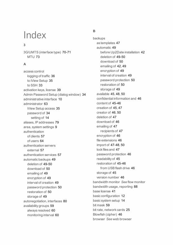
Index3
3G/UMTS (interface type) 70-71MTU 73
A
access controllogging of traffic 36to iView Setup 35to SSH 33
activation keys, license 39Admin Password Setup (dialog window) 34administrative interface 10administrator 63iView Setup access 35password of 34setting of 14
aliases, IP addresses 79area, system settings 9authenticationof clients 57of users 64
authentication serversexternal 57
authentication services 57automatic backups 49deletion of 49-50download of 50emailing of 49encryption of 49interval of creation 49password protection 50restoration of 50storage of 49
autonegotiation, interfaces 80availability groups 59always resolved 60monitoring interval 60
B
backupsas templates 47automatic 49before Up2Date installation 42deletion of 49-50download of 50emailing of 42, 49encryption of 49interval of creation 49password protection 50restoration of 50storage of 49
available 45, 48, 50confidential information and 46content of 45-46creation of 45, 47creator of 46, 50deletion of 47download of 46emailing of 47recipients of 47
encryption of 46file extensions 46import of 47-48, 50lock files and 47password protection 46readability of 45restoration of 45-46fromUSB flash drive 46
storage of 45version number 46
bandwidthmonitor See flow monitorbandwidth usage, reporting 88base license 41basic configuration 12basic system setup 14bit mask 59bit rate, network cards 25Blowfish (cipher) 46browser See web browser

Index
button bar, of iView Setup 17buttons, in iView Setup 22
C
cachefor Up2Dates 44
CBCmode (Cipher BlockChaining) 46CD-ROMdrive, system requirements 8certificate authority 50, 52download of 54import of 53iView Setup certificate 14, 36signing CA 52for VPN 54
verification CA 53certificates 50deletion of 51download of 52generation of 50, 63import of 51information contained in 30invalid 31management of 50of iView Setup 36-37public keys, import of 50revocation lists 50, 54self-signed, of system 13, 50, 53time, time zones, and 36validity of 13, 36VPN ID 51, 63VPN ID type 51X.509 50local 14of users 63
changes, of iView Setup settings 29charts, reporting 83-84client authentication 57command-line access 33,See also shellaccess
company information 14complexity, password 33
configuration 12of Up2Dates 43reset of 34
configuration wizard See wizardconnection types, for Internet uplink 15console See shell accesscontrollersIDE 9SCSI 9
CPU usage 25, 86CPU, system requirements 8CRL See certificates, revocation lists
D
Dashboard 17, 25date 30NTP servers 30, 32setting of 9manual 30, 32
daylight saving time 30definitions 57of networks 57of services 61
detection, hardware 7-8dialog boxes, in iView Setup 21Distinguished Name 50DN See Distinguished NameDNSgroups 59hostname of system and 30hosts 59time-to-live 59
reverse DNS 58dynamic IP endpoints 59
E
email recipientsof backups 42
Ethernet DHCP (interface type) 70, 73MTU 74
Ethernet Static (interface type) 70, 75MTU 76
110 iView Setup 1 Administration Guide

proxyARP 76Ethernet VLAN (interface type) 71, 77MTU 78proxyARP 79
Ethernet, modesof operation 80Excel (format)download of reporting data in 89
external interfaces 15
F
factory reset 34system shutdown 35
file extensionsof backups 46
filter field, of lists 19firmware updates 42download of 43installation of 42-43scheduling of 43
firmware version 25, 42flow monitor 25-26adaption of 73, 75, 77, 79
FQDNhostname and 30
FTPserversof Sophos iView Setup 44
FullyQualified Domain Name See FQDN
G
groupsavailability groups 59DNSgroups 59network groups 59service groups 61-62user groups 65
H
hard diskerasure of 11size and type 8usage of 25
hardwareinterfaces 80minimum requirements 9reporting on 85-87
Hardware Compatibility List 78hardware detection 7-8HCL See Hardware Compatibility ListHDD See hard diskhigh availabilitylinkmonitoring 81takeover 81
homepage, SophosUTM 40hostname, system 36configuration of 30DNSand 30
HTTPSiView Setup CA certificate 14, 36iView Setup certificate 36
I
icons, in iView Setup 22icons, inWebAdminInfo icon 19
IDE controllers 9idle timeout, iView Setup 37Info icon 19interface definitions 70network definitions 57service definitions 61user definitions 63
initial login page 13installation 7abortion of 9and basic configuration 12duration of 11hardware requirements 9key functionsduring 7problemsafter 11system reboot after 11warningmessage 10
installation instructions 7Interface Address 58
iView Setup 1 Administration Guide 111
Index
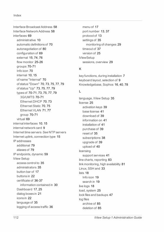
Index
Interface Broadcast Address 58Interface NetworkAddress 58interfaces 69administrative 10automatic definitionsof 70autonegotiation of 80configuration of 69external 15, 74, 76flow monitor 25-26groups 70-71Info icon 70internal 10, 15of name "Internal" 70of status "Down" 70, 73, 75, 77, 79of status "Up" 73, 75, 77, 79typesof 70-71, 73, 75, 77, 793G/UMTS 70-71Ethernet DHCP 70, 73Ethernet Static 70, 75Ethernet VLAN 71, 77group 70-71
virtual 69internal interfaces 10, 15internal network card 9Internet time servers See NTP serversInternet uplink, connection type 15IP addressesadditional 79aliasesof 79
IP endpoints, dynamic 59iView Setupaccess control to 35administrators 35button bar of 17buttons in 22certificate of 36-37information contained in 30
Dashboard 17, 25dialog boxes in 21icons in 22language of 35logging of access traffic 36
menu of 17port number 13, 37protocol of 13settingsof 35monitoring of changes 29
timeout of 37version of 25
iViewSetupsessions, overview 29
K
key functions, during installation 7keyboard layout, selection of 9Knowledgebase, Sophos 16, 40, 78
L
language, iView Setup 35license 25activation keys 39base license 41download of 39information on 41installation of 41purchase of 39reset of 35subscriptions 38upgrade of 39upload of 40
licensingsupport services 41
line charts, reporting 83linkmonitoring, high availability 81Linux, SSH and 33lists 18Info icon 19search in 19
live logs 18load, system 25lock files and backups 47log filesarchive of 85deletion of 85
112 iView Setup 1 Administration Guide

download of 85live log 85of today 84reset of 34search in 84-85view of 84-85
log off 91log partitionhistogram of, utilization 83statusof 83usage of 25
logging 83settingsof 30time gaps 31time settings 30
login pageinitial 13standard 14
login problems 91loginuserpassword of 34
logout 91automatic 91
M
memoryusage of 86
menu, iView Setup 17search box 17
monitoringof link status, high availability 81
MTU3G/UMTS 73Ethernet DHCP 74Ethernet Static 76Ethernet VLAN 78
MyUTMPortal 39-40
N
NAT 80netmask 59network activities 83
network cards 9bit rate 25configuration of 69flow monitor 25-26internal 9name of 25sequence of 11statusof 25SysIDs 74, 76
network definitionsavailability groups 59bind to interface 60creation of 58DNSgroups 59DNShosts 59hosts 58Info icon 57network groups 59typesof 58
network groups 59network interfaces See interfacesnetworkmask See netmasknetwork statisticsoverview of 69
network usage, reporting 87-88networks 57definition of 57static 57
notifications 30NTP servers 30, 32testing of 32
O
object lists 23operating status, system 25organizational information, system 30
P
parent proxiesasUp2Date cache 44-45authentication at 45
iView Setup 1 Administration Guide 113
Index

Index
partition usage 86log partition 86root partition 25, 86storage partition 86
passwordfor shell 33of administrator 15, 34setting of 14
of loginuser 34setting of 33
of root 34setting of 33
of userssetting of 64
ofWebAdmin 15reset of 34-35
password complexity 33pattern updates 42download of 43installation of 42-43
pattern version 25, 43PCI ID 11PDF (format)download of reporting data in 89
PEM (file format) 52pie charts, reporting 84ping check 11availability group 59
PKCS#12 container (file format) 52port numberof iView Setup 13of SSH 34
problems, after installation 11processor 8proxyARP (function)with Ethernet Static 76with Ethernet VLAN 79
proxy server, government-approved See par-ent proxies
R
RAMusage of 25
reboot, systemafter installation 11manual 55
recipientsof emails See email recipients
regular expressions 19reporting 83bandwidth usage 88hardware information 85-87line charts 83network traffic 87-88network usage 87-88pie charts 84settingsof 30time gaps 31time settings 30
reporting datadownload of 89reset of 34
resource usage 25restart, system 55reverse DNS 58revocation lists 50, 54root password 34RSA keysand backups 46
S
SCSI controllers 9search box, of menu 17Secure Shell 33,See also SSHsecurity certificate See certificatessecurity threatsidentification of 83
securitywarning, web browser 13-14, 36self-signed certificateof system 13
114 iView Setup 1 Administration Guide
service definitionschange type of 63creation of 61Info icon of 61
service groups 61-62servicesdefinition of 61using AH 62using ESP 62using ICMP 62using IP 62using TCP 61using UDP 61
sessions, iView Setup, overview of 29shell access 33after password reset 34setting passwords for 33-34
shutdown, system 34, 55after factory reset 35
signing certificate authority 52for VPN 54
Sophos' Portal See MyUTMPortalSophos iView Setup FTP server 44Sophos iView Setup Up2Date Blog 40SophosKnowledgebase 16, 40, 78SophosNSGSupport Forum 16, 40SophosUTMFTP server 44SophosUTM homepage 40SophosUTM portal 39SSH 33access control 33authenticationmethods 33clients 33daemon listen port 34Linuxand 33port number 34public keys 33
standard time 30statistic overviewof network 69
statusof log partition 83
operating, of system 25subnet 10subscriptions, license 38activation of 40information on 41
SuperAdmins (user group) 65support 16Support Forum, SophosNSG 16, 40support services 41swap usage 86symbols See icons, inWebAdminSysIDs, network cards 74, 76systemconfiguration ofreset of 34
organizational information 30reboot ofafter installation 11manual 55
settingsof 12, 29shutdown of 55after factory reset 34-35
system load 25
T
tablesSee also listssorting data 89
tags, VLAN 77takeover, high availability 81templatesbackup templates 47
time 30certificatesand 36daylight saving time 30NTP servers 30, 32setting of 9manual 30, 32
standard time 30time gaps 31
time-to-live 59time zone 30certificatesand 36
iView Setup 1 Administration Guide 115
Index

Index
setting of 9, 32timeout, iView Setup 37toggle switch, inWebAdmin 22trafficmonitor See flow monitorTTL See time-to-live
U
UMTS (interface type) 70-71uninterruptible power supplystatusof 25
Up2Date Blog, Sophos iView Setup 40Up2Date cache 44parent proxies 44-45
Up2Date Information, Sophos iView Setup 40Up2Dates 42configuration of 43connection problems 42digital signature 42download of 42-43installation of 42-43implicit 43
manual upload 44of firmware 42of patterns 43packages, reset of 34scheduling of 43system backup, automatic and 42update servers 42
update servers 42upgrades, of license 39uplink, Internet (connection type) 15UPS See uninterruptible power supplyuser definitions 63administrator privileges 65backend synchronization 64email addressesand 64Info icon 63
users 57, 63authentication of 64certificate of 65currently logged in 18disabling of 64
passwordsetting of 64
user groups 57, 63, 65UTC 31
V
verification certificate authority 53version 25of firmware 25of patterns 25
virtual interfaces 69virtual LAN See VLANVLAN 77tags 77
VPNsigning certificate authority 54
W
warningmessage, at installation 10web browsercertificatesand 13securitywarning 13-14, 36
WebAdminadministrators 15object lists 23password for 15
website, SophosUTM 40wizard 15
X
X.509 certificatesbackupsand 46creation of 50import of 50local 14of users 63
116 iView Setup 1 Administration Guide


![Enterprise Porta1 Transaction Iview[1]](https://img.pdfslide.net/doc/110x75/563dba8f550346aa9aa6ae23/enterprise-porta1-transaction-iview1.jpg)