Embed Size (px)
Citation preview

PRODUCT DATA SHEET
Rev. 04 (EN)
Sormat ITH-GREEN300 ml
ITH
-GRE
EN -
STYR
ENE
FREE
GRE
EN IN
JECT
ION
RES
IN
ORGANISATION CERTIFIED BY
GREEN
Content PageProduct description 2
Properties and benefits 2Sample applications 2Applications and intended use 3Handling and storage 3Curing times 3
Application in concrete 4Installation instructions 4Cleaning 6Installation parameters 6Capacities 7Recommended loads 9
Application in masonry 10Installation instructions 10Cleaning 11Capacities 12Parameters 13
11
Application in non-cracked
concrete
Application in hollow
masonry
Application in solid masonry
Sormat OyHarjutie 5FIN-21290 Rusko, FinlandTelephone +358 (0) 207 940 200Fax +358 (0) 201 76 [email protected]
ITH 300 GREENart. 72962

2
PRODUCT DATA SHEET
Rev. 04 (EN)
Sormat ITH-GREEN300 ml
ITH
-GRE
EN -
STYR
ENE
FREE
GRE
EN IN
JECT
ION
RES
IN
ORGANISATION CERTIFIED BY
GREEN
Product descriptionThe ITH-GREEN - is a 2-component reaction resin mortar, styrene free, and will be delivered in foil tube cartridge system. This product may be used in combination of a hand-, battery-, or pneumatic tool and a static mixer. It was designed as a cost-effective alternative for the anchoring of threaded rods and internal threaded rod sleeves for non-approved applications. By using a sieve sleeve, an easy and safe application in hollow bricks is guaranteed. The ITH-GREEN - product is characterised by good applications with an ambiance temperature up to 80 °C.
Properties and benefits• Application in non-cracked concrete, solid brick and hollow brick with threaded rods• Overhead applications possible• Suitable for attachment points close to the edge, since anchoring is free of
expansion forces • Styrene free• GREEN resin does not contain phtalates• Low VOC content (class A), LEED tested• High bending- and pressure strength• Cartridge can be reused up to the end of the shelf life by replacing the static mixer or
resealing cartridge with the screw cap• Mechanical properties acc. to EN 196 Part 1
+ Density: 1,74 kg/dm2
+ Compressive strength: 75 N/mm2
+ Bending strength: 30 N/mm2
+ Dynamic modulus of elasticity: 4000 N/mm2
+ Shrinkage < 0,4 %
Sample applicationsSuitable for the fixation of facades, roofs, wood construction, metal construction; metal profils, consoles, railings, sanitary devices, cable trays, piping, etc.
22
VOC

3
PRODUCT DATA SHEET
Rev. 04 (EN)
Sormat ITH-GREEN300 ml
ITH
-GRE
EN -
STYR
ENE
FREE
GRE
EN IN
JECT
ION
RES
IN
ORGANISATION CERTIFIED BY
GREEN
Applications and intended use• Base materials:
non-cracked concrete, light-concrete, porous-concrete, solid masonry, hollow brick, natural stone (Attention! natural stone, can discolour; shall be checked in advance); hammer drilled holes
• Anchor elements: Threaded rods (zinc plated or hdg, stainless steel and high corrosion resistant steel), rein-forcement bars, internal threaded rods, profiled rods, steel section with undercuts (e.g. perforated section)
• Temperature range: 5 °C up to +35 °C installation temperaturecartridge temperature min. +5 °C; optimal +20 °C-40 °C to +80 °C base material temperature after full curing
Handling and storage• Storage:
store in a cold and dark place, storage temperature: from +5°C up to +25 °C • Shelf life:
12 months• Expiry date marked on the cartridges
(e.g. 234 SEP17 = September 2017)
Curing timesTemperature of base
materialGelling- and working
timeFull curing time in dry
base materialFull curing time in wet
base material
+35 °C 2 min 20 min 40 min
+30 °C 4 min 25 min 50 min
+20 °C 6 min 45 min 90 min
+10 °C 15 min 80 min 160 min
+5 °C 25 min 120 min 240 min
3

4
PRODUCT DATA SHEET
Rev. 04 (EN)
Sormat ITH-GREEN300 ml
ITH
-GRE
EN -
STYR
ENE
FREE
GRE
EN IN
JECT
ION
RES
IN
ORGANISATION CERTIFIED BY
GREEN
Installation instructions - concrete
1. Drill with hammer drill mode a hole into the base material to the size and embedment depth required by the selected anchor.
or
2a. Standing water must be removed befor cleaning. Starting from the bottom or back of the bore hole, blow the hole clean with compressed air or a hand pump a minimum
of four times. If the bottom of the bore hole is not reached an extension shall be used. The hand-pump can be used for anchor sizes up to bore hole diameter 20 mm. For bore holes larger then 20 mm or deeper then 240 mm, compressed air (min. 6 bar) must be used.
2b. Check brush diameter and brush the hole with an appropriate sized wire brush of four times. If the bottom of the bore hole is not reached with the brush, a brush extension
shall be used.
or
2c.Finally blow the hole clean again with compressed air or a hand pump a minimum of four times. If the bottom of the bore hole is not reached an extension shall be used.
The hand-pump can be used for anchor sizes up to bore hole diameter 20 mm. For bore holes larger then 20 mm or deeper then 240 mm, compressed air (min. 6 bar) must be used.
3. Attach a supplied static-mixing nozzle to the cartridge and load the cartridge into the correct dispensing tool (please note that the cartridge may need to be cut open prior to
attaching the static-mixing nozzle). For every working interruption longer than the recom-mended working time as well as for new cartridges, a new static-mixer shall be used.
4. Prior to inserting the anchor rod into the mortar filled bore hole, the position of the embedment depth shall be marked on the anchor rods.

5
PRODUCT DATA SHEET
Rev. 04 (EN)
Sormat ITH-GREEN300 ml
ITH
-GRE
EN -
STYR
ENE
FREE
GRE
EN IN
JECT
ION
RES
IN
ORGANISATION CERTIFIED BY
GREEN
5. Prior to dispensing into the anchor hole, squeeze out separately a minimum of three full strokes (≥ 10 cm) and discard non-uniformly mixed adhesive components until the
mortar shows a consistent grey colour.
6. Starting from the bottom or back of the cleaned anchor hole fill the hole up to appro-ximately 2/3 with adhesive. Slowly withdraw the static mixing nozzle as the hole fills to
avoid creating air pockets. Observe the gel-/ working times given.
7. Push the threaded rod or reinforcement bar into the anchor hole while turning slightly to ensure positive distribution of the adhesive until the embedment depth is reached.
The anchor should be free of dirt, grease, oil or other foreign material.
8. Be sure that the anchor is fully seated at the bottom of the hole and that excess mortar is visible at the top of the hole. If these requirements are not maintained, the applica-
tion has to be renewed.
9. Allow the adhesive to cure to the specified time prior to applying any load or torque. Do not move or load the anchor until it is fully cured.
10. After full curing, the fixture part can be installed with the max. torque by using a cali-brated torque wrench.
Installation instructions - concrete
6
PRODUCT DATA SHEET
Rev. 04 (EN)
Sormat ITH-GREEN300 ml
ITH
-GRE
EN -
STYR
ENE
FREE
GRE
EN IN
JECT
ION
RES
IN
ORGANISATION CERTIFIED BY
GREEN
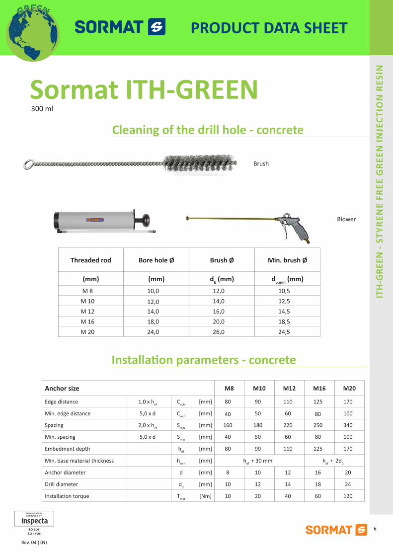
Cleaning of the drill hole - concrete
Brush
Blower
Installation parameters - concrete
Anchor size M8 M10 M12 M16 M20
Edge distance 1,0 x hef Ccr,N [mm] 80 90 110 125 170
Min. edge distance 5,0 x d Cmin [mm] 40 50 60 80 100
Spacing 2,0 x hef Scr,N [mm] 160 180 220 250 340
Min. spacing 5,0 x d Smin [mm] 40 50 60 80 100
Embedment depth hef [mm] 80 90 110 125 170
Min. base material thickness hmin [mm] hef + 30 mm hef + 2d0
Anchor diameter d [mm] 8 10 12 16 20
Drill diameter d0 [mm] 10 12 14 18 24
Installation torque Tinst [Nm] 10 20 40 60 120
Threaded rod Bore hole Ø Brush Ø Min. brush Ø
(mm) (mm) db (mm) db,min (mm)
M 8 10,0 12,0 10,5M 10 12,0 14,0 12,5M 12 14,0 16,0 14,5M 16 18,0 20,0 18,5M 20 24,0 26,0 24,5

7
PRODUCT DATA SHEET
Rev. 04 (EN)
Sormat ITH-GREEN300 ml
ITH
-GRE
EN -
STYR
ENE
FREE
GRE
EN IN
JECT
ION
RES
IN
ORGANISATION CERTIFIED BY
GREEN
Capacities - concreteTENSION LOADS - Design method A acc. to ETAG 001 Annex C, characteristic values for tension loading
Anchor size M8 M10 M12 M16 M20
Steel failure
Characteristic tension resistance, steel, zinc plated or hdg, property class 5.8
NRk,s [kN] 18 29 42 78 122
Characteristic tension resistance, steel, zinc plated or hdg, property class 8.8
NRk,s [kN] 29 46 67 125 196
Partial safety factor γMs,N 1,50
Characteristic tension resistance, stainless steel A4 and HCR
NRk,s [kN] 26 41 59 110 172
Partial safety factor γMs,N 1,87
Pullout and concrete cone failure 1)
Characteristic bond resistance in concrete C20/25
80 °C / 50 °C 2) non-cracked concrete NRk,p =N0Rk,c [kN] 12 18 25 28 47
Partial safety factor(dry and wet) γMp = γMc 1,8
Embedment depth hef [mm] 80 90 110 125 170
Edge distance ccr,N [mm] 80 90 110 125 170
Spacing scr,N [mm] 2 x ccr,N
Increasing factors for non-concrete concrete yc (fck0,30)/2,63
Splitting failureEdge distance ccr,sp [mm] ccr,N ≤ 2 hef (2,5 - h/hef) ≤ 2,4 hef
Spacing scr,sp [mm] 2 x ccr,sp
Partial safety factor(dry and wet)
γMsp 1,8
The data in this table are intended to use together with the design provisions of ETAG 001 Annex C1) Shall be determined acc. this table or acc. to 5.2.2.4, Annex C of ETAG 001. The smaller value is decisive.2) Short term temperature / Long term temperature . Long term concrete temperatures are roughly constant over significant periods of time. Short term elevated temperatures are those that occur over brief intervals, e.g. as a result of diurnal cycling.

8
PRODUCT DATA SHEET
Rev. 04 (EN)
Sormat ITH-GREEN300 ml
ITH
-GRE
EN -
STYR
ENE
FREE
GRE
EN IN
JECT
ION
RES
IN
ORGANISATION CERTIFIED BY
GREEN
Capacities - concreteSHEAR LOADS - Design method A acc. to ETAG 001 Annex C, characteristic values for shear loading
Anchor size M8 M10 M12 M16 M20
Steel failure without lever arm
Characteristic shear resistance, steel, zinc plated or hdg, property class 5.8
VRk,s [kN] 9 15 21 39 61
Characteristic shear resistance, steel, zinc plated or hdg, property class 8.8
VRk,s [kN] 15 23 34 63 98
Partial safety factor γMs,V 1,25
Characteristic shear resistance, stainless steel A4 and HCR
VRk,s [kN] 13 20 30 55 86
Partial safety factor γMs,V 1,56
Steel failure with lever arm
Characteristic bending moment, steel, zinc plated or hdg, property class 5.8
M0Rk,s [Nm] 19 37 65 166 324
Characteristic bending moment, steel, zinc plated or hdg, property class 8.8
M0Rk,s [kN] 30 60 105 266 519
Partial safety factor γMs,V 1,25
Characteristic bending moment, stainless steel A4 and HCR
M0Rk,s [kN] 26 52 92 232 454
Partial safety factor γMs,V 1,56
Concrete pryout failure
Factor k 2,0
Partial safety factor γMcp 1,5
Concrete edge failure
Partial safety factor γMc 1,5
The data in this table is intended to used together with the design provisions of ETAG 001 Annex C.

9
PRODUCT DATA SHEET
Rev. 04 (EN)
Sormat ITH-GREEN300 ml
ITH
-GRE
EN -
STYR
ENE
FREE
GRE
EN IN
JECT
ION
RES
IN
ORGANISATION CERTIFIED BY
GREEN
Recommended loads - concreteThe recommended loads are only valid for single anchor for a roughly design, if the following conditions are valid:dry or wet bore hole, non-cracked concrete C20/25, steel 5.8c ≥ ccr,Ns ≥ scr,Nh ≥ 2 x hef
If the conditions are not fulfilled the loads must be calculated acc. to ETAG 001 Annex C.The safety factors are already included in the recommended loads.
Anchor size M8 M10 M12 M16 M20
Embedment depth hef [mm] 80 90 110 125 170
Edge distance ccr,N [mm] 1,5 x hef
Spacing scr,N [mm] 3,0 x hef
Recommended tension load80 °C / 50 °C 2) NRec [kN] 4,7 7,1 10,0 11,2 18,8
Recommended shear load without lever arm for steel property class 5.8 1) VRec [kN] 5,1 8,6 12,0 22,3 34,9
1) Shear load with lever arm acc. Annex C of ETAG 001. 2) Short term temperature / Long term temperature. Long term concrete temperatures are roughly constant over significant periods of time. Short term elevated temperatures are those that occur over brief intervals, e.g. as a result of diurnal cycling.

10
PRODUCT DATA SHEET
Rev. 04 (EN)
Sormat ITH-GREEN300 ml
ITH
-GRE
EN -
STYR
ENE
FREE
GRE
EN IN
JECT
ION
RES
IN
ORGANISATION CERTIFIED BY
GREEN
Installation instructions - hollow bricks
1. Drill without hammer drill mode a hole into the base material to the size and embed-ment depth required by the selected anchor.
2. In case of a water filled bore hole, the water has to be removed from the hole (e.g. by compressed air or vacuum cleaner). Starting from the bottom or back of the hole, blow
the hole clean with a hand pump a minimum of two times. Then brush the hole with nylon brush a minimum of two times. Finally clean the hole again with a hand pump a minimum of two times.
3. Attach a supplied static-mixing nozzle to the cartridge and load the cartridge into the correct dispensing tool (please note that the cartridge may need to be cut open prior to
attaching the static-mixing nozzle). After every working interruption longer than the recom-mended working time as well as for new cartridges, a new static-mixer shall be used.
4. Prior to inserting the anchor rod into the filled bore hole, the position of the embed-ment depth shall be marked on the anchor rods.
5. Prior to dispensing the mortar into the bore hole, squeeze out separately a minimum of three full strokes (≥ 10 cm) and discard non-uniformly mixed adhesive components until
the mortar shows a consistent grey colour.
6. Insert the perforated sleeve (IOV) into the bore hole. Make sure that the sleeve fits well into the hole. Only use sieves that have the right length.
7. Starting from the back fill the sleeve completely with adhesive. Observe the gel-/ wor-king times.
8. Push the threaded rod or reinforcement bar into the sleeve while turning it slightly to ensure a distribution of the adhesive until the back of the sleeve is reached. The anchor
should be free of dirt, grease, oil or other foreign material.

11
PRODUCT DATA SHEET
Rev. 04 (EN)
Sormat ITH-GREEN300 ml
ITH
-GRE
EN -
STYR
ENE
FREE
GRE
EN IN
JECT
ION
RES
IN
ORGANISATION CERTIFIED BY
GREEN
9. Allow the adhesive to cure to the specified time prior to applying any load to torque. Do not move or load the anchor until it is fully cured.
10. After full curing, the add-on part can be installed with the max. torque by using a cali-brated torque wrench.
Cleaning - masonry
• Brush
• Blower

12
PRODUCT DATA SHEET
Rev. 04 (EN)
Sormat ITH-GREEN300 ml
ITH
-GRE
EN -
STYR
ENE
FREE
GRE
EN IN
JECT
ION
RES
IN
ORGANISATION CERTIFIED BY
GREEN
StoneStrength
class
Standard sleeves IOV 12x50 IOV
16x85IOV
16x135 IOV 20x85
Anchor size M6 / M8 M8 / M10 M12 / M16
Hollow brick
Hlz 4
Frec [kN]
0,3 0,3 0,3 0,3
Hlz 6 0,4 0,4 0,4 0,4
Hlz 12 0,7 0,8 0,8 0,8
Sand -lime hollow brick
KSL 4
Frec [kN]
0,3 0,3 0,3 0,3
KSL 6 0,4 0,4 0,4 0,4
KSL 12 0,7 0,8 0,8 0,8
Sand -lime solid brick 1) KS 12 Frec [kN] 0,5 / 1,7 1,7 1,7 1,7
Solid brick 1) Mz 12 Frec [kN] 0,5 / 1,7 1,7 1,7 1,7
Light concrete hollow brickHbl 2
Frec [kN]0,3 0,3 0,3 0,3
Hbl 4 0,5 0,6 0,6 0,6
Concrete hollow brick Hbn 4 Frec [kN] 0,5 0,6 0,6 0,6
Installation parameters
Spacing plug groupscr,N Group [mm]
Hlz, KSL, MZ, KS = 100Hbl, Hbn = 200
Min. spacing plug group 2) smin Group [mm]Hlz, KSL, MZ, KS = 50
Hbl, Hbn = 200Spacing between single plugs scr,N Single [mm] 250
Edge distance ccr,N [mm] 250
Min. edge distance 3) cmin [mm] 250
with
sle
eve Embedment depth of rod hef [mm] 50 85 135 85
Drilling depth h0 [mm] 55 90 140 90
Min. base material thickness hmin [mm] 110 110 160 110
Drill diameter do [mm] 12 16 20
with
out s
leev
e Embedment depth of rod hef [mm] 60 / 80 80 / 90 90
Drilling depth h0 [mm] 65 / 85 85 / 95 95
Min. base material thickness hmin [mm] 85 / 100 100 / 110 110
Drill diameter do [mm] 8 / 10 10 / 12 14 / 18
Hole diameter in fixture df [mm] 7 / 9 9 / 12 14 / 18
Installation torque Tinst [Nm] 3 / 8 81) Anchoring in masonry of solid lime-sand bricks (KS) and masonry bricks (Mz) does not require perforated sleeve.2) It is permissible to go below the spacing to the minimum value for anchor pairs and groups of four, if the permissible loads are reduced.
The maximum loads must not be exceeded.3) Applies to masonry with top load or proof of tilt. Does not apply to shear loads directed towards a free edge.
Capacities - masonry with standard perforated plastic sieve sleeve IOV

13
PRODUCT DATA SHEET
Rev. 04 (EN)
Sormat ITH-GREEN300 ml
ITH
-GRE
EN -
STYR
ENE
FREE
GRE
EN IN
JECT
ION
RES
IN
ORGANISATION CERTIFIED BY
GREEN
Parameters - masonry with standard perforated plastic sieve sleeve IOV
Permissible load in [kN] for each single brick
Brick format < 4 DF from 4 to 10 DF ≥ 10 DF
Without top load max F [kN] 1,0 1,4 2,0
With top load max F [kN] 1,4 1,7 2,5
Reduced permissible loads with reduced spacing per anchor in anchor groupsscr,N Group ≥ s > smin
Anchor pairs: red F = χs · F recχs = ½ (1 + s/scr,N Group) ≤ 1,0
Groups of four: red F = χs1 · χs2 · F recχs1,2 = ½ (1 + s1,2/scr,N Group) ≤ 1,0
F rec = permissible load per anchorred F = reduced load per anchorscr,N Group = spacings = reduced spacing


![The New Testament in Balangao of the Philippines [blw] - Lukephilippinesforjesus.com/PI_NT_LINKS/blng/luke.pdf146 1 1 Antoyan hen sorat‑o an hea Apo Teofilo. Chuarcha hen tatagu](https://img.pdfslide.net/doc/110x75/5e94ff23b141d16f5714e275/the-new-testament-in-balangao-of-the-philippines-blw-luk-146-1-1-antoyan-hen.jpg)