Embed Size (px)
Citation preview
Sound Generation in the Outlet Section of Gas
Turbine Combustion Chambers
C. Schemel∗ and F. Thiele†
Berlin University of Technology, Hermann–Fottinger–Institute of Fluid Mechanics
and
F. Bake‡, B. Lehmann§ and U. Michel¶
German Aerospace Center, Institute of Propulsion Technology, Turbulence Research Branch
Indirect combustion noise is investigated experimentally and numerically. This noiseis generated in the outlet nozzle of combustion chambers if the entropy of the medium isnonuniform, which is the case in the exhaust of combustors. The contribution to the totalnoise emission of aeroengine combustors is not known. A test rig for the experimental inves-tigation of this noise emission in the presence of swirl is first described. The indirect noiseis generated in an exchangeable convergent–divergent nozzle at the exit of the combustor.The noise radiation is studied in a circular exhaust pipe with probe microphones using a ra-dial mode analysis of the microphone signals. First results of the measured sound fields arereported. The experimental situation will be studied numerically with a 4th order accurateCAA–method, which is first validated with theoretical results of the literature for the casesof a compact nozzle or diffuser and incoming entropy and sound waves in a one–dimensionalmean flow. The agreement with the results of sound generation due to incoming entropywaves and the sound reflection and transmission for incoming sound waves is very good.The method is then applied to the more realistic cases of non–compact nozzles and it isfound that the amplitudes of the generated waves are substantially smaller in comparisonto the one–dimensional theory. The sound generation of real cases like a swirling hot–spotand entropy waves in a one–dimensional flow through a convergent–divergent nozzle as wellas plain entropy waves in the swirl flow of the experimental setup are finally studied andthe noise emission is computed.
Nomenclature
∆l = length of the nozzleγ = ratio of the specific heats
in a gas%′ = density perturbationϕ = angular coordinateω = angular frequencyM = Mach numberRa = Reflection coefficient
R = Radius of the inlet ductTa = Transmission coefficienta = local speed of soundp′ = pressure perturbationr = radial coordinatex = axial coordinate
Subscript
1 = section upstream of thenozzle
2 = section downstream ofthe nozzle
+ = downstream propagating
− = upstream propagating
s = entropy mode wave
∗Research Assistant, Muller–Breslau–Str. 8, 10623 Berlin, Germany, AIAA Student Member†Professor, Muller–Breslau–Str. 8, 10623 Berlin, Germany, AIAA Member‡Research Assistant, Muller–Breslau–Str. 8, 10623 Berlin, Germany§Scientist, Muller–Breslau–Str. 8, 10623 Berlin, Germany¶Senior Scientist, Muller–Breslau–Str. 8, 10623 Berlin, Germany, AIAA Member
1 of 10
American Institute of Aeronautics and Astronautics
I. Introduction
� � � � � � � � � � � � � � � � � � � � � � �� � � � � � � � � � � � � � � � � � � � � � �� � � � � � � � � � � � � � � � � � � � � � �� � � � � � � � � � � � � � � � � � � � � � �
� � � � � � � � � � � � � � � � � � � � � �� � � � � � � � � � � � � � � � � � � � � �� � � � � � � � � � � � � � � � � � � � � �� � � � � � � � � � � � � � � � � � � � � �
� � � � � � � � � � � � � � � � � � � � � � �� � � � � � � � � � � � � � � � � � � � � � �� � � � � � � � � � � � � � � � � � � � � � �
� � � � � � � � � � � � � � � � � � � � � �� � � � � � � � � � � � � � � � � � � � � �� � � � � � � � � � � � � � � � � � � � � �
� � � � � � �� � � � � � �� � � � � � �� � � � � � �
� � � � � � �� � � � � � �� � � � � � �� � � � � � �
− unsteady momentum production− accelerated entropy−wave
Direct noise:
Combustion Zone Propagation Zone(CFD) (CAA)
Jet
ρ’
Indirect noise:− turbulent jet−noise P ~ U
8
Noise from upstream:− direct combustion noise− indirect combustion noise
− hot jet noise P ~ U6
("excess jet noise")
− generation of vorticity
− unsteady entropy productionAdditionally:
Direct noise:− unsteady heat production
− accelerated vorticity−wave ("acoustical Bremsstrahlung")
(hot spots)
(CFD+CAA)
� � �� � �� � �� � �� �
Figure 1. Sources of sound in a combustion chamber with outlet nozzle
Combustion noise has be-come an increasingly impor-tant contribution to aero-engine noise, especially duringthe landing approach of mod-ern aircraft. This experienceis a consequence of the suc-cesses in decreasing jet mix-ing noise and fan noise ofmodern aero-engines. The to-tal noise emitted by a com-bustion chamber consists ofdirect and indirect combus-tion noise. Only the directcombustion noise is related tothe combustion process. Theindirect combustion noise isgenerated when fluid with anonuniform entropy distribu-tion is accelerated in or con-vected through the nozzle lo-cated at the downstream endof the combustion chamber (Fig. 1). The accelerated or decelerated hot spot radiates sound due to a fluctu-ating mass flux. This sound source is fully described by the Computational Aeroacoustic (CAA) approachpresented to address the noise propagation and radiation in the outlet section. In gas turbines, the inletguide vanes for the first turbine stage serve as nozzle for the combustion chamber. The flow in this nozzle ischoked in aero-engines in practically all relevant operating conditions. The relation of indirect combustionnoise to direct combustion noise is not known. This work therefore addresses the indirect combustion noiseand its contribution to the total noise emission of combustion chambers. The basic investigation of theindirect combustion noise is carried out both numerically and experimentally in this work.
II. Model Experiment
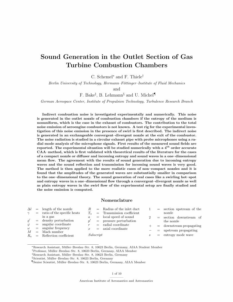
Figure 2. Sketch of the combustion chamber setup usedfor the model experiments.
The setup for the experimental investigation iscarefully chosen to replicate combustion flow char-acteristics of full scale gas turbines while still per-mitting analysis by experimental means. In order tosimplify the numerical approach the system is de-signed axisymmetrical.
A. Setup
The experimental rig consists of a cylindrical modelcombustion chamber made of fused quartz glass. Itis driven by a swirled dual air-flow nozzle in orderto stabilize the combustion zone. Methane gas isintroduced as the fuel between the air streams. Themaximum thermal power is 40 kW. The combustion
2 of 10
American Institute of Aeronautics and Astronautics
chamber is terminated with a convergent–divergent nozzle structure as shown in Fig. 2. The nozzle shape isexchangeable whereby the throat diameters and with it the outlet Mach numbers are variable.
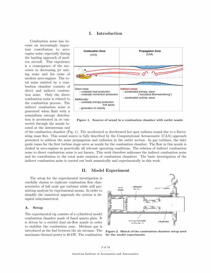
Figure 3. Photo of the perforated end dif-fuser
The nozzle is attached to an exhaust duct with the samediameter as the glass combustion chamber. In order to reducethe impedance jump at the exhaust outlet, an end diffuser isinstalled. In addition, the diffuser, shown in Fig. 3, is perfo-rated with holes of 2 mm diameter with increasing perforationdensity towards the exit. The combustion flow of this facil-ity has been previously investigated under different workingconditions due to intense analyses of mean and instantaneousvelocities and mean temperature.
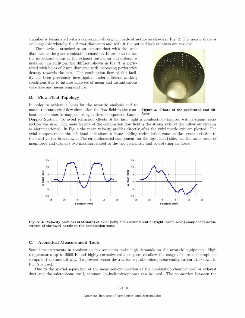
B. Flow Field Topology
In order to achieve a basis for the acoustic analysis and tomatch the numerical flow simulation the flow field in the com-bustion chamber is mapped using a three-component Laser-Doppler-System. To avoid refraction effects of the laser light a combustion chamber with a square crosssection was used. The main feature of the combustion flow field is the strong swirl of the inflow air streamsas aforementioned. In Fig. 4 the mean velocity profiles directly after the swirl nozzle exit are plotted. Theaxial component on the left hand side shows a flame holding recirculation zone on the center axis due tothe swirl vortex breakdown. The circumferential component, on the right hand side, has the same order ofmagnitude and displays two maxima related to the two concentric and co–rotating air flows.
-10
-5
0
5
10
15
-25 -15 -5 5 15 25
z-position [mm]
u-m
ean
[m
/s]
-10
-5
0
5
10
15
-25 -15 -5 5 15 25
z-position [mm]
w-m
ean
[m
/s]
Figure 4. Velocity profiles (LDA-data) of axial (left) and circumferential (right, same scale) component down-stream of the swirl nozzle in the combustion zone.
C. Acoustical Measurement Tools
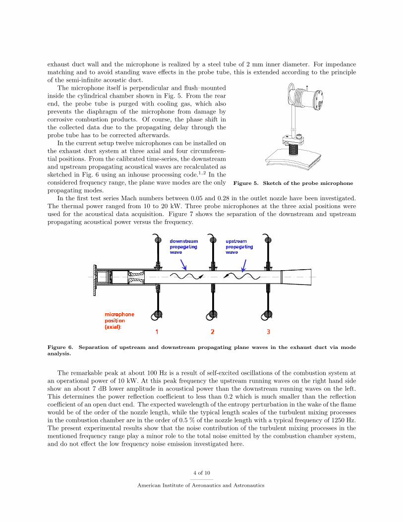
Sound measurements in combustion environments make high demands on the acoustic equipment. Hightemperatures up to 2000 K and highly corrosive exhaust gases disallow the usage of normal microphonesetups in the standard way. To prevent sensor destruction a probe microphone configuration like shown inFig. 5 is used.
Due to the spatial separation of the measurement location at the combustion chamber wall or exhaustduct and the microphone itself, common 1/4-inch-microphones can be used. The connection between the
3 of 10
American Institute of Aeronautics and Astronautics
exhaust duct wall and the microphone is realized by a steel tube of 2 mm inner diameter. For impedancematching and to avoid standing wave effects in the probe tube, this is extended according to the principleof the semi-infinite acoustic duct.
Figure 5. Sketch of the probe microphone
The microphone itself is perpendicular and flush–mountedinside the cylindrical chamber shown in Fig. 5. From the rearend, the probe tube is purged with cooling gas, which alsoprevents the diaphragm of the microphone from damage bycorrosive combustion products. Of course, the phase shift inthe collected data due to the propagating delay through theprobe tube has to be corrected afterwards.
In the current setup twelve microphones can be installed onthe exhaust duct system at three axial and four circumferen-tial positions. From the calibrated time-series, the downstreamand upstream propagating acoustical waves are recalculated assketched in Fig. 6 using an inhouse processing code.1,2 In theconsidered frequency range, the plane wave modes are the onlypropagating modes.
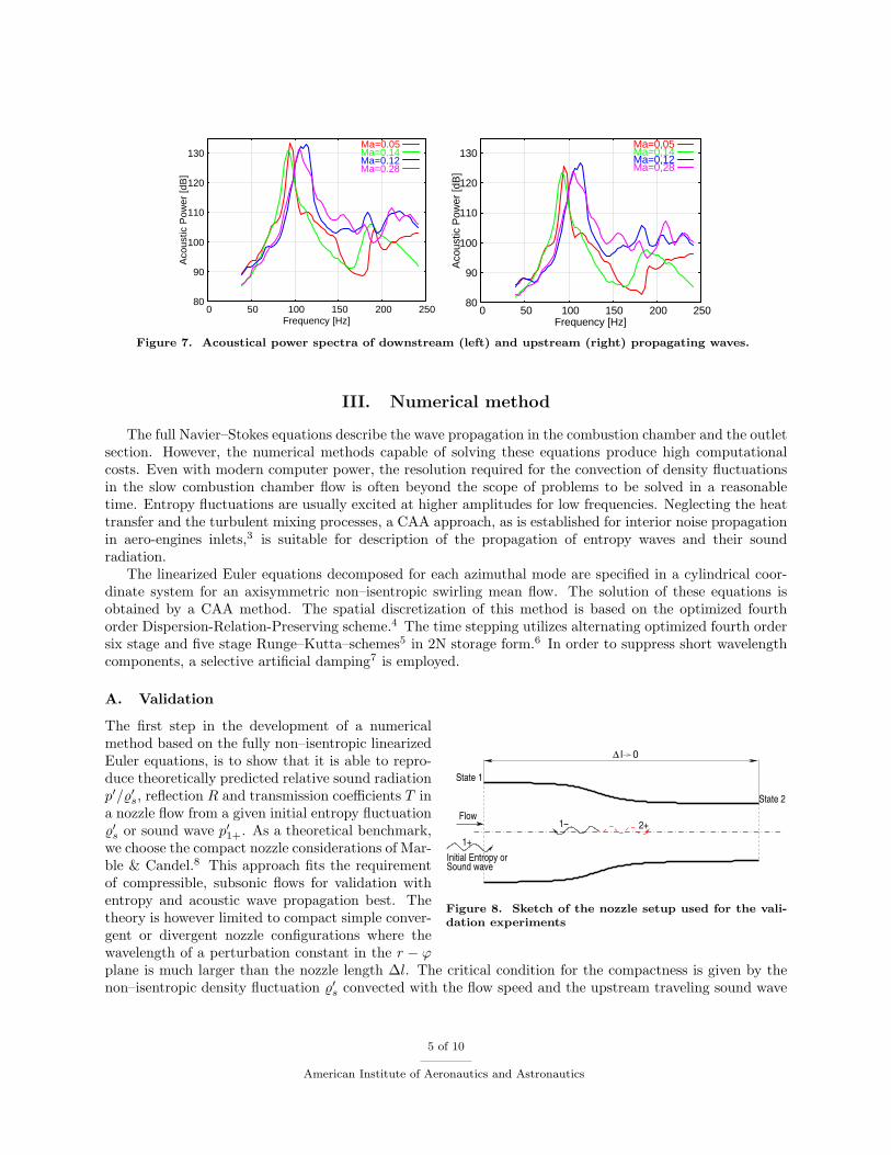
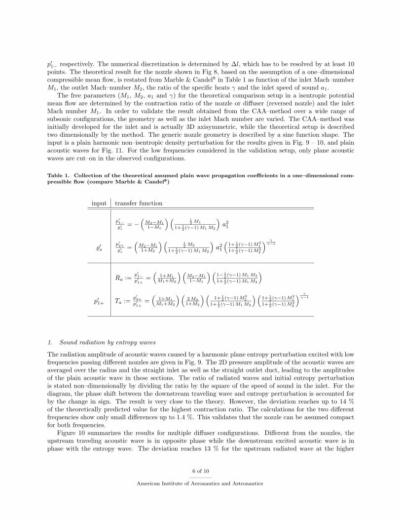
In the first test series Mach numbers between 0.05 and 0.28 in the outlet nozzle have been investigated.The thermal power ranged from 10 to 20 kW. Three probe microphones at the three axial positions wereused for the acoustical data acquisition. Figure 7 shows the separation of the downstream and upstreampropagating acoustical power versus the frequency.
Figure 6. Separation of upstream and downstream propagating plane waves in the exhaust duct via modeanalysis.
The remarkable peak at about 100 Hz is a result of self-excited oscillations of the combustion system atan operational power of 10 kW. At this peak frequency the upstream running waves on the right hand sideshow an about 7 dB lower amplitude in acoustical power than the downstream running waves on the left.This determines the power reflection coefficient to less than 0.2 which is much smaller than the reflectioncoefficient of an open duct end. The expected wavelength of the entropy perturbation in the wake of the flamewould be of the order of the nozzle length, while the typical length scales of the turbulent mixing processesin the combustion chamber are in the order of 0.5 % of the nozzle length with a typical frequency of 1250 Hz.The present experimental results show that the noise contribution of the turbulent mixing processes in thementioned frequency range play a minor role to the total noise emitted by the combustion chamber system,and do not effect the low frequency noise emission investigated here.
4 of 10
American Institute of Aeronautics and Astronautics
80
90
100
110
120
130
0 50 100 150 200 250
Aco
ustic
Pow
er [d
B]
Frequency [Hz]
Ma=0.05Ma=0.14Ma=0.12Ma=0.28
80
90
100
110
120
130
0 50 100 150 200 250
Aco
ustic
Pow
er [d
B]
Frequency [Hz]
Ma=0,05Ma=0,14Ma=0,12Ma=0,28
Figure 7. Acoustical power spectra of downstream (left) and upstream (right) propagating waves.
III. Numerical method
The full Navier–Stokes equations describe the wave propagation in the combustion chamber and the outletsection. However, the numerical methods capable of solving these equations produce high computationalcosts. Even with modern computer power, the resolution required for the convection of density fluctuationsin the slow combustion chamber flow is often beyond the scope of problems to be solved in a reasonabletime. Entropy fluctuations are usually excited at higher amplitudes for low frequencies. Neglecting the heattransfer and the turbulent mixing processes, a CAA approach, as is established for interior noise propagationin aero-engines inlets,3 is suitable for description of the propagation of entropy waves and their soundradiation.
The linearized Euler equations decomposed for each azimuthal mode are specified in a cylindrical coor-dinate system for an axisymmetric non–isentropic swirling mean flow. The solution of these equations isobtained by a CAA method. The spatial discretization of this method is based on the optimized fourthorder Dispersion-Relation-Preserving scheme.4 The time stepping utilizes alternating optimized fourth ordersix stage and five stage Runge–Kutta–schemes5 in 2N storage form.6 In order to suppress short wavelengthcomponents, a selective artificial damping7 is employed.
A. Validation
∆ l 0
1−
1+
State 1
State 2
Sound waveInitial Entropy or
Flow2+
Figure 8. Sketch of the nozzle setup used for the vali-dation experiments
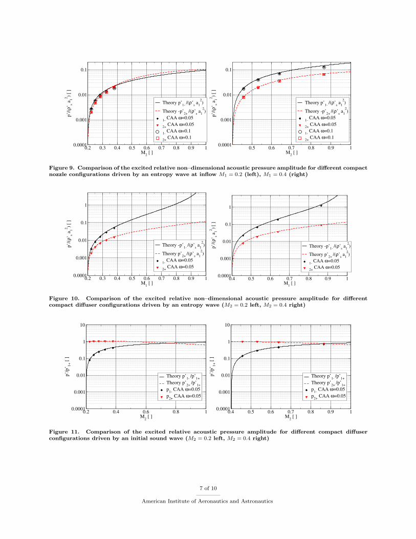
The first step in the development of a numericalmethod based on the fully non–isentropic linearizedEuler equations, is to show that it is able to repro-duce theoretically predicted relative sound radiationp′/%′s, reflection R and transmission coefficients T ina nozzle flow from a given initial entropy fluctuation%′s or sound wave p′1+. As a theoretical benchmark,we choose the compact nozzle considerations of Mar-ble & Candel.8 This approach fits the requirementof compressible, subsonic flows for validation withentropy and acoustic wave propagation best. Thetheory is however limited to compact simple conver-gent or divergent nozzle configurations where thewavelength of a perturbation constant in the r − ϕplane is much larger than the nozzle length ∆l. The critical condition for the compactness is given by thenon–isentropic density fluctuation %′s convected with the flow speed and the upstream traveling sound wave
5 of 10
American Institute of Aeronautics and Astronautics
p′1− respectively. The numerical discretization is determined by ∆l, which has to be resolved by at least 10points. The theoretical result for the nozzle shown in Fig 8, based on the assumption of a one–dimensionalcompressible mean flow, is restated from Marble & Candel8 in Table 1 as function of the inlet Mach–numberM1, the outlet Mach–number M2, the ratio of the specific heats γ and the inlet speed of sound a1.
The free parameters (M1, M2, a1 and γ) for the theoretical comparison setup in a isentropic potentialmean flow are determined by the contraction ratio of the nozzle or diffuser (reversed nozzle) and the inletMach number M1. In order to validate the result obtained from the CAA–method over a wide range ofsubsonic configurations, the geometry as well as the inlet Mach number are varied. The CAA–method wasinitially developed for the inlet and is actually 3D axisymmetric, while the theoretical setup is describedtwo dimensionally by the method. The generic nozzle geometry is described by a sine function shape. Theinput is a plain harmonic non–isentropic density perturbation for the results given in Fig. 9 – 10, and plainacoustic waves for Fig. 11. For the low frequencies considered in the validation setup, only plane acousticwaves are cut–on in the observed configurations.
Table 1. Collection of the theoretical assumed plain wave propagation coefficients in a one–dimensional com-pressible flow (compare Marble & Candel8)
input transfer function
p′1−%′s
= −(
M2−M11−M1
) ( 12 M1
1+ 12 (γ−1) M1 M2
)a21
%′sp′2+%′s
=(
M2−M11+M2
) ( 12 M2
1+ 12 (γ−1) M1 M2
)a21
(1+ 1
2 (γ−1) M21
1+ 12 (γ−1) M2
2
) γγ−1
Ra := p′1−p′1+
=(
1+M1M1+M2
) (M2−M11−M1
) (1− 1
2 (γ−1) M1 M2
1+ 12 (γ−1) M1 M2
)p′1+ Ta := p′2+
p′1+=
(1+M1
M1+M2
) (2 M21+M2
) (1+ 1
2 (γ−1) M22
1+ 12 (γ−1) M1 M2
) (1+ 1
2 (γ−1) M21
1+ 12 (γ−1) M2
2
) γγ−1
1. Sound radiation by entropy waves
The radiation amplitude of acoustic waves caused by a harmonic plane entropy perturbation excited with lowfrequencies passing different nozzles are given in Fig. 9. The 2D pressure amplitude of the acoustic waves areaveraged over the radius and the straight inlet as well as the straight outlet duct, leading to the amplitudesof the plain acoustic wave in these sections. The ratio of radiated waves and initial entropy perturbationis stated non–dimensionally by dividing the ratio by the square of the speed of sound in the inlet. For thediagram, the phase shift between the downstream traveling wave and entropy perturbation is accounted forby the change in sign. The result is very close to the theory. However, the deviation reaches up to 14 %of the theoretically predicted value for the highest contraction ratio. The calculations for the two differentfrequencies show only small differences up to 1.4 %. This validates that the nozzle can be assumed compactfor both frequencies.
Figure 10 summarizes the results for multiple diffuser configurations. Different from the nozzles, theupstream traveling acoustic wave is in opposite phase while the downstream excited acoustic wave is inphase with the entropy wave. The deviation reaches 13 % for the upstream radiated wave at the higher
6 of 10
American Institute of Aeronautics and Astronautics
0.2 0.3 0.4 0.5 0.6 0.7 0.8 0.9 1M2 [ ]
0.0001
0.001
0.01
0.1p’
/(ρ’
s a12 ) [
]
Theory p’1- /(ρ’s a12)
Theory -p’2+ /(ρ’s a12)
1- CAA ω=0.05
2+ CAA ω=0.05
1- CAA ω=0.1
2+ CAA ω=0.1
0.5 0.6 0.7 0.8 0.9 1M2 [ ]
0.0001
0.001
0.01
0.1
p’/(
ρ’s a
12 ) [ ]
Theory p’1- /(ρ’s a12)
Theory -p’2+ /(ρ’s a12)
1- CAA ω=0.05
2+ CAA ω=0.05
1- CAA ω=0.1
2+ CAA ω=0.1
Figure 9. Comparison of the excited relative non–dimensional acoustic pressure amplitude for different compactnozzle configurations driven by an entropy wave at inflow M1 = 0.2 (left), M1 = 0.4 (right)
0.2 0.3 0.4 0.5 0.6 0.7 0.8 0.9 1M1 [ ]
0.0001
0.001
0.01
0.1
1
p’/(
ρ’s a
12 ) [ ]
Theory -p’1- /(ρ’s a12)
Theory p’2+ /(ρ’s a12)
1- CAA ω=0.05
2+ CAA ω=0.05
0.4 0.5 0.6 0.7 0.8 0.9 1M1 [ ]
0.0001
0.001
0.01
0.1
1p’
/(ρ’
s a12 ) [
]
Theory -p’1- /(ρ’s a12)
Theory p’2+ /(ρ’s a12)
1- CAA ω=0.05
2+ CAA ω=0.05
Figure 10. Comparison of the excited relative non–dimensional acoustic pressure amplitude for differentcompact diffuser configurations driven by an entropy wave (M2 = 0.2 left, M2 = 0.4 right)
0.2 0.4 0.6 0.8 1M2 [ ]
0.0001
0.001
0.01
0.1
1
10
p’/p
’ 1+ [
]
Theory p’1- /p’1+Theory p’2+ /p’1+p1- CAA ω=0.05p2+ CAA ω=0.05
0.4 0.5 0.6 0.7 0.8 0.9 1M2 [ ]
0.0001
0.001
0.01
0.1
1
10
p’/p
’ 1+ [
]
Theory p’1- /p’1+Theory p’2+ /p’1+p1- CAA ω=0.05p2+ CAA ω=0.05
Figure 11. Comparison of the excited relative acoustic pressure amplitude for different compact diffuserconfigurations driven by an initial sound wave (M2 = 0.2 left, M2 = 0.4 right)
7 of 10
American Institute of Aeronautics and Astronautics
contracted nozzles.
2. Acoustic wave reflection and transmission
Figure 11 gives an example for the validation on the acoustic wave propagation. In order to model thepropagation of sound waves excited by unsteady combustion, the plain waves are inserted at the upstreamend of the nozzle. Due to the acceleration in the nozzle, the acoustic waves are partly reflected and only afraction of acoustic energy is transmitted downstream through the nozzle. The reflected wave is overpredictedby a maximum of 6 % in the case of Ma = 0.2. The maximum deviation is reached for the highest contractionat Ma = 0.4 with about 6 % underprediction of the pressure amplitude in the inlet duct by the CAA–method.
3. Discussion of the validation
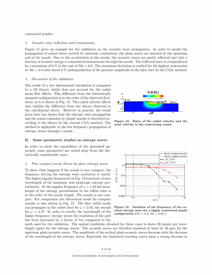
Figure 12. Ratio of the radial velocity and theaxial velocity in the contracting nozzle
The result of a two dimensional calculation is comparedto a 1D theory, which does not account for the radialmean flow effects. This difference from the theoreticallyassumed configuration is in the order of the observed devi-ation, as it is shown in Fig. 12. The radial velocity effectsmay explain the difference from the theory observed inthe calculations above. However in general, the resultgiven here has shown that the entropy wave propagationand the sound radiation by simple nozzles is described ac-cording to the theory by the current CAA–method. Themethod is applicable to the low frequency propagation ofentropy waves through a nozzle.
B. Some parametric studies on entropy waves
0.1 1 10ω [ ]
0.0001
0.001
0.01
0.1
1
p’/(
ρ’s a
12 ) [ ]
theory compact nozzletheory compact nozzle
1-/ρ’s CAA
2+/ρ’s CAA
Figure 13. Variation of the frequency of the ex-cited entropy wave for a highly contracted nozzleconfiguration (M1 = 0.4, M2 = 0.86 )
In order to show the capabilities of the presented ap-proach, some parameters are varied away from the the-oretically considerable cases.
1. Non–compact nozzle driven by plain entropy waves
To show what happens if the nozzle is non–compact, thefrequency driving the entropy wave excitation is varied.The higher angular frequencies in Fig. 13 represent a lowerwavelength of the harmonic non–isentropic entropy per-turbation. At the angular frequency of ω = 1.34 the wave-length of the entropy perturbation in the inflow tube isin the order of the nozzle length. The nozzle is not com-pact. For comparison the theoretical result for compactnozzles is also shown in Fig. 13. The first radial modecan propagate in the outlet duct for ω > 2.44, the secondfor ω > 4.47. In order to resolve the wavelength of thehigher frequency entropy waves the resolution of the gridhas been increased by a factor of ten compared to themesh used for the validation. The spatial resolution obtained for these cases is above 20 points per wave-length (ppw) for the entropy waves. The acoustic waves are therefore resolved at least by 30 ppw for theupstream plain acoustic waves. The amplitude of the excited plain acoustic waves decrease with the decreaseof the wavelength of the entropy waves. Especially the backward traveling waves show a strong decrease in
8 of 10
American Institute of Aeronautics and Astronautics
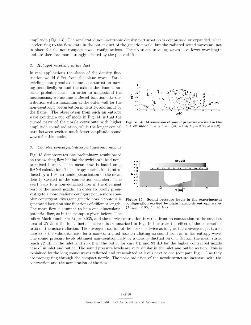
amplitude (Fig. 13). The accelerated non–isentropic density perturbation is compressed or expanded, whenaccelerating to the flow state in the outlet duct of the generic nozzle, but the radiated sound waves are notin phase for the non-compact nozzle configurations. The upstream traveling waves have lower wavelengthand are therefore more strongly effected by the phase shift.
2. Hot spot revolving in the duct
Figure 14. Attenuation of sound pressure excited in thecut–off mode m = 1, n = 1 (M1 = 0.4, M2 = 0.86, ω = 0.2)
In real applications the shape of the density fluc-tuation would differ from the plane wave. For aswirling, non–premixed flame a perturbation mov-ing periodically around the axis of the flame is an-other probable form. In order to understand themechanisms, we assume a Bessel function–like dis-tribution with a maximum at the outer wall for thenon–isentropic perturbation in density, and input bythe flame. The observation from such an entropywave exciting a cut–off mode in Fig. 14, is that thecurved parts of the nozzle contribute with higheramplitude sound radiation, while the longer conicalpart between excites much lower amplitude soundwaves for this mode.
3. Complex convergent–divergent subsonic nozzles
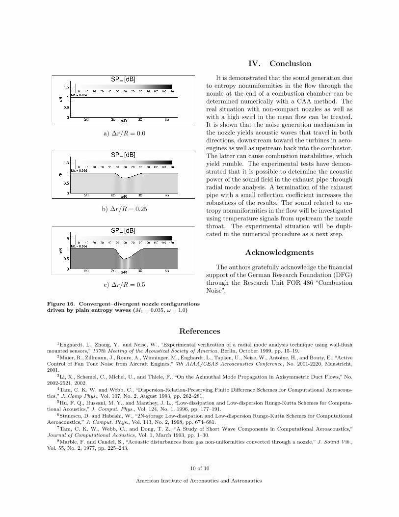
Figure 15. Sound pressure levels in the experimentalconfiguration excited by plain harmonic entropy waves(Mmax = 0.96, f = 90 Hz)
Fig. 15 demonstrates one preliminary result basedon the swirling flow behind the swirl stabilized non–premixed burner. The mean flow is based on aRANS calculation. The entropy fluctuation is intro-duced by a 1 % harmonic perturbation of the meandensity excited in the combustion chamber. Theswirl leads to a non–detached flow in the divergentpart of the model nozzle. In order to briefly prein-vestigate a more realistic configuration, a more com-plex convergent–divergent generic nozzle contour isgenerated based on sine functions of different length.The mean flow is assumed to be a one–dimensionalpotential flow, as in the examples given before. Theinflow Mach number is M1 = 0.035, and the nozzle contraction is varied from no contraction to the smallestarea of 25 % of the inlet duct. The results summarized in Fig. 16 illustrate the effect of the contractionratio on the noise radiation. The divergent section of the nozzle is twice as long as the convergent part, andcase a) is the validation case for a non–contracted nozzle radiating no sound from an initial entropy wave.The sound pressure levels obtained non–isentropically by a density fluctuation of 1 % from the mean state,reach 72 dB in the inlet and 73 dB in the outlet for case b), and 93 dB for the higher contracted nozzlecase c) in inlet and outlet. The sound pressure levels are very similar in the inlet and outlet section. This isexplained by the long sound waves reflected and transmitted at levels next to one (compare Fig. 11) as theyare propagating through the compact nozzle. The noise radiation of the nozzle structure increases with thecontraction and the acceleration of the flow.
9 of 10
American Institute of Aeronautics and Astronautics
IV. Conclusion
a) ∆r/R = 0.0
b) ∆r/R = 0.25
c) ∆r/R = 0.5
Figure 16. Convergent–divergent nozzle configurationsdriven by plain entropy waves (M1 = 0.035, ω = 1.0)
It is demonstrated that the sound generation dueto entropy nonuniformities in the flow through thenozzle at the end of a combustion chamber can bedetermined numerically with a CAA method. Thereal situation with non-compact nozzles as well aswith a high swirl in the mean flow can be treated.It is shown that the noise generation mechanism inthe nozzle yields acoustic waves that travel in bothdirections, downstream toward the turbines in aero-engines as well as upstream back into the combustor.The latter can cause combustion instabilities, whichyield rumble. The experimental tests have demon-strated that it is possible to determine the acousticpower of the sound field in the exhaust pipe throughradial mode analysis. A termination of the exhaustpipe with a small reflection coefficient increases therobustness of the results. The sound related to en-tropy nonuniformities in the flow will be investigatedusing temperature signals from upstream the nozzlethroat. The experimental situation will be dupli-cated in the numerical procedure as a next step.
Acknowledgments
The authors gratefully acknowledge the financialsupport of the German Research Foundation (DFG)through the Research Unit FOR 486 “CombustionNoise”.
References
1Enghardt, L., Zhang, Y., and Neise, W., “Experimental verification of a radial mode analysis technique using wall-flushmounted sensors,” 137th Meeting of the Acoustical Society of America, Berlin, October 1999, pp. 15–19.
2Maier, R., Zillmann, J., Roure, A., Winninger, M., Enghardt, L., Tapken, U., Neise, W., Antoine, H., and Bouty, E., “ActiveControl of Fan Tone Noise from Aircraft Engines,” 7th AIAA/CEAS Aeroacoustics Conference, No. 2001-2220, Maastricht,2001.
3Li, X., Schemel, C., Michel, U., and Thiele, F., “On the Azimuthal Mode Propagation in Axisymmetric Duct Flows,” No.2002-2521, 2002.
4Tam, C. K. W. and Webb, C., “Dispersion-Relation-Preserving Finite Difference Schemes for Computational Aeroacous-tics,” J. Comp Phys., Vol. 107, No. 2, August 1993, pp. 262–281.
5Hu, F. Q., Hussani, M. Y., and Manthey, J. L., “Low-dissipation and Low-dispersion Runge-Kutta Schemes for Computa-tional Acoustics,” J. Comput. Phys., Vol. 124, No. 1, 1996, pp. 177–191.
6Stanescu, D. and Habashi, W., “2N-storage Low-dissipation and Low-dispersion Runge-Kutta Schemes for ComputationalAeroacoustics,” J. Comput. Phys., Vol. 143, No. 2, 1998, pp. 674–681.
7Tam, C. K. W., Webb, C., and Dong, T. Z., “A Study of Short Wave Components in Computational Aeroacoustics,”Journal of Computational Acoustics, Vol. 1, March 1993, pp. 1–30.
8Marble, F. and Candel, S., “Acoustic disturbances from gas non-uniformities convected through a nozzle,” J. Sound Vib.,Vol. 55, No. 2, 1977, pp. 225–243.
10 of 10
American Institute of Aeronautics and Astronautics