Embed Size (px)
Citation preview

BAY AREA AIR QUALITY MANAGEMENT DISTRICT MANUAL OF PROCEDURES VOL IV, SOURCE TEST PROCEDURE ST 34 – BULK AND MARINE LOADING TERMINALS – VAPOR RECOVERY UNITS (Adopted October 7, 1987)(Amended December 7, 2005)
Source Test Procedure ST-34
BULK AND MARINE LOADING TERMINALS VAPOR RECOVERY UNITS (Adopted October 7, 1987)
REF: Regulations 8-33-301, 308, 309, 8-6-302.1 and 8-44-301 1. APPLICABILITY 1.1 This procedure is applicable for quantifying the non-methane organic carbon
(NMOC) emissions from organic compound bulk distribution and marine loading terminals that utilize refrigeration, carbon adsorption, or incineration vapor recovery systems (VRS). It is applicable for the determination of compliance with Regulation 8-33-301, 308, and 309 and Regulation 8-6-302.1, and 8-44-301.
2. PRINCIPLE 2.1 For refrigeration or carbon adsorption units, the exhaust gas volume and
NMOC outlet concentrations are continuously monitored at the VRS outlets. From these parameters, and the total volume of organic liquid loaded, the emission factor of the VRS is determined. In some instances, the exhaust gas volume cannot be accurately measured. Using carbon vessel volume, purge and back flow volume, carbon density, loading information, and inlet and outlet NMOC concentrations, the outlet volumes can be calculated.
2.1.1 A Flame Ionization Detector (FID) may be used for the measurement
of Total Organic Carbon (TOC) provided that the product of the percentages of CO2 and H2O vapor in the gas stream do not exceed 100. In this event, the applicable EPA Reference Method shall be used.
2.2 For incineration units, the TOC concentration and inlet volume to the
incinerator are monitored. The TOC, carbon dioxide, and carbon monoxide concentrations in the exhaust gas are also continuously measured and recorded. From these parameters, and the total volume of organic liquid loaded, the emission factor of the VRS is determined.
2.3 The methane content of the sample shall be determined by either (a) integrated
sampling and GC/FID analysis using EPA Method 18 or BAAQMD Laboratory Method 17 or (b) directing a potion of the conditioned sample through a bed of activated carbon, for NMOC adsorption, prior to the hydrocarbon analyzer.
2.4 The NMOC concentration and exhaust volume from the vapor storage tank
(VST) are continuously monitored and recorded during the test. From these
parameters, the average NMOC concentration and mass emission rate are determined.
2.5 When the volume flow rate over the test duration varies by more than 10% from
the average volume flow rate, the gas constituent average concentrations shall be determined on a flow-weighted basis. Flow-weighted averages shall be determined from data points that are not more than 20 seconds apart. The total mass flow of any given component shall be calculated from that component’s flow-weighted average concentration and the total gas flow. Equations in sections 13, 14 and 15 shall use the flow-weighted averages in place of the applicable average concentration otherwise specified.
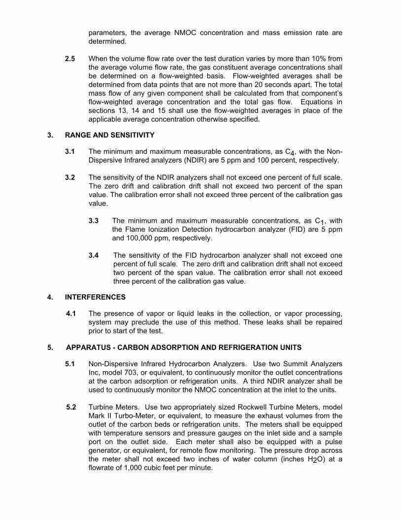
3. RANGE AND SENSITIVITY 3.1 The minimum and maximum measurable concentrations, as C4, with the Non-
Dispersive Infrared analyzers (NDIR) are 5 ppm and 100 percent, respectively. 3.2 The sensitivity of the NDIR analyzers shall not exceed one percent of full scale.
The zero drift and calibration drift shall not exceed two percent of the span value. The calibration error shall not exceed three percent of the calibration gas value.
3.3 The minimum and maximum measurable concentrations, as C1, with
the Flame Ionization Detection hydrocarbon analyzer (FID) are 5 ppm and 100,000 ppm, respectively.
3.4 The sensitivity of the FID hydrocarbon analyzer shall not exceed one
percent of full scale. The zero drift and calibration drift shall not exceed two percent of the span value. The calibration error shall not exceed three percent of the calibration gas value.
4. INTERFERENCES 4.1 The presence of vapor or liquid leaks in the collection, or vapor processing,
system may preclude the use of this method. These leaks shall be repaired prior to start of the test.
5. APPARATUS - CARBON ADSORPTION AND REFRIGERATION UNITS 5.1 Non-Dispersive Infrared Hydrocarbon Analyzers. Use two Summit Analyzers
Inc, model 703, or equivalent, to continuously monitor the outlet concentrations at the carbon adsorption or refrigeration units. A third NDIR analyzer shall be used to continuously monitor the NMOC concentration at the inlet to the units.
5.2 Turbine Meters. Use two appropriately sized Rockwell Turbine Meters, model
Mark II Turbo-Meter, or equivalent, to measure the exhaust volumes from the outlet of the carbon beds or refrigeration units. The meters shall be equipped with temperature sensors and pressure gauges on the inlet side and a sample port on the outlet side. Each meter shall also be equipped with a pulse generator, or equivalent, for remote flow monitoring. The pressure drop across the meter shall not exceed two inches of water column (inches H2O) at a flowrate of 1,000 cubic feet per minute.

5.2.1 Pitot Tube and Pressure Transducer. Some installations preclude the use of turbine meters. In this case, use an appropriately sized pitot tube in conjunction with a pressure transducer, Viatran Corporation Model 219, or equivalent, to determine the velocity heads at the centerline of the outlet duct during the test using BAAQMD Source Test Methods 17 and 18. The output of the transducer shall be continuously recorded on the strip chart recorder. In addition, the transducer/strip chart recorder shall differentiate and record the direction of flow.
Figure 34-1
Zero Air Systems
5.3 Rotary Gas Meter. Use a Roots Meter model 3M125, or equivalent, to
measure the volume of purge air introduced into each carbon bed during the regeneration cycles.
5.4 Strip Chart Recorder. Use a six channel strip chart recorder, or equivalent, to
continuously record the inlet and outlet NMOC concentrations, outlet temperatures, and flowrates from the turbine meters or pitot tube/transducer set-up.
5.5 Sample Pumps. Use leak-free Teflon lined, or equivalent, diaphragm pumps
capable of maintaining a 14.3 liter per minute (0.5 CFM) flowrate at 380 millimeters of mercury (15 inches of mercury).
5.6 Zero-Air System. This system provides nitrogen for zeroing the NDIR
analyzers and is assembled as shown in Figure 34-1.

5.7 Span Gas System. This system delivers appropriate mixtures of span gas, in nitrogen, for the purpose of calibrating the NDIR analyzers during the test. The span gas system is assembled as shown in Figure 34-2.
5.8 Barometer. Use a mercury, aneroid, or other barometer accurate to within 1
millimeter of mercury (0.04 inches of mercury). 5.9 Combustible Gas Detector. Use an explosion-proof Bacharach Instrument
Company model 0023-7356, or equivalent, calibrated with methane. This instrument shall be used to determine the vapor tightness of the collection system and pressure relief valves during the test.
Figure 34-2
NDIR Span Gas System
5.10 Vapor System Pressure Assembly. Use OPW 633-F and 633-D quick connect
couplers, or equivalent, and Dwyer magnehelic gauge 2025, or equivalent, to measure the system pressure. The pressure gauge shall be installed as shown in Figure 34-7.
6. APPARATUS - THERMAL INCINERATION UNITS 6.1 Non-Dispersive Infrared Hydrocarbon Analyzer. Use a Summit Analyzers Inc,
model 703 or equivalent, to continuously monitor the concentration of hydrocarbons in the gas stream at the inlet of the incinerator. A Flame Ionization Detector (FID) may also be used provided that, when necessary, an acceptable dilution apparatus is used.
6.2 Flame Ionization Detector. Use a Beckman, model 400, or equivalent, to continuously monitor the hydrocarbon concentration of the gas stream at the exhaust of the incinerator. The FID shall be calibrated using propane. Appropriate methodology shall be employed to allow the determination of both methane and NMOC concentrations.
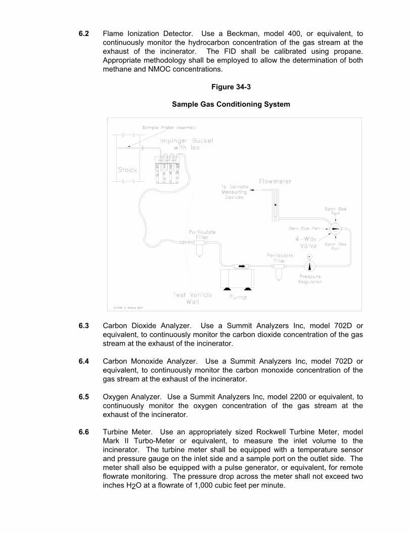
Figure 34-3
Sample Gas Conditioning System
6.3 Carbon Dioxide Analyzer. Use a Summit Analyzers Inc, model 702D or
equivalent, to continuously monitor the carbon dioxide concentration of the gas stream at the exhaust of the incinerator.
6.4 Carbon Monoxide Analyzer. Use a Summit Analyzers Inc, model 702D or
equivalent, to continuously monitor the carbon monoxide concentration of the gas stream at the exhaust of the incinerator.
6.5 Oxygen Analyzer. Use a Summit Analyzers Inc, model 2200 or equivalent, to
continuously monitor the oxygen concentration of the gas stream at the exhaust of the incinerator.
6.6 Turbine Meter. Use an appropriately sized Rockwell Turbine Meter, model
Mark II Turbo-Meter or equivalent, to measure the inlet volume to the incinerator. The turbine meter shall be equipped with a temperature sensor and pressure gauge on the inlet side and a sample port on the outlet side. The meter shall also be equipped with a pulse generator, or equivalent, for remote flowrate monitoring. The pressure drop across the meter shall not exceed two inches H2O at a flowrate of 1,000 cubic feet per minute.

6.6.1 Pitot Tube and Pressure Transducer. Some installations preclude the use of turbine meters. In this case, use an appropriately sized pitot tube in conjunction with a pressure transducer, Viatran Corporation Model 219, or equivalent, to determine the velocity heads at the centerline of the duct during the test using BAAQMD Source Test Methods 17 and 18. The output of the transducer shall be continuously recorded on the strip chart recorder.
Figure 34-4
FID Span Gas System
6.7 Strip Chart Recorder. Use a six channel strip chart recorder, or equivalent, to
continuously record the hydrocarbon concentration and flowrate at the incinerator inlet, and the hydrocarbon, carbon dioxide, carbon monoxide, and oxygen concentrations at the outlet of the incinerator.
6.8 Incinerator Sample Probe Assembly. Use a sample probe assembly as shown
in Figure 34-6. The sample ports in the probe assembly shall be positioned according to the requirements set forth in Source Test Procedure ST-18, Stack Traverse Point Determination.
6.9 Sample Gas Conditioning System. This system removes entrained water from
the sample stream. The sample gas conditioning system is assembled as shown in Figure 34-3.
6.10 Sample Pumps. Use two leak-free Teflon lined, or equivalent, diaphragm
pumps capable of maintaining a 14.3 liter per minute (0.5 CFM) flowrate at 380 millimeters of mercury (15 inches of mercury).

6.11 Zero-Air System. This system provides air or nitrogen for zeroing the FID and
NDIR analyzers, respectively, and is assembled as shown in Figure 34-1.
6.12 FID Span Gas System. This system delivers an appropriate mixture of gaseous propane, in air, for the purpose of calibrating the FID analyzers during the test. The span gas system is assembled as shown in Figure 34-4.
6.13 NDIR Span Gas System. This system delivers an appropriate mixture of
gaseous butane or propane, in nitrogen, for the purpose of calibrating the NDIR analyzers during the test. The span gas system is assembled as shown in Figure 34-2.
6.14 Dry Gas Meter. Use a Rockwell gas meter, model 415 or equivalent, to
measure the auxiliary gas introduced into the incinerator. 6.15 Barometer. Use a mercury, aneroid, or other barometer accurate to within 5
millimeters of mercury (0.2 inches of mercury). 6.16 Combustible Gas Detector. Use an explosion-proof Bacharach Instrument
Company model 0023-7356, or equivalent, calibrated with methane. This instrument shall be used to determine the vapor tightness of the collection system, pressure relief valves, hatches, gauging ports, and miscellaneous vents, during the test.
6.17 Vapor System Pressure Assembly. Use OPW 633-F and 633-D quick connect
couplers, or equivalent, and Dwyer magnehelic gauge 2025, or equivalent, to measure the system pressure. The pressure gauge shall be installed as shown in Figure 34-7.
7. APPARATUS - VAPOR STORAGE TANK (VST) 7.1 Non-Dispersive Infrared Hydrocarbon Analyzers. Use a Summit Analyzers Inc,
model 703, or equivalent, to continuously monitor the outlet concentrations at the main VST vent or manway.
7.2 Turbine Meter/Check Valve Assembly. Use an appropriately sized Rockwell
Turbine Meter, model Mark II Turbo-Meter, or equivalent, to measure the exhaust volume from the main outlet vent or manway of the VST. The meter shall be equipped with a temperature sensor and pressure gauge on the inlet side and a sample port on the outlet side. Each meter shall also be equipped with a pulse generator, or equivalent, for remote flow monitoring. The meter shall be connected to a check valve assembly as shown in Figure 34-5, which allows only the exhaust flow from the VST to be measured by the meter. The maximum pressure drop through the meter/check valve assembly to the atmosphere shall not exceed the cracking pressure setting of the pressure side of the pressure/vacuum valve connected to the head space below the VST bladder. The pressure drop through the check valve to the VST shall not exceed the cracking vacuum setting of the pressure/vacuum valve on the head space above the bladder.

7.3 Strip Chart Recorder. Use a six channel strip chart recorder, or equivalent, to continuously record the outlet NMOC concentration, outlet temperature, and flowrate from the turbine meters.
7.4 Sample Pumps. Use a leak-free Teflon lined, or equivalent, diaphragm pump
capable of maintaining a 14.3 liter per minute (0.5 CFM) flowrate at 380 millimeters of mercury (15 inches of mercury).
Figure 34-5
VST Check Valve Assembly
7.5 Zero-Air System. This system provides nitrogen for zeroing the NDIR analyzer and is assembled as shown in Figure 34-1.
7.6 Span Gas System. This system delivers appropriate mixtures of span gas, in
nitrogen, for the purpose of calibrating the NDIR analyzer during the test. The span gas system is assembled as shown in Figure 34-2.
7.7 Barometer. Use a mercury, aneroid, or other barometer accurate to within 1
millimeter of mercury (0.04 inches of mercury). 7.8 Combustible Gas Detector. Use an explosion-proof Bacharach Instrument
Company model 0023-7356, or equivalent, calibrated with methane. This instrument shall be used to determine the vapor tightness of the collection system and pressure relief valves during the test.
8. PRE-TEST PROCEDURES

8.1 For carbon adsorption and refrigeration units the test equipment shall be set up as recommended by the manufacturer.
8.2 For thermal incineration units the test equipment shall be set up as
recommended by the manufacturer.
8.3 For the Vapor Storage Tank, if equipped, the test equipment shall be set up on the main vent or manway. All other vents shall be temporarily sealed for the duration of the test. If the equipment cannot maintain a pressure drop across the meter/check valve assembly as described in Section 7.2, or if the VST head space is not equipped with a pressure vacuum valve, the Alternative VST Method outlined in Section 11.4 shall be used to determine exhaust flowrates from the VST.
8.4 Zero and span each gas analyzer according to the current instructions provided
by the manufacturer. 8.5 If applicable, zero and span each pressure transducer according to the most
current instructions provided by the manufacturer. 9. SAMPLING - CARBON ADSORPTION AND REFRIGERATION UNITS 9.1 Conduct the test for a minimum of 4 hours or 100,000 gallons throughput,
whichever is greater. Insure the testing interval includes peak loading hours. 9.2 The following data shall be recorded prior to commencement of loading
operations: 9.2.1 The initial readings from the index on each turbine meter. 9.2.2 The initial readings from the product delivery system. 9.2.3 Record the height of the Vapor Storage Tank (VST) if so equipped.
The test shall begin and end at the same VST height. 9.3 During the entire duration of the test the following data acquisition procedures
shall be followed:
9.3.1 Continuously record, on the strip chart recorder, the NMOC concentrations from the NDIR analyzers connected to the turbine meters on the carbon or refrigeration unit outlets.
9.3.2 Continuously record, on the strip chart recorder, the NMOC
concentration at the inlet to the carbon beds or refrigeration units. 9.3.3 Continuously record, on the strip chart recorder, the temperature at
the outlet of the carbon beds or refrigeration units. 9.3.4 Continuously record, on the strip chart recorder, the flowrate through
the turbine meters. If pitot tubes and pressure transducers are used, continuously record the output of the transducers on the strip chart recorder. In addition, flow direction must be differentiated.

9.3.5 Record the barometric pressure, in inches of mercury, at 60 minute intervals during the test.
9.3.6 For carbon adsorption units, record the post-regeneration back flow
volumes through the turbine meters for at least 25 percent of the regeneration cycles during the test.
9.3.7 For carbon adsorption units, record the total number of regeneration
cycles during the test. 9.3.8 For carbon adsorption units, connect the rotary gas meter to the purge
air volume for at least two cycles per bed during the test. 9.3.9 For carbon adsorption units, record the regeneration vacuums, each
minute, for the entire cycle, at least once. 9.3.10 For refrigeration units, record the index readings of the turbine meters
on any units that are in defrost, at least every hour. 9.3.11 Use the combustible gas detector to determine the vapor tightness of
all pressure/vacuum relief valves at least once per hour during the test. Determine the vapor tightness of all hatches, gauge ports, and vents at least twice during the test.
9.4 If outlet flow for carbon adsorption units can not be measured, the following
information must be recorded to use the methodology in Section 13.5. 9.4.1 The initial readings from the product delivery system and purge air
meters. 9.4.2 Continuously record, on the strip chart recorder, the NMOC
concentrations from the NDIR analyzers connected to the carbon bed outlets.
9.4.3 Continuously record, on the strip chart recorder, the NMOC
concentration at the inlet to the carbon beds. 9.4.4 Record the barometric pressure, in inches of mercury, at 60 minute
intervals during the test. 9.4.5 Record the total number of regeneration cycles during the test. 9.4.6 Connect the rotary gas meter to the purge air inlet using 2.5 inch ID
flexible tubing. Record the purge air volume for at least two cycles per bed during the test. In addition, record total purge air for each bed for the entire duration of the test.
9.4.7 For at least two regeneration cycles per carbon bed, record the
regeneration vacuums each minute. 9.4.8 Record the carbon vessel volume and carbon density.

9.4.9 Use the combustible gas detector to determine the vapor tightness of all pressure/vacuum relief valves at least once per hour during the test. Determine the vapor tightness of all hatches, gauge ports, and vents at least twice during the test.
9.5 Use the vapor system pressure assembly to determine the system pressure at
each vapor return arm as follows: 9.5.1 Connect the assembly to vapor coupler of the delivery vehicle.
9.5.2 Zero the pressure gauge according to manufacturer's recommendations.
9.5.3 Connect the vapor return arm to the assembly.
9.5.4 During product loading, record the maximum pressure from the gauge. 10. SAMPLING - THERMAL INCINERATION UNITS 10.1 Conduct the test for a minimum of 4 hours or 100,000 gallons throughput,
whichever is greater. Insure the testing interval includes peak loading hours. 10.2 The following data shall be recorded prior to commencement of loading
operations: 10.2.1 The initial reading from the turbine meter index from the turbine meter
mounted on the incinerator inlet line, if applicable. 10.2.2 The initial readings from the product delivery system. 10.2.3 Record the height of the Vapor Storage Tank (VST) if so equipped.
The test shall begin and end at the same VST height. 10.3 During the entire duration of the test the following data acquisition procedures
shall be followed: 10.3.1 Continuously record, on the strip chart recorder, the inlet hydrocarbon
concentration at the inlet to the incinerator.
Figure 34-6
Incinerator Sample Probe Assembly

10.3.2 Continuously record, on the strip chart recorder, the hydrocarbon, carbon dioxide, carbon monoxide, and oxygen concentrations at the outlet of the incinerator.
10.3.3 Continuously record, on the strip chart recorder, the temperature at
the inlet of the turbine meter. 10.3.4 Continuously record, on the strip chart recorder, the flowrate through
the turbine meter. If pitot tubes and pressure transducers are used, continuously record the output of the transducers on the strip chart recorder.
10.3.5 Record the barometric pressure, in inches of mercury, at 60 minute
intervals during the test. 10.3.6 Determine the methane concentration by either (a) collecting
integrated samples for laboratory analysis or (b) passing a portion of the sample stream through the activated carbon scrubber to adsorb NMOC prior to the analyzer.
10.3.7 Record the auxiliary fuel usage, from the dry gas meter, at 60 minute
intervals during the test. 10.3.8 Use the combustible gas detector to determine the vapor tightness of
all pressure/vacuum relief valves at least once per hour during the test. Determine the vapor tightness of all hatches, gauge ports, and vents at least twice during the test.
10.4 Use the vapor system pressure assembly to determine the system pressure at
each vapor return arm as follows:

10.4.1 Connect the assembly to vapor coupler of the delivery vehicle. 10.4.2 Zero the pressure gauge according to manufacturer's
recommendations. 10.4.3 Connect the vapor return arm to the assembly. 10.4.4 During product loading, record the maximum pressure from the
gauge. 11. SAMPLING - VAPOR STORAGE TANK 11.1 Conduct the test for a minimum of 4 hours or 100,000 gallons throughput,
whichever is greater. Insure the testing interval includes peak loading hours. 11.2 The following data shall be recorded prior to commencement of loading
operations: 11.2.1 The initial readings from the index on the turbine meter. 11.2.2 The initial readings from the product delivery system. 11.2.3 The height of the VST. 11.3 During the entire duration of the test the following data acquisition procedures
shall be followed: 11.3.1 Continuously record, on the strip chart recorder, the NMOC
concentrations from the NDIR analyzer connected to the turbine meter on the main outlet or manway of the VST.
11.3.2 Continuously record, on the strip chart recorder, the temperature at
the outlet of the main vent or manway of the VST. 11.3.3 Continuously record on the strip chart recorder the flowrate through
the turbine meter.
Figure 34-7
Vapor System Pressure Assembly

11.3.4 Record the barometric pressure, in inches of mercury, at 60 minute
intervals during the test. 11.3.5 Record the pressure reading at the meter during out breathing at least
5 times during the test. If the reading exceeds the minimum pressure setting of the pressure/vacuum valve on the head space of the VST, immediately disconnect the meter and reopen any other vents sealed for the test and use the Alternative VST Method to determine the emission rate from the VST.
11.3.6 Record the pressure reading at the check valve during in breathing at
least 5 times during the test. If the reading exceeds the minimum vacuum setting of the pressure/vacuum valve on the head space of the VST, immediately disconnect the meter and reopen any other vents sealed for the test and use the Alternative VST Method to determine the emission rate from the VST.
11.3.7 Use the combustible gas detector to determine the vapor tightness of
all pressure/vacuum relief valves at least once per hour during the test. Determine the vapor tightness of all hatches, gauge ports, vents, and temporarily sealed vents at least twice during the test.
11.4 If the VST is not equipped with a pressure/vacuum valve on the head space
above the bladder or if the pressures at the check valve/meter assembly exceed the pressure/vacuum valve minimum settings the following Alternative VST Method shall be used:
11.4.1 The VST test shall begin when the bladder reaches its lowest possible
point.

11.4.2 The VST shall be isolated from the VRU so that all vapors go directly from the loading rack to the VST.
11.4.3 All valving leading from the VST shall be closed so that all vapors
from the rack remain in the VST. 11.4.4 After each truck finishes loading, the height of the VST shall be
recorded along with the total amount of product loaded. 11.4.5 After the VST has reached 50% of its capacity the valving to the VRU
may be opened and the VST may be returned into normal operation. 11.4.6 A VST height versus product loaded curve shall be generated. 11.4.7 After the VRU/VST equipment is in normal operating mode, the
heights of the VST shall be collected as follows: 11.4.7.1 Each time the bladder begins to raise the height shall be
recorded.
11.4.7.2 Each time the bladder begins to drop the height shall be recorded.
12. POST-TEST PROCEDURES 12.1 At the conclusion of the test the following shall be recorded: 12.1.1 The final turbine meter index reading(s). 12.1.2 The final product meter readings. 12.1.3 The height of the VST, if so equipped. This height shall be the same
as it was at the beginning of the test. 12.2 Record the final dry test meter readings on the auxiliary fuel line for Incineration
Units. 13. CALCULATIONS - CARBON ADSORPTION AND REFRIGERATION UNITS 13.1 The outlet volume from each carbon bed shall be calculated as follows:
( ) ( )
VVT
V NT
Pes
m
m
b
a
b=
+
53029 92.
[Equation 13-1]
where:
Ves = Outlet gas volume from the VRU, standard cubic feet Vm = The uncorrected volume from the turbine meter, actual cubic feet Tm = Average temperature through the turbine meter, oR Vb = The average post regeneration back flow through the turbine meter,
actual cubic feet N = The number of post regeneration back flows during the test

Ta = Average ambient temperature during post-regeneration back flows, oR
Pb = The average barometric pressure during the test, inches of mercury 530 = Standard temperature, oR 29.92 = Standard barometric pressure, inches of mercury
13.1.2 For those tests where a pitot tube and pressure transducer are used
the Carbon Adsorption VRU outlet volume shall be calculated as follows:
( )( )( ) ( )( ) ( )( )( ) ( )
( )( )V t C A pP
T MWep t p AVGs
s
=
. .
.81 60 85 49
53029 92
12
12
∆ [Equation 13-2]
where:
Vep = Outlet gas volume from the VRU, standard cubic feet tt = The total test time, minutes A = The outlet duct cross-sectional area, square feet Cp = The pitot tube coefficient, dimensionless ∆p = The velocity head, inches of water Ts = The average temperature of the outlet gas stream, oR Ps = The absolute stack gas pressure, inches of mercury MW = Average molecular weight of the outlet gas, pound per pound-mole 0.81 = Correction factor for pitot tube at duct centerline, dimensionless 60 = Conversion from seconds to minutes, seconds per minute 85.49 = Conversion Factor derived from Bernoulli's Equation and standard
conditions 530 = Standard temperature, oR 29.92 = Standard barometric pressure, inches of mercury
NOTE: ∆p AVG
12 requires the arithmetic average of the square roots of the
velocity heads. Only outflow shall be used in this calculation. 13.1.3 The outlet volume for refrigeration units shall be calculated as follows:
[ ][ ][ ][ ][ ]V
V V PTrs
m c b
m
=+ 530
29 92. [Equation 13-3]
where:
Vrs = Outlet gas volume from the VRU, standard cubic feet Vm = The uncorrected volume from the turbine meter, actual cubic feet Vc = The uncorrected back flow volume measured during unit defrost,
actual cubic feet Pb = The average barometric pressure during the test, inches of mercury Tm = Average temperature through the turbine meter, oR 530 = Standard temperature, oR 29.92 = Standard barometric pressure, inches of mercury

13.2 The weight of non-methane organic carbon (NMOC) emitted during the test shall be calculated as follows:
[ ][ ][ ][ ][ ]1009.386
MWHCVW esess = [Equation 13-4]
where:
Ws = The weight of NMOC emitted from each carbon bed during the test, pounds
Ves = Outlet gas volume from each carbon bed, using Equation 13-1, 13-2 or 13-3, standard cubic feet
HCes = The average outlet concentration from each carbon bed or refrigeration unit, % NMOC; use flow-weighted average when appropriate.
MW = The molecular weight of the span gas used, pounds per pound-mole 386.9 = The molar volume, cubic feet per pound-mole 100 = The conversion factor from decimal fraction to percent
13.3 For those tests where a turbine meter is used at the inlet to the carbon or
refrigeration unit, the inlet volume shall be calculated as follows:
[ ][ ][ ][ ][ ]92.29T
PP530VVm
sbmis
+= [Equation 13-5]
where:
Vis = Inlet gas volume to the VRU, standard cubic feet Vm = The uncorrected volume from the turbine meter, actual cubic feet Tm = Average temperature through the turbine meter, oR Pb = The average barometric pressure during the test, inches of mercury Ps = The average static pressure at the turbine meter, inches of mercury 530 = Standard temperature, oR 29.92 = Standard barometric pressure, inches of mercury
13.3.1 For those tests where a pitot tube and pressure transducer are used at the inlet to the carbon or refrigeration unit, the inlet volume shall be calculated as follows:
( )( )( ) ( )( ) ( )( )( ) ( )
( )( )V t C A pP
T MWip t p AVGs
s
=
. .
.81 60 85 49
53029 92
12
12
∆ [Equation 13-6]
where:
Vip = Inlet gas volume from the VRU, standard cubic feet tt = The total test time, minutes A = The inlet duct cross-sectional area, square feet Cp = The pitot tube coefficient, dimensionless ∆p = The velocity head, inches of water Ts = The average temperature of the inlet gas stream, oR

Ps = The absolute stack gas pressure, inches of mercury MW = Average molecular weight of the inlet gas, pound per pound-mole 0.81 = Correction factor for pitot tube at duct centerline, dimensionless 60 = Conversion from seconds to minutes, seconds per minute 85.49 = Conversion Factor derived from Bernoulli's Equation and standard
conditions 530 = Standard temperature, oR 29.92 = Standard barometric pressure, inches of mercury
NOTE: ∆p AVG
12 requires the arithmetic average of the square roots of the
velocity heads. 13.3.2 When the inlet volume can not be measured using a turbine meter or
pitot tube, the inlet volume of NMOC entering the carbon adsorption or refrigeration unit during the test shall be calculated as follows:
[ ][ ][ ][ ][ ][ ]V
G P PTis
b m
is
=+530
7 481 29 92. . [Equation 13-7]
where:
Vis = The volume entering the carbon adsorption unit, cubic feet G = The number of gallons of product loaded, gallons Pb = The barometric pressure, inches of mercury Pm = The static inlet line pressure, inches of mercury Tis = The average inlet temperature, oR 530 = Standard temperature, oR 7.481 = The conversion factor from gallons to cubic feet, gallons per cubic foot
13.4 The weight of non-methane organic carbon (NMOC) entering the carbon
adsorption or refrigeration unit during the test shall be calculated as follows:
[ ] [ ] [ ][ ] [ ]1009.386
MWHCVW iisi = [Equation 13-8]
where: Wi = The weight of NMOC entering each carbon or refrigeration unit,
pounds Vis = Inlet gas volume to each carbon bed or refrigeration unit, using
Equation 13-5, 13-6 or 13-7, standard cubic feet HCi = The average inlet concentration from the carbon adsorption or
refrigeration system, % NMOC; use flow-weighted average when appropriate.
MW = The molecular weight of the span gas used, pounds per pound-mole 386.9 = The molar volume, cubic feet per pound-mole 100 = The conversion factor from decimal fraction to percent 13.5 In the event that the outlet flow can not be measured, the following method must
be utilized. The outlet volume from the carbon beds shall be calculated as follows:

V Vregen bedcarbon
carbon
= −
#ρ
[Equation 13-9]
where: Vregen = The regeneration volume of the carbon bed, cubic feet Vbed = The volume of the carbon vessel, cubic feet #carbon = The total amount of carbon in the vessel, pounds ρcarbon = The density of carbon used, pound per cubic foot
( )( ) ( )( )( )( )( ) is
a
b
Oppositepurge
b
regenregenas V
92.29TP530NV
PPV
V1
+
×
+= [Equation 13-10]
where: Vas1
= The outlet volume from Bed 1, cubic feet Pregen = The maximum vacuum reached during regeneration of the
opposite Bed, inches of mercury Vpurge = The average purge air volume, cubic feet Pb = The average barometric pressure, inches of mercury Ta = The average ambient temperature, oR Vis = The total inlet volume, using Equation 13-7, standard cubic feet N = The total number of cycles 530 = Standard temperature, oR
13.5.1 The outlet weight of NMOC for each carbon bed shall be calculated
using Equation 13-4. 13.6 The emission factor for carbon adsorption and refrigeration units shall be
calculated as follows:
[ ][ ] [ ]E
W WGes
es es=
+×1 2 1000 [Equation 13-11]
where: Ees = The total emission factor, pounds per 1,000 gallon loaded Wes1
= The total outlet weight from unit 1 using Equation 13-4, pounds Wes2
= The total outlet weight from unit 2 using Equation 13-4, pounds G = The total number of gallons of product loaded, gallons 13.6.1 The efficiency of the carbon adsorption or refrigeration units shall be
calculated as follows:
[ ][ ] [ ]H
W W WW
i es es
i
=− +
×1 2 100 [Equation 13-12]
where:

H = The efficiency, by weight, of the carbon adsorption unit, percent Wi = The total inlet weight of NMOC using Equations 13-8, pounds Wes1
= The total outlet weight from unit 1, using Equation 13-4, pounds Wes2
= The total outlet weight from unit 2, using Equation 13-4, pounds 100 = The conversion factor from decimal fraction to percent 14. Calculations-Thermal Incineration 14.1 The incinerator inlet volume shall be calculated as follows: 14.1.1 For those tests where a turbine meter is be used the incinerator inlet
volume shall be calculated as follows:
[ ][ ][ ][ ][ ]92.29T
PP530VVm
sbmis
+= [Equation 14-1]
where: Vis = Inlet gas volume to the VRU, standard cubic feet Vm = The uncorrected volume from the turbine meter, actual cubic feet Tm = Average temperature through the turbine meter, oR Pb = The average barometric pressure during the test, inches of mercury Ps = The average static pressure at the turbine meter, inches of mercury 530 = Standard temperature, oR 29.92 = Standard barometric pressure, inches of mercury 14.1.2 For those tests where a pitot tube and pressure transducer are used
the incinerator inlet volume shall be calculated as follows:
( )( )( ) ( )( ) ( )( )( ) ( )
( )( )V t C A pP
T MWip t p AVGs
s
=
. ..
81 60 85 49530
29 92
12
12
∆ [Equation 14-2]
where:
Vip = Inlet gas volume from the VRU, standard cubic feet tt = The total test time, minutes A = The inlet duct cross-sectional area, square feet Cp = The pitot tube coefficient, dimensionless ∆p = The velocity head, inches of water Ts = The average temperature of the inlet gas stream, oR Ps = The absolute stack gas pressure, inches of mercury MW = Average molecular weight of the inlet gas, pound per pound-mole 0.81 = Correction factor for pitot tube at duct centerline, dimensionless 60 = Conversion from seconds to minutes, seconds per minute 85.49 = Conversion Factor derived from Bernoulli's Equation and standard
conditions 530 = Standard temperature, oR 29.92 = Standard barometric pressure, inches of mercury
NOTE: ∆p AVG
12 requires the arithmetic average of the square roots of the
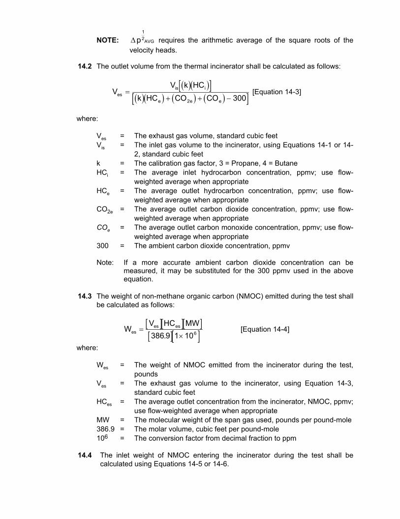
velocity heads. 14.2 The outlet volume from the thermal incinerator shall be calculated as follows:
( )( )[ ]( )( ) ( ) ( )[ ]V
V k HCk HC CO COes
is i
e e e
=+ + −2 300
[Equation 14-3]
where: Ves = The exhaust gas volume, standard cubic feet Vis = The inlet gas volume to the incinerator, using Equations 14-1 or 14-
2, standard cubic feet k = The calibration gas factor, 3 = Propane, 4 = Butane HCi = The average inlet hydrocarbon concentration, ppmv; use flow-
weighted average when appropriate HCe = The average outlet hydrocarbon concentration, ppmv; use flow-
weighted average when appropriate CO2e = The average outlet carbon dioxide concentration, ppmv; use flow-
weighted average when appropriate COe = The average outlet carbon monoxide concentration, ppmv; use flow-
weighted average when appropriate 300 = The ambient carbon dioxide concentration, ppmv Note: If a more accurate ambient carbon dioxide concentration can be
measured, it may be substituted for the 300 ppmv used in the above equation.
14.3 The weight of non-methane organic carbon (NMOC) emitted during the test shall
be calculated as follows:
[ ][ ][ ][ ][ ]WV HC MW
eses es=
×386 9 1 106. [Equation 14-4]
where: Wes = The weight of NMOC emitted from the incinerator during the test,
pounds Ves = The exhaust gas volume to the incinerator, using Equation 14-3,
standard cubic feet HCes = The average outlet concentration from the incinerator, NMOC, ppmv;
use flow-weighted average when appropriate MW = The molecular weight of the span gas used, pounds per pound-mole 386.9 = The molar volume, cubic feet per pound-mole 106 = The conversion factor from decimal fraction to ppm 14.4 The inlet weight of NMOC entering the incinerator during the test shall be
calculated using Equations 14-5 or 14-6.

14.4.1 If actual inlet flow measurements cannot be obtained, the inlet weight shall be calculated as follows:
[ ][ ][ ][ ][ ][ ][ ][ ]
[ ][ ][ ][ ][ ][ ][ ]W
G HC MWT
V HC MWTis
is
is
aux ai
ai
= +530
7 481 386 9 100530
386 9 100. . . [Equation 14-5]
where: Wis = The weight of NMOC entering the carbon adsorption unit, pounds G = The number of gallons of product loaded, gallons HCis = The average inlet concentration, % NMOC; use flow-weighted
average when appropriate Tis = The average inlet gas stream temperature, oR Vaux = The volume of auxiliary gas introduced before the incinerator, cubic
feet HCai = The average auxiliary gas concentration, % Tai = The average auxiliary gas temperature, oR MW = The molecular weight of the span gas used, pounds per pound-mole 530 = Standard temperature, oR 7.481 = The conversion factor from gallons to cubic feet, gallons per cubic
foot 386.9 = The molar volume, cubic feet per pound-mole 100 = The conversion factor from decimal fraction to percent 14.4.2 If a pitot tube and pressure transducer or a turbine meter was used, the
inlet weight shall be calculated as follows:
[ ][ ][ ][ ][ ]W
V HC MWip
ip is=386 9 100.
[Equation 14-6]
where: Wip = The weight of NMOC entering the VRU, pounds Vip = Inlet gas volume calculated using Equations 14-1 or 14-2, standard
cubic feet HCis = The average inlet concentration, % NMOC; use flow-weighted
average when appropriate MW = The molecular weight of the span gas used, pounds per pound-mole 386.9 = The molar volume, cubic feet per pound-mole 100 = The conversion factor from decimal fraction to percent 14.5 The emission factor for the incinerator shall be calculated as follows:
[ ][ ] [ ]EWGes
es= × 1000 [Equation 14-7]
where:

Ees = The total emission factor, pounds per 1,000 gallons loaded Wes = The total outlet weight during the test, using Equation 14-4, pounds G = The total number of barrels of product loaded, gallons 14.6 The efficiency of the incinerator shall be calculated as follows:
[ ] [ ][ ] [ ]H
W WW
i es
i
=−
× 100 [Equation 14-8]
where: H = The efficiency, by weight, of the incinerator, percent Wi = The total inlet weight using Equations 14-5 or 14-6, pounds Wes = The total outlet weight using Equation 14-4, pounds 100 = The conversion factor from decimal fraction to percent 15. Calculations - Vapor Storage Tank 15.1 The outlet volume from the VST shall be calculated as follows:
[ ][ ][ ][ ][ ]92.29T
PP530VVm
sbmis
+= [Equation 15-1]
where: Vot = The outlet gas volume from the VST, standard cubic feet Vm = The uncorrected volume from the turbine meter, actual cubic feet Tm = Average temperature through the turbine meter, oR Pb = The average barometric pressure during the test, inches of mercury Ps = The average static pressure at the turbine meter, inches of mercury 530 = Standard temperature, oR 29.92 = Standard barometric pressure, inches of mercury 15.2 The weight of non-methane organic carbon (NMOC) emitted during the test shall
be calculated as follows:
[ ][ ][ ][ ][ ]WV HC MW
otot ot=
×386 9 1 10 6. [Equation 15-2]
where: Wot = The weight of NMOC emitted from the VST during the test, pounds Vot = The exhaust gas volume from the VST, using Equation 15-1,
standard cubic feet HCot = The average outlet concentration from the VST, NMOC, ppmv; use
flow-weighted average when appropriate MW = The molecular weight of the span gas used, pounds per pound-mole 386.9 = The molar volume, cubic feet per pound-mole 106 = The conversion factor from decimal fraction to ppm

15.3 The daily emissions from the VST shall be calculated as follows:
[ ][ ][ ]E
Wtot
ot
time
=1440
[Equation 15-3]
where: Eot = The emissions from the VST, pounds per day Wot = Weight of hydrocarbon emitted, using Equation 15-2, pounds ttime = The total time the test was conducted, minutes 1440 = The conversion factor from minutes to day, minutes per day 15.4. If the Alternative Method from Section 11.4 is used, the emission from the VST
shall be calculated as follows: 15.4.1 For each rise in the VST the total increase in height shall be
calculated. 15.4.2 Using the loading versus tank height curve, each tank height increase
shall be converted to gallons displaced from the head space above the bladder.
15.4.3 Total all gallons displaced, from Section 15.4.2, for the entire test. 15.4.4 The total weight of NMOC emitted from the VST shall be calculated as
follows:
[ ][ ][ ][ ][ ][ ][ ][ ][ ][ ]
WG HC MW P
Totdis ot b
a
=×
5307 481 386 9 1 10 29 926. . .
[Equation 15-4]
where: Wot = The weight of NMOC emitted from the VST during the test, pounds Gdis = The total gallons displaced by the bladder from Section 15.4.3,
gallons HCot = The average outlet concentration from the VST, NMOC, ppmv; use
flow-weighted average when appropriate MW = The molecular weight of the span gas used, pounds per pound-mole Pb = The average barometric pressure during the test, inches of mercury Ta = The average ambient temperature during the test, oR 7.481 = The conversion from gallons to cubic feet, gallons per cubic foot 386.9 = The molar constant, cubic feet per pound-mole 106 = The conversion factor from decimal fraction to ppm 29.92 = Standard barometric pressure, inches of mercury 16. Reporting 16.1 The results of a test on a carbon adsorption unit shall be reported as shown in
Form 34-1. The results of a test on a refrigeration unit shall be reported as shown in Form 34-2. The results of a test on a thermal incineration unit shall be reported as shown in Form 34-3. The results of a test on a vapor storage tank shall be reported as shown in Form 34-4.

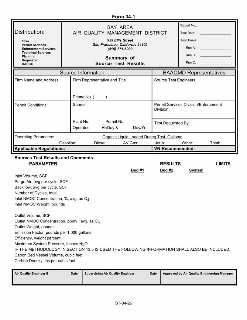
Form 34-1
ST-34-26
Distribution: Firm
Permit Services Enforcement Services Technical Services Planning Requester DAPCO
BAY AREA AIR QUALITY MANAGEMENT DISTRICT
939 Ellis Street San Francisco, California 94109
(415) 771-6000
Summary of Source Test Results
Report No.: Test Date: Test Times: Run A: Run B: Run C:
Source Information BAAQMD Representatives Firm Name and Address
Firm Representative and Title
Phone No. ( )
Source Test Engineers
Permit Conditions: Source:
Permit Services Division/Enforcement Division
Plant No. Permit No. Test Requested By: Operates Hr/Day & Day/Yr
Operating Parameters: Organic Liquid Loaded During Test, Gallons: Gasoline: Diesel: AV Gas: Jet A: Other: Total: Applicable Regulations: VN Recommended:
Sources Test Results and Comments: PARAMETER RESULTS LIMITS Bed #1 Bed #2 System Inlet Volume, SCF Purge Air, avg per cycle, SCF Backflow, avg per cycle, SCF Number of Cycles, total Inlet NMOC Concentration, %, avg. as C4 Inlet NMOC Weight, pounds Outlet Volume, SCF Outlet NMOC Concentration, ppmv , avg. as C4 Outlet Weight, pounds Emission Factor, pounds per 1,000 gallons Efficiency, weight percent Maximum System Pressure, Inches H2O IF THE METHODOLOGY IN SECTION 13.5 IS USED THE FOLLOWING INFORMATION SHALL ALSO BE INCLUDED: Cabon Bed Vessel Volume, cubic feet Carbon Density, lbs per cubic foot Air Quality Engineer II Date
Supervising Air Quality Engineer Date
Approved by Air Quality Engineering Manager
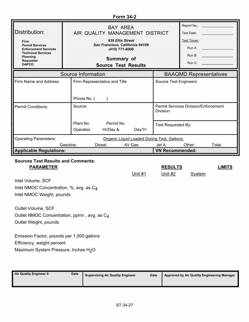
Form 34-2
ST-34-27
Distribution: Firm
Permit Services Enforcement Services Technical Services Planning Requester DAPCO
BAY AREA AIR QUALITY MANAGEMENT DISTRICT
939 Ellis Street San Francisco, California 94109
(415) 771-6000
Summary of Source Test Results
Report No.: Test Date: Test Times: Run A: Run B: Run C:
Source Information BAAQMD Representatives Firm Name and Address
Firm Representative and Title
Phone No. ( )
Source Test Engineers
Permit Conditions: Source:
Permit Services Division/Enforcement Division
Plant No. Permit No. Test Requested By: Operates Hr/Day & Day/Yr
Operating Parameters: Organic Liquid Loaded During Test, Gallons: Gasoline: Diesel: AV Gas: Jet A: Other: Total: Applicable Regulations: VN Recommended:
Sources Test Results and Comments: PARAMETER RESULTS LIMITS Unit #1 Unit #2 System Inlet Volume, SCF Inlet NMOC Concentration, %, avg. as C4 Inlet NMOC Weight, pounds Outlet Volume, SCF Outlet NMOC Concentration, ppmv , avg. as C4 Outlet Weight, pounds Emission Factor, pounds per 1,000 gallons Efficiency, weight percent Maximum System Pressure, Inches H2O Air Quality Engineer II Date
Supervising Air Quality Engineer Date
Approved by Air Quality Engineering Manager

Form 34-3
ST-34-28
Distribution: Firm
Permit Services Enforcement Services Technical Services Planning Requester DAPCO
BAY AREA AIR QUALITY MANAGEMENT DISTRICT
939 Ellis Street San Francisco, California 94109
(415) 771-6000
Summary of Source Test Results
Report No.: Test Date: Test Times: Run A: Run B: Run C:
Source Information BAAQMD Representatives Firm Name and Address
Firm Representative and Title
Phone No. ( )
Source Test Engineers
Permit Conditions: Source:
Permit Services Division/Enforcement Division
Plant No. Permit No. Test Requested By: Operates Hr/Day & Day/Yr
Operating Parameters: Organic Liquid Loaded During Test, Gallons: Gasoline: Diesel: AV Gas: Jet A: Other: Total: Applicable Regulations: VN Recommended:
Sources Test Results and Comments: PARAMETER RESULTS LIMITS Inlet Volume to Incinerator, SCF Inlet Volume, Auxiliary Fuel, SCF Inlet NMOC Concentration, %, avg. as C4 Inlet NMOC Weight, pounds Outlet Hydrocarbon Concentration, ppmv , avg. as C3 Outlet Methane Concentration, ppmv, avg. as C1 Outlet CO Concentration, ppmv, avg. Outlet CO2 Concentration, %, avg. Outlet Volume, SCF NMOC as C3 CO CO2 Outlet Weight, pounds Emission Factor, pounds per 1,000 gallons Efficiency, weight percent Maximum System Pressure, Inches H2O Air Quality Engineer II Date
Supervising Air Quality Engineer Date
Approved by Air Quality Engineering Manager

Form 34-4
ST-34-29
Distribution: Firm
Permit Services Enforcement Services Technical Services Planning Requester DAPCO
BAY AREA AIR QUALITY MANAGEMENT DISTRICT
939 Ellis Street San Francisco, California 94109
(415) 771-6000
Summary of Source Test Results
Report No.: Test Date: Test Times: Run A: Run B: Run C:
Source Information BAAQMD Representatives Firm Name and Address
Firm Representative and Title
Phone No. ( )
Source Test Engineers
Permit Conditions: Source:
Permit Services Division/Enforcement Division
Plant No. Permit No. Test Requested By: Operates Hr/Day & Day/Yr
Operating Parameters: Organic Liquid Loaded During Test, Gallons: Gasoline: Diesel: AV Gas: Jet A: Other: Total: Applicable Regulations: VN Recommended:
Sources Test Results and Comments: PARAMETER RESULTS LIMITS VST Outlet Volume, SCF VST Outlet NMOC Concentration, ppmv, avg. as C1 VST Test Time, total minutes VST Outlet NMOC Weight, pounds VST Emission Factor, pounds per day Air Quality Engineer II Date
Supervising Air Quality Engineer Date
Approved by Air Quality Engineering Manager