Embed Size (px)
Citation preview
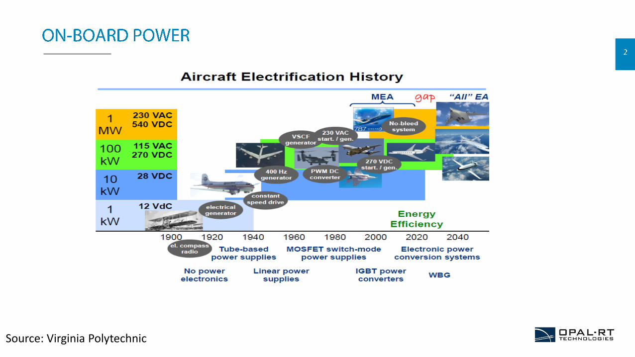
Source: Virginia Polytechnic
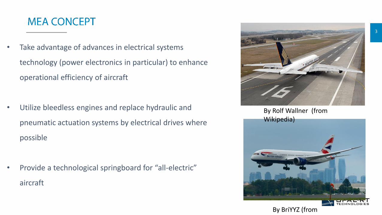
• Take advantage of advances in electrical systems
technology (power electronics in particular) to enhance
operational efficiency of aircraft
• Utilize bleedless engines and replace hydraulic and
pneumatic actuation systems by electrical drives where
possible
• Provide a technological springboard for “all-electric”
aircraft
By Rolf Wallner (from Wikipedia)
By BriYYZ (from Wikipedia/Flickr)
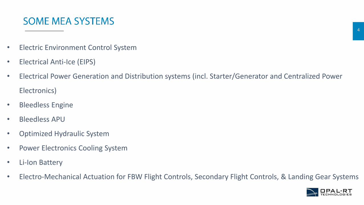
• Electric Environment Control System
• Electrical Anti-Ice (EIPS)
• Electrical Power Generation and Distribution systems (incl. Starter/Generator and Centralized Power
Electronics)
• Bleedless Engine
• Bleedless APU
• Optimized Hydraulic System
• Power Electronics Cooling System
• Li-Ion Battery
• Electro-Mechanical Actuation for FBW Flight Controls, Secondary Flight Controls, & Landing Gear Systems
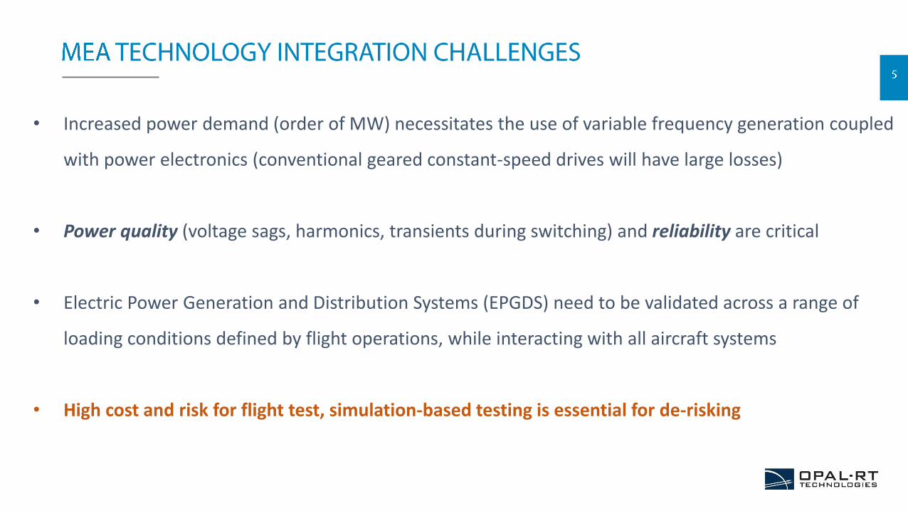
• Increased power demand (order of MW) necessitates the use of variable frequency generation coupled
with power electronics (conventional geared constant-speed drives will have large losses)
• Power quality (voltage sags, harmonics, transients during switching) and reliability are critical
• Electric Power Generation and Distribution Systems (EPGDS) need to be validated across a range of
loading conditions defined by flight operations, while interacting with all aircraft systems
• High cost and risk for flight test, simulation-based testing is essential for de-risking
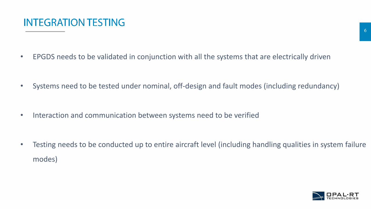
• EPGDS needs to be validated in conjunction with all the systems that are electrically driven
• Systems need to be tested under nominal, off-design and fault modes (including redundancy)
• Interaction and communication between systems need to be verified
• Testing needs to be conducted up to entire aircraft level (including handling qualities in system failure
modes)
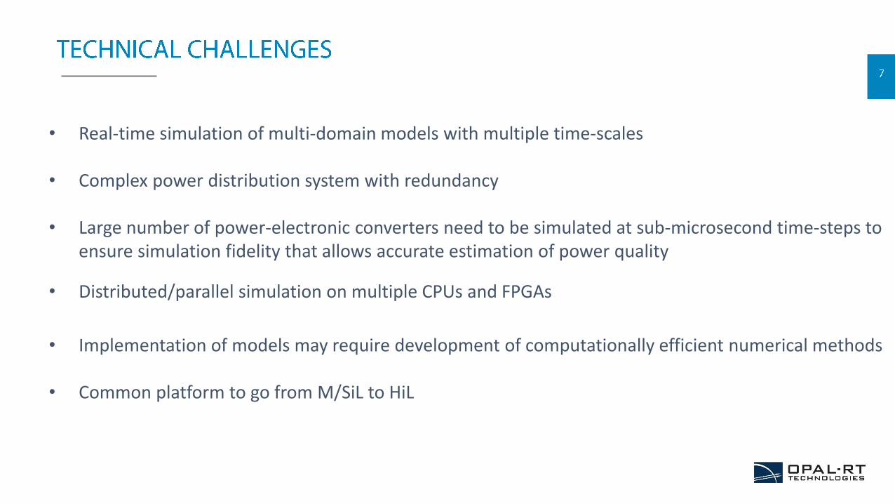
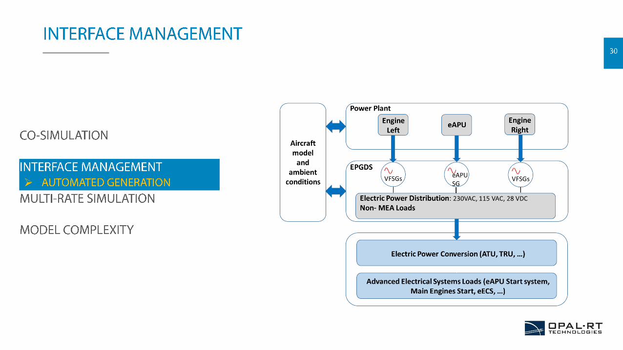
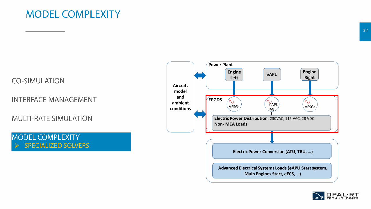
• Real-time simulation of multi-domain models with multiple time-scales
• Complex power distribution system with redundancy
• Large number of power-electronic converters need to be simulated at sub-microsecond time-steps to ensure simulation fidelity that allows accurate estimation of power quality
• Distributed/parallel simulation on multiple CPUs and FPGAs
• Implementation of models may require development of computationally efficient numerical methods
• Common platform to go from M/SiL to HiL
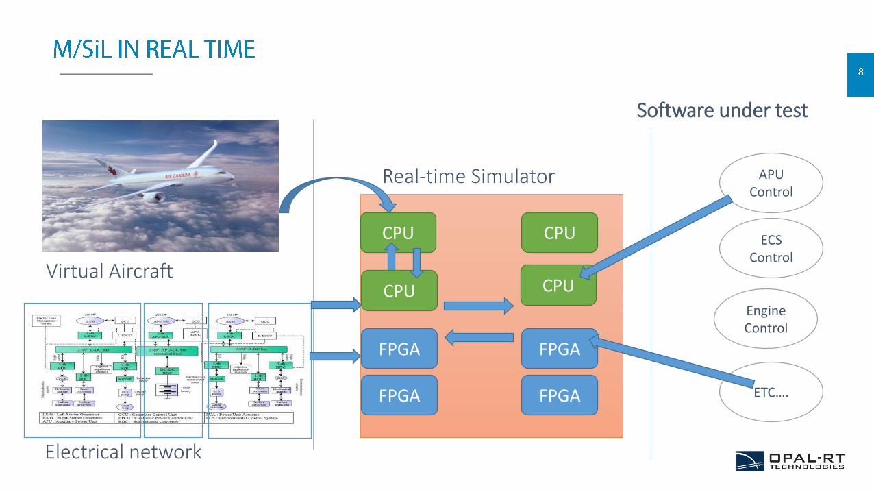
Electrical network
Virtual Aircraft
FPGA FPGA
FPGA FPGA
CPU
Real-time Simulator APU Control
Software under test
ECS Control
Engine Control
ETC….
CPU
CPU
CPU
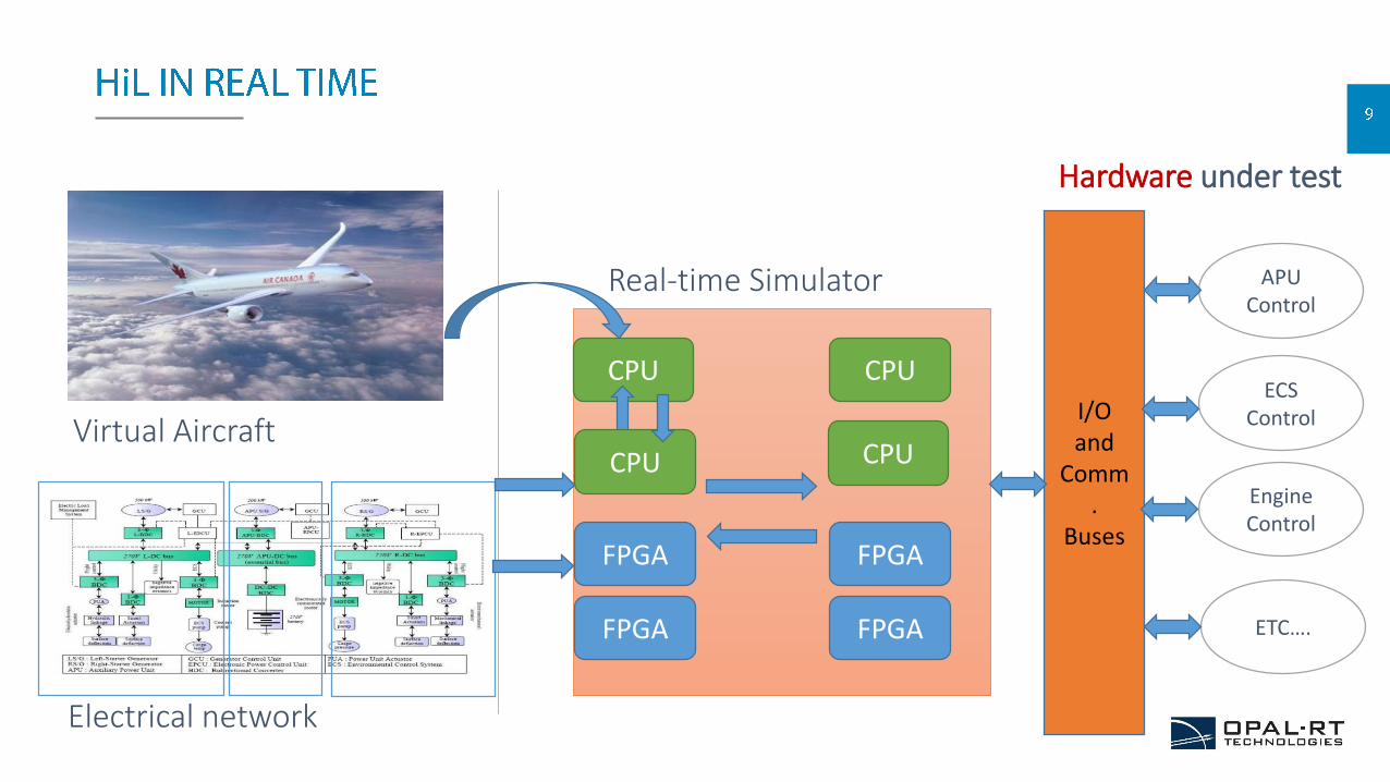
Electrical network
Virtual Aircraft
FPGA FPGA
FPGA FPGA
CPU
Real-time Simulator APU Control
Hardware under test
ECS Control
Engine Control
ETC….
CPU
CPU
CPU
I/O and
Comm.
Buses
Throttle_R
20
Hagl_m
19
Mext
18
Zext
17
Rudder
16
Aileron
15
Elevator
14
Psi
13
Theta
12
Phi
11
Altitude_ft
10
Mach
9
Climb
8
Thrust
7
DeltaThrottle
6
Nz
5
Ny
4
Track
3
Beta
2
Gamma
1
KIAS
TP
Target_Points
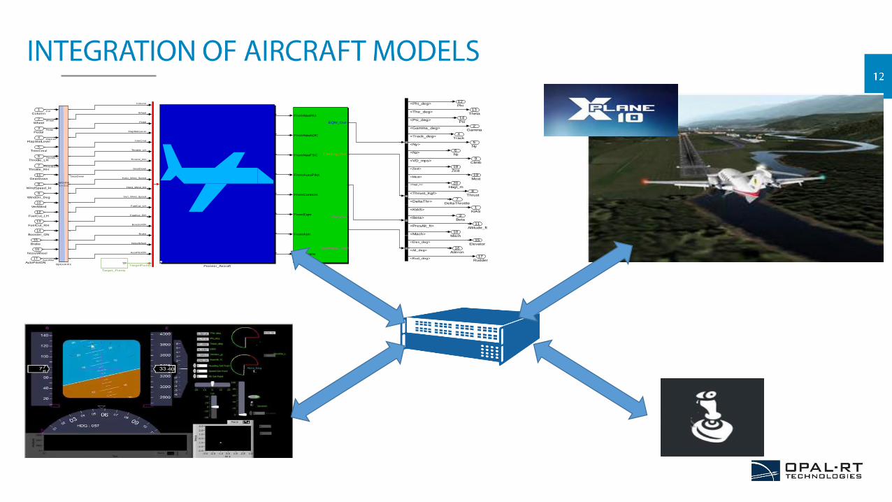
Pioneer_Aircraft
FromNavlRU
FromNavADC
FromNavFSC
FromAutoPilot
FromControls
FromEqm
FromAtm
FromEngine
EQM_Out
TJetEng_Out
Atm_Out
Ctrl_Out
OpXPlane_out
Outputs
OpComm
Ts = 0.01
OpComm1
17
AutoPilotON
16
NoseWheel
15
Brake
14
Booster_ON
13
FuelCut_RH
12
FuelCut_LH
11
GearDown
10
VertWind
9
WindDir_Deg
8
WindSpeed_kt
7
Throttle_RH
6
Throttle_LH
5
TrimCmd
4
FlapSlatLever
3
Pedal
2
Wheel
1
Column
<VD_mps>
<Phi_deg>
<The_deg>
<Psi_deg>
<Gamma_deg>
<Track_deg>
<Ny>
<Nz>
<DeltaThr>
<KIAS>
<Beta>
<PresAlt_ft>
<Mach>
<Thrust_Kgf>
<Elev_deg>
<Ail_deg>
<Rud_deg>
<Zext>
<Mext>
<Hagl_m>
Col
Wheel
Pedal
FlapLev
Throttle_L
TargetPoints
Column
Wheel
Pedal
FlapSlatLev er
TrimCmd
Throttle_LH
Throttle_RH
GearDown
GearDown
Horiz_Wind_Speed
Horiz_Wind_Dir
Vert_Wind_Speed
FuelCut_LH
FuelCut_RH
BoosterON
Brake
NoseWheel
AutoPilotON
AutoPilot

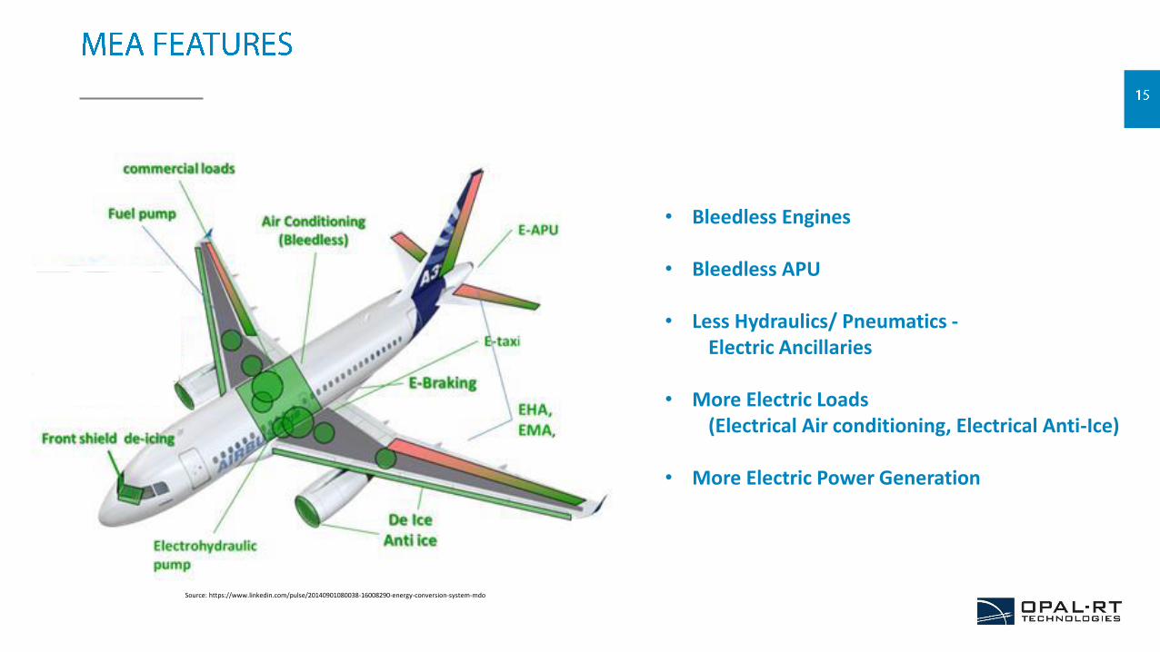
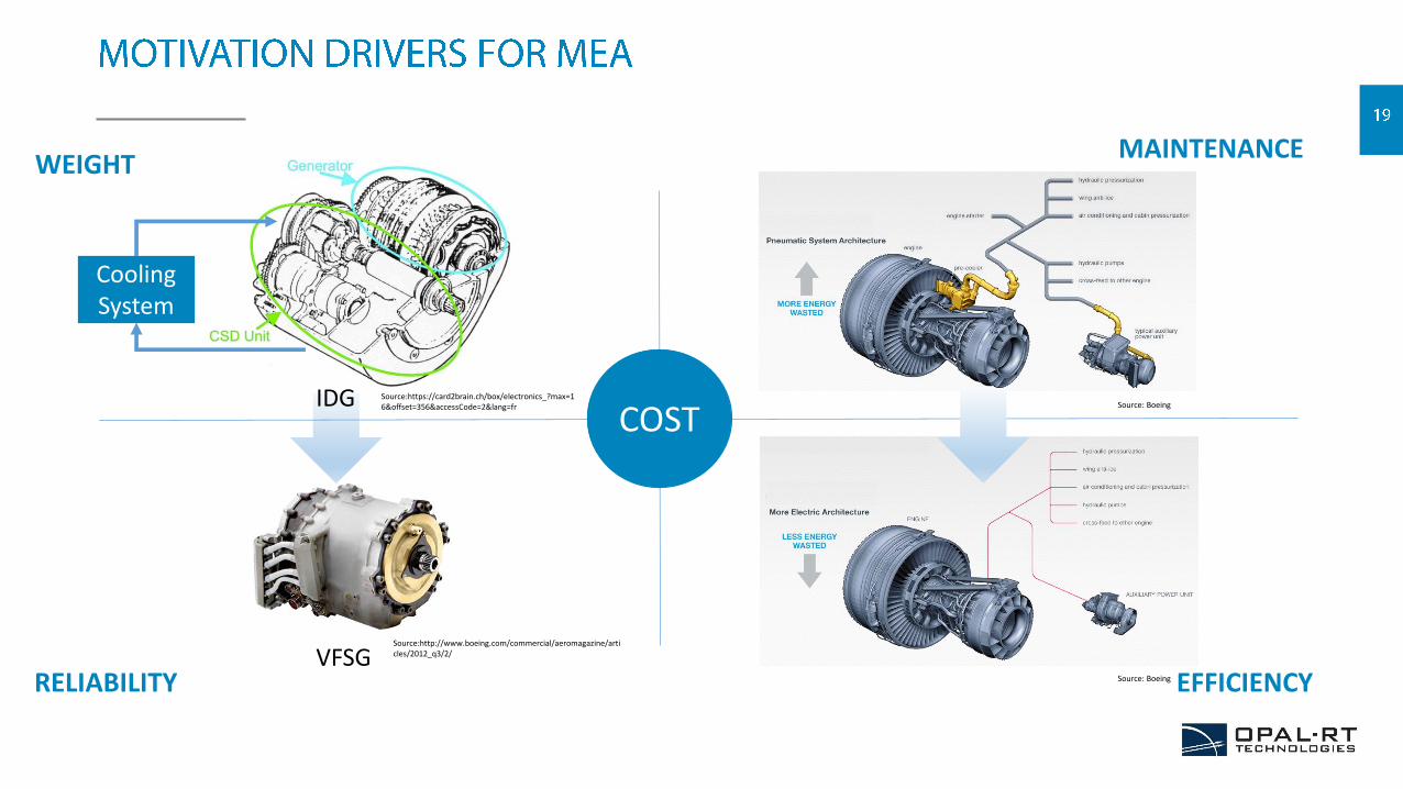
• Bleedless Engines
• Bleedless APU
• Less Hydraulics/ Pneumatics -Electric Ancillaries
• More Electric Loads (Electrical Air conditioning, Electrical Anti-Ice)
• More Electric Power Generation
Source: https://www.linkedin.com/pulse/20140901080038-16008290-energy-conversion-system-mdo
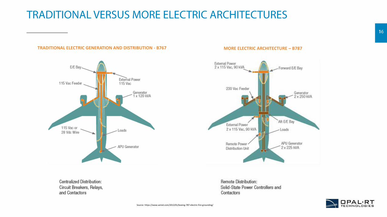
TRADITIONAL ELECTRIC GENERATION AND DISTRIBUTION - B767 MORE ELECTRIC ARCHITECTURE – B787
Source: https://www.wired.com/2013/01/boeing-787-electric-fire-grounding/
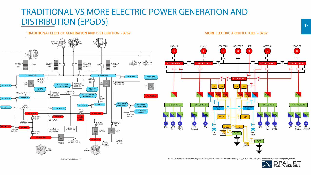
TRADITIONAL ELECTRIC GENERATION AND DISTRIBUTION - B767 MORE ELECTRIC ARCHITECTURE – B787
Source: www.boeing.com Source: http://alverstokeaviation.blogspot.ca/2016/03/the-alverstoke-aviation-society-guide_25.html#!/2016/03/the-alverstoke-aviation-society-guide_25.html
WEIGHT
RELIABILITY
MAINTENANCE
EFFICIENCY
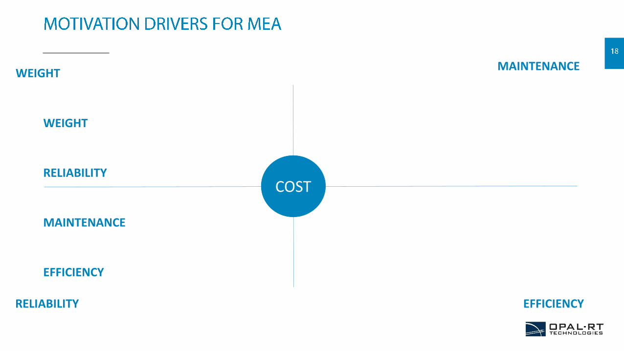
WEIGHTMAINTENANCE
RELIABILITY EFFICIENCY
COST
WEIGHT
RELIABILITY
MAINTENANCE
EFFICIENCY
COST
VFSG
IDG
Cooling System
Source:https://card2brain.ch/box/electronics_?max=16&offset=356&accessCode=2&lang=fr
Source:http://www.boeing.com/commercial/aeromagazine/articles/2012_q3/2/
Source: Boeing
Source: Boeing
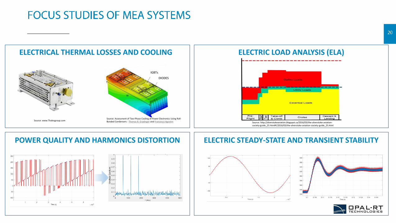
ELECTRICAL THERMAL LOSSES AND COOLING
POWER QUALITY AND HARMONICS DISTORTION
ELECTRIC LOAD ANALYSIS (ELA)
ELECTRIC STEADY-STATE AND TRANSIENT STABILITY
DIODES
IGBTs
Source: http://alverstokeaviation.blogspot.ca/2016/03/the-alverstoke-aviation-society-guide_25.html#!/2016/03/the-alverstoke-aviation-society-guide_25.html
Source: www.Thalesgroup.comSource: Assessment of Two-Phase Cooling of Power Electronics Using Roll-Bonded Condensers - Thomas B. Gradinger and Francesco Agostini
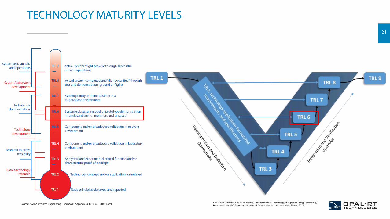
Source: H. Jimenez and D. N. Mavris, “Assessment of Technology Integration using Technology Readiness, Levels”,American Institute of Aeronautics and Astronautics, Texas, 2013.
Source: “NASA Systems Engineering Handbook”, Appendix G, SP-2007-6105, Rev1.
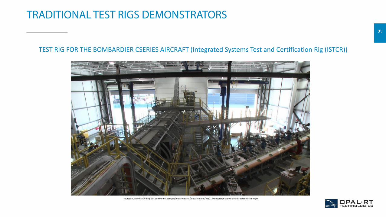
TEST RIG FOR THE BOMBARDIER CSERIES AIRCRAFT (Integrated Systems Test and Certification Rig (ISTCR))
Source: BOMBARDIER- http://ir.bombardier.com/en/press-releases/press-releases/39111-bombardier-cseries-aircraft-takes-virtual-flight
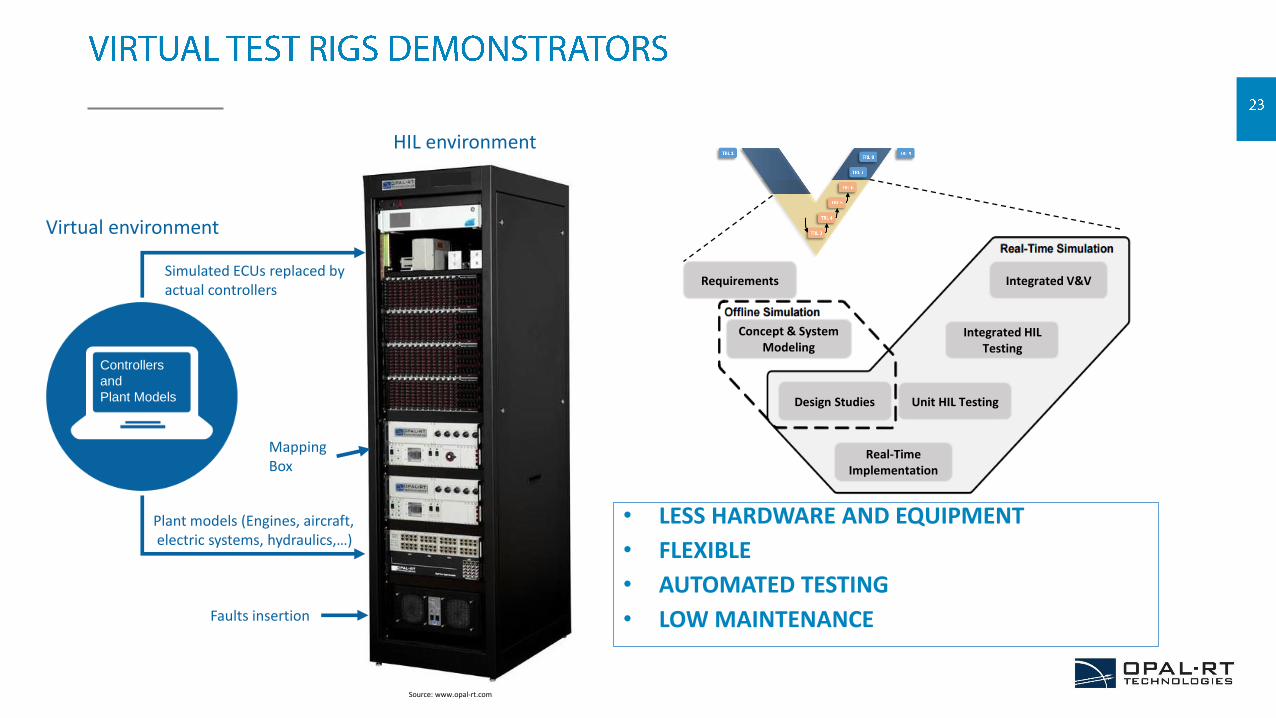
Requirements Integrated V&V
Integrated HIL Testing
Unit HIL Testing
Real-Time Implementation
Design Studies
Concept & System Modeling
Controllers
and
Plant Models
Faults insertion
Plant models (Engines, aircraft,electric systems, hydraulics,…)
Simulated ECUs replaced by actual controllers
Virtual environment
HIL environment
MappingBox
Source: www.opal-rt.com
• LESS HARDWARE AND EQUIPMENT
• FLEXIBLE
• AUTOMATED TESTING
• LOW MAINTENANCE
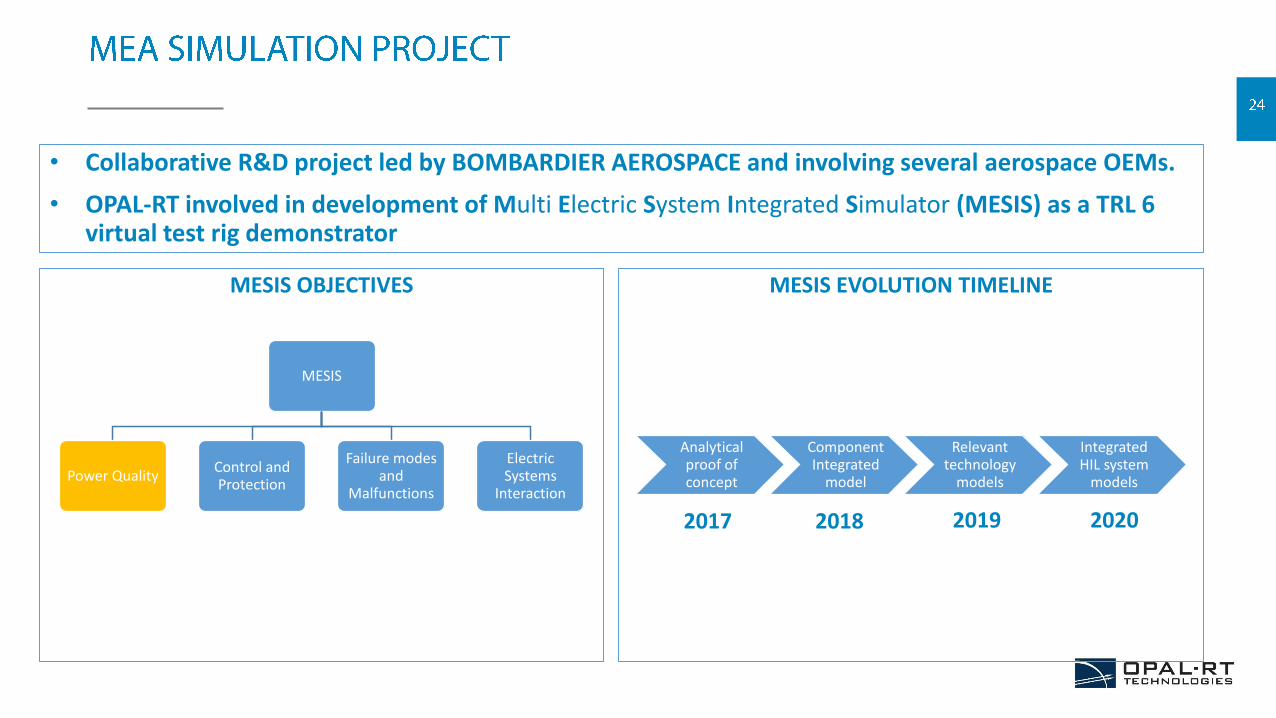
• Collaborative R&D project led by BOMBARDIER AEROSPACE and involving several aerospace OEMs.
• OPAL-RT involved in development of Multi Electric System Integrated Simulator (MESIS) as a TRL 6 virtual test rig demonstrator
MESIS OBJECTIVES MESIS EVOLUTION TIMELINE
Analytical proof of concept
Component Integrated
model
Relevant technology
models
Integrated HIL system
models
MESIS
Power QualityControl and Protection
Failure modes and
Malfunctions
Electric Systems
Interaction
2017 2018 2019 2020
MESIS
Power QualityControl and Protection
Failure modes and
Malfunctions
Electric Systems
Interaction
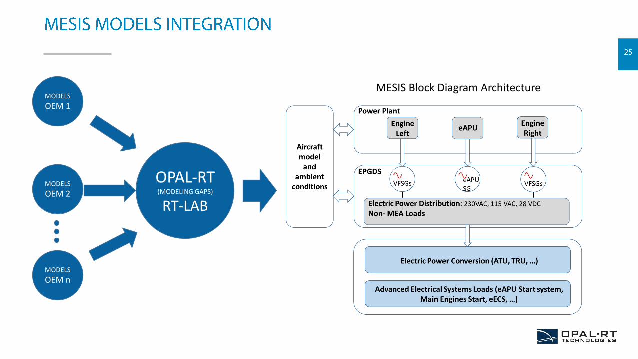
OPAL-RT(MODELING GAPS)
RT-LAB
MODELS
OEM 1
MODELS
OEM 2
MODELS
OEM n
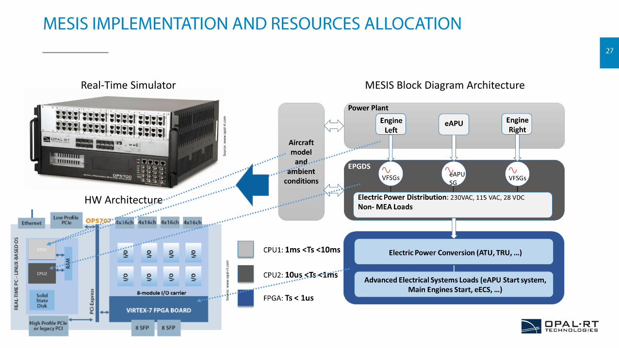
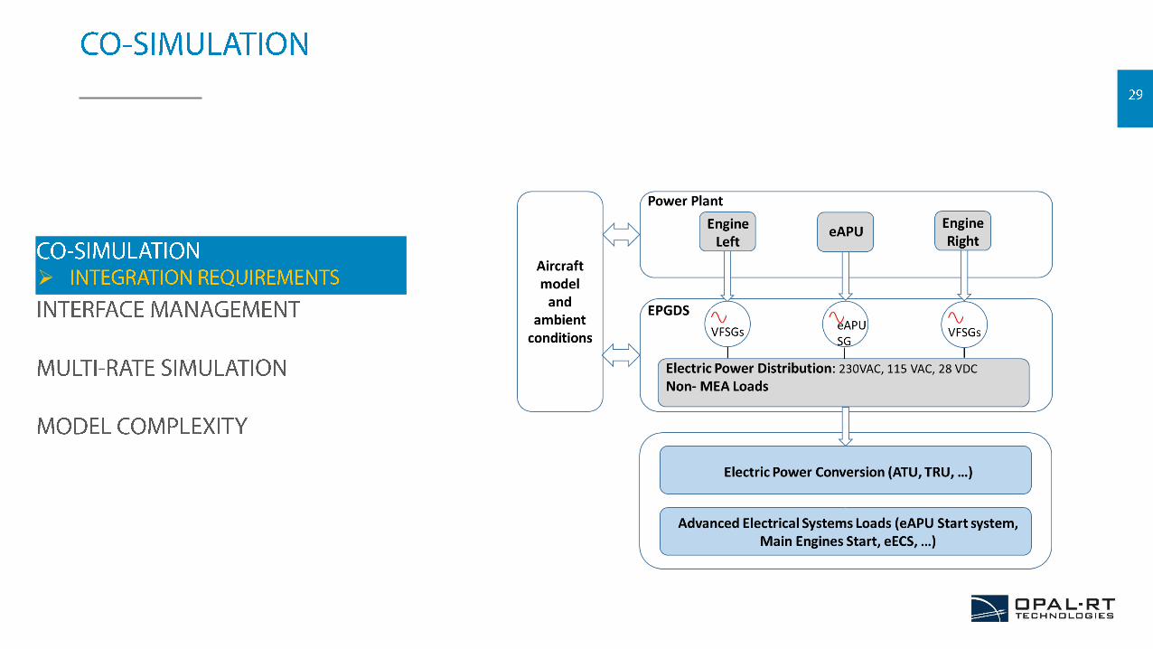
MESIS Block Diagram Architecture
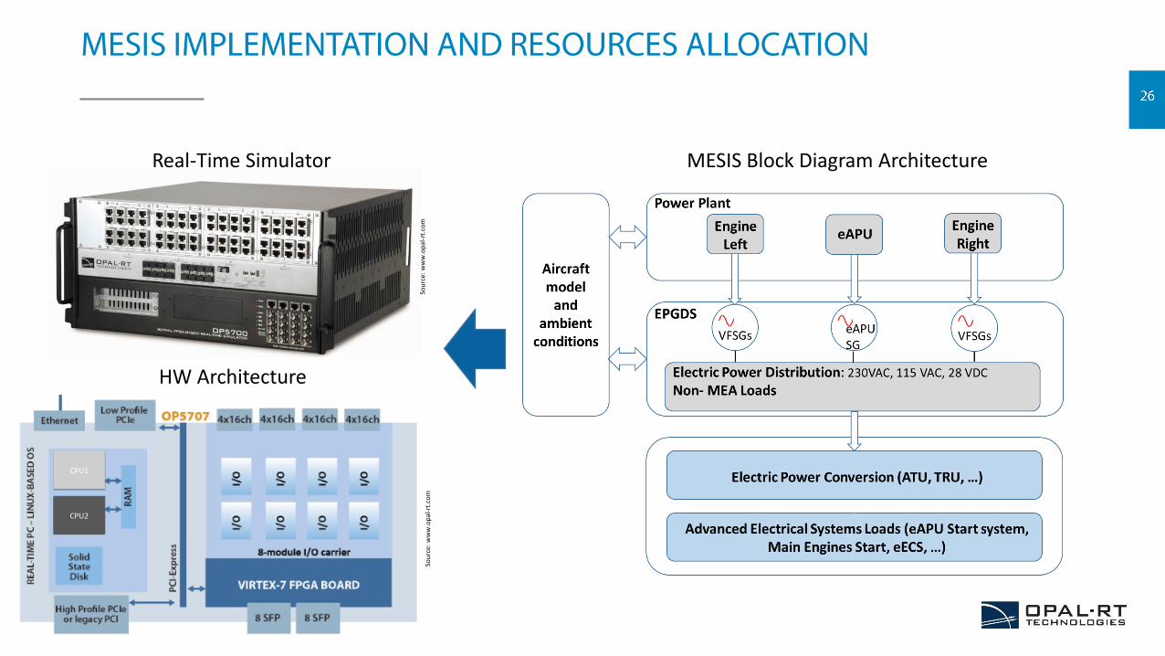
MESIS Block Diagram Architecture Real-Time Simulator
HW Architecture
CPU1
CPU2
Sou
rce:
ww
w.o
pal
-rt.
com
Sou
rce:
ww
w.o
pal
-rt.
com
MESIS Block Diagram Architecture Real-Time Simulator
HW Architecture
CPU1
CPU2
Sou
rce:
ww
w.o
pal
-rt.
com
Sou
rce:
ww
w.o
pal
-rt.
com
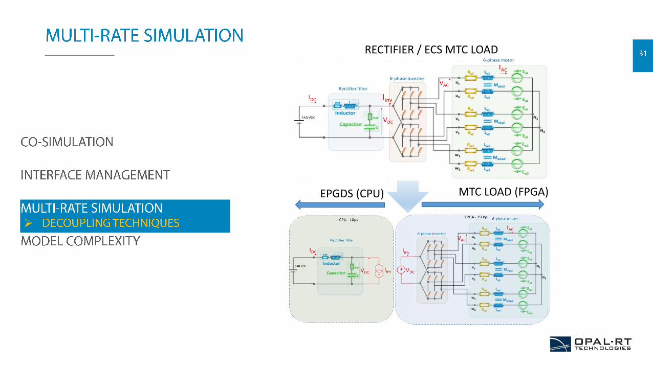
RECTIFIER / ECS MTC LOAD
EPGDS (CPU) MTC LOAD (FPGA)
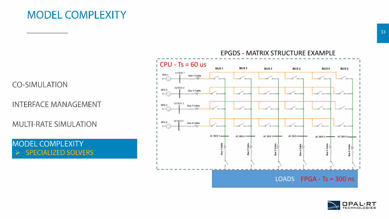
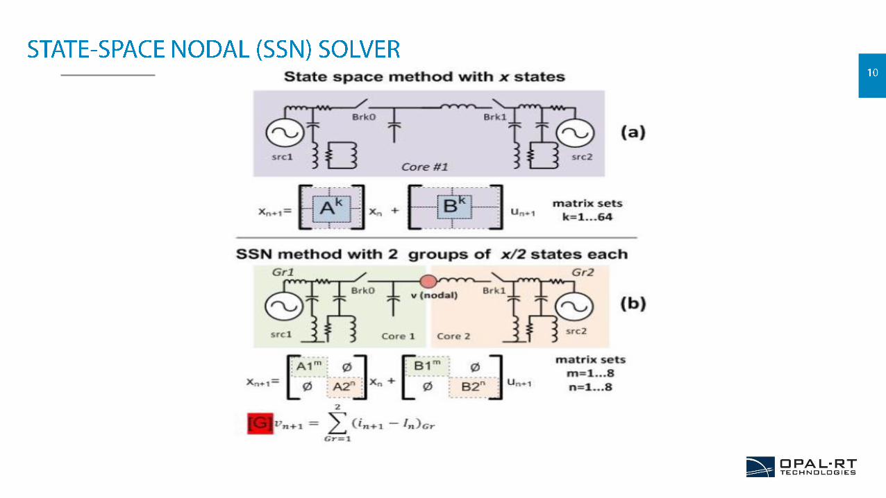
EPGDS - MATRIX STRUCTURE EXAMPLE
CPU - Ts = 60 us
FPGA - Ts = 300 ns
• Competitive reality of MEA Technology
• Real-Time Simulation, a cost effective option for the validation of MEA Technology
• Modeling and Validation of electrical requirements and power quality analysis
• MEA models Co-Simulation is a challenge that isaddressed using specific tools or techniques

Alexandre Leboeuf, B. Eng.
Integration Team Lead
OPAL-RT TECHNOLOGIES
Source: Virginia Polytechnic
• Electronic Systems Integration
• Hardware-in-the-loop
• Case Studies
• Typical Project Time Line
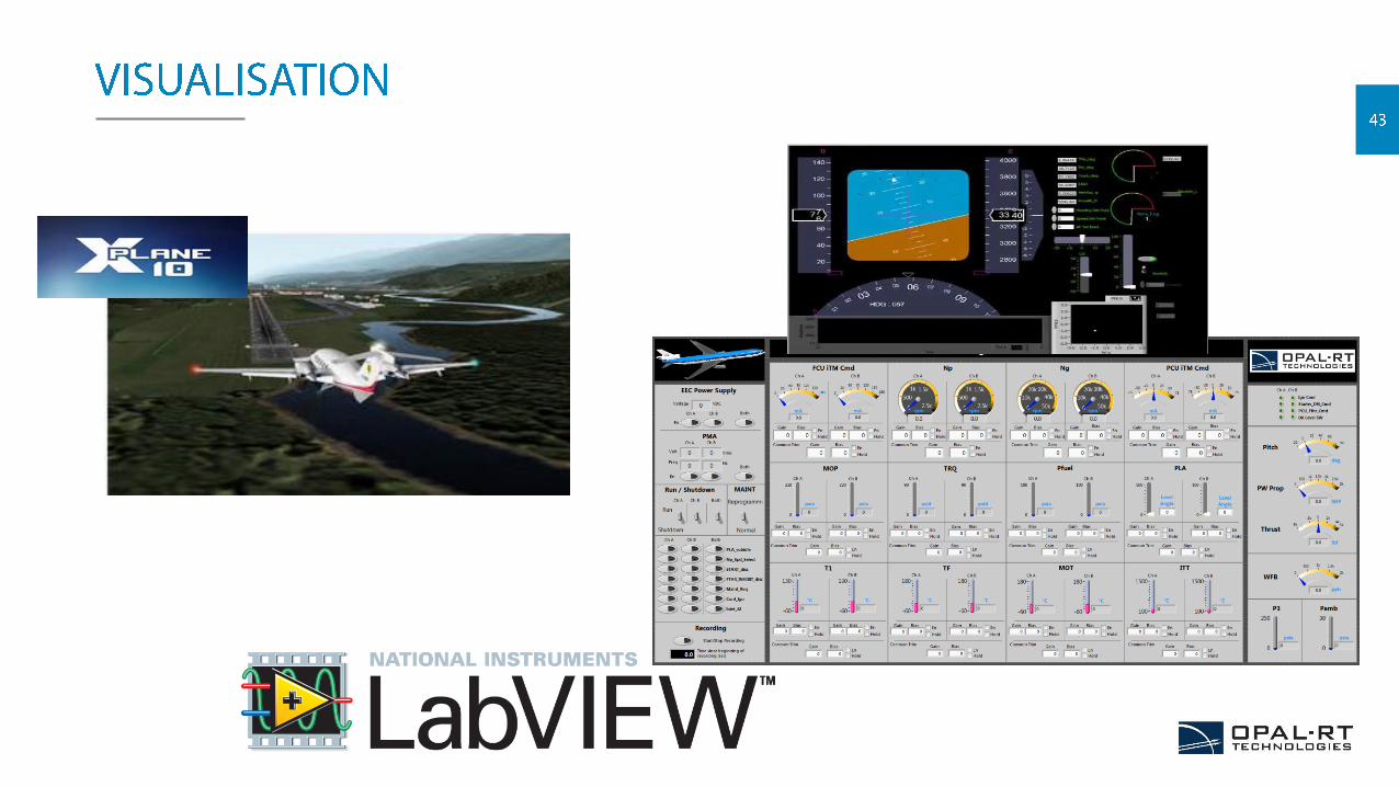
• Automation and Visual Aids
• Benefits and Features
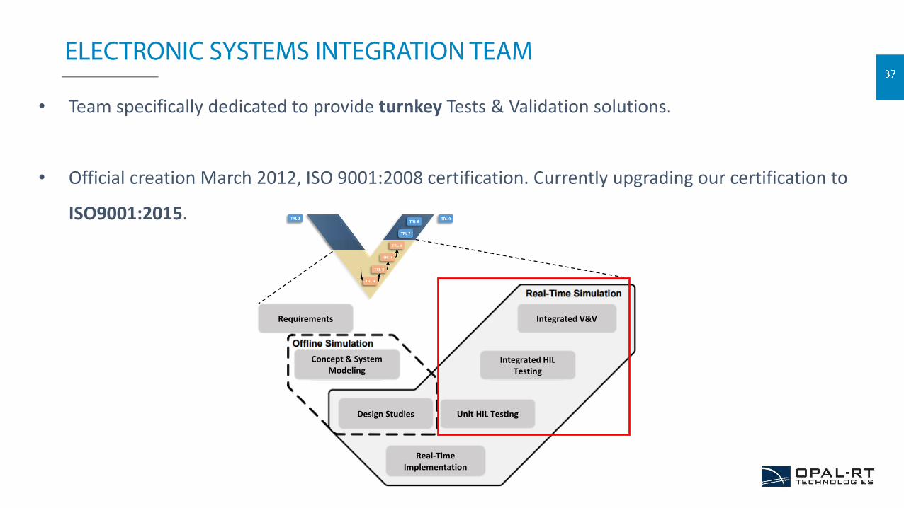
• Team specifically dedicated to provide turnkey Tests & Validation solutions.
• Official creation March 2012, ISO 9001:2008 certification. Currently upgrading our certification to
ISO9001:2015.
Requirements Integrated V&V
Integrated HIL Testing
Unit HIL Testing
Real-Time Implementation
Design Studies
Concept & System Modeling
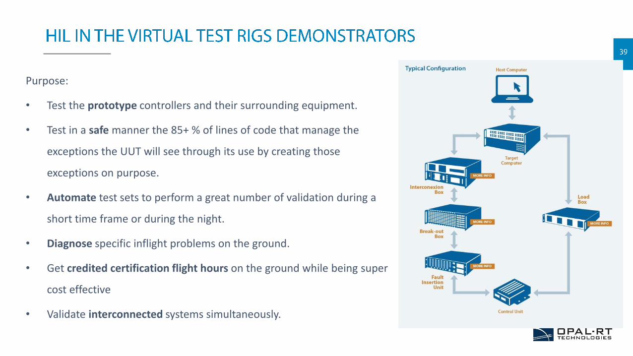
Purpose:
• Test the prototype controllers and their surrounding equipment.
• Test in a safe manner the 85+ % of lines of code that manage the
exceptions the UUT will see through its use by creating those
exceptions on purpose.
• Automate test sets to perform a great number of validation during a
short time frame or during the night.
• Diagnose specific inflight problems on the ground.
• Get credited certification flight hours on the ground while being super
cost effective
• Validate interconnected systems simultaneously.
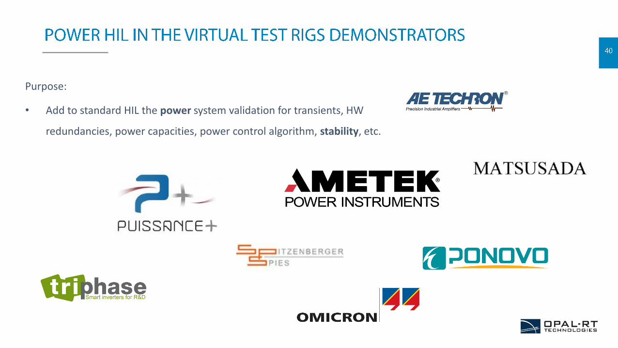
Purpose:
• Add to standard HIL the power system validation for transients, HW
redundancies, power capacities, power control algorithm, stability, etc.
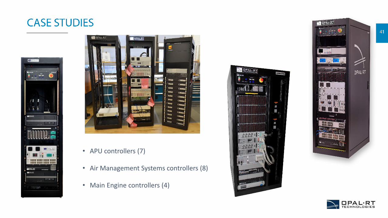
• APU controllers (7)
• Air Management Systems controllers (8)
• Main Engine controllers (4)
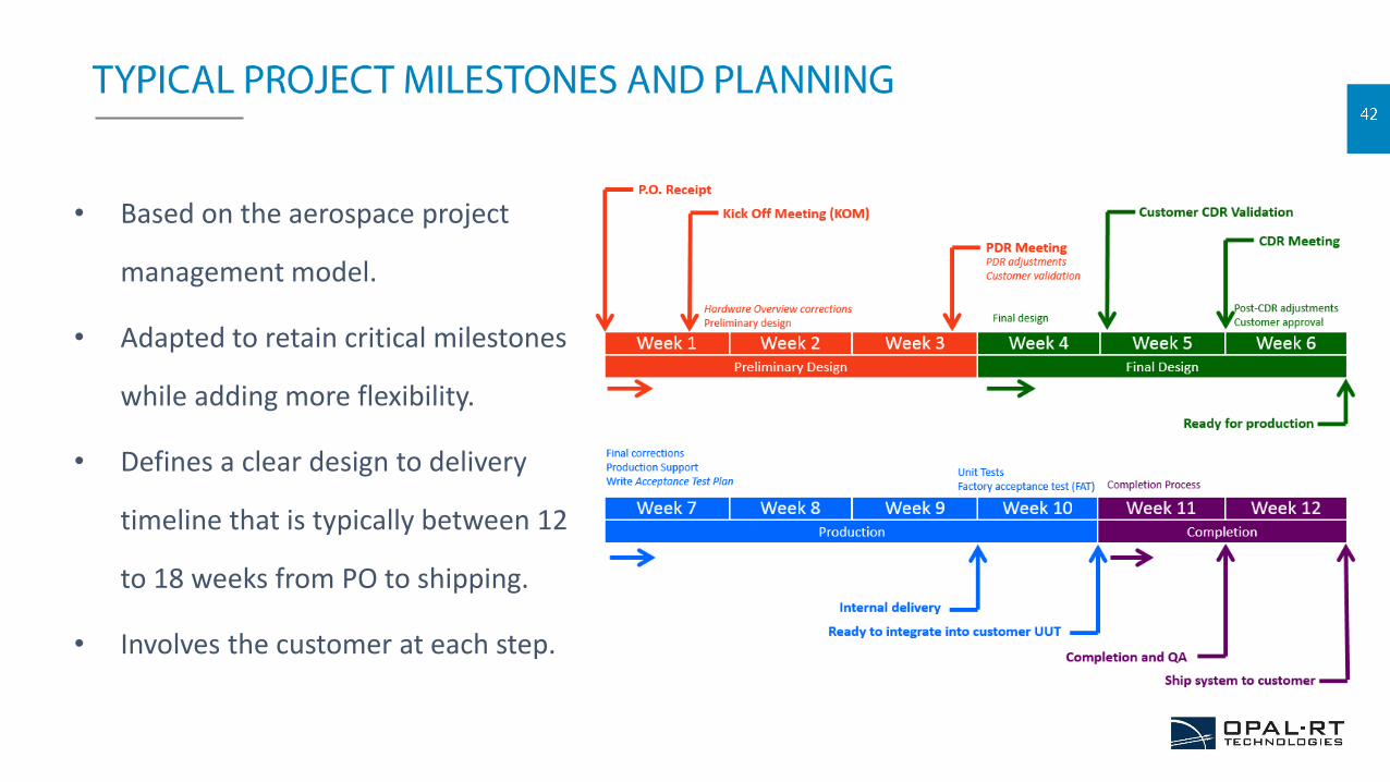
• Based on the aerospace project
management model.
• Adapted to retain critical milestones
while adding more flexibility.
• Defines a clear design to delivery
timeline that is typically between 12
to 18 weeks from PO to shipping.
• Involves the customer at each step.
Throttle_R
20
Hagl_m
19
Mext
18
Zext
17
Rudder
16
Aileron
15
Elevator
14
Psi
13
Theta
12
Phi
11
Altitude_ft
10
Mach
9
Climb
8
Thrust
7
DeltaThrottle
6
Nz
5
Ny
4
Track
3
Beta
2
Gamma
1
KIAS
TP
Target_Points
Pioneer_Aircraft
FromNavlRU
FromNavADC
FromNavFSC
FromAutoPilot
FromControls
FromEqm
FromAtm
FromEngine
EQM_Out
TJetEng_Out
Atm_Out
Ctrl_Out
OpXPlane_out
Outputs
OpComm
Ts = 0.01
OpComm1
17
AutoPilotON
16
NoseWheel
15
Brake
14
Booster_ON
13
FuelCut_RH
12
FuelCut_LH
11
GearDown
10
VertWind
9
WindDir_Deg
8
WindSpeed_kt
7
Throttle_RH
6
Throttle_LH
5
TrimCmd
4
FlapSlatLever
3
Pedal
2
Wheel
1
Column
<VD_mps>
<Phi_deg>
<The_deg>
<Psi_deg>
<Gamma_deg>
<Track_deg>
<Ny>
<Nz>
<DeltaThr>
<KIAS>
<Beta>
<PresAlt_ft>
<Mach>
<Thrust_Kgf>
<Elev_deg>
<Ail_deg>
<Rud_deg>
<Zext>
<Mext>
<Hagl_m>
Col
Wheel
Pedal
FlapLev
Throttle_L
TargetPoints
Column
Wheel
Pedal
FlapSlatLev er
TrimCmd
Throttle_LH
Throttle_RH
GearDown
GearDown
Horiz_Wind_Speed
Horiz_Wind_Dir
Vert_Wind_Speed
FuelCut_LH
FuelCut_RH
BoosterON
Brake
NoseWheel
AutoPilotON
AutoPilot
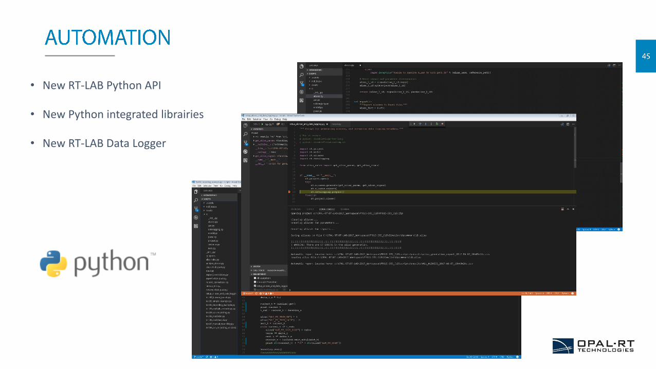
• New RT-LAB Python API
• New Python integrated librairies
• New RT-LAB Data Logger
• We control the full business chain: Systems Integration team has a direct influence on HW/SW designs in accordance with real customer
requirements.
Overheads are limited with in-house products and procurement.
Support is handled directly by OPAL-RT.
• Open architecture permitting easy interface with existing simulation solutions.
• Modular design provides the means to expand the system with controlled cost.
• HW/SW for power electronics simulation as a backbone to propel MEA test bench designs.
• Simplified project management provides complex system delivery in short time frames. (Typically 12 to 18 weeks)
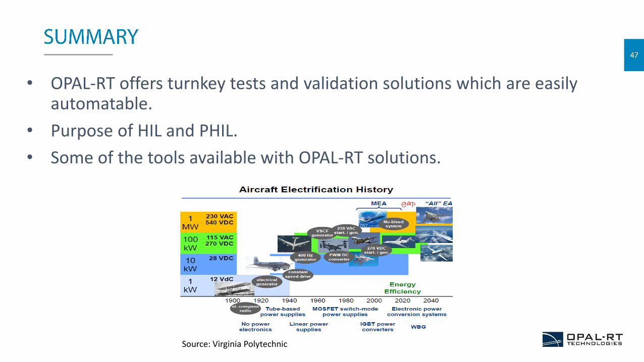
• OPAL-RT offers turnkey tests and validation solutions which are easily automatable.
• Purpose of HIL and PHIL.
• Some of the tools available with OPAL-RT solutions.
Source: Virginia Polytechnic
RT17 - OPAL-RT’s 9th User Group Conference
• September 5th to 8th, 2017 // Montreal, QC, Canada
• Register now to benefit from the early bird deadline -www.opal-rt.com/rt17
• Celebrating OPAL-RT’s 20th anniversary!
SAE 2017 AeroTech Congress & Exhibition
• 26 Sep to 28 Sep 2017 // Forth Worth, United States
• Visit us at booth # 914
• Learn more at www.opal-rt.com/event/sae-2017-aerotech-congress-exhibition/
The slides and recording of this presentation will beshare with you by email shortly.