Embed Size (px)
Citation preview

Report on Preliminary Geotechnical Investigation
Proposed Correctional Centre Upgrade 55 The Links Road, South Nowra
Prepared for Guymer Bailey Architects
Project 48600.06 June 2016


Report on Preliminary Geotechnical Investigation 48600.06.R.001.docx Proposed Correctional Centre Upgrade June 2016 55 The Links Road, South Nowra
Table of Contents
Page
1. Introduction..................................................................................................................................... 1
2. Background .................................................................................................................................... 1
3. Site Description and Regional Geology ......................................................................................... 2
4. Field Work ...................................................................................................................................... 2
4.1 Methods ............................................................................................................................... 2
4.2 Results ................................................................................................................................. 3
5. Laboratory Testing ......................................................................................................................... 3
5.1 Geotechnical ........................................................................................................................ 3
5.2 Contamination ...................................................................................................................... 4
6. Proposed Development .................................................................................................................. 5
7. Comments ...................................................................................................................................... 5
7.1 General ................................................................................................................................ 5
7.2 Site Classification ................................................................................................................. 5
7.3 Salinity Considerations ........................................................................................................ 6 7.4 Contamination ...................................................................................................................... 6
7.5 Footings ............................................................................................................................... 7
7.6 Site Maintenance and Drainage .......................................................................................... 8
8. References ..................................................................................................................................... 8
9. Limitations ...................................................................................................................................... 8
Appendix A: About This Report
Appendix B: Previous Cottier Borehole Logs (Bores BH05 – BH20) Previous DP Test Pit Logs (Pits 1 – 4) Current Borehole Logs (Bores 101 – 112) Site photographs Drawing 1
Appendix C: Results of Laboratory Tests
Appendix D: Table D1: Contamination Laboratory Summary Table Laboratory Certificate of Analysis Sample Receipt Advice Chain-of-Custody Documentation
Appendix E: Building in a Saline Environment CSIRO Foundation Publication
Page 1 of 9
Report on Preliminary Geotechnical Investigation 48600.06.R.001.docx Proposed Correctional Centre Upgrade June 2016 55 The Links Road, South Nowra
Report on Preliminary Geotechnical Investigation Proposed Correctional Centre Upgrade 55 The Links Road, South Nowra 1. Introduction
This report presents the results of a preliminary geotechnical investigation undertaken for the proposed upgrade to the South Coast Correctional Centre at 55 The Links Road, South Nowra. The investigation was commissioned by Guymer Bailey Architects and undertaken in accordance with Douglas Partners proposal WOL160077.P.003 dated 17 February 2016. It is understood that the proposed Stage 2 development comprises the installation of modular accommodation within the existing correctional centre footprint or the construction of additions to the south of the correctional centre. It is further understood that consideration is also being given to an expansion to the north of the existing development (exact location yet to be determined). The investigation comprised a review of existing geotechnical information and the drilling of twelve boreholes with in-situ testing and sampling followed by laboratory testing of selected samples, engineering analysis, liaison and reporting. Details of the field work undertaken and the results obtained are given in the report, together with comments relating to design and construction practice. The results of preliminary contamination and salinity testing of the site soils are also discussed within the report. A site layout was provided by the client who also nominated the test locations for the investigation. 2. Background
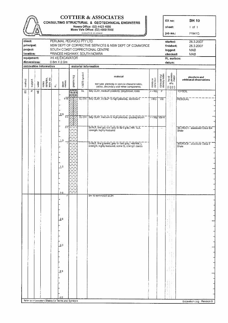
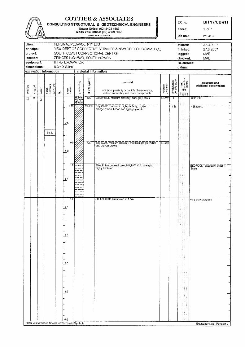
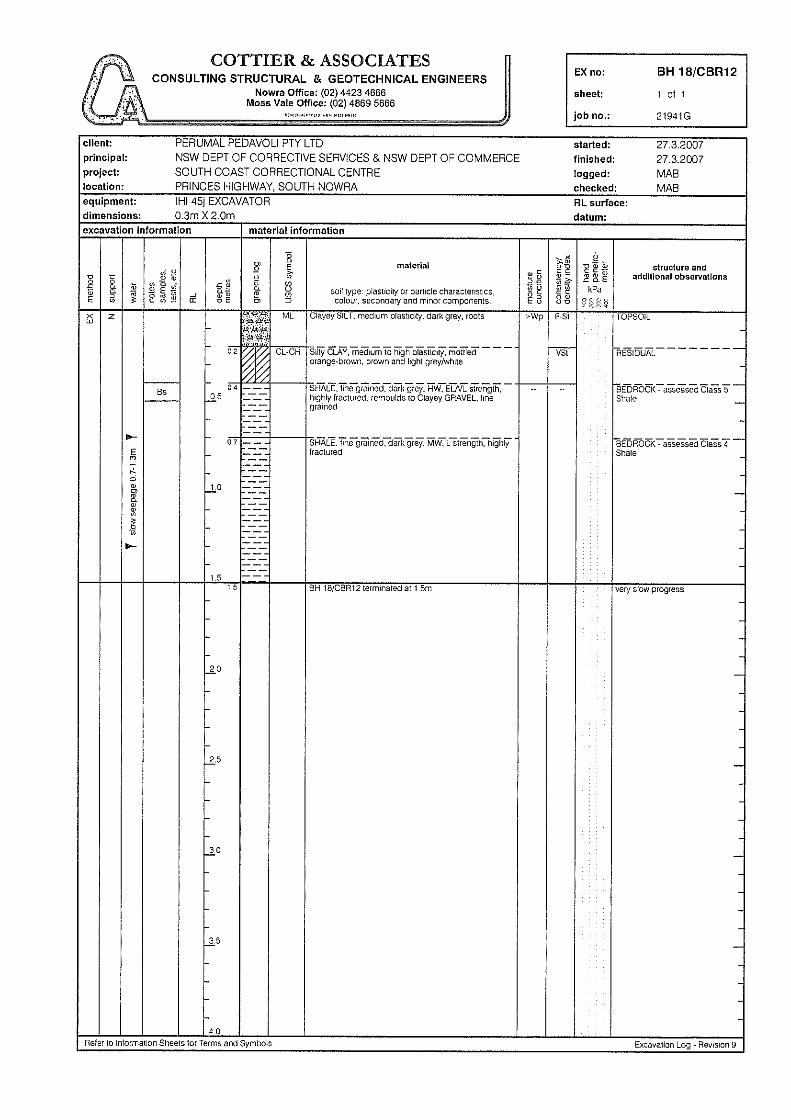
Previous geotechnical investigations have previously been undertaken by Douglas Partners (DP) and Cottier and Associates (CA) on the site. The relevant reports are:
• CA Project 21941G(4): mab "South Coast Correctional Centre, Princes Highway, South Nowra" dated 7 May 2007;
• DP Project 48600.06 "Damaged Pavements" (memo) dated 14 December 2010.
The relevant test pit and borehole logs from the previous investigations are included in Appendix B with the approximate locations of the previous field tests shown on Drawing 1.

Page 2 of 9
Report on Preliminary Geotechnical Investigation 48600.06.R.001.docx Proposed Correctional Centre Upgrade June 2016 55 The Links Road, South Nowra
3. Site Description and Regional Geology
The South Coast Correctional Centre, which includes Lots 102 & 103 in DP 755952, Lot 30 in 1169494, Lot 2 in DP 1112040 and Lot 7041 in DP 1121435, is an irregular-shaped area of approximately 145 ha with maximum north-south and east-west dimensions of 1,250 m and 1,190 m respectively. It is bounded to the north by The Links Road and existing commercial development, to the east by the Princes Highway and existing commercial development and to the south end east by undeveloped Crown reserve and rural land. Surface levels fall generally in the north-easterly direction at grades of 1 in 30 to 1 in 40, with an overall difference in levels estimated to be about 15 m from the highest part of the site to the lowest. The estimated difference in level across the developed area is about 8 m. At the time of the investigation, the site was an active correctional centre comprising a series of detention blocks, administration buildings, internal lightly grassed areas and car park areas. The remainder of the site (i.e. outside the fenced area) was mainly undeveloped and moderately timbered. A previous quarry is located in the eastern section of the overall site. Various features observed during the investigation are shown on the colour photoplates in Appendix B. Reference to the 1:250 000 New South Wales Statewide geodatabase indicates that the site is underlain by sandstone, siltstone, shale, claystone and conglomerate belonging to the Shoalhaven Group of Permian age. The results of the investigation were consistent with the geological mapping with shale encountered in ten of the twelve boreholes drilled for the current investigation. 4. Field Work
4.1 Methods
The current field work comprised the drilling of twelve boreholes (Bores 101 – 112) to depths in the range 0.5 m to 3.0 m with a Kubota KX018-4 mini-excavator fitted with a 150 mm diameter power auger. The boreholes were logged on site by a geotechnical engineer who collected disturbed and "undisturbed" samples (in 50 mm diameter thin-walled tubes) at regular depth intervals to assist in strata identification and for laboratory testing. Dynamic cone penetrometer tests (DCP, AS1289 6.3.2) were undertaken adjacent to eight of the twelve boreholes to assess the penetration resistance of the upper 0.3 – 1.2 m of the subsurface profile. The locations of the boreholes are shown on Drawing 1 (Appendix B). The surface levels (to Australian Height Datum, AHD) were determined by contour interpolation from web-based mapping. The coordinates to (Map Grid Australia, MGA) were determined using a hand-held GPS receiver. As such, the levels and coordinates are approximate only. During borehole drilling, environmental samples were collected from near the surface (ie topsoil) and successive at 0.5 m intervals into natural clay at six of the twelve geotechnical borehole locations for possible laboratory testing.

Page 3 of 9
Report on Preliminary Geotechnical Investigation 48600.06.R.001.docx Proposed Correctional Centre Upgrade June 2016 55 The Links Road, South Nowra
4.2 Results
Details of the conditions encountered in the boreholes are given on the borehole logs in Appendix B. These should be read in conjunction with the accompanying notes defining classification methods and descriptive terms. Relatively uniform conditions were encountered underlying the site, with the succession of strata broadly summarised as follows: TOPSOIL: to 0.1 m depth in Bore 106 only;
FILLING: apparently well compacted, gravelly clay to depths of 0.1 – 1.0 m in Bores 101, 102, 105, 107, 109 – 112, and to the termination depths of 1.0 m in Bore 103 and 3.0 m in Bore 108;
CLAY: stiff to very stiff clay and gravelly clay to depths of 0.5 – 3.0 m in Bores 101,
102, 104 – 107 and 109 – 112;
SHALE: initially variably extremely low to low strength becoming low to medium strength at refusal of the auger at depths of 0.5 – 3.0 m in Bores 101, 102, 104 – 107 and Bores 109 – 112.
No free groundwater was observed in the boreholes during auguring for the short time that they were left open. It is noted that the boreholes were immediately backfilled following drilling, sampling and logging which precluded long term monitoring of groundwater levels. 5. Laboratory Testing
5.1 Geotechnical
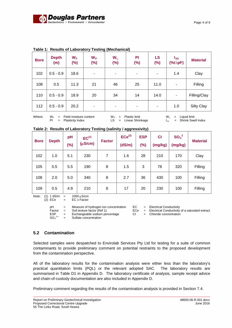
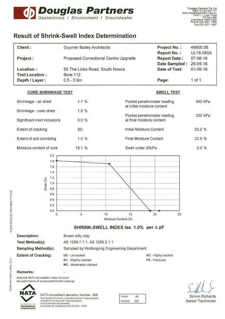
Selected samples from the boreholes were tested in the laboratory for measurement of field moisture content, Atterberg limits, linear shrinkage, pH, electrical conductivity, salinity and chloride/sulphate concentrations. The detailed laboratory test report sheets are given in Appendix C and the results summarised in Tables 1 & 2 (following page). The results indicate that the clays tested are of low to intermediate plasticity and would be expected to be susceptible to shrinkage and swelling movements with changes in soil moisture content. The results also indicate that the site soils are typically "highly sodic" (ie ESP greater than 15%). The sample from Bore 105 / 0.5 m is "non-sodic". Furthermore, the soils are generally classified as "non-saline" (i.e. ECe < 2 dS/m). The sample from Bore 108/2.0 m is "slightly saline" (i.e. ECe between 2 dS/m and 4 dS/m). The results also indicate that the soils tested can be classified as "mildly aggressive" to concrete and "non-aggressive" to steel with reference to AS 2159 – 2009 (Ref 2). Further discussion on the implications of the salinity and sodicity testing is given in Section 7.3.
Page 4 of 9
Report on Preliminary Geotechnical Investigation 48600.06.R.001.docx Proposed Correctional Centre Upgrade June 2016 55 The Links Road, South Nowra
Table 1: Results of Laboratory Testing (Mechanical)
Bore Depth (m)
WF
(%) WP (%)
WL (%)
PI (%)
LS (%)
ISS
(%/∆pF) Material
102 0.5 - 0.9 18.6 - - - - 1.4 Clay
108 0.5 11.3 21 46 25 11.0 - Filling
110 0.5 - 0.9 18.9 20 34 14 14.0 - Filling/Clay
112 0.5 - 0.9 20.2 - - - - 1.0 Silty Clay
Where: WF = Field moisture content WP = Plastic limit WL = Liquid limit PI = Plasticity Index LS = Linear Shrinkage Iss = Shrink Swell Index Table 2: Results of Laboratory Testing (salinity / aggressivity)
Bore Depth pH
(%) EC(1)
(µS/cm) Factor ECe(2)
(dS/m)
ESP
(%)
CI
(mg/kg)
SO42
(mg/kg) Material
102 1.0 5.1 230 7 1.6 28 210 170 Clay
105 0.5 5.5 190 8 1.5 3 78 320 Filling
108 2.0 5.0 340 8 2.7 36 430 100 Filling
109 0.5 4.9 210 8 17 20 230 100 Filling
Note: (1) 1 dS/m = 1000 µS/cm (2) ECe = EC x Factor pH = Measure of hydrogen ion concentration EC = Electrical Conductivity Factor = Soil texture factor (Ref 1) ECe = Electrical Conductivity of a saturated extract ESP = Exchangeable sodium percentage CI- = Chloride concentration SO4
2-= = Sulfate concentration 5.2 Contamination
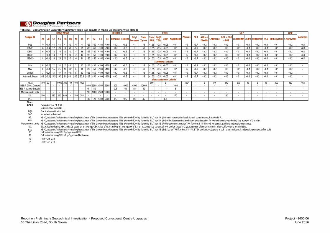
Selected samples were despatched to Envirolab Services Pty Ltd for testing for a suite of common contaminants to provide preliminary comment on potential restraints to the proposed development from the contamination perspective. All of the laboratory results for the contamination analysis were either less than the laboratory’s practical quantitation limits (PQL) or the relevant adopted SAC. The laboratory results are summarised in Table D1 in Appendix D. The laboratory certificate of analysis, sample receipt advice and chain-of-custody documentation are also included in Appendix D. Preliminary comment regarding the results of the contamination analysis is provided in Section 7.4.

Page 5 of 9
Report on Preliminary Geotechnical Investigation 48600.06.R.001.docx Proposed Correctional Centre Upgrade June 2016 55 The Links Road, South Nowra
6. Proposed Development
It is understood that the proposed Stage 2 development comprises the installation of accommodation modules within the existing correctional centre footprint and/or the construction of additions to the south of the correctional centre. Upgrade works are also being considered to the north of the centre (ie in the vicinity of the existing car parks). Whilst the exact location and nature of the proposed structures was not determined at the time of this report, it is anticipated that minimal earthworks will be required to achieve design levels and structural loads will be commensurate with conventional residential construction. 7. Comments
7.1 General
The following comments are based on a review of available information, the results of the subsurface investigation and laboratory testing and preliminary information provided by the client. Given the preliminary nature of the overall planning and design of the proposed works, further investigations may need to be undertaken at the appropriate time as the planning and design of the individual buildings proceeds. Accordingly, this report and the comments given within must be considered as being preliminary only. 7.2 Site Classification
The presence of filling to depths in excess of 0.4 m (in part) necessitates a P classification in accordance with AS 2870 – 2011 Residential Slabs and Footings (Ref 3). The main requirement for a Class P site is for design to be undertaken by a suitably qualified engineer using engineering principles that take into account the subsurface conditions and the recommendations of this report. Notwithstanding the P classification, given the apparent well compacted nature of the filling observed at the borehole locations, it is considered that provided additional DCP testing is undertaken at the proposed structure locations following footing excavation, the profiles are considered commensurate with Class M (moderately reactive) conditions. It is noted however, that site classification is independent of proposed construction and serves only to classify the site in terms of soil reactivity. Furthermore, the foundation details given in AS 2870 – 2011 Residential Slabs and Footings (Ref 3) are appropriate for residential buildings and its applicability to this site will need to be determined by the design engineer undertaken by suitably qualified engineers using engineering principles which take into account subsurface conditions determined by geotechnical investigation.
Page 6 of 9
Report on Preliminary Geotechnical Investigation 48600.06.R.001.docx Proposed Correctional Centre Upgrade June 2016 55 The Links Road, South Nowra
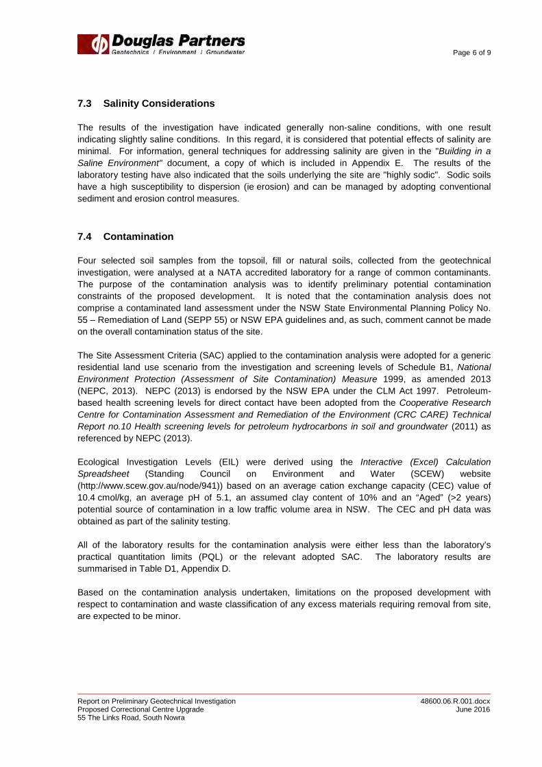
7.3 Salinity Considerations
The results of the investigation have indicated generally non-saline conditions, with one result indicating slightly saline conditions. In this regard, it is considered that potential effects of salinity are minimal. For information, general techniques for addressing salinity are given in the "Building in a Saline Environment" document, a copy of which is included in Appendix E. The results of the laboratory testing have also indicated that the soils underlying the site are "highly sodic". Sodic soils have a high susceptibility to dispersion (ie erosion) and can be managed by adopting conventional sediment and erosion control measures. 7.4 Contamination
Four selected soil samples from the topsoil, fill or natural soils, collected from the geotechnical investigation, were analysed at a NATA accredited laboratory for a range of common contaminants. The purpose of the contamination analysis was to identify preliminary potential contamination constraints of the proposed development. It is noted that the contamination analysis does not comprise a contaminated land assessment under the NSW State Environmental Planning Policy No. 55 – Remediation of Land (SEPP 55) or NSW EPA guidelines and, as such, comment cannot be made on the overall contamination status of the site. The Site Assessment Criteria (SAC) applied to the contamination analysis were adopted for a generic residential land use scenario from the investigation and screening levels of Schedule B1, National Environment Protection (Assessment of Site Contamination) Measure 1999, as amended 2013 (NEPC, 2013). NEPC (2013) is endorsed by the NSW EPA under the CLM Act 1997. Petroleum-based health screening levels for direct contact have been adopted from the Cooperative Research Centre for Contamination Assessment and Remediation of the Environment (CRC CARE) Technical Report no.10 Health screening levels for petroleum hydrocarbons in soil and groundwater (2011) as referenced by NEPC (2013). Ecological Investigation Levels (EIL) were derived using the Interactive (Excel) Calculation Spreadsheet (Standing Council on Environment and Water (SCEW) website (http://www.scew.gov.au/node/941)) based on an average cation exchange capacity (CEC) value of 10.4 cmol/kg, an average pH of 5.1, an assumed clay content of 10% and an “Aged” (>2 years) potential source of contamination in a low traffic volume area in NSW. The CEC and pH data was obtained as part of the salinity testing. All of the laboratory results for the contamination analysis were either less than the laboratory’s practical quantitation limits (PQL) or the relevant adopted SAC. The laboratory results are summarised in Table D1, Appendix D. Based on the contamination analysis undertaken, limitations on the proposed development with respect to contamination and waste classification of any excess materials requiring removal from site, are expected to be minor.

Page 7 of 9
Report on Preliminary Geotechnical Investigation 48600.06.R.001.docx Proposed Correctional Centre Upgrade June 2016 55 The Links Road, South Nowra
7.5 Footings
All footing systems should be designed and constructed in accordance with engineering principles which take into account subsurface profiles and proposed loads. The selection of bearing stratum will be dependent on the type of structures, the proposed loads and the resultant settlements. Project-specific geotechnical investigation with subsurface profiling should be undertaken at the appropriate time as planning proceeds in order to determine appropriate foundation systems for the various structures. As a guide, typical bearing pressures on various strata are as follows:
• Allowable base bearing on stiff clay or compacted filling 150 kPa (for column loads up to 300 kN and live loads of 100 kN/m)
• Allowable base bearing on very low to low strength rock 700 kPa
• Allowable base bearing on low to medium strength rock 1,500 kPa The feasibility of using a high level footing system will depend on structural loads and resultant settlements. As a guide, working loads on high level footings should be limited to 300 kN and 100 kN/m, which would result in settlements of up to 10 – 15 mm for 1.4 m wide square footings. Differential settlements could approach 5 – 10 mm as a result of variable depth of soil (filling and natural clay) overlying rock. In the event that high level footings are considered to be appropriate, consideration will need to be given to in structural detailing to accommodate the presence of reactive clays. The provisions of AS 2870 (Ref 3) for Class M sites should form a basis of protecting the foundation system from shrink-swell movement of the soil profile. Furthermore, detailed inspections and dynamic cone penetrometer testing must be undertaken to confirm the appropriateness of the founding stratum for the adopted design pressure. Where footing systems are proposed adjacent to services or located near retaining walls, local deepening of the footings or alternatively, the inclusion of piers will most likely be required. Founding levels are to be within the underlying very stiff clays/weathered rock below the zone of influence of the service trench and any retaining walls, with the zone of influence defined as an imaginary line extending from the base of the trench to the ground surface inclined at 45° (i.e. 1 horizontal:1 vertical). If the estimated settlements are beyond tolerable limits or if higher loads are proposed, footings founded on rock would be required. Rock was encountered within Bores 101, 102, 104 – 107 and Bores 109 – 112 at depths of 0.5 – 3.0 m. Pad and strip footings could be utilised where rock is within, say, 1.2 of the prepared surface and bored piers elsewhere. The main advantage of a footings-to-rock system would be that settlements (both total and differential) would be negligible. As a guide, a 500 mm diameter pier founded on medium strength rock could support a working load of 290 kN. All footing systems should be designed and constructed in accordance with sound engineering principles, with care exercised to ensure that footing trenches/piers are inspected for design compliance prior to the placement of steel and the pouring of concrete. Footings should also be inspected by a suitably qualified geotechnical engineer together with additional dynamic cone penetrometer testing prior to the placement of steel and of concrete to confirm the appropriateness of the bearing stratum for the adopted design pressures.

Page 8 of 9
Report on Preliminary Geotechnical Investigation 48600.06.R.001.docx Proposed Correctional Centre Upgrade June 2016 55 The Links Road, South Nowra
7.6 Site Maintenance and Drainage
The developed site should be maintained in accordance with the CSIRO publication “Guide to Home Owners on Foundation Maintenance and Footing Performance”, a copy of which is attached. Whilst it must be accepted that minor cracking in most structures is inevitable, the guide describes suggested site maintenance practices aimed at minimising foundation movement to keep cracking within acceptable limits. Surface drainage should be installed and maintained at the site. All collected stormwater, groundwater and roof runoff should be discharged into the stormwater disposal system. 8. References
1. Site Investigation for Urban Salinity, DLWC (2002)
2. Australian Standard AS 2159 – 2009 Piling – Design and Installation
3. Australian Standard AS 2870 – 2011 Residential Slabs and Footings.
9. Limitations
Douglas Partners (DP) has prepared this report for the South Coast Correctional Centre at South Nowra in accordance with DP’s proposal WOL160077.P.003 dated 17 February 2016 and acceptance received from Guymer Bailey Architects dated 20 April 2016. The work was carried out under DP’s Conditions of Engagement. This report is provided for the exclusive use of Guymer Bailey Architects for this project only and for the purposes as described in the report. It should not be used for other projects or by a third party. Any party so relying upon this report beyond its exclusive use and purpose as stated above, and without the express written consent of DP, does so entirely at its own risk and without recourse to DP for any loss or damage. In preparing this report DP has necessarily relied upon information provided by the client and/or their agents. The results provided in the report are indicative of the sub-surface conditions on the site only at the specific sampling and/or testing locations, and then only to the depths investigated and at the time the work was carried out. Sub-surface conditions can change abruptly due to variable geological processes and also as a result of human influences. Such changes may occur after DP’s field testing has been completed. DP’s advice is based upon the conditions encountered during this investigation. The accuracy of the advice provided by DP in this report may be affected by undetected variations in ground conditions across the site between and beyond the sampling and/or testing locations. The advice may also be limited by budget constraints imposed by others or by site accessibility.

Page 9 of 9
Report on Preliminary Geotechnical Investigation 48600.06.R.001.docx Proposed Correctional Centre Upgrade June 2016 55 The Links Road, South Nowra
This report must be read in conjunction with all of the attachments and should be kept in its entirety without separation of individual pages or sections. DP cannot be held responsible for interpretations or conclusions made by others unless they are supported by an expressed statement, interpretation, outcome or conclusion stated in this report. This report, or sections from this report, should not be used as part of a specification for a project, without review and agreement by DP. This is because this report has been written as advice and opinion rather than instructions for construction. The contents of this report do not constitute formal design components such as are required, by the Health and Safety Legislation and Regulations, to be included in a Safety Report specifying the hazards likely to be encountered during construction and the controls required to mitigate risk. This design process requires risk assessment to be undertaken, with such assessment being dependent upon factors relating to likelihood of occurrence and consequences of damage to property and to life. This, in turn, requires project data and analysis presently beyond the knowledge and project role respectively of DP. DP may be able, however, to assist the client in carrying out a risk assessment of potential hazards contained in the Comments section of this report, as an extension to the current scope of works, if so requested, and provided that suitable additional information is made available to DP. Any such risk assessment would, however, be necessarily restricted to the geotechnical components set out in this report and to their application by the project designers to project design, construction, maintenance and demolition.
Douglas Partners Pty Ltd

Appendix A
About This Report

July 2010
Introduction These notes have been provided to amplify DP's report in regard to classification methods, field procedures and the comments section. Not all are necessarily relevant to all reports. DP's reports are based on information gained from limited subsurface excavations and sampling, supplemented by knowledge of local geology and experience. For this reason, they must be regarded as interpretive rather than factual documents, limited to some extent by the scope of information on which they rely. Copyright This report is the property of Douglas Partners Pty Ltd. The report may only be used for the purpose for which it was commissioned and in accordance with the Conditions of Engagement for the commission supplied at the time of proposal. Unauthorised use of this report in any form whatsoever is prohibited. Borehole and Test Pit Logs The borehole and test pit logs presented in this report are an engineering and/or geological interpretation of the subsurface conditions, and their reliability will depend to some extent on frequency of sampling and the method of drilling or excavation. Ideally, continuous undisturbed sampling or core drilling will provide the most reliable assessment, but this is not always practicable or possible to justify on economic grounds. In any case the boreholes and test pits represent only a very small sample of the total subsurface profile. Interpretation of the information and its application to design and construction should therefore take into account the spacing of boreholes or pits, the frequency of sampling, and the possibility of other than 'straight line' variations between the test locations. Groundwater Where groundwater levels are measured in boreholes there are several potential problems, namely: • In low permeability soils groundwater may
enter the hole very slowly or perhaps not at all during the time the hole is left open;
• A localised, perched water table may lead to an erroneous indication of the true water table;
• Water table levels will vary from time to time with seasons or recent weather changes. They may not be the same at the time of construction as are indicated in the report; and
• The use of water or mud as a drilling fluid will mask any groundwater inflow. Water has to be blown out of the hole and drilling mud must first be washed out of the hole if water measurements are to be made.
More reliable measurements can be made by installing standpipes which are read at intervals over several days, or perhaps weeks for low permeability soils. Piezometers, sealed in a particular stratum, may be advisable in low permeability soils or where there may be interference from a perched water table. Reports The report has been prepared by qualified personnel, is based on the information obtained from field and laboratory testing, and has been undertaken to current engineering standards of interpretation and analysis. Where the report has been prepared for a specific design proposal, the information and interpretation may not be relevant if the design proposal is changed. If this happens, DP will be pleased to review the report and the sufficiency of the investigation work. Every care is taken with the report as it relates to interpretation of subsurface conditions, discussion of geotechnical and environmental aspects, and recommendations or suggestions for design and construction. However, DP cannot always anticipate or assume responsibility for: • Unexpected variations in ground conditions.
The potential for this will depend partly on borehole or pit spacing and sampling frequency;
• Changes in policy or interpretations of policy by statutory authorities; or
• The actions of contractors responding to commercial pressures.
If these occur, DP will be pleased to assist with investigations or advice to resolve the matter.

July 2010
Site Anomalies In the event that conditions encountered on site during construction appear to vary from those which were expected from the information contained in the report, DP requests that it be immediately notified. Most problems are much more readily resolved when conditions are exposed rather than at some later stage, well after the event. Information for Contractual Purposes Where information obtained from this report is provided for tendering purposes, it is recommended that all information, including the written report and discussion, be made available. In circumstances where the discussion or comments section is not relevant to the contractual situation, it may be appropriate to prepare a specially edited document. DP would be pleased to assist in this regard and/or to make additional report copies available for contract purposes at a nominal charge. Site Inspection The company will always be pleased to provide engineering inspection services for geotechnical and environmental aspects of work to which this report is related. This could range from a site visit to confirm that conditions exposed are as expected, to full time engineering presence on site.

July 2010
Sampling Sampling is carried out during drilling or test pitting to allow engineering examination (and laboratory testing where required) of the soil or rock. Disturbed samples taken during drilling provide information on colour, type, inclusions and, depending upon the degree of disturbance, some information on strength and structure. Undisturbed samples are taken by pushing a thin-walled sample tube into the soil and withdrawing it to obtain a sample of the soil in a relatively undisturbed state. Such samples yield information on structure and strength, and are necessary for laboratory determination of shear strength and compressibility. Undisturbed sampling is generally effective only in cohesive soils. Test Pits Test pits are usually excavated with a backhoe or an excavator, allowing close examination of the in-situ soil if it is safe to enter into the pit. The depth of excavation is limited to about 3 m for a backhoe and up to 6 m for a large excavator. A potential disadvantage of this investigation method is the larger area of disturbance to the site. Large Diameter Augers Boreholes can be drilled using a rotating plate or short spiral auger, generally 300 mm or larger in diameter commonly mounted on a standard piling rig. The cuttings are returned to the surface at intervals (generally not more than 0.5 m) and are disturbed but usually unchanged in moisture content. Identification of soil strata is generally much more reliable than with continuous spiral flight augers, and is usually supplemented by occasional undisturbed tube samples. Continuous Spiral Flight Augers The borehole is advanced using 90-115 mm diameter continuous spiral flight augers which are withdrawn at intervals to allow sampling or in-situ testing. This is a relatively economical means of drilling in clays and sands above the water table. Samples are returned to the surface, or may be collected after withdrawal of the auger flights, but they are disturbed and may be mixed with soils from the sides of the hole. Information from the drilling (as distinct from specific sampling by SPTs or undisturbed samples) is of relatively low
reliability, due to the remoulding, possible mixing or softening of samples by groundwater. Non-core Rotary Drilling The borehole is advanced using a rotary bit, with water or drilling mud being pumped down the drill rods and returned up the annulus, carrying the drill cuttings. Only major changes in stratification can be determined from the cuttings, together with some information from the rate of penetration. Where drilling mud is used this can mask the cuttings and reliable identification is only possible from separate sampling such as SPTs. Continuous Core Drilling A continuous core sample can be obtained using a diamond tipped core barrel, usually with a 50 mm internal diameter. Provided full core recovery is achieved (which is not always possible in weak rocks and granular soils), this technique provides a very reliable method of investigation. Standard Penetration Tests Standard penetration tests (SPT) are used as a means of estimating the density or strength of soils and also of obtaining a relatively undisturbed sample. The test procedure is described in Australian Standard 1289, Methods of Testing Soils for Engineering Purposes - Test 6.3.1. The test is carried out in a borehole by driving a 50 mm diameter split sample tube under the impact of a 63 kg hammer with a free fall of 760 mm. It is normal for the tube to be driven in three successive 150 mm increments and the 'N' value is taken as the number of blows for the last 300 mm. In dense sands, very hard clays or weak rock, the full 450 mm penetration may not be practicable and the test is discontinued. The test results are reported in the following form. • In the case where full penetration is obtained
with successive blow counts for each 150 mm of, say, 4, 6 and 7 as:
4,6,7 N=13
• In the case where the test is discontinued before the full penetration depth, say after 15 blows for the first 150 mm and 30 blows for the next 40 mm as:
15, 30/40 mm

July 2010
The results of the SPT tests can be related empirically to the engineering properties of the soils. Dynamic Cone Penetrometer Tests / Perth Sand Penetrometer Tests Dynamic penetrometer tests (DCP or PSP) are carried out by driving a steel rod into the ground using a standard weight of hammer falling a specified distance. As the rod penetrates the soil the number of blows required to penetrate each successive 150 mm depth are recorded. Normally there is a depth limitation of 1.2 m, but this may be extended in certain conditions by the use of extension rods. Two types of penetrometer are commonly used. • Perth sand penetrometer - a 16 mm diameter
flat ended rod is driven using a 9 kg hammer dropping 600 mm (AS 1289, Test 6.3.3). This test was developed for testing the density of sands and is mainly used in granular soils and filling.
• Cone penetrometer - a 16 mm diameter rod with a 20 mm diameter cone end is driven using a 9 kg hammer dropping 510 mm (AS 1289, Test 6.3.2). This test was developed initially for pavement subgrade investigations, and correlations of the test results with California Bearing Ratio have been published by various road authorities.
July 2010
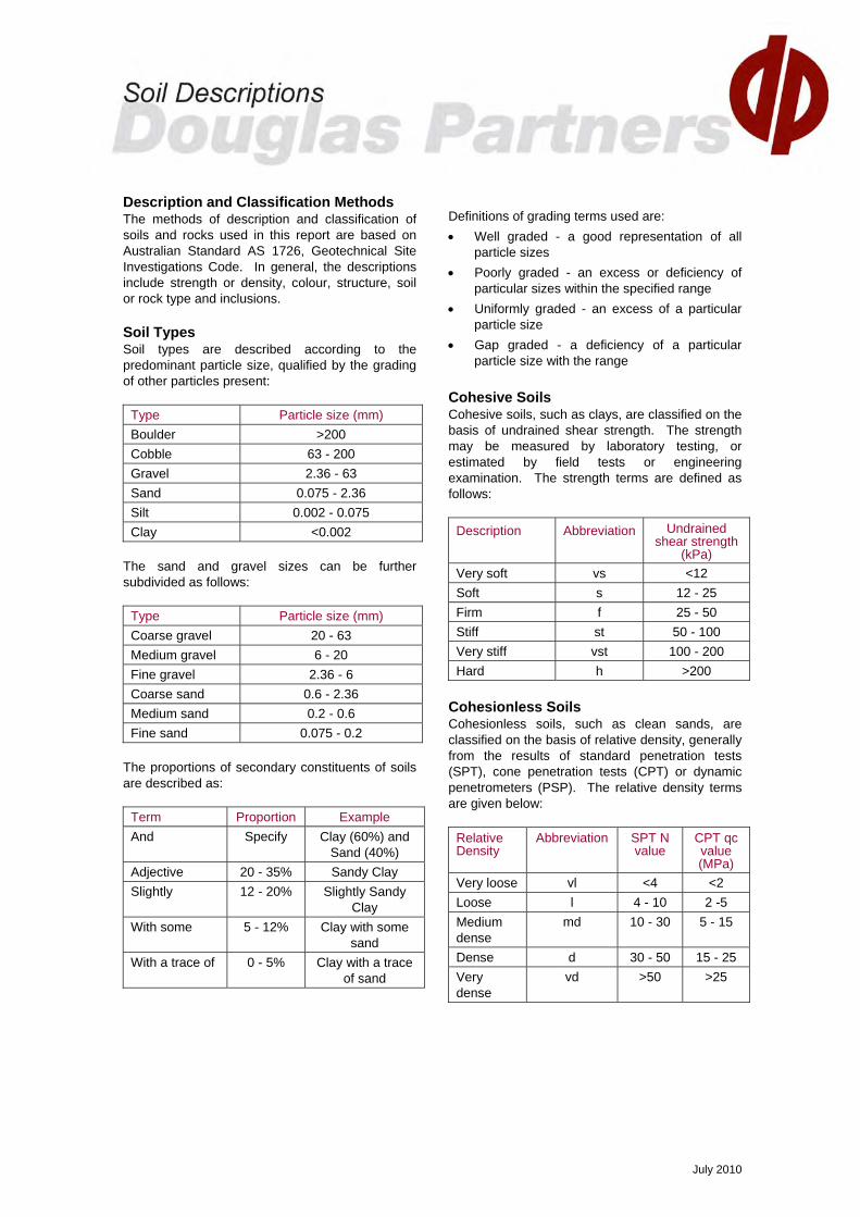
Description and Classification Methods The methods of description and classification of soils and rocks used in this report are based on Australian Standard AS 1726, Geotechnical Site Investigations Code. In general, the descriptions include strength or density, colour, structure, soil or rock type and inclusions. Soil Types Soil types are described according to the predominant particle size, qualified by the grading of other particles present:
Type Particle size (mm) Boulder >200 Cobble 63 - 200 Gravel 2.36 - 63 Sand 0.075 - 2.36 Silt 0.002 - 0.075 Clay <0.002
The sand and gravel sizes can be further subdivided as follows:
Type Particle size (mm) Coarse gravel 20 - 63 Medium gravel 6 - 20 Fine gravel 2.36 - 6 Coarse sand 0.6 - 2.36 Medium sand 0.2 - 0.6 Fine sand 0.075 - 0.2
The proportions of secondary constituents of soils are described as:
Term Proportion Example And Specify Clay (60%) and
Sand (40%) Adjective 20 - 35% Sandy Clay Slightly 12 - 20% Slightly Sandy
Clay With some 5 - 12% Clay with some
sand With a trace of 0 - 5% Clay with a trace
of sand
Definitions of grading terms used are: • Well graded - a good representation of all
particle sizes • Poorly graded - an excess or deficiency of
particular sizes within the specified range • Uniformly graded - an excess of a particular
particle size • Gap graded - a deficiency of a particular
particle size with the range Cohesive Soils Cohesive soils, such as clays, are classified on the basis of undrained shear strength. The strength may be measured by laboratory testing, or estimated by field tests or engineering examination. The strength terms are defined as follows:
Description Abbreviation Undrained shear strength
(kPa) Very soft vs <12 Soft s 12 - 25 Firm f 25 - 50 Stiff st 50 - 100 Very stiff vst 100 - 200 Hard h >200
Cohesionless Soils Cohesionless soils, such as clean sands, are classified on the basis of relative density, generally from the results of standard penetration tests (SPT), cone penetration tests (CPT) or dynamic penetrometers (PSP). The relative density terms are given below:
Relative Density
Abbreviation SPT N value
CPT qc value (MPa)
Very loose vl <4 <2 Loose l 4 - 10 2 -5 Medium dense
md 10 - 30 5 - 15
Dense d 30 - 50 15 - 25 Very dense
vd >50 >25

July 2010
Soil Origin It is often difficult to accurately determine the origin of a soil. Soils can generally be classified as: • Residual soil - derived from in-situ weathering
of the underlying rock; • Transported soils - formed somewhere else
and transported by nature to the site; or • Filling - moved by man. Transported soils may be further subdivided into: • Alluvium - river deposits • Lacustrine - lake deposits • Aeolian - wind deposits • Littoral - beach deposits • Estuarine - tidal river deposits • Talus - scree or coarse colluvium • Slopewash or Colluvium - transported
downslope by gravity assisted by water. Often includes angular rock fragments and boulders.

July 2010
Rock Strength Rock strength is defined by the Point Load Strength Index (Is(50)) and refers to the strength of the rock substance and not the strength of the overall rock mass, which may be considerably weaker due to defects. The test procedure is described by Australian Standard 4133.4.1 - 1993. The terms used to describe rock strength are as follows:
Term Abbreviation Point Load Index Is(50) MPa
Approx Unconfined Compressive Strength MPa*
Extremely low EL <0.03 <0.6
Very low VL 0.03 - 0.1 0.6 - 2
Low L 0.1 - 0.3 2 - 6
Medium M 0.3 - 1.0 6 - 20
High H 1 - 3 20 - 60
Very high VH 3 - 10 60 - 200
Extremely high EH >10 >200 * Assumes a ratio of 20:1 for UCS to Is(50)
Degree of Weathering The degree of weathering of rock is classified as follows:
Term Abbreviation Description Extremely weathered EW Rock substance has soil properties, i.e. it can be remoulded
and classified as a soil but the texture of the original rock is still evident.
Highly weathered HW Limonite staining or bleaching affects whole of rock substance and other signs of decomposition are evident. Porosity and strength may be altered as a result of iron leaching or deposition. Colour and strength of original fresh rock is not recognisable
Moderately weathered
MW Staining and discolouration of rock substance has taken place
Slightly weathered SW Rock substance is slightly discoloured but shows little or no change of strength from fresh rock
Fresh stained Fs Rock substance unaffected by weathering but staining visible along defects
Fresh Fr No signs of decomposition or staining Degree of Fracturing The following classification applies to the spacing of natural fractures in diamond drill cores. It includes bedding plane partings, joints and other defects, but excludes drilling breaks.
Term Description Fragmented Fragments of <20 mm Highly Fractured Core lengths of 20-40 mm with some fragments Fractured Core lengths of 40-200 mm with some shorter and longer sections Slightly Fractured Core lengths of 200-1000 mm with some shorter and loner sections Unbroken Core lengths mostly > 1000 mm

July 2010
Rock Quality Designation The quality of the cored rock can be measured using the Rock Quality Designation (RQD) index, defined as:
RQD % = cumulative length of 'sound' core sections ≥ 100 mm long total drilled length of section being assessed
where 'sound' rock is assessed to be rock of low strength or better. The RQD applies only to natural fractures. If the core is broken by drilling or handling (i.e. drilling breaks) then the broken pieces are fitted back together and are not included in the calculation of RQD. Stratification Spacing For sedimentary rocks the following terms may be used to describe the spacing of bedding partings:
Term Separation of Stratification Planes Thinly laminated < 6 mm Laminated 6 mm to 20 mm Very thinly bedded 20 mm to 60 mm Thinly bedded 60 mm to 0.2 m Medium bedded 0.2 m to 0.6 m Thickly bedded 0.6 m to 2 m Very thickly bedded > 2 m

July 2010
Introduction These notes summarise abbreviations commonly used on borehole logs and test pit reports. Drilling or Excavation Methods C Core Drilling R Rotary drilling SFA Spiral flight augers NMLC Diamond core - 52 mm dia NQ Diamond core - 47 mm dia HQ Diamond core - 63 mm dia PQ Diamond core - 81 mm dia Water
Water seep Water level
Sampling and Testing A Auger sample B Bulk sample D Disturbed sample E Environmental sample U50 Undisturbed tube sample (50mm) W Water sample pp pocket penetrometer (kPa) PID Photo ionisation detector PL Point load strength Is(50) MPa S Standard Penetration Test V Shear vane (kPa) Description of Defects in Rock The abbreviated descriptions of the defects should be in the following order: Depth, Type, Orientation, Coating, Shape, Roughness and Other. Drilling and handling breaks are not usually included on the logs. Defect Type B Bedding plane Cs Clay seam Cv Cleavage Cz Crushed zone Ds Decomposed seam F Fault J Joint Lam lamination Pt Parting Sz Sheared Zone V Vein
Orientation The inclination of defects is always measured from the perpendicular to the core axis. h horizontal v vertical sh sub-horizontal sv sub-vertical Coating or Infilling Term cln clean co coating he healed inf infilled stn stained ti tight vn veneer Coating Descriptor ca calcite cbs carbonaceous cly clay fe iron oxide mn manganese slt silty Shape cu curved ir irregular pl planar st stepped un undulating Roughness po polished ro rough sl slickensided sm smooth vr very rough Other fg fragmented bnd band qtz quartz

July 2010
Graphic Symbols for Soil and Rock General
Soils
Sedimentary Rocks
Metamorphic Rocks
Igneous Rocks
Road base
Filling
Concrete
Asphalt
Topsoil
Peat
Clay
Conglomeratic sandstone
Conglomerate
Boulder conglomerate
Sandstone
Slate, phyllite, schist
Siltstone
Mudstone, claystone, shale
Coal
Limestone
Porphyry
Cobbles, boulders
Sandy gravel
Laminite
Silty sand
Clayey sand
Silty clay
Sandy clay
Gravelly clay
Shaly clay
Silt
Clayey silt
Sandy silt
Sand
Gravel
Talus
Gneiss
Quartzite
Dolerite, basalt, andesite
Granite
Tuff, breccia
Dacite, epidote

Appendix B
Previous Cottier Borehole Logs (Bores BH05 – BH20) Previous DP Test Pit Logs (Pits 1 – 4)
Current Borehole Logs (Bores 101 – 112) Site Photographs
Drawing 1


BITUMINOUS CONCRETE - black, bituminous concrete,70 - 80% aggregate. Aggregate is fine to medium gravel(blue metal), <5% voids(WEARING COURSE)
FILLING - grey, slightly sandy, fine to medium gravel (bluemetal) with some clay, humid to damp(BASE)
FILLING - brown and grey, slightly clayey, fine to mediumgravel (blue metal, sandstone), humid to dampFILLING - grey, fine to coarse gravel (blue metal) withsome sand, humid(SUB-BASE)
CLAY - light brown grey mottled light to mid orangebrown, slightly gravelly (fine to medium siltstone) clay withsome silt, damp(RESIDUAL)- becoming humid to damp below 0.7m
SILTSTONE - low strength, moderately to slightlyweathered, orange brown to light grey siltstonePit discontinued at 1.05m(limit of investigation)
0.05
0.270.3
0.66
0.95
1.05
LOCATION:
4342
REMARKS:
WATER OBSERVATIONS: No free groundwater observed
TEST PIT LOG
Depth(m)
LOGGED: RJH
PIT No: 1PROJECT No: 48600.05DATE: 24/11/2010SHEET 1 OF 1
1 1
Results &Comments
Sampling & In Situ Testing
Wat
er
Dep
th
Sam
ple
Descriptionof
Strata Gra
phic
Log
Type
CLIENT:PROJECT:
SAMPLING & IN SITU TESTING LEGEND
Select Civil Pty LtdDamaged Pavements
RL
RIG: Hitachi 294 with 300mm / 1200mm bucket
Test Pit Photo 1
Damp for top 50mm of residual clay
Nowra Correctional CentreOxford Road, South Nowra
SURVEY DATUM: MGA94
A Auger sample G Gas sample PID Photo ionisation detector (ppm)B Bulk sample P Piston sample PL(A) Point load axial test Is(50) (MPa)BLK Block sample Ux Tube sample (x mm dia.) PL(D) Point load diametral test Is(50) (MPa)C Core drilling W Water sample pp Pocket penetrometer (kPa)D Disturbed sample Water seep S Standard penetration testE Environmental sample Water level V Shear vane (kPa)
SURFACE LEVEL: 43.0 AHDEASTING:NORTHING:DIP/AZIMUTH: 90°/--
5 10 15 20
Sand Penetrometer AS1289.6.3.3 Cone Penetrometer AS1289.6.3.2
Dynamic Penetrometer Test(blows per 150mm)
D
B
D
B
B
B
0.00.05
0.250.270.3
0.5
0.7
0.90.95
1.05

BITUMINOUS CONCRETE - black, bituminous concrete,60 - 80% aggregate. Aggregate is fine to medium gravel(blue metal), >3% voids(WEARING COURSE)
FILLING - grey, fine to medium gravel (blue metal) withsome sand, silt and trace clay, humid to damp(BASE)
FILLING - grey, slightly sandy, fine to coarse gravel (bluemetal), humid to damp(SUB-BASE)
CLAY - red brown clay with some silt and trace rootlets,damp(RESIDUAL)
SILTSTONE - low to medium strength, moderately toslightly weathered, orange brown to grey siltstonePit discontinued at 0.6m(limit of investigation)
0.025
0.175
0.4
0.5
0.6
LOCATION:
44
REMARKS:
WATER OBSERVATIONS: No free groundwater observed
TEST PIT LOG
Depth(m)
LOGGED: RJH
PIT No: 2PROJECT No: 48600.05DATE: 24/11/2010SHEET 1 OF 1
Results &Comments
Sampling & In Situ Testing
Wat
er
Dep
th
Sam
ple
Descriptionof
Strata Gra
phic
Log
Type
CLIENT:PROJECT:
SAMPLING & IN SITU TESTING LEGEND
Select Civil Pty LtdDamaged Pavements
RL
RIG: Hitachi 294 with 300mm / 1200mm bucket
Test Pit Photo 2
Nowra Correctional CentreOxford Road, South Nowra
SURVEY DATUM: MGA94
A Auger sample G Gas sample PID Photo ionisation detector (ppm)B Bulk sample P Piston sample PL(A) Point load axial test Is(50) (MPa)BLK Block sample Ux Tube sample (x mm dia.) PL(D) Point load diametral test Is(50) (MPa)C Core drilling W Water sample pp Pocket penetrometer (kPa)D Disturbed sample Water seep S Standard penetration testE Environmental sample Water level V Shear vane (kPa)
SURFACE LEVEL: 44.3 AHDEASTING:NORTHING:DIP/AZIMUTH: 90°/--
5 10 15 20
Sand Penetrometer AS1289.6.3.3 Cone Penetrometer AS1289.6.3.2
Dynamic Penetrometer Test(blows per 150mm)
B
B
D
B
0.1
0.3
0.4
0.5
0.6

BITUMINOUS CONCRETE - black, bituminous concrete,60 - 80% aggregate. Aggregate is fine to medium gravel(blue metal), <3% voids(WEARING COURSE)
FILLING - grey, slightly sandy, fine to medium gravel (bluemetal) with some clay and silt, humid to damp(BASE)
FILLING - grey, fine to coarse gravel (blue metal) withsome sand and silt, humid to damp(SUB-BASE)
CLAY - stiff, red brown mottled light grey, fissured, slightlysilty clay with trace rootlets, damp(RESIDUAL)
SILTSTONE - low to medium strength, highly to slightlyweathered, red brown to grey siltstonePit discontinued at 0.75m(limit of investigation)
0.03
0.15
0.35
0.55
0.75
LOCATION:
REMARKS:
WATER OBSERVATIONS: No free groundwater observed
TEST PIT LOG
Depth(m)
LOGGED: RJH
PIT No: 3PROJECT No: 48600.05DATE: 24/11/2010SHEET 1 OF 1
Results &Comments
Sampling & In Situ Testing
Wat
er
Dep
th
Sam
ple
Descriptionof
Strata Gra
phic
Log
Type
CLIENT:PROJECT:
SAMPLING & IN SITU TESTING LEGEND
Select Civil Pty LtdDamaged Pavements
RL
RIG: Hitachi 294 with 300mm / 1200mm bucket
Test Pit Photo 3
Nowra Correctional CentreOxford Road, South Nowra
SURVEY DATUM: MGA94
A Auger sample G Gas sample PID Photo ionisation detector (ppm)B Bulk sample P Piston sample PL(A) Point load axial test Is(50) (MPa)BLK Block sample Ux Tube sample (x mm dia.) PL(D) Point load diametral test Is(50) (MPa)C Core drilling W Water sample pp Pocket penetrometer (kPa)D Disturbed sample Water seep S Standard penetration testE Environmental sample Water level V Shear vane (kPa)
SURFACE LEVEL: 44.8 AHDEASTING:NORTHING:DIP/AZIMUTH: 90°/--
5 10 15 20
Sand Penetrometer AS1289.6.3.3 Cone Penetrometer AS1289.6.3.2
Dynamic Penetrometer Test(blows per 150mm)
B
B
B
B
0.05
0.150.2
0.30.35
0.55
0.75
pp = 310 - 320kPa
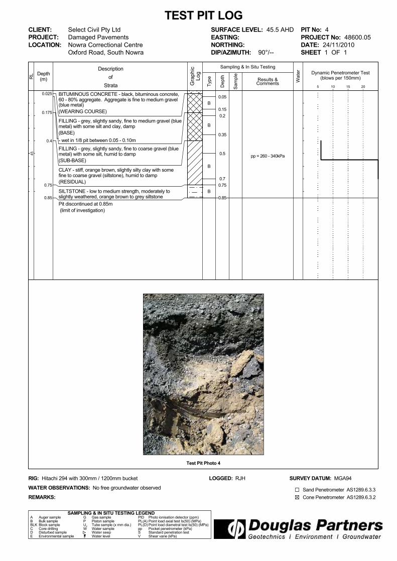
BITUMINOUS CONCRETE - black, bituminous concrete,60 - 80% aggregate. Aggregate is fine to medium gravel(blue metal)(WEARING COURSE)
FILLING - grey, slightly sandy, fine to medium gravel (bluemetal) with some silt and clay, damp(BASE)- wet in 1/8 pit between 0.05 - 0.10mFILLING - grey, slightly sandy, fine to coarse gravel (bluemetal) with some silt, humid to damp(SUB-BASE)
CLAY - stiff, orange brown, slightly silty clay with somefine to coarse gravel (siltstone), humid to damp(RESIDUAL)
SILTSTONE - low to medium strength, moderately toslightly weathered, orange brown to grey siltstonePit discontinued at 0.85m(limit of investigation)
0.025
0.175
0.4
0.75
0.85
LOCATION:
45
REMARKS:
WATER OBSERVATIONS: No free groundwater observed
TEST PIT LOG
Depth(m)
LOGGED: RJH
PIT No: 4PROJECT No: 48600.05DATE: 24/11/2010SHEET 1 OF 1
Results &Comments
Sampling & In Situ Testing
Wat
er
Dep
th
Sam
ple
Descriptionof
Strata Gra
phic
Log
Type
CLIENT:PROJECT:
SAMPLING & IN SITU TESTING LEGEND
Select Civil Pty LtdDamaged Pavements
RL
RIG: Hitachi 294 with 300mm / 1200mm bucket
Test Pit Photo 4
Nowra Correctional CentreOxford Road, South Nowra
SURVEY DATUM: MGA94
A Auger sample G Gas sample PID Photo ionisation detector (ppm)B Bulk sample P Piston sample PL(A) Point load axial test Is(50) (MPa)BLK Block sample Ux Tube sample (x mm dia.) PL(D) Point load diametral test Is(50) (MPa)C Core drilling W Water sample pp Pocket penetrometer (kPa)D Disturbed sample Water seep S Standard penetration testE Environmental sample Water level V Shear vane (kPa)
SURFACE LEVEL: 45.5 AHDEASTING:NORTHING:DIP/AZIMUTH: 90°/--
5 10 15 20
Sand Penetrometer AS1289.6.3.3 Cone Penetrometer AS1289.6.3.2
Dynamic Penetrometer Test(blows per 150mm)
B
B
B
B
0.05
0.150.2
0.35
0.5
0.70.75
0.85
pp = 260 - 340kPa

FILLING - grey brown, slightly silty, gravelly clay, humid
CLAY - brown grey, slightly silty clay
SILTY CLAY - grey, silty clay, damp
- pink mottled below 2.5m
Pit discontinued at 3.0m(Refusal on low to medium strength shale)
0.9
1.2
3.0
SAMPLING & IN SITU TESTING LEGEND
1
2
3
RL
5453
5251
TEST PIT LOG
Depth(m)
55 The Links Road, South Nowra
A Auger sample G Gas sample PID Photo ionisation detector (ppm)B Bulk sample P Piston sample PL(A) Point load axial test Is(50) (MPa)BLK Block sample Ux Tube sample (x mm dia.) PL(D) Point load diametral test Is(50) (MPa)C Core drilling W Water sample pp Pocket penetrometer (kPa)D Disturbed sample Water seep S Standard penetration testE Environmental sample Water level V Shear vane (kPa)
Guymer Bailey ArchitectsProposed Correctional Centre Upgrade
Results &Comments
LOGGED: CMcD SURVEY DATUM: MGA94 Zone 56
CLIENT:PROJECT:LOCATION:
PIT No: 101PROJECT No: 48600.06DATE: 27/5/2016SHEET 1 OF 1
Sampling & In Situ Testing
1
2
3
Wat
er
Dep
th
Sam
ple
Description
of
Strata Gra
phic
Log
Typ
e
REMARKS:
RIG: Kubota KX018-4
WATER OBSERVATIONS: No free groundwater observed
SURFACE LEVEL: 54.8 AHDEASTING: 280380NORTHING: 6133107
Dynamic Penetrometer Test(blows per 150mm)
5 10 15 20
Cone Penetrometer AS1289.6.3.2Sand Penetrometer AS1289.6.3.3
D
DE
DE
0.1
0.5
1.5
BD2

FILLING - brown grey, slightly silty, slightly gravelly, clay,damp
CLAY - stiff to very stiff, red brown mottled grey, slightlysilty, clay, damp
SILTY CLAY - stiff to very stiff, grey, slightly sandy, siltyclay, damp
SHALE - extremely low to very low strength, highlyweathered, grey, shale
Pit discontinued at 2.0m(Refusal on low to medium strength shale)
0.5
1.1
1.5
2.0
SAMPLING & IN SITU TESTING LEGEND
1
2
3
RL
5352
5150
TEST PIT LOG
Depth(m)
55 The Links Road, South Nowra
A Auger sample G Gas sample PID Photo ionisation detector (ppm)B Bulk sample P Piston sample PL(A) Point load axial test Is(50) (MPa)BLK Block sample Ux Tube sample (x mm dia.) PL(D) Point load diametral test Is(50) (MPa)C Core drilling W Water sample pp Pocket penetrometer (kPa)D Disturbed sample Water seep S Standard penetration testE Environmental sample Water level V Shear vane (kPa)
Guymer Bailey ArchitectsProposed Correctional Centre Upgrade
Results &Comments
LOGGED: CMcD SURVEY DATUM: MGA94 Zone 56
CLIENT:PROJECT:LOCATION:
PIT No: 102PROJECT No: 48600.06DATE: 27/5/2016SHEET 1 OF 1
Sampling & In Situ Testing
1
2
3
Wat
er
Dep
th
Sam
ple
Description
of
Strata Gra
phic
Log
Typ
e
REMARKS:
RIG: Kubota KX018-4
WATER OBSERVATIONS: No free groundwater observed
SURFACE LEVEL: 53.6 AHDEASTING: 280462NORTHING: 6133136
Dynamic Penetrometer Test(blows per 150mm)
5 10 15 20
Cone Penetrometer AS1289.6.3.2Sand Penetrometer AS1289.6.3.3
D
U
D
D
D
0.5
0.9
1.0
1.5
2.0
pp = 300-350
pp = 200-230
pp = 150-240

FILLING - brown grey, slightly silty, gravelly clay, humid
- slow progess at 0.8m
Pit discontinued at 1.0m(Refusal in gravelly filling)
1.0
SAMPLING & IN SITU TESTING LEGEND
1
2
3
RL
5554
5352
TEST PIT LOG
Depth(m)
55 The Links Road, South Nowra
A Auger sample G Gas sample PID Photo ionisation detector (ppm)B Bulk sample P Piston sample PL(A) Point load axial test Is(50) (MPa)BLK Block sample Ux Tube sample (x mm dia.) PL(D) Point load diametral test Is(50) (MPa)C Core drilling W Water sample pp Pocket penetrometer (kPa)D Disturbed sample Water seep S Standard penetration testE Environmental sample Water level V Shear vane (kPa)
Guymer Bailey ArchitectsProposed Correctional Centre Upgrade
Results &Comments
LOGGED: CMcD SURVEY DATUM: MGA94 Zone 56
CLIENT:PROJECT:LOCATION:
PIT No: 103PROJECT No: 48600.06DATE: 27/5/2016SHEET 1 OF 1
Sampling & In Situ Testing
1
2
3
Wat
er
Dep
th
Sam
ple
Description
of
Strata Gra
phic
Log
Typ
e
REMARKS:
RIG: Kubota KX018-4
WATER OBSERVATIONS: No free groundwater observed
SURFACE LEVEL: 55.5 AHDEASTING: 280461NORTHING: 6133068
Dynamic Penetrometer Test(blows per mm)
5 10 15 20
Cone Penetrometer AS1289.6.3.2Sand Penetrometer AS1289.6.3.3
D
D
0.5
1.0
pp = 390-400

SILTY CLAY - very stiff, friable, silty clay with some sand,humid
- gravelly below 1.0m
SHALE - extremely low to very low strength, highlyweathered, light grey, shale
- very low to low strength below 1.6m
Pit discontinued at 2.0m(Refusal on low to medium strength shale)
1.2
2.0
SAMPLING & IN SITU TESTING LEGEND
1
2
3
RL
5352
5150
TEST PIT LOG
Depth(m)
55 The Links Road, South Nowra
A Auger sample G Gas sample PID Photo ionisation detector (ppm)B Bulk sample P Piston sample PL(A) Point load axial test Is(50) (MPa)BLK Block sample Ux Tube sample (x mm dia.) PL(D) Point load diametral test Is(50) (MPa)C Core drilling W Water sample pp Pocket penetrometer (kPa)D Disturbed sample Water seep S Standard penetration testE Environmental sample Water level V Shear vane (kPa)
Guymer Bailey ArchitectsProposed Correctional Centre Upgrade
Results &Comments
LOGGED: CMcD SURVEY DATUM: MGA94 Zone 56
CLIENT:PROJECT:LOCATION:
PIT No: 104PROJECT No: 48600.06DATE: 27/5/2016SHEET 1 OF 1
Sampling & In Situ Testing
1
2
3
Wat
er
Dep
th
Sam
ple
Description
of
Strata Gra
phic
Log
Typ
e
REMARKS:
RIG: Kubota KX018-4
WATER OBSERVATIONS: No free groundwater observed
SURFACE LEVEL: 53.8 AHDEASTING: 280699NORTHING: 6133047
Dynamic Penetrometer Test(blows per 150mm)
5 10 15 20
Cone Penetrometer AS1289.6.3.2Sand Penetrometer AS1289.6.3.3
E
DE
U
D
D
0.1
0.5
0.9
1.0
1.5

FILLING - brown grey, fine to medium clayey silty gravel,humid
SILTY CLAY - very stiff to hard, orange brown mottledgrey, silty clay, damp
Pit discontinued at 2.8m(Refusal on low strength shale)
1.0
2.8
SAMPLING & IN SITU TESTING LEGEND
1
2
3
RL
5756
5554
TEST PIT LOG
Depth(m)
55 The Links Road, South Nowra
A Auger sample G Gas sample PID Photo ionisation detector (ppm)B Bulk sample P Piston sample PL(A) Point load axial test Is(50) (MPa)BLK Block sample Ux Tube sample (x mm dia.) PL(D) Point load diametral test Is(50) (MPa)C Core drilling W Water sample pp Pocket penetrometer (kPa)D Disturbed sample Water seep S Standard penetration testE Environmental sample Water level V Shear vane (kPa)
Guymer Bailey ArchitectsProposed Correctional Centre Upgrade
Results &Comments
LOGGED: CMcD SURVEY DATUM: MGA94 Zone 56
CLIENT:PROJECT:LOCATION:
PIT No: 105PROJECT No: 48600.06DATE: 27/5/2016SHEET 1 OF 1
Sampling & In Situ Testing
1
2
3
Wat
er
Dep
th
Sam
ple
Description
of
Strata Gra
phic
Log
Typ
e
REMARKS:
RIG: Kubota KX018-4
WATER OBSERVATIONS: No free groundwater observed
SURFACE LEVEL: 57.3 AHDEASTING: 280353NORTHING: 6132889
Dynamic Penetrometer Test(blows per 150mm)
5 10 15 20
Cone Penetrometer AS1289.6.3.2Sand Penetrometer AS1289.6.3.3
D
D
D
D
D
0.5
1.0
1.5
2.0
2.5
pp = 190-220
pp = 190-250

TOPSOIL - brown grey, slightly silty gravelly clay, humid
GRAVELLY SILTY CLAY - orange brown, gravelly siltyclay, humid
- slow progress at 0.5m
Pit discontinued at 0.7m(Refusal on low strength shale)
0.05
0.7
SAMPLING & IN SITU TESTING LEGEND
1
2
3
RL
5958
5756
TEST PIT LOG
Depth(m)
55 The Links Road, South Nowra
A Auger sample G Gas sample PID Photo ionisation detector (ppm)B Bulk sample P Piston sample PL(A) Point load axial test Is(50) (MPa)BLK Block sample Ux Tube sample (x mm dia.) PL(D) Point load diametral test Is(50) (MPa)C Core drilling W Water sample pp Pocket penetrometer (kPa)D Disturbed sample Water seep S Standard penetration testE Environmental sample Water level V Shear vane (kPa)
Guymer Bailey ArchitectsProposed Correctional Centre Upgrade
Results &Comments
LOGGED: CMcD SURVEY DATUM: MGA94 Zone 56
CLIENT:PROJECT:LOCATION:
PIT No: 106PROJECT No: 48600.06DATE: 27/5/2016SHEET 1 OF 1
Sampling & In Situ Testing
1
2
3
Wat
er
Dep
th
Sam
ple
Description
of
Strata Gra
phic
Log
Typ
e
REMARKS:
RIG: Kubota KX018-4
WATER OBSERVATIONS: No free groundwater observed
SURFACE LEVEL: 59.1 AHDEASTING: 280437NORTHING: 6132874
Dynamic Penetrometer Test(blows per mm)
5 10 15 20
Cone Penetrometer AS1289.6.3.2Sand Penetrometer AS1289.6.3.3
E
DE
0.1
0.5

FILLING - dark grey, slightly silty, fine to medium clayeygravel (sandstone), humid
GRAVELLY SILTY CLAY - orange brown, gravelly siltyclay, humid
- slow progress below 0.4m
Pit discontinued at 0.5m(Refusal on low strength shale)
0.1
0.5
SAMPLING & IN SITU TESTING LEGEND
1
2
3
RL
6059
5857
TEST PIT LOG
Depth(m)
55 The Links Road, South Nowra
A Auger sample G Gas sample PID Photo ionisation detector (ppm)B Bulk sample P Piston sample PL(A) Point load axial test Is(50) (MPa)BLK Block sample Ux Tube sample (x mm dia.) PL(D) Point load diametral test Is(50) (MPa)C Core drilling W Water sample pp Pocket penetrometer (kPa)D Disturbed sample Water seep S Standard penetration testE Environmental sample Water level V Shear vane (kPa)
Guymer Bailey ArchitectsProposed Correctional Centre Upgrade
Results &Comments
LOGGED: CMcD SURVEY DATUM: MGA94 Zone 56
CLIENT:PROJECT:LOCATION:
PIT No: 107PROJECT No: 48600.06DATE: 27/5/2016SHEET 1 OF 1
Sampling & In Situ Testing
1
2
3
Wat
er
Dep
th
Sam
ple
Description
of
Strata Gra
phic
Log
Typ
e
REMARKS:
RIG: Kubota KX018-4
WATER OBSERVATIONS: No free groundwater observed
SURFACE LEVEL: 60.8 AHDEASTING: 280489NORTHING: 6132863
Dynamic Penetrometer Test(blows per mm)
5 10 15 20
Cone Penetrometer AS1289.6.3.2Sand Penetrometer AS1289.6.3.3
D 0.5

FILLING - slightly clayey, brown grey, slightly silty, fine tomedium sandy gravel (sandstone), humid
- clayey below 1.0m
- slow progress at 2.8m
Pit discontinued at 3.0m(Limit of investigation)
3.0
SAMPLING & IN SITU TESTING LEGEND
1
2
3
RL
5857
5655
TEST PIT LOG
Depth(m)
55 The Links Road, South Nowra
A Auger sample G Gas sample PID Photo ionisation detector (ppm)B Bulk sample P Piston sample PL(A) Point load axial test Is(50) (MPa)BLK Block sample Ux Tube sample (x mm dia.) PL(D) Point load diametral test Is(50) (MPa)C Core drilling W Water sample pp Pocket penetrometer (kPa)D Disturbed sample Water seep S Standard penetration testE Environmental sample Water level V Shear vane (kPa)
Guymer Bailey ArchitectsProposed Correctional Centre Upgrade
Results &Comments
LOGGED: CMcD SURVEY DATUM: MGA94 Zone 56
CLIENT:PROJECT:LOCATION:
PIT No: 108PROJECT No: 48600.06DATE: 27/5/2016SHEET 1 OF 1
Sampling & In Situ Testing
1
2
3
Wat
er
Dep
th
Sam
ple
Description
of
Strata Gra
phic
Log
Typ
e
REMARKS:
RIG: Kubota KX018-4
WATER OBSERVATIONS: No free groundwater observed
SURFACE LEVEL: 58.7 AHDEASTING: 280680NORTHING: 6132812
Dynamic Penetrometer Test(blows per mm)
5 10 15 20
Cone Penetrometer AS1289.6.3.2Sand Penetrometer AS1289.6.3.3
DE
DE
D
DE
E
DE
0.1
0.5
1.0
1.5
2.0
2.5
FILLING - brown grey, slightly silty, gravelly clay, humid
SILTY CLAY - stiff, light brown grey mottled dark grey,silty clay, damp to moist
- slightly gravelly below 2.0m
SHALE - extremely low to low strength, highly weathered,grey shale with some silty clay bands
Pit discontinued at 2.6m(Refusal on low to medium strength shale)
0.8
2.2
2.6
SAMPLING & IN SITU TESTING LEGEND
1
2
3
RL
6261
6059
TEST PIT LOG
Depth(m)
55 The Links Road, South Nowra
A Auger sample G Gas sample PID Photo ionisation detector (ppm)B Bulk sample P Piston sample PL(A) Point load axial test Is(50) (MPa)BLK Block sample Ux Tube sample (x mm dia.) PL(D) Point load diametral test Is(50) (MPa)C Core drilling W Water sample pp Pocket penetrometer (kPa)D Disturbed sample Water seep S Standard penetration testE Environmental sample Water level V Shear vane (kPa)
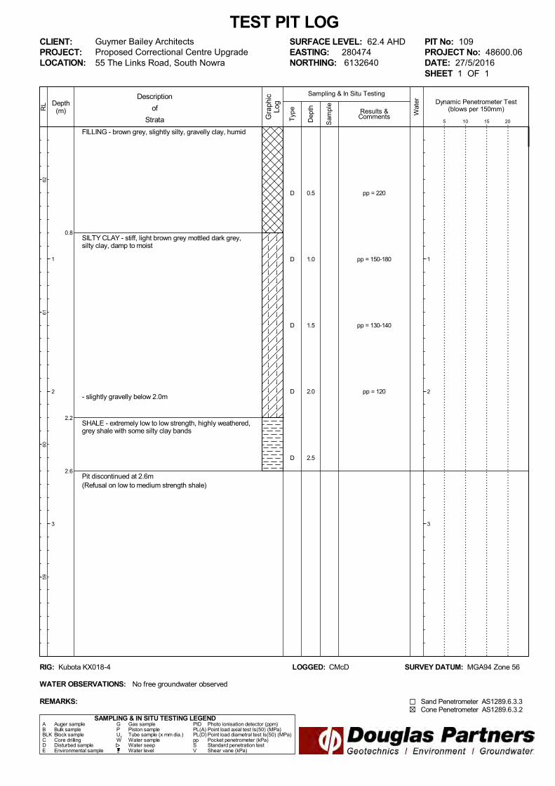
Guymer Bailey ArchitectsProposed Correctional Centre Upgrade
Results &Comments
LOGGED: CMcD SURVEY DATUM: MGA94 Zone 56
CLIENT:PROJECT:LOCATION:
PIT No: 109PROJECT No: 48600.06DATE: 27/5/2016SHEET 1 OF 1
Sampling & In Situ Testing
1
2
3
Wat
er
Dep
th
Sam
ple
Description
of
Strata Gra
phic
Log
Typ
e
REMARKS:
RIG: Kubota KX018-4
WATER OBSERVATIONS: No free groundwater observed
SURFACE LEVEL: 62.4 AHDEASTING: 280474NORTHING: 6132640
Dynamic Penetrometer Test(blows per 150mm)
5 10 15 20
Cone Penetrometer AS1289.6.3.2Sand Penetrometer AS1289.6.3.3
D
D
D
D
D
0.5
1.0
1.5
2.0
2.5
pp = 220
pp = 150-180
pp = 130-140
pp = 120
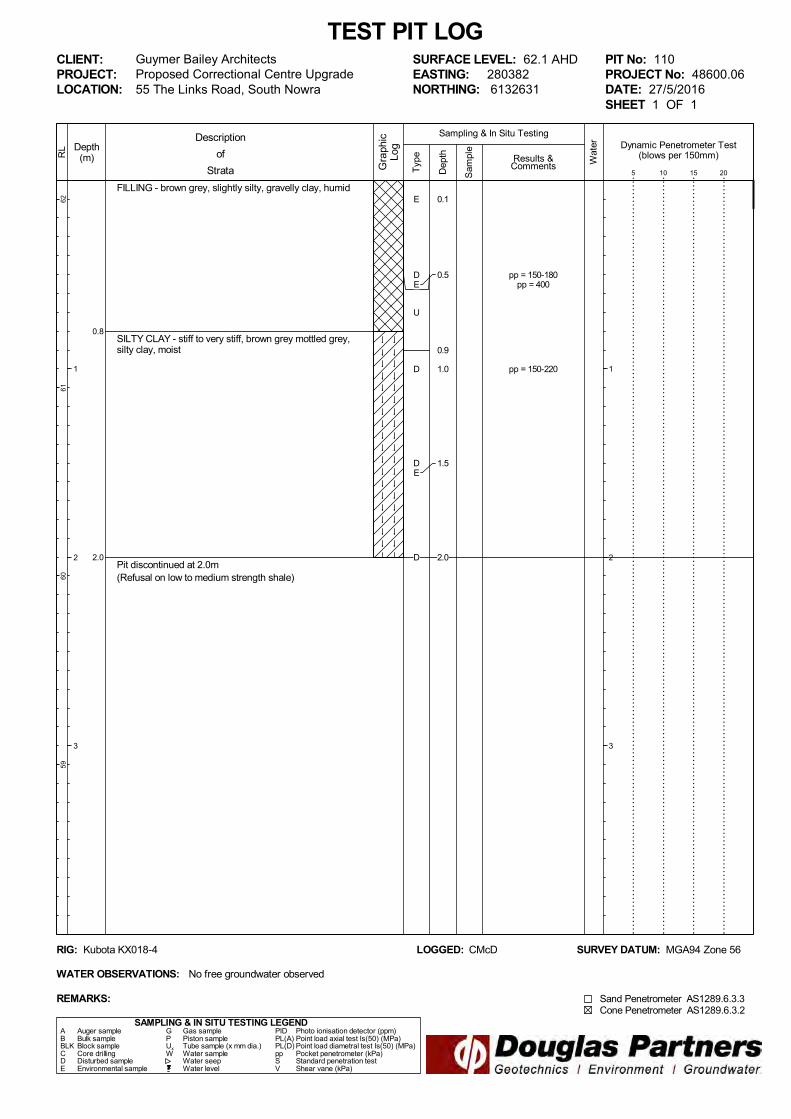
FILLING - brown grey, slightly silty, gravelly clay, humid
SILTY CLAY - stiff to very stiff, brown grey mottled grey,silty clay, moist
Pit discontinued at 2.0m(Refusal on low to medium strength shale)
0.8
2.0
SAMPLING & IN SITU TESTING LEGEND
1
2
3
RL
6261
6059
TEST PIT LOG
Depth(m)
55 The Links Road, South Nowra
A Auger sample G Gas sample PID Photo ionisation detector (ppm)B Bulk sample P Piston sample PL(A) Point load axial test Is(50) (MPa)BLK Block sample Ux Tube sample (x mm dia.) PL(D) Point load diametral test Is(50) (MPa)C Core drilling W Water sample pp Pocket penetrometer (kPa)D Disturbed sample Water seep S Standard penetration testE Environmental sample Water level V Shear vane (kPa)
Guymer Bailey ArchitectsProposed Correctional Centre Upgrade
Results &Comments
LOGGED: CMcD SURVEY DATUM: MGA94 Zone 56
CLIENT:PROJECT:LOCATION:
PIT No: 110PROJECT No: 48600.06DATE: 27/5/2016SHEET 1 OF 1
Sampling & In Situ Testing
1
2
3
Wat
er
Dep
th
Sam
ple
Description
of
Strata Gra
phic
Log
Typ
e
REMARKS:
RIG: Kubota KX018-4
WATER OBSERVATIONS: No free groundwater observed
SURFACE LEVEL: 62.1 AHDEASTING: 280382NORTHING: 6132631
Dynamic Penetrometer Test(blows per 150mm)
5 10 15 20
Cone Penetrometer AS1289.6.3.2Sand Penetrometer AS1289.6.3.3
E
DE
U
D
DE
D
0.1
0.5
0.9
1.0
1.5
2.0
pp = 150-180pp = 400
pp = 150-220

FILLING - brown grey, slightly silty, gravelly clay, humid
SILTY CLAY - brown mottled grey, silty clay, damp
SHALE - extremely low to very low strength, highlyweathered, grey, shale
Pit discontinued at 2.1m(Refusal on low to medium strength shale)
0.8
1.8
2.1
SAMPLING & IN SITU TESTING LEGEND
1
2
3
RL
6261
6059
TEST PIT LOG
Depth(m)
55 The Links Road, South Nowra
A Auger sample G Gas sample PID Photo ionisation detector (ppm)B Bulk sample P Piston sample PL(A) Point load axial test Is(50) (MPa)BLK Block sample Ux Tube sample (x mm dia.) PL(D) Point load diametral test Is(50) (MPa)C Core drilling W Water sample pp Pocket penetrometer (kPa)D Disturbed sample Water seep S Standard penetration testE Environmental sample Water level V Shear vane (kPa)
Guymer Bailey ArchitectsProposed Correctional Centre Upgrade
Results &Comments
LOGGED: CMcD SURVEY DATUM: MGA94 Zone 56
CLIENT:PROJECT:LOCATION:
PIT No: 111PROJECT No: 48600.06DATE: 27/5/2016SHEET 1 OF 1
Sampling & In Situ Testing
1
2
3
Wat
er
Dep
th
Sam
ple
Description
of
Strata Gra
phic
Log
Typ
e
REMARKS:
RIG: Kubota KX018-4
WATER OBSERVATIONS: No free groundwater observed
SURFACE LEVEL: 62.2 AHDEASTING: 280480NORTHING: 6132616
Dynamic Penetrometer Test(blows per 150mm)
5 10 15 20
Cone Penetrometer AS1289.6.3.2Sand Penetrometer AS1289.6.3.3
D
D
D
D
0.5
1.0
1.5
2.0
pp = 160-200
pp = 120-150

FILLING - grey brown, slightly silty, slightly sandy,gravelly clay
SILTY CLAY - firm to stiff, light brown grey, silty clay withsome gravel (ironstone), damp
- moist to wet below 1.0m
SHALE - extremely low to very low strength, highlyweathered grey, shale with some silty clay bands
Pit discontinued at 1.6m(Refusal on low to medium strength shale)
0.2
1.3
1.6
SAMPLING & IN SITU TESTING LEGEND
1
2
3
RL
5857
5655
TEST PIT LOG
Depth(m)
55 The Links Road, South Nowra
A Auger sample G Gas sample PID Photo ionisation detector (ppm)B Bulk sample P Piston sample PL(A) Point load axial test Is(50) (MPa)BLK Block sample Ux Tube sample (x mm dia.) PL(D) Point load diametral test Is(50) (MPa)C Core drilling W Water sample pp Pocket penetrometer (kPa)D Disturbed sample Water seep S Standard penetration testE Environmental sample Water level V Shear vane (kPa)
Guymer Bailey ArchitectsProposed Correctional Centre Upgrade
Results &Comments
LOGGED: CMcD SURVEY DATUM: MGA94 Zone 56
CLIENT:PROJECT:LOCATION:
PIT No: 112PROJECT No: 48600.06DATE: 27/5/2016SHEET 1 OF 1
Sampling & In Situ Testing
1
2
3
Wat
er
Dep
th
Sam
ple
Description
of
Strata Gra
phic
Log
Typ
e
REMARKS:
RIG: Kubota KX018-4
WATER OBSERVATIONS: No free groundwater observed
SURFACE LEVEL: 58.4 AHDEASTING: 280609NORTHING: 6132576
Dynamic Penetrometer Test(blows per 150mm)
5 10 15 20
Cone Penetrometer AS1289.6.3.2Sand Penetrometer AS1289.6.3.3
E
DE
U
D
D
0.1
0.5
0.9
1.0
1.5
pp = 160-200pp = 110-130
pp = 180-230

Site Photographs PROJECT: 48600.06
Proposed Correctional Centre Upgrade PLATE No: 1
55 The Links Road, South Nowra REV: 0
CLIENT: Guymer Bailey Architects DATE: 17 Jun 2016
Photo1 – Drilling of Bore 102
Photo 2 – Rear of correctional centre
Site Photographs PROJECT: 48600.06
Proposed Correctional Centre Upgrade PLATE No: 2
55 The Links Road, South Nowra REV: 0
CLIENT: Guymer Bailey Architects DATE: 17 Jun 2016
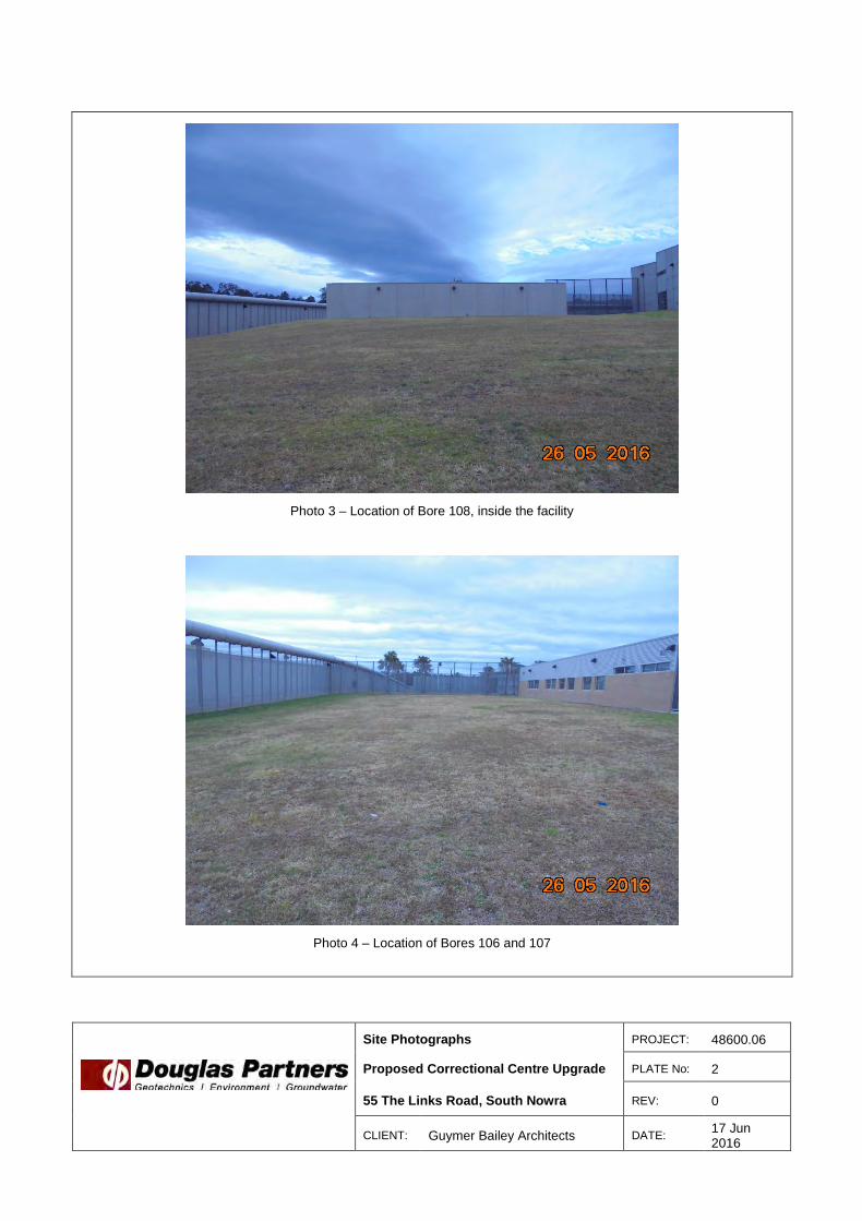
Photo 3 – Location of Bore 108, inside the facility
Photo 4 – Location of Bores 106 and 107

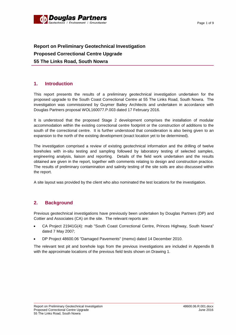
Site Photographs PROJECT: 48600.06
Proposed Correctional Centre Upgrade PLATE No: 3
55 The Links Road, South Nowra REV: 0
CLIENT: Guymer Bailey Architects DATE: 17 Jun 2016
Photo 5 – Gravelly silty clay and sandstone in Bore 107
Photo 6 – Spoil generated by Bore 107


Appendix C
Results of Laboratory Tests


Appendix D
Table D1: Contamination Laboratory Summary Table Laboratory Certificate of Analysis, Sample Receipt Advice and
Chain of Custody Documentation
Report on Preliminary Geotechnical Investigation - Proposed Correctional Centre Upgrades55 The Links Road, South Nowra
Project 48600.06June 2016
OPP
As Cd Cr Cu Pb Hg Ni Zn F1 F2 F3 F4 Benzene Toluene Ethyl benzene
Total Xylene
Total PAH
B(a)P TEQ B(a)P Napthalene Aldrin +
Dieldrin Chlordane DDT + DDD + DDE Endosulfan Endrin Heptachlor HCB Methoxychlor Chlorpyrifos
PQL <4 <0.4 <1 <1 <1 <0.1 <1 <1 <25 <50 <100 <100 <0.2 <0.5 <1 <3 <1.55 <0.5 <0.05 <0.1 <5 <0.7 <0.2 <0.2 <0.3 <0.1 <0.1 <0.2 <0.1 <0.1 <0.2 NAD101/0.1 6 <0.4 12 20 8 <0.1 5 21 <25 <50 <100 <100 <0.2 <0.5 <1 <3 <1.55 <0.5 <0.05 <0.1 <5 <0.7 <0.2 <0.2 <0.3 <0.1 <0.1 <0.2 <0.1 <0.1 <0.2 NAD108/0.1 6 <0.4 12 16 10 <0.1 4 18 <25 <50 <100 <100 <0.2 <0.5 <1 <3 <1.55 <0.5 <0.05 <0.1 <5 <0.7 <0.2 <0.2 <0.3 <0.1 <0.1 <0.2 <0.1 <0.1 <0.2 NAD110/0.1 7 <0.4 14 17 7 <0.1 2 10 <25 <50 <100 <100 <0.2 <0.5 <1 <3 <1.55 <0.5 <0.05 <0.1 <5 <0.7 <0.2 <0.2 <0.3 <0.1 <0.1 <0.2 <0.1 <0.1 <0.2 NAD112/0.5 8 <0.4 16 25 10 <0.1 6 34 <25 <50 <100 <100 <0.2 <0.5 <1 <3 <1.55 <0.5 <0.05 <0.1 <5 <0.7 <0.2 <0.2 <0.3 <0.1 <0.1 <0.2 <0.1 <0.1 <0.2 NAD
Min 6 <0.4 12 16 7 <0.1 2 10 <25 <50 <100 <100 <0.2 <0.5 <1 <3 <1.55 <0.5 <0.05 <0.1 <5 <0.7 <0.2 <0.2 <0.3 <0.1 <0.1 <0.2 <0.1 <0.1 <0.2 -Max 8 <0.4 16 25 10 <0.1 6 34 <25 <50 <100 <100 <0.2 <0.5 <1 <3 <1.55 <0.5 <0.05 <0.1 <5 <0.7 <0.2 <0.2 <0.3 <0.1 <0.1 <0.2 <0.1 <0.1 <0.2 -
Median 7 <0.4 13 19 9 <0.1 5 20 <25 <50 <100 <100 <0.2 <0.5 <1 <3 <1.55 <0.5 <0.05 <0.1 <5 <0.7 <0.2 <0.2 <0.3 <0.1 <0.1 <0.2 <0.1 <0.1 <0.2 -Arithmatic Mean 6.8 <0.4 13.5 19.5 8.8 <0.1 4.3 20.8 <25 <50 <100 <100 <0.2 <0.5 <1 <3 <1.55 <0.5 <0.05 <0.1 <5 <0.7 <0.2 <0.2 <0.3 <0.1 <0.1 <0.2 <0.1 <0.1 <0.2 -
HIL-A 100 20 - 6000 300 40 400 7400 - - - - - - - - 300 - 3 - 100* 1 6 50 240 270 10 6 10 300 160 NADHSL-A Direct Contact - - - - - - - - 4400 3300 4500 6300 100 14000 4500 12000 - - - 1400 - - - - - - - - - - - -
HSL-A Vapour Intrusion - - - - - - - - 45 110 - - 0.5 160 55 40 - - - 3 - - - - - - - - - - - -Management Limits - - - - - - - - 700 1000 2500 10000 - - - - - - - - - - - - - - - - - - - -
EIL 100 - 410 110 ### - 180 280 - - - - - - - - - - - 170 - - - - 180 - - - - - - -ESL - - - - - - - - 180 120 1300 5600 65 105 125 45 - - 0.7 - - - - - - - - - - - - -
Notes:BOLD Exceedance of EIL/ESL
- Not tested/not availablePQL Practical quantification limitNAD No asbestos detectedHIL NEPC, National Environment Protection (Assessment of Site Contamination) Measure 1999 (Amended 2013), Schedule B1, Table 1A (1) Health investigation levels for soil contaminants, Residential A.HSL NEPC, National Environment Protection (Assessment of Site Contamination) Measure 1999 (Amended 2013), Schedule B1, Table 1A (3) Soil health screening levels for vapour intrusion, for low-high density residential, clay at depth of 0 to <1m.
Management Limits NEPC, National Environment Protection (Assessment of Site Contamination) Measure 1999 (Amended 2013), Schedule B1, Table 1B (7) Management Limits for TPH fractions F1-F4 in soil, residential, parkland and public open space.EIL EILs calculated using ABC and ACL based on an average CEC value of 10.4 cmol/kg, an average pH of 5.1, an assumed clay content of 10% and an “Aged” (>2 years) source of contamination in a low traffic volume area in NSW.ESL NEPC, National Environment Protection (Assessment of Site Contamination) Measure 1999 (Amended 2013), Schedule B1, Table 1B (6) ESLs for TPH fractions F1 - F4, BTEX and benzo(a)pyrene in soil - urban residential and public open space (fine soil)F1 Calculated as being TRH C6-C10 minus BTEXF2 Calculated as being TRH >C10-C16 minus NapthaleneF3 TRH >C16-C34F4 TRH >C34-C40
Table D1: Contamination Laboratory Summary Table (All results in mg/kg unless otherwise stated)
Site Assessment Criteria
Sample ID AsbestosHeavy Metals
Summary Statistics
PAHsPhenols
TRH/BTEX OCPPCB

CERTIFICATE OF ANALYSIS 147648
Client:
Douglas Partners Unanderra
Unit 1, 1 Luso Drive
Unanderra
NSW 2526
Attention: Arthur Castrissios
Sample log in details:
Your Reference: 48600.06, 55 The Links Rd Sth Nowra
No. of samples: 4 soils
Date samples received / completed instructions received 31/05/16 / 31/05/16
Analysis Details:
Please refer to the following pages for results, methodology summary and quality control data.
Samples were analysed as received from the client. Results relate specifically to the samples as received.
Results are reported on a dry weight basis for solids and on an as received basis for other matrices.
Please refer to the last page of this report for any comments relating to the results.
Report Details:
Date results requested by: / Issue Date: 7/06/16 / 6/06/16
Date of Preliminary Report: Not Issued
NATA accreditation number 2901. This document shall not be reproduced except in full.
Accredited for compliance with ISO/IEC 17025. Tests not covered by NATA are denoted with *.
Results Approved By:
Page 1 of 9Envirolab Reference: 147648
Revision No: R 00

Client Reference: 48600.06, 55 The Links Rd Sth Nowra
ESP/CEC
Our Reference: UNITS 147648-1 147648-2 147648-3 147648-4
Your Reference ------------
-
102 105 108 109
Depth ------------ 1.0 0.5 2.0 0.5
Date Sampled
Type of sample
27/05/2016
soil
26/05/2016
soil
26/05/2016
soil
27/05/2016
soil
Date prepared - 02/06/2016 02/06/2016 02/06/2016 02/06/2016
Date analysed - 02/06/2016 02/06/2016 02/06/2016 02/06/2016
Exchangeable Ca meq/100g 0.2 12 0.2 0.7
Exchangeable K meq/100g 0.2 0.3 0.3 0.3
Exchangeable Mg meq/100g 4.4 4.4 6.0 5.4
Exchangeable Na meq/100g 1.9 0.58 3.6 1.6
Cation Exchange Capacity meq/100g 6.5 17 10 8.0
ESP % 28 3 36 20
Page 2 of 9Envirolab Reference: 147648
Revision No: R 00

Client Reference: 48600.06, 55 The Links Rd Sth Nowra
Misc Inorg - Soil
Our Reference: UNITS 147648-1 147648-2 147648-3 147648-4
Your Reference ------------
-
102 105 108 109
Depth ------------ 1.0 0.5 2.0 0.5
Date Sampled
Type of sample
27/05/2016
soil
26/05/2016
soil
26/05/2016
soil
27/05/2016
soil
Date prepared - 01/06/2016 01/06/2016 01/06/2016 01/06/2016
Date analysed - 01/06/2016 01/06/2016 01/06/2016 01/06/2016
pH 1:5 soil:water pH Units 5.1 5.5 5.0 4.9
Chloride, Cl 1:5 soil:water mg/kg 210 78 430 230
Sulphate, SO4 1:5 soil:water mg/kg 170 320 100 100
Page 3 of 9Envirolab Reference: 147648
Revision No: R 00
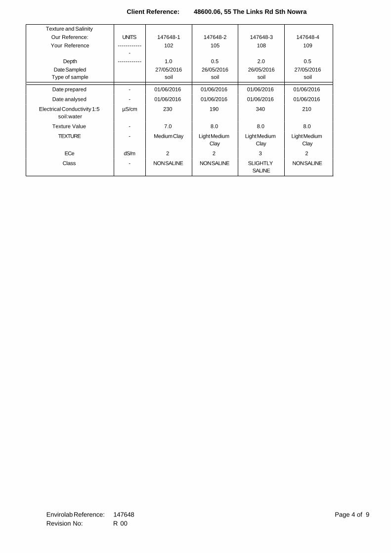
Client Reference: 48600.06, 55 The Links Rd Sth Nowra
Texture and Salinity
Our Reference: UNITS 147648-1 147648-2 147648-3 147648-4
Your Reference ------------
-
102 105 108 109
Depth ------------ 1.0 0.5 2.0 0.5
Date Sampled
Type of sample
27/05/2016
soil
26/05/2016
soil
26/05/2016
soil
27/05/2016
soil
Date prepared - 01/06/2016 01/06/2016 01/06/2016 01/06/2016
Date analysed - 01/06/2016 01/06/2016 01/06/2016 01/06/2016
Electrical Conductivity 1:5
soil:water
µS/cm 230 190 340 210
Texture Value - 7.0 8.0 8.0 8.0
TEXTURE - Medium Clay Light Medium
Clay
Light Medium
Clay
Light Medium
Clay
ECe dS/m 2 2 3 2
Class - NON SALINE NON SALINE SLIGHTLY
SALINE
NON SALINE
Page 4 of 9Envirolab Reference: 147648
Revision No: R 00

Client Reference: 48600.06, 55 The Links Rd Sth Nowra
Moisture
Our Reference: UNITS 147648-1 147648-2 147648-3 147648-4
Your Reference ------------
-
102 105 108 109
Depth ------------ 1.0 0.5 2.0 0.5
Date Sampled
Type of sample
27/05/2016
soil
26/05/2016
soil
26/05/2016
soil
27/05/2016
soil
Date prepared - 2/06/2016 2/06/2016 2/06/2016 2/06/2016
Date analysed - 2/06/2016 2/06/2016 2/06/2016 2/06/2016
Moisture % 24 9.1 13 12
Page 5 of 9Envirolab Reference: 147648
Revision No: R 00

Client Reference: 48600.06, 55 The Links Rd Sth Nowra
Method ID Methodology Summary
Metals-009 Determination of exchangeable cations and cation exchange capacity in soils using 1M Ammonium Chloride
exchange and ICP-AES analytical finish.
Inorg-001 pH - Measured using pH meter and electrode in accordance with APHA latest edition, 4500-H+. Please note
that the results for water analyses are indicative only, as analysis outside of the APHA storage times.
Inorg-081 Anions - a range of Anions are determined by Ion Chromatography, in accordance with APHA latest edition,
4110-B. Alternatively determined by colourimetry/turbidity using Discrete Analyer.
Inorg-002 Conductivity and Salinity - measured using a conductivity cell at 25oC in accordance with APHA latest edition
2510 and Rayment & Lyons.
Inorg-008 Moisture content determined by heating at 105+/-5 deg C for a minimum of 12 hours.
Page 6 of 9Envirolab Reference: 147648
Revision No: R 00

Client Reference: 48600.06, 55 The Links Rd Sth Nowra
QUALITY CONTROL UNITS PQL METHOD Blank Duplicate
Sm#
Duplicate results Spike Sm# Spike %
Recovery
ESP/CEC Base ll Duplicate ll %RPD
Date prepared - 02/06/2
016
147648-1 02/06/2016 || 02/06/2016 LCS-1 02/06/2016
Date analysed - 02/06/2
016
147648-1 02/06/2016 || 02/06/2016 LCS-1 02/06/2016
Exchangeable Ca meq/100
g
0.1 Metals-009 <0.1 147648-1 0.2 || 0.1 || RPD: 67 LCS-1 115%
Exchangeable K meq/100
g
0.1 Metals-009 <0.1 147648-1 0.2 || 0.2 || RPD: 0 LCS-1 107%
Exchangeable Mg meq/100
g
0.1 Metals-009 <0.1 147648-1 4.4 || 4.7 || RPD: 7 LCS-1 111%
Exchangeable Na meq/100
g
0.1 Metals-009 <0.1 147648-1 1.9 || 1.9 || RPD: 0 LCS-1 114%
ESP % 1 Metals-009 <1 147648-1 28 || 27 || RPD: 4 [NR] [NR]
QUALITY CONTROL UNITS PQL METHOD Blank Duplicate
Sm#
Duplicate results Spike Sm# Spike %
Recovery
Misc Inorg - Soil Base ll Duplicate ll %RPD
Date prepared - 01/06/2
016
147648-1 01/06/2016 || 01/06/2016 LCS- 01/06/2016
Date analysed - 01/06/2
016
147648-1 01/06/2016 || 01/06/2016 LCS- 01/06/2016
pH 1:5 soil:water pH Units Inorg-001 [NT] 147648-1 5.1 || 5.1 || RPD: 0 LCS- 101%
Chloride, Cl 1:5
soil:water
mg/kg 10 Inorg-081 <10 147648-1 210 || 170 || RPD: 21 LCS- 102%
Sulphate, SO4 1:5
soil:water
mg/kg 10 Inorg-081 <10 147648-1 170 || 130 || RPD: 27 LCS- 113%
QUALITY CONTROL UNITS PQL METHOD Blank Duplicate
Sm#
Duplicate results Spike Sm# Spike %
Recovery
Texture and Salinity Base ll Duplicate ll %RPD
Date prepared - 01/06/2
016
147648-1 01/06/2016 || 01/06/2016 LCS-1 01/06/2016
Date analysed - 01/06/2
016
147648-1 01/06/2016 || 01/06/2016 LCS-1 01/06/2016
Electrical Conductivity
1:5 soil:water
µS/cm 1 Inorg-002 <1 147648-1 230 || 230 || RPD: 0 LCS-1 96%
Texture Value - Inorg-002 [NT] 147648-1 7.0 || 7.0 || RPD: 0 [NR] [NR]
Class - [NT] 147648-1 NON SALINE || NON
SALINE
[NR] [NR]
QUALITY CONTROL UNITS Dup. Sm# Duplicate Spike Sm# Spike % Recovery
Misc Inorg - Soil Base + Duplicate + %RPD
Date prepared - [NT] [NT] 147648-2 01/06/2016
Date analysed - [NT] [NT] 147648-2 01/06/2016
pH 1:5 soil:water pH Units [NT] [NT] [NR] [NR]
Chloride, Cl 1:5 soil:water mg/kg [NT] [NT] 147648-2 86%
Sulphate, SO4 1:5
soil:water
mg/kg [NT] [NT] 147648-2 105%
Page 7 of 9Envirolab Reference: 147648
Revision No: R 00

Client Reference: 48600.06, 55 The Links Rd Sth Nowra
Report Comments:
Asbestos ID was analysed by Approved Identifier: Not applicable for this job
Asbestos ID was authorised by Approved Signatory: Not applicable for this job
INS: Insufficient sample for this test PQL: Practical Quantitation Limit NT: Not tested
NR: Test not required RPD: Relative Percent Difference NA: Test not required
<: Less than >: Greater than LCS: Laboratory Control Sample
Page 8 of 9Envirolab Reference: 147648
Revision No: R 00

Client Reference: 48600.06, 55 The Links Rd Sth Nowra
Quality Control Definitions
Blank: This is the component of the analytical signal which is not derived from the sample but from reagents,
glassware etc, can be determined by processing solvents and reagents in exactly the same manner as for samples.
Duplicate : This is the complete duplicate analysis of a sample from the process batch. If possible, the sample
selected should be one where the analyte concentration is easily measurable.
Matrix Spike : A portion of the sample is spiked with a known concentration of target analyte. The purpose of the matrix
spike is to monitor the performance of the analytical method used and to determine whether matrix interferences exist.
LCS (Laboratory Control Sample) : This comprises either a standard reference material or a control matrix (such as a blank
sand or water) fortified with analytes representative of the analyte class. It is simply a check sample.
Surrogate Spike: Surrogates are known additions to each sample, blank, matrix spike and LCS in a batch, of compounds
which are similar to the analyte of interest, however are not expected to be found in real samples.
Laboratory Acceptance Criteria
Duplicate sample and matrix spike recoveries may not be reported on smaller jobs, however, were analysed at a frequency
to meet or exceed NEPM requirements. All samples are tested in batches of 20. The duplicate sample RPD and matrix
spike recoveries for the batch were within the laboratory acceptance criteria.
Filters, swabs, wipes, tubes and badges will not have duplicate data as the whole sample is generally extracted
during sample extraction.
Spikes for Physical and Aggregate Tests are not applicable.
For VOCs in water samples, three vials are required for duplicate or spike analysis.
Duplicates: <5xPQL - any RPD is acceptable; >5xPQL - 0-50% RPD is acceptable.
Matrix Spikes, LCS and Surrogate recoveries: Generally 70-130% for inorganics/metals; 60-140%
for organics (+/-50% surrogates) and 10-140% for labile SVOCs (including labile surrogates), ultra trace organics
and speciated phenols is acceptable.
In circumstances where no duplicate and/or sample spike has been reported at 1 in 10 and/or 1 in 20 samples
respectively, the sample volume submitted was insufficient in order to satisfy laboratory QA/QC protocols.
When samples are received where certain analytes are outside of recommended technical holding times (THTs),
the analysis has proceeded. Where analytes are on the verge of breaching THTs, every effort will be made to analyse
within the THT or as soon as practicable.
Where sampling dates are not provided, Envirolab are not in a position to comment on the validity
of the analysis where recommended technical holding times may have been breached.
Page 9 of 9Envirolab Reference: 147648
Revision No: R 00

CERTIFICATE OF ANALYSIS 147563
Client:
Douglas Partners Unanderra
Unit 1, 1 Luso Drive
Unanderra
NSW 2526
Attention: Arthur Castrissios
Sample log in details:
Your Reference: 48600.06, 55 The Links Rd Sth Nowra
No. of samples: 4 soils
Date samples received / completed instructions received 30/05/16 / 30/05/16
This report replaces the one dated 06/06/2016 (R00) due to amendment of sample type.
Analysis Details:
Please refer to the following pages for results, methodology summary and quality control data.
Samples were analysed as received from the client. Results relate specifically to the samples as received.
Results are reported on a dry weight basis for solids and on an as received basis for other matrices.
Please refer to the last page of this report for any comments relating to the results.
Report Details:
Date results requested by: / Issue Date: 6/06/16 / 15/06/16
Date of Preliminary Report: Not Issued
NATA accreditation number 2901. This document shall not be reproduced except in full.
Accredited for compliance with ISO/IEC 17025. Tests not covered by NATA are denoted with *.
Results Approved By:
Page 1 of 18Envirolab Reference: 147563
Revision No: R 01

Client Reference: 48600.06, 55 The Links Rd Sth Nowra
vTRH(C6-C10)/BTEXN in Soil
Our Reference: UNITS 147563-1 147563-2 147563-3 147563-4
Your Reference ------------
-
101 108 110 112
Depth ------------ 0.1 0.1 0.1 0.5
Date Sampled
Type of sample
26/05/2016
Soil
27/05/2016
Soil
27/05/2016
Soil
27/05/2016
Soil
Date extracted - 31/05/2016 31/05/2016 31/05/2016 31/05/2016
Date analysed - 01/06/2016 01/06/2016 01/06/2016 01/06/2016
TRH C6 - C9 mg/kg <25 <25 <25 <25
TRH C6 - C10 mg/kg <25 <25 <25 <25
vTPH C6 - C10 less BTEX
(F1)
mg/kg <25 <25 <25 <25
Benzene mg/kg <0.2 <0.2 <0.2 <0.2
Toluene mg/kg <0.5 <0.5 <0.5 <0.5
Ethylbenzene mg/kg <1 <1 <1 <1
m+p-xylene mg/kg <2 <2 <2 <2
o-Xylene mg/kg <1 <1 <1 <1
naphthalene mg/kg <1 <1 <1 <1
Surrogate aaa-Trifluorotoluene % 108 99 99 109
Page 2 of 18Envirolab Reference: 147563
Revision No: R 01
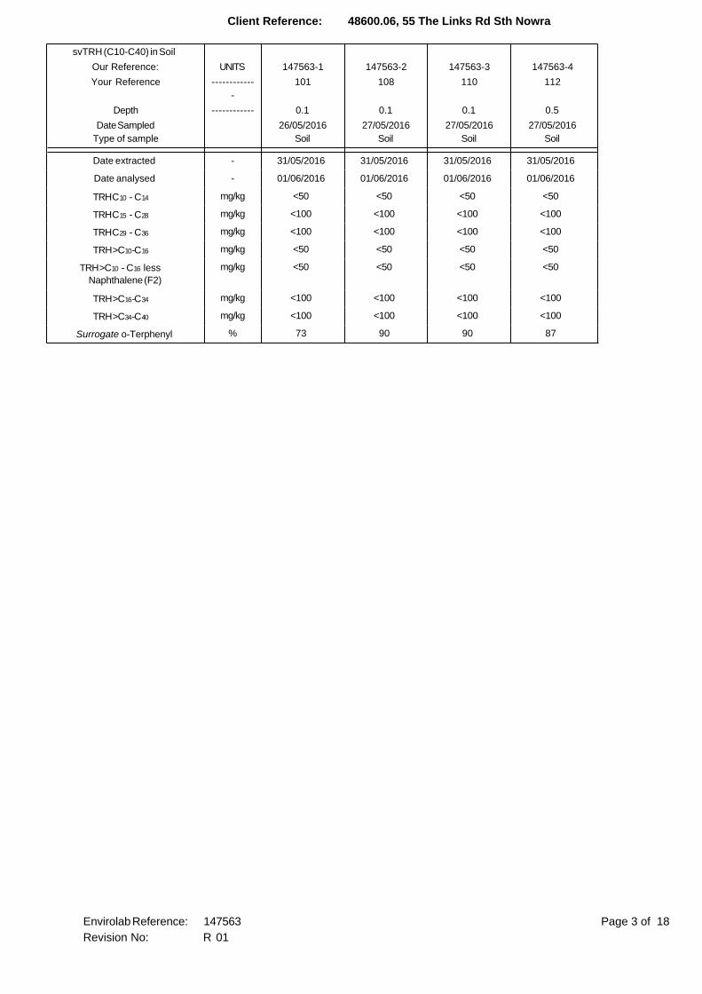
Client Reference: 48600.06, 55 The Links Rd Sth Nowra
svTRH (C10-C40) in Soil
Our Reference: UNITS 147563-1 147563-2 147563-3 147563-4
Your Reference ------------
-
101 108 110 112
Depth ------------ 0.1 0.1 0.1 0.5
Date Sampled
Type of sample
26/05/2016
Soil
27/05/2016
Soil
27/05/2016
Soil
27/05/2016
Soil
Date extracted - 31/05/2016 31/05/2016 31/05/2016 31/05/2016
Date analysed - 01/06/2016 01/06/2016 01/06/2016 01/06/2016
TRH C10 - C14 mg/kg <50 <50 <50 <50
TRH C15 - C28 mg/kg <100 <100 <100 <100
TRH C29 - C36 mg/kg <100 <100 <100 <100
TRH >C10-C16 mg/kg <50 <50 <50 <50
TRH >C10 - C16 less
Naphthalene (F2)
mg/kg <50 <50 <50 <50
TRH >C16-C34 mg/kg <100 <100 <100 <100
TRH >C34-C40 mg/kg <100 <100 <100 <100
Surrogate o-Terphenyl % 73 90 90 87
Page 3 of 18Envirolab Reference: 147563
Revision No: R 01

Client Reference: 48600.06, 55 The Links Rd Sth Nowra
PAHs in Soil
Our Reference: UNITS 147563-1 147563-2 147563-3 147563-4
Your Reference ------------
-
101 108 110 112
Depth ------------ 0.1 0.1 0.1 0.5
Date Sampled
Type of sample
26/05/2016
Soil
27/05/2016
Soil
27/05/2016
Soil
27/05/2016
Soil
Date extracted - 31/05/2016 31/05/2016 31/05/2016 31/05/2016
Date analysed - 31/05/2016 31/05/2016 31/05/2016 31/05/2016
Naphthalene mg/kg <0.1 <0.1 <0.1 <0.1
Acenaphthylene mg/kg <0.1 <0.1 <0.1 <0.1
Acenaphthene mg/kg <0.1 <0.1 <0.1 <0.1
Fluorene mg/kg <0.1 <0.1 <0.1 <0.1
Phenanthrene mg/kg <0.1 <0.1 <0.1 <0.1
Anthracene mg/kg <0.1 <0.1 <0.1 <0.1
Fluoranthene mg/kg <0.1 <0.1 <0.1 <0.1
Pyrene mg/kg <0.1 <0.1 <0.1 <0.1
Benzo(a)anthracene mg/kg <0.1 <0.1 <0.1 <0.1
Chrysene mg/kg <0.1 <0.1 <0.1 <0.1
Benzo(b,j+k)fluoranthene mg/kg <0.2 <0.2 <0.2 <0.2
Benzo(a)pyrene mg/kg <0.05 <0.05 <0.05 <0.05
Indeno(1,2,3-c,d)pyrene mg/kg <0.1 <0.1 <0.1 <0.1
Dibenzo(a,h)anthracene mg/kg <0.1 <0.1 <0.1 <0.1
Benzo(g,h,i)perylene mg/kg <0.1 <0.1 <0.1 <0.1
Benzo(a)pyrene TEQ calc (zero) mg/kg <0.5 <0.5 <0.5 <0.5
Benzo(a)pyrene TEQ calc(half) mg/kg <0.5 <0.5 <0.5 <0.5
Benzo(a)pyrene TEQ calc(PQL) mg/kg <0.5 <0.5 <0.5 <0.5
Total Positive PAHs mg/kg NIL (+)VE NIL (+)VE NIL (+)VE NIL (+)VE
Surrogate p-Terphenyl-d14 % 96 89 93 82
Page 4 of 18Envirolab Reference: 147563
Revision No: R 01

Client Reference: 48600.06, 55 The Links Rd Sth Nowra
Organochlorine Pesticides in soil
Our Reference: UNITS 147563-1 147563-2 147563-3 147563-4
Your Reference ------------
-
101 108 110 112
Depth ------------ 0.1 0.1 0.1 0.5
Date Sampled
Type of sample
26/05/2016
Soil
27/05/2016
Soil
27/05/2016
Soil
27/05/2016
Soil
Date extracted - 31/05/2030 31/05/2031 31/05/2032 31/05/2033
Date analysed - 31/05/2016 31/05/2016 31/05/2016 31/05/2016
HCB mg/kg <0.1 <0.1 <0.1 <0.1
alpha-BHC mg/kg <0.1 <0.1 <0.1 <0.1
gamma-BHC mg/kg <0.1 <0.1 <0.1 <0.1
beta-BHC mg/kg <0.1 <0.1 <0.1 <0.1
Heptachlor mg/kg <0.1 <0.1 <0.1 <0.1
delta-BHC mg/kg <0.1 <0.1 <0.1 <0.1
Aldrin mg/kg <0.1 <0.1 <0.1 <0.1
Heptachlor Epoxide mg/kg <0.1 <0.1 <0.1 <0.1
gamma-Chlordane mg/kg <0.1 <0.1 <0.1 <0.1
alpha-chlordane mg/kg <0.1 <0.1 <0.1 <0.1
Endosulfan I mg/kg <0.1 <0.1 <0.1 <0.1
pp-DDE mg/kg <0.1 <0.1 <0.1 <0.1
Dieldrin mg/kg <0.1 <0.1 <0.1 <0.1
Endrin mg/kg <0.1 <0.1 <0.1 <0.1
pp-DDD mg/kg <0.1 <0.1 <0.1 <0.1
Endosulfan II mg/kg <0.1 <0.1 <0.1 <0.1
pp-DDT mg/kg <0.1 <0.1 <0.1 <0.1
Endrin Aldehyde mg/kg <0.1 <0.1 <0.1 <0.1
Endosulfan Sulphate mg/kg <0.1 <0.1 <0.1 <0.1
Methoxychlor mg/kg <0.1 <0.1 <0.1 <0.1
Surrogate TCMX % 90 87 89 86
Page 5 of 18Envirolab Reference: 147563
Revision No: R 01

Client Reference: 48600.06, 55 The Links Rd Sth Nowra
Organophosphorus Pesticides
Our Reference: UNITS 147563-1 147563-2 147563-3 147563-4
Your Reference ------------
-
101 108 110 112
Depth ------------ 0.1 0.1 0.1 0.5
Date Sampled
Type of sample
26/05/2016
Soil
27/05/2016
Soil
27/05/2016
Soil
27/05/2016
Soil
Date extracted - 31/05/2030 31/05/2031 31/05/2032 31/05/2033
Date analysed - 31/05/2016 31/05/2016 31/05/2016 31/05/2016
Azinphos-methyl (Guthion) mg/kg <0.1 <0.1 <0.1 <0.1
Bromophos-ethyl mg/kg <0.1 <0.1 <0.1 <0.1
Chlorpyriphos mg/kg <0.1 <0.1 <0.1 <0.1
Chlorpyriphos-methyl mg/kg <0.1 <0.1 <0.1 <0.1
Diazinon mg/kg <0.1 <0.1 <0.1 <0.1
Dichlorvos mg/kg <0.1 <0.1 <0.1 <0.1
Dimethoate mg/kg <0.1 <0.1 <0.1 <0.1
Ethion mg/kg <0.1 <0.1 <0.1 <0.1
Fenitrothion mg/kg <0.1 <0.1 <0.1 <0.1
Malathion mg/kg <0.1 <0.1 <0.1 <0.1
Parathion mg/kg <0.1 <0.1 <0.1 <0.1
Ronnel mg/kg <0.1 <0.1 <0.1 <0.1
Surrogate TCMX % 90 87 89 86
Page 6 of 18Envirolab Reference: 147563
Revision No: R 01

Client Reference: 48600.06, 55 The Links Rd Sth Nowra
PCBs in Soil
Our Reference: UNITS 147563-1 147563-2 147563-3 147563-4
Your Reference ------------
-
101 108 110 112
Depth ------------ 0.1 0.1 0.1 0.5
Date Sampled
Type of sample
26/05/2016
Soil
27/05/2016
Soil
27/05/2016
Soil
27/05/2016
Soil
Date extracted - 31/05/2030 31/05/2031 31/05/2032 31/05/2033
Date analysed - 31/05/2016 31/05/2016 31/05/2016 31/05/2016
Aroclor 1016 mg/kg <0.1 <0.1 <0.1 <0.1
Aroclor 1221 mg/kg <0.1 <0.1 <0.1 <0.1
Aroclor 1232 mg/kg <0.1 <0.1 <0.1 <0.1
Aroclor 1242 mg/kg <0.1 <0.1 <0.1 <0.1
Aroclor 1248 mg/kg <0.1 <0.1 <0.1 <0.1
Aroclor 1254 mg/kg <0.1 <0.1 <0.1 <0.1
Aroclor 1260 mg/kg <0.1 <0.1 <0.1 <0.1
Surrogate TCLMX % 90 87 89 86
Page 7 of 18Envirolab Reference: 147563
Revision No: R 01

Client Reference: 48600.06, 55 The Links Rd Sth Nowra
Acid Extractable metals in soil
Our Reference: UNITS 147563-1 147563-2 147563-3 147563-4
Your Reference ------------
-
101 108 110 112
Depth ------------ 0.1 0.1 0.1 0.5
Date Sampled
Type of sample
26/05/2016
Soil
27/05/2016
Soil
27/05/2016
Soil
27/05/2016
Soil
Date prepared - 30/05/2016 30/05/2016 30/05/2016 30/05/2016
Date analysed - 31/05/2016 31/05/2016 31/05/2016 31/05/2016
Arsenic mg/kg 6 6 7 8
Cadmium mg/kg <0.4 <0.4 <0.4 <0.4
Chromium mg/kg 12 12 14 16
Copper mg/kg 20 16 17 25
Lead mg/kg 8 10 7 10
Mercury mg/kg <0.1 <0.1 <0.1 <0.1
Nickel mg/kg 5 4 2 6
Zinc mg/kg 21 18 10 34
Page 8 of 18Envirolab Reference: 147563
Revision No: R 01

Client Reference: 48600.06, 55 The Links Rd Sth Nowra
Misc Soil - Inorg
Our Reference: UNITS 147563-1 147563-2 147563-3 147563-4
Your Reference ------------
-
101 108 110 112
Depth ------------ 0.1 0.1 0.1 0.5
Date Sampled
Type of sample
26/05/2016
Soil
27/05/2016
Soil
27/05/2016
Soil
27/05/2016
Soil
Date prepared - 30/05/2016 30/05/2016 30/05/2016 30/05/2016
Date analysed - 31/05/2016 31/05/2016 31/05/2016 31/05/2016
Total Phenolics (as Phenol) mg/kg <5 <5 <5 <5
Page 9 of 18Envirolab Reference: 147563
Revision No: R 01

Client Reference: 48600.06, 55 The Links Rd Sth Nowra
Moisture
Our Reference: UNITS 147563-1 147563-2 147563-3 147563-4
Your Reference ------------
-
101 108 110 112
Depth ------------ 0.1 0.1 0.1 0.5
Date Sampled
Type of sample
26/05/2016
Soil
27/05/2016
Soil
27/05/2016
Soil
27/05/2016
Soil
Date prepared - 30/05/2016 30/05/2016 30/05/2016 30/05/2016
Date analysed - 31/05/2016 31/05/2016 31/05/2016 31/05/2016
Moisture % 11 8.9 19 20
Page 10 of 18Envirolab Reference: 147563
Revision No: R 01

Client Reference: 48600.06, 55 The Links Rd Sth Nowra
Asbestos ID - soils
Our Reference: UNITS 147563-1 147563-2 147563-3 147563-4
Your Reference ------------
-
101 108 110 112
Depth ------------ 0.1 0.1 0.1 0.5
Date Sampled
Type of sample
26/05/2016
Soil
27/05/2016
Soil
27/05/2016
Soil
27/05/2016
Soil
Date analysed - 3/06/2016 3/06/2016 3/06/2016 3/06/2016
Sample mass tested g Approx 25g Approx 15g Approx 15g Approx 25g
Sample Description - Brown coarse-
grained soil &
rocks
Brown coarse-
grained soil &
rocks
Brown coarse-
grained soil &
rocks
Brown coarse-
grained soil &
rocks
Asbestos ID in soil - No asbestos
detected at
reporting limit of
0.1g/kg
Organic fibres
detected
No asbestos
detected at
reporting limit of
0.1g/kg
Organic fibres
detected
No asbestos
detected at
reporting limit of
0.1g/kg
Organic fibres
detected
No asbestos
detected at
reporting limit of
0.1g/kg
Organic fibres
detected
Trace Analysis - No asbestos
detected
No asbestos
detected
No asbestos
detected
No asbestos
detected
Page 11 of 18Envirolab Reference: 147563
Revision No: R 01

Client Reference: 48600.06, 55 The Links Rd Sth Nowra
Method ID Methodology Summary
Org-016 Soil samples are extracted with methanol and spiked into water prior to analysing by purge and trap GC-MS.
Water samples are analysed directly by purge and trap GC-MS. F1 = (C6-C10)-BTEX as per NEPM B1
Guideline on Investigation Levels for Soil and Groundwater.
Org-014 Soil samples are extracted with methanol and spiked into water prior to analysing by purge and trap GC-MS.
Org-003 Soil samples are extracted with Dichloromethane/Acetone and waters with Dichloromethane and analysed by
GC-FID.
F2 = (>C10-C16)-Naphthalene as per NEPM B1 Guideline on Investigation Levels for Soil and Groundwater
(HSLs Tables 1A (3, 4)). Note Naphthalene is determined from the VOC analysis.
Org-012 Soil samples are extracted with Dichloromethane/Acetone and waters with Dichloromethane and analysed by
GC-MS. Benzo(a)pyrene TEQ as per NEPM B1 Guideline on Investigation Levels for Soil and Groundwater -
2013.
For soil results:-
1. ‘TEQ PQL’ values are assuming all contributing PAHs reported as <PQL are actually at the PQL. This is the
most conservative approach and can give false positive TEQs given that PAHs that contribute to the TEQ
calculation may not be present.
2. ‘TEQ zero’ values are assuming all contributing PAHs reported as <PQL are zero. This is the least
conservative approach and is more susceptible to false negative TEQs when PAHs that contribute to the TEQ
calculation are present but below PQL.
3. ‘TEQ half PQL’ values are assuming all contributing PAHs reported as <PQL are half the stipulated PQL.
Hence a mid-point between the most and least conservative approaches above.
Note, the Total +ve PAHs PQL is reflective of the lowest individual PQL and is therefore" Total +ve PAHs" is
simply a sum of the positive individual PAHs.
Org-005 Soil samples are extracted with dichloromethane/acetone and waters with dichloromethane and analysed by
GC with dual ECD's.
Org-008 Soil samples are extracted with dichloromethane/acetone and waters with dichloromethane and analysed by
GC with dual ECD's.
Org-006 Soil samples are extracted with dichloromethane/acetone and waters with dichloromethane and analysed by
GC-ECD.
Metals-020 Determination of various metals by ICP-AES.
Metals-021 Determination of Mercury by Cold Vapour AAS.
Inorg-031 Total Phenolics by segmented flow analyser (in line distillation with colourimetric finish).
Solids are extracted in a caustic media prior to analysis.
Inorg-008 Moisture content determined by heating at 105+/-5 deg C for a minimum of 12 hours.
ASB-001 Asbestos ID - Qualitative identification of asbestos in bulk samples using Polarised Light Microscopy and
Dispersion Staining Techniques including Synthetic Mineral Fibre and Organic Fibre as per Australian Standard
4964-2004.
Page 12 of 18Envirolab Reference: 147563
Revision No: R 01

Client Reference: 48600.06, 55 The Links Rd Sth Nowra
QUALITY CONTROL UNITS PQL METHOD Blank Duplicate
Sm#
Duplicate results Spike Sm# Spike %
Recovery
vTRH(C6-C10)/BTEXN in
Soil
Base ll Duplicate ll %RPD
Date extracted - 31/05/2
016
[NT] [NT] LCS-2 31/05/2016
Date analysed - 01/06/2
016
[NT] [NT] LCS-2 01/06/2016
TRH C6 - C9 mg/kg 25 Org-016 <25 [NT] [NT] LCS-2 72%
TRH C6 - C10 mg/kg 25 Org-016 <25 [NT] [NT] LCS-2 72%
Benzene mg/kg 0.2 Org-016 <0.2 [NT] [NT] LCS-2 72%
Toluene mg/kg 0.5 Org-016 <0.5 [NT] [NT] LCS-2 74%
Ethylbenzene mg/kg 1 Org-016 <1 [NT] [NT] LCS-2 70%
m+p-xylene mg/kg 2 Org-016 <2 [NT] [NT] LCS-2 73%
o-Xylene mg/kg 1 Org-016 <1 [NT] [NT] LCS-2 71%
naphthalene mg/kg 1 Org-014 <1 [NT] [NT] [NR] [NR]
Surrogate aaa-
Trifluorotoluene
% Org-016 111 [NT] [NT] LCS-2 102%
QUALITY CONTROL UNITS PQL METHOD Blank Duplicate
Sm#
Duplicate results Spike Sm# Spike %
Recovery
svTRH (C10-C40) in Soil Base ll Duplicate ll %RPD
Date extracted - 31/05/2
016
[NT] [NT] LCS-2 31/05/2016
Date analysed - 01/06/2
016
[NT] [NT] LCS-2 01/06/2016
TRH C10 - C14 mg/kg 50 Org-003 <50 [NT] [NT] LCS-2 108%
TRH C15 - C28 mg/kg 100 Org-003 <100 [NT] [NT] LCS-2 89%
TRH C29 - C36 mg/kg 100 Org-003 <100 [NT] [NT] LCS-2 108%
TRH >C10-C16 mg/kg 50 Org-003 <50 [NT] [NT] LCS-2 108%
TRH >C16-C34 mg/kg 100 Org-003 <100 [NT] [NT] LCS-2 89%
TRH >C34-C40 mg/kg 100 Org-003 <100 [NT] [NT] LCS-2 108%
Surrogate o-Terphenyl % Org-003 76 [NT] [NT] LCS-2 83%
QUALITY CONTROL UNITS PQL METHOD Blank Duplicate
Sm#
Duplicate results Spike Sm# Spike %
Recovery
PAHs in Soil Base ll Duplicate ll %RPD
Date extracted - 31/05/2
016
[NT] [NT] LCS-2 31/05/2016
Date analysed - 31/05/2
016
[NT] [NT] LCS-2 31/05/2016
Naphthalene mg/kg 0.1 Org-012 <0.1 [NT] [NT] LCS-2 107%
Acenaphthylene mg/kg 0.1 Org-012 <0.1 [NT] [NT] [NR] [NR]
Acenaphthene mg/kg 0.1 Org-012 <0.1 [NT] [NT] [NR] [NR]
Fluorene mg/kg 0.1 Org-012 <0.1 [NT] [NT] LCS-2 103%
Phenanthrene mg/kg 0.1 Org-012 <0.1 [NT] [NT] LCS-2 112%
Anthracene mg/kg 0.1 Org-012 <0.1 [NT] [NT] [NR] [NR]
Fluoranthene mg/kg 0.1 Org-012 <0.1 [NT] [NT] LCS-2 109%
Pyrene mg/kg 0.1 Org-012 <0.1 [NT] [NT] LCS-2 102%
Benzo(a)anthracene mg/kg 0.1 Org-012 <0.1 [NT] [NT] [NR] [NR]
Chrysene mg/kg 0.1 Org-012 <0.1 [NT] [NT] LCS-2 88%
Benzo(b,j+k)
fluoranthene
mg/kg 0.2 Org-012 <0.2 [NT] [NT] [NR] [NR]
Page 13 of 18Envirolab Reference: 147563
Revision No: R 01

Client Reference: 48600.06, 55 The Links Rd Sth Nowra
QUALITY CONTROL UNITS PQL METHOD Blank Duplicate
Sm#
Duplicate results Spike Sm# Spike %
Recovery
PAHs in Soil Base ll Duplicate ll %RPD
Benzo(a)pyrene mg/kg 0.05 Org-012 <0.05 [NT] [NT] LCS-2 108%
Indeno(1,2,3-c,d)pyrene mg/kg 0.1 Org-012 <0.1 [NT] [NT] [NR] [NR]
Dibenzo(a,h)anthracene mg/kg 0.1 Org-012 <0.1 [NT] [NT] [NR] [NR]
Benzo(g,h,i)perylene mg/kg 0.1 Org-012 <0.1 [NT] [NT] [NR] [NR]
Surrogate p-Terphenyl-
d14
% Org-012 98 [NT] [NT] LCS-2 116%
QUALITY CONTROL UNITS PQL METHOD Blank Duplicate
Sm#
Duplicate results Spike Sm# Spike %
Recovery
Organochlorine
Pesticides in soil
Base ll Duplicate ll %RPD
Date extracted - 31/05/2
030
[NT] [NT] LCS-2 31/05/2030
Date analysed - 31/05/2
016
[NT] [NT] LCS-2 31/05/2016
HCB mg/kg 0.1 Org-005 <0.1 [NT] [NT] [NR] [NR]
alpha-BHC mg/kg 0.1 Org-005 <0.1 [NT] [NT] LCS-2 98%
gamma-BHC mg/kg 0.1 Org-005 <0.1 [NT] [NT] [NR] [NR]
beta-BHC mg/kg 0.1 Org-005 <0.1 [NT] [NT] LCS-2 118%
Heptachlor mg/kg 0.1 Org-005 <0.1 [NT] [NT] LCS-2 92%
delta-BHC mg/kg 0.1 Org-005 <0.1 [NT] [NT] [NR] [NR]
Aldrin mg/kg 0.1 Org-005 <0.1 [NT] [NT] LCS-2 94%
Heptachlor Epoxide mg/kg 0.1 Org-005 <0.1 [NT] [NT] LCS-2 89%
gamma-Chlordane mg/kg 0.1 Org-005 <0.1 [NT] [NT] [NR] [NR]
alpha-chlordane mg/kg 0.1 Org-005 <0.1 [NT] [NT] [NR] [NR]
Endosulfan I mg/kg 0.1 Org-005 <0.1 [NT] [NT] [NR] [NR]
pp-DDE mg/kg 0.1 Org-005 <0.1 [NT] [NT] LCS-2 80%
Dieldrin mg/kg 0.1 Org-005 <0.1 [NT] [NT] LCS-2 96%
Endrin mg/kg 0.1 Org-005 <0.1 [NT] [NT] LCS-2 97%
pp-DDD mg/kg 0.1 Org-005 <0.1 [NT] [NT] LCS-2 100%
Endosulfan II mg/kg 0.1 Org-005 <0.1 [NT] [NT] [NR] [NR]
pp-DDT mg/kg 0.1 Org-005 <0.1 [NT] [NT] [NR] [NR]
Endrin Aldehyde mg/kg 0.1 Org-005 <0.1 [NT] [NT] [NR] [NR]
Endosulfan Sulphate mg/kg 0.1 Org-005 <0.1 [NT] [NT] LCS-2 88%
Methoxychlor mg/kg 0.1 Org-005 <0.1 [NT] [NT] [NR] [NR]
Surrogate TCMX % Org-005 90 [NT] [NT] LCS-2 89%
Page 14 of 18Envirolab Reference: 147563
Revision No: R 01

Client Reference: 48600.06, 55 The Links Rd Sth Nowra
QUALITY CONTROL UNITS PQL METHOD Blank Duplicate
Sm#
Duplicate results Spike Sm# Spike %
Recovery
Organophosphorus
Pesticides
Base ll Duplicate ll %RPD
Date extracted - 31/05/2
030
[NT] [NT] LCS-2 31/05/2030
Date analysed - 31/05/2
016
[NT] [NT] LCS-2 31/05/2016
Azinphos-methyl
(Guthion)
mg/kg 0.1 Org-008 <0.1 [NT] [NT] [NR] [NR]
Bromophos-ethyl mg/kg 0.1 Org-008 <0.1 [NT] [NT] [NR] [NR]
Chlorpyriphos mg/kg 0.1 Org-008 <0.1 [NT] [NT] LCS-2 88%
Chlorpyriphos-methyl mg/kg 0.1 Org-008 <0.1 [NT] [NT] [NR] [NR]
Diazinon mg/kg 0.1 Org-008 <0.1 [NT] [NT] [NR] [NR]
Dichlorvos mg/kg 0.1 Org-008 <0.1 [NT] [NT] LCS-2 86%
Dimethoate mg/kg 0.1 Org-008 <0.1 [NT] [NT] [NR] [NR]
Ethion mg/kg 0.1 Org-008 <0.1 [NT] [NT] LCS-2 93%
Fenitrothion mg/kg 0.1 Org-008 <0.1 [NT] [NT] LCS-2 97%
Malathion mg/kg 0.1 Org-008 <0.1 [NT] [NT] LCS-2 77%
Parathion mg/kg 0.1 Org-008 <0.1 [NT] [NT] LCS-2 100%
Ronnel mg/kg 0.1 Org-008 <0.1 [NT] [NT] LCS-2 113%
Surrogate TCMX % Org-008 90 [NT] [NT] LCS-2 87%
QUALITY CONTROL UNITS PQL METHOD Blank Duplicate
Sm#
Duplicate results Spike Sm# Spike %
Recovery
PCBs in Soil Base ll Duplicate ll %RPD
Date extracted - 31/05/2
030
[NT] [NT] LCS-2 31/05/2030
Date analysed - 31/05/2
016
[NT] [NT] LCS-2 31/05/2016
Aroclor 1016 mg/kg 0.1 Org-006 <0.1 [NT] [NT] [NR] [NR]
Aroclor 1221 mg/kg 0.1 Org-006 <0.1 [NT] [NT] [NR] [NR]
Aroclor 1232 mg/kg 0.1 Org-006 <0.1 [NT] [NT] [NR] [NR]
Aroclor 1242 mg/kg 0.1 Org-006 <0.1 [NT] [NT] [NR] [NR]
Aroclor 1248 mg/kg 0.1 Org-006 <0.1 [NT] [NT] [NR] [NR]
Aroclor 1254 mg/kg 0.1 Org-006 <0.1 [NT] [NT] LCS-2 116%
Aroclor 1260 mg/kg 0.1 Org-006 <0.1 [NT] [NT] [NR] [NR]
Surrogate TCLMX % Org-006 90 [NT] [NT] LCS-2 87%
Page 15 of 18Envirolab Reference: 147563
Revision No: R 01

Client Reference: 48600.06, 55 The Links Rd Sth Nowra
QUALITY CONTROL UNITS PQL METHOD Blank Duplicate
Sm#
Duplicate results Spike Sm# Spike %
Recovery
Acid Extractable metals
in soil
Base ll Duplicate ll %RPD
Date prepared - 30/05/2
016
[NT] [NT] LCS-2 30/05/2016
Date analysed - 31/05/2
016
[NT] [NT] LCS-2 31/05/2016
Arsenic mg/kg 4 Metals-020 <4 [NT] [NT] LCS-2 102%
Cadmium mg/kg 0.4 Metals-020 <0.4 [NT] [NT] LCS-2 99%
Chromium mg/kg 1 Metals-020 <1 [NT] [NT] LCS-2 102%
Copper mg/kg 1 Metals-020 <1 [NT] [NT] LCS-2 101%
Lead mg/kg 1 Metals-020 <1 [NT] [NT] LCS-2 100%
Mercury mg/kg 0.1 Metals-021 <0.1 [NT] [NT] LCS-2 104%
Nickel mg/kg 1 Metals-020 <1 [NT] [NT] LCS-2 96%
Zinc mg/kg 1 Metals-020 <1 [NT] [NT] LCS-2 98%
QUALITY CONTROL UNITS PQL METHOD Blank Duplicate
Sm#
Duplicate results Spike Sm# Spike %
Recovery
Misc Soil - Inorg Base ll Duplicate ll %RPD
Date prepared - 31/05/2
016
[NT] [NT] LCS-1 31/05/2016
Date analysed - 31/05/2
016
[NT] [NT] LCS-1 31/05/2016
Total Phenolics (as
Phenol)
mg/kg 5 Inorg-031 <5 [NT] [NT] LCS-1 101%
Page 16 of 18Envirolab Reference: 147563
Revision No: R 01

Client Reference: 48600.06, 55 The Links Rd Sth Nowra
Report Comments:
Asbestos ID was analysed by Approved Identifier: Paul Ching
Asbestos ID was authorised by Approved Signatory: Paul Ching
INS: Insufficient sample for this test PQL: Practical Quantitation Limit NT: Not tested
NR: Test not required RPD: Relative Percent Difference NA: Test not required
<: Less than >: Greater than LCS: Laboratory Control Sample
Page 17 of 18Envirolab Reference: 147563
Revision No: R 01

Client Reference: 48600.06, 55 The Links Rd Sth Nowra
Quality Control Definitions
Blank: This is the component of the analytical signal which is not derived from the sample but from reagents,
glassware etc, can be determined by processing solvents and reagents in exactly the same manner as for samples.
Duplicate : This is the complete duplicate analysis of a sample from the process batch. If possible, the sample
selected should be one where the analyte concentration is easily measurable.
Matrix Spike : A portion of the sample is spiked with a known concentration of target analyte. The purpose of the matrix
spike is to monitor the performance of the analytical method used and to determine whether matrix interferences exist.
LCS (Laboratory Control Sample) : This comprises either a standard reference material or a control matrix (such as a blank
sand or water) fortified with analytes representative of the analyte class. It is simply a check sample.
Surrogate Spike: Surrogates are known additions to each sample, blank, matrix spike and LCS in a batch, of compounds
which are similar to the analyte of interest, however are not expected to be found in real samples.
Laboratory Acceptance Criteria
Duplicate sample and matrix spike recoveries may not be reported on smaller jobs, however, were analysed at a frequency
to meet or exceed NEPM requirements. All samples are tested in batches of 20. The duplicate sample RPD and matrix
spike recoveries for the batch were within the laboratory acceptance criteria.
Filters, swabs, wipes, tubes and badges will not have duplicate data as the whole sample is generally extracted
during sample extraction.
Spikes for Physical and Aggregate Tests are not applicable.
For VOCs in water samples, three vials are required for duplicate or spike analysis.
Duplicates: <5xPQL - any RPD is acceptable; >5xPQL - 0-50% RPD is acceptable.
Matrix Spikes, LCS and Surrogate recoveries: Generally 70-130% for inorganics/metals; 60-140%
for organics (+/-50% surrogates) and 10-140% for labile SVOCs (including labile surrogates), ultra trace organics
and speciated phenols is acceptable.
In circumstances where no duplicate and/or sample spike has been reported at 1 in 10 and/or 1 in 20 samples
respectively, the sample volume submitted was insufficient in order to satisfy laboratory QA/QC protocols.
When samples are received where certain analytes are outside of recommended technical holding times (THTs),
the analysis has proceeded. Where analytes are on the verge of breaching THTs, every effort will be made to analyse
within the THT or as soon as practicable.
Where sampling dates are not provided, Envirolab are not in a position to comment on the validity
of the analysis where recommended technical holding times may have been breached.
Page 18 of 18Envirolab Reference: 147563
Revision No: R 01

SAMPLE RECEIPT ADVICE
Client Details
Client Douglas Partners Unanderra Attention Arthur Castrissios
Sample Login Details
Your Reference 48600.06, 55 The Links Rd Sth Nowra
Envirolab Reference 147563 Date Sample Received 30/05/2016 Date Instructions Received 30/05/2016 Date Results Expected to be Reported 06/06/2016
Sample Condition
Samples received in appropriate condition for analysis YES
No. of Samples Provided 4 soils Turnaround Time Requested Standard Temperature on receipt (°C) 6.8 Cooling Method Ice Sampling Date Provided YES
Comments
Samples will be held for 1 month for water samples and 2 months for soil samples from date of receipt of samples
Please direct any queries to:
Aileen Hie Jacinta Hurst
Phone: 02 9910 6200 Phone: 02 9910 6200
Fax: 02 9910 6201 Fax: 02 9910 6201
Email: [email protected] Email: [email protected]
Sample and Testing Details on following page

Sample Id
vTR
H(C
6-
C1
0)/
BTE
XN
in S
oil
svTR
H (
C1
0-C
40
) in
Soil
PA
Hs
in S
oil
Org
an
och
lori
ne
Pes
tici
des
in s
oil
Org
an
op
ho
sph
oru
s
Pes
tici
des
PC
Bs
in S
oil
Aci
d E
xtra
cta
ble
met
als
in s
oil
Tota
l Ph
eno
lics
(as
Ph
eno
l)
Asb
esto
s ID
- s
oils
101-0.1 ✓ ✓ ✓ ✓ ✓ ✓ ✓ ✓ ✓
108-0.1 ✓ ✓ ✓ ✓ ✓ ✓ ✓ ✓ ✓
110-0.1 ✓ ✓ ✓ ✓ ✓ ✓ ✓ ✓ ✓
112-0.5 ✓ ✓ ✓ ✓ ✓ ✓ ✓ ✓ ✓


Appendix E
Building a Saline Environment CSIRO Foundation Publication
Author
Sian McGhie, Department of Infrastructure, Planning and Natural Resources
Acknowledgments
Building Code Development and Reform Unit (Department of Infrastructure, Planning and Natural Resources), Cement and Concrete Association
Elizabeth Madden, NSW Agriculture
Melissa Ryan, Department of Infrastructure, Planning and Natural Resources

© Department of Infrastructure, Planning and Natural Resources 2003Department of Infrastructure, Planning and Natural Resources 2003
This booklet is copy under the Berne Convention All rights reserved No reproduction without permission
First published 2003 Department of Infrastructure, Planning and Natural Resources22-33 Bridge Street Sydney NSW 2000
Building in a Saline EnvironmentISBN: 0 7347 5375 6Designed and printed by ClickMedia, Penrith Photographs: various sources
American Concrete Institute, A Guide To The Use Of Waterproofing, Damp proofing, Protective and Decorative Barriers Systems For Concrete, American Concrete Institute, Detroit, Michigan.
Andrews-Phaedonos, F ( 1997) The Effects Of Aggressive Agents On The Expected Service Life Of Reinforced Concrete Structures, Concrete In Australia October - December 1997
AS 1547, Australian Standard 1547 - 2000 On Site Domestic Waste Water Management, Standards Australia.
AS 2159, Australian Standard 2159 - 1995 Piling - Design and installation. Standards Australia.
AS 2870, Australian Standard 2870 - 1996 Residential Slabs and Footings, Standards Australia.
AS 3600, Australian Standard 3600 - 2001 Concrete Structures, Standards Australia.
AS 3660.1, Australian Standard 3360.1 - 2000 Termite Management - New Building Work, Standards Australia.
AS 3700, Australian Standard 3700 - 2001 Masonry Structures, Standards Australia.
AS 3798, Australian Standard 3798 - 1996 Guidelines For Earthworks For Commercial and Residential Developments, Standards Australia.
AS 4419, Australian Standard 4419 - 1998 Soils For Landscaping and Garden Use, Standards Australia.
AS 4456.6, Australian Standard 4456.6 - 1997 Masonry Units and Segmental Pavers - Methods of Test -Determining Potential To Effloresce, Standards Australia.
AS 4456.10, Australian Standard 4456.10 - 1997 Masonry Units and Segmental Pavers - Method of Determining Resistance to Salt Attack, Standards Australia.
Building Code of Australia
Building Research Establishment, (1981) Digest 245 - Rising Damp In Walls: Diagnosis and Treatment, BRE, UK.
Department of Environment and Natural Resources (1995), Rising Damp and Salt Attack, State Heritage Branch and City Of Adelaide.
Department of Land and Water Conservation, Local Government Salinity Initiative booklets
* Site Investigations for Urban Salinity ( 2002)
* Broad Scale Resources for Urban Salinity Assessment ( 2002)
* Indicators of Urban Salinity (2002)
Department of Infrastructure, Planning and Natural Resources
* Roads and Salinity (2003)
Electricity Association of NSW, ( 1997), Corrosion In The Electricity Supply Industry, Electricity Association of NSW, ISBN 0 7313109 26
Guiguis,S. Technical Note 57, (1989) Durable Concrete Structures, Cement and Concrete Association Of Australia.
Guiguis,S. Technical Note 59, (1989) Hydaulic Cements - Properties and Characteristics, Cement and Concrete Association Of Australia.
Lume E. (1998?), Concrete In Saline Groundwater Environments, Cement and Concrete Association of Australia,
Massari G, Massari I, (1993), Damp Buildings Old and New, International Centre For The Study Of The Preservation And Restoration Of Cultural Property, Rome.
Patterson, R. (draft 2001) Septic Safe Technical Reference Sheet “ Consideration of Soil Salinity When Assessing Land Application of Effluent”, Department of Local Government.
South Australian Salt Damp Research Committee
* First Report of the Salt Damp Research Committee (1976)
* Second Report of the Salt Damp Research Committee Incorporating the Proceedings of the National Conference On Salt Damp.(1978)
* Third Report of the Salt Damp Research Committee (1981)
* How to Avoid Salt Damp (1978)
* Living With Salt Damp (1980)
References
17
Contents
Introduction 1
Sources of Water and Salt 2Infiltration Rates 3Porosity vs Permeability Porosity vs Permeability Porosity vs Permeability 3
The Reactions of Salts with Building MaterialsThe Reactions of Salts with Building Materials 5Concrete 5
Bricks Resistant to Salt and Water 7
Concrete Resistant to Salt and Water 8
Preventing Salt and Water Moving into the BuildingPreventing Salt and Water Moving into the Building 9
Maintaining Good Drainage on a Building SiteMaintaining Good Drainage on a Building Site 11
The Building Code of Australia 12
Australian Standards 13
References 17

Salts are a natural part of the Australian landscape. Concentrated salt and different types of salt, once dissolved and mobilised in water, can have an impact on the durability of some building material. This booklet looks at:
1. how salts get into building material
2. the effect salt and water can have on some building materials.
Through the explanation of the processes, ideas are given on how to build structures that are less susceptible to salt damage. Other booklets of the Local Government Salinity Initiative kit, ‘Broad Scale Resources For Urban Salinity Assessment’ and ‘Site Investigations For Urban Salinity’, can be used to determine if salty groundwater or salty soil are likely to be affecting a building. ‘Indicators Of Urban Salinity’, gives a guide to the range of symptoms salt and water damage can create in an urban environment. ‘Roads and Salinity’ looks at how to construct a road so that it resists the effects of salinity and does not adversely impact on salt and water processes.
Render showing signs that excess salt and water are present
Photo: NSW Agriculture
Bricks showing signs of salt and water damage
Photo: NSW Agriculture
Paintwork blistering due to the accumulation of salt
Photo: DIPNR
Sandstone showing signs of salt and water damage
Photo: NSW Agriculture
Introduction
Verandah post showing signs of salt and water damage
Salinity and the Electricity Industry
Concrete poles are being used increasingly within the electricity supply industry because of their low maintenance requirements, long life and cost effectiveness. These power poles are often constructed of concrete with internal steel reinforcing. Rust stains, cracking and spalling of the concrete have been observed in situations where the alkalinity of the concrete and the cover of the concrete over the steel reinforcing have not been adequate to protect the internal steel from corrosion. This corrosion is caused by saline soils, galvanic couples between the reinforcing steel and dissimilar metals, and stray direct electric current.
Since the late 1960s it has become common practice for steel structures in the electricity industry to have their foundations encased in concrete in order to limit corrosion. Concrete cover of at least 70mm is recommended.
Source: Electricity Association of NSW, (1997), Corrosion
In The Electricity Supply Industry
Electricity supply pole with salinity vegetation indicators
Photo:DIPNR
116
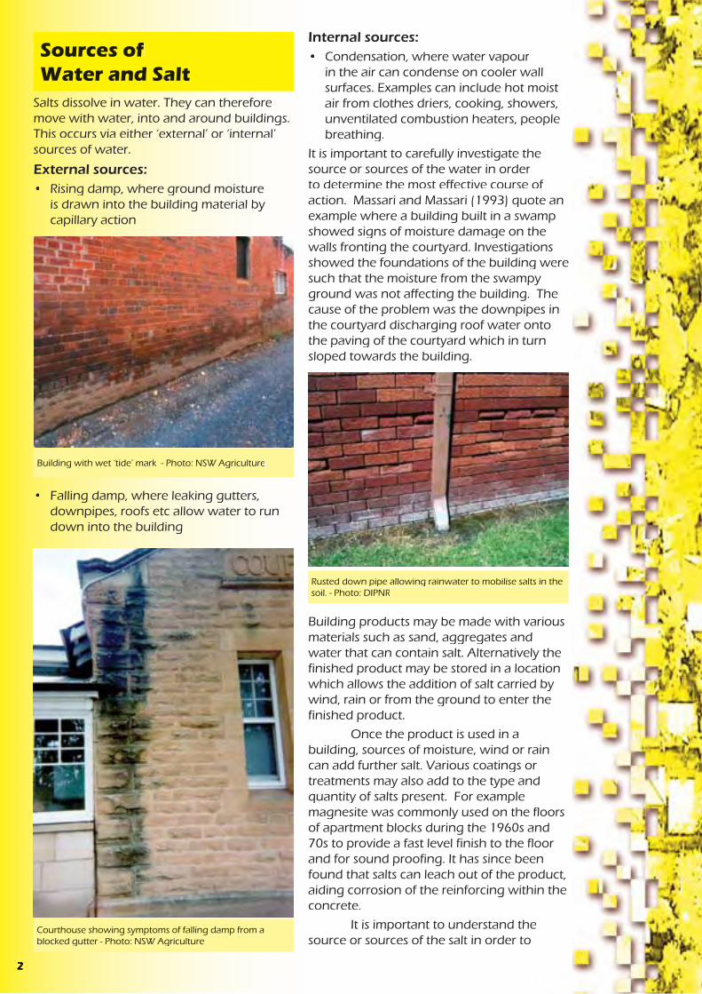
of the damp-proof course or termite barrier effectively providing a bridge for moisture or termites. Cutting the render at the height of the membrane is an ineffective solution. Over time, dust, dirt and salt crystals can easily bridge a small horizontal cut in the render.
• AS 3700 Masonry Structures, provides a table for durability requirements for exposure environments which includes the minimum salt attack resistance of masonry units, minimum mortar classification, minimum durability of built components and minimum cover to reinforcement.
• AS 2870 Residential Slabs and Footingspresently requires:
• a design life of 50 years (clause 1.4.2)
• drainage to be designed and constructed to avoid the ponding of water against or near footings. A graded fall of 50mm minimum away from the footing over a distance of 1m even on the ground uphill from the slab on cut and fill sites is required (clause 5.2.1)
• 40mm cover to reinforcement
• concrete to be vibrated and cured for at least 3 days in known salt damp areas (clause 6.4.8)
• careful detailing of damp-proof courses in high salt damp areas (clause 5.3.4)
• Damp-proof membranes to be extended under the edge beam to ground level ( clause 5.3.3.3)
and provides an advisory note to use damp-proof membranes in South Australia and areas prone to rising damp and salt attack (clause 5.3.2).
A committee was formed in early 2003 to review the requirements of this standard.
• AS 3600 Concrete Structures. This standard contains a detailed section on durability considerations.
Due to the levels of salts and water that accumulate over time in dryland salinity hazard areas it could be argued that the concrete requirements for moderately aggressive to aggressive environments detailed in AS 3600 should be considered for concrete structures. The following table compares the differences in requirements for the different environments.
These requirements are for a design life of 50 years yet in many cases it would be desirable to construct longer lasting homes and buildings.
Some of the construction and product standards have recommendations that can be overridden by professional expertise based on experience with the product. It is therefore important that members of the design and construction industry become more aware of the processes and impacts of urban salinity.
Non exposure grade bricks used in a garden wall
Photo: NSW Agriculture
non aggressive environment
B2 ( moderately aggressive environment)
C ( aggressive environment )
concrete strength 20M Pa 40M Pa 50M Pacuring time 3days 7days 7dayscover to reinforcing 40mm 45mm 50mm
Internal sources:• Condensation, where water vapour
in the air can condense on cooler wall surfaces. Examples can include hot moist air from clothes driers, cooking, showers, unventilated combustion heaters, people breathing.
It is important to carefully investigate the source or sources of the water in order to determine the most effective course of action. Massari and Massari (1993) quote an example where a building built in a swamp showed signs of moisture damage on the walls fronting the courtyard. Investigations showed the foundations of the building were such that the moisture from the swampy ground was not affecting the building. The cause of the problem was the downpipes in the courtyard discharging roof water onto the paving of the courtyard which in turn sloped towards the building.
Building products may be made with various materials such as sand, aggregates and water that can contain salt. Alternatively the finished product may be stored in a location which allows the addition of salt carried by wind, rain or from the ground to enter the finished product.
Once the product is used in a building, sources of moisture, wind or rain can add further salt. Various coatings or treatments may also add to the type and quantity of salts present. For example magnesite was commonly used on the floors of apartment blocks during the 1960s and 70s to provide a fast level finish to the floor and for sound proofing. It has since been found that salts can leach out of the product, aiding corrosion of the reinforcing within the concrete.
It is important to understand the source or sources of the salt in order to
Salts dissolve in water. They can therefore move with water, into and around buildings. This occurs via either ‘external’ or ‘internal’ sources of water.
External sources:• Rising damp, where ground moisture
is drawn into the building material by capillary action
• Falling damp, where leaking gutters, downpipes, roofs etc allow water to run down into the building
Sources of Water and Salt
Building with wet ‘tide’ mark - Photo: NSW Agriculture
Courthouse showing symptoms of falling damp from a blocked gutter - Photo: NSW Agriculture
Rusted down pipe allowing rainwater to mobilise salts in the soil. - Photo: DIPNR
2 15

Bricks efflorescing - Photo: NSW Agriculture
determine the most effective course of action, if action is needed. In some cases salt may appear as efflorescence on the surface of bricks as salts from the manufacturing process come to the surface. This may be a visual effect but does not cause structural damage to the building. In other cases the impact of salt may be less visible but more significant.
Infiltration RatesThe three main factors driving the rate of water entering a building are:
1. Amount of available water. This is influenced by the depth to the ground- water table, leaking water, sewer and stormwater systems, the over watering of gardens and the timing, distribution and intensity of rainfall.
2. Rate of evaporation. This is affected by such things as ventilation, temperature, relative humidity and the amount of building surface exposed.
3. Permeability of the building material. This depends on pore size, distribution and continuity of the pores within a building material.
Bricks exhibiting signs of salt and water damage
Photo: DIPNR
Porosity vs. PermeabilityA material may be porous but not permeable. That is, a material may have lots of pore spaces and therefore can hold a lot of water but at the same time not allow water to pass through it. If pores:
• are isolated or closed,
• have a lining that can react with fluid to discourage movement, or
• are too small to be filled as the air they contain cannot escape,
then the material will have a low permeability.
Pore size varies between materials but also within a material. In theory, a pore size of 0.001 mm can support a 1m high column of water. If salts are present in the water then the surface tension of the water is increased and there is increased ‘pull’ up the pore tube. This is partially offset by the increased weight of the water column due to the salts dissolved in the water. Pore diameters in mortar and brickwork are in the range of 0.1 um ( 0.0001 mm) to 10 um (0.01 mm). Fine cracks in concrete and other products can also act as capillary tubes. Therefore there is the potential for water to move a long way up a brick wall if the wall is exposed to a source of water.
• AS 4419 Soils For Landscaping and Garden Use sets a requirement for the appropriate labelling of low density and organic soils with an electrical conductivity of 2.5dS/m or 1.2dS/m for soil blends and natural soils. The labelling is to give clear information about salinity and the types of plants that will tolerate high salinity. There is also a note that expert advice should be sought as removal or dilution of salts depends on various factors such as the amount of salt present, depth and permeability of the soil.
This highlights the need to be careful when importing extra salts on to a site. Once present, salt is usually difficult to remove. This is not only important for plant growth and soil structure, but also for infrastructure. Unwashed sands, bricks made with salty clays, concrete made with salty bore water, or bore water used to suppress dust all import extra salt onto a site. Building materials stored on salty ground or exposed to salty winds or rain for extended periods may also pick up salts. Once concentrated within a building, salt may appear as efflorescence, cause corrosion to metals or cause physical and chemical damage to building materials even though the surrounding soil is showing low levels of salt. Many salts are hygroscopic, attracting water from sources such as dew. The salts are then easily mobilised within the structure causing the area of damage to increase until the salt is removed.
• AS 3798 Guidelines For Earthworks For Commercial and Residential Development contains various snippets of information that relate to salinity, for example:
• Site investigations should include identification of special areas relating to groundwater.
• Unsuitable materials for fill include those materials containing substances that can be dissolved or leached out [salt].
• Moisture content of fill should not be increased with saline water without field or laboratory trials. This should also be avoided in areas where steel will be buried or where revegetation will occur or areas that are to be later covered by bitumen.
• Special consideration of saline, chemically aggressive or polluted soils is needed to determine if they are suitable for fill.
• AS 3660.1 Termite Management - New Building Work, aims to deter the concealed entry of termites into new buildings above the termite barrier. However, as termites can damage soft concrete, enter through mortar joints and are attracted to damp areas, some of the recommendations for termite protection are also relevant for salinity protection. For example:
• Perimeter paths and areas under the house should be graded to prevent ponding.
• For slab on ground construction, concrete should be compacted and cured. This enhances the structural performance of the slab and increases resistance to penetration by termites.
• How to lay a barrier membrane to ensure the whole building is effectively protected without gaps.
• Finish a barrier membrane flush with the outside face of render rather than inside face.
Often render is applied over the edge
Typical earthworks on a residential building site
Photo: DIPNR
314
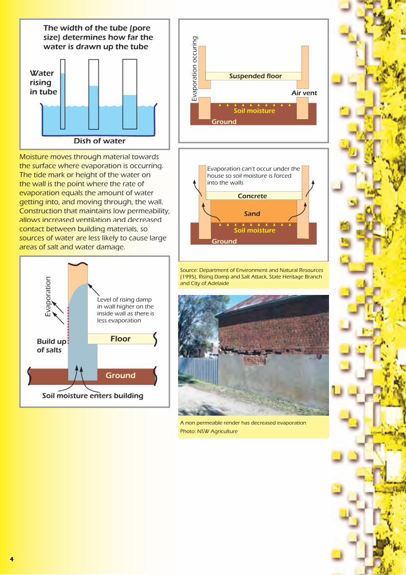
Moisture moves through material towards the surface where evaporation is occurring. The tide mark or height of the water on the wall is the point where the rate of evaporation equals the amount of water getting into, and moving through, the wall. Construction that maintains low permeability, allows increased ventilation and decreased contact between building materials, so sources of water are less likely to cause large areas of salt and water damage.
Source: Department of Environment and Natural Resources (1995), Rising Damp and Salt Attack, State Heritage Branch and City of Adelaide
A non permeable render has decreased evaporation
Photo: NSW Agriculture
with consideration to developing suitable requirements for buildings in saline areas. The Australian Building Codes Board (ABCB) has established a Technical Working Group to review and comment on salt attack documents and proposals as they are produced or acquired by the ABCB.
In South Australia there are currently three additional requirement for the barriers installed to prevent ground moisture entering the building:
• a high resistance to moisture penetration
• a high resistance to damage during construction and
• a high resistance to degradation by dissolved salts.
There are various Australian Standards that have provisions that assist in the management of salinity. For example:
• AS 1547 - 2000 On Site Domestic Waste Water Management has a performance requirement for on-site waste water systems to avoid surface and groundwater pollution. The standard recommends construction and installation is undertaken only after suitable site investigations that include such things as changes in the groundwater table and sodicity.
On-site waste water disposal adds extra salts to the soil as well as extra liquid to the groundwater system. This can result in on-site and off-site impacts if not properly considered. More information on salinity and effluent is provided in the Septic Safe Technical Reference Sheet published by the Department of Local Government, ‘Consideration of Soil Salinity When Assessing Land Application of Effluent’ by Dr Robert Patterson. More information on site investigations for salinity is provided in the Local Government Salinity Initiative booklet, ‘Site Investigations for Urban Salinity’ by the former Department of Land and Water Conservation. (2002)
• AS 2159 Piling Design and Installation provides table (6.1) Exposure Classification For Concrete Piles. Soil conditions are listed as non-aggressive, mild, moderate, severe or very severe, based on test results for pH, chlorides, sulphates and soil resistivity, for permeable soils which are below the groundwater table and for low permeability soils or all soils above the groundwater table. Various notes of caution are attached to the table such as the impact of magnesium or ammonium ions which, in the presence of sulphates, increase the aggressiveness of the soil on concrete. This standard also recommends site specific design of concrete for sulphate attack noting that dense, well compacted, low permeable concrete of the correct type is more important than a high characteristic strength.
Extracts from this standard are provided in the Local Government Salinity Initiative booklet, ‘Site Investigations for Urban Salinity’.
Australian Standards
Typical slab on ground construction. - Photo: DIPNR
134

ConcreteConcrete is a mixture of coarse and fine aggregate, cement and possibly additives such as fly ash, slag or chemical admixtures which enhance properties of the concrete for specific purposes. Although the aggregates are chemically reactive themselves, for example they can add alkalies and chlorides to the pore solution, it is the chemical properties of the cement that are more important.
Cement hardens through the chemical reaction of “hydration”, where water reacts chemically with the cement to form new compounds. The hydrated cement paste forms ribbon-like crystals that interlock and bind the sand and gravel to form concrete. The more interlocking and growth of crystals, the stronger and denser the concrete. Maintaining moisture in concrete during the curing period is essential in maintaining the process of hydration. However too much water in the mix or too little cement can result in weak concrete since the crystals can’t mesh and interlock well due to the distance between particles. The concrete will also be more porous due to all the pore spaces created once the excess water finally evaporates.
Once water and salt are absorbed by building materials, chemical and physical damage can result. The extent of chemical attack will depend on the concentrations and particular types of salts present as well as the composition of the building material.
Physical attack on the other hand requires a wetting and drying process. Salts form crystals as the moisture in which they are dissolved evaporates. A large crystal will exert physical pressure on the building material surrounding it. The next wet cycle allows the crystal to dissolve, move and later grow as more salts are supplied in the incoming water.
Different salts form different sized crystals, and even the same salt forms different sized crystals, under different conditions. These crystals can expand with heat. The effect on the building material will depend on the location of the crystal within the building material, as well as the physical properties and cohesive strength of the building material.
In a brick veneer building for example, evaporation is most likely to be highest on the outside wall of the northern side of the building. Higher levels of evaporation lead to a greater concentration of salt and more damage, provided there is a supply of salt and water. The outer surface, or fire skin, of the brick may be removed grain by grain by the force the salt crystals exert. This grain by grain removal increases the surface area of the brick, increases evaporation potential and also exposes the weaker interior of the brick. This process is called fretting.
The Reactions of Salts with Building Materials
Brick work showing the effects of fretting
Photo: NSW Agriculture
Brick work showing the effects of fretting and the accumulation of brick ‘grains’ at the base of the wall
Photo: DIPNR
Concrete being mixed on site - Photo:DIPNR
The Building Code of Australia (BCA) includes some requirements for building in saline environments. For example, in Volume 2 of the BCA, clauses 3.3.1.5(b), 3.3.1.6 and 3.3.1.7(b). The BCA also references Australian Standards that contain requirements for buildings in a saline environment. Some examples of these Standards (AS 2159, AS 2870, AS 3700 and AS 3600) are detailed in the next section of this booklet.
There are some inclusions that are aimed at providing protection against moisture in general. These include:
• Part of Objective 2.2 of the BCA is to protect the building from damage caused by external moisture entering a building.
• Functional Statement 2.2.2 Weatherproofing and Dampness, includes “construction to provide resistance to moisture from the outside and moisture rising from the ground”. This doesn’t apply to class 10 buildings unless construction contributes to the weatherproofing of a class 1 building. Class 1 buildings being residences and class 10 being outbuildings and associated structures such as verandahs, garages, swimming pools, flag poles and carparks.
• Performance Requirement P2.2.3 for Dampness relates specifically to moisture from the ground and requires prevention of
• unhealthy or dangerous conditions, or loss of amenity for occupants
• undue dampness or deterioration of building elements.
This performance requirement does not apply to a class 10 building where in the particular case it is judged that there is no necessity for compliance.
However, the current provisions contained in the BCA related to preventing dampness were not intended to provide protection against rising salt damp (salt attack/salinity) and were aimed at providing protection against moisture in general. At the Australian Building Code Board’s 2001 National Technical Summit, the issue of urban salinity was discussed and it was agreed that a review of the BCA requirements to prevent moisture penetration was necessary,
Water flow not obstructed by urban development
Diagram: DIPNR- Greener Subdivision project
Water flow obstructed by urban development
Diagram: DIPNR- Greener Subdivision project
The Building Code of Australia
512
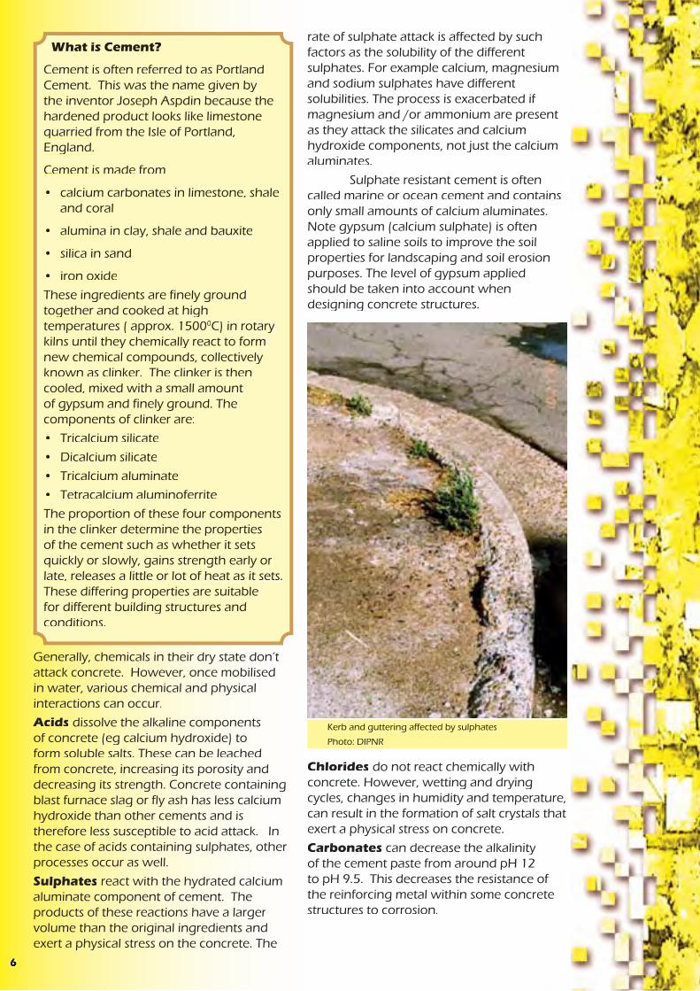
rate of sulphate attack is affected by such factors as the solubility of the different sulphates. For example calcium, magnesium and sodium sulphates have different solubilities. The process is exacerbated if magnesium and /or ammonium are present as they attack the silicates and calcium hydroxide components, not just the calcium aluminates.
Sulphate resistant cement is often called marine or ocean cement and contains only small amounts of calcium aluminates. Note gypsum (calcium sulphate) is often applied to saline soils to improve the soil properties for landscaping and soil erosion purposes. The level of gypsum applied should be taken into account when designing concrete structures.
Chlorides do not react chemically with concrete. However, wetting and drying cycles, changes in humidity and temperature, can result in the formation of salt crystals that exert a physical stress on concrete.
Carbonates can decrease the alkalinity of the cement paste from around pH 12 to pH 9.5. This decreases the resistance of the reinforcing metal within some concrete structures to corrosion.
Kerb and guttering affected by sulphates
Photo: DIPNR
Generally, chemicals in their dry state don’t attack concrete. However, once mobilised in water, various chemical and physical interactions can occur.
Acids dissolve the alkaline components of concrete (eg calcium hydroxide) to form soluble salts. These can be leached from concrete, increasing its porosity and decreasing its strength. Concrete containing blast furnace slag or fly ash has less calcium hydroxide than other cements and is therefore less susceptible to acid attack. In the case of acids containing sulphates, other processes occur as well.
Sulphates react with the hydrated calcium aluminate component of cement. The products of these reactions have a larger volume than the original ingredients and exert a physical stress on the concrete. The
What is Cement?
Cement is often referred to as Portland Cement. This was the name given by the inventor Joseph Aspdin because the hardened product looks like limestone quarried from the Isle of Portland, England.
Cement is made from
• calcium carbonates in limestone, shale and coral
• alumina in clay, shale and bauxite
• silica in sand
• iron oxide
These ingredients are finely ground together and cooked at high temperatures ( approx. 15000C) in rotary kilns until they chemically react to form new chemical compounds, collectively known as clinker. The clinker is then cooled, mixed with a small amount of gypsum and finely ground. The components of clinker are:
• Tricalcium silicate
• Dicalcium silicate
• Tricalcium aluminate
• Tetracalcium aluminoferrite
The proportion of these four components in the clinker determine the properties of the cement such as whether it sets quickly or slowly, gains strength early or late, releases a little or lot of heat as it sets. These differing properties are suitable for different building structures and conditions.
The movement of water at various scales needs to be considered with respect to the mobilisation of salt. On a catchment scale, water may be entering a groundwater system kilometres away from where the water returns to the surface. Along the way this water may have picked up salt from the rocks and soils it has passed through. In this situation, on-site action as well as work further up the catchment where the water is getting into the groundwater system could be more cost effective.
On a subdivision scale, decisions such as whether to use septic tanks, irrigate treated effluent, infiltrate stormwater, supply piped potable water, and how much native vegetation to retain, all impact on the salt and water movement. A salt and water balance should be undertaken to estimate the impact of the development on the salinity processes on and off site. If the environmental, social and economic costs are too high, an alternative decision should be made with respect to the aspect of the development causing the excess salt and water. Alternatively a long term monitoring, evaluation and management plan could be put in place to deal with potential adverse impacts.
On an individual house lot scale, construction and maintenance decisions such as:
• whether to cut or fill the site
• whether the ground is reshaped to slope away from the building
• how the site is landscaped
• how the landscaping is watered
• how much of the site is hard surfaces vs pervious surfaces
• whether a path is provided around the perimeter of the house and sloping away from the building
• what stormwater drainage is provided behind retaining walls
• whether pools, taps, and downpipes are regularly checked for leaks
all affect the amount of water on the site and how it is moving around the structure to be protected from salinity damage.
and areas prone to rising damp and salt attack. The extra cost is around $50 for a 140m2 house. Damp-proof membranes are more resistant to puncturing and stop water if there is no hydrostatic pressure.
Care should be taken when installing the damp-proof membrane to ensure it extends completely under the whole slab and up the sides to at least finished ground level. This prevents moisture moving in from the sides or through gaps. AS 2870 only permits ‘vapour’, not ‘damp’, barriers to be terminated at the internal face of external beams. The standard also sets requirements for the lapping of joints and taping of penetrations for pipes or plumbing fittings. However local plumbers and builders may not be aware of salinity hazard areas or of the importance of this work in such areas.
Care should also be taken laying the reinforcing and walking on the laid membrane prior to pouring of the concrete slab as these activities may result in small holes. Puncturing the membrane to allow excess water from the concrete to escape and speed up curing is also poor practice. Short curing times usually result in a more permeable concrete slab more susceptible to salt damp attack. If the water table is sufficiently high after construction or during the life of the building, then the puncture holes will allow moisture under the slab to move into the slab.
Maintaining Good Drainage on a Building Site
116

It is common practice at present in NSW to construct buildings with concrete floors essentially laying at ground level. Under the concrete slab, there is usually a layer of sand and a vapour-proof plastic that acts as the damp-proof course for the concrete slab. A damp-proof course is also installed in a mortar joint of the brickwork forming the walls of the building.
The sand layer provides a number of functions in relation to salinity. Firstly, it helps prevent membrane puncture from hard material in the underlaying soil. It also decreases the capillary rise of any soil moisture since the sand grains are quite far apart ie there are large pore spaces. Increasing this sand layer is one method that has been suggested1 to increase the protection of structures from salinity.
Previously, floors rested on bearers and joists, supported by piers. This type of construction has less building material in contact with possible salt and water sources in the ground. It more readily allows ventilation, evaporation and the concentration of salts to occur in the soil rather than building materials. It is also less likely to impact on natural salt and water processes.
The Australian building code presently requires a minimum clearance of 400mm between the ground and suspended floors to allow ease of access for termite inspection. This also allows a visual inspection for salinity damage to piers.
A damp-proof membrane should be laid under concrete slabs and marked “ AS 2870 concrete underlay, 0.2 mm High impact resistance”. A vapour-proof plastic layer used under concrete slabs should be printed with the words “AS 2870 concrete underlay, 0.2 mm - Medium impact resistance”. The Building Code of Australia recommends damp-proof membranes in South Australia
Damp-proof course has been bypassed by rendering
Photo: NSW Agriculture
Damp-proof course limiting damage to lower three bricks
Photo: DIPNR
Damage discovered during a building inspection
1 Wagga Wagga City Council, 1999 Building In A Saline Environment and Lume E. (1998), Concrete In Saline Groundwater Environments, Cement and Concrete Association of Australia,
The South Australian Salt Damp Research Committee, in their Second Report (1978), stated, “ Protection against salt damp is dependent upon each link in a continuous chain - competent design and specifications, painstaking construction, skilled supervision, good housekeeping and maintenance by the owner/occupier”. It is logical that this theory holds true today.
The location of the DPC is also important.
Corrosion of reinforcement in concreteoccurs in 2 phases, namely initiation and propagation. The initiation phase occurs when the alkalinity of the concrete is reduced by carbonation or ionization. Carbonates may come from sources such as groundwater or carbon dioxide in the air. Ionization occurs where there is a higher concentration of reactive ions such as chlorides. Chlorides may come from groundwater, the atmosphere, acid etching, admixtures, or the water, aggregate and sand used to make the concrete. Once initiated, the propagation phase of the corrosion continues at a rate dependent on the amount of available oxygen, moisture, reactive ions and remaining alkalinity.
It is therefore important to know the site conditions and chemicals that the building will be exposed to, so that a suitable type of building material can be chosen and installed. Careful site supervision and quality control is then required to ensure consistency in the production of mortar and other products mixed on site or at batching plants.
Reinforcing steel exposed and corrodingPhoto: DIPNR
Bricks that are less susceptible to damage from salt and water:
• are less permeable so the salt and water cannot penetrate
• do not contain excessive amounts of salts, thus are not adding more salt to the process
• have good internal strength so that they can withstand the physical stress created by the formation of salt crystals
The Building Code of Australia (BCA), Part 3.3.1, requires masonry units to be classified and used in the exposure conditions appropriate to their classification. Table 3.3.1.1 of the BCA states exposure class is “Suitable for use in all classifications including severe local conditions such as:
a) below the damp-proof course in areas where walls are expected to be attacked by salts in the groundwater or brickwork itself ( salt attack or salt damp)
.....
c) In retaining walls.”
The BCA also gives the ratio of cement, lime and sand suitable for mortars, prohibits raked mortar joints in areas requiring exposure class bricks, and requires mortar to be made with potable, not salty, water.
Methods to test the properties of bricks can be found in Australian Standards. Australian Standard 4456.6 Masonry Units and Segmental Pavers - Methods of Test - Determining Potential To Effloresce, compares couples of masonry units where one brick of the pair has been soaked in water for 7 days and then air dried, and the other brick is untreated. A ranking is then given to each batch of bricks ( nil, slight, moderate, heavy or severe) based on
Bricks Resistant to Salt and Water
710

the amount of efflorescence on the outer surface of the treated unit. This test gives an indication of the amount of salt accumulated in the brick from the production and storage process.
Australian Standard 4456.1 Masonry Units and Segmental Pavers - Method of Determining Resistance to Salt Attack, is a test that is used to classify a brick’s resistance to salt attack. Bricks are soaked in a salt solution of either sodium sulphate or sodium chloride and then dried. This is repeated up to 40 times and the amount of damage assessed by comparing the weight of the bricks before and after the process. Bricks are then rated as ‘exposure’, ‘protected’ or ‘general purpose’ class. Satisfactory performance of a sample in a sodium sulphate solution usually guarantees satisfactory performance in a sodium chloride solution but not vice versa. This is presumably due to the sulphate chemical reactions mentioned previously.
Concrete Resistant to Salt and Water
Durability of concrete depends on internal factors such as constituents as well as external factors such as design and construction.
Permeability is a very important factor with regard to rising damp. The more permeable the concrete, the less durable it will be. Permeability depends on pore size, pore distribution and the continuity of pores. Voids are formed by excess water in the mix, incomplete compaction, and incomplete curing which allows concrete to dry out prematurely.
In order to improve the durability of concrete in moist saline environments, consider:
• Proper compaction of the concrete
• Reducing the water cement ratio
• Proper curing procedures and duration
• Choice of appropriate concrete materials (ie cement type, sands and aggregate) for the site conditions
• Increasing the concrete cover over steel reinforcement
• Minimising cracks
• Minimising ponding of water on or next to concrete
• Minimising turbulence of any water flowing over a concrete structure
• A smooth surface
• Increasing the cement content
• Using a quality assurance certified supplier
All other factors being equal, increasing the strength of concrete will decrease its permeability. As there is no standard test for permeability in cement, strength is often used as an ‘indicator’ of permeability. However, this is an oversimplification and should not be used as the only specification or design criteria for ensuring concrete structures are durable in salinity hazard landscapes.
A damp-proof course is a layer of water impermeable material commonly installed in buildings close to ground level. In the past, damp-proof courses have been made of various materials including coal tar, slate, metal and mortars containing chimney soot. Today, it is common for the damp proof course to be a polyethylene sheeting laid in a mortar joint of the brick work.
A damp-proof course should restrict any damage from rising damp to the area below the damp-proof course. However, a damp- proof course (DPC) may:
• break down due to chemical decomposition
• be cracked or penetrated during installation
• be broken by the differential settling of the building
• be incorrectly installed
• be bridged by pointing or rendering
• be bridged by the installation of garden beds and paving
• be bridged by mortar droppings in the wall cavity
• be bridged by renovations or additions, eg incorrect replacement of a timber floor with sand and a concrete slab
Once the damp-proof course is bridged or broken, water and any salts it contains are able to move upwards. This significantly increases the difficulty and cost of repairing salinity damage to buildings. Correctly installing and maintaining a durable damp- proof course is therefore an important technique in controlling salt damage to buildings.
Preventing Salt and Water Moving into the Building
Installation of polyethylene sheeting in mortar joint of the brick work - Photo: DIPNR
Source: Department of Environment and Natural Resources (1995), Rising Damp and Salt Attack, State Heritage Branch and City Of Adelaide.
98
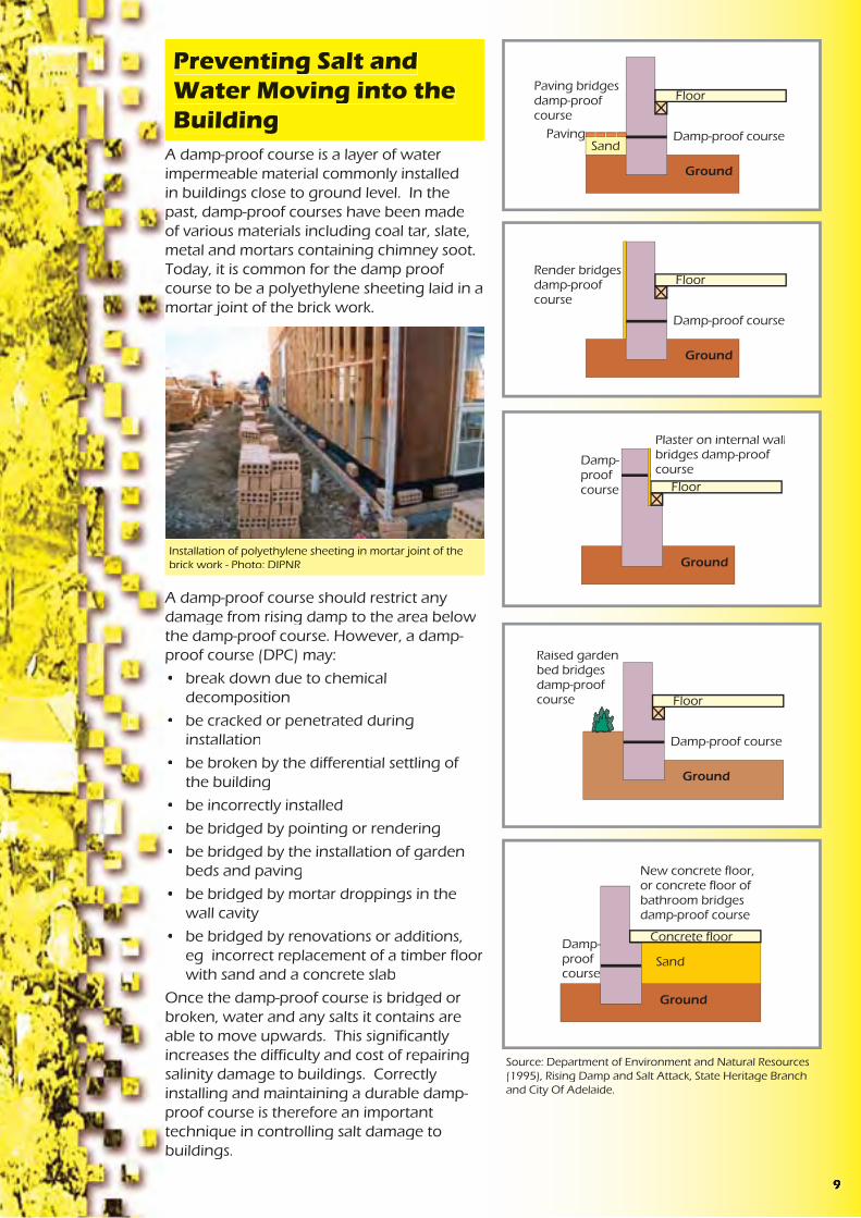

It is common practice at present in NSW to construct buildings with concrete floors essentially laying at ground level. Under the concrete slab, there is usually a layer of sand and a vapour-proof plastic that acts as the damp-proof course for the concrete slab. A damp-proof course is also installed in a mortar joint of the brickwork forming the walls of the building.
The sand layer provides a number of functions in relation to salinity. Firstly, it helps prevent membrane puncture from hard material in the underlaying soil. It also decreases the capillary rise of any soil moisture since the sand grains are quite far apart ie there are large pore spaces. Increasing this sand layer is one method that has been suggested1 to increase the protection of structures from salinity.
Previously, floors rested on bearers and joists, supported by piers. This type of construction has less building material in contact with possible salt and water sources in the ground. It more readily allows ventilation, evaporation and the concentration of salts to occur in the soil rather than building materials. It is also less likely to impact on natural salt and water processes.
The Australian building code presently requires a minimum clearance of 400mm between the ground and suspended floors to allow ease of access for termite inspection. This also allows a visual inspection for salinity damage to piers.
A damp-proof membrane should be laid under concrete slabs and marked “ AS 2870 concrete underlay, 0.2 mm High impact resistance”. A vapour-proof plastic layer used under concrete slabs should be printed with the words “AS 2870 concrete underlay, 0.2 mm - Medium impact resistance”. The Building Code of Australia recommends damp-proof membranes in South Australia
Damp-proof course has been bypassed by rendering
Photo: NSW Agriculture
Damp-proof course limiting damage to lower three bricks
Photo: DIPNR
Damage discovered during a building inspection
1 Wagga Wagga City Council, 1999 Building In A Saline Environment and Lume E. (1998), Concrete In Saline Groundwater Environments, Cement and Concrete Association of Australia,
The South Australian Salt Damp Research Committee, in their Second Report (1978), stated, “ Protection against salt damp is dependent upon each link in a continuous chain - competent design and specifications, painstaking construction, skilled supervision, good housekeeping and maintenance by the owner/occupier”. It is logical that this theory holds true today.
The location of the DPC is also important.
Corrosion of reinforcement in concreteoccurs in 2 phases, namely initiation and propagation. The initiation phase occurs when the alkalinity of the concrete is reduced by carbonation or ionization. Carbonates may come from sources such as groundwater or carbon dioxide in the air. Ionization occurs where there is a higher concentration of reactive ions such as chlorides. Chlorides may come from groundwater, the atmosphere, acid etching, admixtures, or the water, aggregate and sand used to make the concrete. Once initiated, the propagation phase of the corrosion continues at a rate dependent on the amount of available oxygen, moisture, reactive ions and remaining alkalinity.
It is therefore important to know the site conditions and chemicals that the building will be exposed to, so that a suitable type of building material can be chosen and installed. Careful site supervision and quality control is then required to ensure consistency in the production of mortar and other products mixed on site or at batching plants.
Reinforcing steel exposed and corrodingPhoto: DIPNR
Bricks that are less susceptible to damage from salt and water:
• are less permeable so the salt and water cannot penetrate
• do not contain excessive amounts of salts, thus are not adding more salt to the process
• have good internal strength so that they can withstand the physical stress created by the formation of salt crystals
The Building Code of Australia (BCA), Part 3.3.1, requires masonry units to be classified and used in the exposure conditions appropriate to their classification. Table 3.3.1.1 of the BCA states exposure class is “Suitable for use in all classifications including severe local conditions such as:
a) below the damp-proof course in areas where walls are expected to be attacked by salts in the groundwater or brickwork itself ( salt attack or salt damp)
.....
c) In retaining walls.”
The BCA also gives the ratio of cement, lime and sand suitable for mortars, prohibits raked mortar joints in areas requiring exposure class bricks, and requires mortar to be made with potable, not salty, water.
Methods to test the properties of bricks can be found in Australian Standards. Australian Standard 4456.6 Masonry Units and Segmental Pavers - Methods of Test - Determining Potential To Effloresce, compares couples of masonry units where one brick of the pair has been soaked in water for 7 days and then air dried, and the other brick is untreated. A ranking is then given to each batch of bricks ( nil, slight, moderate, heavy or severe) based on
Bricks Resistant to Salt and Water
710

rate of sulphate attack is affected by such factors as the solubility of the different sulphates. For example calcium, magnesium and sodium sulphates have different solubilities. The process is exacerbated if magnesium and /or ammonium are present as they attack the silicates and calcium hydroxide components, not just the calcium aluminates.
Sulphate resistant cement is often called marine or ocean cement and contains only small amounts of calcium aluminates. Note gypsum (calcium sulphate) is often applied to saline soils to improve the soil properties for landscaping and soil erosion purposes. The level of gypsum applied should be taken into account when designing concrete structures.
Chlorides do not react chemically with concrete. However, wetting and drying cycles, changes in humidity and temperature, can result in the formation of salt crystals that exert a physical stress on concrete.
Carbonates can decrease the alkalinity of the cement paste from around pH 12 to pH 9.5. This decreases the resistance of the reinforcing metal within some concrete structures to corrosion.
Kerb and guttering affected by sulphates
Photo: DIPNR
Generally, chemicals in their dry state don’t attack concrete. However, once mobilised in water, various chemical and physical interactions can occur.
Acids dissolve the alkaline components of concrete (eg calcium hydroxide) to form soluble salts. These can be leached from concrete, increasing its porosity and decreasing its strength. Concrete containing blast furnace slag or fly ash has less calcium hydroxide than other cements and is therefore less susceptible to acid attack. In the case of acids containing sulphates, other processes occur as well.
Sulphates react with the hydrated calcium aluminate component of cement. The products of these reactions have a larger volume than the original ingredients and exert a physical stress on the concrete. The
What is Cement?
Cement is often referred to as Portland Cement. This was the name given by the inventor Joseph Aspdin because the hardened product looks like limestone quarried from the Isle of Portland, England.
Cement is made from
• calcium carbonates in limestone, shale and coral
• alumina in clay, shale and bauxite
• silica in sand
• iron oxide
These ingredients are finely ground together and cooked at high temperatures ( approx. 15000C) in rotary kilns until they chemically react to form new chemical compounds, collectively known as clinker. The clinker is then cooled, mixed with a small amount of gypsum and finely ground. The components of clinker are:
• Tricalcium silicate
• Dicalcium silicate
• Tricalcium aluminate
• Tetracalcium aluminoferrite
The proportion of these four components in the clinker determine the properties of the cement such as whether it sets quickly or slowly, gains strength early or late, releases a little or lot of heat as it sets. These differing properties are suitable for different building structures and conditions.
The movement of water at various scales needs to be considered with respect to the mobilisation of salt. On a catchment scale, water may be entering a groundwater system kilometres away from where the water returns to the surface. Along the way this water may have picked up salt from the rocks and soils it has passed through. In this situation, on-site action as well as work further up the catchment where the water is getting into the groundwater system could be more cost effective.
On a subdivision scale, decisions such as whether to use septic tanks, irrigate treated effluent, infiltrate stormwater, supply piped potable water, and how much native vegetation to retain, all impact on the salt and water movement. A salt and water balance should be undertaken to estimate the impact of the development on the salinity processes on and off site. If the environmental, social and economic costs are too high, an alternative decision should be made with respect to the aspect of the development causing the excess salt and water. Alternatively a long term monitoring, evaluation and management plan could be put in place to deal with potential adverse impacts.
On an individual house lot scale, construction and maintenance decisions such as:
• whether to cut or fill the site
• whether the ground is reshaped to slope away from the building
• how the site is landscaped
• how the landscaping is watered
• how much of the site is hard surfaces vs pervious surfaces
• whether a path is provided around the perimeter of the house and sloping away from the building
• what stormwater drainage is provided behind retaining walls
• whether pools, taps, and downpipes are regularly checked for leaks
all affect the amount of water on the site and how it is moving around the structure to be protected from salinity damage.
and areas prone to rising damp and salt attack. The extra cost is around $50 for a 140m2 house. Damp-proof membranes are more resistant to puncturing and stop water if there is no hydrostatic pressure.
Care should be taken when installing the damp-proof membrane to ensure it extends completely under the whole slab and up the sides to at least finished ground level. This prevents moisture moving in from the sides or through gaps. AS 2870 only permits ‘vapour’, not ‘damp’, barriers to be terminated at the internal face of external beams. The standard also sets requirements for the lapping of joints and taping of penetrations for pipes or plumbing fittings. However local plumbers and builders may not be aware of salinity hazard areas or of the importance of this work in such areas.
Care should also be taken laying the reinforcing and walking on the laid membrane prior to pouring of the concrete slab as these activities may result in small holes. Puncturing the membrane to allow excess water from the concrete to escape and speed up curing is also poor practice. Short curing times usually result in a more permeable concrete slab more susceptible to salt damp attack. If the water table is sufficiently high after construction or during the life of the building, then the puncture holes will allow moisture under the slab to move into the slab.
Maintaining Good Drainage on a Building Site
116

ConcreteConcrete is a mixture of coarse and fine aggregate, cement and possibly additives such as fly ash, slag or chemical admixtures which enhance properties of the concrete for specific purposes. Although the aggregates are chemically reactive themselves, for example they can add alkalies and chlorides to the pore solution, it is the chemical properties of the cement that are more important.
Cement hardens through the chemical reaction of “hydration”, where water reacts chemically with the cement to form new compounds. The hydrated cement paste forms ribbon-like crystals that interlock and bind the sand and gravel to form concrete. The more interlocking and growth of crystals, the stronger and denser the concrete. Maintaining moisture in concrete during the curing period is essential in maintaining the process of hydration. However too much water in the mix or too little cement can result in weak concrete since the crystals can’t mesh and interlock well due to the distance between particles. The concrete will also be more porous due to all the pore spaces created once the excess water finally evaporates.
Once water and salt are absorbed by building materials, chemical and physical damage can result. The extent of chemical attack will depend on the concentrations and particular types of salts present as well as the composition of the building material.
Physical attack on the other hand requires a wetting and drying process. Salts form crystals as the moisture in which they are dissolved evaporates. A large crystal will exert physical pressure on the building material surrounding it. The next wet cycle allows the crystal to dissolve, move and later grow as more salts are supplied in the incoming water.
Different salts form different sized crystals, and even the same salt forms different sized crystals, under different conditions. These crystals can expand with heat. The effect on the building material will depend on the location of the crystal within the building material, as well as the physical properties and cohesive strength of the building material.
In a brick veneer building for example, evaporation is most likely to be highest on the outside wall of the northern side of the building. Higher levels of evaporation lead to a greater concentration of salt and more damage, provided there is a supply of salt and water. The outer surface, or fire skin, of the brick may be removed grain by grain by the force the salt crystals exert. This grain by grain removal increases the surface area of the brick, increases evaporation potential and also exposes the weaker interior of the brick. This process is called fretting.
The Reactions of Salts with Building Materials
Brick work showing the effects of fretting
Photo: NSW Agriculture
Brick work showing the effects of fretting and the accumulation of brick ‘grains’ at the base of the wall
Photo: DIPNR
Concrete being mixed on site - Photo:DIPNR
The Building Code of Australia (BCA) includes some requirements for building in saline environments. For example, in Volume 2 of the BCA, clauses 3.3.1.5(b), 3.3.1.6 and 3.3.1.7(b). The BCA also references Australian Standards that contain requirements for buildings in a saline environment. Some examples of these Standards (AS 2159, AS 2870, AS 3700 and AS 3600) are detailed in the next section of this booklet.
There are some inclusions that are aimed at providing protection against moisture in general. These include:
• Part of Objective 2.2 of the BCA is to protect the building from damage caused by external moisture entering a building.
• Functional Statement 2.2.2 Weatherproofing and Dampness, includes “construction to provide resistance to moisture from the outside and moisture rising from the ground”. This doesn’t apply to class 10 buildings unless construction contributes to the weatherproofing of a class 1 building. Class 1 buildings being residences and class 10 being outbuildings and associated structures such as verandahs, garages, swimming pools, flag poles and carparks.
• Performance Requirement P2.2.3 for Dampness relates specifically to moisture from the ground and requires prevention of
• unhealthy or dangerous conditions, or loss of amenity for occupants
• undue dampness or deterioration of building elements.
This performance requirement does not apply to a class 10 building where in the particular case it is judged that there is no necessity for compliance.
However, the current provisions contained in the BCA related to preventing dampness were not intended to provide protection against rising salt damp (salt attack/salinity) and were aimed at providing protection against moisture in general. At the Australian Building Code Board’s 2001 National Technical Summit, the issue of urban salinity was discussed and it was agreed that a review of the BCA requirements to prevent moisture penetration was necessary,
Water flow not obstructed by urban development
Diagram: DIPNR- Greener Subdivision project
Water flow obstructed by urban development
Diagram: DIPNR- Greener Subdivision project
The Building Code of Australia
512

Moisture moves through material towards the surface where evaporation is occurring. The tide mark or height of the water on the wall is the point where the rate of evaporation equals the amount of water getting into, and moving through, the wall. Construction that maintains low permeability, allows increased ventilation and decreased contact between building materials, so sources of water are less likely to cause large areas of salt and water damage.
Source: Department of Environment and Natural Resources (1995), Rising Damp and Salt Attack, State Heritage Branch and City of Adelaide
A non permeable render has decreased evaporation
Photo: NSW Agriculture
with consideration to developing suitable requirements for buildings in saline areas. The Australian Building Codes Board (ABCB) has established a Technical Working Group to review and comment on salt attack documents and proposals as they are produced or acquired by the ABCB.
In South Australia there are currently three additional requirement for the barriers installed to prevent ground moisture entering the building:
• a high resistance to moisture penetration
• a high resistance to damage during construction and
• a high resistance to degradation by dissolved salts.
There are various Australian Standards that have provisions that assist in the management of salinity. For example:
• AS 1547 - 2000 On Site Domestic Waste Water Management has a performance requirement for on-site waste water systems to avoid surface and groundwater pollution. The standard recommends construction and installation is undertaken only after suitable site investigations that include such things as changes in the groundwater table and sodicity.
On-site waste water disposal adds extra salts to the soil as well as extra liquid to the groundwater system. This can result in on-site and off-site impacts if not properly considered. More information on salinity and effluent is provided in the Septic Safe Technical Reference Sheet published by the Department of Local Government, ‘Consideration of Soil Salinity When Assessing Land Application of Effluent’ by Dr Robert Patterson. More information on site investigations for salinity is provided in the Local Government Salinity Initiative booklet, ‘Site Investigations for Urban Salinity’ by the former Department of Land and Water Conservation. (2002)
• AS 2159 Piling Design and Installation provides table (6.1) Exposure Classification For Concrete Piles. Soil conditions are listed as non-aggressive, mild, moderate, severe or very severe, based on test results for pH, chlorides, sulphates and soil resistivity, for permeable soils which are below the groundwater table and for low permeability soils or all soils above the groundwater table. Various notes of caution are attached to the table such as the impact of magnesium or ammonium ions which, in the presence of sulphates, increase the aggressiveness of the soil on concrete. This standard also recommends site specific design of concrete for sulphate attack noting that dense, well compacted, low permeable concrete of the correct type is more important than a high characteristic strength.
Extracts from this standard are provided in the Local Government Salinity Initiative booklet, ‘Site Investigations for Urban Salinity’.
Australian Standards
Typical slab on ground construction. - Photo: DIPNR
134

Bricks efflorescing - Photo: NSW Agriculture
determine the most effective course of action, if action is needed. In some cases salt may appear as efflorescence on the surface of bricks as salts from the manufacturing process come to the surface. This may be a visual effect but does not cause structural damage to the building. In other cases the impact of salt may be less visible but more significant.
Infiltration RatesThe three main factors driving the rate of water entering a building are:
1. Amount of available water. This is influenced by the depth to the ground- water table, leaking water, sewer and stormwater systems, the over watering of gardens and the timing, distribution and intensity of rainfall.
2. Rate of evaporation. This is affected by such things as ventilation, temperature, relative humidity and the amount of building surface exposed.
3. Permeability of the building material. This depends on pore size, distribution and continuity of the pores within a building material.
Bricks exhibiting signs of salt and water damage
Photo: DIPNR
Porosity vs. PermeabilityA material may be porous but not permeable. That is, a material may have lots of pore spaces and therefore can hold a lot of water but at the same time not allow water to pass through it. If pores:
• are isolated or closed,
• have a lining that can react with fluid to discourage movement, or
• are too small to be filled as the air they contain cannot escape,
then the material will have a low permeability.
Pore size varies between materials but also within a material. In theory, a pore size of 0.001 mm can support a 1m high column of water. If salts are present in the water then the surface tension of the water is increased and there is increased ‘pull’ up the pore tube. This is partially offset by the increased weight of the water column due to the salts dissolved in the water. Pore diameters in mortar and brickwork are in the range of 0.1 um ( 0.0001 mm) to 10 um (0.01 mm). Fine cracks in concrete and other products can also act as capillary tubes. Therefore there is the potential for water to move a long way up a brick wall if the wall is exposed to a source of water.
• AS 4419 Soils For Landscaping and Garden Use sets a requirement for the appropriate labelling of low density and organic soils with an electrical conductivity of 2.5dS/m or 1.2dS/m for soil blends and natural soils. The labelling is to give clear information about salinity and the types of plants that will tolerate high salinity. There is also a note that expert advice should be sought as removal or dilution of salts depends on various factors such as the amount of salt present, depth and permeability of the soil.
This highlights the need to be careful when importing extra salts on to a site. Once present, salt is usually difficult to remove. This is not only important for plant growth and soil structure, but also for infrastructure. Unwashed sands, bricks made with salty clays, concrete made with salty bore water, or bore water used to suppress dust all import extra salt onto a site. Building materials stored on salty ground or exposed to salty winds or rain for extended periods may also pick up salts. Once concentrated within a building, salt may appear as efflorescence, cause corrosion to metals or cause physical and chemical damage to building materials even though the surrounding soil is showing low levels of salt. Many salts are hygroscopic, attracting water from sources such as dew. The salts are then easily mobilised within the structure causing the area of damage to increase until the salt is removed.
• AS 3798 Guidelines For Earthworks For Commercial and Residential Development contains various snippets of information that relate to salinity, for example:
• Site investigations should include identification of special areas relating to groundwater.
• Unsuitable materials for fill include those materials containing substances that can be dissolved or leached out [salt].
• Moisture content of fill should not be increased with saline water without field or laboratory trials. This should also be avoided in areas where steel will be buried or where revegetation will occur or areas that are to be later covered by bitumen.
• Special consideration of saline, chemically aggressive or polluted soils is needed to determine if they are suitable for fill.
• AS 3660.1 Termite Management - New Building Work, aims to deter the concealed entry of termites into new buildings above the termite barrier. However, as termites can damage soft concrete, enter through mortar joints and are attracted to damp areas, some of the recommendations for termite protection are also relevant for salinity protection. For example:
• Perimeter paths and areas under the house should be graded to prevent ponding.
• For slab on ground construction, concrete should be compacted and cured. This enhances the structural performance of the slab and increases resistance to penetration by termites.
• How to lay a barrier membrane to ensure the whole building is effectively protected without gaps.
• Finish a barrier membrane flush with the outside face of render rather than inside face.
Often render is applied over the edge
Typical earthworks on a residential building site
Photo: DIPNR
314

of the damp-proof course or termite barrier effectively providing a bridge for moisture or termites. Cutting the render at the height of the membrane is an ineffective solution. Over time, dust, dirt and salt crystals can easily bridge a small horizontal cut in the render.
• AS 3700 Masonry Structures, provides a table for durability requirements for exposure environments which includes the minimum salt attack resistance of masonry units, minimum mortar classification, minimum durability of built components and minimum cover to reinforcement.
• AS 2870 Residential Slabs and Footingspresently requires:
• a design life of 50 years (clause 1.4.2)
• drainage to be designed and constructed to avoid the ponding of water against or near footings. A graded fall of 50mm minimum away from the footing over a distance of 1m even on the ground uphill from the slab on cut and fill sites is required (clause 5.2.1)
• 40mm cover to reinforcement
• concrete to be vibrated and cured for at least 3 days in known salt damp areas (clause 6.4.8)
• careful detailing of damp-proof courses in high salt damp areas (clause 5.3.4)
• Damp-proof membranes to be extended under the edge beam to ground level ( clause 5.3.3.3)
and provides an advisory note to use damp-proof membranes in South Australia and areas prone to rising damp and salt attack (clause 5.3.2).
A committee was formed in early 2003 to review the requirements of this standard.
• AS 3600 Concrete Structures. This standard contains a detailed section on durability considerations.
Due to the levels of salts and water that accumulate over time in dryland salinity hazard areas it could be argued that the concrete requirements for moderately aggressive to aggressive environments detailed in AS 3600 should be considered for concrete structures. The following table compares the differences in requirements for the different environments.
These requirements are for a design life of 50 years yet in many cases it would be desirable to construct longer lasting homes and buildings.
Some of the construction and product standards have recommendations that can be overridden by professional expertise based on experience with the product. It is therefore important that members of the design and construction industry become more aware of the processes and impacts of urban salinity.
Non exposure grade bricks used in a garden wall
Photo: NSW Agriculture
non aggressive environment
B2 ( moderately aggressive environment)
C ( aggressive environment )
concrete strength 20M Pa 40M Pa 50M Pacuring time 3days 7days 7dayscover to reinforcing 40mm 45mm 50mm
Internal sources:• Condensation, where water vapour
in the air can condense on cooler wall surfaces. Examples can include hot moist air from clothes driers, cooking, showers, unventilated combustion heaters, people breathing.
It is important to carefully investigate the source or sources of the water in order to determine the most effective course of action. Massari and Massari (1993) quote an example where a building built in a swamp showed signs of moisture damage on the walls fronting the courtyard. Investigations showed the foundations of the building were such that the moisture from the swampy ground was not affecting the building. The cause of the problem was the downpipes in the courtyard discharging roof water onto the paving of the courtyard which in turn sloped towards the building.
Building products may be made with various materials such as sand, aggregates and water that can contain salt. Alternatively the finished product may be stored in a location which allows the addition of salt carried by wind, rain or from the ground to enter the finished product.
Once the product is used in a building, sources of moisture, wind or rain can add further salt. Various coatings or treatments may also add to the type and quantity of salts present. For example magnesite was commonly used on the floors of apartment blocks during the 1960s and 70s to provide a fast level finish to the floor and for sound proofing. It has since been found that salts can leach out of the product, aiding corrosion of the reinforcing within the concrete.
It is important to understand the source or sources of the salt in order to
Salts dissolve in water. They can therefore move with water, into and around buildings. This occurs via either ‘external’ or ‘internal’ sources of water.
External sources:• Rising damp, where ground moisture
is drawn into the building material by capillary action
• Falling damp, where leaking gutters, downpipes, roofs etc allow water to run down into the building
Sources of Water and Salt
Building with wet ‘tide’ mark - Photo: NSW Agriculture
Courthouse showing symptoms of falling damp from a blocked gutter - Photo: NSW Agriculture
Rusted down pipe allowing rainwater to mobilise salts in the soil. - Photo: DIPNR
2 15

Salts are a natural part of the Australian landscape. Concentrated salt and different types of salt, once dissolved and mobilised in water, can have an impact on the durability of some building material. This booklet looks at:
1. how salts get into building material
2. the effect salt and water can have on some building materials.
Through the explanation of the processes, ideas are given on how to build structures that are less susceptible to salt damage. Other booklets of the Local Government Salinity Initiative kit, ‘Broad Scale Resources For Urban Salinity Assessment’ and ‘Site Investigations For Urban Salinity’, can be used to determine if salty groundwater or salty soil are likely to be affecting a building. ‘Indicators Of Urban Salinity’, gives a guide to the range of symptoms salt and water damage can create in an urban environment. ‘Roads and Salinity’ looks at how to construct a road so that it resists the effects of salinity and does not adversely impact on salt and water processes.
Render showing signs that excess salt and water are present
Photo: NSW Agriculture
Bricks showing signs of salt and water damage
Photo: NSW Agriculture
Paintwork blistering due to the accumulation of salt
Photo: DIPNR
Sandstone showing signs of salt and water damage
Photo: NSW Agriculture
Introduction
Verandah post showing signs of salt and water damage
Salinity and the Electricity Industry
Concrete poles are being used increasingly within the electricity supply industry because of their low maintenance requirements, long life and cost effectiveness. These power poles are often constructed of concrete with internal steel reinforcing. Rust stains, cracking and spalling of the concrete have been observed in situations where the alkalinity of the concrete and the cover of the concrete over the steel reinforcing have not been adequate to protect the internal steel from corrosion. This corrosion is caused by saline soils, galvanic couples between the reinforcing steel and dissimilar metals, and stray direct electric current.
Since the late 1960s it has become common practice for steel structures in the electricity industry to have their foundations encased in concrete in order to limit corrosion. Concrete cover of at least 70mm is recommended.
Source: Electricity Association of NSW, (1997), Corrosion
In The Electricity Supply Industry
Electricity supply pole with salinity vegetation indicators
Photo:DIPNR
116

© Department of Infrastructure, Planning and Natural Resources 2003Department of Infrastructure, Planning and Natural Resources 2003
This booklet is copy under the Berne Convention All rights reserved No reproduction without permission
First published 2003 Department of Infrastructure, Planning and Natural Resources22-33 Bridge Street Sydney NSW 2000
Building in a Saline EnvironmentISBN: 0 7347 5375 6Designed and printed by ClickMedia, Penrith Photographs: various sources
American Concrete Institute, A Guide To The Use Of Waterproofing, Damp proofing, Protective and Decorative Barriers Systems For Concrete, American Concrete Institute, Detroit, Michigan.
Andrews-Phaedonos, F ( 1997) The Effects Of Aggressive Agents On The Expected Service Life Of Reinforced Concrete Structures, Concrete In Australia October - December 1997
AS 1547, Australian Standard 1547 - 2000 On Site Domestic Waste Water Management, Standards Australia.
AS 2159, Australian Standard 2159 - 1995 Piling - Design and installation. Standards Australia.
AS 2870, Australian Standard 2870 - 1996 Residential Slabs and Footings, Standards Australia.
AS 3600, Australian Standard 3600 - 2001 Concrete Structures, Standards Australia.
AS 3660.1, Australian Standard 3360.1 - 2000 Termite Management - New Building Work, Standards Australia.
AS 3700, Australian Standard 3700 - 2001 Masonry Structures, Standards Australia.
AS 3798, Australian Standard 3798 - 1996 Guidelines For Earthworks For Commercial and Residential Developments, Standards Australia.
AS 4419, Australian Standard 4419 - 1998 Soils For Landscaping and Garden Use, Standards Australia.
AS 4456.6, Australian Standard 4456.6 - 1997 Masonry Units and Segmental Pavers - Methods of Test -Determining Potential To Effloresce, Standards Australia.
AS 4456.10, Australian Standard 4456.10 - 1997 Masonry Units and Segmental Pavers - Method of Determining Resistance to Salt Attack, Standards Australia.
Building Code of Australia
Building Research Establishment, (1981) Digest 245 - Rising Damp In Walls: Diagnosis and Treatment, BRE, UK.
Department of Environment and Natural Resources (1995), Rising Damp and Salt Attack, State Heritage Branch and City Of Adelaide.
Department of Land and Water Conservation, Local Government Salinity Initiative booklets
* Site Investigations for Urban Salinity ( 2002)
* Broad Scale Resources for Urban Salinity Assessment ( 2002)
* Indicators of Urban Salinity (2002)
Department of Infrastructure, Planning and Natural Resources
* Roads and Salinity (2003)
Electricity Association of NSW, ( 1997), Corrosion In The Electricity Supply Industry, Electricity Association of NSW, ISBN 0 7313109 26
Guiguis,S. Technical Note 57, (1989) Durable Concrete Structures, Cement and Concrete Association Of Australia.
Guiguis,S. Technical Note 59, (1989) Hydaulic Cements - Properties and Characteristics, Cement and Concrete Association Of Australia.
Lume E. (1998?), Concrete In Saline Groundwater Environments, Cement and Concrete Association of Australia,
Massari G, Massari I, (1993), Damp Buildings Old and New, International Centre For The Study Of The Preservation And Restoration Of Cultural Property, Rome.
Patterson, R. (draft 2001) Septic Safe Technical Reference Sheet “ Consideration of Soil Salinity When Assessing Land Application of Effluent”, Department of Local Government.
South Australian Salt Damp Research Committee
* First Report of the Salt Damp Research Committee (1976)
* Second Report of the Salt Damp Research Committee Incorporating the Proceedings of the National Conference On Salt Damp.(1978)
* Third Report of the Salt Damp Research Committee (1981)
* How to Avoid Salt Damp (1978)
* Living With Salt Damp (1980)
References
17
Contents
Introduction 1
Sources of Water and Salt 2Infiltration Rates 3Porosity vs Permeability Porosity vs Permeability Porosity vs Permeability 3
The Reactions of Salts with Building MaterialsThe Reactions of Salts with Building Materials 5Concrete 5
Bricks Resistant to Salt and Water 7
Concrete Resistant to Salt and Water 8
Preventing Salt and Water Moving into the BuildingPreventing Salt and Water Moving into the Building 9
Maintaining Good Drainage on a Building SiteMaintaining Good Drainage on a Building Site 11
The Building Code of Australia 12
Australian Standards 13
References 17

Author
Sian McGhie, Department of Infrastructure, Planning and Natural Resources
Acknowledgments
Building Code Development and Reform Unit (Department of Infrastructure, Planning and Natural Resources), Cement and Concrete Association
Elizabeth Madden, NSW Agriculture
Melissa Ryan, Department of Infrastructure, Planning and Natural Resources

ͱ·´ ̧°»
̸» ¬§°» ±º ±·´ ««¿´´§ °®»»²¬ «²¼»® ¬¸» ¬±°±·´ ·² ´¿²¼ ¦±²»¼ º±®®»·¼»²¬·¿´ ¾«·´¼·²¹ ½¿² ¾» °´·¬ ·²¬± ¬©± ¿°°®±¨·³¿¬» ¹®±«° P¹®¿²«´¿® ¿²¼ ½´¿§ò Ï«·¬» ±º¬»²ô º±«²¼¿¬·±² ±·´ · ¿ ³·¨¬«®» ±º ¾±¬¸¬§°»ò ̸» ¹»²»®¿´ °®±¾´»³ ¿±½·¿¬»¼ ©·¬¸ ±·´ ¸¿ª·²¹ ¹®¿²«´¿®½±²¬»²¬ ¿®» ««¿´´§ ½¿«»¼ ¾§ »®±·±²ò Ý´¿§ ±·´ ¿®» «¾¶»½¬ ¬±¿¬«®¿¬·±² ¿²¼ ©»´´ñ¸®·²µ °®±¾´»³ò
Ý´¿·º·½¿¬·±² º±® ¿ ¹·ª»² ¿®»¿ ½¿² ¹»²»®¿´´§ ¾» ±¾¬¿·²»¼ ¾§¿°°´·½¿¬·±² ¬± ¬¸» ´±½¿´ ¿«¬¸±®·¬§ô ¾«¬ ¬¸»» ¿®» ±³»¬·³» «²®»´·¿¾´»¿²¼ ·º ¬¸»®» · ¼±«¾¬ô ¿ ¹»±¬»½¸²·½¿´ ®»°±®¬ ¸±«´¼ ¾» ½±³³··±²»¼òß ³±¬ ¾«·´¼·²¹ «ºº»®·²¹ ³±ª»³»²¬ °®±¾´»³ ¿®» º±«²¼»¼ ±² ½´¿§±·´ô ¬¸»®» · ¿² »³°¸¿· ±² ½´¿·º·½¿¬·±² ±º ±·´ ¿½½±®¼·²¹ ¬± ¬¸»¿³±«²¬ ±º ©»´´ ¿²¼ ¸®·²µ¿¹» ¬¸»§ »¨°»®·»²½» ©·¬¸ ª¿®·¿¬·±² ±º©¿¬»® ½±²¬»²¬ò ̸» ¬¿¾´» ¾»´±© · Ì¿¾´» îòï º®±³ ßÍ îèéðô ¬¸»Î»·¼»²¬·¿´ Í´¿¾ ¿²¼ Ú±±¬·²¹ ݱ¼»ò
Ý¿«» ±º Ó±ª»³»²¬
Í»¬¬´»³»²¬ ¼«» ¬± ½±²¬®«½¬·±²Ì¸»®» ¿®» ¬©± ¬§°» ±º »¬¬´»³»²¬ ¬¸¿¬ ±½½«® ¿ ¿ ®»«´¬ ±º½±²¬®«½¬·±²æ{ ׳³»¼·¿¬» »¬¬´»³»²¬ ±½½«® ©¸»² ¿ ¾«·´¼·²¹ · º·®¬ °´¿½»¼ ±² ·¬
º±«²¼¿¬·±² ±·´ô ¿ ¿ ®»«´¬ ±º ½±³°¿½¬·±² ±º ¬¸» ±·´ «²¼»® ¬¸»©»·¹¸¬ ±º ¬¸» ¬®«½¬«®»ò ̸» ½±¸»·ª» ¯«¿´·¬§ ±º ½´¿§ ±·´ ³·¬·¹¿¬»¿¹¿·²¬ ¬¸·ô ¾«¬ ¹®¿²«´¿® ø°¿®¬·½«´¿®´§ ¿²¼§÷ ±·´ · «½»°¬·¾´»ò
{ ݱ²±´·¼¿¬·±² »¬¬´»³»²¬ · ¿ º»¿¬«®» ±º ½´¿§ ±·´ ¿²¼ ³¿§ ¬¿µ»°´¿½» ¾»½¿«» ±º ¬¸» »¨°«´·±² ±º ³±·¬«®» º®±³ ¬¸» ±·´ ±® ¾»½¿«»±º ¬¸» ±·´K ´¿½µ ±º ®»·¬¿²½» ¬± ´±½¿´ ½±³°®»·ª» ±® ¸»¿® ¬®»»ò̸· ©·´´ ««¿´´§ ¬¿µ» °´¿½» ¼«®·²¹ ¬¸» º·®¬ º»© ³±²¬¸ ¿º¬»®½±²¬®«½¬·±²ô ¾«¬ ¸¿ ¾»»² µ²±©² ¬± ¬¿µ» ³¿²§ §»¿® ·²»¨½»°¬·±²¿´ ½¿»ò
̸»» °®±¾´»³ ¿®» ¬¸» °®±ª·²½» ±º ¬¸» ¾«·´¼»® ¿²¼ ¸±«´¼ ¾» ¬¿µ»²·²¬± ½±²·¼»®¿¬·±² ¿ °¿®¬ ±º ¬¸» °®»°¿®¿¬·±² ±º ¬¸» ·¬» º±® ½±²¬®«½ó¬·±²ò Þ«·´¼·²¹ Ì»½¸²±´±¹§ Ú·´» ïç øÞÌÚ ïç÷ ¼»¿´ ©·¬¸ ¬¸»»°®±¾´»³ò
Û®±·±²ß´´ ±·´ ¿®» °®±²» ¬± »®±·±²ô ¾«¬ ¿²¼§ ±·´ · °¿®¬·½«´¿®´§ «½»°¬·¾´»¬± ¾»·²¹ ©¿¸»¼ ¿©¿§ò Ûª»² ½´¿§ ©·¬¸ ¿ ¿²¼ ½±³°±²»²¬ ±º ¿§ ïðû±® ³±®» ½¿² «ºº»® º®±³ »®±·±²ò
Í¿¬«®¿¬·±²Ì¸· · °¿®¬·½«´¿®´§ ¿ °®±¾´»³ ·² ½´¿§ ±·´ò Í¿¬«®¿¬·±² ½®»¿¬» ¿ ¾±¹ó´·µ» «°»²·±² ±º ¬¸» ±·´ ¬¸¿¬ ½¿«» ·¬ ¬± ´±» ª·®¬«¿´´§ ¿´´ ±º ·¬¾»¿®·²¹ ½¿°¿½·¬§ò ̱ ¿ ´»»® ¼»¹®»»ô ¿²¼ · ¿ºº»½¬»¼ ¾§ ¿¬«®¿¬·±²¾»½¿«» ¿¬«®¿¬»¼ ¿²¼ ³¿§ «²¼»®¹± ¿ ®»¼«½¬·±² ·² ª±´«³» P°¿®¬·½«´¿®´§ ·³°±®¬»¼ ¿²¼ º·´´ º±® ¾»¼¼·²¹ ¿²¼ ¾´·²¼·²¹ ´¿§»®òر©»ª»®ô ¬¸· ««¿´´§ ±½½«® ¿ ·³³»¼·¿¬» »¬¬´»³»²¬ ¿²¼ ¸±«´¼²±®³¿´´§ ¾» ¬¸» °®±ª·²½» ±º ¬¸» ¾«·´¼»®ò
Í»¿±²¿´ ©»´´·²¹ ¿²¼ ¸®·²µ¿¹» ±º ±·´ß´´ ½´¿§ ®»¿½¬ ¬± ¬¸» °®»»²½» ±º ©¿¬»® ¾§ ´±©´§ ¿¾±®¾·²¹ ·¬ô ³¿µ·²¹¬¸» ±·´ ·²½®»¿» ·² ª±´«³» ø»» ¬¿¾´» ¾»´±©÷ò ̸» ¼»¹®»» ±º ·²½®»¿»ª¿®·» ½±²·¼»®¿¾´§ ¾»¬©»»² ¼·ºº»®»²¬ ½´¿§ô ¿ ¼±» ¬¸» ¼»¹®»» ±º¼»½®»¿» ¼«®·²¹ ¬¸» «¾»¯«»²¬ ¼®§·²¹ ±«¬ ½¿«»¼ ¾§ º¿·® ©»¿¬¸»®°»®·±¼ò Þ»½¿«» ±º ¬¸» ´±© ¿¾±®°¬·±² ¿²¼ »¨°«´·±² ®¿¬»ô ¬¸·°¸»²±³»²±² ©·´´ ²±¬ ««¿´´§ ¾» ²±¬·½»¿¾´» «²´» ¬¸»®» ¿®»°®±´±²¹»¼ ®¿·²§ ±® ¼®§ °»®·±¼ô ««¿´´§ ±º ©»»µ ±® ³±²¬¸ô¼»°»²¼·²¹ ±² ¬¸» ´¿²¼ ¿²¼ ±·´ ½¸¿®¿½¬»®·¬·½ò
̸» ©»´´·²¹ ±º ±·´ ½®»¿¬» ¿² «°©¿®¼ º±®½» ±² ¬¸» º±±¬·²¹ ±º ¬¸»¾«·´¼·²¹ô ¿²¼ ¸®·²µ¿¹» ½®»¿¬» «¾·¼»²½» ¬¸¿¬ ¬¿µ» ¿©¿§ ¬¸»«°°±®¬ ²»»¼»¼ ¾§ ¬¸» º±±¬·²¹ ¬± ®»¬¿·² »¯«·´·¾®·«³ò
͸»¿® º¿·´«®»Ì¸· °¸»²±³»²±² ±½½«® ©¸»² ¬¸» º±«²¼¿¬·±² ±·´ ¼±» ²±¬ ¸¿ª»«ºº·½·»²¬ ¬®»²¹¬¸ ¬± «°°±®¬ ¬¸» ©»·¹¸¬ ±º ¬¸» º±±¬·²¹ò ̸»®» ¿®»¬©± ³¿¶±® °±¬ó½±²¬®«½¬·±² ½¿«»æ
{ Í·¹²·º·½¿²¬ ´±¿¼ ·²½®»¿»ò{ λ¼«½¬·±² ±º ´¿¬»®¿´ «°°±®¬ ±º ¬¸» ±·´ «²¼»® ¬¸» º±±¬·²¹ ¼«» ¬±
»®±·±² ±® »¨½¿ª¿¬·±²ò{ ײ ½´¿§ ±·´ô ¸»¿® º¿·´«®» ½¿² ¾» ½¿«»¼ ¾§ ¿¬«®¿¬·±² ±º ¬¸» ±·´
¿¼¶¿½»²¬ ¬± ±® «²¼»® ¬¸» º±±¬·²¹ò
Þ«·´¼·²¹ ½¿² ¿²¼ ±º¬»² ¼± ³±ª»ò ̸· ³±ª»³»²¬ ½¿² ¾» «°ô ¼±©²ô ´¿¬»®¿´ ±® ®±¬¿¬·±²¿´ò ̸» º«²¼¿³»²¬¿´ ½¿«»±º ³±ª»³»²¬ ·² ¾«·´¼·²¹ ½¿² ««¿´´§ ¾» ®»´¿¬»¼ ¬± ±²» ±® ³±®» °®±¾´»³ ·² ¬¸» º±«²¼¿¬·±² ±·´ò ׬ · ·³°±®¬¿²¬ º±®¬¸» ¸±³»±©²»® ¬± ·¼»²¬·º§ ¬¸» ±·´ ¬§°» ·² ±®¼»® ¬± ¿½»®¬¿·² ¬¸» ³»¿«®» ¬¸¿¬ ¸±«´¼ ¾» °«¬ ·² °´¿½» ·² ±®¼»® ¬±»²«®» ¬¸¿¬ °®±¾´»³ ·² ¬¸» º±«²¼¿¬·±² ±·´ ½¿² ¾» °®»ª»²¬»¼ô ¬¸« °®±¬»½¬·²¹ ¿¹¿·²¬ ¾«·´¼·²¹ ³±ª»³»²¬ò
̸· Þ«·´¼·²¹ Ì»½¸²±´±¹§ Ú·´» · ¼»·¹²»¼ ¬± ·¼»²¬·º§ ½¿«» ±º ±·´ó®»´¿¬»¼ ¾«·´¼·²¹ ³±ª»³»²¬ô ¿²¼ ¬± «¹¹»¬³»¬¸±¼ ±º °®»ª»²¬·±² ±º ®»«´¬¿²¬ ½®¿½µ·²¹ ·² ¾«·´¼·²¹ò
Ú±«²¼¿¬·±² Ó¿·²¬»²¿²½»¿²¼ Ú±±¬·²¹ л®º±®³¿²½»æß Ø±³»±©²»®K Ù«·¼»
ÙÛÒÛÎßÔ ÜÛÚ×Ò×Ì×ÑÒÍ ÑÚ Í×ÌÛ ÝÔßÍÍÛÍ
Ý´¿ Ú±«²¼¿¬·±²
ß Ó±¬ ¿²¼ ¿²¼ ®±½µ ·¬» ©·¬¸ ´·¬¬´» ±® ²± ¹®±«²¼ ³±ª»³»²¬ º®±³ ³±·¬«®» ½¸¿²¹»
Í Í´·¹¸¬´§ ®»¿½¬·ª» ½´¿§ ·¬» ©·¬¸ ±²´§ ´·¹¸¬ ¹®±«²¼ ³±ª»³»²¬ º®±³ ³±·¬«®» ½¸¿²¹»
Ó Ó±¼»®¿¬»´§ ®»¿½¬·ª» ½´¿§ ±® ·´¬ ·¬»ô ©¸·½¸ ½¿² »¨°»®·»²½» ³±¼»®¿¬» ¹®±«²¼ ³±ª»³»²¬ º®±³ ³±·¬«®» ½¸¿²¹»
Ø Ø·¹¸´§ ®»¿½¬·ª» ½´¿§ ·¬»ô ©¸·½¸ ½¿² »¨°»®·»²½» ¸·¹¸ ¹®±«²¼ ³±ª»³»²¬ º®±³ ³±·¬«®» ½¸¿²¹»
Û Û¨¬®»³»´§ ®»¿½¬·ª» ·¬»ô ©¸·½¸ ½¿² »¨°»®·»²½» »¨¬®»³» ¹®±«²¼ ³±ª»³»²¬ º®±³ ³±·¬«®» ½¸¿²¹»
ß ¬± Ð Ú·´´»¼ ·¬»
Ð Í·¬» ©¸·½¸ ·²½´«¼» ±º¬ ±·´ô «½¸ ¿ ±º¬ ½´¿§ ±® ·´¬ ±® ´±±» ¿²¼å ´¿²¼´·°å ³·²» «¾·¼»²½»å ½±´´¿°·²¹ ±·´å ±·´ «¾¶»½¬¬± »®±·±²å ®»¿½¬·ª» ·¬» «¾¶»½¬ ¬± ¿¾²±®³¿´ ³±·¬«®» ½±²¼·¬·±² ±® ·¬» ©¸·½¸ ½¿²²±¬ ¾» ½´¿·º·»¼ ±¬¸»®©·»
ÞÌÚ ïè®»°´¿½»
ײº±®³¿¬·±²Í¸»»¬ ïðñçï

Ì®»» ®±±¬ ¹®±©¬¸Ì®»» ¿²¼ ¸®«¾ ¬¸¿¬ ¿®» ¿´´±©»¼ ¬± ¹®±© ·² ¬¸» ª·½·²·¬§ ±º º±±¬·²¹½¿² ½¿«» º±«²¼¿¬·±² ±·´ ³±ª»³»²¬ ·² ¬©± ©¿§æ
{ ᱬ ¬¸¿¬ ¹®±© «²¼»® º±±¬·²¹ ³¿§ ·²½®»¿» ·² ½®±ó»½¬·±²¿´·¦»ô »¨»®¬·²¹ «°©¿®¼ °®»«®» ±² º±±¬·²¹ò
{ ᱬ ·² ¬¸» ª·½·²·¬§ ±º º±±¬·²¹ ©·´´ ¿¾±®¾ ³«½¸ ±º ¬¸» ³±·¬«®»·² ¬¸» º±«²¼¿¬·±² ±·´ô ½¿«·²¹ ¸®·²µ¿¹» ±® «¾·¼»²½»ò
˲»ª»²²» ±º Ó±ª»³»²¬
̸» ¬§°» ±º ¹®±«²¼ ³±ª»³»²¬ ¼»½®·¾»¼ ¿¾±ª» ««¿´´§ ±½½«®«²»ª»²´§ ¬¸®±«¹¸±«¬ ¬¸» ¾«·´¼·²¹K º±«²¼¿¬·±² ±·´ò Í»¬¬´»³»²¬ ¼«»¬± ½±²¬®«½¬·±² ¬»²¼ ¬± ¾» «²»ª»² ¾»½¿«» ±ºæ
{ Ü·ºº»®·²¹ ½±³°¿½¬·±² ±º º±«²¼¿¬·±² ±·´ °®·±® ¬± ½±²¬®«½¬·±²ò
{ Ü·ºº»®·²¹ ³±·¬«®» ½±²¬»²¬ ±º º±«²¼¿¬·±² ±·´ °®·±® ¬± ½±²¬®«½¬·±²ò
Ó±ª»³»²¬ ¼«» ¬± ²±²ó½±²¬®«½¬·±² ½¿«» · ««¿´´§ ³±®» «²»ª»²¬·´´ò Û®±·±² ½¿² «²¼»®³·²» ¿ º±±¬·²¹ ¬¸¿¬ ¬®¿ª»®» ¬¸» º´±© ±® ½¿²½®»¿¬» ¬¸» ½±²¼·¬·±² º±® ¸»¿® º¿·´«®» ¾§ »®±¼·²¹ ±·´ ¿¼¶¿½»²¬ ¬± ¿º±±¬·²¹ ¬¸¿¬ ®«² ·² ¬¸» ¿³» ¼·®»½¬·±² ¿ ¬¸» º´±©ò
Í¿¬«®¿¬·±² ±º ½´¿§ º±«²¼¿¬·±² ±·´ ³¿§ ±½½«® ©¸»®» «¾º´±±® ©¿´´½®»¿¬» ¿ ¼¿³ ¬¸¿¬ ³¿µ» ©¿¬»® °±²¼ò ׬ ½¿² ¿´± ±½½«® ©¸»®»ª»® ¬¸»®»· ¿ ±«®½» ±º ©¿¬»® ²»¿® º±±¬·²¹ ·² ½´¿§ ±·´ò ̸· ´»¿¼ ¬± ¿ »ª»®»®»¼«½¬·±² ·² ¬¸» ¬®»²¹¬¸ ±º ¬¸» ±·´ ©¸·½¸ ³¿§ ½®»¿¬» ´±½¿´ ¸»¿®º¿·´«®»ò
Í»¿±²¿´ ©»´´·²¹ ¿²¼ ¸®·²µ¿¹» ±º ½´¿§ ±·´ ¿ºº»½¬ ¬¸» °»®·³»¬»® ±º¬¸» ¾«·´¼·²¹ º·®¬ô ¬¸»² ¹®¿¼«¿´´§ °®»¿¼ ¬± ¬¸» ·²¬»®·±®ò ̸» ©»´´·²¹°®±½» ©·´´ ««¿´´§ ¾»¹·² ¿¬ ¬¸» «°¸·´´ »¨¬®»³» ±º ¬¸» ¾«·´¼·²¹ô ±® ±²¬¸» ©»¿¬¸»® ·¼» ©¸»®» ¬¸» ´¿²¼ · º´¿¬ò Í©»´´·²¹ ¹®¿¼«¿´´§ ®»¿½¸» ¬¸»·²¬»®·±® ±·´ ¿ ¿¾±®°¬·±² ½±²¬·²«»ò ͸®·²µ¿¹» ««¿´´§ ¾»¹·² ©¸»®»¬¸» «²K ¸»¿¬ · ¹®»¿¬»¬ò
Ûºº»½¬ ±º ˲»ª»² ͱ·´ Ó±ª»³»²¬ ±² ͬ®«½¬«®»
Û®±·±² ¿²¼ ¿¬«®¿¬·±²Û®±·±² ®»³±ª» ¬¸» «°°±®¬ º®±³ «²¼»® º±±¬·²¹ô ¬»²¼·²¹ ¬± ½®»¿¬»«¾·¼»²½» ±º ¬¸» °¿®¬ ±º ¬¸» ¬®«½¬«®» «²¼»® ©¸·½¸ ·¬ ±½½«®òÞ®·½µ©±®µ ©¿´´ ©·´´ ®»·¬ ¬¸» ¬®» ½®»¿¬»¼ ¾§ ¬¸· ®»³±ª¿´ ±º«°°±®¬ ¾§ ¾®·¼¹·²¹ ¬¸» ¹¿° ±® ½¿²¬·´»ª»®·²¹ «²¬·´ ¬¸» ¾®·½µ ±® ¬¸»³±®¬¿® ¾»¼¼·²¹ º¿·´ò Ñ´¼»® ³¿±²®§ ¸¿ ´·¬¬´» ®»·¬¿²½»ò Ûª·¼»²½» ±ºº¿·´«®» ª¿®·» ¿½½±®¼·²¹ ¬± ½·®½«³¬¿²½» ¿²¼ §³°¬±³ ³¿§ ·²½´«¼»æ
{ ͬ»° ½®¿½µ·²¹ ·² ¬¸» ³±®¬¿® ¾»¼ ·² ¬¸» ¾±¼§ ±º ¬¸» ©¿´´ ±®¿¾±ª»ñ¾»´±© ±°»²·²¹ «½¸ ¿ ¼±±® ±® ©·²¼±©ò
{ Ê»®¬·½¿´ ½®¿½µ·²¹ ·² ¬¸» ¾®·½µ ø««¿´´§ ¾«¬ ²±¬ ²»½»¿®·´§ ·² ´·²»©·¬¸ ¬¸» ª»®¬·½¿´ ¾»¼ ±® °»®°»²¼÷ò
×±´¿¬»¼ °·»® ¿ºº»½¬»¼ ¾§ »®±·±² ±® ¿¬«®¿¬·±² ±º º±«²¼¿¬·±² ©·´´»ª»²¬«¿´´§ ´±» ½±²¬¿½¬ ©·¬¸ ¬¸» ¾»¿®»® ¬¸»§ «°°±®¬ ¿²¼ ³¿§ ¬·´¬ ±®º¿´´ ±ª»®ò ̸» º´±±® ¬¸¿¬ ¸¿ª» ´±¬ ¬¸· «°°±®¬ ©·´´ ¾»½±³» ¾±«²½§ô±³»¬·³» ®¿¬¬´·²¹ ±®²¿³»²¬ »¬½ò
Í»¿±²¿´ ©»´´·²¹ñ¸®·²µ¿¹» ·² ½´¿§Í©»´´·²¹ º±«²¼¿¬·±² ±·´ ¼«» ¬± ®¿·²§ °»®·±¼ º·®¬ ´·º¬ ¬¸» ³±¬»¨°±»¼ »¨¬®»³·¬·» ±º ¬¸» º±±¬·²¹ §¬»³ô ¬¸»² ¬¸» ®»³¿·²¼»® ±º ¬¸»°»®·³»¬»® º±±¬·²¹ ©¸·´» ¹®¿¼«¿´´§ °»®³»¿¬·²¹ ·²·¼» ¬¸» ¾«·´¼·²¹º±±¬°®·²¬ ¬± ´·º¬ ·²¬»®²¿´ º±±¬·²¹ò ̸· ©»´´·²¹ º·®¬ ¬»²¼ ¬± ½®»¿¬» ¿¼·¸ »ºº»½¬ô ¾»½¿«» ¬¸» »¨¬»®²¿´ º±±¬·²¹ ¿®» °«¸»¼ ¸·¹¸»® ¬¸¿² ¬¸»·²¬»®²¿´ ±²»ò
̸» º·®¬ ²±¬·½»¿¾´» §³°¬±³ ³¿§ ¾» ¬¸¿¬ ¬¸» º´±±® ¿°°»¿® ´·¹¸¬´§¼·¸»¼ò ̸· · ±º¬»² ¿½½±³°¿²·»¼ ¾§ ±³» ¼±±® ¾·²¼·²¹ ±² ¬¸»º´±±® ±® ¬¸» ¼±±® ¸»¿¼ô ¬±¹»¬¸»® ©·¬¸ ±³» ½®¿½µ·²¹ ±º ½±®²·½»³·¬®»ò ײ ¾«·´¼·²¹ ©·¬¸ ¬·³¾»® º´±±®·²¹ «°°±®¬»¼ ¾§ ¾»¿®»® ¿²¼¶±·¬ô ¬¸» º´±±® ½¿² ¾» ¾±«²½§ò Û¨¬»®²¿´´§ ¬¸»®» ³¿§ ¾» ª··¾´»¼·¸·²¹ ±º ¬¸» ¸·° ±® ®·¼¹» ´·²»ò
ß ¬¸» ³±·¬«®» ¿¾±®°¬·±² °®±½» ½±³°´»¬» ·¬ ¶±«®²»§ ¬± ¬¸»·²²»®³±¬ ¿®»¿ ±º ¬¸» ¾«·´¼·²¹ô ¬¸» ·²¬»®²¿´ º±±¬·²¹ ©·´´ ®·»ò ׺ ¬¸»°®»¿¼ ±º ³±·¬«®» · ®±«¹¸´§ »ª»²ô ·¬ ³¿§ ¾» ¬¸¿¬ ¬¸» §³°¬±³ ©·´´¬»³°±®¿®·´§ ¼·¿°°»¿®ô ¾«¬ ·¬ · ³±®» ´·µ»´§ ¬¸¿¬ ©»´´·²¹ ©·´´ ¾»«²»ª»²ô ½®»¿¬·²¹ ¿ ¼·ºº»®»²½» ®¿¬¸»® ¬¸¿² ¿ ¼·¿°°»¿®¿²½» ·²§³°¬±³ò ײ ¾«·´¼·²¹ ©·¬¸ ¬·³¾»® º´±±®·²¹ «°°±®¬»¼ ¾§ ¾»¿®»®¿²¼ ¶±·¬ô ¬¸» ·±´¿¬»¼ °·»® ©·´´ ®·» ³±®» »¿·´§ ¬¸¿² ¬¸» ¬®·°º±±¬·²¹ ±® °·»® «²¼»® ©¿´´ô ½®»¿¬·²¹ ²±¬·½»¿¾´» ¼±³·²¹ ±º º´±±®·²¹ò
ß ¬¸» ©»¿¬¸»® °¿¬¬»®² ½¸¿²¹» ¿²¼ ¬¸» ±·´ ¾»¹·² ¬± ¼®§ ±«¬ô ¬¸»»¨¬»®²¿´ º±±¬·²¹ ©·´´ ¾» º·®¬ ¿ºº»½¬»¼ô ¾»¹·²²·²¹ ©·¬¸ ¬¸» ´±½¿¬·±²©¸»®» ¬¸» «²K »ºº»½¬ · ¬®±²¹»¬ò ̸· ¸¿ ¬¸» »ºº»½¬ ±º ´±©»®·²¹ ¬¸»»¨¬»®²¿´ º±±¬·²¹ò ̸» ¼±³·²¹ · ¿½½»²¬«¿¬»¼ ¿²¼ ½®¿½µ·²¹ ®»¼«½»±® ¼·¿°°»¿® ©¸»®» ·¬ ±½½«®®»¼ ¾»½¿«» ±º ¼·¸·²¹ô ¾«¬ ±¬¸»® ½®¿½µ±°»² «°ò ̸» ®±±º ´·²» ³¿§ ¾»½±³» ½±²ª»¨ò
ܱ³·²¹ ¿²¼ ¼·¸·²¹ ¿®» ¿´± ¿ºº»½¬»¼ ¾§ ©»¿¬¸»® ·² ±¬¸»® ©¿§ò ײ¿®»¿ ©¸»®» ©¿®³ô ©»¬ «³³»® ¿²¼ ½±±´»® ¼®§ ©·²¬»® °®»ª¿·´ô©¿¬»® ³·¹®¿¬·±² ¬»²¼ ¬± ¾» ¬±©¿®¼ ¬¸» ·²¬»®·±® ¿²¼ ¼±³·²¹ ©·´´ ¾»¿½½»²¬«¿¬»¼ô ©¸»®»¿ ©¸»®» «³³»® ¿®» ¼®§ ¿²¼ ©·²¬»® ¿®» ½±´¼¿²¼ ©»¬ô ³·¹®¿¬·±² ¬»²¼ ¬± ¾» ¬±©¿®¼ ¬¸» »¨¬»®·±® ¿²¼ ¬¸»«²¼»®´§·²¹ °®±°»²·¬§ · ¬±©¿®¼ ¼·¸·²¹ò
Ó±ª»³»²¬ ½¿«»¼ ¾§ ¬®»» ®±±¬×² ¹»²»®¿´ô ¹®±©·²¹ ®±±¬ ©·´´ »¨»®¬ ¿² «°©¿®¼ °®»«®» ±² º±±¬·²¹ô©¸»®»¿ ±·´ «¾¶»½¬ ¬± ¼®§·²¹ ¾»½¿«» ±º ¬®»» ±® ¸®«¾ ®±±¬ ©·´´ ¬»²¼¬± ®»³±ª» «°°±®¬ º®±³ «²¼»® º±±¬·²¹ ¾§ ·²¼«½·²¹ ¸®·²µ¿¹»ò
ݱ³°´·½¿¬·±² ½¿«»¼ ¾§ ¬¸» ¬®«½¬«®» ·¬»´ºÓ±¬ º±®½» ¬¸¿¬ ¬¸» ±·´ ½¿«» ¬± ¾» »¨»®¬»¼ ±² ¬®«½¬«®» ¿®»ª»®¬·½¿´ P ·ò»ò »·¬¸»® «° ±® ¼±©²ò ر©»ª»®ô ¾»½¿«» ¬¸»» º±®½» ¿®»»´¼±³ °®»¿¼ »ª»²´§ ¿®±«²¼ ¬¸» º±±¬·²¹ô ¿²¼ ¾»½¿«» ¬¸» ¾«·´¼·²¹®»·¬ «²»ª»² ³±ª»³»²¬ ¾»½¿«» ±º ·¬ ®·¹·¼·¬§ô º±®½» ¿®» »¨»®¬»¼º®±³ ±²» °¿®¬ ±º ¬¸» ¾«·´¼·²¹ ¬± ¿²±¬¸»®ò ̸» ²»¬ ®»«´¬ ±º ¿´´ ¬¸»»º±®½» · ««¿´´§ ®±¬¿¬·±²¿´ò ̸· ®»«´¬¿²¬ º±®½» ±º¬»² ½±³°´·½¿¬» ¬¸»¼·¿¹²±· ¾»½¿«» ¬¸» ª··¾´» §³°¬±³ ¼± ²±¬ ·³°´§ ®»º´»½¬ ¬¸»±®·¹·²¿´ ½¿«»ò ß ½±³³±² §³°¬±³ · ¾·²¼·²¹ ±º ¼±±® ±² ¬¸»ª»®¬·½¿´ ³»³¾»® ±º ¬¸» º®¿³»ò
Ûºº»½¬ ±² º«´´ ³¿±²®§ ¬®«½¬«®»Þ®·½µ©±®µ ©·´´ ®»·¬ ½®¿½µ·²¹ ©¸»®» ·¬ ½¿²ò ׬ ©·´´ ¿¬¬»³°¬ ¬± °¿²¿®»¿ ¬¸¿¬ ´±» «°°±®¬ ¾»½¿«» ±º «¾·¼»¼ º±«²¼¿¬·±² ±® ®¿·»¼°±·²¬ò ׬ · ¬¸»®»º±®» ««¿´ ¬± »» ½®¿½µ·²¹ ¿¬ ©»¿µ °±·²¬ô «½¸ ¿±°»²·²¹ º±® ©·²¼±© ±® ¼±±®ò
ײ ¬¸» »ª»²¬ ±º ½±²¬®«½¬·±² »¬¬´»³»²¬ô ½®¿½µ·²¹ ©·´´ ««¿´´§ ®»³¿·²«²½¸¿²¹»¼ ¿º¬»® ¬¸» °®±½» ±º »¬¬´»³»²¬ ¸¿ ½»¿»¼ò
É·¬¸ ´±½¿´ ¸»¿® ±® »®±·±²ô ½®¿½µ·²¹ ©·´´ ««¿´´§ ½±²¬·²«» ¬± ¼»ª»´±°«²¬·´ ¬¸» ±®·¹·²¿´ ½¿«» ¸¿ ¾»»² ®»³»¼·»¼ô ±® «²¬·´ ¬¸» «¾·¼»²½»¸¿ ½±³°´»¬»´§ ²»«¬®¿´·»¼ ¬¸» ¿ºº»½¬»¼ °±®¬·±² ±º º±±¬·²¹ ¿²¼ ¬¸»¬®«½¬«®» ¸¿ ¬¿¾·´·»¼ ±² ±¬¸»® º±±¬·²¹ ¬¸¿¬ ®»³¿·² »ºº»½¬·ª»ò
ײ ¬¸» ½¿» ±º ©»´´ñ¸®·²µ »ºº»½¬ô ¬¸» ¾®·½µ©±®µ ©·´´ ·² ±³» ½¿»®»¬«®² ¬± ·¬ ±®·¹·²¿´ °±·¬·±² ¿º¬»® ½±³°´»¬·±² ±º ¿ ½§½´»ô ¸±©»ª»® ·¬· ³±®» ´·µ»´§ ¬¸¿¬ ¬¸» ®±¬¿¬·±²¿´ »ºº»½¬ ©·´´ ²±¬ ¾» »¨¿½¬´§ ®»ª»®»¼ô¿²¼ ·¬ · ¿´± ««¿´ ¬¸¿¬ ¾®·½µ©±®µ ©·´´ »¬¬´» ·² ·¬ ²»© °±·¬·±² ¿²¼©·´´ ®»·¬ ¬¸» º±®½» ¬®§·²¹ ¬± ®»¬«®² ·¬ ¬± ·¬ ±®·¹·²¿´ °±·¬·±²ò ̸·³»¿² ¬¸¿¬ ·² ¿ ½¿» ©¸»®» ©»´´·²¹ ¬¿µ» °´¿½» ¿º¬»® ½±²¬®«½¬·±²¿²¼ ½®¿½µ·²¹ ±½½«®ô ¬¸» ½®¿½µ·²¹ · ´·µ»´§ ¬± ¿¬ ´»¿¬ °¿®¬´§ ®»³¿·²¿º¬»® ¬¸» ¸®·²µ »¹³»²¬ ±º ¬¸» ½§½´» · ½±³°´»¬»ò ̸«ô »¿½¸ ¬·³»¬¸» ½§½´» · ®»°»¿¬»¼ô ¬¸» ´·µ»´·¸±±¼ · ¬¸¿¬ ¬¸» ½®¿½µ·²¹ ©·´´ ¾»½±³»©·¼»® «²¬·´ ¬¸» »½¬·±² ±º ¾®·½µ©±®µ ¾»½±³» ª·®¬«¿´´§ ·²¼»°»²¼»²¬ò
É·¬¸ ®»°»¿¬»¼ ½§½´»ô ±²½» ¬¸» ½®¿½µ·²¹ · »¬¿¾´·¸»¼ô ·º ¬¸»®» · ²±±¬¸»® ½±³°´·½¿¬·±²ô ·¬ · ²±®³¿´ º±® ¬¸» ·²½·¼»²½» ±º ½®¿½µ·²¹ ¬±¬¿¾·´·»ô ¿ ¬¸» ¾«·´¼·²¹ ¸¿ ¬¸» ¿®¬·½«´¿¬·±² ·¬ ²»»¼ ¬± ½±°» ©·¬¸¬¸» °®±¾´»³ò ̸· · ¾§ ²± ³»¿² ¿´©¿§ ¬¸» ½¿»ô ¸±©»ª»®ô ¿²¼³±²·¬±®·²¹ ±º ½®¿½µ ·² ©¿´´ ¿²¼ º´±±® ¸±«´¼ ¿´©¿§ ¾» ¬®»¿¬»¼»®·±«´§ò
Ë°¸»¿ª¿´ ½¿«»¼ ¾§ ¹®±©¬¸ ±º ¬®»» ®±±¬ «²¼»® º±±¬·²¹ · ²±¬ ¿·³°´» ª»®¬·½¿´ ¸»¿® ¬®»ò ̸»®» · ¿ ¬»²¼»²½§ º±® ¬¸» ®±±¬ ¬± ¿´±»¨»®¬ ´¿¬»®¿´ º±®½» ¬¸¿¬ ¿¬¬»³°¬ ¬± »°¿®¿¬» »½¬·±² ±º ¾®·½µ©±®µ¿º¬»® ·²·¬·¿´ ½®¿½µ·²¹ ¸¿ ±½½«®®»¼ò
Ì®»» ½¿² ½¿«» ¸®·²µ¿¹» ¿²¼ ¼¿³¿¹»

̸» ²±®³¿´ ¬®«½¬«®¿´ ¿®®¿²¹»³»²¬ · ¬¸¿¬ ¬¸» ·²²»® ´»¿º ±º ¾®·½µó©±®µ ·² ¬¸» »¨¬»®²¿´ ©¿´´ ¿²¼ ¿¬ ´»¿¬ ±³» ±º ¬¸» ·²¬»®²¿´ ©¿´´ø¼»°»²¼·²¹ ±² ¬¸» ®±±º ¬§°»÷ ½±³°®·» ¬¸» ´±¿¼ó¾»¿®·²¹ ¬®«½¬«®» ±²©¸·½¸ ¿²§ «°°»® º´±±®ô ½»·´·²¹ ¿²¼ ¬¸» ®±±º ¿®» «°°±®¬»¼ò ײ ¬¸»»½¿»ô ·¬ · ·²¬»®²¿´´§ ª··¾´» ½®¿½µ·²¹ ¬¸¿¬ ¸±«´¼ ¾» ¬¸» ³¿·² º±½«±º ¿¬¬»²¬·±²ô ¸±©»ª»® ¬¸»®» ¿®» ¿ º»© »¨¿³°´» ±º ¼©»´´·²¹ ©¸±»»¨¬»®²¿´ ´»¿º ±º ³¿±²®§ °´¿§ ±³» «°°±®¬·²¹ ®±´»ô ± ¬¸· ¸±«´¼¾» ½¸»½µ»¼ ·º ¬¸»®» · ¿²§ ¼±«¾¬ò ײ ¿²§ ½¿»ô »¨¬»®²¿´´§ ª··¾´»½®¿½µ·²¹ · ·³°±®¬¿²¬ ¿ ¿ ¹«·¼» ¬± ¬®»» ±² ¬¸» ¬®«½¬«®» ¹»²»®¿´´§ô¿²¼ ·¬ ¸±«´¼ ¿´± ¾» ®»³»³¾»®»¼ ¬¸¿¬ ¬¸» »¨¬»®²¿´ ©¿´´ ³«¬ ¾»½¿°¿¾´» ±º «°°±®¬·²¹ ¬¸»³»´ª»ò
Ûºº»½¬ ±² º®¿³»¼ ¬®«½¬«®»Ì·³¾»® ±® ¬»»´ º®¿³»¼ ¾«·´¼·²¹ ¿®» ´» ´·µ»´§ ¬± »¨¸·¾·¬ ½®¿½µ·²¹¼«» ¬± ©»´´ñ¸®·²µ ¬¸¿² ³¿±²®§ ¾«·´¼·²¹ ¾»½¿«» ±º ¬¸»·®º´»¨·¾·´·¬§ò ß´±ô ¬¸» ¼±³·²¹ñ¼·¸·²¹ »ºº»½¬ ¬»²¼ ¬± ¾» ´±©»® ¾»½¿«»±º ¬¸» ´·¹¸¬»® ©»·¹¸¬ ±º ©¿´´ò ̸» ³¿·² ®·µ ¬± º®¿³»¼ ¾«·´¼·²¹ ¿®»»²½±«²¬»®»¼ ¾»½¿«» ±º ¬¸» ·±´¿¬»¼ °·»® º±±¬·²¹ «»¼ «²¼»® ©¿´´òɸ»®» »®±·±² ±® ¿¬«®¿¬·±² ½¿«» ¿ º±±¬·²¹ ¬± º¿´´ ¿©¿§ô ¬¸· ½¿²¼±«¾´» ¬¸» °¿² ©¸·½¸ ¿ ©¿´´ ³«¬ ¾®·¼¹»ò ̸· ¿¼¼·¬·±²¿´ ¬®» ½¿²½®»¿¬» ½®¿½µ·²¹ ·² ©¿´´ ´·²·²¹ô °¿®¬·½«´¿®´§ ©¸»®» ¬¸»®» · ¿ ©»¿µ°±·²¬ ·² ¬¸» ¬®«½¬«®» ½¿«»¼ ¾§ ¿ ¼±±® ±® ©·²¼±© ±°»²·²¹ò ׬ ·ô¸±©»ª»®ô «²´·µ»´§ ¬¸¿¬ º®¿³»¼ ¬®«½¬«®» ©·´´ ¾» ± ¬®»»¼ ¿ ¬± «ºº»®»®·±« ¼¿³¿¹» ©·¬¸±«¬ º·®¬ »¨¸·¾·¬·²¹ ±³» ±® ¿´´ ±º ¬¸» ¿¾±ª»§³°¬±³ º±® ¿ ½±²·¼»®¿¾´» °»®·±¼ò ̸» ¿³» ©¿®²·²¹ °»®·±¼ ¸±«´¼¿°°´§ ·² ¬¸» ½¿» ±º «°¸»¿ª¿´ò ׬ ¸±«´¼ ¾» ²±¬»¼ô ¸±©»ª»®ô ¬¸¿¬ ©¸»®»º®¿³»¼ ¾«·´¼·²¹ ¿®» «°°±®¬»¼ ¾§ ¬®·° º±±¬·²¹ ¬¸»®» · ±²´§ ±²» ´»¿º±º ¾®·½µ©±®µ ¿²¼ ¬¸»®»º±®» ¬¸» »¨¬»®²¿´´§ ª··¾´» ©¿´´ ¿®» ¬¸»«°°±®¬·²¹ ¬®«½¬«®» º±® ¬¸» ¾«·´¼·²¹ò ײ ¬¸· ½¿»ô ¬¸» «¾º´±±®³¿±²®§ ©¿´´ ½¿² ¾» »¨°»½¬»¼ ¬± ¾»¸¿ª» ¿ º«´´ ¾®·½µ©±®µ ©¿´´ò
Ûºº»½¬ ±² ¾®·½µ ª»²»»® ¬®«½¬«®»Þ»½¿«» ¬¸» ´±¿¼ó¾»¿®·²¹ ¬®«½¬«®» ±º ¿ ¾®·½µ ª»²»»® ¾«·´¼·²¹ · ¬¸»º®¿³» ¬¸¿¬ ³¿µ» «° ¬¸» ·²¬»®·±® ´»¿º ±º ¬¸» »¨¬»®²¿´ ©¿´´ °´«°»®¸¿° ¬¸» ·²¬»®²¿´ ©¿´´ô ¼»°»²¼·²¹ ±² ¬¸» ¬§°» ±º ®±±ºô ¬¸»¾«·´¼·²¹ ½¿² ¾» »¨°»½¬»¼ ¬± ¾»¸¿ª» ¿ ¿ º®¿³»¼ ¬®«½¬«®»ô »¨½»°¬ ¬¸¿¬¬¸» »¨¬»®²¿´ ³¿±²®§ ©·´´ ¾»¸¿ª» ·² ¿ ·³·´¿® ©¿§ ¬± ¬¸» »¨¬»®²¿´ ´»¿º±º ¿ º«´´ ³¿±²®§ ¬®«½¬«®»ò
É¿¬»® Í»®ª·½» ¿²¼ Ü®¿·²¿¹»
ɸ»®» ¿ ©¿¬»® »®ª·½» °·°»ô ¿ »©»® ±® ¬±®³©¿¬»® ¼®¿·²¿¹» °·°» · ·²¬¸» ª·½·²·¬§ ±º ¿ ¾«·´¼·²¹ô ¿ ©¿¬»® ´»¿µ ½¿² ½¿«» »®±·±²ô ©»´´·²¹ ±®¿¬«®¿¬·±² ±º «½»°¬·¾´» ±·´ò Ûª»² ¿ ³·²«½«´» ´»¿µ ½¿² ¾» »²±«¹¸¬± ¿¬«®¿¬» ¿ ½´¿§ º±«²¼¿¬·±²ò ß ´»¿µ·²¹ ¬¿° ²»¿® ¿ ¾«·´¼·²¹ ½¿² ¸¿ª»¬¸» ¿³» »ºº»½¬ò ײ ¿¼¼·¬·±²ô ¬®»²½¸» ½±²¬¿·²·²¹ °·°» ½¿² ¾»½±³»©¿¬»®½±«®» »ª»² ¬¸±«¹¸ ¾¿½µº·´´»¼ô °¿®¬·½«´¿®´§ ©¸»®» ¾®±µ»²®«¾¾´» · «»¼ ¿ º·´´ò É¿¬»® ¬¸¿¬ ®«² ¿´±²¹ ¬¸»» ¬®»²½¸» ½¿² ¾»®»°±²·¾´» º±® »®·±« »®±·±²ô ·²¬»®¬®¿¬¿ »»°¿¹» ·²¬± «¾º´±±® ¿®»¿¿²¼ ¿¬«®¿¬·±²ò
з°» ´»¿µ¿¹» ¿²¼ ¬®»²½¸ ©¿¬»® º´±© ¿´± »²½±«®¿¹» ¬®»» ¿²¼ ¸®«¾®±±¬ ¬± ¬¸» ±«®½» ±º ©¿¬»®ô ½±³°´·½¿¬·²¹ ¿²¼ »¨¿½»®¾¿¬·²¹ ¬¸»°®±¾´»³òб±® ®±±º °´«³¾·²¹ ½¿² ®»«´¬ ·² ´¿®¹» ª±´«³» ±º ®¿·²©¿¬»® ¾»·²¹½±²½»²¬®¿¬»¼ ·² ¿ ³¿´´ ¿®»¿ ±º ±·´æ
{ ײ½±®®»½¬ º¿´´ ·² ®±±º ¹«¬¬»®·²¹ ³¿§ ®»«´¬ ·² ±ª»®º´±©ô ¿ ³¿§¹«¬¬»® ¾´±½µ»¼ ©·¬¸ ´»¿ª» »¬½ò
{ ݱ®®±¼»¼ ¹«¬¬»®·²¹ ±® ¼±©²°·°» ½¿² °·´´ ©¿¬»® ¬± ¹®±«²¼ò
{ ܱ©²°·°» ²±¬ °±·¬·ª»´§ ½±²²»½¬»¼ ¬± ¿ °®±°»® ¬±®³©¿¬»®½±´´»½¬·±² §¬»³ ©·´´ ¼·®»½¬ ¿ ½±²½»²¬®¿¬·±² ±º ©¿¬»® ¬± ±·´ ¬¸¿¬ ·¼·®»½¬´§ ¿¼¶¿½»²¬ ¬± º±±¬·²¹ô ±³»¬·³» ½¿«·²¹ ´¿®¹»ó½¿´»°®±¾´»³ «½¸ ¿ »®±·±²ô ¿¬«®¿¬·±² ¿²¼ ³·¹®¿¬·±² ±º ©¿¬»® «²¼»®¬¸» ¾«·´¼·²¹ò
Í»®·±«²» ±º Ý®¿½µ·²¹
ײ ¹»²»®¿´ô ³±¬ ½®¿½µ·²¹ º±«²¼ ·² ³¿±²®§ ©¿´´ · ¿ ½±³»¬·½²«·¿²½» ±²´§ ¿²¼ ½¿² ¾» µ»°¬ ·² ®»°¿·® ±® »ª»² ·¹²±®»¼ò ̸» ¬¿¾´»¾»´±© · ¿ ®»°®±¼«½¬·±² ±º Ì¿¾´» Ýï ±º ßÍ îèéðò
ßÍ îèéð ¿´± °«¾´·¸» º·¹«®» ®»´¿¬·²¹ ¬± ½®¿½µ·²¹ ·² ½±²½®»¬» º´±±®ô¸±©»ª»® ¾»½¿«» ©¿´´ ½®¿½µ·²¹ ©·´´ ««¿´´§ ®»¿½¸ ¬¸» ½®·¬·½¿´ °±·²¬·¹²·º·½¿²¬´§ »¿®´·»® ¬¸¿² ½®¿½µ·²¹ ·² ´¿¾ô ¬¸· ¬¿¾´» · ²±¬®»°®±¼«½»¼ ¸»®»ò
Ю»ª»²¬·±²ñÝ«®»
д«³¾·²¹É¸»®» ¾«·´¼·²¹ ³±ª»³»²¬ · ½¿«»¼ ¾§ ©¿¬»® »®ª·½»ô ®±±º °´«³¾·²¹ô»©»® ±® ¬±®³©¿¬»® º¿·´«®»ô ¬¸» ®»³»¼§ · ¬± ®»°¿·® ¬¸» °®±¾´»³ò ׬ · °®«¼»²¬ô ¸±©»ª»®ô ¬± ½±²·¼»® ¿´± ®»®±«¬·²¹ °·°» ¿©¿§ º®±³¬¸» ¾«·´¼·²¹ ©¸»®» °±·¾´»ô ¿²¼ ®»´±½¿¬·²¹ ¬¿° ¬± °±·¬·±² ©¸»®»¿²§ ´»¿µ¿¹» ©·´´ ²±¬ ¼·®»½¬ ©¿¬»® ¬± ¬¸» ¾«·´¼·²¹ ª·½·²·¬§ò Ûª»² ©¸»®»¹«´´§ ¬®¿° ¿®» °®»»²¬ô ¬¸»®» · ±³»¬·³» «ºº·½·»²¬ °·´´ ¬± ½®»¿¬»»®±·±² ±® ¿¬«®¿¬·±²ô °¿®¬·½«´¿®´§ ·² ³±¼»®² ·²¬¿´´¿¬·±² «·²¹³¿´´»® ¼·¿³»¬»® ÐÊÝ º·¨¬«®»ò ײ¼»»¼ô ±³» ¹«´´§ ¬®¿° ¿®» ²±¬·¬«¿¬»¼ ¼·®»½¬´§ «²¼»® ¬¸» ¬¿° ¬¸¿¬ ¿®» ·²¬¿´´»¼ ¬± ½¸¿®¹» ¬¸»³ô©·¬¸ ¬¸» ®»«´¬ ¬¸¿¬ ©¿¬»® º®±³ ¬¸» ¬¿° ³¿§ »²¬»® ¬¸» ¾¿½µº·´´»¼¬®»²½¸ ¬¸¿¬ ¸±«» ¬¸» »©»® °·°·²¹ò ׺ ¬¸» ¬®»²½¸ ¸¿ ¾»»² °±±®´§¾¿½µº·´´»¼ô ¬¸» ©¿¬»® ©·´´ »·¬¸»® °±²¼ ±® º´±© ¿´±²¹ ¬¸» ¾±¬¬±³ ±º¬¸» ¬®»²½¸ò ß ¬¸»» ¬®»²½¸» ««¿´´§ ®«² ¿´±²¹·¼» ¬¸» º±±¬·²¹ ¿²¼½¿² ¾» ¿¬ ¿ ·³·´¿® ¼»°¬¸ô ·¬ · ²±¬ ¸¿®¼ ¬± »» ¸±© ¿²§ ©¿¬»® ¬¸¿¬ ·¬¸« ¼·®»½¬»¼ ·²¬± ¿ ¬®»²½¸ ½¿² »¿·´§ ¿ºº»½¬ ¬¸» º±«²¼¿¬·±²K ¿¾·´·¬§ ¬±«°°±®¬ º±±¬·²¹ ±® »ª»² ¹¿·² »²¬®§ ¬± ¬¸» «¾º´±±® ¿®»¿ò
Ù®±«²¼ ¼®¿·²¿¹»×² ¿´´ ±·´ ¬¸»®» · ¬¸» ½¿°¿½·¬§ º±® ©¿¬»® ¬± ¬®¿ª»´ ±² ¬¸» «®º¿½» ¿²¼¾»´±© ·¬ò Í«®º¿½» ©¿¬»® º´±© ½¿² ¾» »¬¿¾´·¸»¼ ¾§ ·²°»½¬·±² ¼«®·²¹¿²¼ ¿º¬»® ¸»¿ª§ ±® °®±´±²¹»¼ ®¿·²ò ׺ ²»½»¿®§ô ¿ ¹®¿¬»¼ ¼®¿·² §¬»³½±²²»½¬»¼ ¬± ¬¸» ¬±®³©¿¬»® ½±´´»½¬·±² §¬»³ · ««¿´´§ ¿² »¿§±´«¬·±²ò
׬ ·ô ¸±©»ª»®ô ±³»¬·³» ²»½»¿®§ ©¸»² ¿¬¬»³°¬·²¹ ¬± °®»ª»²¬©¿¬»® ³·¹®¿¬·±² ¬¸¿¬ ¬»¬·²¹ ¾» ½¿®®·»¼ ±«¬ ¬± »¬¿¾´·¸ ©¿¬»®¬¿¾´»¸»·¹¸¬ ¿²¼ «¾±·´ ©¿¬»® º´±©ò ̸· «¾¶»½¬ · ®»º»®®»¼ ¬± ·² ÞÌÚ ï翲¼ ³¿§ °®±°»®´§ ¾» ®»¹¿®¼»¼ ¿ ¿² ¿®»¿ º±® ¿² »¨°»®¬ ½±²«´¬¿²¬ò
Ю±¬»½¬·±² ±º ¬¸» ¾«·´¼·²¹ °»®·³»¬»®×¬ · »»²¬·¿´ ¬± ®»³»³¾»® ¬¸¿¬ ¬¸» ±·´ ¬¸¿¬ ¿ºº»½¬ º±±¬·²¹ »¨¬»²¼©»´´ ¾»§±²¼ ¬¸» ¿½¬«¿´ ¾«·´¼·²¹ ´·²»ò É¿¬»®·²¹ ±º ¹¿®¼»² °´¿²¬ô¸®«¾ ¿²¼ ¬®»» ½¿«» ±³» ±º ¬¸» ³±¬ »®·±« ©¿¬»® °®±¾´»³ò
Ú±® ¬¸· ®»¿±²ô °¿®¬·½«´¿®´§ ©¸»®» °®±¾´»³ »¨·¬ ±® ¿®» ´·µ»´§ ¬±±½½«®ô ·¬ · ®»½±³³»²¼»¼ ¬¸¿¬ ¿² ¿°®±² ±º °¿ª·²¹ ¾» ·²¬¿´´»¼¿®±«²¼ ¿ ³«½¸ ±º ¬¸» ¾«·´¼·²¹ °»®·³»¬»® ¿ ²»½»¿®§ò ̸· °¿ª·²¹
ÝÔßÍÍ×Ú×ÝßÌ×ÑÒ ÑÚ ÜßÓßÙÛ É×ÌØ ÎÛÚÛÎÛÒÝÛ ÌÑ ÉßÔÔÍ
Ü»½®·°¬·±² ±º ¬§°·½¿´ ¼¿³¿¹» ¿²¼ ®»¯«·®»¼ ®»°¿·® ß°°®±¨·³¿¬» ½®¿½µ ©·¼¬¸ Ü¿³¿¹»´·³·¬ ø»» Ò±¬» í÷ ½¿¬»¹±®§
Ø¿·®´·²» ½®¿½µ äðòï ³³ ð
Ú·²» ½®¿½µ ©¸·½¸ ¼± ²±¬ ²»»¼ ®»°¿·® äï ³³ ï
Ý®¿½µ ²±¬·½»¿¾´» ¾«¬ »¿·´§ º·´´»¼ò ܱ±® ¿²¼ ©·²¼±© ¬·½µ ´·¹¸¬´§ äë ³³ î
Ý®¿½µ ½¿² ¾» ®»°¿·®»¼ ¿²¼ °±·¾´§ ¿ ³¿´´ ¿³±«²¬ ±º ©¿´´ ©·´´ ²»»¼ ëPïë ³³ ø±® ¿ ²«³¾»® ±º ½®¿½µ í¬± ¾» ®»°´¿½»¼ò ܱ±® ¿²¼ ©·²¼±© ¬·½µò Í»®ª·½» °·°» ½¿² º®¿½¬«®»ò í ³³ ±® ³±®» ·² ±²» ¹®±«°÷É»¿¬¸»®¬·¹¸¬²» ±º¬»² ·³°¿·®»¼
Û¨¬»²·ª» ®»°¿·® ©±®µ ·²ª±´ª·²¹ ¾®»¿µ·²¹ó±«¬ ¿²¼ ®»°´¿½·²¹ »½¬·±² ±º ©¿´´ô ïëPîë ³³ ¾«¬ ¿´± ¼»°»²¼ ì»°»½·¿´´§ ±ª»® ¼±±® ¿²¼ ©·²¼±©ò É·²¼±© ¿²¼ ¼±±® º®¿³» ¼·¬±®¬ò É¿´´ ´»¿² ±² ²«³¾»® ±º ½®¿½µ±® ¾«´¹» ²±¬·½»¿¾´§ô ±³» ´± ±º ¾»¿®·²¹ ·² ¾»¿³ò Í»®ª·½» °·°» ¼·®«°¬»¼
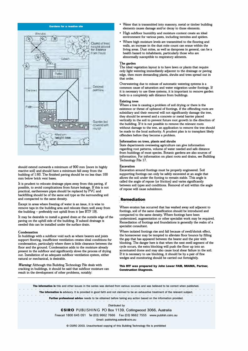
¸±«´¼ »¨¬»²¼ ±«¬©¿®¼ ¿ ³·²·³«³ ±º çðð ³³ ø³±®» ·² ¸·¹¸´§®»¿½¬·ª» ±·´÷ ¿²¼ ¸±«´¼ ¸¿ª» ¿ ³·²·³«³ º¿´´ ¿©¿§ º®±³ ¬¸»¾«·´¼·²¹ ±º ïæêðò ̸» º·²·¸»¼ °¿ª·²¹ ¸±«´¼ ¾» ²± ´» ¬¸¿² ïðð³³ ¾»´±© ¾®·½µ ª»²¬ ¾¿»ò
׬ · °®«¼»²¬ ¬± ®»´±½¿¬» ¼®¿·²¿¹» °·°» ¿©¿§ º®±³ ¬¸· °¿ª·²¹ô ·º°±·¾´»ô ¬± ¿ª±·¼ ½±³°´·½¿¬·±² º®±³ º«¬«®» ´»¿µ¿¹»ò ׺ ¬¸· · ²±¬°®¿½¬·½¿´ô »¿®¬¸»²©¿®» °·°» ¸±«´¼ ¾» ®»°´¿½»¼ ¾§ ÐÊÝ ¿²¼¾¿½µº·´´·²¹ ¸±«´¼ ¾» ±º ¬¸» ¿³» ±·´ ¬§°» ¿ ¬¸» «®®±«²¼·²¹ ±·´¿²¼ ½±³°¿½¬»¼ ¬± ¬¸» ¿³» ¼»²·¬§ò
Û¨½»°¬ ·² ¿®»¿ ©¸»®» º®»»¦·²¹ ±º ©¿¬»® · ¿² ·«»ô ·¬ · ©·» ¬±®»³±ª» ¬¿° ·² ¬¸» ¾«·´¼·²¹ ¿®»¿ ¿²¼ ®»´±½¿¬» ¬¸»³ ©»´´ ¿©¿§ º®±³¬¸» ¾«·´¼·²¹ P °®»º»®¿¾´§ ²±¬ «°¸·´´ º®±³ ·¬ ø»» ÞÌÚ ïç÷ò
׬ ³¿§ ¾» ¼»·®¿¾´» ¬± ·²¬¿´´ ¿ ¹®¿¬»¼ ¼®¿·² ¿¬ ¬¸» ±«¬·¼» »¼¹» ±º ¬¸»°¿ª·²¹ ±² ¬¸» «°¸·´´ ·¼» ±º ¬¸» ¾«·´¼·²¹ò ׺ «¾±·´ ¼®¿·²¿¹» ·²»»¼»¼ ¬¸· ½¿² ¾» ·²¬¿´´»¼ «²¼»® ¬¸» «®º¿½» ¼®¿·²ò
ݱ²¼»²¿¬·±²×² ¾«·´¼·²¹ ©·¬¸ ¿ «¾º´±±® ª±·¼ «½¸ ¿ ©¸»®» ¾»¿®»® ¿²¼ ¶±·¬«°°±®¬ º´±±®·²¹ô ·²«ºº·½·»²¬ ª»²¬·´¿¬·±² ½®»¿¬» ·¼»¿´ ½±²¼·¬·±² º±®½±²¼»²¿¬·±²ô °¿®¬·½«´¿®´§ ©¸»®» ¬¸»®» · ´·¬¬´» ½´»¿®¿²½» ¾»¬©»»² ¬¸»º´±±® ¿²¼ ¬¸» ¹®±«²¼ò ݱ²¼»²¿¬·±² ¿¼¼ ¬± ¬¸» ³±·¬«®» ¿´®»¿¼§°®»»²¬ ·² ¬¸» «¾º´±±® ¿²¼ ·¹²·º·½¿²¬´§ ´±© ¬¸» °®±½» ±º ¼®§·²¹±«¬ò ײ¬¿´´¿¬·±² ±º ¿² ¿¼»¯«¿¬» «¾º´±±® ª»²¬·´¿¬·±² §¬»³ô »·¬¸»®²¿¬«®¿´ ±® ³»½¸¿²·½¿´ô · ¼»·®¿¾´»ò
É¿®²·²¹æ ß´¬¸±«¹¸ ¬¸· Þ«·´¼·²¹ Ì»½¸²±´±¹§ Ú·´» ¼»¿´ ©·¬¸½®¿½µ·²¹ ·² ¾«·´¼·²¹ô ·¬ ¸±«´¼ ¾» ¿·¼ ¬¸¿¬ «¾º´±±® ³±·¬«®» ½¿²®»«´¬ ·² ¬¸» ¼»ª»´±°³»²¬ ±º ±¬¸»® °®±¾´»³ô ²±¬¿¾´§æ
{ É¿¬»® ¬¸¿¬ · ¬®¿²³·¬¬»¼ ·²¬± ³¿±²®§ô ³»¬¿´ ±® ¬·³¾»® ¾«·´¼·²¹»´»³»²¬ ½¿«» ¼¿³¿¹» ¿²¼ñ±® ¼»½¿§ ¬± ¬¸±» »´»³»²¬ò
{ Ø·¹¸ «¾º´±±® ¸«³·¼·¬§ ¿²¼ ³±·¬«®» ½±²¬»²¬ ½®»¿¬» ¿² ·¼»¿´»²ª·®±²³»²¬ º±® ª¿®·±« °»¬ô ·²½´«¼·²¹ ¬»®³·¬» ¿²¼ °·¼»®ò
{ ɸ»®» ¸·¹¸ ³±·¬«®» ´»ª»´ ¿®» ¬®¿²³·¬¬»¼ ¬± ¬¸» º´±±®·²¹ ¿²¼©¿´´ô ¿² ·²½®»¿» ·² ¬¸» ¼«¬ ³·¬» ½±«²¬ ½¿² »²«» ©·¬¸·² ¬¸»´·ª·²¹ ¿®»¿ò Ü«¬ ³·¬»ô ¿ ©»´´ ¿ ¼¿³°²» ·² ¹»²»®¿´ô ½¿² ¾» ¿¸»¿´¬¸ ¸¿¦¿®¼ ¬± ·²¸¿¾·¬¿²¬ô °¿®¬·½«´¿®´§ ¬¸±» ©¸± ¿®»¿¾²±®³¿´´§ «½»°¬·¾´» ¬± ®»°·®¿¬±®§ ¿·´³»²¬ò
̸» ¹¿®¼»²Ì¸» ·¼»¿´ ª»¹»¬¿¬·±² ´¿§±«¬ · ¬± ¸¿ª» ´¿©² ±® °´¿²¬ ¬¸¿¬ ®»¯«·®»±²´§ ´·¹¸¬ ©¿¬»®·²¹ ·³³»¼·¿¬»´§ ¿¼¶¿½»²¬ ¬± ¬¸» ¼®¿·²¿¹» ±® °¿ª·²¹»¼¹»ô ¬¸»² ³±®» ¼»³¿²¼·²¹ °´¿²¬ô ¸®«¾ ¿²¼ ¬®»» °®»¿¼ ±«¬ ·²¬¸¿¬ ±®¼»®ò
Ѫ»®©¿¬»®·²¹ ¼«» ¬± ³·«» ±º ¿«¬±³¿¬·½ ©¿¬»®·²¹ §¬»³ · ¿½±³³±² ½¿«» ±º ¿¬«®¿¬·±² ¿²¼ ©¿¬»® ³·¹®¿¬·±² «²¼»® º±±¬·²¹ò ׺·¬ · ²»½»¿®§ ¬± «» ¬¸»» §¬»³ô ·¬ · ·³°±®¬¿²¬ ¬± ®»³±ª» ¹¿®¼»²¾»¼ ¬± ¿ ½±³°´»¬»´§ ¿º» ¼·¬¿²½» º®±³ ¾«·´¼·²¹ò
Û¨·¬·²¹ ¬®»»É¸»®» ¿ ¬®»» · ½¿«·²¹ ¿ °®±¾´»³ ±º ±·´ ¼®§·²¹ ±® ¬¸»®» · ¬¸»»¨·¬»²½» ±® ¬¸®»¿¬ ±º «°¸»¿ª¿´ ±º º±±¬·²¹ô ·º ¬¸» ±ºº»²¼·²¹ ®±±¬ ¿®»«¾·¼·¿®§ ¿²¼ ¬¸»·® ®»³±ª¿´ ©·´´ ²±¬ ·¹²·º·½¿²¬´§ ¼¿³¿¹» ¬¸» ¬®»»ô¬¸»§ ¸±«´¼ ¾» »ª»®»¼ ¿²¼ ¿ ½±²½®»¬» ±® ³»¬¿´ ¾¿®®·»® °´¿½»¼ª»®¬·½¿´´§ ·² ¬¸» ±·´ ¬± °®»ª»²¬ º«¬«®» ®±±¬ ¹®±©¬¸ ·² ¬¸» ¼·®»½¬·±² ±º¬¸» ¾«·´¼·²¹ò ׺ ·¬ · ²±¬ °±·¾´» ¬± ®»³±ª» ¬¸» ®»´»ª¿²¬ ®±±¬©·¬¸±«¬ ¼¿³¿¹» ¬± ¬¸» ¬®»»ô ¿² ¿°°´·½¿¬·±² ¬± ®»³±ª» ¬¸» ¬®»» ¸±«´¼¾» ³¿¼» ¬± ¬¸» ´±½¿´ ¿«¬¸±®·¬§ò ß °®«¼»²¬ °´¿² · ¬± ¬®¿²°´¿²¬ ´·µ»´§±ºº»²¼»® ¾»º±®» ¬¸»§ ¾»½±³» ¿ °®±¾´»³ò
ײº±®³¿¬·±² ±² ¬®»»ô °´¿²¬ ¿²¼ ¸®«¾Í¬¿¬» ¼»°¿®¬³»²¬ ±ª»®»»·²¹ ¿¹®·½«´¬«®» ½¿² ¹·ª» ·²º±®³¿¬·±²®»¹¿®¼·²¹ ®±±¬ °¿¬¬»®²ô ª±´«³» ±º ©¿¬»® ²»»¼»¼ ¿²¼ ¿º» ¼·¬¿²½»º®±³ ¾«·´¼·²¹ ±º ³±¬ °»½·»ò Þ±¬¿²·½ ¹¿®¼»² ¿®» ¿´± ±«®½» ±º·²º±®³¿¬·±²ò Ú±® ·²º±®³¿¬·±² ±² °´¿²¬ ®±±¬ ¿²¼ ¼®¿·²ô »» Þ«·´¼·²¹Ì»½¸²±´±¹§ Ú·´» ïéò
Û¨½¿ª¿¬·±²Û¨½¿ª¿¬·±² ¿®±«²¼ º±±¬·²¹ ³«¬ ¾» °®±°»®´§ »²¹·²»»®»¼ò ͱ·´«°°±®¬·²¹ º±±¬·²¹ ½¿² ±²´§ ¾» ¿º»´§ »¨½¿ª¿¬»¼ ¿¬ ¿² ¿²¹´» ¬¸¿¬¿´´±© ¬¸» ±·´ «²¼»® ¬¸» º±±¬·²¹ ¬± ®»³¿·² ¬¿¾´»ò ̸· ¿²¹´» ·½¿´´»¼ ¬¸» ¿²¹´» ±º ®»°±» ø±® º®·½¬·±²÷ ¿²¼ ª¿®·» ·¹²·º·½¿²¬´§¾»¬©»»² ±·´ ¬§°» ¿²¼ ½±²¼·¬·±²ò λ³±ª¿´ ±º ±·´ ©·¬¸·² ¬¸» ¿²¹´»±º ®»°±» ©·´´ ½¿«» «¾·¼»²½»ò
λ³»¼·¿¬·±²
ɸ»®» »®±·±² ¸¿ ±½½«®®»¼ ¬¸¿¬ ¸¿ ©¿¸»¼ ¿©¿§ ±·´ ¿¼¶¿½»²¬ ¬±º±±¬·²¹ô ±·´ ±º ¬¸» ¿³» ½´¿·º·½¿¬·±² ¸±«´¼ ¾» ·²¬®±¼«½»¼ ¿²¼½±³°¿½¬»¼ ¬± ¬¸» ¿³» ¼»²·¬§ò ɸ»®» º±±¬·²¹ ¸¿ª» ¾»»²«²¼»®³·²»¼ô ¿«¹³»²¬¿¬·±² ±® ±¬¸»® °»½·¿´·¬ ©±®µ ³¿§ ¾» ®»¯«·®»¼òλ³»¼·¿¬·±² ±º º±±¬·²¹ ¿²¼ º±«²¼¿¬·±² · ¹»²»®¿´´§ ¬¸» ®»¿´³ ±º ¿°»½·¿´·¬ ½±²«´¬¿²¬ò
ɸ»®» ·±´¿¬»¼ º±±¬·²¹ ®·» ¿²¼ º¿´´ ¾»½¿«» ±º ©»´´ñ¸®·²µ »ºº»½¬ô¬¸» ¸±³»±©²»® ³¿§ ¾» ¬»³°¬»¼ ¬± ¿´´»ª·¿¬» º´±±® ¾±«²½» ¾§ º·´´·²¹¬¸» ¹¿° ¬¸¿¬ ¸¿ ¿°°»¿®»¼ ¾»¬©»»² ¬¸» ¾»¿®»® ¿²¼ ¬¸» °·»® ©·¬¸¾´±½µ·²¹ò ̸» ¼¿²¹»® ¸»®» · ¬¸¿¬ ©¸»² ¬¸» ²»¨¬ ©»´´ »¹³»²¬ ±º ¬¸»½§½´» ±½½«®ô ¬¸» »¨¬®¿ ¾´±½µ·²¹ ©·´´ °«¸ ¬¸» º´±±® «° ·²¬± ¿²¿½½»²¬«¿¬»¼ ¼±³» ¿²¼ ³¿§ ¿´± ½¿«» ´±½¿´ ¸»¿® º¿·´«®» ·² ¬¸» ±·´ò׺ ·¬ · ²»½»¿®§ ¬± «» ¾´±½µ·²¹ô ·¬ ¸±«´¼ ¾» ¾§ ¿ °¿·® ±º º·²»©»¼¹» ¿²¼ ³±²·¬±®·²¹ ¸±«´¼ ¾» ½¿®®·»¼ ±«¬ º±®¬²·¹¸¬´§ò
̸· ÞÌÚ ©¿ °®»°¿®»¼ ¾§ Ö±¸² Ô»©»® Úß×Þô Ó×ßÓßô ﮬ²»®ô
ݱ²¬®«½¬·±² Ü·¿¹²±·ò
̸» ·²º±®³¿¬·±² ·² ¬¸· ¿²¼ ±¬¸»® ·«» ·² ¬¸» »®·» ©¿ ¼»®·ª»¼ º®±³ ª¿®·±« ±«®½» ¿²¼ ©¿ ¾»´·»ª»¼ ¬± ¾» ½±®®»½¬ ©¸»² °«¾´·¸»¼ò
̸» ·²º±®³¿¬·±² · ¿¼ª·±®§ò ׬ · °®±ª·¼»¼ ·² ¹±±¼ º¿·¬¸ ¿²¼ ²±¬ ½´¿·³»¼ ¬± ¾» ¿² »¨¸¿«¬·ª» ¬®»¿¬³»²¬ ±º ¬¸» ®»´»ª¿²¬ «¾¶»½¬ò
Ú«®¬¸»® °®±º»·±²¿´ ¿¼ª·½» ²»»¼ ¬± ¾» ±¾¬¿·²»¼ ¾»º±®» ¬¿µ·²¹ ¿²§ ¿½¬·±² ¾¿»¼ ±² ¬¸» ·²º±®³¿¬·±² °®±ª·¼»¼ò
Ü·¬®·¾«¬»¼ ¾§
ÝÍ×ÎÑ ÐËÞÔ ×ÍØ ×ÒÙ ÐÑ Þ±¨ ïïíçô ݱ´´·²¹©±±¼ íðêêô ß«¬®¿´·¿
Ú®»»½¿´´ ïèðð êìë ðëï Ì»´ øðí÷ çêêî éêêê Ú¿¨ øðí÷ çêêî éëëë ©©©ò°«¾´·¸ò½·®±ò¿«
Û³¿·´æ °«¾´·¸·²¹ò¿´»à½·®±ò¿«
w ÝÍ×ÎÑ îððíò ˲¿«¬¸±®·»¼ ½±°§·²¹ ±º ¬¸· Þ«·´¼·²¹ Ì»½¸²±´±¹§ º·´» · °®±¸·¾·¬»¼
Ù¿®¼»² º±® ¿ ®»¿½¬·ª» ·¬»