Embed Size (px)
Citation preview
Southern African Large Telescope
Prime Focus Imaging Spectrograph
Spare Electronics Acceptance Testing Report
Jeffrey W PercivalKen Nordsieck
University of Wisconsin
Document Number: SALT-3160AR0006
Revision 1.012 September 2007
1. Introduction
This document describes the results of the acceptance testing of the RSS Spare Electronicsboxes, fabricated in Madison, Wisconsin. The spare set of boxes was built between 2005 &2007, after RSS had been shipped to Sutherland and during the acceptance testing phase of RSSon the telescope.
The acceptance testing of the spare electronics was complicated by not having the RSSinstrument in Madison. To mitigate this issue, we designed and built “mechanism simulators”,small boxes with the same connector interface as the real mechanisms on the RSS. Each box hadtoggle switches to simulate discrete inputs such as forward and reverse hard limits of travel,station indicators, inserted and removed conditions, and so on. Some also had temperaturesensors or potentiometers for the analog input channels.
We procured motors and encoders as needed for each mechanism simulator. The simulator boxeshave all the connectors needed to allow LabVIEW to drive the motors, in closed loop if required.
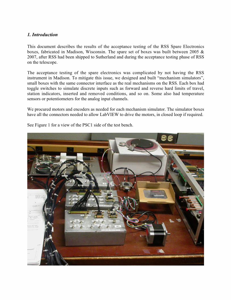
See Figure 1 for a view of the PSC1 side of the test bench.
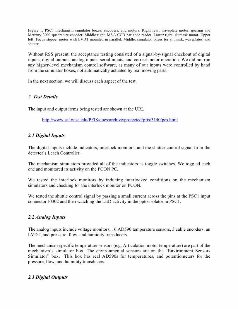
Figure 1: PSC1 mechanism simulator boxes, encoders, and motors. Right rear: waveplate motor, gearing andMercury 3000 quadrature encoder. Middle right: MS-3 CCD bar code reader. Lower right: slitmask motor. Upperleft: Focus stepper motor with LVDT mounted in parallel. Middle: simulator boxes for slitmask, waveplates, andshutter.
Without RSS present, the acceptance testing consisted of a signal-by-signal checkout of digitalinputs, digital outputs, analog inputs, serial inputs, and correct motor operation. We did not runany higher-level mechanism control software, as many of our inputs were controlled by handfrom the simulator boxes, not automatically actuated by real moving parts.
In the next section, we will discuss each aspect of the test.
2. Test Details
The input and output items being tested are shown at the URL
http://www.sal.wisc.edu/PFIS/docs/archive/protected/pfis/3140/pcs.html
2.1 Digital Inputs
The digital inputs include indicators, interlock monitors, and the shutter control signal from thedetector’s Leach Controller.
The mechanism simulators provided all of the indicators as toggle switches. We toggled eachone and monitored its activity on the PCON PC.
We tested the interlock monitors by inducing interlocked conditions on the mechanismsimulators and checking for the interlock monitor on PCON.
We tested the shuttle control signal by passing a small current across the pins at the PSC1 inputconnector J0302 and then watching the LED activity in the opto-isolator in PSC1.
2.2 Analog Inputs
The analog inputs include voltage monitors, 16 AD590 temperature sensors, 3 cable encoders, anLVDT, and pressure, flow, and humidity transducers.
The mechanism-specific temperature sensors (e.g. Articulation motor temperature) are part of themechanism’s simulator box. The environmental sensors are on the “Environment SensorsSimulator” box. This box has real AD590s for temperatures, and potentiometers for thepressure, flow, and humidity transducers.
2.3 Digital Outputs

The digital outputs include solid state switches for various voltages, pneumatic valve controls,solenoid activation, and heater circuits.
We checked the solid state switches for Motor +24V, Pneumatic +24V, and Star Tracker +24Vusing the voltage monitor values read back from the hardware.
We checked the Etalon AC control with a voltage meter plugged into the AC sockets on thePDS.
We checked the pneumatic control by watching the LEDs on the Festo valves.
We checked the shutter open command with the Shutter Coil Energized LED on the shuttersimulator box.
We checked the articulation brake control with the Brake Energized LED on the articulationsimulator box.
We checked the heater control with a voltage meter on the proper D-connector pins.
2.4 Motor Control
We verified the motor control using National Instrument’s Measurement and AutomationExplorer (MAX). We configured each PXI-7734 axis using MAX, and then used the “1-DInteractive” panels to run the motor. We confirmed that each motor moved in a positive direction(clockwise when looking down the shaft towards the motor) when given a position step countfrom MAX, and that each encoder (waveplate, grating rotation, and articulation) matched apositive move with a positive count. See the Notes section below for more on encoders.
2.5 Serial I/O
There are 4 channels of serial I/O: 2 bar code readers, and 2 etalon controllers. We checked the 4channels by successively writing to and reading from the bar code reader. We commanded andreceived valid bar codes through each of the channels.
3. Notes
3.1 Motor and Encoder Phasing
National Instruments adopts the following conventions with stepper motors: a positive step countmoves the motor shaft clockwise as you look down the shaft towards the motor body, and inclosed loops, a positive motor motion must produce an increasing step count. This means that the
motor phasing, whether it is forward/reverse or step/direction, and the quadrature encoderphasing (A+,A- and B+,B-) must be such that these conventions are followed. All of themotorized axes in the RSS Spare PSC1 & PSC2 have been verified to follow the clockwise shaftconvention. There are three areas to be aware of.
3.1.1 Waveplates
Our waveplate motor/encoder mockup (upper right in Figure 1) has the motor mounted “upsidedown” compared to the actual RSS waveplate motors. Because this inverts the gearing, thewaveplate (in our mockup) goes the wrong way. We compensated for this by inverting thequadrature phasing (swap A+ with B+, swap A- with B-). We did this in the simulator wiring, inthe cable between the Mercury 3000 chrome signal conditioner (with the 4 green LEDs) and theD-connector on the waveplate simulator box. We tagged this cable with a tape label saying“SWP”. The spare PSC1 is wired correctly for the real waveplates.
3.1.2 Grating Rotation
The grating rotation encoder is mounted on the rear shaft of a double-shafted stepper, so its“natural” counting direction is backwards from what the motion controller expects. In our sparesacceptance testing, we fixed this by swapping phases (as with the waveplates) in a test cable, notin the PSC2 box. We swapped the phases at the E5D encoder, at the 10-pin connector that plugsinto the encoder body. We tagged this cable with a tape label saying “SWP”.
The original PSC2 has the swap inside the PSC2 box. We failed to document where we made theswap: at the UMI-7764? At a front-panel D-connector? We failed to document this deviationfrom the schematics (or to update the schematics), and no one can recall where this change wasmade. Brennan verified that the swap does actually take place in PSC2, but he did not pin downits location.
We’ve decided to defer this change to the engineers at SALT, so that the two PSC2s can be madeto match. The Spare PSC2 is not phased correctly for the grating rotation encoder.
3.1.3 Articulation
We didn’t buy a Heidenhain Tape Encoder for the articulation because we didn’t have a way tomount and test it. To close the articulation loop, we made a cable that mated with the gratingrotation motor’s E5D encoder cable, connected to the articulation simulator’s encoder inputconnector, and verified that it counted up when we spun the motor in a positive (CW) direction.This showed that there were no phasing errors inside PSC2 for the articulation wiring.
4. Deliverables
The RSS Spares Project includes these deliverable and donated items:
• Box 1: Power Distribution System (PDS)• Box 2: Signal Conditioning Box (SCB)• Box 3: PFIS Satellite Controller 1 (PSC1)• Box 4: PFIS Satellite Controller 2 (PSC2)
4.1 Testing and Diagnostics
In addition, we include these items built for testing and diagnostics:
• Inter-box cabling (1 set, no sleeves or shields)• Mechanism simulators
4.2 Motors and Encoders
In addition, we include these items used to support testing, and which stand as spares for devicesin the instrument:
• Motors:o Slitmask – 1 Oriental Motors PK266-02A Steppero Waveplate – 1 Oriental Motors PMC35A3 Steppero Shutter – N/Ao Focus – 1 Physik Instrumente M-230.10S Stepper Micrometero Etalons – N/Ao Grating Magazine– 1 Oriental Motors PK545AMA Steppero Grating Rotation – 1 Nanotec 4H4009-L-3Bo Beamsplitter – N/Ao Filter – 1 Oriental Motors PK266-2A Steppero Articulation – 1 Slo-Syn KML063F13E Stepper
• Encoders:o Slitmask – 2 Unimeasure LX-PA-15-10K Cable Position Transducers, spares for
slitmask, grating, filtero Waveplate – 1 MicroE Systems Mercury 3000 Quadrature Encodero Shutter – N/Ao Focus – Schaevitz 100DCSE0006 LVDTo Etalons – N/Ao Grating Magazine – See slitmask note aboveo Grating Rotation – 3 US Digital E5D Optical Quadrature Encoderso Beamsplitter – N/Ao Filter – See slitmask note above
o Articulation – Not Provided
4.3 Ancillary Spare Equipment:
• National Instruments documents and CDs• 1 PXI 1000B Chassis• 1 PXI-7334 Motion Control Card• 1 UMI-7764 Motion Interface• 1 1-meter PXI-6071E to SCB-100 cable• 1 TSI Model 41211 Flow Sensor• 2 HM1500LF Relative Humidity Sensors• 1 Microscan MS-3 CCD Bar Code Scanner• 1 SI-Tech Fiber Audio Receiver
4.4 Miscellaneous parts
• Festo pneumatic tubing• 1 Festo valve• 12 Festo Proximity Sensors SMEO-4-K-LED-24-B• 17 Festo Proximity Sensors SME-8-K-LED-24• 1 Festo Valve Cable• Misc. Festo parts and pieces• 1 IM481H Motor Control Chip (used in the INT-481 board for grating rotation)