Embed Size (px)
Citation preview

1988-09 Spring 1988
Facility Design and Efficiency SOUTHERN METHODIST UNIVJ Scheduling of Job Shop
Operation
Jim Koch
Development
DEPARTMENT OF OPERATIONS RESEARCH AND ENGINEERING MANAGEMENT
SCHOOL OF ENGINEERING AND APPLIED SCIENCE
DALLAS, TEXAS 75275

Table of Contents
Abstract ii
Background 1
Subject ......................... i Purpose ......................... 1
Scope .......................... 2
Method .......................... 2
Plan of Development ................... 2
Results ......................... 3
Facility Layout ..................... 3 Equipment Requirements .............. 3 Layout Option 1 .................. 4 Layout Option 2 .................. 5 Layout Option 3 .................. 6
Automation Proposal ................... 7
Productivity ....................... 8
Weekly Labor Cost Breakdown ............... 10
1

Abstract
This project considers the existing facility layout at
I I II I I I I I I I I. I I' I I
Landell Manufacturing, Inc. based in Houston, Texas. Landell
provides a large array of specialty pipe flange fittings.
The problems foreseen and examined extensively in this study
include facility design layout, material handling, size of
the required workforce, and the possibility of adding
inventory stock. At this time, Landell Manufacturing is
designed with a process layout, requiring six machinists at
full capacity and excess material handling. Also, Landell
currently operates under "just-in-time" manufacturing and the
possibility of adding an inventory stock will be considered.
ii

L Background
Landell Manufacturing was formed in 1979 amid the Texas oil
boom of the late 1970s and early 1980s. Landell was created
as a manufacturer and supplier of pipe flanging directly
related to the oil business. Due to the recession of the oil
industry in the mid-1980s, Landell was forced to cut its
plant size and workforce in order to adapt to the changing
industry demands. Today, Landell is a leading supplier of
specialty pipe flanging catering to a wide range of
industries in the Houston area.
Subiect
The subject of this report is facility layout, material
handling, and inventory stock of a job shop operation and
their importance in engineering an efficient manufacturing
operation. The plant under study is currently operating with
a process layout design along with just-in-time
manufacturing.
Purpose
The purpose of this report is to determine the most efficient
and safe facility design for Landell Manufacturing by
studying many alternative design options including possible
automated material handling devices. In addition, this
I I I I I I I I I I I I I II 1
I I

Facility Design and Efficiency Scheduling of a Job Shop Operation
Prepared for Landell Manufacturing, Inc.
1200 Townhurst Road Houston, Texas 77055
by
Jim Koch
May 8, 1988

I I
report will study the possibility of implementing an
inventory stock, opposed to operating under just-in-time
manufacturing.
Scope
The material for this report was gathered from on-site
studies and personal interviews with Darrel Godard, Plant
Manager at Landell. Other general information was gained
through my studies in Engineering Management at Southern
Methodist University.
Method
For the most part, the information was obtained through
personal interviews with Landell employees and on-site
studies. In obtaining the data concerning the facility
layout and floor space requirements for various equipment,
blueprints and machinery catalogs were referenced.
Information concerning the Ergolift material handling devices
was obtained from Koch Machinery, Inc., a machine tool
distributorship in Houston.
Plan of Development
This report first examines the equipment necessary in the
production of pipe flanging as well as the current layout
design of Landell. Other layout options will be examined
2
I I I I I I I I I I I I I I I I I I

with their required maximum workforce. Next material
handling automation will be studied followed by a proposed
change in inventory stock. Finally, the results and final
proposal will be made at the conclusion of this report.
Results
The results from the implementation of the facility layout
techniques, used as a tool towards increased efficiency, is
apparent through model design analysis. The benefits of
proposed changes in facility design, material handling, and
inventory stock will be stated at the end of this report as
well as a breakdown of the cost variances.
Facility Layout
Equipment Requirements
The manufacturing of pipe flanging is a two-step process
requiring the use of only two machines, a lathe and a drill
press. Landell is currently operating with six machines,
three machining lathes and three drill presses of comparable
sizes. The lathes are various Monarch Lathes made in Sidney,
Ohio, and the drill presses are Babin Circi-matics made in
Beaumont, Texas.
The three Monarch lathes are different sizes designed to
handle various forging sizes. The Monarch TC-2 can handle
3

raw forging from 0-12 inches in diameter. The Monarch TC-3
carries raw forging up to 15 inches in diameter and the TC-4
can handle up to 18 inches in diameter. The actual flange
job is assigned to the smallest lathe available that can
handle the required diameter.
The three drill presses are of comparable sizes to the three
matching lathes. The Babin Model 12 can work flanging from
0-12 inches in diameter. The Model 24 and Model 24E can
handle diameters of 16 inches and 20 inches respectively.
The flow of the production is such that any part machined on
the smallest of the three lathes can be drilled by any of
three drills. This flow can be seen in Figure 1 at the back
of the report. However, in order to achieve maximum
productivity without unnecessarily tying up a large machine
than required, the optimal job flow is to the drill press of
corresponding size.
I I
Layout Option 1
The first option for the facility layout is the existing
design. Namely, the first option is to not change anything.
Landell is currently operating with a process layout. With
this there is a functional division in which general purpose
I
machines are used for a variety of product sizes. In other
words, the equipment is grouped by the type of the process.
I 4
I I I I I I I I I I I
I

The lathes are all stationed together as are the drill
presses. With this layout, the products are routed through
the functional departments in the required order. This
design can be seen in the back as Layout Option 1.
With this type of process layout, six machinists are required
to run the plant at maximum capacity. One machinist would be
stationed at each of the six machines. One of the major
problems with this layout is the lathe operators are cramped
together and they complain that they don't have enough room
to work efficiently. Another problem with this layout is
that it leads to congested material handling. The forklift
operator is constantly moving materials from one end of the
warehouse to the other.
Layout Option 2
The second option for the facility layout can be seen in the
back, Layout Option 2. This second option is a process
layout like the existing design, only the three lathes are
reattached to create a more open atmosphere. 5his more open structure allows the workers to see everything else that's
going on. Also, the lathe operators have more room to work
with than they did the existing layout.
I I 5
LI I I I I I I I I I I I I I I
11
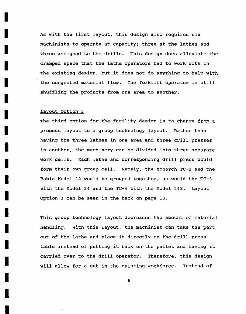
As with the first layout, this design also requires six
machinists to operate at capacity; three at the lathes and
three assigned to the drills. This design does alleviate the
cramped space that the lathe operators had to work with in
the existing design, but it does not do anything to help with
the congested material flow. The forklift operator is still
shuffling the products from one area to another.
Layout Option 3
The third option for the facility design is to change from a
process layout to a group technology layout. Rather than
having the three lathes in one area and three drill presses
in another, the machinery can be divided into three separate
work cells. Each lathe and corresponding drill press would
form their own group cell. Namely, the Monarch TC-2 and the
Babin Model 12 would be grouped together, as would the TC-3
with the Model 24 and the TC-4 with the Model 24E. Layout
Option 3 can be seen in the back on page 13.
This group technology layout decreases the amount of material
handling. With this layout, the machinist can take the part
out of the lathe and place it directly on the drill press
table instead of putting it back on the pallet and having it
carried over to the drill operator. Therefore, this design
will allow for a cut in the existing workforce. Instead of
I
6
I

having six machinist at full capacity, three can do
approximately the same amount of work. Rather than having
one machinist assigned to each of the six machines, assign
one worker to each of the three machining cells. While a
part is being run on the lathe, the operator can be running
another part on the drill press.
Automation Proposal
With the third layout option, the material handling is
decreased within the plant, but increased for the three work-
cell operators. Instead of moving each forge twice as in the
existing design, the operator moves each forge three times;
from the pallet to the lathe, from the lathe to the drill,
and from the drill back to the pallet. Therefore, there is
more work expected from the three operators than before.
The addition of an automated material handling device, namely
an Ergolift, would alleviate this excess work. The Ergolift
is a manually controlled hydraulic lifting arm operated by
means of a handle on the tool attachment. With the lift, a
load can easily be moved manually at any time in all
directions. When the control handle is in the neutral
position, the load will always be maintained at a constant
level. No resetting is necessary when the load is changed.
This type of hydraulic lift provides:
I VA
I I E I I I I I I I I I I I I I
I

1. Increased production and profit by shortening the
handling and manufacturing times
2. Higher productivity and profit by reducing the
manpower requirements
3. Improved working environment by eliminating strenuous
manual operations and ensuring safe and convenient
handling
4. Higher quality by reducing the incidence of handling
I damage.
Productivity
Under the current condition, all six machinists together
produce a maximum of 48 flanges per hour, or 384 flanges per
day. With the proposed change to a work cell layout, each of
the three machinists can produce only 15 flanges per hour or
360 flanges per day. However, with the work cell layout and
the added automation device in the two larger group cells,
productivity will increase by 2-3 flanges per hour. This
would bring the total to about 400 flanges a day.
Proposal
After studying the situation at Landell and examining various
alternatives, I would like to make two proposals for Landell.
First, change from a process layout as in Option 1 to a group
technology layout as in Option 3. Second, add the automated
I 8
I I I I El I
I I I I I I I I I
I

I I material handling devices in the two larger work cells. The
I parts in the smallest cell are small enough that the Ergolift would not benefit as it would in the larger two cells.
IThe benefits from these two proposals would be improved
material handling, easier product flow, a cutback of 50% in
theworkforce, and improved productivity. The cost breakdown
can be seen on the next page.
I I I I I I I I I I I 9
I
I I I I I I I I I I I I I I I I I I I
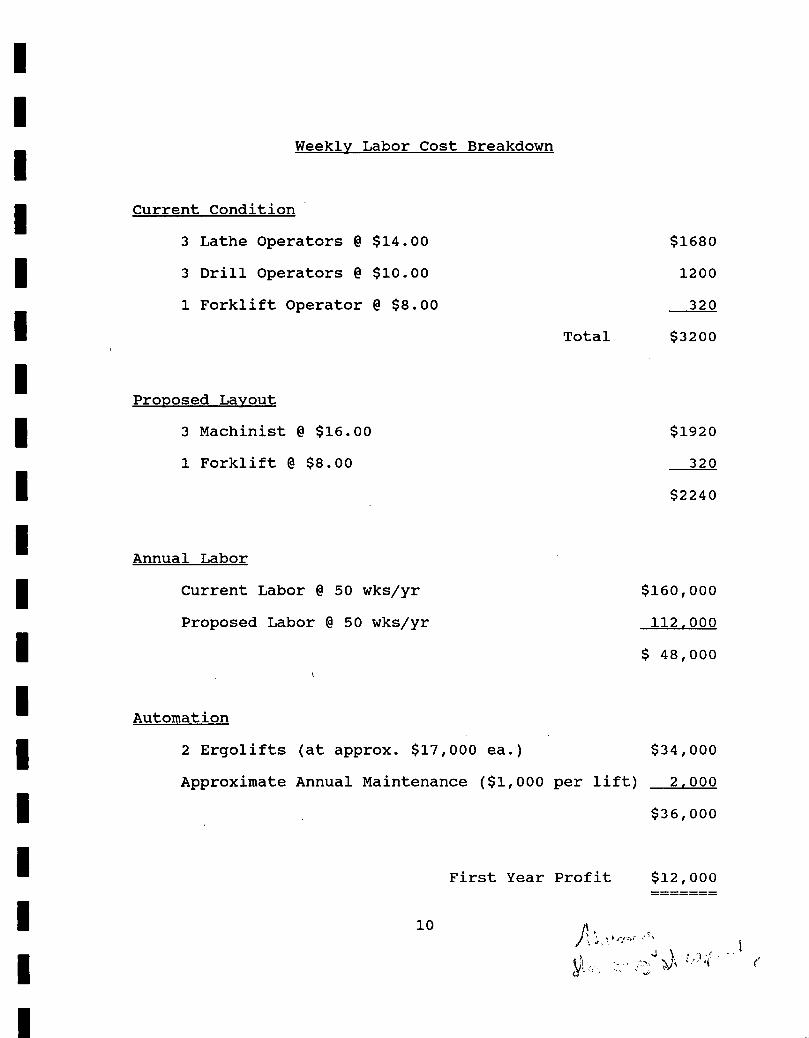
Weekly Labor Cost Breakdown
Current Condition
3 Lathe Operators @ $14.00
$1680
3 Drill Operators @ $10.00
1200
1 Forklift Operator @ $8.00
320
Total
$3200
Proposed Layout
3 Machinist @ $16.00
$1920
1 Forklift @ $8.00
320
$2240
Annual Labor
Current Labor @ 50 wks/yr
$160,000
Proposed Labor @ 50 wks/yr 112,000
$ 48,000
Automation
2 Ergolifts (at approx. $17,000 ea.) $34,000
Approximate Annual Maintenance ($1,000 per lift) 2,000
$36,000
First Year Profit $12,000
10A
1

I tEsLL J
br.II J
I ____L'I
I,
II
I-- - - - - -
MOAJAW4
L A flL F •n
LAT
TC-3
Tc2.
O14,E5
YOUT OPTION 1
- 11

I kILL I
-I
NaL
Al
1----__
11jJ6
Mo )/M1
Tc-3 . AT(46
LATHE
T00'oFFiE$
LAYOUT OPTION 2
A
12

I I
•1 I I I I I I I I I I I I I I I I
13
LA'n4E
1-3
LAYOUT OPTION 3
;0 iPt'
1,L7c-
LAtI4E

RAW - METAL FoR&/J,-
PtNtEI ?oc.T- ?' PE RAu&
14
I I I I I I I I I I I I I I I I I I I
[I] MI.!

[0I0Ii.I.t1I (I. I!J 1JiiTJ,1
Figure 16-1. Approximate floor space for Monarcri TC2 and TC3.
FIgure 16-2. Approximate
I - -I - . -- ---_
• 1 _____
__I !
•' r __
LII:::
[I
— V.. -? • •—' -________ ..& -.-.. ..
.. — — - .
- - .
I I__h• _-Q - - - - -
U15
MoMAcH LATH S
Mo EL FLo*. PAE • R'D
TC-2.-
Tc.-3 16' c ft 5'
TC.-4
Obt. /%jAx tm. O
rc-3

TO Ii
In
h
L T fl 1
EA
0 _
I. 0-
RiLL- 1L'OR.'S PACE RE.&b MAX Z,A. or-
MaDEL (2 o
*EL •7M
6s' x4' r(obeL. 2.'IE
16

I I I I I I I I I I I I I I I I I I I
IJ
Lr ____:. ------------------)
I KATE,
17

C)LIFT 8
EFFICIENT
VERSATILE SAFE
El
fN) T
-C AT
1!

Arm system Drive unit
Alpha axis
Control handle
Z-axis
XaxS
axis
Tool attachment
Powered travel, steplessly adjustable.
• Manual travel
The design of the ERGOLIFT is shown in the above figure. The lifting arm is usually supported by a floor-mounted pillar and can be rotated manually through 3600 around the pillar. (Horizontal rotating is the theta axis.)
The CONTROL HANDLE and the TOOL ATTACHMENT are integrated into a single unit which is manually movable along the X axis (horizontally) and is hydraulically movable along the Z axis (vertically). This unit can also be rotated manually through 3600 about its own center axis. (Horizontal rotation is the alpha axis.)
The DRIVE UNIT consists of a quiet hydraulic system powered by a three-phase electric motor. In the event of failure of the power supply, hose failure, etc., a special valve will immediately lock the load in position.
The ARM SYSTEM utilizes a low-friction linkage with a tie rod designed to hold the tool attachment horizontal at all times, regard-less of the position of the arm.
The control handle is simple and logical to use. Turn the handle up to lift and down to lower the load. The more the control lever is displaced from the neut-ral position, the faster the arm will move. The handle is of ergonomic design and provides perfect control of all movements of the lifting arm.
ERGOLIFT A large proportion of the activities in industry
and commerce consists of moving material from one place to another. By force of habit, we often do this by hand or we use Inappropriate equipment for assisting us in the task.
The usual jib crane with an electric chain hoist is often too slow and inconvenient. It cannot balance and hold the load In predetermined positions while lifting. And it cannot always meet the precision requirements.
The Industrial robot or automatic manipulator is often far too expensive. The total investment cost of an installation of this type usually amounts to twice the basic price of the robot.
On the other hand, the ERGOLIFT opens up many new opportunities for fast, convenient and safe handling of moderate loads. It relieves the operator of strenuous operations, such as grip-ping, lifting, holding and turning an object, and it does this quickly and with high precision.
Handling that normally requires at least two men can be managed by one man using the ERGOLIFT - quickly, safely and without manual strain.
When fitted with suitable lifting tools, the ERGOLIFT is a versatile and economical aid that provides the perfect solution to many handling problems.
ERGOLIFT PROVIDES • Increased production and profit by shorten-
ing the handling and manufacturing times. • Higher productivity and profit by reducing
the manpower requirements. • Improved working environment by eliminat-
Ing strenuous manual operations and ensuring safe and convenient handling.
• Higher quality by reducing the incidence of handling damage.
ERGOLIFT IS • Easy to operate, with simple and logical
controls. • Convenient to operate, with fingertip con-
trol of all movements and an ergonomically designed control handle.
• Safe to operate, since It incorporates safety functions.
• Reliable and easy to maintain, due to its simple design and high quality.
OPERA liON The ERGOLIFT is a manually controlled hydraulic lifting
arm operated by means of a handle on the tool attachment. The control handle can be used to regulate the lifting speed steplessly from rest up to the maximum speed. The handle is spring-loaded and returns to the neutral position when released. The load will then stop immediately and will be automatically balanced. No resetting is necessary when the load is changed.
The load can easily be moved manually at any time in all horizontal directions. When the control handle is in the neut-ral position, the load will always be maintained at a constant level. The vertical and horizontal movements can be coordi-nated, so that the load will always be moved in the required direction.

ROTATION LATCH All manually rotatable grippers can
be ordered with a rotation latch to lock the rotation about the gamma axis to certain predetermined positions.
Stationary installation on a floor-mounted pillar.
Stationary installation on an overhead pillar. Stationary installation on a wall bracket.
LIFTING AND HANDLING TOOLS
The gripping units outlined here have proven to be the solution to many of the handling problems encountered by our customers.
i L'-Alpha axis r included in the lifting arm
Gamma axis -
I /
/>ttIlIIIø
/ Beta axis .
- - - - -
Adjustable positions Manual or powered travel.
The ERGOGRIP is a hydraulic, modular gripping unit for objects weigh-ing up to about 440 lbs. The design of the unit is shown in the adjacent figure.
The tool, which is available in eleven basic versions (see below), is con-nected to the hydraulic system of the ERGOLIFT and requires no additional hydraulic power supply. The gripping jaws are easily replaceable and are matched to suit the object to be handled.
Some important benefits WIDE GRIPPING RANGE
U HIGH GRIPPING FORCE • COMPACT DIMENSIONS AND LOW
DEADWEIGHT • MODULAR DESIGN • EXTERNAL AND INTERNAL GRIP-
PING FUNCTION (optional) El HIGH SAFETY For further information, please send for a special leaflet.
EGH10 Horizontal installation With clamp mounting, for stepless adjustment about the gamma axis.
EGH20/EGH25 Vertical sloping installation. The slope angle is adj ustable in steps to 0, 15, 30 and 400 about the beta axis. EGH20. With clamp mounting, for stepless adjust-ment about the gamma axis. EGH25. Manually rotatable through about 340° about the gamma axis.
CONTROL OF THE ERGOGRIP
Accessories
The gripping unit can be controlled by means of levers or push-buttons. The lever UNLIMITED ROTATION control unit is more common and is a rugged and inexpensive alternative, but Gripping units with manual rotation requires more space than the push-button unit. The push-button unit can be used about the gamma axis can be ordered with one hand for controlling the lifting arm and gripping unit, with unlimited angle of rotation about
this axis.
Type VU-H lever control unit
Type VU-S push-button control unit
EGH30/EGH60 EGH25/EGH65 with rotation latch with rotation latch
STATIONARY AND MOBILE INSTALLATION The most common methods of installation are illustrated below.
The ERGOLIFT can be equipped with a wide variety of tools. The actual design of the tool is dependent upon the specific application. Typical tools Include lifting hooks, lifting tongs, magnetic and suction tools, and hydraulic grippers.
In many cases, we manufacture special tools to meet the customer's requirements.
THE ERGOGRIP GRIPPING UNIT
EGH22 Vertical installation. With clamp mount- EGH30 Horizontal installation. Manually rotat-ing, for stepless adjustment about the gamma axis. able through about 3400 about the gamma axis.
EGII40 Horizontal installation. Powered rotary motion about the gamma axis. Angular rotation through 900 1800,2700 and 360°.
EGHSO EGH60 Powered tilting motion of 90 about the beta axis. The gamma axis is located off-center. EGHSO. With damp mounting, for stepless adjust-ment about the gamma axis. EGH60. Manually rotatable through about 340° about the gamma axis.
The EGH65 is fl also shown on I r. the front cover of the brochure.
--.Beta axis
Gamma axis 2ZS) -' EGH55 EGH65 Powered tilting motion of 90 about the beta axis. Centrally located gamma axis. EGH55. With clamp mounting, for stepless adiust-ment about the gamma axis. EGH65. Manually rotatable through an unlimited angle about the gamma axis.
EGH70 Powered tilting motion of 90° about the beta axis. Gamma axis located off-center. Powered rotary travel about the gamma axis through angles of 90°, 180°, 270° and 360°. Mobile installation on a heavy base for trans-
porting by means of a hand pallet truck or forklift truck.
Mobile installation on a light wheeled base with outriggers.
Mobile installation on a trolley for manual operation or electric operation on overhead or floor-mounted beams.

0 Pallet trucks
0 Beams
0 Foil rolls
0 Fuel tanks
0 Steel panels
J/
tali
ILot
APPLICATIONS The ERGOLIFT has a virtually unlimited range of applications. Since various types of lifting tools can be connected, the ERGOLIFT can handle practically any load. A few typical applications in the plants of some of our customers are shown below.
OFF-CENTER LOADS Due to its rugged design, the
ERGOLIFT can withstand HIGH OFF-CENTER LOADS.
The load can thus be held and trans-ported at a large distance (a) from the tool attachment (see the adjacent figure).
This ability of the ERGOLIFT to reach into and under objects makes it effective and useful for many tasks that ordinary lifting equipment cannot tackle, such as the handling of workpieces at presses, drilling machines, milling machines, furnaces, cabinets, conveyor systems, etc.
One man using the ERGOLIFT can thus handle and balance large loads,
such as doors, wall elements, panels, long shafts, pipes, etc., which normally required at least two men. And he can do it more quickly, conveniently and safely.
Its ability to handle HIGH OFF-CENTER LOADS makes the ERGO-LIFT very useful for a number of tasks that other lifting arms in its class cannot handle.
MAX. PERMISSIBLE OFF-CENTER LOAD M,, * = Gxa= 360 ft lbf Available optionally for a maximum of 580 ft lbf. See the specifications on the alter-nate versions.
G = load in pounds a = distance in feet ) applies in all directions about the alpha axis.

Concerns the space neces-23,6 sary in the standard version -f_I
T'11
Type EorS
T
I I\
3ir
hL 'fl1 Underside of toot attachment
fl Operating range of the arm related to the underside of the tool attachment or the vertical centre line.
TECHNICAL SPECIFICATIONRotating angle around the pillar (theta axis): 3600 optional
continuos rotation
Angle of rotation of the tool attachment about the alpha axis: unlimited (Limited to 3600 if the arm is equipped with a pneumatic or hydraulic lifting tool)
Maximum lifting speed: See table. (Higher speeds are also possible, if necessary)
Maximum permissible off-center load on the tool attachment: 360 ft lbf (580 ft lbf to special order, but only on sizes 110, 170, 220 and 260).
Power supply: Three-phase 230/460 V,
(Available for other supplies to special order) 60 Hz
Accuracy within the specified working range: ±5%
The specifications are subject to change without prior notice.
Type Max. load lbs
D R S I H L E F*) J*) K0) P Max. lifting speed inches/sec.
H70 155 244.1 101.8 90.6 0.59 197.8 110.2 46.9 41.3 54.3 11.0 8.66 11.8 H70E 155 291.3 101.8 90.6 0.59 197.8 110.2 28.7 - - - 8.66 11.8 H70SE 155 330.7 101.8 90.6 0.59 197.8 110.2 28.7 5.9 54.3 11.0 8.66 11.8 1-4110 240 163.8 69.3 59.1 5.71 144.7 76.8 46.9 41.3 54.3 11.0 8.66 10.5 H110E 240 211.0 69.3 59.1 5.71 144.7 76.8 28.7 - - - 8.66 10.5 H110SE 240 250.4 69.3 59.1 5.71 144.7 76.8 28.7 5.9 54.3 11.0 8.66 10.5 H140 310 244.1 101.8 90.6 0.59 197.8 110.2 46.9 41.3 54.3 11.0 8.66 11.8 H140E 310 291.3 101.8 90.6 0.59 197.8 110.2 28.7 - - - 8.66 11.8 H140SE 310 330.7 101.8 90.6 0.59 197.8 110.2 28.7 5.9 54.3 11.0 8.66 11.8 1-1170 375 204.7 85.6 74.8 4.33 172.4 94.5 46.9 41.3 54.3 11.0 8.66 9.8 I-1170E 375 252.0 85.6 74.8 4.33 172.4 94.5 28.7 - - - 8.66 9.8 H170SE 375 291.3 85.6 74.8 4.33 172.4 94.5 28.7 5.9 54.3 11.0 8.66 9.8 H220 485 163.8 69.3 59.1 5.71 144.7 76.8 46.9 41.3 54.3 11.0 8.66 7.8 H220E 485 211.0 69.3 59.1 5.71 144.7 76.8 28.7 - - - 8.66 7.8 H2205E 485 250.4 69.3 59.1 5.71 144.7 76.8 28.7 5.9 54.3 11.0 8.66 7.8 H260 575 137.8 59.1 49.2 11.02 131.9 68.9 46.9 41.3 54.3 11.0 8.66 6.6 H260E 575 185.0 59.1 49.2 11.02 131.9 68.9 28.7 - - - 8.66 6.6 H2605E 575 224.0 59.1 49.2 11.02 131.9 68.9 28.7 5.9 54.3 11.0 8.66 6.6
Dimensions in inches 0) Refers to the space necessary for the alternative 'counterweight balanced version. Type-E cannot be supplied with balancing counterweight.
OPTIONAL FEATURES O Unlimited rotation around the pillar
(theta axis) by means of a slip-ring actuator.
• Unlimited rotation around the pillar (theta axis) by means of a slip-ring actuator and swivel coupling for supplying compressed air to pneumatic lifting tools.
• Balancing of the arm system dead-weight by means of a counterweight. This further improves the motion of the arm along the X axis. (Not applicable to type-E.)
LI 580 ft lbf off-center load carrying capacity of the tool attachment, (Only for sizes 110, 170, 220 and 260.)
LI Pneumatically powered hydraulic system. For applications involving the risk of explosion or if no electric power supply is available.
LI Explosion-proof electric motor for the hydraulic system. For applications involving the risk of explosion.
ACCESSORIES
LI Heavy base for transport by hand pallet truck or forklift truck.
LI Wheeled lightweight base with out-riggers.
LI Trolley for manual or electrically powered operation on overhead or floor-mounted beams.
C SMT MACHINE COMPANY, INC. 1000 W. Thorndale Ave. ELK GROVE VILLAGE, IL 60007 Phone: 312.766-6788
KOCH MACHINERY CO., INC. 1313 CEDAR POST LANE HOUSTON, TEXAS 77055
PH: 464-8383