Embed Size (px)
Citation preview

Southern Taiwan University of Technology Department of Electrical Engineering
A Failure-Detection Strategy for IGBT Basedon Gate-Voltage Behavior Applied to a Motor
Drive System
Marco Antonio Rodríguez-Blanco, Member, IEEE, Abraham Claudio-Sánchez, Member, IEEE, Didier Theilliol, Luis Gerardo Vela-Valdés, Pedro Sibaja-Terán,
Leobardo Hernández-González, Member, IEEE, and Jesus Aguayo-Alquicira, Member, IEEEIEEE TRANSACTIONS ON INDUSTRIAL ELECTRONICS, VOL.58.NO.5,MAY 2011 IEEE TRANSACTIONS ON INDUSTRIAL ELECTRONICS, VOL.58.NO.5,MAY 2011
Teacher: Teacher: Ming-Shyan WangMing-Shyan Wang
Student: Min-Chen Jiang
MA020124MA020124

南台科技大學─電力電子研究室
Abstract
In this paper, a novel failure-detection technique and its analog circuit for insulated gate bipolar transistors (IGBTs), under open- and short-circuit failures, are proposed. This tech- nique is applied to a three-phase induction-motor (IM) drive system. The detection technique is adapted to detect failures of short-circuit and open-circuit in the IGBT, which is based on gate-signal monitoring. The most important issue of this technique is the reduction of time for fault detection. This is very important in a failure-tolerant IM drive based on the material-redundancy approach or protection systems since the detection must be done before the device is damaged, in approximately less than 10 μs. The experimental test and simulations are presented in order to validate the proposed fault-detection technique, and it is validated, achieving replacement of the damaged element in the most suitable time.
112/04/20 2

南台科技大學─電力電子研究室112/04/20 3
Index Terms
Analog circuitsdriver circuits fault location insulated gate bipolar transistors (IGBTs) semiconductor-device measurements time delay

南台科技大學─電力電子研究室112/04/20 4
NOMENCLAT URE
AGD Gate–drain area.CGD Gate–drain capacitance.CGDJ Gate–drain depletion capacitance.COXD Gate–drain oxide capacitance.NB n-layer doping concentration.q Electron charge.RG Gate driver resistor.VGE Gate–emitter voltage.V ∗GE Gate–emitter voltage with attenuation.VT Threshold voltage.

南台科技大學─電力電子研究室
Most inverter drives use IGBTs as the switching device for the
following reasons
1. The IGBT is available in high-voltage and high-current ratings
2. The IGBT’s ability to handle short- circuit current up to 10 μs plays a critical role for increasing the reliability of motor drive circuits
3. The easy control of gate-signal commutations

南台科技大學─電力電子研究室
Fig. 1. Fault-tolerant schemes with dynamic material redundancy.

南台科技大學─電力電子研究室
Fig. 1. The dynamic redundancy has found a special
application in the fault-tolerant electric systems due to its modular flexibility, as in the case of three-phase IM drive where the fault of power- electronic device can be tolerated without affecting the control algorithm.
南台科技大學─電力電子研究室
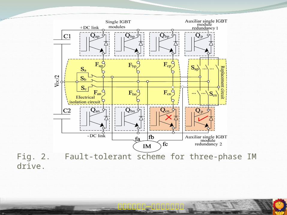
Fig. 2. Fault-tolerant scheme for three-phase IM drive.

南台科技大學─電力電子研究室
The detection and the location of the fault are the first and the most important events in a tolerant-system sequence, as shown in Fig. 3. After that, the tolerant mechanism is activated in order to guarantee process-operation continuity of the motor drive system used; the electrical isolation and the replacement of the damaged element are made possible by the activation of the isolation switches S(a,b,c) and connection switches S(a,b,c)(p,n)

南台科技大學─電力電子研究室
Fig. 3. Fault-tolerant sequence for an IM drive system.

南台科技大學─電力電子研究室
Fig. 4. IGBT equivalent circuit seen from the gate to emitter.

南台科技大學─電力電子研究室
The analysis of this technique is derived from the equivalent circuit seen from the gate to source of the IGBT. The region from the gate to drain of the IGBT is modeled by CGD , which is the most vulnerable region to fail because there is a great mobil- ity of carrier in the channel during the IGBT turn-on transient. This region is formed by variable capacitance CGDJ , which models the depletion zone, and a fixed capacitance COXD , which models the oxide zone

南台科技大學─電力電子研究室
Fig. 4 shows a simplified equivalent circuit that is seen from the gate to emitter obtained without taking into account the small modulation voltage of the base resistor and the small turn-on voltage of the diode of the internal bipolar junction transistor of the IGBT. Then, we assumed that the drain D and collector C terminals are equal. Therefore, the collector-to-emitter voltage VCE and the drain- to-source voltage VDS of the IGBT are considered equivalent

南台科技大學─電力電子研究室
Equation (1) is taken from the IGBT physical model and describes the behavior of the depletion gate–drain region
GSDS
siBGDGDJ VV
NqAC
2
.. (1)

南台科技大學─電力電子研究室
In the previous expression, the variation of some design and semiconductor-material parameters, such as the gate–drain area AGD and dielectric constant εsi , can cause a significant mod- ulation of CGDJ into the depletion region. Variation of these parameters can appear in the IGBT with destructive effect
The modulation of CGDJ also affects the characteristic equation of CGD in (2), which is defined by the transient behavior of VDS and VGS during the IGBT turn on (VDS > VGS )

南台科技大學─電力電子研究室
)(
./ GSDS
ifOXD
GSDSif
GDJOXD
GDJOXD
VVC
VVCC
CCGDC
(2)

南台科技大學─電力電子研究室
dt
tdVC
dt
tdVC
dt
tdVCI GS
GDDS
GDGS
GSG
)()()(
The gate current IG is deduced from the equivalent circuit that it is seen from the gate to emitter of the IGBT in Fig. 1 and is given by
(3)

南台科技大學─電力電子研究室
Fig. 5. Experimental gate charge.

南台科技大學─電力電子研究室
In the previous expression, it can be noted that IG is directlyaffected by CGD , which causes a significant change underthe IGBT gate voltage. The changes of the IGBT gate are characterized by three phases due to capacitance variations, and it is shown in Fig. 5 for a specific experiment of a chopper circuit when a constant gate current IG is forced to circulate during the IGBT turn on to have a better definition of the aforementioned behavior phases.

南台科技大學─電力電子研究室
The behavior during the turn on of the IGBT depends on theVGS and VDS voltage levels following different phases
Phase 1 (t1 < t < t2): At this point, VDS (t) is greater; then, the equivalent capacitance that it is seen from the gate to emitter of the IGBT only depends on CGS because at this point, CGDJ is smaller than COXD , and therefore, CGD is omitted to simplify the analysis.
Phase 2 (t2 < t < t3): This phase has the most complex be- havior because at this point, a plateau zone in the gate signal is generated by the Miller effect causing the first and third terms of IG (t) in (3) to be neglected by simplicity; then, the gate current IG (t) is determined only by the negative slope of VDS , a magnitude of CGD when CGD = COXD + CGDJ .

南台科技大學─電力電子研究室
Phase 3 (t3 < t < t4): During this phase and according to (2),the value of CGD can be considered equal to COXD be- cause VDS (t) acquires a smaller value than VGS (t) during IGBT turn-on; then, the total equivalent capacitance that is seen from the gate to emitter is the electrical parallel of COXD and CGS .

南台科技大學─電力電子研究室
Fig. 6. Simulation of gate-voltage signal varying AGD .

南台科技大學─電力電子研究室
In Fig. 6, the fault zone is shown during IGBT turn on; the fault can be evaluated from VT (threshold voltage) to upper gate voltage, which can assure full evaluation of the depletion region (VDS < VGS ); taking into account most of the IGBTs, the VT parameter is approximately a quarter of the gate–emitter saturation voltage continuous VGES , which commonly is
±20 V, and the plateau zone of the gate voltage is almost constant when the gate voltage is 5 V. Then, the threshold levels can be defined from VT to VT +5 V in order to
assure the existence of a depletion region (Phase 2). Additionally, the Phase 2 behavior can also be used to avoid physical destruction of the IGBT and to activate quickly the tolerant mechanisms in fast dynamic systems, such as the IM drive.

南台科技大學─電力電子研究室
Fig. 7. Experimental chopper circuit with resistive load.

南台科技大學─電力電子研究室
Fig. 7 shows an experimental test obtained in the IGBT gate signal for fault-free case and faulty case by short circuit caused by overtemperature and limited to nominal current in order to avoid fault propaga- tion. The signal obtained for the faulty case during short-circuit failure can be generalized for whatever application since the CGDJ is reduced when AGD and/or εsi are decreasing, which normally occur when there are thermal stress in the IGBT

南台科技大學─電力電子研究室
Fig. 8. Time diagram to determine the P 1 width and P 2 amplitude.

南台科技大學─電力電子研究室
Fig. 9. Fault-detection scheme in the IGBT based on the measurement and evaluation in the turn-on transient period.

南台科技大學─電力電子研究室
The P 1 pulsewidth is determined by a window detector, which is composed of a comparator circuit with hysteresis. This is capable of neglecting the turn-off phase, and thus, the limit of the detection window is established at the turn-on phase by means of two level comparators C 1 and C 2, which are tuned from the threshold voltage VT to VT +5 V in such a way that the width of P 1 may be proportional to the dynamics of the Phase 2 of gate signal VGE ∗of the IGBT. Note that VGE ∗is the
IGBT gate voltage but without the induced interference caused
by the emitter inductance Le .

南台科技大學─電力電子研究室
Fig. 10. Decision criterion. (a) Threshold voltage level. (b)
Diagnostic matrix.

南台科技大學─電力電子研究室
VGE = VG − K (VLe2 ) (4)
Where
VLe1 = (K − 1)VLe2 (5)
21
21
n)(1
)1(/ ee
if
eeif
LLnLLn
K
where n is the relationship Le2 /Le1 .

南台科技大學─電力電子研究室
Fig. 12. Fault-detection circuit implemented in the IGBT gate driver of IM drive. (a) Fault-tolerant system. (b) Scheme implemented.

南台科技大學─電力電子研究室
Fig. 13. Experimental test of detection circuit by different cases. (a) Failure by short circuit. (b) Failure-free. (c) Failure by open circuit.

南台科技大學─電力電子研究室
Fig. 13 shows the experimental results based on the detec- tion circuit proposed; the IGBT used is a discrete type IGBT (G4PH30K). The operating condition is set up by a collector current of IC = 10 A, and the test collector–emitter voltage VCE = 300 V. The failure-free and faulty conditions of the fault-detection circuit are emulated by reducing and extend- ing the gate-signal plateau. It is done by varying the gate resistance value RG significantly, e.g., the failure by short- circuit device is obtained by reducing RG = 0.1 Ω (RG1 ), the failure by open-circuit device is obtained by incrementing RG = 1 kΩ (RG2 ), and the failure-free condition is obtained by using RG = 100 Ω (RG3 ).

南台科技大學─電力電子研究室
Fig. 14. Experimental results under short-circuit failure.

南台科技大學─電力電子研究室
Fig. 14 shows the experimental results for current waveform applying the detection technique proposed for a failure by short circuit. The experimental conditions of the failure are as follows: Qcn fails by short circuit, the electrical isolation estimated is 5 ms after the fault detection, and replacement time of the damaged element is at the next zero crossing of the reference current of the motor.

南台科技大學─電力電子研究室
CONCLUSION A fault-detection circuit based on the IGBT gate-
voltage behavior has been proposed, and in addition, this fault-detection circuit has been implemented in the gate drive focused on a mo- tor drive. The delay time of the fault-detection circuit obtained is less than 3 μs; thus, this strategy is suitable for fault-tolerant motor drive since the nonlinearities of the inverter as death time, induced interference, and voltage peaks do not affect the fault-free operation of the fault-detection circuit in the inverter. A disadvantage of this strategy is that it is not generalized for every power device, although the proposed fault-detection circuit can also be applied with MOSFET because the current of the channel MOS in the gate voltage is similar. Another disadvantage is that the measurement of VLe2 that attenuates the induced interference adds an extra voltage sensor to the strategy proposed.

南台科技大學─電力電子研究室
REFERENCES [1] L. de Lillo, L. Empringham, P. W. Wheeler, S. Khwan-On, C. Gerada, M. N. Othman, and X. Huang,
“Multiphase power converter drive for fault-tolerant machine development in aerospace application,” IEEE Trans. Ind. Electron., vol. 57, no. 2, pp. 575–583, Feb. 2010.
[2] Z. Sun, J. Wang, D. Howe, and G. Jewell, “Analytical prediction of short-circuit current in fault-tolerant permanent magnet machines,” IEEE Trans. Ind. Electron., vol. 55, no. 12, pp. 4210–4217, Dec. 2008.
[3] A. Namazi, M. Nourani, and M. Saquib, “A fault-tolerant interconnect mechanism for NMR nanoarchitectures,” IEEE Trans. Very Large Scale Integr. (VLSI) Syst., vol. 18, no. 10, pp. 1433–1446, Oct. 2010. [4] S. Karimi, A. Gaillard, P. Poure, and S. Saadate, “FPGA-based real- time power converter failure diagnosis
for wind energy conversion systems,” IEEE Trans. Ind. Electron., vol. 55, no. 12, pp. 4299–4308, Dec. 2008. [5] Y. Xiong, X. Cheng, Z. J. Shen, C. Mi, H. Wu, and V. K. Garg, “Prognostic and warning system for power-electronic modules in electric, hybrid electric, and fuel-cell
vehicles,” IEEE Trans. Ind. Elec- tron., vol. 55, no. 6, pp. 2268–2276, Jun. 2008. [6] S. Bolognani, M. Zordan, and M. Zigliotto, “Experimental fault-tolerant control of a PMSM drive,” IEEE Trans. Ind. Electron., vol. 47, no. 5, pp. 1134–1141, Oct. 2000. [7] N. Bianchi and S. Bolognani, “Strategies for the fault-tolerant current control of five phase permanent-
magnetic motor,” IEEE Trans. Ind. Appl., vol. 43, no. 4, pp. 960–970, Jul./Aug. 2007. [8] B. A. Welchko, T. A. Lipo, T. M. Jahns, and S. E. Schulz, “Fault tolerant three-phase AC motor drive
topologies: A comparison of features, cost, and limitations,” IEEE Trans. Power Electron., vol. 19, no. 4, pp. 1108–1116, Jul. 2004.
[9] R. L. A. Ribeiro, C. B. Jacobina, E. R. C. da Silva, and A. M. N. Lima, “Fault-tolerant voltage-fed PWM inverter AC motor drive systems,” IEEE Trans. Ind. Electron., vol. 51, no. 2, pp. 439–446, Apr. 2004.
[10] P. Barriuso, J. Dixon, P. Flores, and L. Morán, “Fault tolerant reconfiguration system for asymmetric multilevel converters using bi-directional power switches,” IEEE Trans. Ind. Electron., vol. 56, no. 4, pp. 1300–1306, Mar. 2009.

南台科技大學─電力電子研究室
[11] M. A. Rodríguez, A. Claudio, D. Theillio, L. G. Vela, and L. Hernández, “Strategy to replace the damaged element for fault-tolerant induction motor drive,” in Proc. IEEE Appl. Power Electron. Conf., Washington, DC, Feb. 15–19, 2009, pp. 343–346.
[12] F. Zidani, D. Diallo, M. El Hachemi Benbouzid, and R. Naït-Saïd, “A fuzzy-based approach for the diagnosis of fault modes in a voltage-fed PWM inverter induction motor drive,” IEEE Trans. Ind. Electron., vol. 55, no. 2, pp. 586–593, Feb. 2008.
[13] J. Klima, “Analytical investigation of an induction motor drive under inverter fault mode operations,” Proc. Inst. Elect. Eng.—Elect. Power Appl., vol. 150, no. 3, pp. 255–262, May 2003.
[14] P. Lezana, R. Aguilera, and J. Rodríguez, “Fault detection on multicell converter based on output voltage frequency analysis,” IEEE Trans. Ind. Electron., vol. 56, no. 6, pp. 2275–2283, Jun. 2009. [15] F. Richardeau, P. Baudesson, and T. A. Meynard, “Failure-tolerance and remedial strategies of a PWM multicell inverter,” IEEE Trans. Power Electron., vol. 17, no. 6, pp. 905–912, Nov. 2002. [16] S. Caballos, J. Pou, E. Robles, J. Zaragoza, and J. L. Martín, “Performance evaluation of fault-tolerant neutral-point-clamped
converters,” IEEE Trans. Ind. Electron., vol. 57, no. 8, pp. 2709–2718, Aug. 2010. [17] T.-J. Klim, W.-C. Lee, and D. S. Hyun, “Detection method for open-circuit fault in neutral-point-clamped inverter systems,” IEEE Trans. Ind. Electron., vol. 56, no. 7, pp. 2754–2763, Jul. 2009. [18] B. Lu and S. Sharma, “A survey of IGBT fault diagnostic methods for three-phase power inverters,” in Proc. IEEE Int. Conf. Condition Monit.
Diagnosis, Apr. 2008, pp. 756–763. [19] B. Lu and S. Sharma, “A literature review of IGBT fault diagnostic and protection methods for power inverters,” IEEE Trans. Ind. Appl., vol.
45, no. 5, pp. 1770–1777, Sep./Oct. 2009. [20] W. Sleszynski, J. Nieznanski, and A. Cichowski, “Open-transistor fault diagnostics in voltage-source inverters by analyzing the load currents,” IEEE Trans. Ind. Electron., vol. 56, no. 11, pp. 4681–4688, Nov.
2009. [21] R. S. Chokhawala and S. Sobhani, “Switching voltage transient protection schemes for high-current IGBT modules,” IEEE Trans. Ind. Appl., vol. 33, no. 6, pp. 1601–1610, Nov./Dec. 1997. [22] R. S. Chokhawala, J. Catt, and L. Kiraly, “A discussion on IGBT short- circuit behavior and fault protection schemes,” IEEE Trans. Ind. Appl., vol. 31, no. 2, pp. 256–263, Mar./Apr. 1995. [23] R. Pagano, Y. Chen, K. Smedley, S. Musumeci, and A. Raciti, “Short circuit analysis and protection of power module IGBTs,” in Proc. IEEE Appl. Power Electron. Conf., Austin, TX, Feb. 19–23, 2005, pp. 777–783. [24] F. Huang and F. Flett, “IGBT fault protection based on di/dt feed- back control,” in Proc. IEEE Power Electron. Spec. Conf., 2007, pp. 1913–1917. [25] B. G. Park, J.-B. Lee, D.-S. Hyun, F. Huang, and F. Flett, “A novel short-circuit detecting scheme using turn-on switching characteristic of
IGBT,” in Conf. Rec. IEEE IAS Annu. Meeting, Edmonton, AB, Canada, Oct. 5–9, 2008, pp. 1–5. [26] R. L. de Araujo Ribeiro, C. B. Jacobina, E. R. C. da Silva, and A. M. N. Lima, “Fault detection of open-switch damage in voltage-fed
PWM motors drive systems,” IEEE Trans. Power Electron., vol. 18, no. 2, pp. 587–593, Mar. 2003. [27] S. F. Farag, R. G. Bartheld, and T. G. Habetler, “Integrated on-line motor protection system,” in Conf. Rec. IEEE IAS Annu. Meeting, Mar./Apr. 1996, vol. 2, pp. 21–26. [28] A. M. S. Mendes and A. J. Marques, “Voltage source inverter fault diagnosis in variable speed AC drives, by the average current Park’s
vector approach,” in Proc. IEMDC, 1999, pp. 704–706. [29] K. Rothenhagen and F. W. Fuchs, “Performance of diagnosis methods for IGBT open circuit faults in three phase voltage source inverters for
AC variable speed drives,” in Proc. Eur. Conf. Power Electron. Appl., Dresden, Germany, Sep. 2005, pp. 1–10. [30] A. Aviziens, “Fault-tolerant systems,” IEEE Trans. Comput., vol. C-25, no. 12, pp. 1304–1312, Dec. 1976. [31] R. Isermann, R. Schwarz, and S. Stölzl, “Fault-tolerant drive-by- wire system,” IEEE Control Syst. Mag., vol. 22, no. 5, pp. 64–81, Oct. 2002. [32] C. Yu, J. S. Yuan, and H. Yang, “MOSFET linearity performance degrada- tion subject to drain and gate voltage stress,” IEEE Trans. Device
Mater. Rel., vol. 4, no. 4, pp. 681–689, Dec. 2004. [33] A. R. Hefner, Jr. and D. L. Blackburn, “An analytical model for the steady-state and transient characteristics of the power insulated-gate
bipolar transistor,” Solid State Electron., vol. 31, no. 10, pp. 1513–1532, Oct. 1988. [34] A. H. Craing, R. H. Randall, and J. Yedinak, “IGBT ghost failures in boost topology circuits explained through third quadrant operation,” in
Proc. IEEE Appl. Power Electron. Conf., New Orleans, LA, 2000, vol. 2, pp. 1103–1108. [35] M. Trivedi and K. Shenai, “Failure mechanisms of IGBT’s under short-circuit and clamped inductive switching stress,” IEEE Trans.
Power Electron., vol. 14, no. 1, pp. 108–115, Jan. 1999.

南台科技大學─電力電子研究室
Thank you