Embed Size (px)
Citation preview

SP-6457 TDConcrete Saw
Operation Manual
Revision #1 (05/09/03)

2
FOR HELP & INFORMATIONCONTACT MULTIQUIPPlease have the Model and Serial Number on-hand when calling.
MAIN(M-F 7AM-5PM)
(PACIFIC STANDARD TIME)
MULTIQUIP INC.18910 WILMINGTION AVE.CARSON, CALIFORNIA 90746800-421-1244 or 310-537-3700
PARTS DEPARTMENT 800-427-1244 or 310-537-3700FAX: 800-672-7877 or 310-637-3284
SERVICE DEPARTMENT/TECHNICAL ASSISTANCE
800-428-1244 or 310-537-3700FAX: 310-537-1173
WARRANTY DEPARTMENT 888-661-4279 or 310-661-4279FAX: 310-537-1173
E-MAIL [email protected]
WEBSITE www.multiquip.com
3
Conventions
Throughout this manual, the following conventions are used to indicateimportant information.
!NOTE
Text set off like this presents clarifying information, specificinstructions, commentary, sidelights, or interesting points ofinformation.
CAUTION
Text set off like this indicates that failure to follow directions couldresult in damage to equipment.
WARNING
Text set off like this indicates that failure to follow directions couldresult in bodily harm or loss of life.
!NOTE
It is extremely important that the operator reads and understands thesafety and message section of this manual.

4
WARNINGCALIFORNIA – Proposition 65 Warning
Engine exhaust and some of its constituents, andsome dust created by power sanding, sawing,grinding, drilling and other construction activitiescontain chemicals known to the State of California tocause cancer, birth defects and other reproductiveharm. Some examples of these chemicals are:
o Lead from lead-based paints.o Crystalline silica from brick.o Cement and other masonry products.o Arsenic and chromium from chemically treated
lumber.
Your risk from these exposures varies, depending onhow often you do this type of work. To reduce yourexposure to these chemicals: ALWAYS work in awell-ventilated area, and work with approved safetyequipment, such as duct masks that are specially
designed to filter out microscopic particles.

5
TABLE OF CONTENTS
CONVENTIONS.................................................................................................................. 3
SAFETY..............................................................................................................................7
OPERATION....................................................................................................................19
BEFORE STARTING ......................................................................................................... 19ENGINE POWER, CUTTING POWER & SHEAVE SIZE........................................................ 20
Blade RPM vs Surface Feet Per Minute (SFPM)...................................................... 22Stacking Blades for Wide Cuts.................................................................................. 24
WATER SUPPLY AND CONTROL...................................................................................... 28CONTROL PANEL............................................................................................................ 29HANDLEBARS................................................................................................................. 30FUELING THE SAW......................................................................................................... 31STARTING AND STOPPING THE ENGINE.......................................................................... 32COLD WEATHER OPERATION ......................................................................................... 33
Glow Plugs................................................................................................................ 33Block Heaters ............................................................................................................ 33Draining the Water System ....................................................................................... 33
POINTER ADJUSTMENT................................................................................................... 34RAISE — LOWER CONTROLS.......................................................................................... 35SETTING THE DEPTH GAUGE & DEPTH STOP ................................................................. 36DRIVE SYSTEM............................................................................................................... 37
Transaxle................................................................................................................... 384-Speed BladeShaft ................................................................................................... 39Shifting Gears ........................................................................................................... 40
NIGHT LIGHT.................................................................................................................. 41TRANSPORTATION TIE-DOWNS AND LIFT POINT............................................................ 41

6
MAINTENANCE.............................................................................................................43
REMOVABLE GUARDS AND ACCESS PANELS .................................................................. 43BELTS AND PULLEYS ..................................................................................................... 44
V-Belt Tension........................................................................................................... 44Adjusting BladeShaft Drive Belt Tension................................................................. 46Replacing the BladeShaft Belt: ................................................................................. 46Replacing the Jackshaft Belt ..................................................................................... 46
BLADESHAFT MAINTENANCE......................................................................................... 48BladeShaft Replacement ........................................................................................... 48
BLADE COLLAR REMOVAL/INSTALLATION .................................................................... 49CIRCUIT BREAKERS........................................................................................................ 52MAXIMUM CUT DEPTH ADJUSTMENT ............................................................................ 52LUBRICATION................................................................................................................. 53ENGINE........................................................................................................................... 54
Air and Oil Filter Chart ............................................................................................ 54PTO DRIVE MAINTENANCE ........................................................................................... 55REPLACING THE BATTERY.............................................................................................. 57RAISE-LOWER SYSTEM .................................................................................................. 58JOYSTICK TENSION ADJUSTMENT .................................................................................. 59HYDRAULIC SYSTEM MAINTENANCE ............................................................................. 60
Routine Maintenance ............................................................................................... 60Draining & Filling the Hydraulic System................................................................. 61Bleeding the Depth Stop Cylinder............................................................................. 63
DRIVE WHEEL ALIGNMENT............................................................................................ 64
SPECIFICATIONS..........................................................................................................66
DIMENSIONS..................................................................................................................67
6457 ELECTRICAL SCHEMATIC ….. ............................................................................... 68
!NOTE
Specifications are subject to change without notice.
7
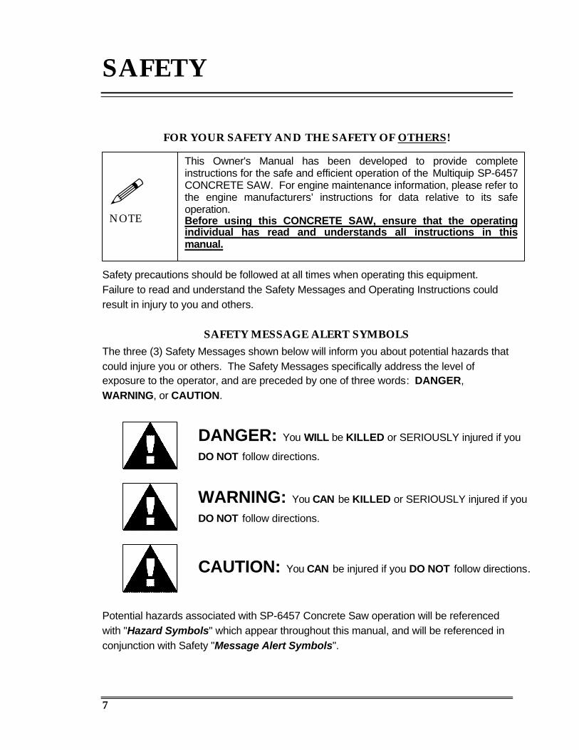
SAFETY
FOR YOUR SAFETY AND THE SAFETY OF OTHERS!
Safety precautions should be followed at all times when operating this equipment.Failure to read and understand the Safety Messages and Operating Instructions couldresult in injury to you and others.
SAFETY MESSAGE ALERT SYMBOLSThe three (3) Safety Messages shown below will inform you about potential hazards thatcould injure you or others. The Safety Messages specifically address the level ofexposure to the operator, and are preceded by one of three words: DANGER,WARNING, or CAUTION.
Potential hazards associated with SP-6457 Concrete Saw operation will be referencedwith "Hazard Symbols" which appear throughout this manual, and will be referenced inconjunction with Safety "Message Alert Symbols".
DANGER: You WILL be KILLED or SERIOUSLY injured if you
DO NOT follow directions.
This Owner's Manual has been developed to provide completeinstructions for the safe and efficient operation of the Multiquip SP-6457CONCRETE SAW. For engine maintenance information, please refer tothe engine manufacturers’ instructions for data relative to its safeoperation.Before using this CONCRETE SAW, ensure that the operatingindividual has read and understands all instructions in thismanual.
WARNING: You CAN be KILLED or SERIOUSLY injured if you
DO NOT follow directions.
CAUTION: You CAN be injured if you DO NOT follow directions.
!NOTE
8
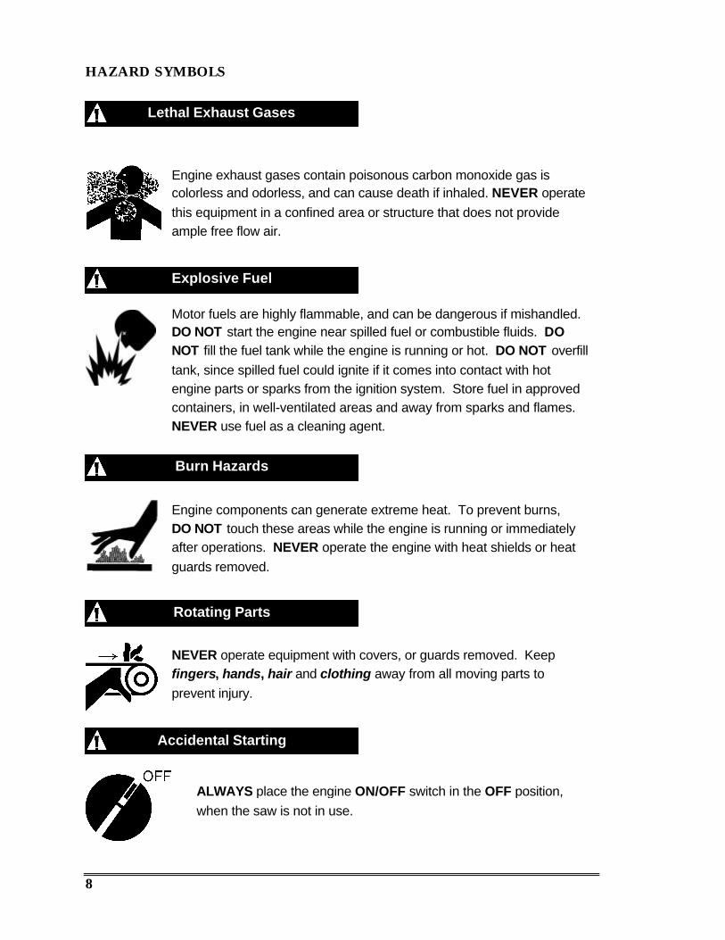
HAZARD SYMBOLS
Lethal Exhaust Gases
Engine exhaust gases contain poisonous carbon monoxide gas iscolorless and odorless, and can cause death if inhaled. NEVER operatethis equipment in a confined area or structure that does not provideample free flow air.
Explosive Fuel
Motor fuels are highly flammable, and can be dangerous if mishandled.DO NOT start the engine near spilled fuel or combustible fluids. DONOT fill the fuel tank while the engine is running or hot. DO NOT overfilltank, since spilled fuel could ignite if it comes into contact with hotengine parts or sparks from the ignition system. Store fuel in approvedcontainers, in well-ventilated areas and away from sparks and flames.NEVER use fuel as a cleaning agent.
Burn Hazards
Rotating Parts
Engine components can generate extreme heat. To prevent burns,DO NOT touch these areas while the engine is running or immediatelyafter operations. NEVER operate the engine with heat shields or heatguards removed.
NEVER operate equipment with covers, or guards removed. Keepfingers, hands, hair and clothing away from all moving parts toprevent injury.
Accidental Starting
ALWAYS place the engine ON/OFF switch in the OFF position,when the saw is not in use.
9
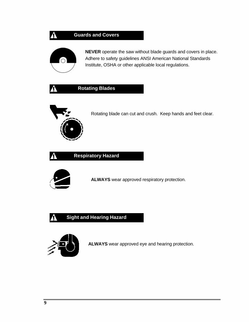
ALWAYS wear approved respiratory protection.
Guards and Covers
Rotating Blades
Respiratory Hazard
Sight and Hearing Hazard
NEVER operate the saw without blade guards and covers in place.Adhere to safety guidelines ANSI American National StandardsInstitute, OSHA or other applicable local regulations.
Rotating blade can cut and crush. Keep hands and feet clear.
ALWAYS wear approved eye and hearing protection.
10
Equipment Damage Messages
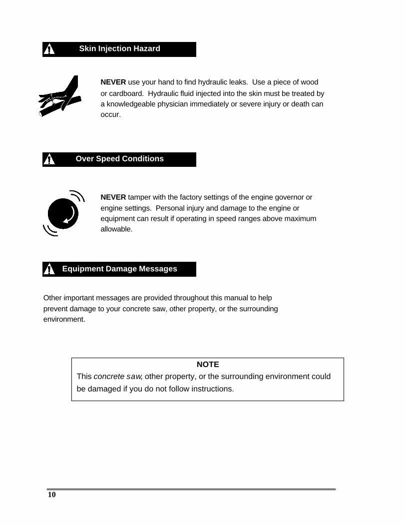
Skin Injection Hazard
NEVER use your hand to find hydraulic leaks. Use a piece of wood
or cardboard. Hydraulic fluid injected into the skin must be treated bya knowledgeable physician immediately or severe injury or death canoccur.
Other important messages are provided throughout this manual to helpprevent damage to your concrete saw, other property, or the surroundingenvironment.
NOTEThis concrete saw, other property, or the surrounding environment could
be damaged if you do not follow instructions.
Over Speed Conditions
NEVER tamper with the factory settings of the engine governor orengine settings. Personal injury and damage to the engine orequipment can result if operating in speed ranges above maximumallowable.
11
RULES FOR SAFE OPERATION
Most accidents involving product operation, maintenance and repair are causedby failure to observe basic safety rules and precautions. Accidents can often beavoided by recognizing potentially hazardous situations before an incidentoccurs.
General Safety Warnings
WARNING
§ DO NOT operate or service this equipment before reading thisentire manual. Failure to follow instructions may lead to seriousinjury or death.
§ This equipment is to be operated by trained and qualifiedpersonnel only. This equipment should not be operated bypersons under 18 years of age.
§ This equipment is for industrial use and to be used for itsintended purpose only.
§ NEVER operate this equipment when not feeling well due tofatigue, illness or taking medicine.
§ NEVER operate the saw under the influence of drugs or alcohol.
§ NEVER use accessories or attachments, which are notrecommended by Multiquip for this equipment. Damage to theequipment and/or injury to user may result. Manufacturer doesnot assume responsibility for any accident due to equipmentmodifications. Unauthorized equipment modification will void allwarranties.
§ NEVER operate this saw without proper protective clothing;shatterproof glasses, steel-toed boots, respiration mask, and anyother protective devices required by the job.
12
WARNING
§ Before operating the saw, make sure all protective guards aresecurely in place. Multiquip saws are supplied with a blade guard,collar guard and belt guard.
§ Whenever necessary, replace operation and safety decals if theybecome difficult to read.
§ Verify the engine start switch is set to the OFF position beforeinstalling a blade.
§ Make sure the operator knows how to turn the engine OFF in caseof an emergency.
§ Do not go near rotating parts (blades, belts, pulleys or wheels)while engine is running.
§ Catalytic muffler and exhaust gases are extremely hot. Stay clearof muffler and exhaust gases. Allow these parts to cool beforeservicing the saw.
§ Stay clear of the saw while it is being hoisted.
§ Anytime the saw is lifted onto its nose, or tilted fully back, formaintenance access, the high end MUST be blocked up to preventthe possibility of crush injury!
§ Allow the engine to cool before adding fuel or performing serviceand maintenance functions. Contact with HOT components cancause serious burns.
§ Never operate the saw in any enclosed or narrow area where freeflow of air is restricted. If the air flow is restricted it will causeserious damage to the saw’s engine and may cause injury topeople. Remember the saw’s engine gives off DEADLY carbonmonoxide gas.
§ ALWAYS refuel in a well-ventilated area; away from sparks andopen flame. Avoid “topping off” the filler port as spills can result.
§ ALWAYS use extreme caution when working with flammableliquids. When refueling, STOP the engine and allow it to cool.
§ NEVER smoke around or near the machine. Fire or explosioncould result from fuel vapors, or if fuel is spilled on a HOT engine.
§ NEVER operate the saw in an explosive atmosphere where fumesare present or near combustible materials. An explosion or firecould result causing severe bodily harm or even death.
§ NEVER use fuel as a cleaning agent.

13
General Safety Precautions
CAUTION
§ ALWAYS read, understand, and follow procedures in theOperator’s Manual before attempting to operate the equipment.
§ Be sure the operator is familiar with proper safety precautionsand operating techniques before using the saw.
§ Make sure the operating area is clear before starting the engine.
§ Maintain this equipment in a safe operating condition at all times.
§ Keep the saw clean. It will work better and last longer.
§ Use proper blades and follow the blade manufacturer’srecommendations. Match blade rpm (Blade Shaft rpm) torecommended blade surface feet per minute (SFPM).
§ Tighten the 5/8” blade-mounting bolt to 100-125 foot-lbs. torque.
§ Turn engine OFF prior to fueling the saw.
§ Start engine with the joystick in NEUTRAL to prevent unexpectedsaw movement.
§ Do not leave saw unattended while engine is running.
§ Do not start engine on a sloping surface to prevent unexpectedloss of control.
§ Do not park or leave saw unattended on a slope - the saw can rollwhen the engine is OFF. Block the unit when leaving.
§ If the saw must be parked on a slope, turn it across the angle ofthe slope, to prevent accidental downhill movement.
§ Always store equipment properly when not being used. Equipmentshould be stored in a clean, dry location out of the reach ofchildren. When storing the saw in freezing weather, blow outwater lines to prevent damage to components in the waterdelivery system.
§ Prior to service, level the frame surface.
§ Do not over tighten the Blade Shaft drive belt.
§ Turn on water flow prior to starting the engine, to preventdamage to the impeller of a belt-driven water pump.
§ Don’t pollute! Waste oils and other chemicals must be disposedof in a manner consistent with local and state environmentalprotection regulations.
14
BLADE SAFETY
WARNING
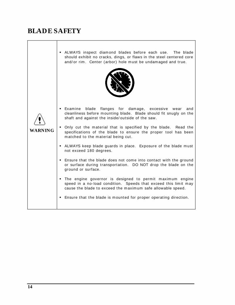
§ ALWAYS inspect diamond blades before each use. The bladeshould exhibit no cracks, dings, or flaws in the steel centered coreand/or rim. Center (arbor) hole must be undamaged and true.
§ Examine blade flanges for damage, excessive wear andcleanliness before mounting blade. Blade should fit snugly on theshaft and against the inside/outside of the saw.
§ Only cut the material that is specified by the blade. Read thespecifications of the blade to ensure the proper tool has beenmatched to the material being cut.
§ ALWAYS keep blade guards in place. Exposure of the blade mustnot exceed 180 degrees.
§ Ensure that the blade does not come into contact with the groundor surface during transportation. DO NOT drop the blade on theground or surface.
§ The engine governor is designed to permit maximum enginespeed in a no-load condition. Speeds that exceed this limit maycause the blade to exceed the maximum safe allowable speed.
§ Ensure that the blade is mounted for proper operating direction.
15
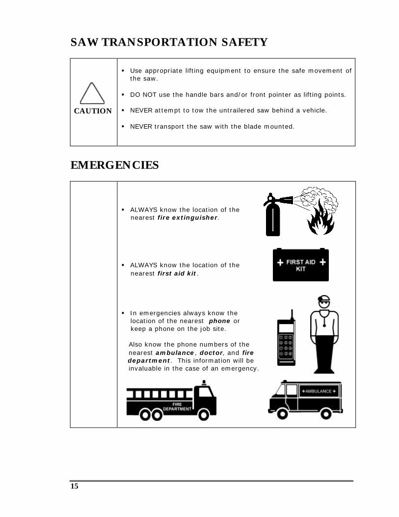
SAW TRANSPORTATION SAFETY
CAUTION
§ Use appropriate lifting equipment to ensure the safe movement ofthe saw.
§ DO NOT use the handle bars and/or front pointer as lifting points.
§ NEVER attempt to tow the untrailered saw behind a vehicle.
§ NEVER transport the saw with the blade mounted.
EMERGENCIES
§ ALWAYS know the location of the nearest fire extinguisher.
§ ALWAYS know the location of the nearest first aid kit.
§ In emergencies always know the location of the nearest phone or keep a phone on the job site.
Also know the phone numbers of the nearest ambulance, doctor, and fire department. This information will be invaluable in the case of an emergency.
16
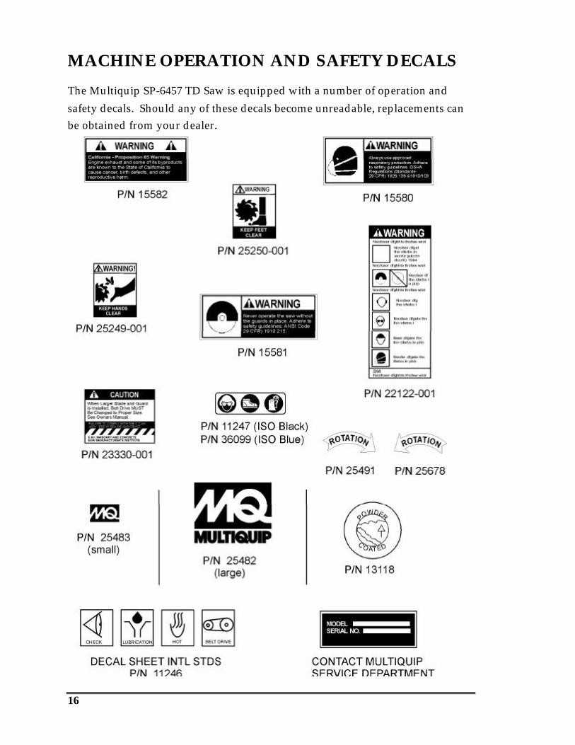
MACHINE OPERATION AND SAFETY DECALS
The Multiquip SP-6457 TD Saw is equipped with a number of operation andsafety decals. Should any of these decals become unreadable, replacements canbe obtained from your dealer.

17
Serial Tag
Fig. 1 — Serial Tag
!NOTE
For future reference, fill in the model number and serial number ofyour saw in the spaces on the label above.
The serial tag contains the model number and serial number of the saw. Thisinformation details all parts that were included with the saw when it wasshipped from the factory, as well as the date of manufacture.
Record these numbers, in case you need to contact Multiquip in the future.
Record your ENGINE model, specification number and serial number here:
MODEL NO. SPEC. NO. SERIAL NO.
The SERIAL TAG is bonded to the panel forward of the console (between the
console and the engine. (See Figure 2.)

18
SERIAL TAGENGINE SERIAL
NUMBERS
Fig. 2 — Serial Number Locations
!NOTE
§ The 5/8” blade-mounting bolt on the right side of the saw (asviewed from the operator’s position) has a left hand thread, whilethe blade-mounting bolt on the left side of the saw has a righthand thread.
§ Most saw hardware is measured in English (inch) units. TheIllustrated Parts List notes any Metric hardware. Be sure to use thecorrect hardware and proper tools.

19
OPERATION
Before Starting
Before starting the saw, carefully follow the checklist below:
r Securely install the Belt Guard (2).
r Fully slide on the Collar Guard (3).
r Verify that proper-sized Blade Guard (4) is fully installed on the Blade
Guard mounting tab.
r Confirm the rear and side access panels (5) (6)& (7) and engine
protector are in place.
r Wear eye and hearing protection and protective clothing.
r Adjust handle bars (1) for best operator control.
r If a belt driven water pump is installed, do not run the engine with thewater pump switch on, unless the water supply is connected andwater is flowing.
Fig. 3 — Guards & Panels

20
Engine Power, Cutting Power & Sheave Size
The cutting capability of your saw is a relationship between engine power (asreflected in the engine RPM) and the speed (RPM) of the Blade Shaft. The dieselengine of the SP-6457 TD runs at 2800 RPM (full load). If 2800 RPM was adesirable Blade Shaft speed for the average conditions in which you work, wewould use the same size sheave on the engine shaft and the Blade Shaft; and theratio between the two would be 1 : 1.
Fig. 4 — Blade Shaft Ratios
If, however, for your cutting conditions, you need a Blade Shaft speed slowerthan the engine speed (and this is usually the case), then we need to INCREASEthe ratio between the two speeds by putting a larger diameter sheave on theBlade Shaft. This, in effect, is what occurs when you shift gears on the SP-6457TD.
If, for example, you know from experience that you need a Blade Shaft speed of2000 RPM for the size of blade you normally use (see the Blade RPM vs. SFPMChart, below):
2800 (engine RPM) ÷ 2000 (desired BS RPM) = 1.4
This is the ratio 1.4 : 1, which means that for every 1.4 revolutions of the engine,the Blade Shaft only turns once.
Ratios greater than 1 : 1 also have the beneficial effect of increasing the torque ofthe Blade Shaft by the same factor (1.4 in our example) . The manufactureradvertises that the Deutz BF31011 diesel engine develops 123 ft. lbs. of torque.To find the theoretical torque of our example saw setup:
123 x 1.4 = 172.2 ft. lbs.
Actual torque of the saw will vary somewhat. In general, more torque meansmore cutting power.
1 : 1 1.4 : 1
Blade ShaftBlade Shaft
EngineEngine

21
Typically, however, the ratios are not used to design a level of torque; they areused to create a saw with the optimum blade speed (blade Shaft RPM) for you.The major factors are:
• diameter of blade(s) you commonly use, and• cutting conditions you work under
The 4 gear ratios we have designed into the SP-6457 TD 4-speed Blade Shaft are:
1st Gear 1.00 : 12nd Gear 1.34 : 13rd Gear 1.70 : 14th Gear 2.02 : 1
In addition to the four” fixed” ratios of the Blade Shaft gears, we can also tailorthe Blade Shaft RPM (blade speed) by adjusting the “primary” ratio between theengine and the Blade Shaft. By selecting a Blade Shaft sheave and Engine sheave,a multitude of additional ratios (and Blade Shaft speeds) are possible. Thefollowing Sheave sets are available as standard kits:
5.1 6.0 1.17 : 1
2333 in 1st 1741 in 2nd1372 in 3rd1154 in 4th
2800 18609
5.4 5.6 1.03 : 1
2700 in 1st 2000 in 2nd1588 in 3rd1350 in 4th
2800 18611
6.0 5.0 .83 : 1
3373 in 1st 2498 in 2nd1984 in 3rd1686 in 4th
2800 18612
EngineSheave
Blade ShaftSheave Ratio Blade Shaft RPM
EngineRPM Kit #

22
Blade RPM vs. Surface Feet Per Minute (SFPM)
When choosing a blade for your cutting conditions, follow the blademanufacturer’s recommendations. Match the blade speed (Blade Shaft RPM) tothe recommended blade Surface Feet Per Minute (SFPM).
SFPM 16”
diam.RPM
18”
diam.RPM
20”
diam.RPM
24”
diam.RPM
26”
diam.RPM
30”
diam.RPM
36”
diam.RPM
42”
diam.RPM
48”
diam.RPM
8,000 1910 1698 1528 1273 1175 1019 849 728 636
8,500 2029 1804 1623 1353 1249 1082 902 773 676
9,000 2149 1910 1719 1432 1322 1146 955 819 716
9,500 2268 2016 1814 1512 1396 1210 1008 864 756
10,000 2387 2122 1910 1592 1469 1273 1061 910 796
10,500 2507 2228 2005 1671 1543 1337 1114 955 836
11,000 2626 2334 2101 1751 1616 1401 1167 1001 875
11,500 2745 2440 2196 1830 1690 1464 1220 1046 915
12,000 2865 2546 2292 1910 1763 1528 1273 1092 955
12,500 2984 2653 2387 1989 1836 1592 1326 1137 995
13,000 3104 2759 2483 2069 1910 1655 1378 1183 1035
13,500 3229 2866 2581 2149 1985 1719 1433 1228 1074
14,000 3349 2972 2676 2229 2058 1783 1486 1273 1114
14,500 3468 3078 2772 2308 2132 1847 1532 1319 1153
CAUTION
§ Verify that the engine start switch is OFF before installing blade.
§ Tighten the 5/8” blade-mounting bolt to125-175 foot-pounds torque.

23
Installing the Blade
The blade can be mounted on either side of the saw to accommodate differentcutting jobs.1. Raise the saw so that the blade will clear the ground when installed.2. Verify that blade collars are clean and undamaged.3. Insert the bushing and mounting bolt through the outer collar and blade.
• Align collar pin through the blade into the inner collar.4. Tighten the 5/8” mounting bolt to 125-175 foot-pounds of torque.
• The blade-mounting bolt on the right side of the saw (as viewed from theoperator’s position) has a left hand-thread, while the blade-mounting bolton the left side of the saw has a right-hand thread.
Fig. 5 — Installing the Blade
Blade GuardMounting Clip
Inner Collar
TaperedBlade Shaft
Outer Collarwith Pin
CollarBushing
MountingBolt
24
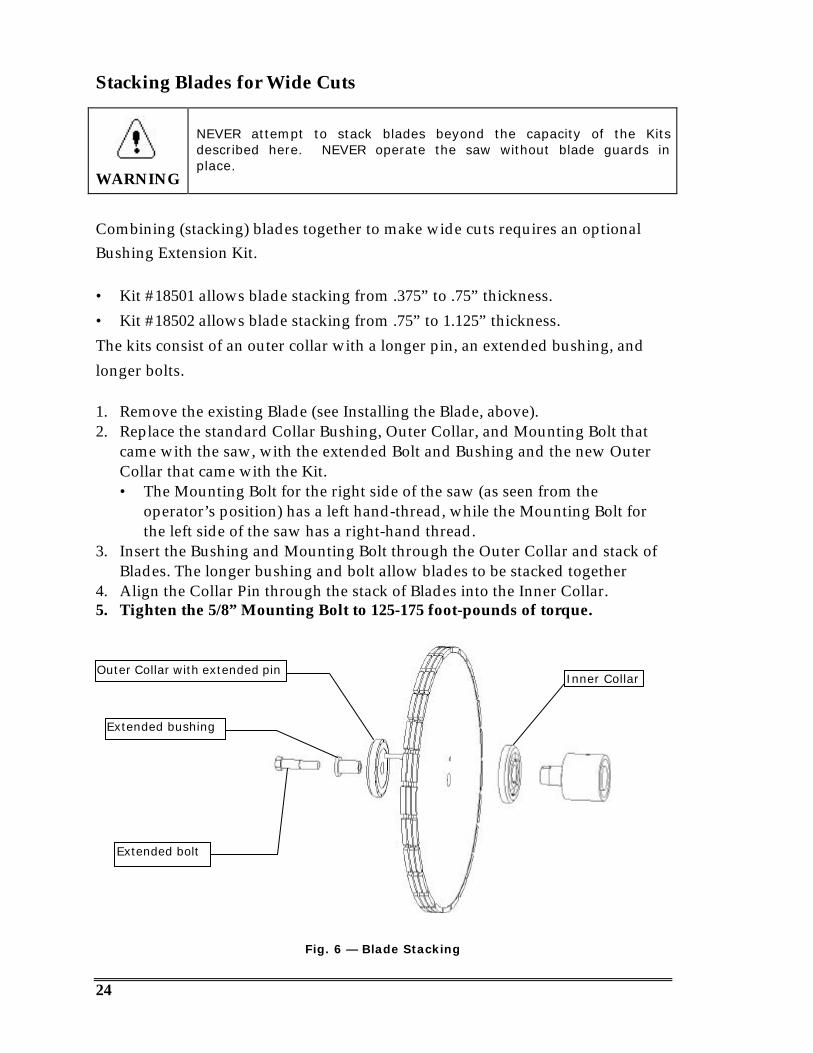
Stacking Blades for Wide Cuts
WARNING
NEVER attempt to stack blades beyond the capacity of the Kitsdescribed here. NEVER operate the saw without blade guards inplace.
Combining (stacking) blades together to make wide cuts requires an optionalBushing Extension Kit.
• Kit #18501 allows blade stacking from .375” to .75” thickness.• Kit #18502 allows blade stacking from .75” to 1.125” thickness.The kits consist of an outer collar with a longer pin, an extended bushing, andlonger bolts.
1. Remove the existing Blade (see Installing the Blade, above).2. Replace the standard Collar Bushing, Outer Collar, and Mounting Bolt that
came with the saw, with the extended Bolt and Bushing and the new OuterCollar that came with the Kit.• The Mounting Bolt for the right side of the saw (as seen from the
operator’s position) has a left hand-thread, while the Mounting Bolt forthe left side of the saw has a right-hand thread.
3. Insert the Bushing and Mounting Bolt through the Outer Collar and stack ofBlades. The longer bushing and bolt allow blades to be stacked together
4. Align the Collar Pin through the stack of Blades into the Inner Collar.5. Tighten the 5/8” Mounting Bolt to 125-175 foot-pounds of torque.
Fig. 6 — Blade Stacking
Extended bolt
Extended bushing
Outer Collar with extended pinInner Collar
25
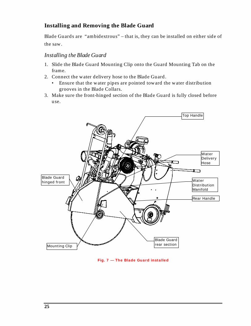
Installing and Removing the Blade Guard
Blade Guards are “ambidextrous” – that is, they can be installed on either side ofthe saw.
Installing the Blade Guard1. Slide the Blade Guard Mounting Clip onto the Guard Mounting Tab on the
frame.2. Connect the water delivery hose to the Blade Guard.
• Ensure that the water pipes are pointed toward the water distributiongrooves in the Blade Collars.
3. Make sure the front-hinged section of the Blade Guard is fully closed beforeuse.
Fig. 7 — The Blade Guard installed
Blade Guardrear sectionMounting Clip
Blade Guardhinged front
WaterDeliveryHose
Top Handle
Rear Handle
WaterDistributionManifold
26
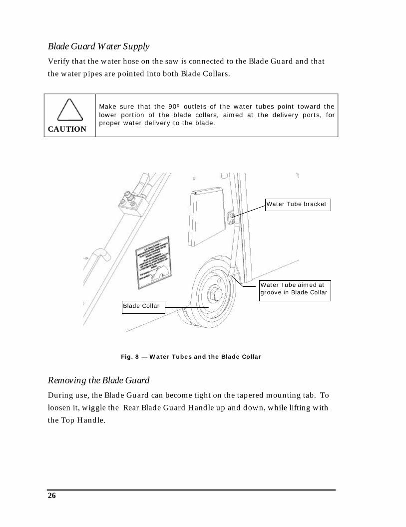
Blade Guard Water SupplyVerify that the water hose on the saw is connected to the Blade Guard and thatthe water pipes are pointed into both Blade Collars.
CAUTION
Make sure that the 90º outlets of the water tubes point toward thelower portion of the blade collars, aimed at the delivery ports, forproper water delivery to the blade.
Fig. 8 — Water Tubes and the Blade Collar
Removing the Blade GuardDuring use, the Blade Guard can become tight on the tapered mounting tab. Toloosen it, wiggle the Rear Blade Guard Handle up and down, while lifting withthe Top Handle.
Blade Collar
Water Tube aimed atgroove in Blade Collar
Water Tube bracket
27
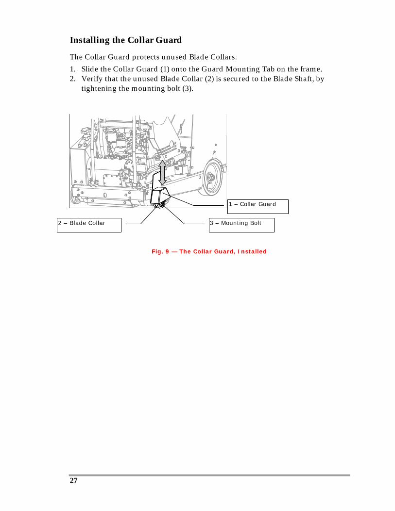
Installing the Collar Guard
The Collar Guard protects unused Blade Collars.1. Slide the Collar Guard (1) onto the Guard Mounting Tab on the frame.2. Verify that the unused Blade Collar (2) is secured to the Blade Shaft, by
tightening the mounting bolt (3).
Fig. 9 — The Collar Guard, Installed
1 – Collar Guard
3 – Mounting Bolt2 – Blade Collar
28
Water Supply and Control
CAUTION
§ To prevent damage to the impeller of a belt driven water pump, donot run the engine with the water pump switch on, unless thewater supply is connected and water is flowing.
§ When storing the saw during freezing weather, blow out the waterlines to prevent damage to the water delivery system.
1. Connect the water supply hose to the water inlet (garden hose) fitting (1) onthe left side of the saw.
2. Verify that the water hose on the saw is connected to the Blade Guard (5) andthat the water tubes are pointed into both Blade Collars.
3. The yellow lever (4) on left side of the control panel regulates water flowvolume. The other lever (3) turns the water On and Off.
4. If the saw is equipped with an optional water pump, the ON/OFF switch (2)is on the control panel next to the water flow control valve.
!NOTE
Because of the water delivery efficiency of the 24-port blade collars,your saw will use less water for blade lubrication than other waterdeliver systems.
Fig. 10 — The Water Supply System
1
2
3
4
5
29
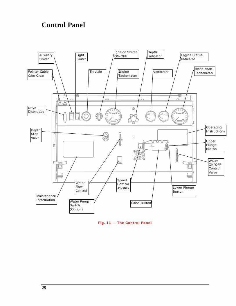
Control Panel
Fig. 11 — The Control Panel
EngineTachometer
AuxiliarySwitch
LightSwitch
VoltmeterThrottle
Ignition SwitchON-OFF
UpperPlungeButton
OperatingInstructions
SpeedControlJoystick
Water PumpSwitch(Option)
MaintenanceInformation
WaterFlowControl
DepthIndicator Engine Status
Indicator
DriveDisengage
DepthStopValve
WaterON/OFFControlValve
Raise Button
Pointer CableCam Cleat
Blade shaftTachometer
Lower PlungeButton

30
Handlebars
The handlebars are adjustable to three different angles, for optimum operatorcontrol, and can also be slid fully inward for storage. Once handlebars areadjusted, lock them into position by tightening the lock knob on each side.
Fig. 12 — Handlebar Positions
Using the handlebars in position #2 or #3 when employing larger diameterblades, reduces the need to bend over, and reduces the effort required by theoperator to maneuver the saw.
Threeoperatingpositions
Storageposition
Lock Knob
P3
P2
P1

31
Fueling the Saw
The saw features a 10-gallon, clear, molded plastic fuel tank with a sight gauge,central drain, and shutoff valve. The fuel tank cap is located at the front of thecontrol console.
CAUTION
§ Be sure the engine is turned off prior to fueling the saw.§ Do not spill diesel fuel on control panel or engine.§ Do not over-tighten gas cap.
WARNING
Use
Fig. 13 — Fuel System
Fuel Tank Cap
Sight Gauge
Shut-off Valve
32
Starting and Stopping The Engine
CAUTION
§ Do not leave the saw unattended while the engine is running.§ Do not start, park, or leave the saw unattended on a slope.§ If the saw has an optional water pump, do not run the saw dry
with the water pump switch ON — otherwise the pump impellerswill be damaged.
§ Do not stop the engine abruptly when hot! Reduce the throttle toidle and allow the engine to run one or two minutes before turningthe ignition switch off. This allows the engine to cool down, andprevents damage to the Turbo unit.
1. Move the speed control joystick to NEUTRAL position.2. Set the throttle to IDLE.3. Ensure that water lines are attached and water is flowing to the saw.4. Momentarily turn the ignition switch to the START position.
• Allow the engine to warm up for several minutes.5. Set the throttle to the recommended engine RPM to match the recommended
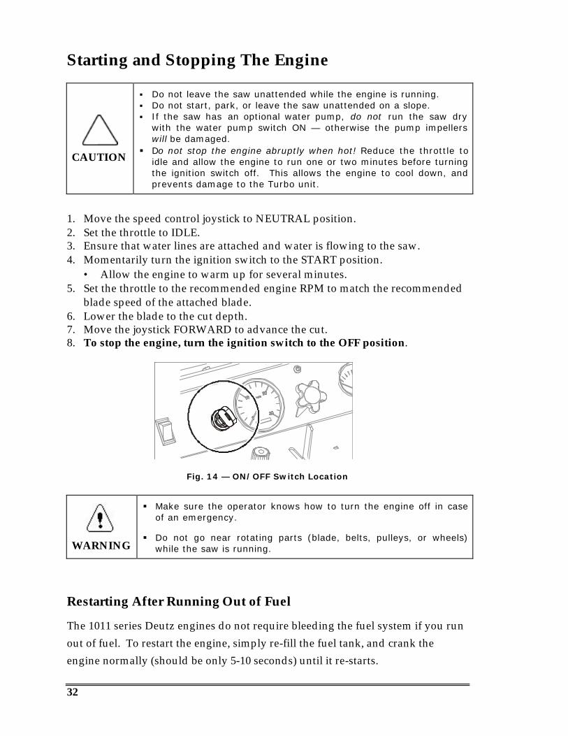
blade speed of the attached blade.6. Lower the blade to the cut depth.7. Move the joystick FORWARD to advance the cut.8. To stop the engine, turn the ignition switch to the OFF position.
Fig. 14 — ON/OFF Switch Location
WARNING
§ Make sure the operator knows how to turn the engine off in caseof an emergency.
§ Do not go near rotating parts (blade, belts, pulleys, or wheels)while the saw is running.
Restarting After Running Out of Fuel
The 1011 series Deutz engines do not require bleeding the fuel system if you runout of fuel. To restart the engine, simply re-fill the fuel tank, and crank theengine normally (should be only 5-10 seconds) until it re-starts.
33
Cold Weather Operation
Glow Plugs
Optional Glow Plugs are installed inside the air intake. In cold weather (lowtemperatures below 40°F):
1. Rotate the Ignition Switch PAST the ON position to the GLOW PLUGposition and HOLD there for 20-40 seconds.
2. After 20-40 seconds, continue to rotate the switch to the START position.3. Once the engine has started, let the switch go-it will return to the ON
position.
In extreme cold weather (below 20°F), 2 or 3 cycles of Glow Plug may benecessary before the engine will start.
Block Heaters
Optional Block Heaters, (installed directly on the crankcase), are operated byplugging them into an electrical outlet via an extension cord. The block heater isNOT thermostatically controlled. Use only just prior to saw use. DO NOT leavethe saw unattended with block heater in operation and DO NOT use when lowtemperatures are above 20°F.
CAUTION
§ Do not leave optional Block Heaters plugged in for extendedperiods when temperatures may rise above 20°F. The oil could“cook” inside the crankcase and damage to the engine couldresult.
§ If the Water System is not drained when the saw is not in use andtemperatures fall below 32°F, damage may occur to optional waterpumps and/or oil coolers.
Draining the Water System
When low temperatures fall below 32°F:1. If the saw is equipped with an optional Water Pump, open the drain petcock
on the pump and allow the pump to drain.• With the engine running, turn the water pump switch on for a few
seconds to purge water remaining inside the pump body.2. Tilt the saw up and back, to allow water to drain.3. Tilt the saw forward, to allow water to drain again.

34
4. If an air compressor is available, blow out the system by applyingcompressed air to the Water Inlet (see Fig. 10).
Pointer Adjustment
1. Lower the front pointer assembly.• Adjust the pointer rod (1) by loosening the lock knob (2).• Once the pointer rod is set to the cut line, tighten the lock knob.
2. Adjust the rear pointer to the cut line:• Loosen the lock bolt, position the pointer rod, and tighten the lock bolt.
3. To raise the front pointer assembly, pull back and up on the pointer cable (3).• Secure the pointer assembly in the desired raised position by locking the
cable between the jaws of the cam cleat (5).
Fig. 15 — Pointer Adjustment
1
2
3
4
5
6
35
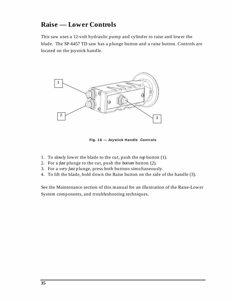
Raise — Lower Controls
This saw uses a 12-volt hydraulic pump and cylinder to raise and lower theblade. The SP-6457 TD saw has a plunge button and a raise button. Controls arelocated on the joystick handle.
Fig. 16 — Joystick Handle Controls
1. To slowly lower the blade to the cut, push the top button (1).2. For a fast plunge to the cut, push the bottom button (2).3. For a very fast plunge, press both buttons simultaneously.4. To lift the blade, hold down the Raise button on the side of the handle (3).
See the Maintenance section of this manual for an illustration of the Raise-LowerSystem components, and troubleshooting techniques.
1
23
36
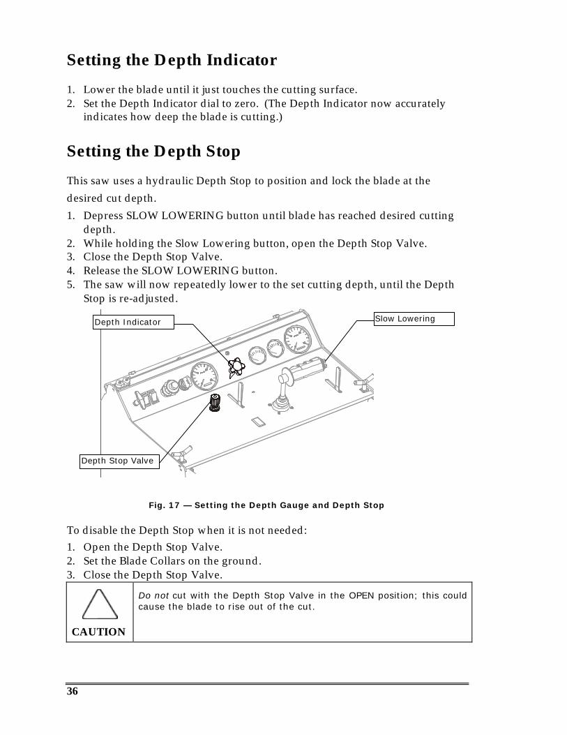
Setting the Depth Indicator
1. Lower the blade until it just touches the cutting surface.2. Set the Depth Indicator dial to zero. (The Depth Indicator now accurately
indicates how deep the blade is cutting.)
Setting the Depth Stop
This saw uses a hydraulic Depth Stop to position and lock the blade at thedesired cut depth.1. Depress SLOW LOWERING button until blade has reached desired cutting
depth.2. While holding the Slow Lowering button, open the Depth Stop Valve.3. Close the Depth Stop Valve.4. Release the SLOW LOWERING button.5. The saw will now repeatedly lower to the set cutting depth, until the Depth
Stop is re-adjusted.
Fig. 17 — Setting the Depth Gauge and Depth Stop
To disable the Depth Stop when it is not needed:1. Open the Depth Stop Valve.2. Set the Blade Collars on the ground.3. Close the Depth Stop Valve.
CAUTION
Do not cut with the Depth Stop Valve in the OPEN position; this couldcause the blade to rise out of the cut.
Depth Indicator
Depth Stop Valve
Slow Lowering
37
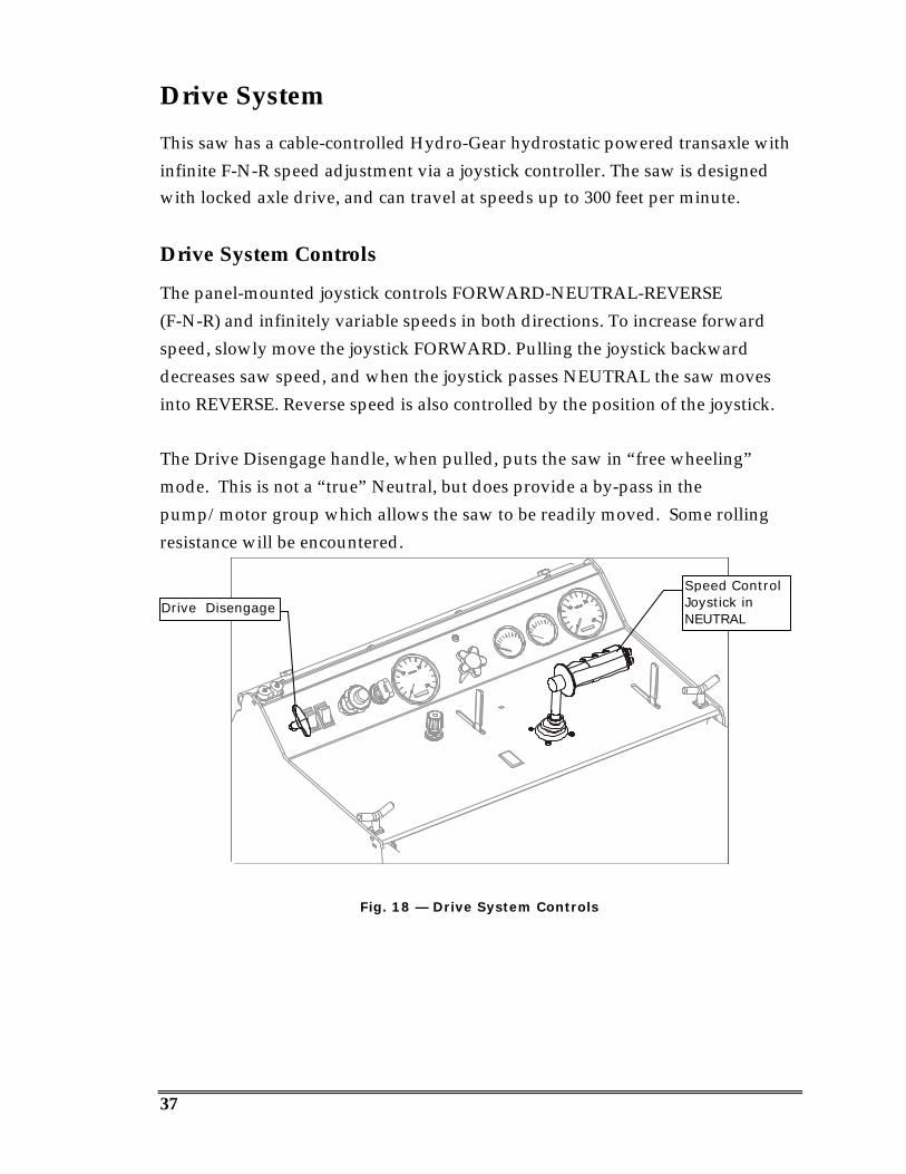
Drive System
This saw has a cable-controlled Hydro-Gear hydrostatic powered transaxle withinfinite F-N-R speed adjustment via a joystick controller. The saw is designedwith locked axle drive, and can travel at speeds up to 300 feet per minute.
Drive System Controls
The panel-mounted joystick controls FORWARD-NEUTRAL-REVERSE(F-N-R) and infinitely variable speeds in both directions. To increase forwardspeed, slowly move the joystick FORWARD. Pulling the joystick backwarddecreases saw speed, and when the joystick passes NEUTRAL the saw movesinto REVERSE. Reverse speed is also controlled by the position of the joystick.
The Drive Disengage handle, when pulled, puts the saw in “free wheeling”mode. This is not a “true” Neutral, but does provide a by-pass in thepump/motor group which allows the saw to be readily moved. Some rollingresistance will be encountered.
Fig. 18 — Drive System Controls
Speed ControlJoystick inNEUTRAL
Drive Disengage
38
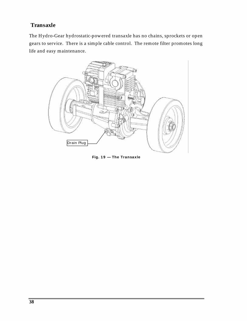
Transaxle
The Hydro-Gear hydrostatic-powered transaxle has no chains, sprockets or opengears to service. There is a simple cable control. The remote filter promotes longlife and easy maintenance.
Fig. 19 — The Transaxle
Drain Plug

39
4-Speed Blade Shaft
The exclusive 4-speed Blade Shaft allows optimum performance with a variety ofdifferent blade sizes under a wide range of conditions.
Fig. 20 — The 4-Speed Blade Shaft
The 4-speed design fully encloses the transmission, bearings and Blade Shaft,and features an oil bath lubrication (no grease fittings). Oil is cooled, filtered andcirculated, and the assembly utilizes a remote, protected fill and vent. Gearchanges are made with rack & pinion shifting. Positive shift lock prevents themulti-speed Blade Shaft from jumping out of gear. A Blade Shaft tachometerassists in gear selection.
The 4 gear ratios are:
1st Gear 1.00 : 12nd Gear 1.34 : 13rd Gear 1.70 : 14th Gear 2.02 : 1
The 1: 1 ratio is for the smallest diameter blade. The middle two ratios are forintermediate sized blades and the 2.02 : 1 ratio is for the largest blade. Bladerange is from 16” to 48”.
See page 21 or visit our web site: www.multiquip.com for additionaldiscussion of the 4-speed Blade Shaft, gears, and sheave ratios.
To calculate Blade Shaft speed, assuming a 1:1 ratio between engine and bladeshaft input, divide engine speed by the selected ratio. For example, for the 3rd
gear Blade Shaft RPM: 2500 Engine RPM ÷ 1.7 = 1470 Blade Shaft RPM in 3 rd gear.
The gear pattern is marked on the casting around the shift lever.
40
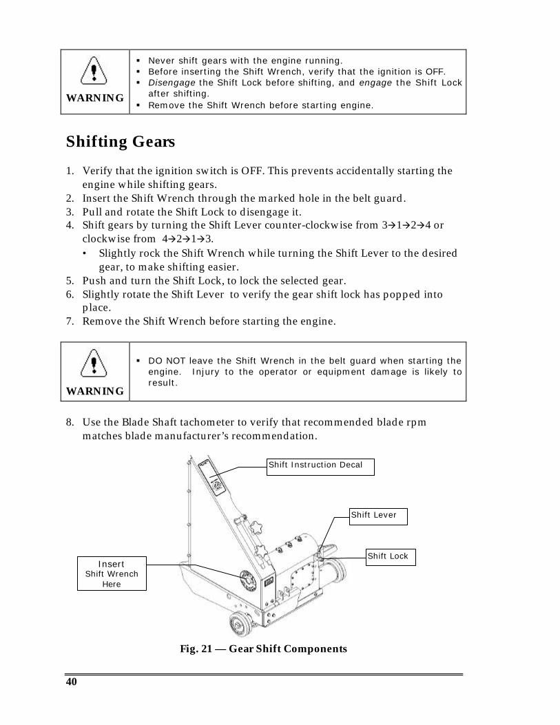
WARNING
§ Never shift gears with the engine running.§ Before inserting the Shift Wrench, verify that the ignition is OFF.§ Disengage the Shift Lock before shifting, and engage the Shift Lock
after shifting.§ Remove the Shift Wrench before starting engine.
Shifting Gears
1. Verify that the ignition switch is OFF. This prevents accidentally starting theengine while shifting gears.
2. Insert the Shift Wrench through the marked hole in the belt guard.3. Pull and rotate the Shift Lock to disengage it.4. Shift gears by turning the Shift Lever counter-clockwise from 3à1à2à4 or
clockwise from 4à2à1à3.• Slightly rock the Shift Wrench while turning the Shift Lever to the desired
gear, to make shifting easier.5. Push and turn the Shift Lock, to lock the selected gear.6. Slightly rotate the Shift Lever to verify the gear shift lock has popped into
place.7. Remove the Shift Wrench before starting the engine.
WARNING
§ DO NOT leave the Shift Wrench in the belt guard when starting theengine. Injury to the operator or equipment damage is likely toresult.
8. Use the Blade Shaft tachometer to verify that recommended blade rpmmatches blade manufacturer’s recommendation.
Fig. 21 — Gear Shift Components
Shift Instruction Decal
InsertShift Wrench
Here
Shift Lock
Shift Lever
41
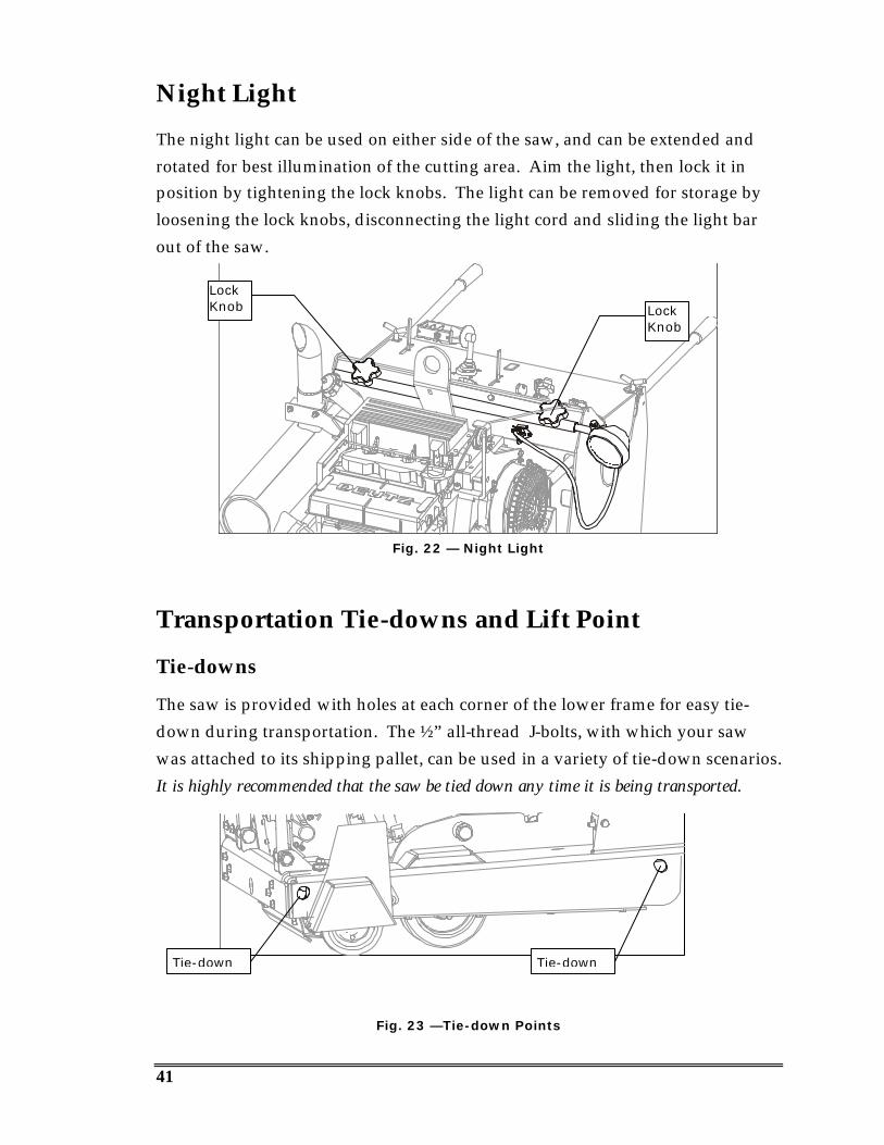
Night Light
The night light can be used on either side of the saw, and can be extended androtated for best illumination of the cutting area. Aim the light, then lock it inposition by tightening the lock knobs. The light can be removed for storage byloosening the lock knobs, disconnecting the light cord and sliding the light barout of the saw.
Fig. 22 — Night Light
Transportation Tie-downs and Lift Point
Tie-downs
The saw is provided with holes at each corner of the lower frame for easy tie-down during transportation. The ½” all-thread J-bolts, with which your sawwas attached to its shipping pallet, can be used in a variety of tie-down scenarios.It is highly recommended that the saw be tied down any time it is being transported.
Fig. 23 —Tie-down Points
LockKnob Lock
Knob
Tie-down Tie-down

42
Lift Point
The convenient single point for lifting the saw with a hoist is located just in frontof the console, between it and the engine.
Fig. 24 — Lift Point
WARNING
§ To avoid possible injury, stay clear of the saw while it is beinghoisted.
§ To avoid possible damage to the saw, use approved rigging(minimum 2000 lb. test) when hoisting the saw.
Lift Point
43
MAINTENANCE
This saw has many service-saving features, such as fully enclosed oil bathlubricated Blade Shaft bearings, which require no daily lubrication.
!NOTE
Level the saw frame surface prior to service to get accurate oil levelreadings.
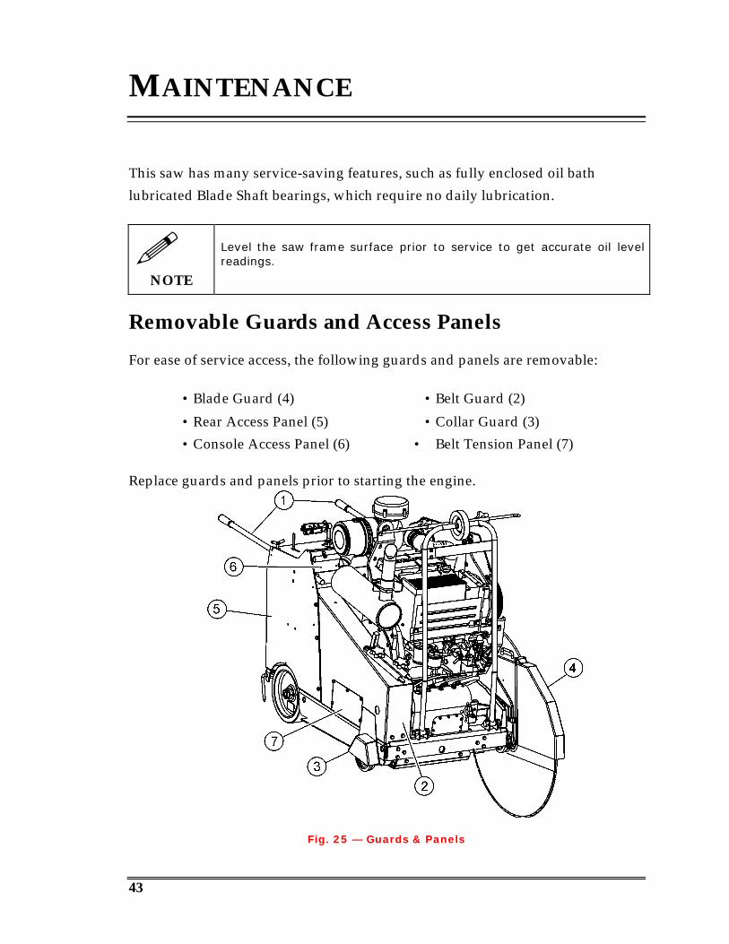
Removable Guards and Access Panels
For ease of service access, the following guards and panels are removable:
• Blade Guard (4) • Belt Guard (2)
• Rear Access Panel (5) • Collar Guard (3)• Console Access Panel (6) • Belt Tension Panel (7)
Replace guards and panels prior to starting the engine.
Fig. 25 — Guards & Panels
44
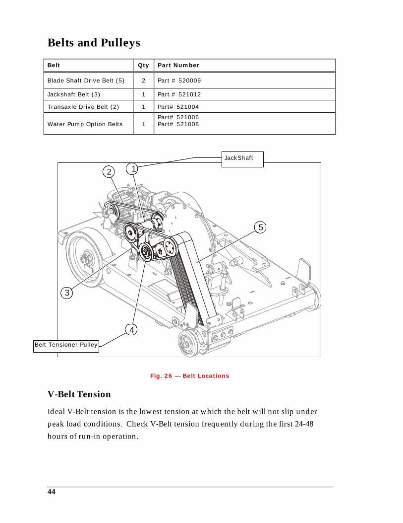
Belts and Pulleys
Belt Qty Part Number
Blade Shaft Drive Belt (5) 2 Part # 520009
Jackshaft Belt (3) 1 Part # 521012
Transaxle Drive Belt (2) 1 Part# 521004
Water Pump Option Belts 1Part# 521006Part# 521008
5
3
4
12
Fig. 26 — Belt Locations
V-Belt Tension
Ideal V-Belt tension is the lowest tension at which the belt will not slip underpeak load conditions. Check V-Belt tension frequently during the first 24-48hours of run-in operation.
Belt Tensioner Pulley
JackShaft

45
CAUTION
§ Over-tensioning shortens belt and bearing life.§ Keep belts clean of foreign material that may cause slippage.§ Make V-Belt inspection a periodic procedure.§ Never dress belts, as this can cause premature failure.
Adjusting Blade Shaft Drive Belt Tension
!NOTE
When tightening or loosening drive belts, raise the saw to reducestress on the tensioning system, and gravity will assist you by pullingthe engine backwards slightly.
1. Access the Panel on the side of the saw, loosen the Engine Mount LockBolts to allow the engine to rotate forward.
• Requires 15/16” socket, 10”- 12” extension and ratchet or breaker bar.
Fig. 27 — Engine Mount Lock Bolts
Engine MountLock Bolt
Engine MountLock Bolt
Access Panel
46
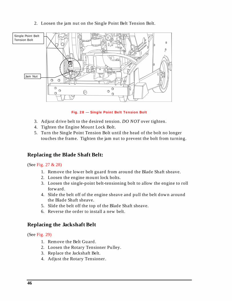
2. Loosen the jam nut on the Single Point Belt Tension Bolt.
Fig. 28 — Single Point Belt Tension Bolt
3. Adjust drive belt to the desired tension. DO NOT over tighten.4. Tighten the Engine Mount Lock Bolt.5. Turn the Single Point Tension Bolt until the head of the bolt no longer
touches the frame. Tighten the jam nut to prevent the bolt from turning.
Replacing the Blade Shaft Belt:
(See Fig. 27 & 28)1. Remove the lower belt guard from around the Blade Shaft sheave.2. Loosen the engine mount lock bolts.3. Loosen the single-point belt-tensioning bolt to allow the engine to roll
forward.4. Slide the belt off of the engine sheave and pull the belt down around
the Blade Shaft sheave.5. Slide the belt off the top of the Blade Shaft sheave.6. Reverse the order to install a new belt.
Replacing the Jackshaft Belt
(See Fig. 29)1. Remove the Belt Guard.2. Loosen the Rotary Tensioner Pulley.3. Replace the Jackshaft Belt.4. Adjust the Rotary Tensioner.
Single Point BeltTension Bolt
Jam Nut
47
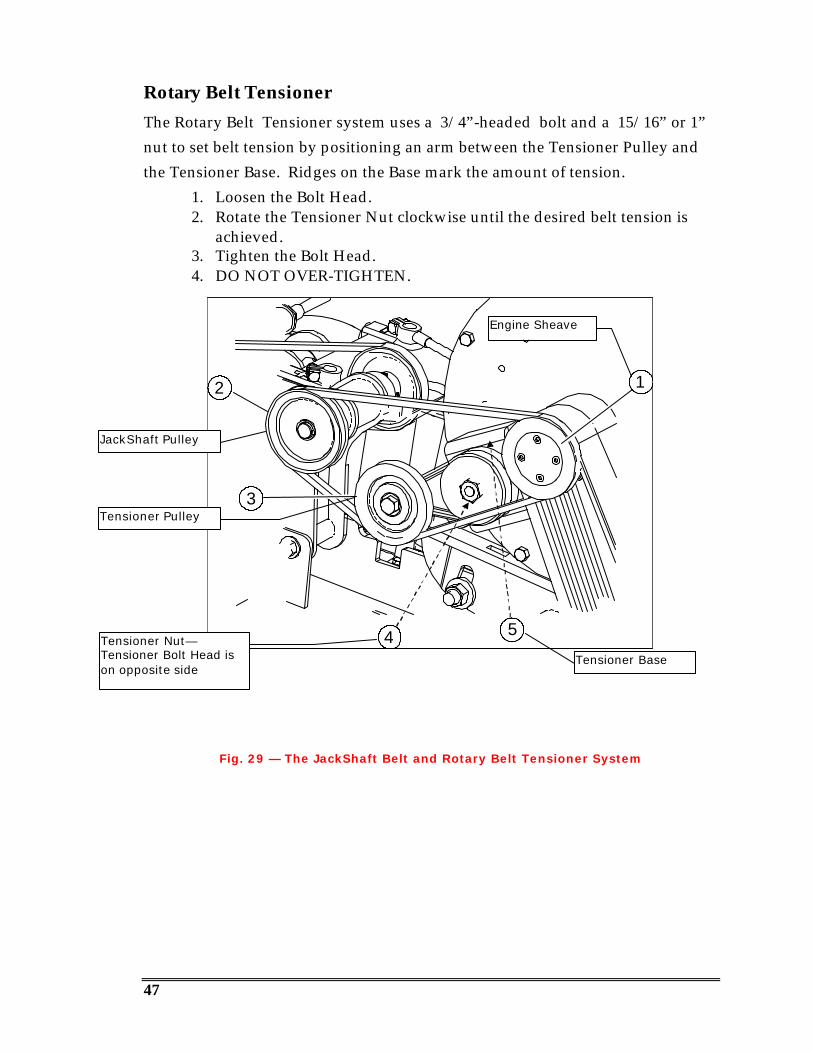
Rotary Belt TensionerThe Rotary Belt Tensioner system uses a 3/4”-headed bolt and a 15/16” or 1”nut to set belt tension by positioning an arm between the Tensioner Pulley andthe Tensioner Base. Ridges on the Base mark the amount of tension.
1. Loosen the Bolt Head.2. Rotate the Tensioner Nut clockwise until the desired belt tension is
achieved.3. Tighten the Bolt Head.4. DO NOT OVER-TIGHTEN.
12
4 5
3
Fig. 29 — The JackShaft Belt and Rotary Belt Tensioner System
Tensioner Nut—Tensioner Bolt Head ison opposite side
JackShaft Pulley
Engine Sheave
Tensioner Pulley
Tensioner Base

48
Blade Shaft Maintenance
The fully enclosed Blade Shaft eliminates most maintenance. However, shouldthe Blade Shaft need service or repair, contact Multiquip for details.
Fig. 30 — 4-Speed Blade Shaft
Blade Shaft Replacement
To assure correct Blade Shaft/Wheel alignment it is recommended that thisoperation be performed by a Multiquip Authorized Service Center.

49
Blade Collar Removal/Installation
Correct removal or installation of the Inner Blade Collar or Flange requires theCollar Puller (option Part Number 18503) shown in Figure 31.
WARNING
Follow instructions closely to prevent injury from flying Blade Collars!Because of the tapered fit between Blade Collar and Blade Shaft,5-10 tons of force is needed to release the inner collar. Parts andtools can become dangerous projectiles if instructions are notfollowed properly.
Fig. 31 — Using the Collar Puller
Removing the Inner Blade Collar
With the Outer Blade Collar in place, and the Blade Mounting Bolt loosenedapproximately ¼”:
1. While the three perimeter bolts hold the two Puller Plates together, slidethe Horseshoe Plate of the Collar Puller behind the (Shaft) side of theInner Collar as shown above.
2. Tighten the center Puller bolt to remove the Inner Collar from the BladeShaft.
• Having the Outer Collar in place prevents the Puller and Inner Collar from flyingoff when the taper breaks loose, and causing injury!
• If the Inner Collar does not readily come free from the tapered BladeShaft, lightly tap on the central Puller bolt. This should cause the collar tobreak free from the shaft.
50
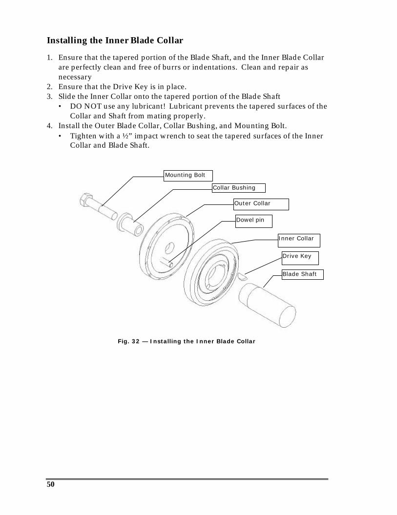
Installing the Inner Blade Collar
1. Ensure that the tapered portion of the Blade Shaft, and the Inner Blade Collarare perfectly clean and free of burrs or indentations. Clean and repair asnecessary
2. Ensure that the Drive Key is in place.3. Slide the Inner Collar onto the tapered portion of the Blade Shaft
• DO NOT use any lubricant! Lubricant prevents the tapered surfaces of theCollar and Shaft from mating properly.
4. Install the Outer Blade Collar, Collar Bushing, and Mounting Bolt.• Tighten with a ½” impact wrench to seat the tapered surfaces of the Inner
Collar and Blade Shaft.
Fig. 32 — Installing the Inner Blade Collar
Drive Key
Blade Shaft
Inner Collar
Outer Collar
Collar Bushing
Mounting Bolt
Dowel pin

51
5. Loosen the Mounting Bolt and remove the Outer Collar and Bushing.6. Inspect the Inner Collar to ensure the proper seating of the tapered fit.
• The Inner Collar should be seated between .030” and 0.0” (flush) to theend of the Blade Shaft.
Fig. 33 — Proper seating of the Inner Collar on the Blade Shaft
7. Test to ensure that the Inner Collar does not wobble when rotated. Use anindicator dial on the face of the Collar. Maximum tolerance is .003” run outon the face of the Collar.
Inner CollarBlade Shaft
52
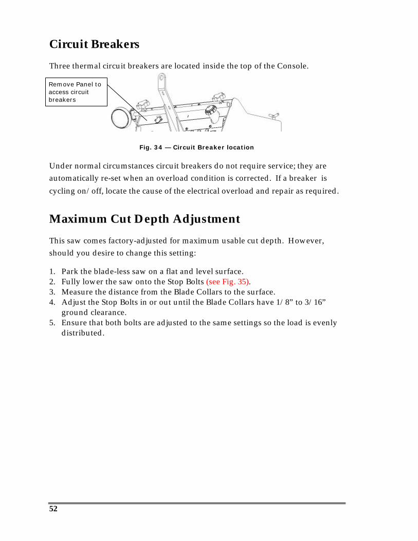
Circuit Breakers
Three thermal circuit breakers are located inside the top of the Console.
Fig. 34 — Circuit Breaker location
Under normal circumstances circuit breakers do not require service; they areautomatically re-set when an overload condition is corrected. If a breaker iscycling on/off, locate the cause of the electrical overload and repair as required.
Maximum Cut Depth Adjustment
This saw comes factory-adjusted for maximum usable cut depth. However,should you desire to change this setting:
1. Park the blade-less saw on a flat and level surface.2. Fully lower the saw onto the Stop Bolts (see Fig. 35).3. Measure the distance from the Blade Collars to the surface.4. Adjust the Stop Bolts in or out until the Blade Collars have 1/8” to 3/16”
ground clearance.5. Ensure that both bolts are adjusted to the same settings so the load is evenly
distributed.
Remove Panel toaccess circuitbreakers
53
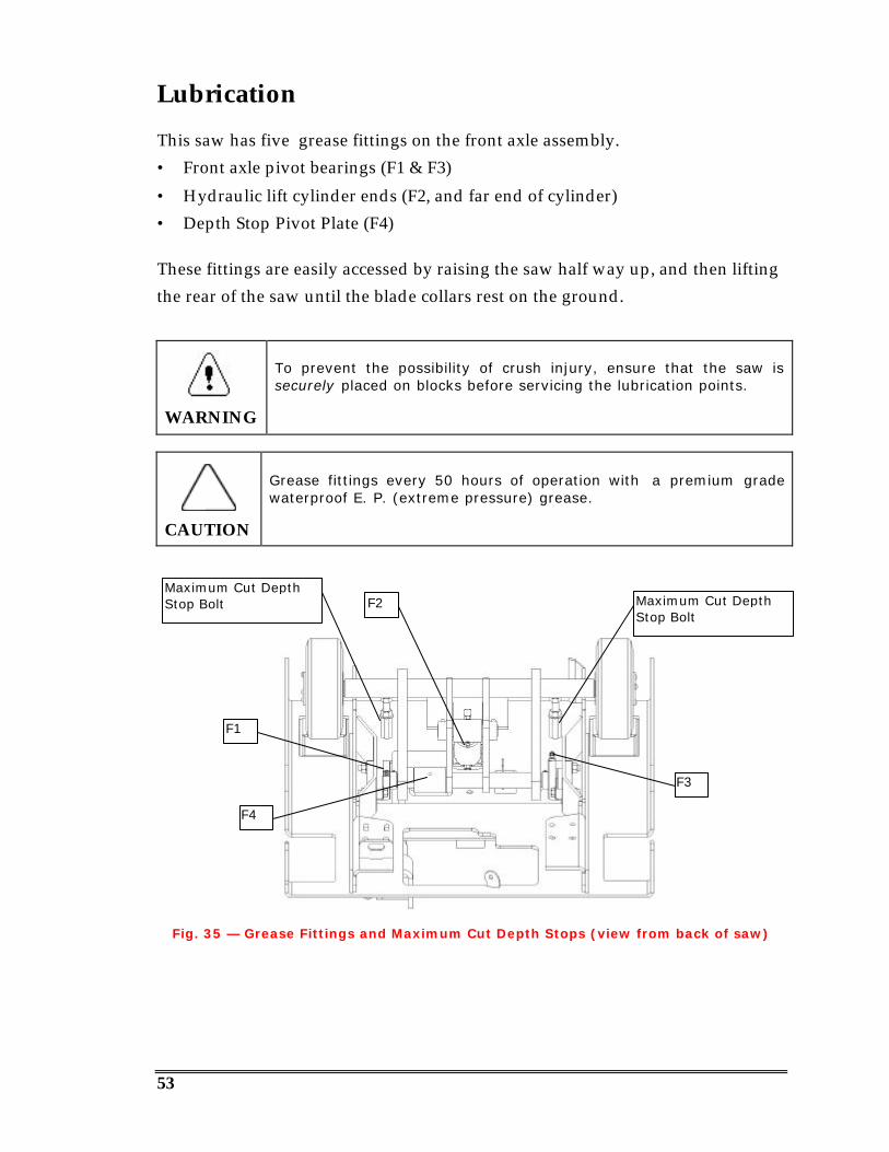
Lubrication
This saw has five grease fittings on the front axle assembly.• Front axle pivot bearings (F1 & F3)
• Hydraulic lift cylinder ends (F2, and far end of cylinder)• Depth Stop Pivot Plate (F4)
These fittings are easily accessed by raising the saw half way up, and then liftingthe rear of the saw until the blade collars rest on the ground.
WARNING
To prevent the possibility of crush injury, ensure that the saw issecurely placed on blocks before servicing the lubrication points.
CAUTION
Grease fittings every 50 hours of operation with a premium gradewaterproof E. P. (extreme pressure) grease.
Fig. 35 — Grease Fittings and Maximum Cut Depth Stops (view from back of saw)
F3
F2
F1
Maximum Cut DepthStop Bolt Maximum Cut Depth
Stop Bolt
F4
54
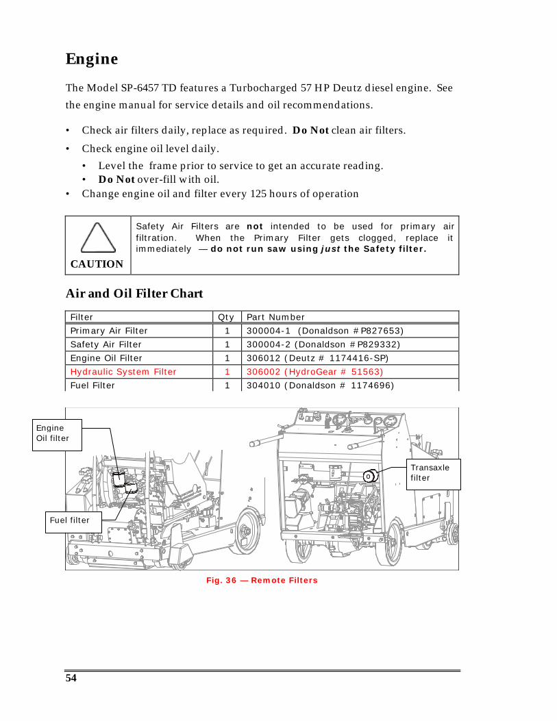
Engine
The Model SP-6457 TD features a Turbocharged 57 HP Deutz diesel engine. Seethe engine manual for service details and oil recommendations.
• Check air filters daily, replace as required. Do Not clean air filters.
• Check engine oil level daily.• Level the frame prior to service to get an accurate reading.• Do Not over-fill with oil.
• Change engine oil and filter every 125 hours of operation
CAUTION
Safety Air Filters are not intended to be used for primary airfiltration. When the Primary Filter gets clogged, replace itimmediately — do not run saw using just the Safety filter.
Air and Oil Filter Chart
Fig. 36 — Remote Filters
Filter Qty Part Number
Primary Air Filter 1 300004-1 (Donaldson #P827653)
Safety Air Filter 1 300004-2 (Donaldson #P829332)
Engine Oil Filter 1 306012 (Deutz # 1174416-SP)
Hydraulic System Filter 1 306002 (HydroGear # 51563)
Fuel Filter 1 304010 (Donaldson # 1174696)
Transaxlefilter
Fuel filter
EngineOil filter

55
PTO Drive Maintenance
Disassembly of the PTO Drive and replacement of the PTO DriveSheave/Bearing Assembly requires the PTO Bearing Puller (P/N 18610). The Sheave/Bearing Assembly is not serviceable and must bereplaced as a complete unit.1. Remove the Drive Belt (see Replacing the Blade Shaft Drive Belt).2. Remove the Drive Plate Assembly from the engine.
• The Assembly is held on by 11 bolts.• Note the clocking orientation of the plate.
3. On the workbench:• Remove the Cap Screws and End Cap (Items 1 & 2, Fig. 37).• Remove the Splined Drive Cap Screws and the Drive Cap (Items 3 & 4,
Fig. 37).• With a sharp pointed awl or similar tool, remove the flat wound spiral
retaining ring (Item #5, Fig. 37)• Attach the PTO Bearing Puller in place of the Splined Drive Cap, as shown
in Fig. 37.• Insert the Puller Alignment Bushing (1).• Attach the Puller Cap (2) with the Drive Cap Screws (3).• Thread in the PTO Bearing Puller Bolt (4).
Fig. 37 — Attaching the PTO Bearing Puller to the Drive Plate Assembly
• Tighten the Puller Bolt (4), to pull the Sheave/Bearing Assembly offof the Bearing Support (Fig. 38, #9).
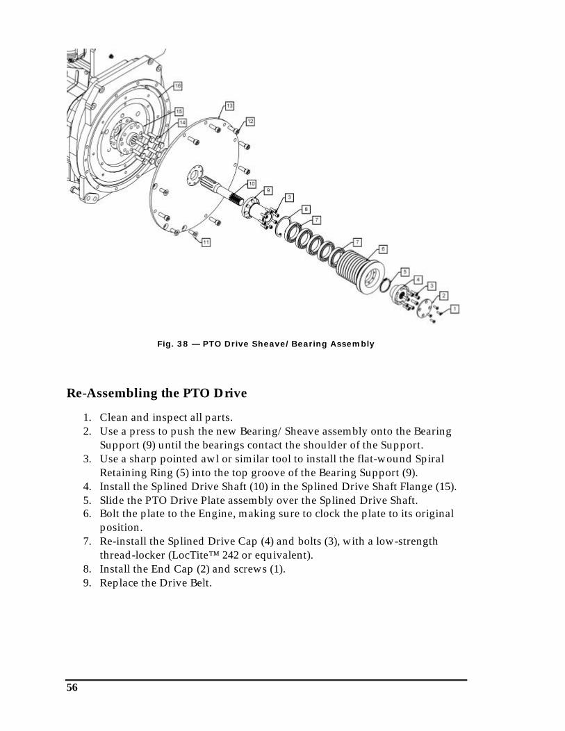
56
Fig. 38 — PTO Drive Sheave/Bearing Assembly
Re-Assembling the PTO Drive
1. Clean and inspect all parts.2. Use a press to push the new Bearing/Sheave assembly onto the Bearing
Support (9) until the bearings contact the shoulder of the Support.3. Use a sharp pointed awl or similar tool to install the flat-wound Spiral
Retaining Ring (5) into the top groove of the Bearing Support (9).4. Install the Splined Drive Shaft (10) in the Splined Drive Shaft Flange (15).5. Slide the PTO Drive Plate assembly over the Splined Drive Shaft.6. Bolt the plate to the Engine, making sure to clock the plate to its original
position.7. Re-install the Splined Drive Cap (4) and bolts (3), with a low-strength
thread-locker (LocTite™ 242 or equivalent).8. Install the End Cap (2) and screws (1).9. Replace the Drive Belt.
57
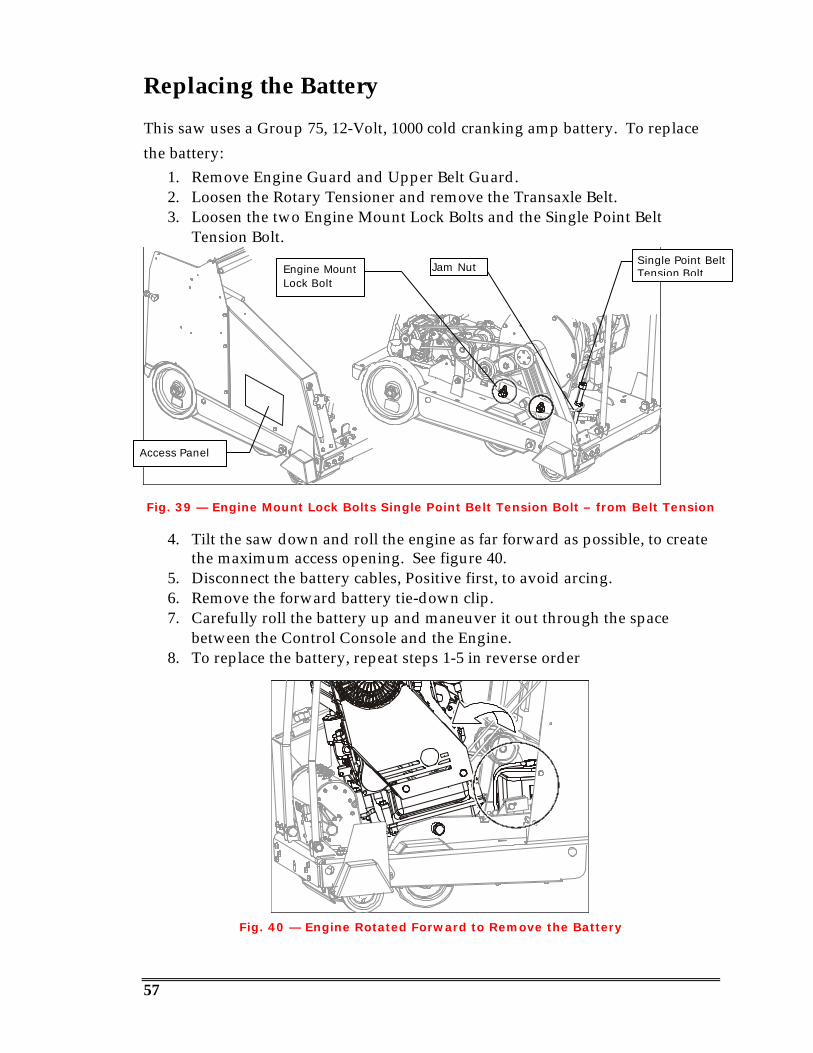
Replacing the Battery
This saw uses a Group 75, 12-Volt, 1000 cold cranking amp battery. To replacethe battery:
1. Remove Engine Guard and Upper Belt Guard.2. Loosen the Rotary Tensioner and remove the Transaxle Belt.3. Loosen the two Engine Mount Lock Bolts and the Single Point Belt
Tension Bolt.
Fig. 39 — Engine Mount Lock Bolts Single Point Belt Tension Bolt – from Belt Tension
4. Tilt the saw down and roll the engine as far forward as possible, to createthe maximum access opening. See figure 40.
5. Disconnect the battery cables, Positive first, to avoid arcing.6. Remove the forward battery tie-down clip.7. Carefully roll the battery up and maneuver it out through the space
between the Control Console and the Engine.8. To replace the battery, repeat steps 1-5 in reverse order
Fig. 40 — Engine Rotated Forward to Remove the Battery
Engine MountLock Bolt
Access Panel
Single Point BeltTension BoltJam Nut
58
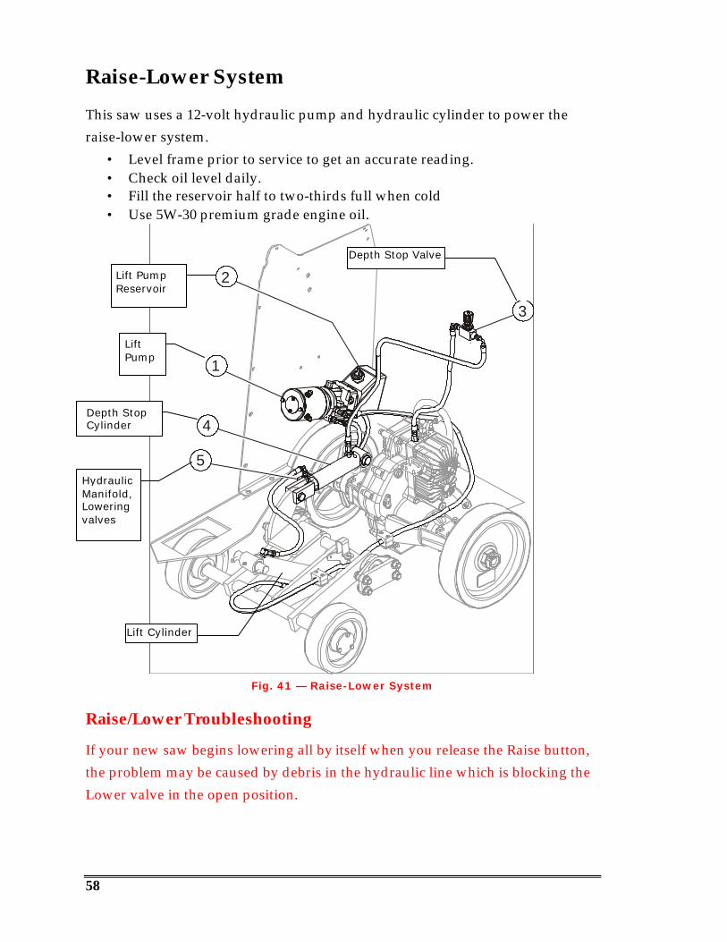
Raise-Lower System
This saw uses a 12-volt hydraulic pump and hydraulic cylinder to power theraise-lower system.
• Level frame prior to service to get an accurate reading.• Check oil level daily.• Fill the reservoir half to two-thirds full when cold• Use 5W-30 premium grade engine oil.
4
5
3
2
1
Fig. 41 — Raise-Lower System
Raise/Lower Troubleshooting
If your new saw begins lowering all by itself when you release the Raise button,the problem may be caused by debris in the hydraulic line which is blocking theLower valve in the open position.
Lift PumpReservoir
LiftPump
HydraulicManifold,Loweringvalves
Depth StopCylinder
Depth Stop Valve
Lift Cylinder

59
Joystick Tension Adjustment
The speed control joystick uses friction adjustment to provide the preferred“feel”:
1. Using a ¼” Allen wrench and 9/16” wrench, loosen both pivot bolts untilthey can be turned by hand. Pivot #1 only requires a 9/16” wrench, as theAllen nut side is welded in place.
2. Tighten pivot #1 until the handle is close to the desired “feel”.3. Tighten pivot #2 until it just starts to increase the force required to move the
handle.
Fig. 42 — Joystick Adjustment
Pivot #1
Pivot #2
60
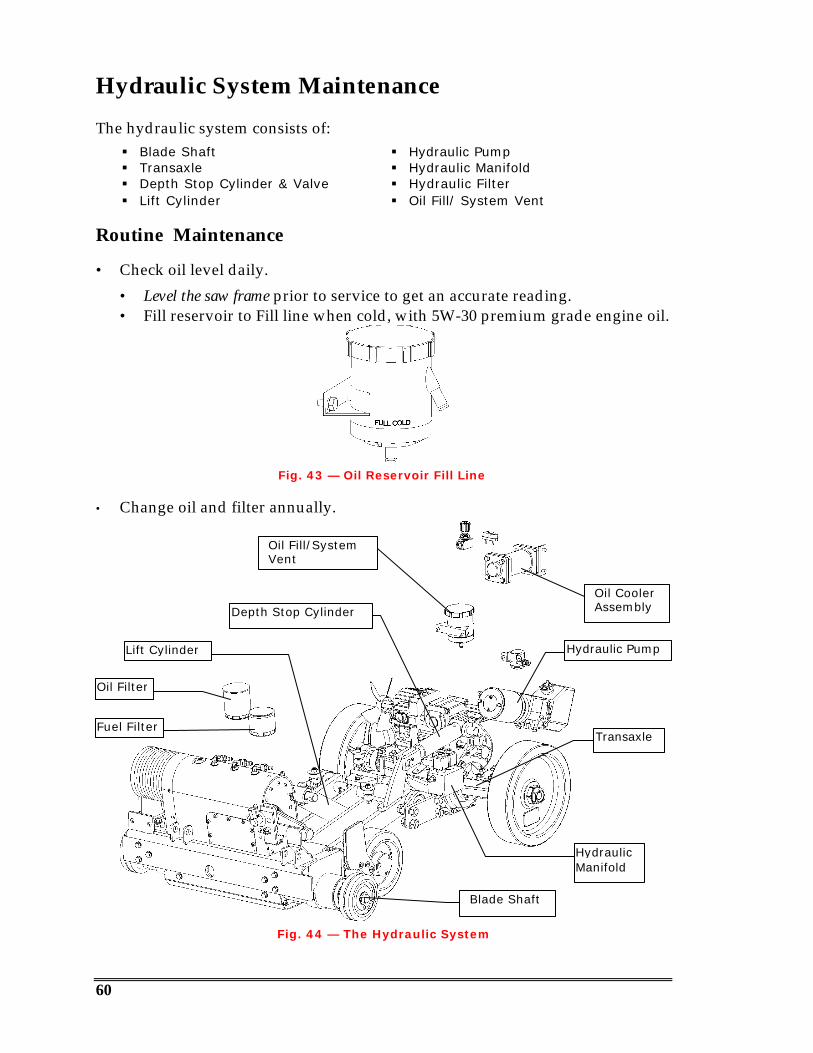
Hydraulic System Maintenance
The hydraulic system consists of:§ Blade Shaft § Hydraulic Pump§ Transaxle § Hydraulic Manifold§ Depth Stop Cylinder & Valve § Hydraulic Filter§ Lift Cylinder § Oil Fill/ System Vent
Routine Maintenance
• Check oil level daily.
• Level the saw frame prior to service to get an accurate reading.• Fill reservoir to Fill line when cold, with 5W-30 premium grade engine oil.
Fig. 43 — Oil Reservoir Fill Line
• Change oil and filter annually.
Fig. 44 — The Hydraulic System
Blade Shaft
Lift Cylinder
Depth Stop Cylinder
Oil CoolerAssembly
HydraulicManifold
Transaxle
Hydraulic Pump
Oil Fill/SystemVent
Fuel Filter
Oil Filter
61
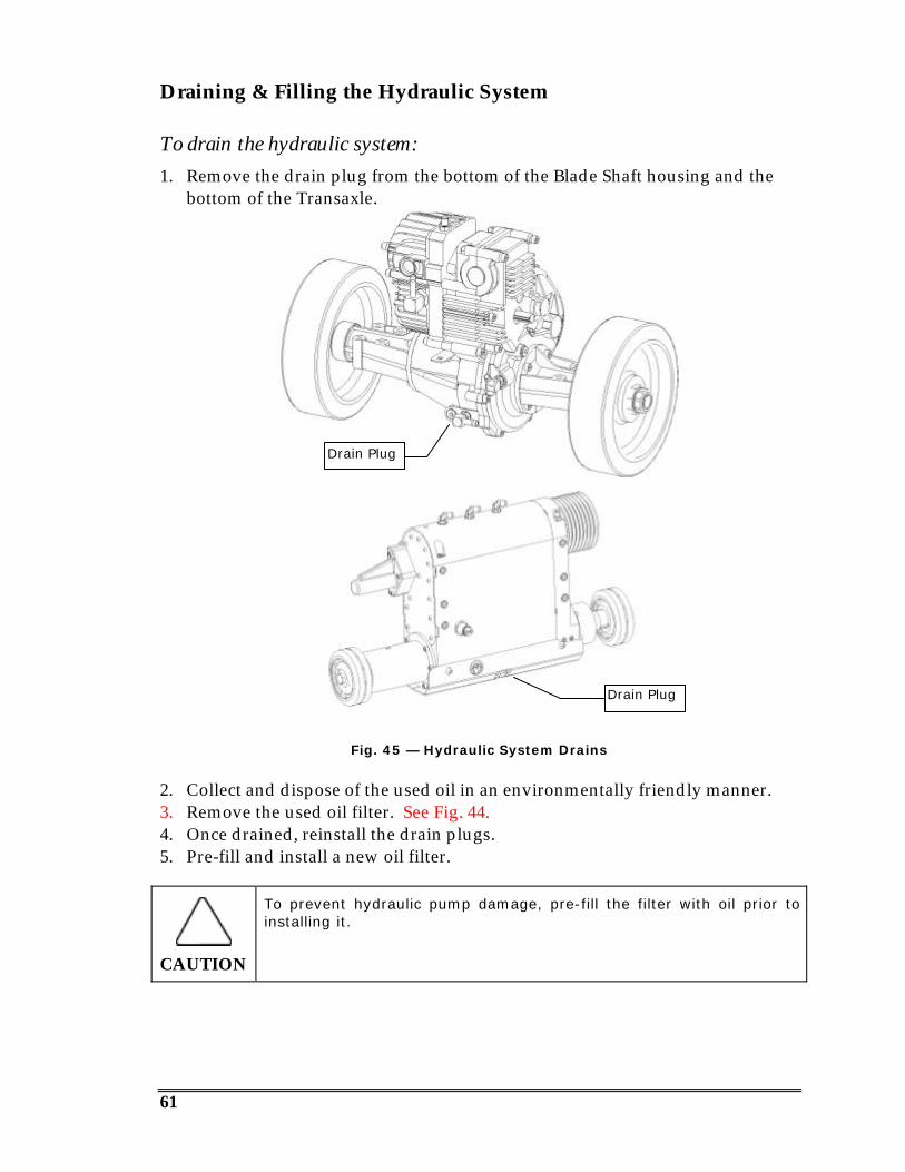
Draining & Filling the Hydraulic System
To drain the hydraulic system:1. Remove the drain plug from the bottom of the Blade Shaft housing and the
bottom of the Transaxle.
Fig. 45 — Hydraulic System Drains
2. Collect and dispose of the used oil in an environmentally friendly manner.3. Remove the used oil filter. See Fig. 44.4. Once drained, reinstall the drain plugs.5. Pre-fill and install a new oil filter.
CAUTION
To prevent hydraulic pump damage, pre-fill the filter with oil prior toinstalling it.
Drain Plug
Drain Plug
62
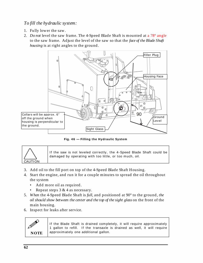
To fill the hydraulic system:1. Fully lower the saw.2. Do not level the saw frame. The 4-Speed Blade Shaft is mounted at a 78° angle
to the saw frame. Adjust the level of the saw so that the face of the Blade Shafthousing is at right angles to the ground.
Fig. 45 — Adjusting the level of the Blade Shaft
Fig. 46 — Filling the Hydraulic System
CAUTION
If the saw is not leveled correctly, the 4-Speed Blade Shaft could bedamaged by operating with too little, or too much, oil.
3. Add oil to the fill port on top of the 4-Speed Blade Shaft Housing.4. Start the engine, and run it for a couple minutes to spread the oil throughout
the system• Add more oil as required.• Repeat steps 3 & 4 as necessary.
5. When the 4-Speed Blade Shaft is full, and positioned at 90° to the ground, theoil should show between the center and the top of the sight glass on the front of themain housing.
6. Inspect for leaks after service.
!NOTE
If the Blade Shaft is drained completely, it will require approximately1 gallon to refill. If the transaxle is drained as well, it will requireapproximately one additional gallon.
90
Filler Plug
Sight Glass
Collars will be approx. 6”off the ground whenhousing is perpendicular tothe ground.
Housing Face
GroundLevel
63
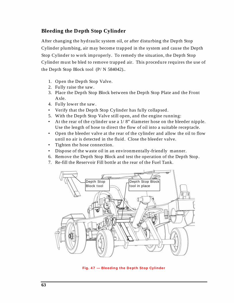
Bleeding the Depth Stop Cylinder
After changing the hydraulic system oil, or after disturbing the Depth StopCylinder plumbing, air may become trapped in the system and cause the DepthStop Cylinder to work improperly. To remedy the situation, the Depth StopCylinder must be bled to remove trapped air. This procedure requires the use ofthe Depth Stop Block tool (P/N 584042)..
1. Open the Depth Stop Valve.2. Fully raise the saw.3. Place the Depth Stop Block between the Depth Stop Plate and the Front
Axle.4. Fully lower the saw.• Verify that the Depth Stop Cylinder has fully collapsed.5. With the Depth Stop Valve still open, and the engine running:• At the rear of the cylinder use a 1/8” diameter hose on the bleeder nipple.
Use the length of hose to direct the flow of oil into a suitable receptacle.• Open the bleeder valve at the rear of the cylinder and allow the oil to flow
until no air is detected in the fluid. Close the bleeder valve.• Tighten the hose connection.• Dispose of the waste oil in an environmentally-friendly manner.6. Remove the Depth Stop Block and test the operation of the Depth Stop.7. Re-fill the Reservoir Fill bottle at the rear of the Fuel Tank.
Fig. 47 — Bleeding the Depth Stop Cylinder
Depth StopBlock tool
Depth Stop Blocktool in place

64
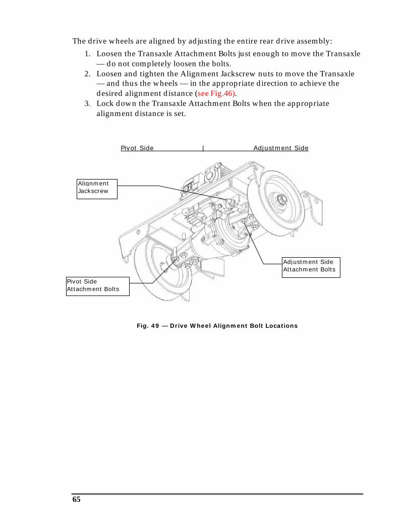
Drive Wheel Alignment
Below is the technique recommended for aligning the wheels. Distance X is thesame on both sides; the Front Wheel and Blade shaft axles must be at right anglesto the frame edge. Distance A is 3/16” (.187”) longer on the right side, so that thesaw steers slightly left. Users may wish to alter the alignment to fit a particularapplication.
Fig. 48 — Drive Wheel Alignment
Distance X
Distance X
Distance A
Distance = A + .187”
65
The drive wheels are aligned by adjusting the entire rear drive assembly:1. Loosen the Transaxle Attachment Bolts just enough to move the Transaxle
— do not completely loosen the bolts.2. Loosen and tighten the Alignment Jackscrew nuts to move the Transaxle
— and thus the wheels — in the appropriate direction to achieve thedesired alignment distance (see Fig.46).
3. Lock down the Transaxle Attachment Bolts when the appropriatealignment distance is set.
Pivot Side | Adjustment Side
Fig. 49 — Drive Wheel Alignment Bolt Locations
Adjustment SideAttachment Bolts
Pivot SideAttachment Bolts
AlignmentJackscrew

66
SPECIFICATIONS
Engine 57 HP Turbocharged Deutz Diesel, direct injection, air/oil cooling, oil filter andabove-frame remote oil drain.
Engine Air Cleaner 4-Stage air filtration, pre-cleaner plus cartridge element and safety element.
Fuel Tank 10 Gallon clear-molded plastic fuel tank with sight gauge, central drain andshutoff valve.
Blade Shaft Assembly
Fully enclosed transmission, bearings and shaft, oil bath lubrication with cooledand filtered oil circulation system, 4 protected shaft seals, 2-3/8” diameter bladeshaft, rack & pinion shifting, positive shift lock, oil sight gauge, magnetic drainplug, easy serviceability, remote protected oil fill and vent, blade usable on eitherside of saw, taper lock blade collar attachment, standard blade shaft tachometer,ratios of 1:1, 1.34:1, 1.7:1, and 2.02:1
Blade Collars Plated quick-disconnect, taper lock attachment, 5.5” diam., 24 water spray ports.
Blade Flushing Minimum water usage system, evenly distributed across the blade, panel-mounted flow control.
Blade Range 14” to 48”.Max Cut Depth 21”.
Blade Guard Extra heavy design, slip-on type with double lip seal and quick disconnect waterhose, two handles.
Blade Shaft Drive Belt Dual 5--Groove premium quality Goodyear HY-T Wedge Torque Team belts.
Blade Control 12-Volt hydraulic raise/lower system, 3 blade plunge speeds, fast and slow bladeplunge speed buttons on joystick, raise button on joystick, one-hand control.
Blade Depth Stop Positive, heavy-duty hydraulically controlled depth stop.Balance Front steer.Handlebars 3-Position adjustable angle, storage position, quick locks.
Front Wheels 8” x 3”, precision sealed bearings in each wheel with extra end seals and sealprotectors, no grease points.
Rear Wheels 12” x 3”.
Drive System Hydrostatic powered transaxle with infinite speed control, joystick control, remoteoil filter and up to 300 feet per minute travel speed. Locked axle drive.
Engine Controls Twist-lock throttle, backlit tachometer with hour meter, voltmeter, oil pressuregauge and 3-position ignition switch.
Battery 12-Volt, group 75, 1000 cold cranking amps.Front Pointer Heavy gauge steel, 6” pointer wheel and plastic-coated tether.Rear Pointer Standard, adjustable.Hardware Grade 8 fasteners throughout.Tools 15/16” Blade wrench.
Dimensions L= 47-1/2” with handlebars stored, W = 32” w/o blade collars, H= 44” with frontpointer up.
Weight 1,700 Pounds, with oil but no fuel.
Serviceability Spin-on oil filters, lubrication points, lube every 50 hours.
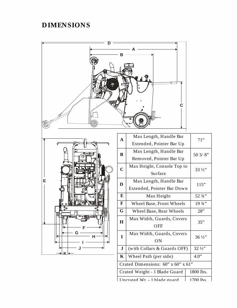
DIMENSIONS
AD
B
C
E
FG
HI
JK
AMax Length, Handle BarExtended, Pointer Bar Up
71”
BMax Length, Handle BarRemoved, Pointer Bar Up
50 3/8”
CMax Height, Console Top to
Surface33 ½”
DMax Length, Handle Bar
Extended, Pointer Bar Down115”
E Max Height 52 ¾”F Wheel Base, Front Wheels 19 ¾”G Wheel Base, Rear Wheels 28”
HMax Width, Guards, Covers
OFF35”
IMax Width, Guards, Covers
ON36 ½”
J (with Collars & Guards OFF) 32 ½”
K Wheel Path (per side) 4.0”
Crated Dimensions: 60” x 60” x 61”
Crated Weight - 1 Blade Guard 1800 lbs.
Uncrated Wt. - 1 blade guard 1700 lbs.
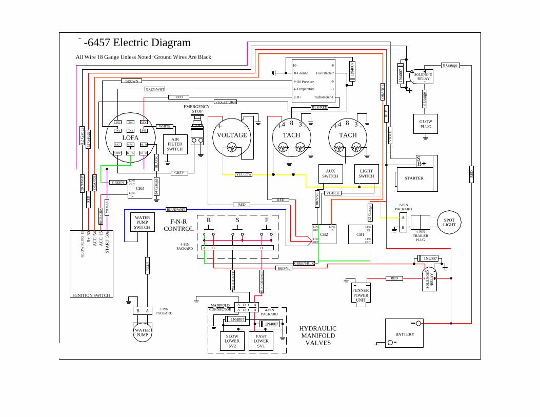
Q-6457 Electric DiagramAll Wire 18 Gauge Unless Noted: Ground Wires Are Black
BATTERY
F-N-RCONTROL
SOL
EN
OID
/RE
LA
Y
FENNER POWER
UNIT
TACHVOLTAGE
34 8 -- ++
FSR
HYDRAULIC MANIFOLD
VALVES
WATER PUMP FAST
LOWERSV1
SLOW LOWER
SV2
WATER PUMP
SWITCH
B
CB1CB2
LIGHTSWITCH
AUXSWITCH
BB
LINEOUT
LINEOUT
LINEIN
+
LINEIN 4- PIN
TRAILER PLUG
SPOT LIGHT
LINEOUT
A BD CA BCD
A B C D
2-PINPACKARD
4-PINPACKARD
4-PINPACKARD
MANIFOLDCONNECTOR
A
B
AB 2-PINPACKARD
+
IN2 IN4 GEN
IN3IN1 IN5
+
SOLENOID/RELAY-
IGNITION SWITCH
GL
OW
PL
UG
19
B+
30
AC
C 5
4A
CC
15
STA
RT
50a
LOFA
STARTER
BS
GLOW PLUG
2-D+
4-Temperature
6-
8-Ground
10-
Tachometer-1
-3
-5
Fuel Rack-7
-9
KL 31
KL 50
MAG
KL 15
SIG
STOP
622500- Q-6457 Electrical 08-15-01
EMERGENCYSTOP
AIRFILTERSWITCH
1N4007
1N40
07
1N4007
1N4007
1N40
07
Oil Pressure
LINEIN
CB3
LINEOUT
12 G
auge
12 G
auge
8 G
auge
8 Gauge
12 G
auge
14 G
auge
OR
N/W
HT
RED
OR
AN
GE
RE
D/G
RN
VIO
LET
BLUE/WHT
BL
UE
GREY/WHT
REDVIOLET/ORN
BROWN
WHITE
GREY
BL
AC
K
GREEN
YELLOW
REDRED
BR
N/Y
L YL/BLK
BLK/RED
RE
D
WH
ITE
/RE
D
BLK
/OR
AN
GE
RED/YLGREEN/BLK
RED
OR
AN
GE
RE
DV
IOL
ET
B B
TACH+4 8 3 -

MULTIQUIP INC.POST OFFICE BOX 6254CARSON, CA 90749310-537-3700 • 800-421-1244FAX: 310-537-3927E-MAIL: [email protected]
www: multiquip.comAtlanta • Boise • Dallas • Houston • Newark
Quebec, Canada • Manchester, UK • Rio De Janiero, BR •