Embed Size (px)
Citation preview
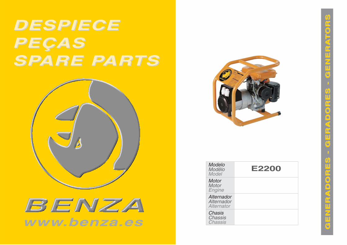
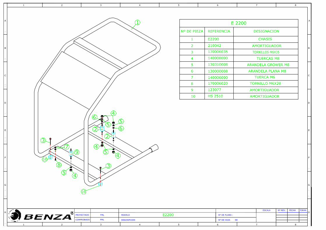
DESPIECEDESPIECEPEÇASPEÇASSPSPARE PARE PARARTSTS
www.benza.es
E2200Modelo
Motor
Alternador
Chasis
Modêlo
Motor
Alternador
Chassis
Model
Engine
Alternator
Chassis
GE
NE
RA
DO
RE
S -
GE
RA
DO
RE
S -
GE
NE
RA
GE
NE
RA
DO
RE
S -
GE
RA
DO
RE
S -
GE
NE
RA
TTO
RS
OR
S
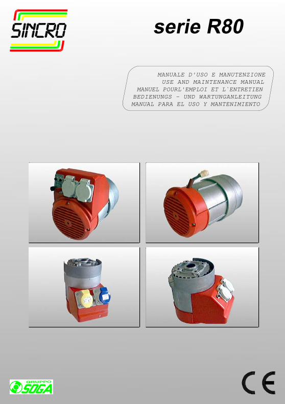
MANUALE D'USO E MANUTENZIONEUSE AND MAINTENANCE MANUAL
MANUEL POURL'EMPLOI ET L`ENTRETIENBEDIENUNGS - UND WARTUNGANLEITUNGMANUAL PARA EL USO Y MANTENIMIENTO
serie R80
INFORMAZIONI GENERALI
Le presenti istruzioni hanno lo scopo d’indi-care le corrette condizioni d’impiego e ma-nutenzione dei generatori SINCRO.
VERIFICHE PRELIMINARISi raccomanda di esaminare l’alternatoreper verificare che non abbia subito dannidurante il trasporto.
IMMAGAZZINAGGIOIn caso di inutilizzo prolungato, l’alternatoredeve essere immagazzinato in luogo asciuttoe coperto.Prima della messa in servizio, dopo lunghiperiodi di inattività, controllare la bontà d’iso-lamento di tutti gli avvolgimenti; valori ac-cettabili devono essere maggiori di 2 MΩ.In caso contrario si deve procedereall’essiccazione del solo alternatore in for-no (60÷80°C).
INSTALLAZIONEPrima della messa in funzione, verificare labontà dei collegamenti, e l’assenza d’impe-dimenti alla rotazione del rotore.Fare attenzione che le aperture per l’aspira-zione e espulsione dell’aria non siano ostru-ite, evitare inoltre che l’alternatore aspiril’aria calda espulsa dall’alternatore stessoe/o dal motore.
COLLEGAMENTO ELETTRICORispettare le norme di sicurezza vigenti delpaese d’utilizzo.Verificare che i dati di targa siano conformialle caratteristiche dell’impianto a cui lamacchina verrà collegata.Provvedere al collegamento a terra del grup-po.
MANUTENZIONEVerificare che non ci siano anomalie, comevibrazioni - rumori - uscite d’aria ostruite.
ATTENZIONE!Non toccare l'alternatore durante il funzio-namento e subito dopo l'arresto del gruppo,in quanto vi potrebbero essere superfici atemperatura elevata
Le macchine elettriche rotanti sono macchi-ne che presentano parti pericolose in quan-to poste sotto tensione o dotate di movi-mento durante il funzionamento, pertanto:- un uso improprio- la rimozione delle protezioni e lo scollega-mento dei dispositivi di protezione- la carenza di ispezioni e manutenzionepossono causare gravi danni a persone ocose.Di conseguenza per ogni operazione dicarattere elettrico o meccanico si richiedepersonale qualificato.
GENERAL INFORMATION
The object of these instructions is to indica-te correct operating - maintenanceconditions.
PRELIMINARY CHECKSWe recommend inspecting the alternatorafter shipping for damage.
STORAGEIn case the alternator is not installedimmediately, it should be kept indoors in adry place.Before starting the alternator, after a longperiod of inactivity or storage, the insulationresistance of the winding must be measured.An acceptable value is at least 2 MΩ.If this is not reached, only the alternatormust be dried in an oven at 60 ÷ 80 C°.
INSTALLATIONBefore starting we recommended checkingthe connections and make sure that there isno obstacle to the rotation of the rotor.Make sure that the air inlet and outlet arefree from obstacles.Prevent the alternator from sucking thewarm air from the motor or itself.
ELECTRIC CONNECTIONThe electric connection must be performedin accordance with the local regulations inforce. Make sure that the rating plate datacorrespond to the specifications of the powermains to which the machine will beconnected. Provide the unit with adequategrounding.
MAINTENANCECheck periodically if there are any anomaliessuch as vibrations - noise - obstructions ofinlets and outlets.
WARNING!Never touch the alternator during operationor immediately after the stopping of the unitbecause some surface parts might still bevery hot.
Electric rotating machines have dangerousparts: when operating they have live androtating components. Therefore:- improper use- the removal of protective covers and thedisconnection of protection devices- inadequate inspection and maintenancecan cause personal injury or propertydamage.Electrical and mechanical servicing mustbe performed by qualified personnel only.
INFORMATIONS GENERALES
Le présent mode d’emploi a pour objet dedonner les informations nécessaires à unemploi et à un entretien correct desgénérateurs SINCRO.
VERIFICATIONS PRELIMINAIRESContrôler l’état de l’alternateur afin de releverles dommages éventuels subis durant letransport.
STOCKAGEEn cas de non-utilisation prolongée del’alternateur, ce dernier doit être stockédans un lieu sec et à l’abri des agentsatmosphériques. Après une période denon-utilisation prolongée, la mise en servicedoit être précédée par un contrôle del’isolement de tous les enroulements. Lesvaleurs acceptables doivent être supérieuresà 2MΩ. Si tel n’est pas le cas, procéder à ladessiccation de l’alternateur dans un four(60÷80°C).
INSTALLATIONAvant la mise en service, vérifier la qualitédes connexions et qu’il n’existe aucunempêchement à la rotation du rotor.S’assurer que les ouvertures pour laventilation ne sont pas obstruées. Eviterque l’alternateur aspire ses propresémanations d’air chaud ou celles émisespar le moteur.
CONNEXION ELECTRIQUERespecter les normes de sécurité en vigueurdans le pays d’installation. Vérifier laconformité des données de plaque auxcaractéristiques de l’installation à laquellela machine sera branchée. Effectuer laliaison du groupe avec la borne de terre.
ENTRETIENVérifier périodiquement le bon fonction-nement du groupe afin de releverd’éventuelles anomalies comme, vibrations- bruits suspects - obstruction des sortiesd’air.
ATTENTION!Ne pas toucher l’alternateur lors de sonfonctionnement et tout de suite après l’arrêtdu groupe à cause d’un risque detempérature élevée des surfaces.
Les machines électriques rotativesprésentent des parties dangereuses carelles sont sous tension ou dotées demouvement. C’est pourquoi:-Une utilisation non conforme,-La violation des protections et ledébranchement de ces dernières,-Un manquement dans les contrôles etl’entretien,peuvent causer de graves dommages auxpersonnes et aux matériels.Toutes les opérations à caractère électriqueou mécanique demandent donc l’interventionde personnel qualifié.
! !!
INFORMACIONES GENERALES
Este manual ha sido recopilado con elobjetivo de suministrar al usuario todas lasindicaciones necesarias sobre el correctoempleo y mantenimiento de los alternadoresSINCRO.
VERIFICACIÓN PRELIMINÁRAconsejamos comprobar que el alternadorno haya sufrido daños durante el transporte.
ALMACENAJEEn caso de largos períodos de inactividad,hay que almacenar el alternador en un lugarseco y cubierto.Antes de la puesta en marcha, después deun período largo de inactividad, controlar elaislamiento de todos los bobinados, valoresaceptables tienen que ser mayores de los2MΩ. En caso contrario hay que secar sóloel alternador en horno (60÷80°C).
INSTALACIÒNAntes de la puesta en marcha verificar elestado de las conexiones y comprobar queno hay nada que pueda impedir la rotaciòndel rotor.Controlàr que los orifìcios de aspiración-expulsión del aire no están obstruidos,además evitar que el alternador aspire airecaliente evacuado por el mismo alternadory/o por el motor.
CONEXIÓN ELÉCTRICARespetar las normas de seguridad vigentesen el país de utilización.Verificar que los datos de placacorresponden a las características de la reden el lugar de instalación de la máquina.Efectuar la puesta a tierra del grupo.
MANTENIMIENTOComprobar que no hay anomalías comovibraciones, ruidos y salidas de aireobstruidas.
ATENCIÓNNunca tocar el alternador durante elfuncionamiento o inmediatamente despuésde la parada del grupo, dado que haysuperficies de temperatura elevadaLas màquinas eléctricas giratorias sonmáquinas que tienen piezas peligrosas yaque están bajo tensión o se mueven duranteel funcionamiento. Por lo tanto:- el uso inadecuado- la remoción de las protecciones y ladesconexión de los dispositivos deseguridad- la falta de chequeo y mantenimiento,pueden causar danõs graves a personas ocosas.Por consiguiente, las operaciones decarácter eléctrico o mecánico deben llevarsea cabo únicamente por personascualificadas.
ALLGEMEINE INFORMATIONEN
Diese Anleitung dient zur richtigenVerwendung und Wartung der SINCROGeneratoren.
VORPRÜFUNGEs wird empfohlen, sich zu überzeugen,daß der Generator keinen Versandschadenerlitten hat.
LAGERUNGWenn man für eine lange Zeit den Generatornicht verwendet, soll er auf einer trockenenStelle gelagert werden. Vor derInbertriebsetzung ist es besser, dieIsolierung aller Wicklungen zu prüfen; nurein über 2 MΩ liegender Wert ist akzeptabel,sonst ist das Trocknen des Generators imOfen (60÷80°C) erforderlich.
INSTALLATIONVor der Inbetriebnahme, sind die Anschlüsseauf ihre guten Zustand zu prüfen, der Rotorsoll hindernisfrei rotieren können. Sichüberzeugen, daß die Öffnungen für dieLuftanssaugung und den Luftauslaß nichtverstopft sind.Es ist zu vermeiden, daß derWechselstromgenerator die vom Generatorselbst bzw. vom Motor ausgestoßeneWarmluft ansaugt.
ANSCHLUSSFür den Anschluß die landesgültigenUnfallschutzvorschriften einhalten.Sich überzeugen, daß die Daten desSchildes den Eigenschaften der Anlageentsprechen, an die die Maschineangeschlossen wird.Für den Erdungsanschluß des Aggregatsvorsehen.
WARTUNGEs ist wichtig, daß keine Schwingungen,Geräusche, verstopfte Luftauslässevorhanden sind.
ACHTUNGDen Generator während des Betriebs undgleich nach dem Anhalten des Aggregatsnicht anfassen, da die Flächen heiß seinkönnten.Elektrische Rotationmaschinen weisengefährliche Teile auf, die entweder unterSpannung stehen oder während desMaschinenbetriebs drehen.Daher können:- unsachgemäßer Gebrauch;- Entfernen der Schutzverkleidungen undÜberbrücken oder Abklemmen derSchutzeinrichtungen- mangelhafte Inspektion oder Wartungzu schweren Personen- oder Sachschädenführen.Daher soll jeder elektrische odermechanische Eingriff von Fachpersonalvorgenommen werden.
!!
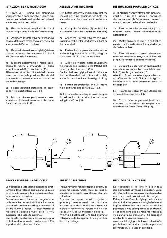
ISTRUZIONI PER IL MONTAGGIO
ATTENZIONE: prima del montaggioverificare che le sedi coniche di accoppia-mento (sia dell'alternatore che del motore)siano regolari e ben pulite.
1) Fissare lo scudo copriventola (1) almotore (dopo averlo tolto dall'alternatore).
2) Applicare il tirante (15) per il fissaggioassiale del rotore avvitandolo a fondo sullasporgenza dell'albero motore.
3) Fissare l'alternatore completo (statoree rotore assieme) allo scudo con i 4 tirantiM5 (10) con relative rosette.
4) Bloccare assialmente il rotore appli-cando la rosetta e avvitando il dadoautobloccante M8 (D) sul tirante (15).Attenzione: prima di applicare il dado osser-vare che parte della porzione filettata deltirante entri nel rotore permettendo cosí unsicuro bloccaggio.
5) Fissare la cuffia di protezione (11) usan-do le 4 viti autofilettanti 3.9 x 9.5.
6) Nel caso di accoppiamento orizzonta-le sostenere l'alternatore con un antivibrantefissato sul dado M8 (13).
ASSEMBLY INSTRUCTIONS
ON: before assembly make sure that theconical coupling housings for both thealternator and the motor are in order andclean.
1) Clamp the fan shield (1) on the drivemotor (after removing it from the alternator).
2) Apply the tie rod (15) for the axialclamping of the rotor, and screw it tight onthe drive shaft.
3) Fasten the complete alternator (statorand rotor together) to its shield, using the4 tie rods M5 (10) and the washers.
4) Axially lock the rotor in place by applyingthe washer and tightening the M8 (D) self-locking nut on the tie rod (15).Caution: before applying the nut, make surethat the threaded part of the rod partiallyenters the rotor in order to obtain tight locking.
5) Fasten the protection grid (11) usingthe 4 self threading screws 3.9 x 9.5.
6) If a horizontal coupling is used, supportthe alternator with a vibration dampenerusing the M8 nut (13).
INSTRUCTIONS POUR LE MONTAGE
ATTENTION: Avant d’effectuer le montage,vérifier que les sièges coniquesd’accouplement (de l’alternateur comme dumoteur) sont en ordre et bien nettoyés.
1) Fixer le bouclier couvre-rotor (1) aumoteur (après l’avoir désolidarisé del’alternateur).
2) Mettre en place la tige (15) de fixationaxiale du rotor en le vissant à fond à l’ergotde l’arbre moteur.
3) Fixer l’alternateur (complet de stator etrotor) au bouclier au moyen de 4 tiges M5(10) avec rondelles correspondantes.
4) Bloquer l’axe du rotor en appliquant larondelle et en serrant l’écrou autobloquantM8 (D) sur la tige centrale (15).Attention: Avant de mettre en place l’écrou,contrôler que la partie filetée de la tige estinsérée dans le rotor permettant ainsi unblocage sûr.
5) Fixer le protecteur (11) en utilisant les4 vis autoforeuses 3.9 x 9.5.
6) En cas d’accouplement horizontal,soutenir l’alternateur au moyen d’unantivibratoire fixé à l’écrou M8 (13).
REGOLAZIONE DELLA VELOCITA'
La frequenza e la tensione dipendono diret-tamente dalla velocità di rotazione, la qualedeve quindi rimanere il più possibile costan-te al variare del carico.Considerando che il sistema di regolazionedella velocità dei motori di trascinamentopresenta in generale una leggera caduta digiri tra vuoto e carico, si raccomanda diregolare la velocità a vuoto circa il 3÷4%superiore alla velocità nominale.Con questa regolazione la tensione erogatadall'alternatore a vuoto risulta circa il 5%superiore del valore nominale.
SPEED ADJUSTMENT
Frequency and voltage depend directly onrotational speed, which must be kept asconstant as possible regardless of changesin the load.Drive-motor speed control systemsgenerally have a small drop in speedbetween no load and loaded conditions. Wetherefore recommend setting the no-loadspeed 3÷4% above the nominal speed.With this adjustment the no load alternatorvoltage should be approx. 5% higher thanthe rated voltage.
REGLAGE DE LA VITESSE
La fréquence et la tension dépendentdirectement de la vitesse de rotation. Cettedernière doit rester la plus constante possiblemême en cas de variation de la charge.Puisque le système de réglage de la vitessedes entraîneurs présente en générale unelégère diminution des tours entre lespassages à vide et les passages en charge,il est donc conseillé de régler la vitesse àvide à une valeur d’environ 3÷4% supérieurà celle de la vitesse nominale.Avec un tel réglage, la tension distribuéepar l’alternateur à vide résulte supérieured’environ 5% à la valeur nominale.
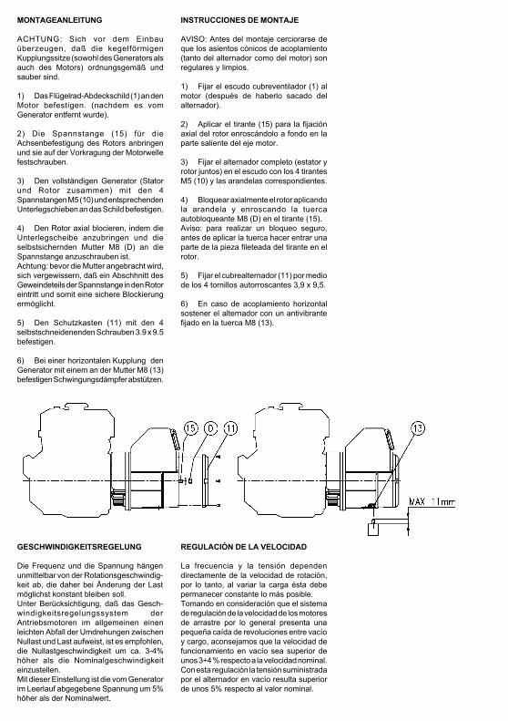
MONTAGEANLEITUNG
ACHTUNG: Sich vor dem Einbauüberzeugen, daß die kegelförmigenKupplungssitze (sowohl des Generators alsauch des Motors) ordnungsgemäß undsauber sind.
1) Das Flügelrad-Abdeckschild (1) an denMotor befestigen. (nachdem es vomGenerator entfernt wurde).
2) Die Spannstange (15) für dieAchsenbefestigung des Rotors anbringenund sie auf der Vorkragung der Motorwellefestschrauben.
3) Den vollständigen Generator (Statorund Rotor zusammen) mit den 4Spannstangen M5 (10) und entsprechendenUnterlegschieben an das Schild befestigen.
4) Den Rotor axial blocieren, indem dieUnterlegscheibe anzubringen und dieselbstsichernden Mutter M8 (D) an dieSpannstange anzuschrauben ist.Achtung: bevor die Mutter angebracht wird,sich vergewissern, daß ein Abschhnitt desGeweindeteils der Spannstange in den Rotoreintritt und somit eine sichere Blockierungermöglicht.
5) Den Schutzkasten (11) mit den 4selbstschneidenenden Schrauben 3.9 x 9.5befestigen.
6) Bei einer horizontalen Kupplung denGenerator mit einem an der Mutter M8 (13)befestigen Schwingungsdämpfer abstützen.
INSTRUCCIONES DE MONTAJE
AVISO: Antes del montaje cerciorarse deque los asientos cónicos de acoplamiento(tanto del alternador como del motor) sonregulares y limpios.
1) Fijar el escudo cubreventilador (1) almotor (después de haberlo sacado delalternador).
2) Aplicar el tirante (15) para la fijaciónaxial del rotor enroscándolo a fondo en laparte saliente del eje motor.
3) Fijar el alternador completo (estator yrotor juntos) en el escudo con los 4 tirantesM5 (10) y las arandelas correspondientes.
4) Bloquear axialmente el rotor aplicandola arandela y enroscando la tuercaautobloqueante M8 (D) en el tirante (15).Aviso: para realizar un bloqueo seguro,antes de aplicar la tuerca hacer entrar unaparte de la pieza fileteada del tirante en elrotor.
5) Fijar el cubrealternador (11) por mediode los 4 tornillos autorroscantes 3,9 x 9,5.
6) En caso de acoplamiento horizontalsostener el alternador con un antivibrantefijado en la tuerca M8 (13).
GESCHWINDIGKEITSREGELUNG
Die Frequenz und die Spannung hängenunmittelbar von der Rotationsgeschwindig-keit ab, die daher bei Änderung der Lastmöglichst konstant bleiben soll.Unter Berücksichtigung, daß das Gesch-windigkeitsregelungssystem derAntriebsmotoren im allgemeinen einenleichten Abfall der Umdrehungen zwischenNullast und Last aufweist, ist es empfohlen,die Nullastgeschwindigkeit um ca. 3-4%höher als die Nominalgeschwindigkeiteinzustellen.Mit dieser Einstellung ist die vom Generatorim Leerlauf abgegebene Spannung um 5%höher als der Nominalwert.
REGULACIÓN DE LA VELOCIDAD
La frecuencia y la tensión dependendirectamente de la velocidad de rotación,por lo tanto, al variar la carga ésta debepermanecer constante lo más posible.Tomando en consideración que el sistemade regulación de la velocidad de los motoresde arrastre por lo general presenta unapequeña caída de revoluciones entre vacíoy cargo, aconsejamos que la velocidad defuncionamiento en vacío sea superior deunos 3÷4 % respecto a la velocidad nominal.Con esta regulación la tensión suministradapor el alternador en vacío resulta superiorde unos 5% respecto al valor nominal.
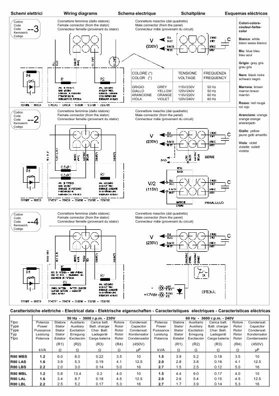
Colori-colors-couleur-farbe-color
Bianco: whiteblanc weiss blanco
Blu: blue bleublau azul
Grigio: grey grisgrau gris
Nero: black noireschwarz negro
Marrone: brownmarron braunmarròn
Rosso: red rougerot rojo
Arancione: orangeorange orangeanaranjado
Giallo: yellowjaune gelb amarillo
Viola: violetviolette violettvioleta
Schemi elettrici Wiring diagrams Schema electrique Schaltpläne Esquemas eléctricos
COLORE (*) TENSIONE FREQUENZACOLOR (*) VOLTAGE FREQUENCY
GRIGIO GREY 115V/230V 50 HzGIALLO YELLOW 120V/240V 50 HzARANCIONE ORANGE 110V/220V 60 HzVIOLA VIOLET 120V/240V 60 Hz
Connettore femmina (dallo statore)Female connector (from the stator)Connecteur femelle (provenant du stator)
Connettore femmina (dallo statore)Female connector (from the stator)Connecteur femelle (provenant du stator)
Connettore femmina (dallo statore)Female connector (from the stator)Connecteur femelle (provenant du stator)
Connettore maschio (dal quadretto)Male connector (from the panel)Connecteur mâle (provenant du circuit)
Connettore maschio (dal quadretto)Male connector (from the panel)Connecteur mâle (provenant du circuit)
Connettore maschio (dal quadretto)Male connector (from the panel)Connecteur mâle (provenant du circuit)
CodiceCodeCodeKennzeich.Codigo
--3
CodiceCodeCodeKennzeich.Codigo
--2
CodiceCodeCodeKennzeich.Codigo
--4
Tipo Potenza Statore Ausiliario Carica batt. Rotore Condensat. Potenza Statore Ausiliario Carica batt. Rotore Condensat.Type Power Stator Auxiliary Batt. charger Rotor Capacitor Power Stator Auxiliary Batt. charger Rotor CapacitorType Puissance Stator Excitation Char. Batt. Rotor Condensat. Puissance Stator Excitation Char. Batt. Rotor Condensat.Typ Leistung Stator Erregung Ladegerät Rotor Kondensator Leistung Stator Erregung Ladegerät Rotor KondensatorTipo Potencia Estator Excitaciòn Carga baterìa Rotor Condensador Potencia Estator Excitaciòn Carga baterìa Rotor Condensador
(R1) (R2) (R3) (R4) (450V) (R1) (R2) (R3) (R4) (450V)kVA Ω Ω Ω Ω µF kVA Ω Ω Ω Ω µF
R80 MBS 1.2 6.0 8.0 0.22 3.5 10 1.5 3.9 5.2 0.18 3.5 10R80 LAS 1.6 3.9 5.3 0.19 4.1 12.5 2.0 2.8 3.8 0.16 4.1 12.5R80 LBS 2.2 2.0 3.0 0.14 5.0 16 2.7 1.5 2.5 0.12 5.0 16
R80 MBL 1.2 5.8 13.4 0.2 4.0 10 1.5 4.4 9.0 0.17 4.0 10R80 LAL 1.6 3.4 8.7 0.18 4.5 12.5 2.0 2.6 5.4 0.15 4.5 12.5R80 LBL 2.2 2.5 5.2 0.17 5.3 16 2.7 1.7 3.9 0.14 5.3 16
50 Hz - 3000 r.p.m. - 230V 60 Hz - 3600 r.p.m. - 240V
Caratteristiche elettriche - Electrical data - Elektrische eigenschaften - Caracteristiques electriques - Caracteristicas elèctricas
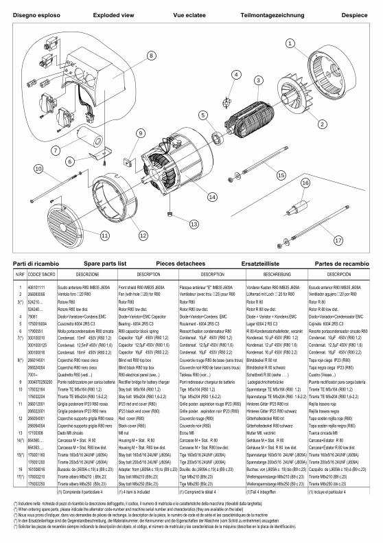
Disegno esploso Exploded view Vue eclatee Teilmontagezeichnung
Parti di ricambio Spare parts list Pieces detachees Ersatzteilliste
Despiece
Partes de recambio
11 12
9
13
14
106
7
8
43
1516
17
5
2
1
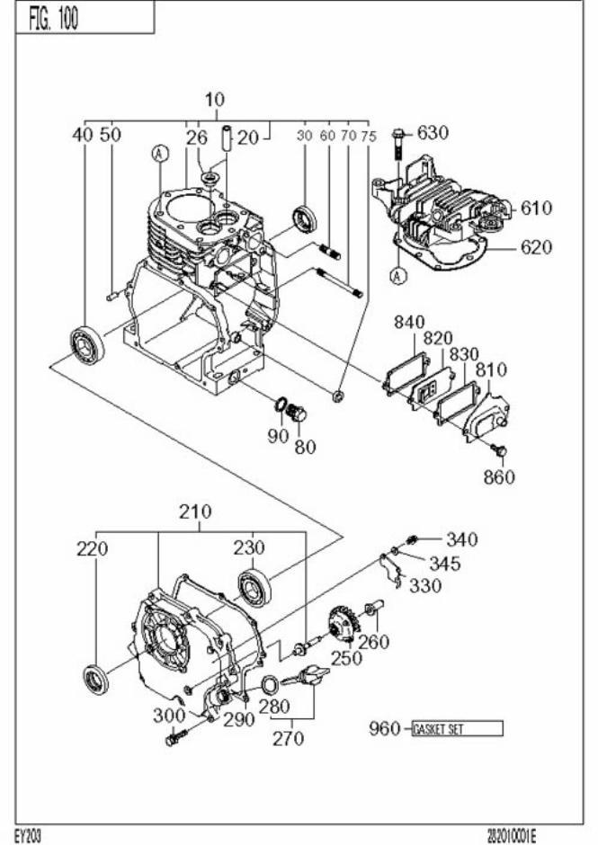
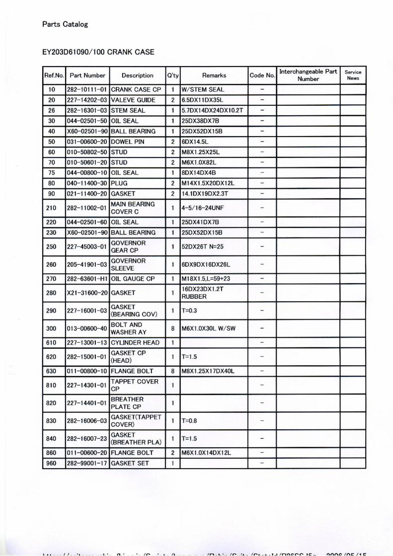
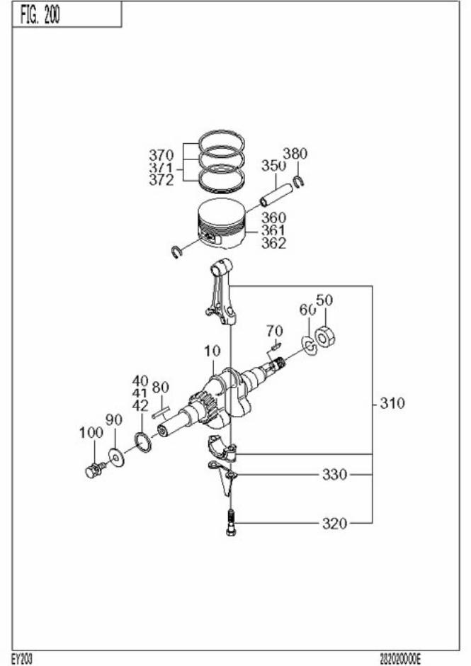
N.RIF CODICE SINCRO DESCRIZIONE DESCRIPTION DESCRIPTION BESCHREIBUNG DESCRIPCIÓN
1 406101111 Scudo anteriore R80 IMB35 J609A Front shield R80 IMB35 J609A Flasque antérieur "E" IMB35 J609A Vorderer Kasten R80 IMB35 J609A Escudo anterior R80 IMB35 J609A2 266083006 Ventola foro ∅ 20 R80 Fan (with hole ∅ 20) for R80 Ventilateur (avec trou ∅ 20) pour R80 Lüfterrad mit Loch ∅ 20 für R80 Ventilador agujero ∅ 20 por R80
3(*) 524210.... Rotore R80 Rotor R80 Rotor R80 Rotor R 80 Rotor R 80524240.... Rotore R80 low dist. Rotor R80 low dist. Rotor R80 low dist. Rotor R 80 low dist. Rotor R 80 low dist.
4 79061 Diodo+Varistore+Condens.EMC Diode+Varistor+EMC Capacitor Diode+Varistor+Condens. EMC Diode + Varistor + Kondens.EMC Diodo+Variador+Condensador EMC5 1750016004 Cuscinetto 6004 2RS C3 Bearing - 6004 2RS C3 Roulement - 6004 2RS C3 Lager 6004 2 RS C3 Cojinete 6004 2RS C36 17900551 Molla portacondensatore R80 zincata R80 capacitor block spring Ressort fixation condensateur R80 R 80-Kondensatorhaltefeder, verzinkt Resorte portacondensador cincato R80
7(*) 300100010 Condensat. 10mF 450V (R80 1,2) Capacitor 10µF 450V (R80 1,2) Condensat. 10µF 450V (R80 1,2) Kondensat. 10 µF 450V (R80 1.2) Condensat. 10µF 450V (R80 1,2)3001000125 Condensat. 12,5mF 450V (R80 1,6) Capacitor 12,5µF 450V (R80 1,6) Condensat. 12,5µF 450V (R80 1,6) Kondensat. 12 µF 450V (R80 1.6) Condensat. 12,5µF 450V (R80 1,6)300100016 Condensat. 16mF 450V (R80 2,2) Capacitor 16µF 450V (R80 2,2) Condensat. 16µF 450V (R80 2,2) Kondensat. 16 µF 450V (R80 2.2) Condensat. 16µF 450V (R80 2,2)
8(*) 266014001 Coperchio R80 rosso cieco Blind red R80 top box Couvercle rouge R80 de base (sans trous) Blinddeckel R 80 rot Tapa roja ciega IP23 (R80)266024004 Coperchio R80 nero cieco Blind black R80 top box Couvercle noir R80 de base (sans trous) Blinddeckel R 80 schwarz Tapa negra ciega IP23 (R80)7001-- Quadretto R80 (vedi...) R80 electrical panel (see...) Tableau R80 (voir...) Schaltbrett R 80 (siehe . . . ) Cuadro (Véase...)
9 3004070250200 Ponte raddrizzatore per carica batteria Rectifier bridge for battery charger Pont redresseur chargeur de batterie Ladegleichrichterbrücke Puente rectificador para carga batería10 176032164 Tirante TE M5x164 (R80 1,2) Stay bolt M5x164 (R80 1,2) Tige M5x164 (R80 1,2) Spannstange TE M5x164 (R80 1.2) Tirante TE M5x164 (R80 1,2)
176032204 Tirante TE M5x204 (R80 1,6-2,2) Stay bolt M5x204 (R80 1,6-2,2) Tige M5x204 (R80 1,6-2,2) Spannstange TE M5x204 (R80 1.6-2.2) Tirante TE M5x204 (R80 1,6-2,2)11 266012001 Griglia posteriore IP23 R80 rossa IP23 red end cover (R80) Grille poster. aspiration rouge IP23 (R80) Hinteres Gitter IP23 R80 rot Rejilla trasera roja
266022001 Griglia posteriore IP23 R80 nera IP23 black end cover (R80) Grille poster. aspiration noir IP23 (R80) Hinteres Gitter IP23 R80 schwarz Rejilla trasera negra12 266054001 Coperchio supporto griglia R80 rosso Red cover (R80) Couvercle rouge (R80) Gitterhaltedeckel R80 rot Tapa sostén rejilla roja (R80)
266064004 Coperchio supporto griglia R80 nero Black cover (R80) Couvercle noir (R80) Gitterhaltedeckel R80 schwarz Tapa sostén rejilla negra (R80)13 17100308 Dado M8 zincato M8 nut Ecrou M8 Mutter M8, verzinkt Tuerca cincada M8
14(*) 664360..... Carcassa M + Stat. R 80 Housing M + Stat. R 80 Carcasse M + Stat. R 80 Gehäuse M + Stat. R 80 Carcasa+Estator R 80 664363..... Carcassa M + Stat. R80 low dist. Housing M + Stat. R80 low dist. Carcasse M + Stat. R80 low dist. Gehäuse M + Stat. R 80 low dist. Carcasa+Estator R 80 low dist.
15(*) 176001160 Tirante 160x5/16 24UNF (J609A) Stay bolt 160x5/16 24UNF (J609A) Tige 160x5/16 24UNF (J609A) Spannstange 160x5/16 24UNF (J609A) Tirante 160x5/16 24UNF (J609A)176001200 Tirante 200x5/16 24UNF (J609A) Stay bolt 200x5/16 24UNF (J609A) Tige 200x5/16 24UNF (J609A) Spannstange 200x5/16 24UNF (J609A) Tirante 200x5/16 24UNF (J609A)
16 161008016 Bussola: da (J609A c.19) a (B9 c.23) Adapter: from (J609A c.19) to (B9 c.23) Douille: de (J609A c.19) à (B9 c.23) Buchse: von (J609A c. 19) bis (B9 c.23) Cazquillo: de (J609A c.19) à (B9 c.23)17(*) 176002210 Tirante albero M8x210 ( B9c.23) Stay bolt M8x210 (B9c.23) Tige M8x210 (B9c.23) Wellenspannstange M8x210 (B9 c.23) Tirante M8x210 (B9 c.23)
176002250 Tirante albero M8x250 (B9c.23) Stay bolt M8x250 (B9c.23) Tige M8x250 (B9c.23) Wellenspannstange M8x250 (B9 c.23) Tirante M8x250 (B9 c.23)(1) Comprende il particolare 4 (1) 4 item is included (1) Comprend le détail 4 (1)Teil 4 inbegriffen (1) Incluye el particular 4
(*) Includere nella richiesta di pezzi di ricambio la descrizione dell'oggetto, il codice, il numero di matricola e le caratteristiche della macchina (rilevabili dalla targhetta).(*) When ordering spare parts, please indicate the alternator code-number and machine serial number and characteristics (they are available on the label) (*) Nous vous prons d’indiquer, dans vos demandes de pièces de rechange, la description de la pièce, le numéro de code et de série et les caractéristiques de la machine(*) In den Ersatzteilanfrage sind die Gegenstandbeschreibung, die Materialnummer, die Kennummer und die Eigenschaften der Maschine (vom Schild zu entnehmen) anzugeben.(*) Solicitar las piezas de recambio siempre indicando la descripción del objeto, el código, el número de matrícula y las características de la máquina (descritas en la placa de identificación).
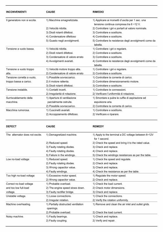
INCONVENIENTI CAUSE RIMEDIO
Il generatore non si eccita. 1) Macchina smagnetizzata. 1) Applicare ai morsetti d’uscita per 1 sec. una tensione continua compresa tra 6 ÷12 V.
2) Velocità ridotta. 2) Controllare i giri e portarli al valore nominale.3) Diodi rotanti difettosi. 3) Controllare e sostituire.4) Condensatore difettoso 4) Controllare e sostituire.5) Guasto negli avvolgimenti. 5) Controllare le resistenze degli avvolgimenti come da
tabella.Tensione a vuoto bassa. 1) Velocità ridotta. 1) Controllare i giri e regolare.
2) Diodi rotanti difettosi. 2) Controllare e sostituire.3) Condensatore di valore errato 3) Controllare e sostituire.4) Avvolgimenti avariati. 4) Controllare le resistenze degli avvolgimenti come da
tabella.Tensione a vuoto troppo 1) Velocità motore troppo alta. 1) Controllare i giri e regolare.alta. 2) Condensatore di valore errato 2) Controllare e sostituire.Tensione corretta a vuoto, 1) Possibile sovraccarico. 1) Controllare la corrente di carico.troppo bassa a carico. 2) Il motore rallenta. 2) Controllare dimensionamento motore.
3) Diodi rotanti difettosi. 3) Controllare e sostituire.Tensione instabile. 1) Contatti incerti. 1) Controllare le connessioni. 2) Irregolarità di rotazione. 2) Verificare l’uniformità di rotazione.Surriscaldamento della 1) Aperture di ventilazione 1) Smontare e pulire le cuffie di aspirazione edmacchina. parzialmente ostruite. espulsione aria. 2) Possibile sovraccarico. 2) Controllare la corrente di carico.Macchina rumorosa. 1) Cuscinetti avariati. 1) Controllare e sostituire. 2) Accoppiamento difettoso. 2) Verificare e riparare.
DEFECT CAUSE REMEDY
The alternator does not excite. 1) Demagnetized machine. 1) Apply to the terminal a DC voltage between 6÷12V for 1 second.
2) Reduced speed. 2) Check the speed and bring it to the rated value.3) Faulty rotating diodes. 3) Check and replace.4) Faulty rotating diodes. 4) Check and replace.5) Failure in the windings. 5) Check the windings resistances as per the table.
Low no-load voltage 1) Reduced speed. 1) Check the speed and regulate.2) Faulty rotating diodes. 2) Check and replace.3) Wrong capacitor value. 3) Check and replace.4) Faulty windings. 4) Check the resistance as per the table.
Too high no-load voltage 1) Excessive motor speed. 1) Regulate the motor speed.2) Wrong capacitor value. 2) Check and replace.
Correct no-load voltage 1) Probable overload. 1) Check the load current.and too low full-load 2) The engine speed slows down. 2) Check motor dimensions.voltage. 3) Faulty rectifier bridge. 3) Check and replace.Unstable voltage. 1) Loose connections. 1) Check the connections.
2) Irregular rotation. 2) Verify the rotation uniformity.Machine overheating. 1) Partially obstructed ventilation 1) Remove and clean the air inlet and outlet grids.
openings.2) Probable overload. 2) Check the load current.
Noisy machine. 1) Faulty bearings. 1) Check and replace.2) Faulty coupling. 2) Verify and repair.
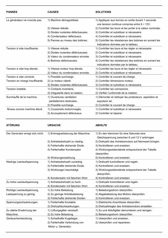
PANNES CAUSES SOLUTIONS
Le générateur ne s’excite pas. 1) Machine démagnétisée. 1) Appliquer aux bornes en sortie durant 1 seconde une tension continue comprise entre 6 ÷ 12V.
2) Vitesse réduite. 2) Contrôler les tours et les porter à la valeur nominale.3) Diodes roulantes défectueuses. 3) Contrôler et substituer si nécessaire.4) Condensateur défectueux. 4) Contrôler et substituer si nécessaire.5) Pannes au niveau des bobines. 5) Contrôler les résistances des bobines en suivant les
indications données par le tableau. Tension à vide insuffisante. 1) Vitesse réduite. 1) Contrôler les tours et les régler si nécessaire.
2) Diodes roulantes défectueuses. 2) Contrôler et substituer si nécessaire.3) Valeur du condensateur erronée. 3) Contrôler et substituer si nécessaire.4) Bobines défectueuses. 4) Contrôler les résistances des bobines en suivant les
indications données par le tableau. Tension à vide trop élevée. 1) Vitesse moteur trop élevée. 1) Contrôler les tours et les régler si nécessaire.
2) Valeur du condensateur erronée. 2) Contrôler et substituer si nécessaire.Tension à vide correcte. 1) Possible surcharge. 1) Contrôler le courant de charge.Tension en charge insuffisante. 2) Le moteur ralenti. 2) Contrôler dimensions moteur.
3) Diodes roulantes défectueuses. 3) Contrôler et substituer si nécessaire.Tension instable. 1) Contacts incertains. 1) Contrôler les connexions.
2) Irrégularité dans la rotation. 2) Vérifier l’uniformité de la rotation.Surchauffe de la machine. 1) Ouvertures ventilation 1) Démonter et nettoyer les protecteurs aspiration et
partiellement obstruées. expulsion air.2) Possible surcharge. 2) Contrôler le courant de charge.
Niveau sonore machine élevé. 1) Coussinets endommagés. 1) Contrôler et substituer si nécessaire.2) Accouplement défectueux. 2) Contrôler et réparer.
STÖRUNG URSACHE ABHILFE
Der Generator erregt sich nicht. 1) Entmagnetisierung der Maschine. 1) En den klemmen für eine Sekunde eine Gleichspannung zwischen 6 und 12 V anbringen
2) Antriebsdrehzahl zu niedrig. 2) Drehzahl des Antriebsmotors auf Nennwert bringen.3) Fehlerhafte drehende Diode. 3) Kontrollieren und ersetzen.4) Fehlerhafter Kondensator 4) Wicklungswiderstände entsprechend der Tabelle
überprüfen.5) Wicklungensstörung. 5) Kontrollieren und ersetzen.
Niedrige Leerlaufspannung. 1) Antriebsdrehzahl zuniedrig. 1) Drehzahl kontrollieren und regeln.2) Fehlerhafte drehende Diode. 2) Kontrollieren und ersetzen.3) Wicklungen beschädigt. 3) Wicklungswiderstände entsprechend der Tabelle
überprüfen.4) Kondensator mit falschen Wert 4) Kontrollieren und ersetzen
Zu hohe Leerlaufspannung. 1) Antriebsdrehzahl zu hoch. 1) Drehzahl kontrollieren und regeln.4) Kondensator mit falschen Wert 4) Kontrollieren und ersetzen
Richtige Leerlaufspannung, 1) Zu hohe Belastung. 1) Belastungsstrom überprüfen.Lastspannung zu gering. 2) Zu geringe Antriebsleistung. 2) Abgabeleistung des Motors überprüfen.
3) Fehlerhafte drehende Dioden 3) Kontrollieren und ersetzen.Spannungsschwankungen. 1) Fehlerhafte Kontakte. 1) Elektrische Anschlüsse überprüfen.
2) Drehzahlschwankungen. 2) Drehzahlregler des Antriebsmotors einstellen.Zu stärke Erwärmung der 1) Lüftungsgitter verstopft. 1) Zu-und Abluftgitter demontieren und reinigen.Maschine. 2) Zu hohe Belastung. 2) Belastungsstrom überprüfen.Geräuschentwicklung. 1) Schadhafte Kugellager. 1) Uberprüfen und ersetzen.
2) Fehlerhafte Verbindung von 2) Uberprüfen und reparieren. Motor u. Generator.
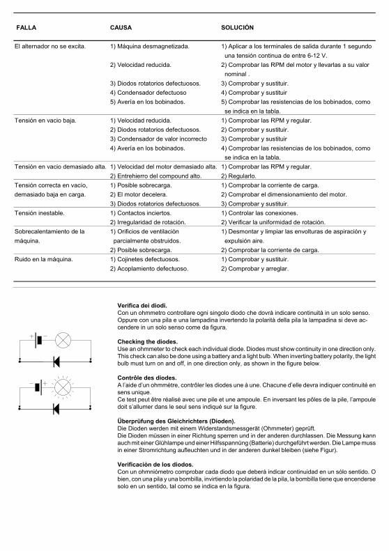
Verifica dei diodi.Con un ohmmetro controllare ogni singolo diodo che dovrà indicare continuità in un solo senso.Oppure con una pila e una lampadina invertendo la polarità della pila la lampadina si deve ac-cendere in un solo senso come da figura.
Checking the diodes.Use an ohmmeter to check each individual diode. Diodes must show continuity in one direction only.This check can also be done using a battery and a light bulb. When inverting battery polarity, the lightbulb must turn on and off, in one direction only, as shown in the figure below.
Contrôle des diodes.A l’aide d’un ohmmètre, contrôler les diodes une à une. Chacune d’elle devra indiquer continuité ensens unique.Ce test peut être réalisé avec une pile et une ampoule. En inversant les pôles de la pile, l’ampouledoit s’allumer dans le seul sens indiqué sur la figure.
Überprüfung des Gleichrichters (Dioden).Die Dioden werden mit einem Widerstandsmessgerät (Ohmmeter) geprüft.Die Dioden müssen in einer Richtung sperren und in der anderen durchlassen. Die Messung kannauch mit einer Glühlampe und einer Hilfsspannüng (Batterie) durchgeführt werden. Die Lampe mussin einer Stromrichtung aufleuchten und in der anderen dunkel bleiben (siehe Figur).
Verificaciòn de los diodos.Con un ohmniómetro comprobar cada diodo que deberá indicar continuidad en un sólo sentido. Obien, con una pila y una bombilla, invirtiendo la polaridad de la pila, la bombilla tiene que encendersesolo en un sentido, tal como se indica en la figura.
FALLA CAUSA SOLUCIÓN
El alternador no se excita. 1) Máquina desmagnetizada. 1) Aplicar a los terminales de salida durante 1 segundo una tensión continua de entre 6-12 V.
2) Velocidad reducida. 2) Comprobar las RPM del motor y llevarlas a su valor nominal .
3) Diodos rotatorios defectuosos. 3) Comprobar y sustituir.4) Condensador defectuoso 4) Comprobar y sustituir5) Avería en los bobinados. 5) Comprobar las resistencias de los bobinados, como
se indica en la tabla.Tensión en vacio baja. 1) Velocidad reducida. 1) Comprobar las RPM y regular.
2) Diodos rotatorios defectuosos. 2) Comprobar y sustituir.3) Condensador de valor incorrecto 3) Comprobar y sustituir4) Avería en los bobinados. 4) Comprobar las resistencias de los bobinados, como
se indica en la tabla.Tensión en vacio demasiado alta. 1) Velocidad del motor demasiado alta. 1) Comprobar las RPM y regular.
2) Entrehierro del compound alto. 2) Regularlo.Tensión correcta en vacío, 1) Posible sobrecarga. 1) Comprobar la corriente de carga.demasiado baja en carga. 2) El motor decelera. 2) Comprobar el dimensionamiento del motor.
3) Diodos rotatorios defectuosos. 3) Comprobar y sustituir.Tensión inestable. 1) Contactos inciertos. 1) Controlar las conexiones.
2) Irregularidad de rotación. 2) Verificar la uniformidad de rotación.Sobrecalentamiento de la 1) Orificios de ventilación 1) Desmontar y limpiar las envolturas de aspiración y máquina. parcialmente obstruidos. expulsión aire.
2) Posible sobrecarga. 2) Comprobar la corriente de carga.Ruido en la máquina. 1) Cojinetes defectuosos. 1) Comprobar y sustituir.
2) Acoplamiento defectuoso. 2) Comprobar y arreglar.
SINCRO s.r.l.Via Tezze,3 - Loc. Cereda - 36073 - Cornedo Vicentino - (Vi) ITALY
Cereda di Cornedo, li 02/01/97
DICHIARAZIONE DI CONFORMITA'
La società
dichiara sotto la propria responsabilità chegli alternatori
serie R80
sono costruiti e collaudati in accordo allenorme di seguito indicate:
e risultano conformi:
1) ai requisiti generali di sicurezza stabilitidalla Direttiva Bassa Tensione del 19 Feb-braio 1973 (73/23 CEE), recepita in Italiacon la legge n°791 del 18 Ottobre 1977.
2) alla Direttiva 89/336 CEE (mod. dalla93/68 CEE) riguardante il ravvicinamentodelle legislazioni degli stati membri in ma-teria di compatibilità elettromagnetica.La verifica di compatibilità è stata condottain base alle seguenti norme:
Gli alternatori oggetto della presente dichia-razione sono da intendersi come compo-nenti; pertanto vige il divieto di messa inservizio prima che le macchine in cui sa-ranno incorporati siano dichiarate conformialle direttive riguardanti la sicurezza (CEE89/392, art.4, allegato 2, lettera B; CEE 91/368, art.1) e la compatibilità elettromagne-tica.
CEI EN 60034-1 (CEI 2-3 - NF 51.100 - VDE 0530 - BS 4999-5000)CEI EN 60204-1 (CEI 44-5)EN 292-1, 292-2IEC 34.1, 34.5
EN 55011 (CEI 110-6)EN 50081-1 (CEI 110-7)EN 50082-1 (CEI 110-8)
CONFORMITY CERTIFICATE
The company
declares under its own responsibility thatthe alternators:
serie R80
have been manufactured and tested in com-pliance with the following standards
and thereby conform to:
1) all General Safety Requirements as pro-vided by the EEC Low Voltage Directivedated 19 February 1973 (73/23 EEC).
2) all principal safety requirement specifiedby the Committee for Adapting MemberStates Legal Regulation on ElectromagneticCompatibility (89/336 EEC, 93/68 EEC).The following standards were used to evalu-ate the electromagnetic compatibility:
The alternators covered by this certificatemust be considered as components andtherefore prohibited from being placed inoperation before the machine in which theywill be used has been certificated for con-formity to safety directives (EEC 89/392,art.4, point 2, letter B; EEC 91/368,art.1) and for electromagnetic compatibil-ity.
SINCRO s.r.l.L' amministratore unico
Der AlleingeschäftsführerEl Gerente
SOGA LINO
KONFORMITÄTSERKLÄRUNG
Die Firma
erklärt unter der eigenen Verantwortung,daß der Bau und die Abnahme der Genera-toren
Baureihe R80
den nachstehenden Vorschriften entspricht:
darüberhinaus erfüllen sie:
1) die allgemeinen Sicherheitsan-forderungen der Richtlinie für Niederspan-nung vom 19 Februar 1973 (73/23 CEE), inItalien mit dem Gesetz Nr. 791 vom 18 Ok-tober 1977 aufgenommen.
2) die Richtlinie 89/336CEE (Mod. der 93/68 CEE) bezüglich der Annäherung derGesetzgebungen der Mitgliedsstaaten inSachen elektromagnetischer Kompatibilität.Die Kompatibilitätsprüfung wurde mit Zu-grundelegung folgender Normen ausge-führt:
Die Generatoren, Gegenstand dieser Erklä-rung, sind als Komponenten zu verstehen;daher ist ihre Inbetriebnahùe verboten, be-vor nicht die Maschinen, in die sie integriertwerden, mit den Richtlinien bezüglich Si-cherheit (CEE 89/392, Art. 4, Anlage 2,Buchstabe B; CEE 91/368, Art. 1) und elek-trischer Kompatibiolität für konform erklärtwerden.
DECLARATION DE CONFORMITE'
La société
déclare sous sa propre responsabilité queles alternateurs
série R80
sont construits et testés dans le respect desnormes indiquées ci-après:
et sont conformes:
1) Aux conditions générales de sécuritéétablies par la Directive relative à la bassetension du 19 Février 1973 (73/23 CEE),adoptée par l’Italie par promulgation de laloi n°791 du 18 Octobre 1977.
2) A la Directive 89/336 CEE (et modificationsuccessive 93/68 CEE) concernantl’harmonisation des législations des étatsmembres en matière de comptabilitéélectromagnétique.La vérification de compatibilité a étéeffectuée conformément aux normessuivantes:
Les alternateurs objets de la présentedéclaration doivent être considérés commeétant des composants. En conséquence, lamise en service de ces derniers est interdi-te, avant la mise en conformité des machinesauxquelles ils seront incorporés. Les ditesmachines devront être déclarées conformesaux directives regardant la sécurité (CEE89/392, art.4, annexe 2, lettre B; CEE 91/368, art.1) et la compatibilitéélectromagnétique.
DECLARACIÓN DE CONFORMIDAD
La sociedad
declara bajo la propia responsabilidad quelos alternadores
serie R80
han sido fabricados y probados siguiendola normativa que se detalla a continuación:
y cumplen:
1) las prescripciones que sobre seguridadquedan definidas en la Norma sobre la BajaTensión del 19 de Febrero del 1973 (73/23CEE) introducida en Italia con la ley n° 791del 18 de Octubre del 1977.
2) la Norma 89/336 CEE (y sucesiva modi-ficación 93/68 CEE) sobre la compatibili-dad elctromagnética.La prueba de compatibilidad se ha realiza-do en base a las siguientes normas:
Los alternadores objeto de la presente de-claración han de entenderse como compo-nentes; por lo tanto se prohibe su puesta enservicio antes de que las máquinas a lascuales se acoplarán no se declaren confor-mes a las normas sobre seguridad (CEE89/392, art. 4, anexo 2, letra B; CEE 91/368,art. 1) y sobre compatibilidadelctromagnética.
Cereda di Cornedo, li 02/01/97
EN 55011 (CEI 110-6)EN 50081-1 (CEI 110-7)EN 50082-1 (CEI 110-8)
Cod
090
0207
- 03
/00
La S
INC
RO
si r
iser
va d
i app
orta
re m
odifi
che
senz
a pr
eavv
iso.
The
man
ufac
ture
r res
erve
s th
e rig
ht to
mod
ify fe
atur
es w
ithou
t not
ice.
Les
vale
urs
peuv
ent s
ubir
des
varia
tions
san
s pr
éavi
s.D
ie W
erte
kön
nen
ohne
Vor
ankü
ndig
ung
Ände
rung
en u
nter
zoge
n w
erde
n.La
Sin
cro
se re
serv
a el
der
echo
de
apor
tar l
as m
odifi
caci
ones
sin
pre
avis
o.
SINCRO s.r.l. - Via Tezze, 3 - Loc. Cereda - 36073, Cornedo (Vi), Italy - Tel. 0445/450500 - Fax 0445/446222 - e-mail: [email protected]
SINCRO s.r.l.
Via Tezze,3 - Loc. Cereda - 36073 - Cornedo Vicentino - (Vi) ITALY
CEI EN 60034-1 (CEI 2-3 - NF 51.100 - VDE 0530 - BS 4999-5000)CEI EN 60204-1(CEI 44-5)EN 292-1, 292-2IEC 34.1, 34. 5
SINCRO s.r.l.L' amministratore unico
The chairman L’Administrateur unique
SOGA LINO